1
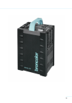
Operating instructions
mobil
www.broncolor.com
Operating instructions
broncolor
Mobil
Before use
Please read all the information contained in these operating instructions carefully. They contain
important details on the use, safety and maintenance of the appliance. Keep these operating
instructions in a safe place and pass them on to further users if necessary.
Observe the safety instructions.
page
Contents
Important safety instructions
2
Attention: Read before starting up the power pack
3
Controls and displays
4
1.
Startup
7
2.
Energy control
8
3.
Modelling light
8
4.
Release and remote control
10
5.
Flash ready signals visual / audible
10
6.
Selecting additional functions
11
7.
Protective facilities / Fault indication
11
8.
Maintenance of rechargeable batteries
12
9.
Lamp bases
13
10.
Technical data
15
1
Important safety instructions
When using your photographic equipment, basic safety precautions should always be followed,
including the following:
1.
Read and understand all instructions before using.
2.
Close supervision is necessary when any appliance is used by or near children. Do not
leave appliance unattended while in use.
3.
Care must be taken as burns can occur from touching hot parts.
4.
Do not operate appliance with a damaged cable or if the appliance has been dropped or
damaged - until it has been examined by a qualified serviceman.
5.
Position the cable so that it will not be tripped over, pulled, or contact hot surfaces.
6.
If an extension cable is necessary, a cable with a current rating at least equal to that of the
appliance should be used. Cables rated for less amperage than the appliance may
overheat. When using a cable reel, it has to be unrolled before operating to avoid
overheating of the cable.
7.
Always turn off the power pack before connecting or disconnecting any lamp bases.
8.
Always unplug appliance from electrical socket before cleaning and servicing and when
not in use. Never jerk cable to pull plug from socket. Grasp plug and pull to disconnect.
9.
Let appliance cool completely before putting away. Loop cable loosely around appliance
when storing.
10. When putting away or winding up cables, take care they do not get in contact with hot
parts of the appliance or lamp bases.
11. To reduce the risk of electric shock, do not immerse this appliance in water or other
liquids.
12. To reduce the risk of electric shock, do not disassemble this appliance, but take it to a
qualified serviceman when service or repair work is required. Incorrect reassembly can
cause electric shock when the appliance is used subsequently.
13. The use of an accessory attachment not recommended by the manufacturer may cause a
risk of fire, electric shock, or injury to persons.
14. Connect this appliance only to a broncolor rechargeable battery or to an earthed socket.
15. Prevent metal objects from touching the broncolor battery contact surfaces.
2
Attention:
Read before starting up the power pack
-
Remove protective foil from battery contacts before use the unit.
-
Prior to replacing fuses, light bulbs or flash tubes, discharge the power pack and
disconnect from power supply. Disconnect the lamp base from the power pack.
-
These units are designed for use in dry conditions. Protect them from water and
from excessive exposure to dust by using the bag for power pack Mobil art. no.
36.513.00.
-
The units are not suitable for use in an environment where there is a risk of
explosion.
-
The accessories mounted onto the lamp bases may heat up to high temperatures
under specific conditions. Handle with care!
-
With due allowance for heat radiation, lamp bases with more than 100 W modelling
light may be directed against inflammable surfaces only at a minimum distance of
1 m.
-
For safety reasons, never operate the lamps without the protecting glass
in place.
-
Flash light contains, similar to sunlight, a specific portion of UV light. The
undesirable side effects on skin and eyes are considerably reduced by using flash
tubes and protecting glasses with a UV coating. Without these or other protective
filters, use with extreme care when shooting.
-
Even when disconnected from the power supply, dangerous voltages may remain
inside the unit. For this reason units should be opened by trained personnel only.
Excluding exchanging of the rechargeable battery.
-
broncolor power packs and lamp bases meet an extremely high safety standard.
When connecting broncolor products to other manufacturers' products, integrated
safety measures may become ineffective. Due to different design features and
contact assignment of the lamp plugs of other makes, the user may even be at
risk. We offer no guarantee and accept no liability for damages which may be
caused by this type of usage.
3
Controls and displays
1.
Switch "on/off"
2.
Switch "eco" for slow charge
3.
Battery charger socket for rechargeable battery
4.
Sync socket
5.1
Outlet I
5.2
Outlet II
6.
Master power selector "up/down"
7.
Slave cell
8.
Digital master power display
9.
Slave cell on/off
10.
IR receiver cell
11.
IR receiver on/off
12.
- Modelling lamp on/off;
- Choice of the proportional level of modelling light when using with Studio Booster
13.
Test key, green ready lamp
14.
Display charge state of the battery
15.
Rechargeable plug-in battery
4
5
Operation with Studio Booster
16.
Plug-in Studio Booster
16.1
Connection socket
16.2
Ready display
16.3
Fuse
16.4
Mains (AC-line) switch
16.5
Warning signal
16.6
Contact plug
16.7
Connecting screw
6
1.
Startup
1.1
Battery operation
1.1.1
Startup
Remove protective cardboards from battery contacts before use.
Use the switch "on/off" (1) to power up the unit and check the display "charge state"
(14). If the stored energy of the battery is less than 10 % it must be charged by means
of the charger (charging time approx. 3 hours for approx. 80 % of charge) or change to
another battery. Before powering up the unit for the first time, it is recommended to
charge the battery.
1.1.2
Changing the battery
Switch-off the unit before changing the battery.
Please check the contact surfaces of the battery for soiling to guarantee a good contact.
Prior to inserting the battery ensure that the side with the contacts is directed to the
opening of the power pack compartment.
Now slide the battery into the power pack compartment and use a slight pressure to
fasten it. Make sure that the contact springs in the battery compartment are not dirty or
damaged. When changing the battery press the locking mechanism (at the bottom)
together using finger and thumb. The two big contact springs slide the battery out so far
that the user may grip it.
1.2
Operation with Studio Booster
When using the plug-in Studio Booster (16) the unit becomes a complete studio power
pack. With the Studio Booster the Mobil power pack operates on 120 V and 230 V
(resp. 100 V and 230 V for the Japanese version). After disconnecting from the mains
(AC-line) supply all the settings are stored for a short time except the modelling light
proportionality level. The modelling lamps in use must correspond to the respective
mains (AC-line) voltage. The Studio Booster is connected by tightening the two screws
on the bottom simultaneously instead of inserting the battery in the power pack.
Attention:
• Before inserting the Studio Booster into the unit or removing it the mains (AC-line)
switch (16.4) on the Studio Booster must be turned off.
• The Studio Booster must only be operated when the warning indicator on the upper
side is not lit, and the unit must only be powered-up when the adapter (Booster) is
correctly screwed in.
• Use only earthed mains (AC-line).
7
On the front side of the Studio Booster is an operating indicator LED (16.2). This lights
green when the mains (AC-line) switch is turned on. When the integrated thermal
protection becomes active after longer flash series, this lights red during the cooling
time.
1.2.1
Startup
Use the switch "on/off" (1) and the mains (AC-line) switch (16.3) to power-up unit.
During the charging process the digital master power (8) flashes, after which it becomes
continuous.
2.
Energy control
2.1
Mobil
Use the "up/down" keys (6) to control the flash energy within a range of 4 f-stops. A
value of 10 in the display indicates maximum energy, 6 minimum. Whole numbers are
full f-stop intervals, decimals indicate 1/10 f-stop steps. Brief pressure on the "up/down"
keys (6) runs the power up (or down) by a 1/10 f-stop interval, prolonged pressure by a
full f-stop. The display (8) then blinks until charging or discharging has stabilized the
new level.
3.
Modelling light
3.1
Battery operation
The "mod" key (12) switches the modelling lamps on or off for all connected lamp
bases. When switched on, the green LED lights up. With regard to the control of the
modelling light this power pack has an automatic switch-off during battery-powered
operation. If the "mod" key is pressed again within 1,5s after activating the modelling
light, the switch-on time will be extended, with each pressure of the key, by a further
20s. By pressing the "mod" key, once only, to activate the modelling light, the switch-on
time is 20s. If the key is pressed 4 times consecutively the maximum switch-on time of
80s is attained. An audible signal sounds with each pressure of the key. This function
ensures a prolonged battery service life.
Specially for mobile work with this battery-operated power pack broncolor offers the
small lamp Mobilite, with built-in reflector and modelling light 12 V / 50 W and own
accessories with small dimensions. The lamp has an automatic thermal protection to
prevent overheating and an additional switch for the modelling light. The switch on the
lamp base permits selective lighting control with the modelling light. If only one lamp is
connected, it can be equipped with a modelling lamp 12 V / 100 W.
8
The Mobil power pack can also be used with conventional broncolor studio lamps
(Picolite, Pulso and Unilite lamps). The modelling light cannot be used during battery
operation.
The proportional modelling light is not working during battery operation (Mobilite).
Damage to the modelling lamp or power pack is impossible due to plug coding and
electronic protection circuit.
3.2
Operation with Studio Booster
When operating the power pack with Studio Booster the 12 V modelling light as well as
the cooling fan of the small lamp Mobilite is not operating. The modelling light of the
broncolor studio lamp bases (Picolite, Pulso and Unilite lamp bases) functions normally.
When using the mains (AC-line) adapter you may operate the modelling light
proportionally (see chap. 3.2.1) and adapt it to various output ratings of broncolor power
packs and monoblocs. Furthermore, the automatic switch-off after 20 – 80 s ceases.
Damage to the modelling lamp or power pack is impossible due to plug coding and
electronic protection circuit.
3.2.1
Proportionality
The brightness of the modelling light can be set proportionally to the flash intensity. To
assure proportionality when operating units with different power output ratings, the units
have various proportionality levels. These are guaranteed if the identical prop level has
been set for all power packs. The higher the digit, the brighter the modelling light. When
using the Mobil with two lamps it must be turned down one level lower than the other
power packs.
The proportionality level of the modelling light can be selected by a long pressure on the
"mod" key when the modelling light is off (12). Repeated actuation of the "up/down" key
(6) toggles through the following operating modes:
P
This level can be selected if only D160s are being used (highest proportionality
level). Proportional modelling light rated 1200 J.
P1
Proportional modelling light with broncolor power packs rated 6400 J.
P2
Proportional modelling light with broncolor power packs rated 3200 J.
P3
Proportional modelling light with broncolor power packs rated 1600 J.
P4/5 If a Mobil power pack is operated at a relatively low output level, the halogen
modelling light will be relatively weak and yellowish. To counteract this problem,
the Mobil is equipped with two additional modelling light proportionality levels: P4
for 800 J and less, P5 for 400 J and less.
HI
The unit operates with full modelling light power independent of the selected
flash output.
When the "mod" LED is blinking, the HI level can also be selected by pressing
the "up" or "down" key (6) for a longer period of time.
9
After the setting has been performed, the standard display can be activated by briefly
pressing the "mod" key.
Pressing the "mod" key for 1 second when the modelling lamp is on will give direct
access to the HI mode. To return press "mod" again.
Please note:
When the master switch of the Studio Booster is turned off, the setting
will revert to P3 when re-starting.
4.
Release and remote control
4.1
Photo cell (cell) and Infrared receiver (ir)
The photo cell can be switched on or off by using the "cell" key (9), the infrared receiver
by using the "ir" key (11). If they are activated the green LED light(s) up.
4.2
Infrared flash release channel
Mobil power packs can be triggered with broncolor infrared transmitters. If the power
pack is triggered via infrared, the flash release follows with a time delay of 1/1000 s.
The power pack can be triggered as soon as 100 % of the charge are reached.
4.3
Sync socket (4)
Synchronous cables art. no. 34.111.00 or 34.112.00 may be plugged into the socket to
release flashes via cable.
4.4
"test" key (13)
Key (13) allows the Mobil to be manually released.
5.
Flash ready signals visual / audible
5.1
The visual ready signal is the green LED at the "test" key (13). It lights up only when
the unit is fully charged. After a flash this LED goes out and lights up again when the
unit is fully charged once more.
5.2
The audible signal (buzzer) sounds when the power capacitors are at 100 % charge. It
may be switched on or off. This is explained in chapter 6.3.
10
5.3
Audible alarm signal
When the flash discharge fails, an audible warning signal of approx. 3 s duration will
sound.
6.
Selecting additional functions
6.1
Switch "eco" (2)
By using the key "eco" (2) the power pack switches to slow charge. This results in an
increased number of flashes per charge and a longer battery service life (see chap. 9).
This key only functions when in battery operation.
6.2
Automatic switch-off
The power pack switches-off
automatically after a selectable delay
time. A delay time of 15 min. is factoryset.
6.3
Setting of the delay time (in min.):
- Press the "up/down" keys (6)
simultaneously once.
Afterwards, the minute values
are set with the same keys. 3 s
after setting the display returns
to the energy display.
Buzzer
The audible signal sounds when the
power capacitors are at 100 % charge.
The signal may be switched on or off.
- Press the key "eco" (2) for 3 s.
7.
Protective facilities / Fault indication
7.1.
Monitoring in the power pack
To protect against overheating after long series of flashes with battery operation, the
unit will switch automatically to slow charge. The green “eco” LED lights up. If
nevertheless, the temperature continues to rise (e. g. due to external influence), the unit
will block. The message "th" will appear on the LCD display (8) until the unit has cooled
down sufficiently and is again ready for operation. If overheating occurs during
operation with the Studio Booster the operating indicator LED (16.2) will change from
green to red until the unit has cooled down.
11
If the power pack is unable to charge properly the LCD display (8) will show the
message „A1“. This can happen when there is afterglow of a flash tube or when the
battery is defective. The alarm will disappear after the fault has been corrected, and
subsequently switching the unit off and on again.
In case the voltage of the battery should sink extensively, the message "A2" will appear
on the LCD display (8). The unit is blocked for further triggering until the battery is
charged.
Units delivered from December 99 have an emergency stop switch. This completely
separates the battery from the unit when the battery is in danger of becoming flat. In this
situation the unit does not react to key operation. The battery must then be charged and
re-inserted in the unit.
If the alarms “A1” or “A2” continue to appear on the LCD display (8) after changing the
flash tube or the battery respectively, it is a must to contact the service station.
The message “A3” on the LCD display (8) indicates a technical defect. The unit must be
brought to the service station for a check.
If there is no flash discharge after a flash release (e. g. if a flash tube is not connected
in the lamp), an audible alarm signal will sound.
7.2
Thermal protection Mobilite
When the lamp base temperature rises during operation, the cooling fan will switch on
when necessary. If high temperatures build up due to longer, faster flash series (e. g.
operation with power pack Grafit) the flash triggering will be blocked.
8.
Maintenance of rechargeable batteries
8.1
Battery care
The battery used is sealed and does not require any special care. It does not show any
particular "memory effect" and does not need to be discharged regularly. Therefore it is
recommendable to leave the battery connected to the charger when not in use. Ensure,
however, that the battery does not discharge too far down as the unit will switch off
automatically when the battery voltage sinks too low. As a leakage current flows even
when the unit is switched off, it is highly recommendable to charge the battery after
use, and to leave it connected to the charger when not in use. If this is not possible, you
need to charge the battery all three months completely.
12
8.2
Battery charger
The battery can be charged in or out of the unit as the power pack as well as the battery
compartment are fitted with the necessary round plug. The charger no. 36.121.00
charges the battery in two levels, which are displayed by the integrated LED:
LED is lit continuously: The battery is charged in quick charge mode up to approx.
80 % of full charge. Duration depending on state of charge up
to 3 hours.
LED is flashing:
The battery is being recharged slowly to 100% (duration up to
approx. 5 hours) and then kept on charge.
LED is flashing green: The battery is kept on charge
If a defective battery is connected or one with very low voltage then the LED does not
blink anymore. In this case the battery must be replaced.
8.3
Charging battery on cigarette lighter
The connecting cable no. 34.113.00 is designed to charge the battery by means of a
cigarette lighter of a car or goods vehicle with 12V battery. The charging time remains
about the same as mentioned above.
9.
Lamp bases
9.1
General
The flash energy is distributed symmetrically to the lamps connected.
The Mobil power pack can basically be operated with all lamps of the broncolor range
upto 3200 J. Specially for mobile work with this battery-operated power pack broncolor
offers the small lamp Mobilite art. no. 32.010.00 with built-in reflector and halogen light
12 V / 50 W, and own accessories with small dimensions identical to the Picolite
accessories. The Pulso adapter art. no. 33.501.00 allows the use of light reflectors and
accessories from the Pulso range. If the Mobil power pack is being operated with
battery, the modelling light of the traditional broncolor studio lamp bases cannot be
used.
More details about the small lamps Mobilite and Picolite may be found in the
corresponding product information.
9.2
Replacing flash tubes and halogen lamps
Prior to any change of the flash tube, the lamp base must be disconnected from the
power pack! Halogen lamps and flash tubes can be plugged in.
13
To change the flash tube and halogen lamp release the spring ring and remove the
protecting glass. The flash tube must be pulled out straight along the lamp base axis.
When inserting the tube be sure that it is fully pushed in.
Taking the lifespan into consideration, the halogen lamp should not be handled with
bare hands. Finally, replace the protecting glass and fasten with the spring-ring. The
protecting glass is available in the versions "UVE" art. no. 34.332.55 (5500 K) and "UVE
matt" art. no. 34.335.55 (5500 K).
9.3
Lamp base plugs
The lamp base plugs and sockets carry mechanical interlocks to prevent inadvertent
disconnection. To unplug, push down the locking spring below the cable guide and lift
out the plug.
9.4
Extension cable to Mobilite
The extension cable (3,5m), available as accessory with the article no. 34.150.00, is
especially thin and flexible. It can only be used with the Mobilite. Should this cable be
used with other lamps the modelling light and fan will not function.
9.5
Fuses
Only sand-filled fuses of the type indicated on the type plate may be used; otherwise the
halogen lamp may explode.
14
10. Technical data
Flash energy
F-stop at distance of 2 m (6 1/2 ft),
100 ISO, reflector P70
Flash duration t 0.1 (t 0.5)
Charging time
(for 100 % of selected energy)
Can be switched to slow charge
mode
Ready display
Lamp base outlets
Power output distribution
Controls
Control range
Modelling light (Halogen)
Modelling light control
Flash release
No. of flashes per fully charged
battery
No. of sync sockets
Stabilized flash voltage
Standards
Power requirements
Dimensions
Weight kg
Battery operation
Operation with Studio Booster
1200 J
45 6/10
1500 J (Japan: 1200 J)
45 9/10 (Japan: 45 6/10)
for 1 lamp: 1/230 (1/680) s
for 2 lamps: 1/360 (1/1100) s
quick charge: 1.5 - 6 s
for 1 lamp: 1/220 (1/650) s
for 2 lamps: 1/330 (1/1000) s
230 V / 50 Hz: 0.6 - 2.4 s
120 V / 60 Hz: 0.6 - 2.4 s
100 V / 50 Hz: 0.7 - 2.9 s
no slow charge
slow charge to prolong
battery life: 2 - 13 s
visual and audible (can be switched off); signals when 100 % of selected
energy is reached
2
2
symmetrical
symmetrical
fully illuminated silicone keyboard as well as LED and LCD display, resistant
to dust and scratches.
over 4 f-stops in 1/10 f-stop intervals (1:16)
2 x 50 W or 1 x 100 W
200-240 V: 2 x 650 W
100-120 V: 2 x 300 W
automatic switch-off after 20 - 80 s full, proportional to flash energy, 5 prop
to prolong battery life
levels, adjustable to other broncolor
power packs and monoblocs and their
various output ranges
manual release button, photocell (can be switched off), infrared receiver (can
be switched off), sync cable, FCM 2, FCC, IRX 2
quick charge:
approx. 100 at full output
slow charge:
approx. 140 at fulll output
1
1
±1%
±1%
EC standard 73/23, UL 122
220-240 V / 50 Hz: 10 A
110-120 V / 60 Hz: 16 A
100 V / 50 Hz:
16 A
235 x 144 x 275 mm
235 x 144 x 332 mm
7 kg
Subject to change in the interest of product enhancement.
15