1
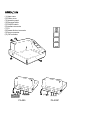
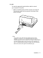
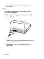
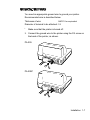
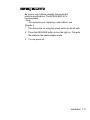
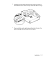
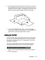
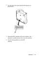
PA-295
Installation & Operating Instructions
99795 09/18/01
(1) Upper case
(2) Printer cover
(3) Operation panel
(4) Document table
(5) POWER switch
(6) Interface connector
(7) FG
(8) Drawer kick-out connector
(9) Power connector
(I 0) DIP switches
(I 0)
PA-295
(7) (8) (9)
PA-295P
The illustration below shows the items included for the standard
specification printer.
If any item is damaged, please contact your dealer for
assistance.
O.-
• Note:
See the Note on page 1-3 for information about the
screws.
Installation 1-1
The printer is protected during shipping by a transportation
damper that must be removed before you turn on the printer.
1. Pull the damper out and remove the strip of tape from the top
of the printer, as shown below.
Note:
steps: turn on the printer, press the RELEASE button, press the
FORWARD button, turn off the printer, and put the transportation
damper back where it was when you received the printer.
You need an appropriate interface cable to connect your
computer to the printer.
1-2 Installation
PA-295
You need an appropriate serial interface cable to connect
your computer to the printer.
1. Make sure that the printer and the computer are turned off.
Then plug the cable into the connector on the back of the
printer, as shown.
• Note:
Your printer comes with inch-type hexagonal lock screws
installed. If you plan to use an interface cable that requires
millimeter-type lock screws, replace the inch-type screws with the
enclosed millimeter-type screws by using a hex screwdriver (5
mm). To distinguish the two types of screws, see the illustration
below; the screw on the right is the millimeter type.
Installation 1-3
2. Connect the other end of the cable to the connector on
your computer.
PA-295
You need an appropriate parallel interface cable to connect
your computer to the printer.
1. Make sure that the printer and the computer are turned off.
Then plug the cable into the connector on the back of the
printer, as shown.
• Note:
Squeeze the wire clips on the printer together until they lock in
place on both sides of the connector.
2. Connect the other end of the cable to the connector on
your computer.
1-4 Installation
Plug the drawer cable into the drawer kick-out connector on the
back of the printer next to the computer interface connector.
PA-295
PA-295P
Do not connect a telephone line to the drawer kick out
connector.
Installation 1-5
You need an appropriate ground wire to ground your printer.
Recommended wire is described below.
Thickness of wire:
AWG 18 or equivalent
Diameter of terminal to be attached: 3.2
I
Make sure that the printer is turned off.
2. Connect the ground wire to the printer using the FG screw on
the back of the printer, as shown.
PA-295
PA-295P
Installation 1-7
This printer requires an external power supply. The EPSON
Power Supply PS-150 is recommended.
Using an incorrect power supply can cause serious damage to
the printer.
1. Make sure that the power supply is turned off.
2. Plug the power supply's cable into the printer's connector as
shown below. Note that the flat side of the connector faces
up.
PA-295
PA-295P
3. Plug the power cord into an outlet.
1-8 Installation
Be sure to use a ribbon cassette that meets the
printer's specifications. The EPSON ERC-27 is
recommended.
• Note:
For instructions on replacing a used ribbon, see
Chapter 2.
1. Turn the printer on using the power switch on its left side.
2. Press the RELEASE button to turn the light on. This puts
the printer in the paper release mode.
3. Turn the printer off.
Installation 1-9
Be sure to perform the steps above because it is necessary to
make sure that the printer is in the paper release mode before
you install the ribbon cassette.
4. Open the printer cover by slightly pressing the ridges on the
top left and pulling the cover forward, as shown in the
illustration below.
5. Check to see that the ribbon in the cassette is not creased or
twisted, Then turn the feed knob in the direction of the arrow
on the ribbon cassette to take up any slack in the ribbon.
1-10 Installation
6. Carefully insert the ribbon cassette in the printer as shown in
the illustration below. Notice exactly where the ribbon must go.
7. Then push firmly on the right side and then the left side of the
ribbon cartridge until each side clicks into place.
Installation 1-11
4. Insert the paper from either the front or the side, as shown in
the illustration below. Insert the paper into the printer until it is
stopped by the form stopper. The markings on the side of the
printer can also be used to judge how far to insert paper.
5. Check the PAPER OUT light. When you insert the paper
correctly, the PAPER OUT light goes out. If the PAPER OUT
light is still on, remove the paper and re-insert it.
Any time that you want to check the performance of your printer
you can run the self-test described below. This shows whether
your printer is working correctly. It is independent of any other
equipment or software.
The self test checks the control circuits, printer mechanisms,
print quality, RAM, ROM version', and DIP switch settings.
To Perform the self test, follow the steps below:
1. Insert a sheet of paper following the instructions on page 112.
2. Turn off the printer.
Installation 1-13
3. While holding down the RELEASE button, turn the printer
back on.
4. Remove your finger from the RELEASE button. The
printer prints the current printer settings and then eject
the paper.
5. Press the RELEASE button to eject the paper completely
and insert new paper to begin the second part of the test.
After the printer prints a pattern, it prints the following message:
***completed***
The printer ejects the paper; then enters the normal
mode.
You can change several interface settings by changing the DIP
switch settings. If you need to change any of these settings,
follow the steps below:
1. Make sure that the printer is off.
1-14 Installation
2. Turn the printer over and locate the DIP switches, as
shown below.
7
3. Notice that ON is marked on the set of switches. Use
tweezers or another narrow tool to move the switches.
4. Use the following tables to set the DIP
switches.
Installation 1-15
PA-295
Function
ON
OFF
Data reception error
Ignored
Prints'?'
2
Receive buffer capacity
35 bytes
512 bytes
3
Handshaking
XON/XOFF
DTR/DSR
4
Word length
7 bits
8 bits
5
Parity check
Yes
No
6
Parity selection
Switch
Even
Odd
7
8
See Transmission Speeds table below,
9
Pin 6 reset signal
Used
Not used
10
Pin 25 reset signal
Used
Not used
Transmission Speeds
Speed in Bits per Second
SW 7
SW 8
1200
ON
ON
2400
OFF
ON
4800
ON
OFF
9600
OFF
OFF
1-16 Installation
The control panel has three buttons and three
lights.
Buttons
All three of these buttons can be disabled or enabled by the ES C
c 5 command.
RELEASE
Pressing this button moves the rollers so that paper can be
inserted or removed.
REVERSE
Feeds the paper backward based on the line feed amount set
by ESC 2 and ESC 3.
FORWARD
Feeds the paper forward based on the line feed amount set
by ESC 2 and ESC 3.
You can also use the RELEASE button to start a selftest. See Chapter 1 for details.
POWER
This light is on whenever power is supplied to the printer.
Using the Printer 2-1
RELEASE
This light is on when the printer is in the paper release mode and
it is off when the printer is in the clamp mode. Paper can be
inserted only when the printer is in the paper release mode.
This light blinks to indicate an error condition in the following
cases:
• Paper jam
• Home position error
• Timing error
• Drive circuit error
• Power supply voltage error
If this light blinks, turn off the printer, make sure that no paper is
jammed in it, and then turn it back on. If the light is still blinking,
contact a qualified service person.
PAPER OUT
This light is on when paper is not inserted or is not inserted
correctly.
When your printing is not dark enough, it is time to replace the
ribbon.
First follow steps 1 through 4 in the "Installing the Ribbon" in
Chapter 1.
2-2 Using the Printer
Then remove the used ribbon by grasping the handle and pulling
straight out, as shown by the arrow in the illustration below.
Then follow the rest of the steps in "Insatlling the Ribbon" in Chapter 1.
Using the Printer 2-3
This chapter gives the solutions to some printer
problems.
Power Problems
The POWER light does not come
on.
Make sure that the power supply cables are correctly plugged
into the printer, the power unit, and to the power outlet.
Make sure that power is supplied to the power outlet. If the outlet
is controlled by a switch or timer, use another outlet.
The PAPER OUT light is on and nothing is printed.
If the PAPER OUT light is on, the paper is not inserted or is
not inserted correctly.
The RELEASE light is flashing and nothing is printed.
This indicates an error condition. Turn off the printer, make sure
that no paper is jammed in it, and then turn it back on. If the
RELEASE light is still flashing, contact a qualified service
person.
Troubleshooting 3-1
Printing Method:
Impact dot matrix
Head Wires
7-pin shuttle type
Printing Direction:
Unidirectional
Lines per second
5 x 7 font: 1.9 to 2.3
7 x 7 font: 1.9 to 2.3
Characters per line
5 x 7 font: 35
7 x 7 font: 42
Characters per inch:
5 x 7 font: ANK: 0.63
Graphics: 0.315
7 x 7 font: ANK: 0.63
Graphics: 0.315
Paper feed speed:
Approximately 12.5 lines (52.5 mm
12.10")/second)
(When the ESC d and FF commands are
used.)
Number of
characters
Alphanumeric characters: 95
Extended graphics: 128 x 3
International characters: 32
Character structure:
5 x 7 with 1-dot spacing (normal dot)
7 x 7 with 3-dot spacing (half dot)
Reference Information 4-1
Character size:
5 x 7 font:
ANK: 1.6 mm (.063") x 2.9 mm (.114")
Graphics: 1.9 mm (.075") x 2.9 mm
(.114")
7 x 7 font:
ANK: 1.3 mm (.051") x 2.9 mm (.114")
Graphics: 1.6 mm (.063") x 2.9 mm (.114")
4-2 Reference Information
Papertype:
Total thickness:
Normal (high quality), pressure
sensitive, and carbon copy
papers
Single Ply Paper: 0.09 to 25mm
(.0035" to .0098")
Copy Paper: 0.09 to 0.35mm
(.0035" to .0138")
Paper size:
Copy capability and
paper thickness:
80 mm (W) x 69 mm (L) to 182 mm
(W) x 257 mm (L) 13-15'-'x 2.72,"' to
7.17"' x 10.12"") Up to the European
B5 size.
No copies
(singleply)-.
0.09 to 0.25 mm
1.0035" to
.0098.ff) (135 kg
paper or
equivalent)
Combinati
on of
normal
paper and
pressure
sensitive
paper:
3 sheets maximum
(I original and 2
copies) (0.09 to
0.35 mm 1.0035"
to .0138"))
Backing paper:
0.07 to 0.20 mm
1.0028" to.0079"I
Copy and original
paper:
0.04 to 0.07 mm
(.0016" to.0028")
Carbon copy
paper:
Approximately
0.035 mm 1.0014"I
Reference Information 4-3
Copy capability and
ambient temperature
for printing:
Copying capability is influenced by
the ambient temperature. Printing
must be performed under the
conditions, described in a Table
below:
Relationship between ambient temperature and
number of copies
Number of copies
Ambient temperature (print mode)
Original + 1 to 2 copies
5º to 40ºC (41 11 to
104ºF)
Notes on slip paper
•
Slip paper should be flat, without curls, wrinkles, or camber,
especially at the paper edges. Otherwise, the paper may
become ink stained.
•
When using multiply-ply carbon copy paper, it should be flat
and the glue area should be as small as possible.
•
Glue area should be located at the top or left edge of the
slip paper.
•
Since TOF and BOF sensors are optical sensors, paper
having holes at the sensor positions or translucent paper
should not be used normally. When using these papers, be
sure to disable the paper sensors by ESC c 4.
•
When using slip paper of 80 mm (3.15") long or less, load
the paper so that it is fed straight.
•
Use thinner paper (N30 or equivalent) between the top
and bottom sheets of multi-ply paper. If thick paper is
used, the copy capability is lowered.
4-4 Reference Information
Printing position
Reverse Paper Feed ò
Forward Paper Feed ñ
Notes
1. The mechanical form stopper is adjustable in the range 26.5
to 36.5 mm (1.04" to 1.44")
2.
The TOF and BOF sensors are fixed and cannot be
adjusted.
3. After slip paper is set at the mechanical form stopper, the
top margin can be shortened up to 21.2 mm (.83") by
feeding the paper backwards (ejection feeding).
4. When ejection feeding is not performed after printing,
printing can be performed up to the position at which the
paper edge is no longer held by the paper feed roller (13.8
mm) (.54") from the paper edge).
5. When ejection feeding is performed after printing, the paper
can be fed forward up to 11.8 mm (.46") (28 dots) after the
bottom edge is detected.
Reference Information 4-5
Electrical Specifications
Supply voltage:
+24 VDC ± 10%
Current consumption:
Operating
(except for
drawer kickout):
Mean - approx.
600 mA at 24
VDC (full-column
printing and data
transmission of
ANK characters)
Peak - approx. 5.5
A at 24 VDC (fullcolumn printing and
data transmission of
ANK characters)
Standby: approx.
100 mA (at 24
VDC, 25ºC (77ºF)
4-6 Reference Information
Reliability
Life:
Mechanism:
3,000,000 lines
Print head:
100 million characters
(when in the average
of 2 dots/wire per
character.)
• End of Life is defined as the point
MTBF:
at which the printer reaches the
beginning of the Wearout
Period.
180,000 hours
• Failure is defined as Random Failure
occurring at the time of the Random
Failure Period.
MCBF:
7,000,000 lines
• This is an average failure interval
based on failures relating to wearout
and random failures up to the life of 3
million lines.
Reference Information 4-7
Environmental Conditions
Temperature:
Operating:
5º to 40ºC (41º to
104ºF)
Storage:
-I0º to 50ºC (14º
to 122ºF) (except
for ribbon and
paper)
Humidity:
Serial interface:
Parallel interface:
Operating:
30 to 85% (with
no condensation)
Storage:
30 to 90% (with
no condensation,
except for ribbon
and paper)
RS-232
compatible
IEEE 1284 compatible (Nibble/Byte
Modes)
• Note:
The interface is factory installed option. One of the interfaces
(serial or parallel) is already installed.
• Note:
Refer to the EPSON TM-LI295IL1295P Specifications for
details.
4-8 Reference Information