1
U925_eng.book
Page -1
Thursday, July 25, 2002
9:15 AM
TM-U925
User’s Manual
400485705
U925_eng.book
Page 0
Thursday, July 25, 2002
9:15 AM
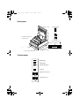
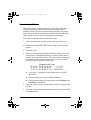
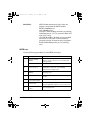
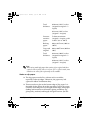
Printer parts
Printer cover
Control panel
POWER
ERROR
RECEIPT
OUT
JOURNAL
OUT
SLIP
RECEIPT
FEED
DIP switches are on
the bottom
SLIP FEED
Power connector
Interface connector
14
1
25
8
1
2
6
3
1
Power switch
Cover open button
Drawer connector
Display connector
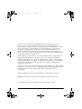
Control panel
POWER
ERROR
RECEIPT
OUT
POWER light
ERROR light
RECEIPT OUT light
JOURNAL
OUT
SLIP
RECEIPT
FEED
SLIP FEED
13
SLIP light
RECEIPT FEED button
SLIP FEED button
1
U925_eng.book
Page i
Thursday, July 25, 2002
9:15 AM
All rights reserved. No part of this publication may be reproduced, stored in a
retrieval system, or transmitted in any form or by any means, mechanical,
photocopying, recording, or otherwise, without the prior written permission of Seiko
Epson Corporation. No patent liability is assumed with respect to the use of the
information contained herein. While every precaution has been taken in the
preparation of this book, Seiko Epson Corporation assumes no responsibility for
errors or omissions. Neither is any liability assumed for damages resulting from the
use of the information contained herein.
Neither Seiko Epson Corporation nor its affiliates shall be liable to the purchaser of
this product or third parties for damages, losses, costs, or expenses incurred by
purchaser or third parties as a result of: accident, misuse, or abuse of this product or
unauthorized modifications, repairs, or alterations to this product, or (excluding the
U.S.) failure to strictly comply with Seiko Epson Corporation’s operating and
maintenance instructions.
Seiko Epson Corporation shall not be liable against any damages or problems arising
from the use of any options or any consumable products other than those designated
as Original Epson Products or Epson Approved Products by Seiko Epson
Corporation.
EPSON and ESC/POS are registered trademarks of Seiko Epson Corporation.
NOTICE: The contents of this manual are subject to change without notice.
Copyright © 1995, 1998 by Seiko Epson Corporation, Nagano, Japan.
i
U925_eng.book
Page ii
Thursday, July 25, 2002
9:15 AM
EMC and Safety Standards Applied
Product Name: TM-U925
Model Name: M62UA
The following standards are applied only to the printers that are so
labeled. (EMC is tested using the EPSON power supply.)
Europe:
CE Marking
Safety: EN60950
North America:
EMI: FCC/ICES-003 Class A
Safety: UL 1950/CSA C22.2 No. 950
Japan:
EMI:
Oceania:
EMC: AS/NZS 3548
VCCI Class A
WARNING
The connection of a non-shielded printer interface cable to this printer will invalidate
the EMC standards of this device.
You are cautioned that changes or modifications not expressly approved by SEIKO
EPSON Corporation could void your authority to operate the equipment.
ii
U925_eng.book
Page iii
Thursday, July 25, 2002
9:15 AM
CE Marking
The printer conforms to the following Directives and Norms
Directive 89/336/EEC
EN 55022 Class B
EN 55024
IEC 61000-4-2
IEC 61000-4-3
IEC 61000-4-4
IEC 61000-4-5
IEC 61000-4-6
IEC 61000-4-8
IEC 61000-4-11
Directive 90/384/EEC
EN45501
FCC Compliance Statement
For American Users
This equipment has been tested and found to comply with the limits for a Class A
digital device, pursuant to Part 15 of the FCC Rules. These limits are designed to
provide reasonable protection against harmful interference when the equipment is
operated in a commercial environment.
This equipment generates, uses, and can radiate radio frequency energy and, if not
installed and used in accordance with the instruction manual, may cause harmful
interference to radio communications. Operation of this equipment in a residential
area is likely to cause harmful interference, in which case the user will be required to
correct the interference at his own expense.
FOR CANADIAN USERS
This Class A digital apparatus complies with Canadian ICES-003.
Cet appareil numérique de la classe A est conforme à la norme NMB-003 du Canada.
iii
U925_eng.book
Page iv
Thursday, July 25, 2002
9:15 AM
GEREÄUSCHPEGEL
Gemäß der Dritten Verordnung zum Gerätesicherheitsgesetz
(Maschinenlärminformations- Verordnung-3. GSGV) ist der arbeitsplatzbezogene
Geräusch-Emissionswert kleiner als 70 dB(A) (basierend auf ISO 7779).
iv
U925_eng.book
Page v
Thursday, July 25, 2002
9:15 AM
Introduction
Features
The TM-U925 is a high-quality POS printer that can print on both slip and roll paper.
The printer has the following features:
❏
Wide slip paper capability (maximum characters per line: 88 with 7 x 9 font).
❏
Interface connector within the printer’s external dimensions.
❏
High throughput using bidirectional, minimum distance printing.
❏
Precision paper feeding at 0.176mm {1/144 inch}.
❏
Selectable receive buffer size (32 bytes or 2K bytes).
❏
Slip ejection.
❏
Command protocol based on the ECS/POS® standard.
❏
ASB (Automatic Status Back) function that automatically transmits changes in
printer status.
❏
EPSON® intelligent module connection.
❏
EPSON customer display series connection.
❏
Optional Magnetic Ink Character Recognition (MICR) reader that enables the
printer to perform reading and processing of MICR characters in addition to
printing endorsements.
Options and Accessories
❏
Magnetic Ink Character Recognition (MICR) reader (factory installed option)
❏
Direct connection customer displays, DM-D102 and DM-D203
❏
EPSON power supply unit, PS-170 (not required when the TM-U925 is
connected to an intelligent module)
❏
EPSON ribbon cassette, ERC-31 (P)
v
U925_eng.book
Page vi
Thursday, July 25, 2002
9:15 AM
About This Manual
Setting Up and Using
❏
Chapter 1 contains information on unpacking the printer, setting it up, running
the self test, setting the DIP switches, and adjusting the paper near end detector.
❏
Chapter 2 contains information on using the printer, including the optional
MICR reader.
❏
Chapter 3 contains troubleshooting information, including how to clean the
optional MICR reader.
Reference
❏
Chapter 4 contains specifications.
Notes, Cautions, and Warnings
Note:
Notes have important information and useful tips on the operation of your
printer.
CAUTION:
Cautions must be observed to avoid minor injury to yourself or
damage to your equipment.
WARNING:
Warnings must be followed carefully to avoid serious bodily
injury.
vi
U925_eng.book
Page 1
Thursday, July 25, 2002
9:15 AM
Contents
Chapter 1 Setting Up the Printer
Opening and Closing the Printer Cover . . . . . . . . . . . . . . . . . . . . . . . . . . . . . . . . . . . 1-1
Unpacking . . . . . . . . . . . . . . . . . . . . . . . . . . . . . . . . . . . . . . . . . . . . . . . . . . . . . . . . . . . . 1-2
Removing the protective material . . . . . . . . . . . . . . . . . . . . . . . . . . . . . . . . . . . . 1-2
Connecting the Printer to Your Computer . . . . . . . . . . . . . . . . . . . . . . . . . . . . . . . . . 1-3
Connecting the Printer to the Drawer Connector . . . . . . . . . . . . . . . . . . . . . . . . . . . 1-4
Connecting to a Direct Connection Display Module . . . . . . . . . . . . . . . . . . . . . . . . 1-5
Connecting the Power Supply . . . . . . . . . . . . . . . . . . . . . . . . . . . . . . . . . . . . . . . . . . . 1-6
Grounding the Printer . . . . . . . . . . . . . . . . . . . . . . . . . . . . . . . . . . . . . . . . . . . . . . . . . . 1-7
Installing the Ribbon Cassette . . . . . . . . . . . . . . . . . . . . . . . . . . . . . . . . . . . . . . . . . . . 1-8
IInstalling the Paper Roll . . . . . . . . . . . . . . . . . . . . . . . . . . . . . . . . . . . . . . . . . . . . . . . . 1-9
Self Test . . . . . . . . . . . . . . . . . . . . . . . . . . . . . . . . . . . . . . . . . . . . . . . . . . . . . . . . . . . . . . 1-11
Running the self test with roll paper . . . . . . . . . . . . . . . . . . . . . . . . . . . . . . . . . . 1-11
Running the self test with slip paper . . . . . . . . . . . . . . . . . . . . . . . . . . . . . . . . . . 1-12
Setting the DIP Switches . . . . . . . . . . . . . . . . . . . . . . . . . . . . . . . . . . . . . . . . . . . . . . . . 1-13
DIP switch functions . . . . . . . . . . . . . . . . . . . . . . . . . . . . . . . . . . . . . . . . . . . . . . . 1-13
Changing the DIP switch settings . . . . . . . . . . . . . . . . . . . . . . . . . . . . . . . . . . . . 1-14
Adjusting the Paper Near End Detector . . . . . . . . . . . . . . . . . . . . . . . . . . . . . . . . . . 1-16
Chapter 2 Using the Printer
Operating the Control Panel . . . . . . . . . . . . . . . . . . . . . . . . . . . . . . . . . . . . . . . . . . . . . 2-1
Buttons . . . . . . . . . . . . . . . . . . . . . . . . . . . . . . . . . . . . . . . . . . . . . . . . . . . . . . . . . . . 2-1
Indicator lights . . . . . . . . . . . . . . . . . . . . . . . . . . . . . . . . . . . . . . . . . . . . . . . . . . . . 2-2
Slip Paper Handling . . . . . . . . . . . . . . . . . . . . . . . . . . . . . . . . . . . . . . . . . . . . . . . . . . . . 2-3
Using the Power Switch Cover . . . . . . . . . . . . . . . . . . . . . . . . . . . . . . . . . . . . . . . . . . . 2-5
Using the MICR Reader (Option) . . . . . . . . . . . . . . . . . . . . . . . . . . . . . . . . . . . . . . . . 2-5
Reading MICR characters on personal checks . . . . . . . . . . . . . . . . . . . . . . . . . . 2-5
Chapter 3 Troubleshooting
Troubleshooting . . . . . . . . . . . . . . . . . . . . . . . . . . . . . . . . . . . . . . . . . . . . . . . . . . . . . . . 3-1
General problems . . . . . . . . . . . . . . . . . . . . . . . . . . . . . . . . . . . . . . . . . . . . . . . . . . 3-1
Printing problems . . . . . . . . . . . . . . . . . . . . . . . . . . . . . . . . . . . . . . . . . . . . . . . . . . 3-1
Paper handling problems . . . . . . . . . . . . . . . . . . . . . . . . . . . . . . . . . . . . . . . . . . . 3-3
Cleaning the MICR Mechanism . . . . . . . . . . . . . . . . . . . . . . . . . . . . . . . . . . . . . . . . . . 3-7
Hexadecimal Dump . . . . . . . . . . . . . . . . . . . . . . . . . . . . . . . . . . . . . . . . . . . . . . . . . . . . 3-8
vii
U925_eng.book
Page 2
Thursday, July 25, 2002
9:15 AM
Chapter 4 Reference Information
Printing Specifications . . . . . . . . . . . . . . . . . . . . . . . . . . . . . . . . . . . . . . . . . . . . . . . . . 4-1
Character Specifications . . . . . . . . . . . . . . . . . . . . . . . . . . . . . . . . . . . . . . . . . . . . . . . 4-2
Ribbon Specifications . . . . . . . . . . . . . . . . . . . . . . . . . . . . . . . . . . . . . . . . . . . . . . . . . . 4-3
MICR Specifications (Option) . . . . . . . . . . . . . . . . . . . . . . . . . . . . . . . . . . . . . . . . . . . . 4-3
MICR use . . . . . . . . . . . . . . . . . . . . . . . . . . . . . . . . . . . . . . . . . . . . . . . . . . . . . . . . . 4-4
Notes on MICR use . . . . . . . . . . . . . . . . . . . . . . . . . . . . . . . . . . . . . . . . . . . . . . . . 4-5
Paper Specifications . . . . . . . . . . . . . . . . . . . . . . . . . . . . . . . . . . . . . . . . . . . . . . . . . . . 4-5
Electrical Characteristics . . . . . . . . . . . . . . . . . . . . . . . . . . . . . . . . . . . . . . . . . . . . . . . 4-10
Reliability . . . . . . . . . . . . . . . . . . . . . . . . . . . . . . . . . . . . . . . . . . . . . . . . . . . . . . . . . . . . 4-12
Environmental Conditions . . . . . . . . . . . . . . . . . . . . . . . . . . . . . . . . . . . . . . . . . . . . . . 4-12
viii
U925_eng.book
Page 1
Thursday, July 25, 2002
9:15 AM
Chapter 1
Setting Up the Printer
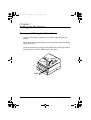
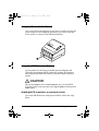
Opening and Closing the Printer Cover
Use these instructions whenever you need to open or close the
printer.
Open the printer by pushing the cover-open button and then lifting
the printer cover.
Close the printer by pressing on the indentation on the right side of
the printer cover until it audibly clicks into place.
OPEN 2
CLOSE
OPEN 1
Setting Up the Printer 1-1
U925_eng.book
Page 2
Thursday, July 25, 2002
9:15 AM
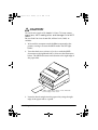
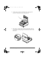
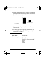
Unpacking
The illustration below shows the items included for the standard
specification printer.
Ribbon
Paper roll
Printer
Hexagonal lock screws
Caution label
Power switch
cover
See the note on page 1-3 for information about the hexagonal lock screws.
See the power switch cover section in Chapter 2 for information about the cover.
See the slip paper handling section in Chapter 2 for information about the label.
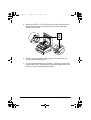
Removing the protective material
The printer is protected during shipping by a piece of protective
material that must be removed before you turn on the printer.
Pull out the protective material and remove it from the printer as
shown below.
1-2 Setting Up the Printer
U925_eng.book
Page 3
Thursday, July 25, 2002
9:15 AM
Store the protective material with the other packing materials and
use it when transporting your printer.
Connecting the Printer to Your Computer
Follow the procedures below only when you use the printer as a
single unit (not connected to an intelligent module). When you use
the printer with the intelligent module, see the IM-403/405 User's
Guide for details.
You need an appropriate interface cable to connect your computer
to the printer's built-in interface.
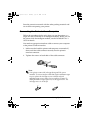
1. Make sure that both the printer and computer are turned off;
then attach the cable connector securely into the printer's
interface connector.
2. Tighten the screws on both sides of the cable connector.
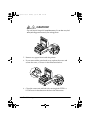
Note:
Your printer comes with inch-type hexagonal lock screws
installed. To use an interface cable that requires millimeter-type
screws, replace the inch-type screws with the enclosed
millimeter-type screws using a hex screwdriver (5 mm). To
distinguish the two types of screws, see the figure below. The
inch-type screw is on the left.
Setting Up the Printer 1-3
U925_eng.book
Page 4
Thursday, July 25, 2002
9:15 AM
3. Attach the other end of the cable into the computer.
4. Plug the power supply's power cord into an electrical outlet.
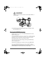
Connecting the Printer to the Drawer Connector
Follow the procedures below to connect a drawer to the printer
only when you use the printer as a single unit (not connected to an
intelligent module). When you use the printer with the intelligent
module, see the IM-403/405 User's Guide for details.
You need an appropriate drawer kick-out cable to connect your
drawer to the printer. See Chapter 4 for more information about the
drawer interface.
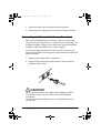
1. Make sure that the printer is turned off.
2. Plug the cable connector into the printer's drawer kick-out
connector until it clicks.
CAUTION:
Be sure not to connect this cable to the display module
connector, which is on the other side of the interface
connector.
Do not connect a telephone line to the drawer kick-out
connector.
1-4 Setting Up the Printer
U925_eng.book
Page 5
Thursday, July 25, 2002
9:15 AM
Note:
To remove the cable connector, squeeze the connector's clip and pull
it out.
Connecting to a Direct Connection Display Module
If you are using the printer as a single unit (not connected to an
intelligent module) and you plan to connect a direct connection
display module, follow the steps below. When you use the printer
with the intelligent module, see the IM-403/405 User's Guide for
details.
1. Make sure that the printer is turned off.
2. Plug the cable connector (provided with the direct connection
display module) securely into the printer's display module
connector until it clicks.
CAUTION:
Do not connect this cable to the drawer kick out connector,
which is on the other side of the interface connector.
Also do not connect a telephone line to the display module
connector.
Setting Up the Printer 1-5
U925_eng.book
Page 6
Thursday, July 25, 2002
9:15 AM
Note:
To remove the cable, squeeze the connector and pull it out.
Connecting the Power Supply
When the printer is used as a single unit, not connected to an
intelligent module, use the optional EPSON PS-170 power supply
for your printer.
When the printer is connected to an intelligent module, the power
is supplied by the intelligent module. See the IM-403/405 User's
Guide for details.
CAUTION:
Make sure that you use the EPSON PS-170 power supply.
When connecting or disconnecting the power supply from
the printer, make sure that the power supply is not plugged
into an electrical outlet.
1. Make sure that the printer’s power switch is turned off, and the
power supply’s power cord is unplugged from the electrical
outlet.
2. Check the label on the power supply to make sure that the
voltage required by the power supply matches that of your
electrical outlet.
CAUTION:
If the power supply's rated voltage and your outlet's
voltage do not match, contact your dealer for
assistance. Do not plug in the power cord.
1-6 Setting Up the Printer
U925_eng.book
Page 7
Thursday, July 25, 2002
9:15 AM
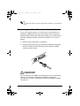
3. Plug in the power supply's cable as shown below. Notice that
the flat side of the plug faces down.
Note:
To remove the DC cable connector, make sure that the power
supply's power cord is unplugged; then grasp the connector at the
arrow and pull it straight out.
Grounding the Printer
When you use the printer as a single unit (not connected to an
intelligent module), you need an appropriate ground wire to
ground your printer.
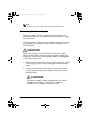
1. Make sure that the printer is turned off.
2. Connect the ground wire to the printer using the FG screw on
the bottom of the printer, as shown.
Setting Up the Printer 1-7
U925_eng.book
Page 8
Thursday, July 25, 2002
9:15 AM
Installing the Ribbon Cassette
Use Epson ERC-31 (P) ribbon cassette for your printer.
CAUTION:
Never turn the ribbon cassette's feed knob in the opposite
direction of the arrow marked on the cassette.
1. Turn on the printer and open the printer cover.
2. Turn the ribbon cassette's knob two or three times in the
direction of the arrow to take up any slack in the ribbon.
Tab
3. Insert the ribbon cassette in the printer and rotate the cassette's
knob two or three more times as shown below. This is
necessary to place the ribbon in the correct position.
1-8 Setting Up the Printer
U925_eng.book
Page 9
Thursday, July 25, 2002
9:15 AM
Make sure that the ribbon is installed in front of the print head
without wrinkles or creases. If it is hard to see, open the print
head cover as described in Chapter 3.
If the ribbon is not installed correctly, remove the cassette as
described below and repeat steps 2 and 3 above.
Note:
To remove the ribbon cassette, grasp the ribbon cassette's tab and
pull it out of the printer. See the illustration in step 2 above for the
location of the tab.
IInstalling the Paper Roll
Use a paper roll that matches the printer's specifications. See
Chapter 4 for paper specifications.
1. Make sure that the edge of the paper is straight, as shown on
the left side of the illustration.
2. Turn on the printer and open the printer cover.
Setting Up the Printer 1-9
U925_eng.book
Page 10
Thursday, July 25, 2002
9:15 AM
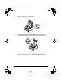
3. Insert a paper roll, as shown below.
Correct
Wrong
4. Insert the tip of the paper into the paper inlet and push it in
until it is automatically detected and fed into the printer.
5. Tear off the paper on the cutter. If the paper was not fed far
enough, press the RECEIPT FEED button to feed additional
paper.
1-10 Setting Up the Printer
U925_eng.book
Page 11
Thursday, July 25, 2002
9:15 AM
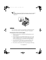
Note:
To remove the paper roll, hold down the paper release lever (marked
PRESS) and pull out the paper roll in the direction shown in the
illustration.
Paper release lever
Self Test
The self test lets you know if your printer is operating properly.
You can run the self test with either roll paper or slip paper.
Running the self test with roll paper
1. Make sure the printer is turned off and the printer cover is
closed properly.
2. While holding down the RECEIPT FEED button, turn on the
printer to begin the self test. The self test prints the printer
settings and then pauses. (The RECEIPT OUT light blinks.)
3. Press the RECEIPT FEED button to continue printing. The
printer prints a pattern using the built-in character set.
4. The self test automatically ends after printing the following:
*** completed ***
Setting Up the Printer 1-11
U925_eng.book
Page 12
Thursday, July 25, 2002
9:15 AM
The printer is ready to receive data as soon as it completes the self
test.
Note:
If you want to pause the self test manually, press the RECEIPT
FEED button. Then press the RECEIPT FEED button to continue
the self test.
Running the self test with slip paper
Note:
Be sure to install the paper roll to prevent slip paper jams.
1. Make sure the printer is turned off and the printer cover is
closed properly.
2. While holding down the SLIP FEED button, turn on the printer
to begin the self test. (The SLIP light blinks.)
3. Feed a sheet of slip paper into the printer. The printer loads the
paper automatically, prints the printer settings, and then ejects
the paper. (The SLIP light blinks.)
4. Remove the paper from the printer and feed another sheet of
slip paper into the printer to print characters from the character
table. Continue to feed slip paper into the printer until the self
test prints the following:
***completed***
The printer is ready to receive data as soon as it completes the self
test.
Note:
If you want to pause the self test manually, press the SLIP FEED
button. Press the SLIP FEED button to continue the self test.
1-12 Setting Up the Printer
U925_eng.book
Page 13
Thursday, July 25, 2002
9:15 AM
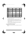
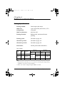
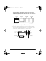
Setting the DIP Switches
DIP switch functions
Your printer has two sets of DIP switches. The functions of the
switches are shown in the tables below.
Set 1
SW
Function
ON
OFF
Factory
settings
1-1
Data word length
7 bits
8 bits
OFF
1-2
Parity
Enabled
Disabled
OFF
1-3
Parity selection
Even
Odd
OFF
1-4
OFF
Transmission speed selection (See the table below)
1-5
OFF
1-6
Customer display
connection*
Connected
Not connected
OFF
1-7
Data receive error
Ignored
Prints ?
OFF
1-8
Handshaking
XON/XOFF
DTR/DSR
OFF
* Effective when a direct connection display module is connected to the printer's
display module connector.
Transmission Speed
Transmission Speed (BPS)
1-4
1-5
1200
ON
ON
2400
OFF
ON
4800
ON
OFF
9600
OFF
OFF
Setting Up the Printer 1-13
U925_eng.book
Page 14
Thursday, July 25, 2002
9:15 AM
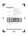
Set 2
SW
Function
ON
OFF
Factory
settings
2-1
Auto line feed
Always enabled
Always disabled
OFF
2-2
Receive buffer
32 bytes
2048 bytes
OFF
2-3
Font selection
(default)
9x9
7x9
OFF
2-4
Carriage speed
(default for paper
roll printing)
Low
High
OFF
2-5
Handshaking (BUSY
condition)
Receive buffer-full
Off-line or
receive buffer-full
OFF
2-6
Internal use
Fixed
-
ON
2-7
I/F pin 6 reset signal
Enabled
Disabled
OFF
2-8
I/F pin 25 reset signal
Enabled
Disabled
OFF
Notes:
1. When pin 6 of the interface connector is used for the reset signal, the printer is
reset at MARK on the RS-232C level.
2. When pin 25 of the interface connector is used for the reset signal, the printer
is reset at SPACE on the RS-232C level or at HIGH on the TTL level.
3. DIP switches excluding switch 2-1 (Auto line feed) and switches 2-7 and 2-8
(interface reset signal) are effective only while the printer power is turned on.
If the DIP switch setting is changed after the printer power is turned on, the
change is not effective.
4. If DIP switch 2-7 or 2-8 is on while the printer power is turned on, the printer
may be reset, depending on the signal state. DIP switches should not be
operated while the printer power is turned on.
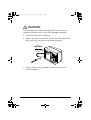
Changing the DIP switch settings
If you need to change settings, follow the steps below to make your
changes:
1-14 Setting Up the Printer
U925_eng.book
Page 15
Thursday, July 25, 2002
9:15 AM
CAUTION:
Turn off the printer while removing the DIP switch cover to
prevent an electric short, which can damage the printer.
1. Make sure the printer is turned off.
2. Remove the screw from the DIP switch cover. Then take off the
DIP switch cover, as shown in the illustration below.
DSW
DSW1 DSW2
DSW2
3. Set the switches using a pointed tool, such as tweezers or a
small screwdriver.
Setting Up the Printer 1-15
U925_eng.book
Page 16
Thursday, July 25, 2002
9:15 AM
4. Replace the DIP switch cover by inserting it upward and
sliding it to the left as shown below. Then secure it with the
screw.
DSW DSW2
1
2
5. The new settings take effect when you turn on the printer.
Adjusting the Paper Near End Detector
The paper near end detector detects when the paper is almost gone
by measuring the diameter of the paper roll. Software programs
can use the ESC c 4 command to stop printing when the paper is
almost gone.
If you want to change the amount of paper remaining when the
printer stops printing, follow the steps below to adjust the paper
near end detector.
Note:
The printer also has a paper end-sensor that stops the printer at the
very end of a roll. This sensor cannot be turned off by software.
1. Open the printer cover and remove the paper roll.
1-16 Setting Up the Printer
U925_eng.book
Page 17
Thursday, July 25, 2002
9:15 AM
2. Determine the point on the paper roll at which you want the
paper roll end detection to be triggered. Then measure the
distance A shown in the illustration.
distance A
Note:
There may be some difference between the measured distance A and
the actual sensing position.
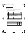
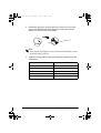
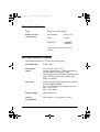
3. Find the corresponding adjustment position number from the
table below.
Distance A
Adjustment position number
10 mm (0.39 inch)
#1
8 mm (0.32 inch)
#2
6 mm (0.24 inch)
#3
4 mm (0.16 inch)
#4
2 mm (0.08 inch)
#5
Setting Up the Printer 1-17
U925_eng.book
Page 18
Thursday, July 25, 2002
9:15 AM
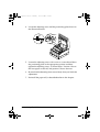
4. Locate the adjusting screw and the positioning plate shown in
the illustration below.
#5
#4
#3
#2
#1
Loosen
Secure
5. Loosen the adjusting screw with a coin or a screwdriver.Move
the positioning plate to the appropriate position and then
tighten the adjusting screw, as shown below. Position 1 leaves
the least paper on the roll, and position 5 leaves the most
6. Be sure that the detecting lever moves freely after you finish the
adjustment.
7. Re-install the paper roll, as described earlier in this chapter.
1-18 Setting Up the Printer
U925_eng.book
Page 1
Thursday, July 25, 2002
9:15 AM
Chapter 2
Using the Printer
Operating the Control Panel
You can control the basic paper feeding operations of the printer
with the buttons on the control panel. The indicator lights help you
monitor the printer’s status.
POWER
ERROR
RECEIPT
OUT
JOURNAL
OUT
SLIP
RECEIPT
FEED
SLIP FEED
Buttons
These buttons can be disabled by the ESC c 5 command, but they
work whenever the printer cover is open, even if they have been
disabled by the ESC c 5 command.
RECEIPT FEED
Press the RECEIPT FEED button once to advance receipt paper one
line. You can also hold down RECEIPT FEED to feed receipt paper
continuously.
Using the Printer 2-1
U925_eng.book
Page 2
Thursday, July 25, 2002
9:15 AM
SLIP FEED
You cannot load slip paper using this button. Slip paper can be
loaded only by selecting slip paper with a command and then
inserting the paper. When the printer is in the slip paper mode (the
SLIP light is on or blinking) and slip paper is inserted, you can press
the SLIP FEED button once to advance slip paper one line or hold
down SLIP FEED to feed slip paper continuously.
Indicator lights
The control panel lights provide information on printer conditions.
POWER (green)
The POWER light is on when the printer power is on.
ERROR (red)
The ERROR light is on or blinking when the printer is not ready to
print.
The ERROR light is on (not blinking) under the following
conditions:
❏ When the printer is first turned on or reset through the
interface. The light goes off as soon as the printer is initialized.
❏ When the printer cover is open.
❏ When the printer is at or near the end of a roll of paper.
The ERROR light blinks under the following conditions:
❏ When the print head is overheated. If this happens, the printer
waits until the print head cools and then resumes printing.
❏ When an error occurs.
For more information on error conditions, see Chapter 4,
“Troubleshooting.”
2-2 Using the Printer
U925_eng.book
Page 3
Thursday, July 25, 2002
9:15 AM
RECEIPT OUT (red)
The RECEIPT OUT light is on (not blinking) when the paper roll is
not installed or is at or near the end. The RECEIPT OUT light blinks
after the self test prints the printer settings on the roll paper.
SLIP (green)
The SLIP light is on or blinking while the printer is in slip paper
mode.
The SLIP light blinks while the printer is waiting for slip paper to be
inserted or removed.
Slip Paper Handling
Use only slip paper that matches the printer’s specifications. See
Paper Specifications in Chapter 4.
Note:
Be sure to install a paper roll in the printer even if you plan to print
only on slip paper. This will prevent paper jams. You can also
prevent paper jams by using slip paper that is flat and has no
wrinkles, creases, or folds.
1. Send appropriate control commands from the computer to
print on slip paper.
2. When the SLIP light blinks, insert the slip paper into the slip
paper inlet using the right edge of the slip paper inlet as a
guide.
Make sure you insert the slip paper into the inlet as far as it will
go (i.e., insert the slip paper up to the mark on the left side of
the printer).
The paper is automatically drawn into the printer and printing
begins.
Using the Printer 2-3
U925_eng.book
Page 4
Thursday, July 25, 2002
9:15 AM
Note:
Place the caution label, which reminds you how to insert slip paper,
on the printer as shown in the illustration below, if necessary.
CAUTION:
Be sure to put the caution label exactly in the position shown.
If you put it another place, such as over the slip paper inlet,
the printer may be damaged.
2-4 Using the Printer
U925_eng.book
Page 5
Thursday, July 25, 2002
9:15 AM
Using the Power Switch Cover
You can use the enclosed power switch cover to make sure that the
power switch is not accidentally pressed. If you want to use this
cover, install it as shown in the illustration below.
Using the MICR Reader (Option)
If your printer has the factory installed optional Magnetic Ink
Character Recognition (MICR) reader that enables the printer to
read and process MICR characters on personal checks, read this
section.
CAUTION:
Be sure the paper roll is installed before you use the MICR
function. Even when you are not using roll paper, this prevents
paper jams.
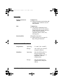
Reading MICR characters on personal checks
To use the MICR function with personal checks, follow the steps
below:
Using the Printer 2-5
U925_eng.book
Page 6
Thursday, July 25, 2002
9:15 AM
CAUTION:
Do not insert checks with staples in them. This may cause
paper jams, MICR reading errors, and damage to the MICR
head.
Be sure that the checks are flat, without curls, folds, or
wrinkles.
1. Wait until the computer sends the FS a 0 command to the
printer, causing it to enter the MICR mode. The SLIP light
blinks.
2. Turn the check over so that it is face down with the MICR
characters on the righthand side, as shown in the illustration
below. The MICR characters must be next to the right edge of
the paper inlet.
MICR characters must be on the underside
of this edge of the check
3. Insert the check straight into the paper inlet, using the right
edge of the paper inlet as a guide.
2-6 Using the Printer
U925_eng.book
Page 7
Thursday, July 25, 2002
9:15 AM
4. Insert the check as far as it will go. The printer will detect the
check and start drawing it in.
5. When the printer starts drawing it in, let go of the check
immediately. The SLIP light quits blinking but stays on.
6. When printing and MICR reading are finished, the printer
ejects the check and the SLIP light starts blinking again.
7. Remove the check by pulling it straight up; do not pull it at an
angle. The SLIP light goes off.
See Chapter 3 to find out how to clean the MICR mechanism,
and see Chapter 4 for further details on using the MICR reader.
Using the Printer 2-7
U925_eng.book
Page 8
Thursday, July 25, 2002
2-8 Using the Printer
9:15 AM
U925_eng.book
Page 1
Thursday, July 25, 2002
9:15 AM
Chapter 3
Troubleshooting
Troubleshooting
This chapter gives solutions to some of the more common printer
problems.
General problems
The lights on the control panel do not come on.
Make sure that the power supply cables are correctly plugged into
the printer, the power unit, and to the power outlet.
Make sure that power is supplied to the power outlet. If the outlet
is controlled by a switch or timer, use another outlet.
Printing problems
The ERROR light is on (not blinking) and nothing is printed.
If the RECEIPT OUT light is on, the paper roll is not installed or
is at or near the end. Install a new paper roll in the printer. See
Chapter 1 for instructions.
If the RECEIPT OUT light is off, make sure that the printer cover is
properly closed. Press the round indentation on the printer cover
until the cover audibly clicks into place. You may not be able to
close the printer cover if one or both of the OPEN <-> LOCK levers
is open. See the illustration on page 3-7 to help you close the levers.
Troubleshooting 3-1
U925_eng.book
Page 2
Thursday, July 25, 2002
9:15 AM
The ERROR light is blinking and the printer does not print.
First, turn off the printer and check for a paper jam. (See the paper
jam description on page 3-3.)
If there is no paper jam and the printer has been printing for quite a
while, the print head may be overheated. If the print head is
overheated, the printer will resume printing when the head has
cooled (usually within two or three minutes).
If there is no paper jam and the print head is not overheated, turn
off the printer and turn it back on after about 10 seconds. If the
ERROR light is still flashing, contact a qualified service person.
The ERROR light is off, but nothing is printed.
Try to run the self test to check that the printer works properly. See
the self test instructions in Chapter 1 to run the self test. If the self
test does not work, contact your dealer or a qualified service
person.
If the self test works properly, check the following:
1. Check the connection at both ends of the interface cable
between the printer and the computer. Also make sure that this
cable meets the specifications for both the printer and the
computer.
2. The data transmission settings may be different between the
printer and computer. Make sure that the printer’s DIP switch
settings for data transmission are the same as the computer’s.
You can print the printer’s interface settings using the self test.
If the printer still does not print, contact your dealer or a qualified
service person.
3-2 Troubleshooting
U925_eng.book
Page 3
Thursday, July 25, 2002
9:15 AM
The printer sounds like it is printing, but nothing is printed.
The ribbon cassette may not be installed properly. See the
instructions in Chapter 1.
The ribbon may be worn out. Replace the ribbon cassette as
described in Chapter 1.
The printout is faint.
The ribbon may be worn out. Replace the ribbon cassette as
described in Chapter 1.
A line of dots is missing in the printout.
The print head may be damaged. Stop printing and contact your
dealer or a qualified service person.
Paper handling problems
Slip paper or personal checks are not fed properly or become jammed
frequently.
The paper roll is not installed properly. Remove and reinstall the
paper roll as described in Chapter 1.
Paper is jammed inside the printer.
To clear a paper jam, follow the steps below:
1. Turn the printer off and open the printer cover.
Troubleshooting 3-3
U925_eng.book
Page 4
Thursday, July 25, 2002
9:15 AM
2. Cut the paper as shown in the illustration, using a pair of
scissors or a knife; then remove the paper roll.
cut
3. If the paper is caught in the automatic cutter blade, open the
cutter blade by rotating the gear in the direction shown in the
illustration.
3-4 Troubleshooting
U925_eng.book
Page 5
Thursday, July 25, 2002
9:15 AM
4. Move the OPEN <-> LOCK lever on each side of the printer in
the direction shown in the illustration; the cutter unit then
opens automatically.
OPEN
LOCK
5. Pull the paper out gently. If the paper tears, make sure you
remove any remaining pieces.
6. If you encounter difficulty in clearing a paper jam, remove the
print head cover by loosening the screw on the right side of the
cover, as shown in the illustration below.
Troubleshooting 3-5
U925_eng.book
Page 6
Thursday, July 25, 2002
9:15 AM
CAUTION:
Do not touch the print head because it can be very hot
after printing continuously for a long time.
7. Remove any paper from inside the printer.
8. If you removed the print head cover, replace the cover and
secure the screw, as shown in the illustration below.
9. Close the cutter unit and lock it by moving both OPEN <->
LOCK levers in the direction shown in the illustration.
3-6 Troubleshooting
U925_eng.book
Page 7
Thursday, July 25, 2002
9:15 AM
CAUTION:
Make sure you lock the cutter unit with both OPEN <->
LOCK levers.
OPEN
LOCK
10. Install the paper roll following the steps in Chapter 1; then
close the printer cover.
Cleaning the MICR Mechanism
Foreign matter on any part of the MICR mechanism can cause
MICR reading errors.
Cleaning the MICR mechanism is simple. First, send the cleaning
command (FS c) to the printer. Then insert the special MICR
cleaning paper the same way you insert a check.
The printer feeds the paper through, cleaning the MICR head,
roller, and paper path.
Perform this cleaning once a month or after every 6,000 checks .
Use a special MICR cleaning paper such as the KIC Products
PRESAT brand check reader cleaning card or the equivalent. The
size should be 63 x 152 mm (2.48 x 5.98”). (USA only)
Troubleshooting 3-7
U925_eng.book
Page 8
Thursday, July 25, 2002
9:15 AM
Hexadecimal Dump
This feature allows experienced users to see exactly what data is
coming to the printer. This can be useful in finding software
problems. When you turn on the hex dump function, the printer
prints all commands and other data in hexadecimal format along
with a guide section to help you find specific commands.
To use the hex dump feature, follow these steps:
1. After you make sure that the printer is off, open the cover.
2. Hold down the RECEIPT FEED button while you turn on the
printer.
3. Close the cover.
4. Run any software program that sends data to the printer. The
printer prints “Hexadecimal Dump” and then all the codes it
receives in a two-column format. The first column contains the
hexadecimal codes and the second column gives the ASCII
characters that correspond to the codes.
Hexadecimal Dump
1B 21 00 1B 26 02 40 40 : . ! . . & . @ @
1B 25 01 1B 63 34 00 1B : . % . . c4 . .
41 42 43 44 45 46 47 48 : ABCDEFGH
❏
A period (.) is printed for each code that has no ASCII
equivalent.
❏ Control codes are printed in bold for emphasis.
❏ During the hex dump all commands except DLE EOT and
DLE ENQ are disabled.
5. Open the cover to set the printer off line so that it will print the
last line.
6. Close the cover and turn off the printer or reset it to turn off the
hex dump mode.
3-8 Troubleshooting
U925_eng.book
Page 1
Thursday, July 25, 2002
9:15 AM
Chapter 4
Reference Information
Printing Specifications
Printing method:
Serial impact dot matrix
Head wire
configuration:
9-pin vertical line, 0.353 mm {1/72”}
wire pitch
Head wire diameter:
0.29 mm {.01"}
Printing direction:
Bidirectional, minimum distance
printing
Printing speed:
See table on page 4-2.
Characters per line:
See table on page 4-2.
Characters per inch:
See table on page 4-2.
Print modes:
See the print modes table below.
Print modes
Paper roll
Print
mode
Printing
speed*1
Print head
energizing
time
Normal
High
Normal
Low
speed
Low
Normal
Depends
on DIP
SW 2-4
Copy
Low
Copy (long)
--
Default
status
Slip paper
Switching*2
Default
status
Switching*2
Possible
--
Possible
Possible
--
Possible
Possible
Selected
Possible
Note:
*1 The printer automatically goes to low speed mode during bit image printing,
regardless of the type of selected paper.
*2 Print mode can be changed using the GS E command.
Reference Information 4-1
U925_eng.book
Page 2
Thursday, July 25, 2002
9:15 AM
Character Specifications
Number of characters:
Alphanumeric characters: 95
International characters: 32
Extended graphics: 128 × 8 pages
(including space pages)
9 × 9 3-dot spacing (in half dot units)
Character structure:
7 × 9 2-dot spacing (in half dot units)
Larger spacing can be set by using
ESC SP.
See the table below.
Character size:
Characters per inch, characters per second,
characters per line, character size
Character
structure * 1
Character
spacing
(half dots)
CPI * 2
9x9
3 dots
7x9
2 dots
CPS * 3
CPL * 4
Slip
paper
Character size
(width x height)
High
Low
Paper
roll
12.5
233
200
30
66
1.6 x 3.1 mm
{.06" x .12"}
16.7
311
267
40
88
1.3 x 3.1 mm
{.05" x .12"}
*1 Horizontal dots x vertical dots
*2 CPI: Characters Per Inch (number of characters per 25.4 mm)
*3 CPS: Characters Per Second (number of characters per second)
*4 CPL: Characters Per Line
4-2 Reference Information
U925_eng.book
Page 3
Thursday, July 25, 2002
9:15 AM
Ribbon Specifications
Type:
Exclusive cassette ribbon
Ribbon cassette
specifications:
Part number
ERC-31 (P)
Color
Purple
Ribbon life
7,000,000
characters
(when one character consists of
18 dots)
MICR Specifications (Option)
The MICR mechanism is a factory-installed option.
Available fonts:
E-13B, CMC7
Recognition
rating:
98% or more at 25°C (75°F)
Rating = ([total checks – number misread or
not identified]/total checks) × 100
Check paper tested is EPSON standard check
paper. Checks must be flat, without curls,
folds, or wrinkles.
Paper type:
Normal check paper with thickness of 0.09 to
0.2mm {0.0035 to 0.0079”}
Size: 68 to 102mm × 152 to 210 mm {2.68 to
4.02 × 2.98 to 8.27”}
Mass: 70 to 90 Kg.
Ripple voltage:
300 mVpp or less
Current
consumption:
Mean approx. 2.3A (Approx. 1.4 sec)
Reference Information 4-3
U925_eng.book
Page 4
Thursday, July 25, 2002
Reliability:
9:15 AM
MICR reader mechanism (only when the
printer is used with the MICR reader):
MCBF: 160,000 passes
Life: 240,000 passes
(One pass: from reading characters to printing
endorsements on a U.S.A. personal check (152
mm {5.98”} long)
(The MICR reader is defined to have reached
the end of its life when it cannot function
properly because of the main parts (magnetic
head, head holding roller, etc.) of wearing
out.)
MICR use
Use the following procedure to read MICR characters.
User Operation
Printer Operation
Transmits FS a 0
<00>H.
Mechanically switches to MICR mode and
waits for a personal check to be loaded. The
SLIP light blinks.
(Transmits DLE ENQ 3.)
(when the check waiting state is canceled)
2
Inserts a check.
Detects the check, lights the SLIP light, and
reads MICR characters. After reading,
transmits the reading results.
3
(Transmits FS a 0
<00>H.)
(Re-reads the check and transmits the
reading result.)
4
Transmits FS a 1.
Loads the check paper to the print starting
position.
5
Transmits endorsement printing data.
Prints data and feeds paper.
6
Transmits FF.
After printing, ejects paper.
The SLIP light blinks until the check is removed.
7
Removes the check
paper.
The SLIP light blinks.
1
4-4 Reference Information
U925_eng.book
Page 5
Thursday, July 25, 2002
9:15 AM
Notes on MICR use
❏ Personal checks are fed in the forward direction only.
❏ The paper roll must be loaded correctly before selecting MICR
function. Otherwise, check paper is not fed properly.
❏ The check waiting state is canceled using DLE ENQ 3.
❏ After a personal check is ejected, the SLIP light comes on and
the printer does not proceed to the next operation until the
check is removed.
❏ The check waiting time and the interval from when a check is
inserted to when the operation starts can be set using ESC f.
❏ To check the MICR function status exactly, use DLE EOT BS 1.
❏ Remove ejected personal checks by pulling them upward. Do
not pull them out in the horizontal direction.
Paper Specifications
Paper feed method:
Friction feed
Paper feed pitch:
Default 4.23 mm {1/6 inch}
Can be set in units of 0.353 mm {1/144
inch} by the ESC 3 and ESC J
commands.
Paper feed speed:
Approx. 60.3 ms/line (4.23 mm {1/6
inch} feeding)
Approx. 86.36 mm/second {3.4
inches/second} (continuous feeding)
Paper size:
Paper roll (single-ply)
Reference Information 4-5
U925_eng.book
Page 6
Thursday, July 25, 2002
9:15 AM
Size:
Width 69.5 mm ± 0.5 mm
{2.74" ± 0.02"}
Maximum 83 mm {3.27"}
outside
diameter:
Thickness:
0.06 to 0.09 mm {.0024 to
.0035"}
Mass:
52.3 to 64.0 g/m {13.9 to
17 lbs} (JIS P8124) (45 to
55 Kg {20.41 to 24.94 lbs}/
1000 sheets/788 mm ×
1091mm {31.02" × 42.95"}
Paper roll
inside
diameter:
10 mm {0.39"} or more
2
Slip paper
Paper type: Normal paper
Carbon copy paper
Pressure sensitive paper
Total
thickness:
0.09 to 0.36 mm {.0035 to
.0141"}
See the Copy capability and paper
thickness portion on the next page for
more information.
Size
(W × L):
4-6 Reference Information
70 mm × 70 mm to 210
mm × 297 mm (A4 size)
{2.76" × 2.76" to 8.27" ×
11.69"}
U925_eng.book
Page 7
Thursday, July 25, 2002
9:15 AM
Ambient temperature and copy
capability
Copy capability is greatly influenced
by the ambient temperature, so
printing must be performed under the
conditions described in the table
below.
Relationship between ambient temperature and
number of copies
Number of copies
Ambient temperature (print mode)
Original + 4 copies
20° to 40°C {68° to 104°F} (copy mode)
Original + 1 to 3 copies
5° to 40°C {41° to 104°F} (copy mode)
Copy
capability
and paper
thickness:
Normal paper (singleply): 0.09 to 0.2 mm {.0035
to .0079"}
Carbon copy paper
combination:
5 sheets maximum
(original + 4 copies, at 20°
to 40°C {68° to 104°F}
Backing
paper:
0.06 to 0.15 mm {.0023 to
.0059"}
Copy and
original:
0.04 to 0.07 mm {.0015 to
.0028"}
Carbon
paper:
Approx. 0.035 mm
{.0014"}
Reference Information 4-7
U925_eng.book
Page 8
Thursday, July 25, 2002
9:15 AM
Total
thickness:
0.30 mm {.0118"} or less
(original to original + 3
copies)
0.36 mm {.014"} or less
(original + 4 copies)
Pressure
sensitive
paper:
5 sheets maximum
(original + 4 copies, at 20°
to 40°C {68° to 104°F}
Backing
paper:
0.06 to 0.15 mm {.0023 to
.0059"}
Copy and
original:
0.06 to 0.075 mm {.0023 to
.003"}
Total
thickness:
0.24 mm {.0094"} or less
(original to original + 3
copies)
0.30 mm {.0118"} or less
(original + 4 copies)
Note:
When using multi-ply paper that consists of an original and three
copies, be sure to print with a 9 × 9 font. If a 7 × 9 font is used, some
characters on some of the copies may not be readable.
Notes on slip paper
❏ The slip paper must be flat, without curls or wrinkles,
especially at the top edges. Otherwise, the paper may rub
against the ribbon and become dirty.
❏ There must be no glue on the bottom edge of slip paper. It is
desirable for the glue to be on the top edge. Choose slip paper
carefully when the glue is on the right or left edge, since paper
feeding and insertion are affected by gluing conditions (e.g.,
glue quality, method, and length) and glue location. (See the
4-8 Reference Information
U925_eng.book
Page 9
Thursday, July 25, 2002
9:15 AM
illustration below.) Be especially careful when slip paper is
wide and has the glue on the right or left edge, since it may not
feed in a straight line.
OK to use
Do not use
Use carefully
Use carefully
Paper feed direction
Glued area
Slip paper glued area
❏ Since the slip insertion detector uses a photo detector, paper
that has holes at the detector position, or is translucent, must
not be used. (See the illustration on the next page.)
3mm (.12")
Form stopper
position
2mm (.08")
14.6mm
(.58")
Sub-slip feed
roller position
Slip insertion
sensor position
Slip insertion sensor position
Reference Information 4-9
U925_eng.book
Page 10
Thursday, July 25, 2002
9:15 AM
❏ Since the slip ejection detector uses a reflective photo detector,
paper that has holes or dark portions with low reflection (less
than 40% reflection) at the detector position must not be used.
(See the illustration below.)
10mm
(.39")
Make sure there are
no holes and low reflection
in this area of the paper
Paper feed direction
Paper holes and low reflection prohibited area
❏ Be sure to perform slip printing with a paper roll loaded to
avoid paper jams.
❏ Use thinner paper (N30 or equivalent) between the top and
bottom sheets of multi-ply paper. If thick paper is used, the
copy capability is lowered
Electrical Characteristics
Supply voltage:
+24 VDC ± 10%
Current consumption:
Operating:
When feeding Mean - approx. 2.3 A,
slip paper to approx. 1.4 seconds
the print
starting
position:
4-10 Reference Information
U925_eng.book
Page 11
Thursday, July 25, 2002
9:15 AM
Printing:
Mean - approx. 1.8 A
(when printing
alphanumeric
characters for
maximum number
printing on paper roll)
Peak - approx. 8.0 A
Standby:
Mean - approx. 0.3 A
Reference Information 4-11
U925_eng.book
Page 12
Thursday, July 25, 2002
9:15 AM
Reliability
Printer mechanism
(MCBF):
5,000,000 lines
❏ When performing autocutting and
stamping once each for every 15
lines printed.
Life:
7,500,000 lines
❏ The printer is defined to have
reached the end of its life when it
cannot function properly because
of the main parts (motors,
solenoids, frames, shafts, etc.)
wearing out.)
Print head life:
150 million characters
❏ When printing an average of 2
dots/wire per character.
Environmental Conditions
Temperature:
Humidity:
4-12 Reference Information
Operating:
5° to 40°C {41° to 104°F}
Storage:
-10° to 50°C {14° to 122°F}
(except for ribbon)
Operating:
30 to 80% RH (at 30°C or
more, the upper limit
condition is 30°C, 80% or
equivalent, with no
condensation)
Storage:
30 to 90% RH (with no
condensation, except for
ribbon)
U925_eng.book
Page i
Thursday, July 25, 2002
9:15 AM
-i
U925_eng.book
Page ii
Thursday, July 25, 2002
9:15 AM
Printed in China
1999.12