1
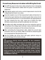
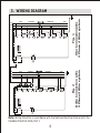
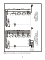
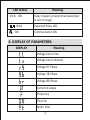
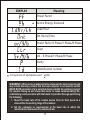
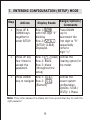
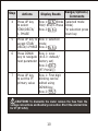
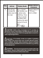
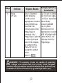
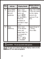
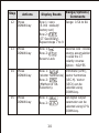
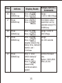
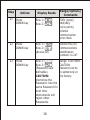
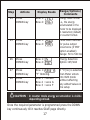
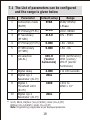
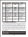
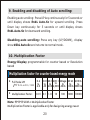
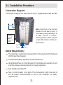
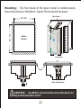
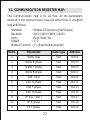
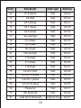
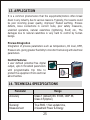
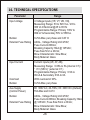
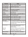
PROGRAMMING GUIDE LITTLE GENIUS PLUS [email protected] www.elmeasure.com Product & features at glance : This Manual is applicable for the Models: LG+AYXX A indicates display parameters & Y indicates nos of rows and may be replaced by any one digit number from 1 to 9. XX indicates software variants without any change in hardware construction and may be replaced by any two digit number from 00 to 99.Throughout this manual, the following methods are used to highlight important information: NOTE : Describes important considerations related to a device setup, feature or application. CAUTION : Alerts you to a condition which could potentially cause damage to the device or other external equipment. WARNING or DANGER: Warns you to avoid such conditions that could potentially cause serious personal injury and/or damage to equipment. Preventive Measures : Fuse: To avoid the possibility of short circuit, use a fuse that has a rating (current and type) that is specified. When replacing a fuse, turn OFF the power and unplug the power cord. Never short the fuse holder. Do Not Operate in an Explosive Atmosphere: Do not operate the instrument in the presence of flammable liquids or vapors. Operation in such environments pose a safety hazard. Do Not Remove Covers: The cover should be removed by ElMeasure's qualified personnel only. Opening the cover is dangerous, because some areas inside the instrument have high voltages. External Connection: Securely connect the protective grounding before connecting to the product under measurement or to an external control unit. If you come in contact with circuit, make sure to turn OFF the circuit and check that no voltage is present. Index 1. Features - 2 2. Unique Features - 2 3. Wiring Diagram - 4 4. Key Functions - 6 5. LED Indications - 6 6. Display of Parameters - 7 7. Entering Configuration (Setup) Mode - 9 8. Clearing Parameters - 19 9. Enabling and disabling of Auto scrolling - 20 10. Multifunction Factor - 20 11. Installation Procedure - 21 12. Communication Register Map - 23 13. Application - 25 14. Technical Specification - 26 PG/LGP/R06/0113 1 1. FEATURES l l l l l l l l l STAR (Wye)/ DELTA/1 Phase Programmable Universal Auxiliary (80 - 300 VAC / DC) supply PT ratio / CT ratio programmable including CT secondary True RMS measurement Active energy, positive energy accumulation & reverse Lock 'OLD' register to store the previously cleared energy value User configurable (Editable) password Simultaneous sampling of Volts & Amps Universal Voltage Input: 50 - 550 VAC (for UL 50-520 VAC) and Current Secondary (0.05A to 5A) with overload of 20% l Energy selection: Wh / VAh l Simultaneous sampling of Volts & Amps 2. UNIQUE FEATURES l 3/2 row, 6 digit displays on each row for better readability l Optional Programmable relay output maximum 2 (up to six threshold parameters) and tripping time up to 180 seconds-LGP5310 l Two sure selectable parameters from basic (VLL, VLN, A, Hz) or W, VA, or PF l Auto scrolling in both upward and downward direction l Auto-scaling of kilo, mega & giga decimal point l Energy display programmable-counter based or resolution based. Energy resetting at 999999KVAh*Multiplication factor l Optional RS232 communication with module 2 Precautionary Measures to be taken while Wiring the Circuit: Turn OFF the power to the circuit, when wiring the circuit. Connecting or removing measurement cables while the power is turned ON is dangerous. Take special caution not to wire a current measurement circuit to the voltage input terminal or vice-versa. Strip the insulation cover of the measurement cable so that when it is wired to the input terminal, the conductive parts (bare wires) do not protrude from the terminal. It is recommended to use appropriate pre lug after crimping the wire. Also, make sure to fasten the input terminal screws securely so that the cable does not come loose. Use cables with safety terminals that cover the conductive parts for connecting to the voltage input terminals. Using a terminal with bare conductive parts is dangerous if the terminal comes loose. After connecting the measurement cable, attach the current input protection cover for your safety. Make sure that the conductive parts are not exposed from the protection cover. Use the suitable star screw driver and apply optimum torque to prevent damage to the meter terminals. CAUTION : During normal operation of this instrument, hazardous voltages are present at the rear terminals, which can cause severe injury or death. These voltages are present throughout the potential transformer (PT), current transformer (CT) auxiliary supply, communication & Input / Output terminal. Installation, disconnection or removal of the meter should be carried out only by qualified, properly trained personnel, after de-energizing connected circuits. Improper installation, including improper wiring and/or improper grounding will void ElMeasure's warranty. 3 RS 485 S1 AR S2 S1 AY S2 S1 AB S2 VR VY LOAD RECEIVED N RS 485 S1 AR S2 S1 AY S2 S1 AB S2 VR VY VB N Fig. 1 Star Connection(3E) 3 Phase 4 Wire system A U X S2 S1 LOAD RECEIVED DELIVERED VB S2 S1 S2 S1 Fig. 2 Delta Connection (2E) 3 Phase 3 Wire system A U X S2 S1 DELIVERED LINE RY BN S2 S1 4 LINE R Y B N 3. WIRING DIAGRAM Note: Wiring should be in accordance with the National Electrical Code and/or the Canadian Electrical Code, Part I. Note: For DC Aux Voltage, +/- ve can be connected anyway. Common Relay 2 Common Relay 1 RS 485 COM 2 1 Fig. 4 Digital output Connection diagram S1 AR S2 S1 AY S2 S1 AB S2 VR VY VB S2 S1 RS 485 A U X Fig. 3 Single Phase Connection S1 AR S2 S1 AY S2 S1 AB S2 VR VY VB N R N LOAD RECEIVED DELIVERED N S2 S1 LOAD RECEIVED DELIVERED LINE RY BN S2 S1 S2 S1 5 LINE A U X COM 4. KEY FUNCTIONS In SET (Programming) mode Key In RUN (Measurement) mode UP/Right To select the value and accept the value (it act as a Right key in programming mode) Up scroll pages to look at different parameters DOWN To edit the value/ system To scroll pages to type down -ward in edit look at different mode and scroll through parameters the parameters 5. LED INDICATIONS: Meaning LED status KILO - ON Kilo MEGA - ON Mega KILO & MEGA - ON Giga KILO & MEGA - OFF Direct reading Minus (-) ON Lag/Minus Minus (-) OFF Lead/Plus Old - ON Old Readings (Cleared readings) 6 Meaning LED status I/O 1 - ON - Blink - ON Relay tripped (programmed parameter is out of range) Reserved Pulse LED Communication ON 6. DISPLAY OF PARAMETERS: Meaning DISPLAY Voltage line to line Voltage line to Neutral Voltage RY Phase Voltage YB Phase Voltage BR Phase Current Average Frequency Total VA Watts Total 7 Meaning DISPLAY Power Factor Active Energy Received Load Hour On Hours/Time Power Factor R Phase/Y Phase/B Phase Clear VA - R Phase/Y Phase/B Phase Parity Identification number Conversions of alphabets used (W) WARNING : When using a modem interface between the host computer and any remote device(s), ensure that the host computer is not used to set the BAUD RATE parameter of any selected device outside the working range of the modem. Doing so will cause that meter to cease communicating. Reestablishing communication with that meter is possible through performing the following: 1. Reset the baud rate of the remote device from its front panel to a value within the working range of the modem. 2. Set the computer to communicate at the baud rate at which the remote device has been set to communicate. 8 7. ENTERING CONFIGURATION (SETUP) MODE Step Range/Options/ Comments Actions Display Reads 1 Press UP & DOWN keys together to enter SETUP Row 1: with first digit “0” blinking Row 2: (SETUP, CLEAR) Displayed. 2 Press UP key four times to accept the password. Row 1: (Clear) Defines the Row 2: Blank clearing option for Row 3: blank the meter. (throughout the setup) 3 Press DOWN Row 1: key to navigate Row 2: (Element) Press DOWN key to decrement the first digit to “9” sequentially come to digit “.1” Defines the power system configuration. Options: STAR / DELTA/ 1 Phase Note: If any other password is already set move up and down key to reach the right password 9 Step Actions Display Reads 4 Press UP key to select STAR/DELTA/ 1. PHASE 5 Press UP key to Row 1: selected accept STAR/ mode DELTA/1.PHASE Row 2: 6 Press DOWN Row 1: xxxx key to navigate (415.0 -default/ next parameter factory set) Row 2: (PT Primary) 7 Press UP key to set the PT primary value Range/Options/ Comments Row 1: Blinks (selected mode StAr/ dELt/1.Phase blinks) Row 2: For selection press down key Row 1: First digit blinking can be edited using DOWN key. Row 2: CAUTION: To dismantle the meter remove the fuse from the voltage connections and Auxiliary connection. Short the external links for CT (S1 to S2). 10 Step Actions 8 Press UP key to accept the edited value for first digit. Display Reads Range/Options/ Comments Row 1: Second Program Range for digit blinking, can PT Primary : be edited using 100V to 999kV DOWN key. Press UP key to accept the edited value. Continue the same method till fourth digit. Row 2: CAUTION : Before wiring, de-energize the PT secondary by opening the circuit or removing the secondary fuse. Do not short the PT secondary. All wiring must confirm to any applicable local electrical codes/ engineering practices. CAUTION : CT secondary circuits are capable of generating lethal voltages and currents when open circuited with their primary circuit energized. Standard safety precautions should be followed while performing any installation or service on the device (e.g. shorting CT secondaries, etc.) CAUTION : Do not connect ground to the shield at both ends of a segment. Doing so allows ground loop currents to flow in the shield, inducing noise in the communication cable. 11 Step 9 Actions Press UP key Display Reads Row 1: Decimal point blinking. Can be set at appropriate location using DOWN key. Ascertain the correct scale (Kilo/ Mega/Giga) is selected. Kilo/ Mega/Giga is placed on the right hand side of the display by Letter K/M/G. Press UP key to accept the edited value. Row 2 : Range/Options/ Comments Eg: To set 11.00kV Set first four digits (1100)as explained above keep pressing DOWN key to place decimal point at appropriate location USE UP/DOWN KEY Letter K/M/G will indicate the Kilo/ Mega/Giga. DANGER : PT secondary circuits are capable of generating lethal voltages and currents with their primary circuit energized. Standard safety precautions should be followed while performing any installation or service on the device (e.g. removing PT fuses, etc.) 12 Step Actions Display Reads Range/Options/ Comments 10 Press DOWN key to go to the next parameter. Row 1: xxxx (415.0 -default/ factory set) Row 2: (PT Secondary). Follow the procedure as described in steps 7 to 9. Range: 50V to 550V If value set is above the limit, display returns to the maximum PT sec value. 11 Press DOWN key Row 1: xxxx (5.000-default/ factory set) Repeat steps 7 to 9 to change the settings. Row 2 : (CT Primary) Program Range for CT Primary 0.5A to 99kA CAUTION : PTs are required for delta systems NOTE: If value set is above this limit, display returns to the maximum PT sec value acceptable. 13 Step Actions Display Reads Range/Options/ Comments 12 Press DOWN key Row 1: xxxx Range: 0.5A to 6A (5.000 -default/ factory set) Row 2: (CT Secondary). Repeat steps 7 to 9 13 Press DOWN key Row 1: Row 2: Revers Lock Reverse lock - blocks energy accumulation in case the CT polarity reverse Option : NO/YES 14 Press DOWN key Row 1: (Vector harmonics) Row 2: (Method of VA Selection). Arithmetic (Arth), Vector harmonics (UEC.H). Vector (UECt) can be selected using DOWN key. 15 Press DOWN key Row 1: 1st digital output parameter can be selected using UP & DOWN key. Row 2: 14 Step Actions Display Reads Range/Options/ Comments 16 Press DOWN key Row 1: Row 2: Range : 0.000 to 999.9 Mega 17 Press DOWN key Row 1: Row 2: 2nd digital output parameter can be selected using UP & DOWN key. 18 Press DOWN key Row 1: Row 2: Range :0.000 to 999.9 Mega 19 Press DOWN key Row 1: Range: Row 2: 1to 180 seconds (digital output trip delay time, default/ factory set : 3.000sec 20 Press DOWN key Row 1: xxxx (9600 default/ factory set) Row 2: (baud rate) communication speed. 15 Defines the baud rate. Option :2400,4800, 9600,19.20k Step Actions Display Reads Range/Options/ Comments 21 Press DOWN key Row 1: Row 2: EUEn (even)/ odd(odd)/ no(no parity) Internal communication error check 22 Press DOWN key Row 1: Row 2: (device ID) Defines the (ID) communications identification number.1 to 247 23 Press DOWN key Row 1: Row 2: (Password user definable). CAUTION: memorize the Password. Use the same Password for next time. Instruments will reject other Passwords. Range: 1000-9999. CAUTION: Password can be re-setted only at the factory. 16 Step Actions Display Reads Range/Options/ Comments 24 Press DOWN key Row 1: Row 2: Energy value format i.e., the energy accumulated in the meter to be displayed in resolution (default) or counter format. 25 Press DOWN key Row 1: Row 2: Pulse width defined for pulse output occurrence (if POP option enabled) Range: 50 to 500 ms 26 Press DOWN key Row 1: Row 2: Energy Selection Option: Wh/VAh 27 Press DOWN key Row 1: "Y" blinking. 28 Press DOWN key Row 1 : xxxxLL Row 2 : xxxx A Row 3 : xxxx F If “n”(no) is selected then Meter enters into RUN mode without affecting any edited Values in the setup CAUTION : In counter mode energy accumulation is visible depending on load. Once the required parameter is programmed press the DOWN key continuously till it reaches SAVE page directly. 17 7.1 The List of parameters can be configured and the range is given below Sl.No. Parameter Default setup 1 Connection mode (ELEM) STAR STAR/ DELTA/ 1.Phase 2 PT Primary(PT.Prı) 415.0 100V- 999kV 3 PT Secondary (PT SEC) 415.0 50V - 550V 4 CT Primary(CT.Prı) 5.000 0.5A - 99kA 5 CT SECondary (CT SEC) 5.000 0.5A - 6A 6 VA selection (UA.SL) UEC.H (Vector harmonics) 7 Digital delay 3.000 1 to 180 seconds 8 Digital o/p 1 Parameter (d1.Pr) Digital 1 Threshold Limit (d1.Hi) dSbL * 1000 0.001 to 9999 × 106 dSbL * 9 10 Digital o/p 2 Parameter (d1.Pr) Range Arith (Arithmetic)/ UECt (vector)/ UEC.H (Vector Harmonics) * S1.Ph, REV.A, DG[Over (VLL,A,F,W,Wh); Under (VLL,A,F,PF) EB[Over (VLL,A,F,W,Wh); Under (VLL,A,F,PF) Note: Programming is applicable as per displayed parameter. 18 Sl.No. Parameter Default setup 11 1000 0.001 to 6 9999 × 10 12 Digital 2 Threshold Limit (d1.Hi) Baud rate (bAUd) Range 9600 2400 to 19.2k 13 Parity (Prty) Even Even/ Odd/ no 14 Device Id (dEV.Id) 1.000 1.000 to 247.0 15 Reverse lock(rEU.L) 16 Password (PWd) 1000 1000 to 9999 17 EnEr (Energy) rESL rESL /COUΠ 18 POP ON time (POP.t) 250.0 50 to 500 milliseconds 19 Energy Selection (E.SEL) no Wh Yes/no Wh / VAh 8. CLEARING PARAMETERS: To Clear parameters of the Little Genius Plus series from the front panel, Press UP and DOWN Keys together, and 'Set.CLr' (Set-Clear) is shown on the display. Enter the Password (default password is 1000. Set up and clear has the same password) and it will display “CLr”. Press UP Key for selecting (Integ Clear). Display will prompt to select 'y' or 'n'. Press DOWN key for changing 'y' or 'n' and Press the UP key to do the operation. CAUTIONS : Once the data is cleared (except energy) the value will not be retained. 19 9. Enabling and disabling of Auto scrolling: Enabling auto scrolling: Press UP key continuously for 5 seconds or until display shows EnbL Auto.Sc for upward scrolling. Press Down key continuously for 5 seconds or until display shows EnbL Auto.Sc for downward scrolling. Disabling auto scrolling: Press any key (UP/DOWN), display show dSbL Auto.Sc and returns to normal mode. 10. Multiplication Factor Energy Display programmable for counter based or Resolution based Multiplication factor for counter based energy mode l Full Scale kW 3 V Pri LL x A Pri / 1000 l Multiplication Factor: 0.4 to 4.0 4.01 40.1 400.1 4Mega 40 M 400 M to to to to to to 40 400 4,000 40 M 400 M 4000 M 0.01 0.1 1.0 10 100 1000 10000 Note: 999999 kVAh × Multiplication Factor Multiplication Factor is applicable only for designing energy reset. 20 11. Installation Procedure Connection Diagram: Connection Diagram for Little Genius Plus / Digital Output and RS 485 RS485 Note : Connections to the terminals located at the rear side of the unit is to be made by using preferably 12 to 2 2 14 SWG (2.6mm to 2.6mm ) industrial grade wire. Relay rating No contact SPST. 250VAC / 30VDC @ 2 Amps resistive. Connection from AMF panel to Changeover EB/DG Relay 1 Common Common Relay 2 Safety Requirments: The warnings, cautions & notes specified in this guide shall be followed strictly (see the all pages). The specified safety regulations must be observed. Use dedicated fuse or circuit breaker in the Voltage and auxiliary circuit in all the elmeasure make meters for the safe operation. Fuse shall be used after PT. Fuse / circuit breaker is not part of the instruments (refer rare side of the TB Label). Recommended to use by the customer for safety requirements. 21 Mounting : The front bezel of the basic model is molded plastic. Bezel dimensions is 96x96mm. Depth 55mm behind the bezel. Side Clamp VR VY VB AB Panel Cutout AR AY 92 mm N 92 mm Side Clamp Panel After Installation CAUTION : Use MCB to connect and disconnect the device for auxiliary and measurement circuit. 22 12. COMMUNICATION REGISTER MAP: This Communication map is for LG Plus. All the parameters declared in the communication map are either float or unsigned long and follows; Standard Baudrate Parity Stopbit Modbus Function : : : : : Modbus RTU protocol (Half Duplex) 2400 / 4800 / 9600 / 19200 Even / Odd / No 1/2 03 (Read holding register) Sl.No. Parameter Data type 1 Watts Total float 40101 2 Watts R phase float 40103 3 Watts Y phase float 40105 4 Watts B phase float 40107 5 VAR Total float 40109 6 VAR R phase float 40111 7 VAR Y phase float 40113 8 VAR B phase float 40115 9 PF Ave. (Inst.) float 40117 10 PF R phase float 40119 11 PF Y phase float 40121 23 Address Sl.No. Parameter Data type Address 12 PF B phase float 40123 13 VA total float 40125 14 VA R phase float 40127 15 VA Y phase float 40129 16 VA B phase float 40131 17 VLL average float 40133 18 Vry phase float 40135 19 Vyb phase float 40137 20 Vbr phase float 40139 21 VLN average float 40141 22 V R phase float 40143 23 V Y phase float 40145 24 V B phase float 40147 25 Current Total float 40149 26 Current R phase float 40151 27 Current Y phase float 40153 28 Current B phase float 40155 29 Frequency float 40157 30 Wh Received float 40159 31 Load Hours Received Unsigned long 40217 24 13. APPLICATION It is a common phenomenon that the equipments/motors often break down in any industry due to various reasons. Typically, the reasons could be poor incoming power quality, improper/ floated earthing, Process defects, loose connections in current route, poor safety measures, unskilled operators, natural calamities (lightening, flood) etc., The damages due to natural calamities is very hard to control by human beings. Process Integration Integration of process parameters such as temperature, Oil level, RPM, Pressure etc. giving greater flexibility to monitor them along with electrical parameters. Control Features 2 user defined potential free digital output, upto 6 threshold parameters with programmable trip time to protect the equipment from electrical abnormalities. 14. TECHNICAL SPECIFICATIONS Range Parameter Accuracy Class 1 (Default) IEC 61036, CBIP 88, Class 0.5(Option) Sensing/ Measurement True RMS, 1 Sec update time, 2 Quadrant Power & Energy 25 14. TECHNICAL SPECIFICATIONS Range Parameter Input voltage 4 Voltage inputs (VR, VY, VB, VN), Measuring Range: 50 to 520 VLL / 28 to 300 VLN Nominal @45 to 65 Hz Programmable Range: Primary 100V to 999 kV & Secondary 50V to 550VLL Burden External Fuse Rating 0.2VA Max. per phase and CAT lll AXIAL, Voltage Rating VAC:250V; Fuse Current:200mA; Breaking Capacity:10kA @ 125VAC; Fuse Size:5mm x 20mm; Blow Characteristic: Slow Blow; Body Material: Glass Input Current Overload Burden Current inputs (AR, AY, AB), Measuring Range: 0.05A to 5A (internal CT) / “ <1V (SELV)” (external CT ) Programmable Range: Primary 0.5A to 99 kA & Secondary 0.5A to 6A With overload of 20%. 0.2VA Max. per phase Aux-Supply (Control Power) 80 300V AC, 40-70Hz, 80 300V DC (Default) 5VA Max and CAT ll Burden AXIAL, Voltage Rating VAC:250V; Fuse Current:200mA; Breaking Capacity:10kA @ 125VAC; Fuse Size:5mm x 20mm; Blow Characteristic: Slow Blow; Body Material: Glass External Fuse Rating 26 Range Parameter Display Resolution 2/3 Row, 6 digits (10mm height) CT PT Ratio Max 2000 MVA Programmable Protection Class 3 Humidity 5% to 95% non condensing Pollution Degree 2 (As per IEC 61010) Altitude Below 2000 mts Insulation Double Insulation Ingress Protection IP 51 As per IEC 60529 ( As per IEC 61010-1) Operating Temperature -10OC to + 55OC (14OF - 131OF) Storage Temperature O O O O -25 C to +70 C (-13 F - 158 F) Measurement Category CAT lll ( As per IEC 61010) Wire Gauge (connecting wires) 12-14 swg (2.6 to 2.0mm2) Factory wiring only. 2.5mm2 crimp terminals (U cut Lugs) with max strip length of 4mm. Insulated or Bare shall be used Torque 1N-m Communication RS 485 serial channel connection Industry standard Modbus RTU protocol (RS232 optional) 2400 bps to 19200 bps (preferred 9600 bps) 2000 volts AC isolation for 1 minute between communication and other circuits. Baud rate Isolation Dimension Bezel 96 x 96 mm - Depth 55mm behind bezel Panel Cutout 90 -0 +2 +2 X 90 -0 mm 27 TROUBLESHOOTING Due to programming error, site conditions, some problems can cause the Meter malfunction. The fault symptoms and their remedial action for correction is given below. 1. If the display does not turn ON: a) Check that there is at least 80 volts available to the power supply (L and N connections) on the Aux supply terminals. If the above steps do not solve the problem, Contact ElMeasure or your local ElMeasure representative and report the problem and results of the test. 2. a) b) c) If the voltage or current readings are incorrect: Check that the Connection mode (star/delta) is properly programmed. Check that the voltage and current ratios are properly set. Check the output of the CT's and PT's being used. 3. If the kW or Power Factor readings are incorrect but voltage and current readings are correct: a) Make sure that the phase relationship between voltage and current inputs are correct by comparing the wiring with the appropriate wiring diagram. b) CT reversal can be observed by either seeing the phase wise kW. Negative kW is shown where the current polarity is reversed, need to be corrected. Model where kW information is not available, you may check Amps Phase angle. 4. a) b) c) d) If RS-485 communication does not work: Check that the baud rate of the host computer/PLC is the same as Meter. Check that the device ID of the meter are unique and should not replicate. Check all communications wiring is complete. Check that the number of data bits is set to 8, with one stop bit and even parity. If the symptom persists after performing the specified steps, or if the symptom is not listed above, contact your local ElMeasure representative or the technical support / customer support department. 28 WARRANTY AND REGISTRATION Every product of ElMeasure is warranted for 18 months from the date of invoice for the defects in materials and workmanship when products are used in normal specified conditions. The warranty is void to the product which has been damaged due to improper installation, improper handling, improper connections, neglect, misuse, accident, and abnormal conditions of operation and natural calamities or acts of god. Any attempt of dismantling and unauthorized repair or modifications shall also render the warranty null & void. 1. Failure of products during warranty In India Customer shall report the failure to the nearest ElMeasure contact point or dealer at the earliest once noticed. ElMeasure shall replace the product failed due to workmanship or defects in materials against receipt of failed product. Burnt, blown, damaged products are not covered under warranty and hence no replacements shall be given. In the event of product un-available for replacement at ElMeasure or dealer, same shall be arranged at the earliest. Replacement of product is solely at the discretion of dealer or the ElMeasure representative who receive the failed product. ElMeasure SE may on a case to case basis, recommend for the advance replacement of product mentioning the reasons and justifications for doing so. Sales Manager shall approve advance replacement in genuine cases. The defective product shall be collected and sent to ElMeasure factory within 30 calendar days. Non compliance shall result in debiting cost of the product to the Customer. Burnt, abused, damaged products shall be forwarded to ElMeasure's Service Center at Bangalore for investigation, transportation pre-paid. Upon investigation, If found the rectification is possible, an estimation for servicing is sent to the customer. Rectification shall be done on receipt of approval for the charges with advance payment only. 2. Failure of products outside warranty In India The defective products shall be forwarded to ElMeasure Service Center at Bangalore for rectification, transportation pre-paid. Upon investigation, estimation for servicing is sent to the customer. Rectification shall be done on receipt of approval for the charges with advance payment only. ElMeasure, as a policy, do not provide replacement for the products outside warranty. For Distributor / Dealer's use only Seal Invoice No.: Date: Elecon Measurements A group of ElMeasure India Private Limited HO & Unit-I 764, 4th Phase, 707, Yelahanka New Town, Bangalore - 560 064. INDIA T : +91 80 2846 1777/744 F : +91 80 41272461 CS : +91 80 3290 4489 E : [email protected] Unit-II: Goutham Garden, No. 4, Veerapandi, Coimbatore - 641019 INDIA T : 0422 2697200. TF : 0422 2695200 E : [email protected] Unit-III Plot No.: 323/19, Camp Road, Selaqi, Dehradun, UTTARANCHAL C : 097600 02492, 12492 E : [email protected] Unit-IV 1049, MIG 3rd Phase, Yelahanka New Town, Bangalore - 560 064. INDIA Sales Offices: BANGALORE | CHENNAI | COIMBATORE | MUMBAI | DELHI | HYDERABAD | USA | UAE www.elmeasure.com


![[1 ] StorageTek SL8500](http://vs1.manualzilla.com/store/data/005684950_1-d7f31af8d49e38e9e4476c8a63e026d0-150x150.png)