1
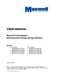
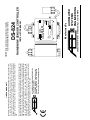
Visit us on the Internet at: www.goase.com
AUTOMATED SYSTEMS ENGINEERING, INC.
2519 E SAINT VRAIN ST
COLORADO SPRINGS, COLORADO 80909
PHONE: 719-599-7477 FAX: 719-599-7482
The customer shall be responsible for all costs incurred in the removal or reinstallation and shipping of the
product for repairs. Within the limitations of this warranty, inoperative units should be returned, freight
prepaid, to ASE, and we will repair or replace, at our option, at no charge to you with return freight paid by
ASE. It is agreed that such repair or replacement is the exclusive remedy available from ASE and that
ASE IS NOT RESPONSIBLE FOR DAMAGES OF ANY KIND, INCLUDING INCIDENTAL AND
CONSEQUENTIAL DAMAGE. Some states do not allow the exclusion or limitation of incidental or
consequential damages so the above exclusion may not apply to you. The warranty gives you specific
legal rights, and you may also have other rights which vary from state to state.
The DS-824 is warranted against defects in workmanship and materials for two years from date of sale.
This warranty does not apply to damage resulting from accident, misuse, or alteration nor where
connected voltage is more than 10% above the configured operating voltage, nor to equipment improperly
installed or wired or maintained in violation of this Owner’s Manual. No other written or oral warranty
applies. No employee, agent, dealer or other person is authorized to give any warranties on behalf of
ASE.
LIMITED WARRANTY
&5Ä
%10641.59+6%*
/#07#.10
#761/#6+%
56#0&$;4'5'6
2519 East Saint Vrain St Colorado Springs, Colorado 80909
AUTOMATED
SYSTEMS
ENGINEERING
Manufactured By
016(14*+)*81.6#)'%10641.
%#76+10
%10641.
#8#%#8&%
+0276
Ä8#%&%O#*\
1(( 10 64+2
+0&+%#614
4#+050195'0514%10641..'4
ENCLOSURE TYPE 3R
#761/#6'&
5;56'/5
'0)+0''4+0)
INSTALLATION MANUAL
RAIN/SNOW SENSOR CONTROLLER
DS-824
CAUTION: Read all instructions carefully before installation.
Save this Installation Manual for future reference.
General Safety Instructions
2
The rubber “boot” protruding from the bottom of the DS-824 enclosure is the temperature sensor. For
proper temperature detection the DS-824 must be mounted outdoors, away from furnace vents, dryer
vents, and other sources of heat. Note that, when powered, the DS-824 precipitation grid will always
remain hot. This is normal. This allows the grid to continuously melt snow and evaporate both rain and
snow from the grid.
Selecting a Mounting Location for the DS-824 Enclosure
1" CONDUIT
The sensor cable comes preinstalled but may be shortened as
CLAMP
needed. Strip the outer insulation and shield from the cable and
terminate each conductor following the color code printed on
the circuit board. The bare drain wire should be installed into
the terminal marked “Shield”. Wrap a cable tie securely around
the cable in the enclosure to provide additional strain relief
between the flexible enclosure gland and the free end of the
cable. Please call for guidance if additional length is required. Erratic operation may result if the proper
cable is not used.
The remote DS-824 precipitation/moisture sensor may be
mounted in a number of ways depending on the application.
The unit operates at a safe 24 VAC/VDC and can withstand
DRIP EDGE
immersion in water. For roof and gutter deicing applications
the sensor head may be mounted in the gutter against the
SENSOR
fascia board with a 1” “C”-style conduit clamp. Allow part of
the sensor grid to be exposed to snowfall. This allows the
sensor to initially trigger when snow starts falling and remain
triggered as long as the roof/gutter heater continues to drip
GUTTER
melted snow from the roof edge when temperatures are below
freezing. The sensor may also be installed inside and near the
top of the downspout using a 1” conduit hanger and mounting
plate. As water is
DOWNSPOUT
melted in the gutter
it will run to the
downspout, hitting and retriggering the sensor. We do not
recommend laying the sensor in the gutter. Constant immersion
SENSOR
will corrode the grid and the sensor may miss a windblown
MOUNTING
snow trigger.
PLATE
Moisture Sensor Mounting & Termination
4. Replace fuse F1 with a 2 Amp 32 V or 250 V 3AG fast acting fuse ONLY.
2. To avoid shock hazard do not open the front cover with power connected to the DS-824 or
any controlled equipment.
3. Limit input voltage to 22-28 VAC/VDC.
1. THIS UNIT SHOULD BE INSTALLED, OPENED, AND REPAIRED BY QUALIFIED
PERSONNEL ONLY!
Power & Activation Indicator
7
Compatible with the DS-824
Simple Installation & Operation at a Competitive Price
Visit www.goase.com for more information
Need Indoor Monitoring & Control?
Take a Look at the ASE CDP-2
It is always a good idea to test the operation of the DS-824 prior to the winter season. Procure some
clean water and, if the outdoor temperature is above the trigger point, a can of spray component cooler
(Radio Shack Part #64-4321 or equivalent.) Clean the precipitation grid following the procedure outlined
above and allow it to dry. Apply power to the DS-824 and drip some of the water onto the precipitation
grid, and then spray the temperature sensor protruding from the base of the enclosure with the component
cooler. Once the temperature sensor has reached the trigger point with water still present on the grid the
DS-824 will activate. The user should hear the internal control relay close. Proper operation has been
confirmed. Allow the grid to dry completely. To clear the Delay-Off timer place the override switch into
“Standby/Reset”, and then back to the “Automatic” position.
Preseason Snow Detection Testing
A yellow lamp is mounted on the base of the DS-824 to indicate operational status. If this lamp is OFF the
DS-824 is not receiving power. If this lamp is steady ON the DS-824 is powered but not triggered. If this
lamp is FLASHING the DS-824 is both powered on and has activated the deicing system. Note that, even
though snow may have stopped, the DS-824 indicator may be flashing indicating the system is on. The
indicator will continue to flash during the Delay-Off drying cycle.
Color
Green
Black
Orange
Red
White
Function
Standby/Reset
Manual On
Deice On Mon
Deice On Mon
Return
6
It is recommended that the DS-824 be powered down and the grid wiped clean with clear water at least
once every 4 months. Heavy deposits may be removed using a non-metallic scouring pad (Scotch-BriteTM
or equivalent.) However, after a number of years, the corrosive elements left behind when water is
evaporated out of the precipitation grid will eventually damage the grid rings. The precipitation grid can be
easily replaced by ordering and installing a new MG-3 “Moisture Grid Assembly”. Reference the
“Moisture Sensor Mounting & Termination” section for information on replacing the precipitation grid.
Precipitation Grid Maintenance & Replacement
activation of the sensor.
Pin
1
2
3
4
5
An external control/monitor jack is provided on the DS-824. Order
the optional CS-1 control/monitor cable to access this feature.
Connecting Black to White will activate the “Manual On” function.
Connecting Green to White will activate the “Standby/Reset”
function. The Red/Orange leads are connected to an internal low
power monitor relay. This relay, rated at 24 VAC/VDC at 400 ma,
will close with the load relay and can be used to externally monitor
External Control/Monitor Operation
If the override switch is placed in “Manual On” for less than 2 seconds, then switched back to
“Automatic” the controller will execute one delay off cycle. This can be used to clear a frost or hail
buildup without the danger of leaving the system in a continuous “Manual On” condition. “Standby/Reset”
can still be used to clear this delay off cycle.
An override switch mounted on the side is provided for testing and special operational requirements.
Placing the switch in the “Automatic” position will allow the sensor to operate normally, activating the
controlled equipment as needed. Placing the switch in “Manual On” will close the load relay, activating the
controlled equipment. The “Standby/Reset” position prohibits triggering of the unit, clears any active delay
timer, and opens the load relay. In order to reduce excessive runtime for the heater the “Manual On”
mode will remain in effect for a maximum of 40 hours, then return to “Automatic” mode even if the
switch is still in the “Manual On” position. You may put the DS-824 back into “Manual On” mode by
switching to “Automatic”, then back to “Manual On”. This will restart the 40 hour timer.
Manual Override Switch Operation
The DS-824 is shipped with the TEMP and DEL adjustments in the center position, representing 39°F
(3.9°C) and 30 minutes of Delay-Off time respectively. The Sensitivity control is set for highest sensitivity.
Depending on local conditions the user may find that fine adjustment of the controls may provide more
satisfactory operation. If the sensor does not trigger during very wet snows the trigger temperature may
need to be adjusted higher. Conversely, if the user notices false triggers during cold rains that do not
freeze, the trigger temperature may need to be lowered. Locations susceptible to blowing ground snow or
snow falling from eaves or trees may benefit from a lower sensitivity adjustment. The Delay-Off time can
also be adjusted or the range expanded using the LD configuration switch to provide clean melt-off without
excessive running time. Fine adjustment can both save operating expense and provide more reliable
operation. However, to keep reliability high, always make adjustments in small increments.
ALWAYS USE CARE WHEN REPLACING THE ENCLOSURE FRONT COVER!
Be sure the front cover gasket is not pinched or rolled. Do not overtighten the front cover screws.
Fine Adjustment for Efficient Operation
Load
Switch Jack
LED Jack
Control/Monitor Jack
Configuration Switch
Grid Jack
The DEL configuration switch activates the “Delay Off” drying
cycle timer on the DS-824. The timer allows the DS-824 to dry
the heated surface through evaporation once precipitation has
stopped. The drying cycle reduces the chance of moisture left
behind refreezing into ice. The Long Delay (LD) configuration
switch determines the time span of the drying cycle. LD off sets a 30-90 minute span. LD on sets a 2-6
hour span. This timer is restarted by each precipitation detection. Therefore, the DS-824 will continue to
operate as long as precipitation is detected, then for the Delay Off period once precipitation has stopped.
All "sensor" modes (DEL off) provide a 2 minute closure to reduce cycling of an external controller. When
3
The following table outlines the operating modes for the DS-824 and explains
the functions of the adjustments. Trigger temp (TT) is adjustable from 34qF44qF using the “Temp Adjust” control. When ambient air temperature (AT) is
below this trigger point precipitation is assumed to be snow. When above this
temperature, precipitation is assumed to be rain. The SNOW switch will cause
the sensor to activate when snow is detected. The RAIN switch will cause the
sensor to activate when rain is detected.
Setting the Configuration Switches and Adjustments
Delay Adjust
Temp Adjust
Probe Jack
Sensitivity Adjust
Input Power
Be sure the front cover gasket is not pinched or rolled. Do not overtighten the front cover screws.
ALWAYS USE CARE WHEN REPLACING THE ENCLOSURE FRONT COVER!
This can allow water into the enclosure causing a potential shock or fire hazard. It is recommended that a
weatherproof condulet or junction box be mounted below the DS-824 for termination of the power and load
pigtails to the building wiring.
DO NOT DRILL HOLES THROUGH THE ENCLOSURE FOR MOUNTING!
The DS-824 can be mounted by screwing the base conduit hub onto an appropriate size free-standing
conduit or by using the mounting holes in each corner of the enclosure.
TT>AT>15qF
Snow sensor w\LTC
30-90 Min
2 Min
2 Min
LD Off
Not Used
Not Used
AT>TT
AT>TT
Precipitation controller
Rain sensor
Rain controller
4
30-90 Min
2 Min
30-90 Min
2 Min
TT>AT>15qF 30-90 Min
Precipitation sensor
Snow controller w\LTC
TT>AT
TT>AT
Snow controller w\o LTC
Trigger
Function
Snow sensor w\o LTC
2-6 Hr
2 Min
2-6 Hr
2 Min
2-6 Hr
2-6 Hr
2 Min
2 Min
LD On
X
X
X
X
ON
OFF
ON
OFF
LTC
ON
OFF
ON
OFF
ON
ON
OFF
OFF
DEL
ON
ON
ON
ON
OFF
OFF
OFF
OFF
RAIN
Recommended Switch Settings by Function
OFF
OFF
ON
ON
ON
ON
ON
ON
SNOW
POWER MUST BE CYCLED FOR CONFIGURATION SWITCH CHANGES TO TAKE EFFECT
The DS-824 precipitation sensor can detect even a single snow flake or rain
drop. However, if the DS-824 is mounted in an area susceptible to high
winds, dripping condensation, or blowing ground snow, nuisance triggering of
the sensor may occur. While proper placement is the best remedy, the
Sensitivity control can also be used to reduce nuisance triggering. An internal
timer checks the precipitation sensor for moisture once per second and keeps
a running count of the number of continuous seconds the grid is triggered. The highest sensitivity setting
(toward More) requires 3 seconds of continuous precipitation detection before the unit triggers. The
lowest sensitivity setting (toward Less) requires a full 4 minutes of detection before the unit triggers. If a
trace amount of snow blows onto the grid from a drift or overhang it will likely be melted and evaporated
within 1-2 minutes. Similarly, a very light snowfall may also clear quickly from the grid. If these conditions
should be ignored by the sensor the Sensitivity control can be adjusted as required. However, to prevent
non-triggering during a true event, it is recommended that the user start at highest sensitivity (More),
then adjust while monitoring operation over time.
The Low Temperature Cutoff (LTC) option is typically used on snow melting
systems with limited output capacity. If selected, the sensor will not trigger
if precipitation is initially detected below 15qF. However, if the deicing
system has been activated, precipitation continues, and the ambient
temperature drops below 15qF, LTC will be ignored. This assures that
water on the surface from melting snow will not immediately refreeze into
ice as a result of deactivating the deicing system.
in "controller" mode (DEL on) the Delay Off time can be adjusted from 30-90 minutes (LD Off) or 2-6 hours
(LD On) using the “Delay Adjust” control. Note the “Forced Manual On” function at the low end of the
Delay Adjust control. The relay will close when this area is entered and open when exited. Only use the
“Forced Manual On” function for testing. Never leave the Delay Adjust control near the “Forced Manual
On” area during normal operation.
Typical Wiring
4'6740
59+6%*'&8
.1#&
;'..19
;'..19
.1#&
;'..19
;'..19
5
24VAC/VDC Sensor Supply, Dry Contact Thermostat-Style Control
8#%8&%5722.;
+0#
+0$
&5Ä
24VAC/VDC Sensor Supply, Supply Voltage Out
8#%8&%5722.;
+0#
+0$
&5Ä
The two load leads of the DS-824 do not supply power directly to your load. The relay inside the
DS-824, like a switch or thermostat, is used to switch a voltage of your choice. While not as convenient
as directly supplying power for the load this allows you to operate the DS-824 from one voltage while
controlling a load of a different voltage without adding an external relay or contactor. For example, the
DS-824 can be powered from 24VAC but can directly control a 12VDC signal for a contactor coil or can
operate from 24VAC and provide a dry contact thermostat-style closure for a boiler. The following
diagrams show some possible wiring schemes for connecting the DS-824 to your load. For clarity the
GROUND lead is not shown.
The sensor supply voltage can be in the range of 22-28 VAC/VDC. The supply input leads (IN A
and IN B) are not polarity sensitive and can be connected to either polarity of a DC supply. A
standard 24VAC 20VA HVAC-type transformer will supply enough power for the DS-824 and an optional
CDP-2 indoor control/display panel.