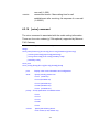
1
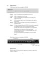
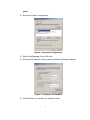
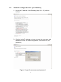
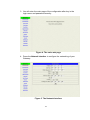
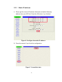
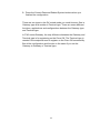
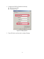
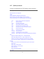
User’s Manual IP Telephony Gateway Model No.: SP5050 / SP5052 / SP5054 http://www.micronet.info Version 2.0 Table of Contents 1. 2. 3. 4. INTRODUCTION ......................................................................................2 1.1 Features and specification .............................................................2 1.2 Accessories and equipment ...........................................................3 1.3 Appearance ......................................................................................4 SETTING UP THE TCP/IP PROTOCOL...................................................6 2.1 System Requirements .....................................................................6 2.2 IP Environment Setting ...................................................................6 2.3 Network configurations in your Gateway ......................................9 MAKING A VOIP CALL..........................................................................14 3.1 Configure the Gateway in the Peer-to-Peer mode ......................14 3.2 Configure the Gateway into the GK routed mode.......................17 COMMAND LIST....................................................................................19 4.1 Hyper Terminal Setting..................................................................19 4.2 Command List................................................................................22 1 1. Introduction Micronet SP5050 series VoIP FXO Gateway provides voice/fax service over IP network with H.323 v3 protocol. By connecting to your existing ADSL or cable modem service, which allows the use of a single, network for voice and fax services with consequent saving in network infrastructure and greatly reduced telephone charges. Ideal solution for providing low cost communications between headquarters and branch offices in the world, as well as for SOHO and office telephony applications. Micronet SP5050 series Gateway provides FXO interface to connect PSTN analog lines, and converts voice/fax signal onto IP network. You can manage it via RS-232 console, TELNET, and web browser. 1.1 Features and specification Interface y One 10Base-T RJ-45 LAN port y One asynchronous console with RS-232C DB-9 connector y 2 FXO RJ-11 ports for SP5052 y 4 FXO RJ-11 ports for SP5054 y 6 FXO RJ-11 ports for SP5050 y AC power outlet y AC power switch General Features y Compliant with ITU-T H.323 v4 y Automatically Gatekeeper Discovery y Support peer-to-peer mode without Gatekeeper y Support auto-attendant (2nddial Tone / Voice greeting) y PSTN Polarity Reversal Detection y Line hunting y E.164 (Telephone Number Plan) y DTMF dialing y DTMF detection/generation 2 y y y y y y Support static IP and DHCP Provide QoS function by ToS (Type Of Service) setting Provide T.38/FAX and voice Auto-Switching Microsoft NetMeeting v3.0 compatible TFTP/FTP software upgrade Remote configuration/reset via Telnet and web browser Audio Features y Codec -- G.711 a/μ-law, G.723.1 (6.3K/bps), G.729A (Optional) y VAD (Voice Activity Detection), CNG (Comfort Noise Generate) y G.168/165-compliant adaptive echo cancellation y Dynamic Jitter Buffer y Bad Frame Interpolation y Call Transfer (H.450.2) y y y y Call Forward (H.450.3) Call Hold (H.450.4) Gain Settings Provide Call Progress Tone: dial tone, busy tone, call-holding tone and ring-back tone Management Features Three easy ways for system configuration y Console port: RS-232C port y TELNET y HTTP Brower (e.g. Internet Explorer) 1.2 Accessories and equipment y y y y y The voice gateway The AC power cord The user guide The manual CD The console cable in RS-232 interface 3 1.3 Appearance Front Panel: Here is an example for SP5050. Power: L1-L6: Link: Light on means Micronet SP5050 is power on. Light on means the line is in use. Light on means Micronet SP5050 is connected to the network correctly. Act: LED should be light on and in flash display when data is transmitting. Ready: Light on and in slow flash means Micronet SP5050 is in operation mode. Status: 1. Light on means Micronet SP5050 successfully registered to Gatekeeper when it is set as Gatekeeper Mode. 2. LED flash means Micronet SP5050 is not registered to Gatekeeper when it is set as Gatekeeper Mode. 3. When Micronet SP5050 is in downloading mode, LED should be flash as well. 4. Light off means Micronet SP5050 is in Peer-to-Peer Mode. Back Panel: Here is an example for SP5050. Ethernet Port Ethernet port is for connecting the gateway to network, supporting Ethernet 10Base-T. 4 The pin-out is as following: PIN 1, 2: Transmit PIN 3, 6: Receive COM: RS232 console port (DB-9 male connector) Note: use straightforward cable to connect to your computer. PINOUTS Pin Name Dir Description 2 RXD Receive Data 3 TXD Transmit Data 5 GND System Ground LINE: RJ-11 connector, FXO interface is for connecting the extension line of PABX or PSTN Line. AC Power: 100V~120 VAC power supply. 5 2. Setting Up the TCP/IP Protocol 2.1 System Requirements 1. One PC with: (a) Pentium 100 or above, 64 RAM, Windows 98 or above; (b) Ethernet card or COM port 2. One standard straight-forward RS-232 cable (female connector to Gateway side). 3. PBX extension Lines or PSTN Lines. 4. Software tools: (a) Hyper Terminal, TELNET, or Web Browser; (b) Gatekeeper (optional). Note: Since the Line function feature starts from L1, please plug the telephone lines from L1. 2.2 IP Environment Setting User must prepare a valid IP address for Gateway’s proper operation. For testing the validation of chosen IP address, using the same IP configuration in other PC or Notebook, and then try to connect to Public Internet (go to well-known website, receive Internet mail, or ping a specific public IP address). If it works, use the same IP address and network configuration for Gateway. Please follow up the steps for the configuration of your computer or notebook. 2.2.1 For Windows 2000/NT Please make sure that the network interface of your computer is working fine and the cross-over line (RJ-45) is connecting with the computer correctly or you could use a hub to connect with your computer and this Gateway. Turn on your computer and configure the network parameter as follow: 1. Go to the start menu and enter the setting area. Click control 6 panel. 2. Enter the network configuration. Figure 1. Network Configuration 3. Select the Property of the LAN card. 4. Setup the IP address, subnet mask and default Gateway as below: Figure 2. Configure the network 5. Click OK after you finished the network setup. 7 The default IP address, Netmask and default Gateway address of the Gateway is 10.1.1.3, 255.255.0.0, and 10.1.1.254. 8 2.3 Network configurations in your Gateway 1. Key in the IP address of the Gateway (http://10.1.1.3) with the browser 2. After key in the IP address, you have to enter the user name and password to enter the WEB configuration. (Username: root; No password) Figure 3. Login the username and password 9 3. You will enter the main page of the configuration after key in the login name and password correctly: Figure 4. The main web page 4. Press the Network Interface to configure the networking of your Gateway: Figure 5. The Network Interface 10 2.3.1 Static IP address 1. Please get the correct IP address, Netmask and default Gateway address from your ISP first. Press the OK button if you finished. Figure 6. Configure the static IP address 2. Press the commit if you finish the configuration. Figure 7. Commit the data 11 3. Press the reboot if you want the configuration executed. Figure 8. Reboot the system 2.3.2 DHCP mode 1. Enable the DHCP if you are using the cable modem or DHCP server. Figure 9. Enable the DHCP function 12 2. Please commit the data and reboot the machine after you enable the DHCP function. 2.3.3 PPPoE mode 1. Press the PPPoE Configuration and put the info of the PPPoE account and password in the configuration table. Figure 10. Configure the PPPoE function 2. Please commit the data and reboot the machine after you finished the configuration of PPPoE. 13 3. Making a VoIP Call There are two modes that you could configure the Gateway for making VoIP calls. One is the Peer-to-Peer mode, another is GK routed mode. The configurations and functions are different. Please make sure about the mode you want and follow up the step to configure your Gateway. 3.1 Configure the Gateway in the Peer-to-Peer mode 1. Enter the H323 Configuration table and change the mode to Peer-to-Peer. Figure 11. Configure the Peer-to-Peer mode 2. Press the OK button which is on the bottom of this page to save the configuration. 14 3. Enter the Phone Book configuration table and configure the name, IP address and phone number of the destination. Figure 12. Phone Book 【Example】 Figure 13. The example of Phone Book configuration 15 This is the first record of Phone Book. So the index is 1 The name of the destination: test The E164 number (phone number) of the destination: 123 The IP address of the destination: 10.1.1.100 4. Press the “Add Data” button when you finished, and the new table will display on the first index if you press the Phone Book configuration button. Figure 14. To show the Phone Book record 5. Please Commit it and Reboot the system if the configuration is finished. 16 3.2 Configure the Gateway into the GK routed mode 1. Enter the H323 Configuration table and change the mode from Peer-to-Peer to GK routed. To change the GK information from your service provider (Ex: The Gatekeeper IP, Registered Prefix and Registered Alias). Figure 15. Configure the GK info 2. Press the OK button which is on the bottom of this page to save the configuration. Figure 16. Press OK to save the data 17 3. Press the Commit Data and Reboot System buttons when you finished the configuration. There are two types in the GK routed mode you could choose. One is Gateway type and another is Terminal type. There are some different functions, applications and configurations between the Gateway type and Terminal type. In FXO series Gateway, the only difference between the Gateway and Terminal type is for registering on the Cisco GK. The Terminal type is needed if the endpoints want to register on the Cisco GK successfully. But all the configuration and function is the same if you set the Gateway in Gateway or Terminal type. 18 4. Command List 4.1 Hyper Terminal Setting A terminal emulator is needed when using RS-232 port to configure Gateway. There are kinds of terminal emulator software. Here, we use Microsoft HyperTerminal to depict how to set up terminal emulator: 1. Execute the Hyper Terminal program, and then the following windows will pop-up on the screen. (START – Program files – Accessories – Communication – Hyper Terminal) Figure 17. Hyper Terminal 19 2. Define a name such as ‘SP5050’ for this new connection. Figure 18. Edit the name of the connection 3. After pressing OK button, the next window appears. Then choose COM1/2 Port, which you are going to use. Figure 19. “Connect To” page 20 4. Configure the COM Port Properties as following: Bits per second: 9600 Flow control: None Figure 20. COM properties 5. Press ‘OK’ button, and then start to configure Gateway. 21 4.2 Command List 4.2.1 [help] command Type help or man or ? to list all the available command. usr/config$ ? help help/man/? [command] quit quit/exit/close debug show debug message reboot reboot local machine flash clean configuration from flash rom commit commit flash rom data ifaddr internet address manipulation time show current time ping test that a remote host is reachable greetrd Greeting voice and Disconnect tone Record mode pbook pppoe Phonebook information and configuration PPPoE stack manipulation sysconf System information manipulation h323 H.323 information manipulation voice Voice information manipulation gk H.323 gatekeeper manipulation tos IP Packet ToS (Type of Service)values tone Setup of call progress tones support Special Voice function support manipulation group Grouping setting information and configuration bureau Bureau line information manipulation prefix Prefix information manipulation rom ROM file update passwd Password setting information and configuration usage: help [command] 4.2.2 [quit] command Type quit will quit the Micronet FXO Gateway configuration mode. 22 And turn back to login prompt. usr/config$ quit Disconnecting... login: Note: It is recommended that type the “quit” command before you leave the console. If so, Micronet FXO Gateway will ask password again, when next user connects to console port. 4.2.3 [debug] command Open debug message will show up specific information while Micronet FXO Gateway is in operation. After executing the debug command, it should execute command debug -open as well. One example is demonstrated below. usr/config$ debug -add h323 vp usr/config$ debug -open Parameters Usage: -status Display the enabled debug flags. -add Add debug flag. -delete -open -close -- h323 : h323 related information -- vp : voice related information Remove specified debug flag. Start to show debug messages. Stop showing debug messages. 4.2.4 [reboot] command After commit command, type reboot to reload Micronet FXO Gateway in new configuration. The procedure is as below: usr/config$ reboot Attached TCP/IP interface to cpm unit 0 Attaching interface lo0...done AC4804[0] is OK AC4804[1] is OK 23 AC4804[2] is OK Successful Initialize OSS libraries...OK! open stack successful cmInitialize succeed! GK mode selected. login: 4.2.5 [flash] command This command will clean the configuration stored in the flash rom and reboot Micronet FXO Gateway in factory default setting. Parameter Usage: -clean clean all the user-defined value, and reboot Micronet FXO Gateway in factory default mode. Note: It is recommended that use “flash –clean” after application firmware id upgraded. Warning: Once users execute flash –clean, all the configurations of Micronet FXO Gateway will be cleaned. This can only be executed by user who log in with root 4.2.6 [commit] command Save changes after configuring the Micronet FXO Gateway. usr/config$ commit This may take a few seconds, please wait.... Commit to flash memory ok! usr/config$ Note: Users should use commit to save modified value, or they will not be activated after system reboot. 24 4.2.7 [ifaddr] command Configure and display Micronet FXO Gateway network information. usr/config$ ifaddr LAN information and configuration Usage: ifaddr [-print]|[-dhcp used]|[-sntp mode [server]] ifaddr [-ipsharing used [deviceAddr]][-cmcenter ip address] ifaddr [-ip ipaddress] [-mask subNetmask] [-gate defaultGateway] -print Display LAN information and configuration. -ip Specify IP address. -mask Set Internet subnet mask. -gate Specify default Gateway IP address -dhcp Set DHCP client service flag (On/Off). -sntp Set SNTP server mode and specify IP address. -http Set HTTP server port. -DNS Set DNS sever IP address -timezone Set local timezone. -cmcenter Set Management Center IP Address. -ipsharing Specify usage of an IP sharing device and specify IP address. Note: Range of IP address setting (0.0.0.0 ~ 255.255.255.255). DHCP client setting value (On=1, Off=0). If DHCP set to 'On', Obtain a set of Internet configuration from DHCP server assgined. SNTP mode (0=no update, 1=specify server IP, 2=broadcast mode). Example: ifaddr -ip 210.59.163.202 -mask 255.255.255.0 -gate 210.59.163.254 ifaddr -dhcp 1 ifaddr -sntp 1 210.59.163.254 ifaddr -ipsharing 1 210.59.163.254 ifaddr -timezone 8 ifaddr -dns primary secondary usr/config$ 25 Parameters Usage: -print print current IP setting -ip assigned IP address for Micronet FXO Gateway -mask internet subnet mask -gate IP default Gateway -dhcp Dynamic Host Configuration (1 = ON; 0 = OFF) -sntp Simple Network Time Protocol (1 = ON; 0 = OFF) When SNTP function is activated, users have to specify a SNTP server as network time source. An example is demonstrated below: usr/config$ ifaddr -sntp 1 10.1.1.1 while 10.1.1.1 stands for SNTP server’s IP address. -http Change http port. User can change default HTTP port(80) to another one for security or NAT application. -dns Set DNS server IP address. User can set one or two sets of DNS server. (ifaddr –dns 1 “primary DNS server IP address” ; ifaddr –dns 2 “secondary DNS server IP address”) -timezone Set timezone for Micronet FXO Gateway. User can set different time zone according to the location Micronet FXO Gateway is. For example, in Taiwan the time zone should be set as 8,which means GMT+8. -cmcenter Set management center IP address. IF user specifies management center IP address, Micronet FXO Gateway will send information to management center, let user can easily configure via management center interface. (sysconf –cmcenter “IP address of management center”) Note: management center is optional software to help user can easily configure Micronet products, please contact your reseller to know more about it. -ipsharing Specify usage of an IP sharing device and specify IP address. If Micronet FXO Gateway is behind an 26 IP-Sharing, user can enable IP sharing function and specify public IP address of IP-sharing. 4.2.8 [time] command When SNTP function of Micronet FXO Gateway is enabled and SNTP server can be found as well, type time command to show current network time. usr/config$ time Current time is THU JAN 01 05:29:23 1970 4.2.9 [ping] command Use ping to test whether a specific IP is reachable or not. For example: if 192.168.1.2 is not existing while 210.63.15.32 exists. Users will have the following results: usr/config$ ping 210.54.23.129 PING 210.54.23.129: 56 data bytes no answer from 210.54.23.129 usr/config$ ping 192.168.4.121 PING 192.168.4.121: 56 data bytes 64 bytes from 192.168.4.121: icmp_seq=0. time=5. ms 64 bytes from 192.168.4.121: icmp_seq=1. time=0. ms 64 bytes from 192.168.4.121: icmp_seq=2. time=0. ms 64 bytes from 192.168.4.121: icmp_seq=3. time=0. ms ----192.168.4.121 PING Statistics---4 packets transmitted, 4 packets received, 0% packet loss round-trip (ms) min/avg/max = 0/1/5 4.2.10 [greetrd] command This command is for user to record their own greeting and analyze 27 disconnect tone. If Micronet FXO Gateway can’t hang up call and release line correctly, please use this function to analyze disconnect tone of PSTN side. 1. Greeting Voice Record : please follow instructions on screen ; first, call in line1 of Micronet FXO Gateway from PSTN side(now can’t hear greeting) and press “enter” to start record .After finishing recording, please press “enter” again to stop recording. Then choose “y/n” to replay and save or not. usr/config$ greetrd ================================================== Welcome to Voice Record/Analysis Mode -------------------------------------------------1.Greeting Voice Record. 2.Disconnect Tone Analysis. 3.exit. -------------------------------------------------Please input function(1~3): 1 1.Greeting Voice Record. Please Dial-in "Line 1" and press "Enter" to start record!!! Press "Enter" to stop record!!! Starting record... Stoped record!!! New Greeting Voice Information --------------------------------------- File size : 0 (K bytes) Totally time: 8 (seconds) Do not Hang up the phone!! Please wait for Writing...block 0 Please wait for Writing...block 1 Please wait for Writing...block 2 Replay New Greeting Voice?(y/n): 28 2. Disconnect Tone Analysis : please follow instructions on screen ; first call in line1 of Micronet FXO Gateway from PSTN side(now can’t hear greeting), hang up the phone and press “enter” to start record disconnect tone. Finally, choose “y/n” to save data analyzed or not. Notice that system will save one set of frequency analyzed and 4 set different on/off time in “busytone1”,”busytone2” ,“reordertone1” , “reordertone2” (Please refer to tone command) . If Micronet FXO Gateway still can’t hang up call correctly, it could be tone cadence issue (on/off time). Please count on/off time and configure it into tone command. usr/config$ greetrd ================================================== Welcome to Voice Record/Analysis Mode -------------------------------------------------1.Greeting Voice Record. 2.Disconnect Tone Analysis. 3.exit. -------------------------------------------------Please input function(1~3): 2 2.Disconnect Tone Analysis. Please Dial-in "Line 1" and then Hang up the phone!!! Press "Enter" to start record!!! Waiting for Disconnect Tone from PSTN.... Disconnect Tone Detected.... Starting Record... Set parameters to flash? (Y/N) 29 3. exit : exit this command usr/config$ greetrd ================================================== Welcome to Voice Record/Analysis Mode -------------------------------------------------1.Greeting Voice Record. 2.Disconnect Tone Analysis. 3.exit. -------------------------------------------------Please input function(1~3): 3 Are you sure to EXIT?!(y/n): y usr/config$ 4.2.11 [pbook] command Phone Book function allows users to define their own numbers, which mapping to real IP address. It is effective only in peer-to-peer mode. When adding a record to Phone Book, users do not have to reboot the machine, and the record will be effective immediately. usr/config$ pbook Phonebook information and configuration Usage: pbook [-print [start_record] [end_record]] pbook [-add [ip ipaddress] [name Alias] [e164 phonenumber]] pbook [-search [ip ipaddress] [name Alias] [e164 phonenumber]] pbook [-insert [index] [ip ipaddress] [name Alias] [e164 phonenumber]] pbook [-delete index] pbook [-modify [index] [ip ipaddress] [name Alias] [e164 phonenumber]] -print Display Phonebook data. -add Add a record to Phonebook. -search Search a record in Phonebook. 30 -delete Delete a record from Phonebook. -insert Insert a record to Phonebook in specified position. -modify Modify an exist record. Note: If parameter 'end_record' is omited, only record 'start_record' will be display. If both parameters 'end_record' and 'start_record' are omited, all records will be display. Range of IP address setting (0.0.0.0 ~ 255.255.255.255). Range of index setting value (1~100), Example: pbook -print 1 10 pbook -print 1 pbook -print pbook -add name Test ip 210.59.163.202 e164 1001 pbook -insert 3 name Test ip 210.59.163.202 e164 1001 pbook -delete 3 pbook -search ip 192.168.4.99 pbook -modify 3 name Test ip 210.59.163.202 e164 1001 Parameter Usages: -print print out current contents of Phone Book. Users can also add index number, from 1 to 100, to the parameter to show specific phone number. Note: <index number> means the sequence number in phone book. If users do request a specific index number in phone book, Micronet FXO Gateway will give each record a automatic sequence number as index. -add add a new record to phone book. When adding a record, -search users have to specify name, ip, and e164 number to complete the command. search a record in phone book. The searching criteria can -delete be name, ip, or e164. delete a specific record. “pbook –delete 3” means delete -insert index 3 record. add a new record and force to assign a specific index 31 -modify number for it. modify an existing record. When using this command, users have to specify the record’s index number, and then make the change. Phonebook Rules: To meet the requirements of communicating with trunk Gateway or other applications, Phonebook has following characteristics to be noticed. When the destination side is a terminal, for ex: IP Phone or soft phone, e164 number stands for exact destination phone number. When the destination side is a Gateway, for ex: T1/E1 Gateway, e164 phone number stands only for Gateway prefix. That is to say, users have to continue to dial destination number, following the prefix number. A example is as below: A Æ Micronet FXO Gateway In Phonebook, there’s a record: Index 1 Name B_Gateway IP 192.168.1.2 E164 0 B Æ E1 trunk Gateway, which connects to PSTN with E1 PRI. If users want to make a call to PSTN number “82265699”, they have to pickup one of the phone connected to Micronet FXO Gateway, and then dial “082265699”. After receiving the complete dialed number, Micronet FXO Gateway will search for its Phone Book, find “0” as matched prefix, and then dial out to B’s IP address directly with destination e.164 (phone number) “82265699”. Pleased be noted that “0” is eliminated from Micronet FXO Gateway itself. Note: 1. Because of above characteristics, users have to take care of the 32 number plan very well to avoid the numbering conflict. If users already defined “0” for specific trunk Gateway, other terminal started with “0” shall be avoided, or the number will be routed to the trunk Gateway defined “0”. 2. If user wants to set 2 sets of similar e164 such as 123 and 1234, please be careful configure 123 first, or it may cause problem when user dial 1234, Micronet FXO Gateway may dials out IP address of 123. 3. (1) If called party is FXO product, please set e164 of pbook as e.164 of called party, and remember to set sysconf –drule in_drop “e.164”(refer to 5.12.)in called party. (2) If called party is FXS product, please set e164 of pbook as prefix of called party, when dialing to different line of FXS product, please dial line number. 33 4.2.12 [pppoe] Display PPPoE related information. PPPoE device information and configuration Usage: pppoe [-print]|[-open]|[-close] pppoe [-dev on/off][-id username][-pwd password] -print Display PPPoE device information. -dev Enable(=1) or Disable(=0) device. -open Open PPPoE connection. -close Disconnect PPPoE connection. -id Connection user name. -pwd Connection password. -reboot Reboot after remote host disconnection. Parameter Usage: -print -dev -open -close -id -pwd -reboot print PPPoE status. Enable PPPoE Dial-up function Open the connection Close the connection Input the User name ID provided by ISP Input the User name password provided by ISP Reboot the PPPoE connection. 34 4.2.13 [ddns] command This command supports the DDNS function. usr/config$ ddns The dynamic DNS service information and configuration Usage: ddns [-print] ddns [-enable 0/1] ddns [-serve Address] [-hostname Name] [-id ID] [-passwd Password] [-checkip option] [-checkipsrv Address] [-delay time] [-force IP] -print Display Dynamic DNS information and configuration. -enable 1:Enabled/0:Disable the dynmaic DNS service. -server Specify DDNS server address. -hostname Registered domain name. -id Registered account ID. -passwd Registered account password. -checkip 1:Enabled/0:Disable check the host current IP address. -checkipsrv1 Specify IP address check server. -checkipsrv2 Specify secondary IP address check server. -delay Setting the service delay time.(1~59 minutes or 1~24 horus) -force Force execute the dynamic DNS service. Example: ddns -print ddns -enable 1 ddns -server member.dyndns.org -hostname ipphone.dyndns.org ddns -delay 30 m (30 minutes) ddns -delay 12 h (12 hours) ddns -force 11.22.33.44 35 Parameter Usages: -enable -server -hostname enable the DDNS function enter the server address of the DDNS server you use enter the domain name address which you get from the DDNS server -id key in your id -passwd key in your password -checkIP enable or disable the check current user’s IP address -checkIPsrv1 enter the IP address of the check server -checkIPsrv2 the secondary IP address of the check server -delay service delay time -force execute the DDNS function all the times Note: Support DDNS Server: www.3322.org, www.dyndns.org. 4.2.14 [sysconf] command This command displays the system information and configuration. usr/config$ sysconf System information and configuration Usage: sysconf [-service type] [-plan digits] [-2nddial flag] [-keypad dtmf] [-ringdet method] [-callalive flag] [-port s1 s2 s3 s4 ] [-seizure mode] [-2nddial switch] [-drule [in_filter str1] [in_drop str2] [in_insert str3] [out_filter str4] [out_drop str5] [out_insert str6]] [-askpin f] [-pincode [set1 pin1] [set2 pin2] [set3 pin3] [set4 pin4]] sysconf -print -print Display system overall information and configuration. -service Specify Gateway service type. (0: Dial in service, 1: Direct in service (2: HotLine/LineToLine 3: Transient service.) 36 -ringdet Specify Gateway ring detect method. (0:For 1st hardware version, 1:For 2st hardware version. -plan Number of digits for dial plan. (any positive number.) -port Enable/Disable individual port. -idto The duration of two pressed digits in dial mode -eod Digit type of end of dialing. ( 0:No end of dialing, 1:[*] button, 2:[#] button ) -seizure Choose line seizure mode (None/UCD). -2nddial Config GW to accept 2nd dtmf set. In this mode, device from IP side needs to dial GW's E164, wait for PSTN dial tone, and then dial out. -drule Specify digits to be filtered/dropped/inserted before making an outgoing IP call or after receiving an incoming IP call. -askpin PIN code prompt before greeting. 0:Disable 1:Per Unit 2:Per Channel. -ring Ring number before answer. 0:Disable, other is number of ring ( 1 ~ 5 ). -keypad DTMF setting: 0=In-band, 1=H.245 Alphanumeric, 2=H.245 SignalType, 3=Q.931 UserInfo. , 4=RFC2833. -pincode Specify PIN codes. -cid Specify caller id type.(0:diable 1: Bellcore) -faxrdd FAX redundancy depth.(0 ~ 2) Note: Use character 'x' to delete the drule parameter. For line seizure 0: None, 1: UCD. For askpin: f=0: No, f=1: Yes, f=2: per channel Hotline feature should be used together with: $sysconf -2nddial 0 (2nddial off) $h323 -mode $bureau -print 1 (peer-to-peer mode) for Hotline/LineToLine table configuration. LineToLine feature should be used together with: $sysconf -2nddial 1 (2nddial on) $h323 -mode $bureau -print 1 (peer-to-peer mode) for Hotline/LineToLine table configuration. Example: sysconf -service 0 -plan 4 -port 1 1 1 1 0 0 sysconf -callalive 0 -keypad 0 37 sysconf -2nddial 0 -drule out_filter 002 in_insert x in_drop 1 sysconf -askpin 1 -pincode set1 12345 usr/config$ Parameter Usages: - service: 0Æ Dial In Service In Dial-In-Service, Micronet FXO Gateway will pick up incoming calls from PSTN, play pre-recorded voice greeting or, and then have users to make a 2nd dial to destination. 1/2 Æ HotLine Service (this feature must be implemented after set bureau –table command) HotLine Service provides Hot Line function, which connects directly to pre-defined destination. For ex: if L1 of Micronet FXO Gateway is assigned to destination address 192.168.1.12 in Hot Line Mode. When users from PSTN make a call to L1 of Micronet FXO Gateway, it will directly connect to 192.168.1.12 without a 2nd dial. 3 Æ The connect signal will sent to IP side if gateway detect the reverse signal. It is using the billing application. - ringdet - plan - port - idto -eod To define ring detection method. (0 is for old hardware version; 1 for new hardware version) It is for setting dial-numbering plan. While e164 number is three digits, the plan should be set as 3 or 0. The plan 0 is for any positive digits use. This command can enable or disable individual port. The default value is set to enable all ports. The duration of two pressed digits in dial mode Digit type of end of dialing. (0:No end of dialing, 1:[*] 38 - seizure button, 2:[#]button ) line seizure mode. None (0) Æ when calling from IP side, choose L1 every time if it is available. UCD (1) Æ when calls from IP side, choose L1 for the first time, and L2 for the 2nd time, (cyclic) Note: Do not enable this function together with group (please refer to 5.18). - 2nddial This command is necessary for setting one time dial method use. While user would like to skip 2nddial process, Micronet FXO Gateway must close 2nddial and set as 0 (2nddial off). The default value is set as 1 (2nddial on). - drule This command only works while 2nddial is off. When user would like to make an outgoing call or receive an incoming call shortly, it is necessary to set the following three commands belonged to drule. ● ● ● drop: drop the dial digit. insert: insert the dial digit filter: filter the dial digit. Note: 1. out: Through Micronet FXO Gateway to dial out to another Gateway’s e164 number. When making an outgoing call, it is necessary to set three commands in order, filter, insert then drop. Example: sysconf –drule out_filter 002886 out_insert 0 out_drop 02 2. in: Through pass Micronet FXO Gateway in order to connect with PSTN / PBX side. When making an incoming call from other Gateway, the three commands is necessary to be set in order, drop, insert, then filter. Example: sysconf –drule in_drop 002886 in_insert 0 in_filter 02 3. While the specified digit would like to be deleted, use the character x instead of any digits have configured. 39 -askpin: -ring - keypad - pincode - cid - faxrdd 0Æ disables ASKPIN function 1Æ enables ASKPIN function, and apply to the whole unit. Every channel uses the same PINCODE. 2Æ enables ASKPIN function, and apply to each channel respectively. Every channel uses a different pin code. To set when dial in Micronet FXO Gateway from PSTN side, Micronet FXO Gateway will pick the call immediately or rings for specific times before picks up. 0 Ædisable: pick up immediately 1-5 Ætimes of ring before Micronet FXO Gateway picks up. keypad type when relay DTMF signal. 0 Æ In-Band 1 Æ h.245 alphanumeric 2 Æ h.245 signal type 3 Æ q.931 user info 4 Æ RFC2833. to specify pin codes. to disable or enable Bellcore format caller ID. If user enables this function, Gateway will receive caller ID and pass it through. (Note: only FSK type of caller ID is available.) To add the redundancy depth in fax when the network is not in a good quality. (sysconf -faxrdd 2 ;0:default / 1:first level in depth / 2:highest level in depth) Note: It will take more bandwidth if the depth level is the highest in 2. 4.2.15 [h323] command This command is to configure H.323 related parameters. usr/config$ h323 40 H.323 stack information and configuration Usage: h323 h323 [-gk ipaddress] [-multicast used] [-e164 number] [-alias h323id] [-rtp port] [-h245 port] [-ttl time] [-gkfind port] [-ras port] [-range [start num1] [end num2]] h323 -print -print Display H.323 stack information and configuration. -mode Configure as Gatekeeper mode or Peer-to-Peer mode. -gk Gatekeeper IP address. (0.0.0.0 ~ 255.255.255.255) -gkname Gatekeeper ID -dfgw Default Gateway IP address. (0.0.0.0 ~ 255.255.255.255) -e164 IP side registered number (phone number). -alias IP side registered H.323 alias (account name). -gkdis Gatekeeper auto discovery (On=1, Off=0). -rtp RTP port number (1024~65532). -h225 H225 RAS port number (N/A). -q931 H225 Signal port number (N/A). -ttl RAS TTL time (0~3600 second). -gkfind Gatekeeper finding port (1024~65535). -gwtype Register as Gateway (1) or Terminal (0) type -ras Gatekeeper RAS port (1024~65535). -range Dynamically allocated port range (1024~65535). -respto Max waiting time for 1st response to a new call (1~200). -connto Max waiting time for call establishment after receiving 1st response of a new call (1~20000). Note: H.245 port configuration is not available now. Options -gk -e164 -alias -multi -ttl -gkfind -ras are ignored when RAS mode is configured as Peer-to-Peer mode. Example: h323 -gk 210.59.163.171 -e164 0 -alias fxo h323 -mode 1 Parameters Usage: 41 -print -mode -gk -gkname -dfgw print current h323 related settings alternatives for gatekeeper or peer-to-peer mode (0=gatekeeper mode; 1=peer-to-peer mode). If users select gatekeeper mode, a extra gatekeeper is need when Micronet FXO Gateway is in operation. To assign gatekeeper’s IP address when Micronet FXO Gateway is in gatekeeper mode. To assign Gatekeeper ID when Micronet FXO Gateway is in gatekeeper mode. to set IP address of default Gateway, this function is the same as Microsoft NetMeeting. A. To implement this feature both endpoints must be under peer-to-peer mode. B. If the other endpoint is FXO products, such as Micronet SP5050 Series, which have to set as z z C. z sysconf –2nddial 0 to make one-stage dialing. From PSTN side dial in Micronet FXO Gateway, when hearing greeting user can dial remote PSTN number under default Gateway, Micronet FXO Gateway will automatically dial to default Gateway, then default Gateway will dial this number to PSTN side. For example, user wants to dial from Micronet FXO Gateway A to ext.888 under Micronet FXO Gateway B, user only have to dial 888 after hearing greeting of Micronet FXO Gateway . If the other endpoint is FXS products such as Micronet SP5002/5004: From PSTN side dial in Micronet FXO Gateway, when hearing greeting user can dial line number of Micronet SP5002/5004. For example ,user wants to dial from Micronet FXO Gateway to Micronet SP5052,the configuration of SP5052 is h323 –line1 101 –line2 102,user can 42 press 101 or 102 dialing to line1 or line2 of Micronet SP5052 after hearing greeting of Micronet FXO Gateway. -e164 -alias -gkdis -rtp -h225 -q931 -ttl -gkfind -gwtype -ras -range -respto e164 number, which is registered as phone number in gatekeeper. h323 ID, an identification in h323 world for other parties’ recognition. The field might be used as a key of authorization or accounting in some VoIP application. It is recommended to assign a special name, or it might conflict with other devices. Switch ON or OFF gatekeeper discovery function (1 = ON; 0 = OFF). When it’s ON, Micronet FXO Gateway will send GRQ with GK ID to default gatekeeper. If the GK ID didn’t matched, GW will send GRQ with GK ID in multicast. to allocate RTP port range—NOT RECOMMENDED. This may be used when RTP port range conflicts with Firewall policy. Configure H225 RAS port number manually.(N/A). Configure H225 Signal port number manually.(N/A). to set timer for TTL(Time To Live). Micronet FXO Gateway would send RRQ, with keepAlive, to gatekeeper periodically according to TTL timer. gatekeeper finding port. Port number, which Micronet FXO Gateway uses it to discover a gatekeeper. Default value is 1718. to set Micronet FXO Gateway register mode as terminal or Gateway,0 as terminal 1 as Gateway. Please notice that if set Micronet FXO Gateway as terminal mode, must set sysconf –2nddial 1(refer to 5.12). to set default gatekeeper RAS port number. Default value, 1719, is well-known port for RAS communication. to allocate dynamic port range, which Micronet FXO Gateway might be using. response timeout. Max waiting time for 1st response to a 43 -connto new call (1~200). connection timeout. Max waiting time for call establishment after receiving 1st response of a new call (1~20000). 4.2.16 [voice] command The voice command is associated with the audio setting information. There are four voice codecs (g.729a optional) supported by Micronet FXO Gateway. Voice codec setting information and configuration Usage: voice [-send [G723 ms] [G711A ms] [G711U ms] [G729A ms] [G729 ms] ] [-volume [voice level] [input level] [dtmf level]] [-nscng G723 used] [-echo used] [-mindelay used] [-maxdelay used] voice -print voice -priority [G723] [G711A] [G711U] [G729A] [G729] -print Display voice codec information and configuration. -send Specify sending packet size. G.723 (30/60 ms) G.711A (20/40/60 ms) G.711U (20/40/60 ms) G.729A (20/40/60 ms) G.729 (20/40/60 ms) -priority Priority preference of installed codecs. G.723 G.711A G.711U G.729A G.729 -volume Specify the following levels: voice volume (0~63, default: 32), 44 input gain (0~63, default: 32), dtmf volume (0~31, default: 27), -nscng No sound compression and CNG. (G.723.1 only, On=1, Off=0). -echo Setting of echo canceller. (On=1, Off=0, per port basis). -mindelay Setting of jitter buffer min delay. (0~150, default: 100). -maxdelay Setting of jitter buffer max delay. (0~150, default: 150). Example: voice -send g723 60 g711a 60 g711u 60 g729a 60 g729 60 voice -volume voice 20 input 32 dtmf 27 voice -echo 1 1 1 1 1 1 usr/config$ Parameters Usage: -print -send -priority -volume -nscng print current voice information and configurations. to define packet size for each codec. 20/40/60ms means to send a voice packet per 20/40/60 milliseconds. The smaller the packet size is, the shorter the delay time is. If network is in good condition, smaller sending packet size is recommended. In this parameter, 20/40/60ms is applicable to G.711u/a law, and G.729a codec, while 30/60/90ms is applicable to G.723.1 codec. codec priority while negotiating with other h323 device. This parameter determines the listed sequence in h.245 TCS message. The codec listed in left side has the highest priority when both parties determining final codec. there are three adjustable value. voice volume stands for volume, which can be heard from Micronet FXO Gateway side; input gain stands for volume, which the opposite party hears. dtmf volume stands for DTMF volume/level, which sends to its own Line1 or Line2. silence suppression and comfort noise generation setting (1 = ON; 0 = OFF). It is applicable to G.723 codec only. An example is demonstrated below: usr/config$ voice -nscng g723 1 45 -mindelay -maxdelay the minimum jitter buffer size. (Default value= 90 ms) the minimum jitter buffer size. (Default value= 150 ms) usr/config$ voice –mindelay 90 –maxdelay 150 -optfacor 7 -echo activate each canceller (1 = ON; 0 = OFF). Note: be sure to know well the application before you change voice parameters because this might cause incompatibility. 3.2.17 [tos] command ToS service allows users to achieve QoS on IP network. usr/config$ tos IP Packet ToS(type of Service)/Differentiated Service configuration Usage: tos [-rtptype dscp] tos [-sigtype dscp] tos -print Example: tos -rtptype 7 -sigtype 0 usr/config$ Parameter Usages: -print -sigtype -rtptype display current ToS values configurations. configure DSCP value of signaling packets from 0 to 63 configure DSCP value of RTP packets from 0 to 63 Note: 1. Users should be aware that ToS is effective only when network 46 devices (for ex: router, switch.. etc.) support ToS. 2. tos -rtptype 14 -sigtype 10 is top priority of package. 4.2.18 [tone] command Tone detection of Micronet FXO Gateway is configurable if the bureau line is connected to PABX or PSTN. Users can refer to “greetrd” command for tone recording and analysis. Sometimes the frequencies might shift from standard level. In such a situation, users have to adjust the tone value manually using this command. usr/config$ tone Setup of call progress tones Usage: tone -toneX LowFreq HighFreq LowFreqLevel HighFreqLevel TOn1 TOff1 TOn2 TOff2 tone -print Note: toneX has the following possibility: busy1 busy2 reorder1 reorder2 ringtone1 ringtone2 dialtone Example: tone -busy1 400 0 8 0 50 50 0 0 tone -dialtone 400 0 19 0 25 25 0 0 4.2.19 [support] command This command provides some extra functions that might be needed by users. usr/config$ support Special Voice function support manipulation Usage: support[-tunnel enable] support -print 47 -t38 T.38(FAX) enabled/disabled. -t38ecm T.38(FAX) ECM enabled/disabled. -fstart Fast start enabled/disabled. -tunnel H245 Tunneling enabled/disabled. -h245fs H245 separate channel after faststart. Example: support -t38 1 support -t38ecm 1 support -fstart 1 support -tunnel 0 support -h245fs 1 usr/config$ Parameter Usages: -print -t38 -t38ecm -fstart -tunnel -h245fs print current setting in support command. to switch ON/OFF (1 = ON; 0 = OFF) T.38 function.T.38 function is for FAX. If user will use FAX machines, please switch on T.38 function. to disable/enable T.38 error correction mode. This mode support error correction during fax high-speed mode. to switch ON/OFF (1 = ON; 0 = OFF) FastStart function. Fast Start function can shorten the connection time if the opposite party also supports FastStart. to switch ON/OFF (1 = ON; 0 = OFF) H.245 tunneling function. If the function is ON, Micronet FXO Gateway will send H.245 (Call Control messages) via H.225’s (Call Signal messages) link. The function is effective only when both side support h245 tunnel. to set if open H.245 separate channel after fast start or not. (1 = ON; 0 = OFF) Note: 1. It is not recommended to change the value in this command, only if users do know well the application. This might cause 48 incompatibility with other devices. 2. If user wants to use T.38 fax under fast start mode, please make sure “h245fs” function is enabled, or fax can’t work normally. 4.2.20 [group] command This command is for grouping 4 ports of Micronet FXO Gateway. If users need to register at least 2 numbers separately to gatekeeper, then this command is needed for such an application. usr/config$ group PSTN side grouping information and configuration Usage: group -print | -enable | -disable | -number group_number -pattern pattern_numbers -e164 e164_numbers | -pattern pattern_numbers -e164 e164_numbers | -e164 e164_numbers Command: -print : Print current group configuration -enable : Enable PSTN Grouping -disable : Disable PSTN Grouping -number : Set number of divided groups -pattern : Set number of members in each group -e164 : Set E.164 number for each group Example: group -print group -enable group -disable group -number 2 -pattern 3 3 -e164 01 02 group -pattern 3 1 -e164 100 200 group -e164 11 22 49 Parameter Usages: - print - enable - disable - number - pattern - e164 display current grouping information enable grouping function disable grouping function set how many groups will be divided set how many members in each group set e164 of each group For ex: if users need to divide Micronet FXO Gateway into L1 in the 1st group, and L2 in the 2nd group), and have them register to gatekeeper separately (e164=100 for 1st group; e164=200 for 2nd group). They have to use the following command: usr/config$ group –pattern 1 3 –e164 100 200 4.2.21 [bureau] command Type bureau to display the command usage. usr/config$ bureau Bureau line setting information and configuration Usage: bureau [-pstn number] [-hold used] [-hotline [Port DestIP TELnum]] bureau -print -print Display Bureau line information and configuration. -pstn PSTN number (per port basis). This number is used to display as a caller ID when the caller ID is not available. The maximum digit length is 32. -hold Specify the hold tone generation (using PCM file). (On/Off) Setting value (On=1, Off=0). -table Set Hot line/Line To Line information. (Port range: 1~6) Note: Hotline feature should be used together with: 50 $sysconf -service 2 (HotLine service) $sysconf -2nddial 0 (2nddial off) $h323 -mode 1 (peer-to-peer mode) Line To Line feature should be used together with: $sysconf -service 2 (HotLine service/Line To Line ) $sysconf -2nddial 1 (2nddial on) $h323 -mode 1 (peer-to-peer mode) Example: bureau -pstn 2011 2012 2013 2014 2015 2016 bureau -hotline 1 192.168.4.69 628 2 192.168.4.200 999 usr/config$ Parameter Usages: - print display bureau line information and configuration. usr/config$ bureau -print Bureau line setting relate information PSTN number : 2011 2012 2013 2014 2015 2016 Hold tone generation: On Hot line / Line to Line table ===================================================== Port Destination Address Remote TEL/CHANNEL ----------------------------------------------------1 192.168.4.69 628 2 192.168.4.69 628 ===================================================== - pstn PSTN number (per port basis). This number is used to display as a caller ID when the caller ID is not available. The maximum digit length is 32. - hold while the terminals support H.450 hold function, the Micronet FXO Gateway will play the hold tone to PSTN side. Set Hot line/LineToLine destination IP and e164 - table 51 - hotline numbers information. the same function with table command. 4.2.22 [prefix] command This function can do digits replacement of incoming call from IP side or PSTN side. usr/config$ prefix Prefix setting information and configuration Usage: prefix [-pstnrule index oldnumber newnumber (index = 1 ~ 6)] [-iprule index oldnumber newnumber (index = 1 ~ 6)] prefix -print -print Display prefix information and configuration. -pstnrule Set PSTN incoming prefix rule information. -iprule Set IP incoming prefix rule information. Example: prefix -pstnrule 1 2 8862 : prefix 2 will be replaced with 8862 Parameter Usages: -print -pstnrule print current setting in prefix command. to do digit replacement of incoming call from PSTN side. Ex, to set prefix –pstnrule 1 123 456,which means the -iprule first set of PSTN side rule is: IF user press 123888 after dialing in Micronet FXO Gateway from PSTN side ,the real number dialed out will become 456888. to do digit replacement of incoming call from IP side. Ex, to set prefix –iprule 1 456 789,which means the first set of IP side rule is: IF user press 456000 after dialing in Micronet FXO Gateway from PSTN side ,the real number dialed out will become 789000. 52 4.2.23 [rom] command ROM file information and firmware upgrade function. usr/config$ rom ROM files updating commands Usage: rom [-app] [-dsptest] [-dspcore] [-dspapp] [-rbpcm] [-htpcm] [-greeting] -s TFTP/FTPserver ip -f filename rom [-method mode] [-ftp username password] rom -print -print show versions of rom files. (optional) -app update main application code(optional) -boot update main boot code(optional) -boot2m update 2M code(optional) -dsptest update DSP testing code(optional) -dspcore update DSP kernel code(optional) -dspapp update DSP application code(optional) -rbpcm update RingBack Tone PCM file(optional) -htpcm update Hold Tone PCM file(optional) -greeting update Greetings PCM file(optional) -askpin update AskPin file(optional) -s IP address of TFTP/FTP server (mandatory) -f file name(mandatory) -method download via TFTP/FTP (TFTP: mode=0, FTP: mode=1) -ftp specify username and password for FTP Note: This command can run select one option in 'app', 'dsptest', 'dspcore', 'dspapp', and 'rbpcm'. Example: rom -method 1 rom -ftp vwusr vwusr rom -app -s 192.168.4.101 -f app.bin 53 Parameter Usages: -print show versions of all rom files -app, boot, dsptest, dspcore, dspapp to update main Application program code, Boot code, DSP testing code, DSP kernel code, or DSP application code. -boot2m boot2m parameter let users to upgrade the whole system flash, including all the firmware that mentioned above. If 2M rom file update is executed, users have to set again the MAC address of Micronet FXO Gateway or it will cause conflict on Ethernet because the original MAC address is erased during 2M ROM file upgrading. Note: To set mac address please key in command setmac:(when key in MAC address ,press enter each time after key in two characters): usr/config$ setmac - enter mac address (xxxxxxxxxxxx): 0001a8002baa - the mac address is 00 01 a8 00 2b aa - if mac address is correct,please press 'y' to setup configuration,else press 'n' to continue y -greeting -askpin -s -f -method The greeting file can be updated by users. The attributes of sound file should complied to: μ-law, 8000 Hz , 8 bit, Mono, 7 kb/s update ASKPIN sound file. This is the greeting sound that when asking for pincode. to specify TFTP server’s IP address when upgrading ROM files. to specify the target file name, which will replace the old one. to decide using TFTP or FTP as file transfer server. “0” stands for TFTP, while “1” stands for FTP. 54 -ftp if users choose FTP in above item, it is necessary to specify pre-defined username and password when upgrading files. 4.2.24 [passwd] command For security concern, users have to input the password before entering configuration mode. usr/config$ passwd Password setting information and configuration Usage: passwd -set Loginname Password Note: Loginname can be only 'root' or 'administrator' Example: passwd -set root 2fxo Parameter Usages: -passwd <login name> <password> Note: <login name> can be “root” or “administrator” only. “root” and “administrator” have the same authorization, except3 commands that can be executed by “root” only – “passwd –set root”, “rom –boot”, and “flash –clean” 55