1
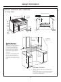
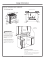
Installation
Instructions
30", 36" and 48"
Professional Ranges
Cuisinières professionnelles
de 30’’ (76 cm) 36" (91 cm)
et de 48" (121 cm)
Instructions d’installation
La section française commence à la page 24
Cocinas profesionales
de 30", 36" y 48"
Instrucciones de instalación
La sección en español empieza en la página 46
31-10689
04-08 JR
Installation Instructions
BEFORE YOU BEGIN
Vent hood Combinations:
Read these instructions completely and carefully.
It is recommended that these ranges be installed
in conjunction with a suitable overhead vent hood.
• Install a hood with at least 1200 CFM above a 48"
wide range.
• Install a hood with at least 600 CFM above a 30”
or 36” range.
Due to the high heat capacity of this unit, particular
attention should be paid to the hood and ductwork
installation to assure it meets local building codes.
•
IMPORTANT — Save these instructions for
local inspector’s use.
•
IMPORTANT — Observe all governing
codes and ordinances.
• Note to Installer — Be sure to leave these
instructions with the Consumer.
• Note
to Consumer — Keep these instructions
with your Owner’s Manual for future reference.
•
WARNING:
Completion Time — 1 to 3 hours.
Clearances to horizontal surfaces above the range,
measured to the cooking surface:
• Installations without a hood require 48” minimum
to combustibles.
• A custom hood installation with exposed
horizontal combustibles surfaces must have
an Auto-On feature.
• For other installations with a hood, refer to hood
installation instructions for specific hood
clearances.
• Proper installation is the responsibility of the
installer. Product failure due to improper
installation is not covered under the warranty.
See Owner’s Manual for warranty information.
WARNING:
This appliance must be properly grounded.
See ”Electric Supply.”
For Monogram local service in your area,
1.800.444.1845.
CAUTION:
For Monogram Parts and Accessories, call
1.800.626.2002.
These ranges weigh up to 700 pounds. Some
disassembly will reduce the weight considerably.
Due to the weight and size of the range and to
reduce the risk of personal injury or damage to
the product:
If you received a damaged range, you should
contact your dealer.
TWO PEOPLE ARE REQUIRED FOR PROPER
INSTALLATION OF 36" AND 30" RANGES.
In the Commonwealth of Massachusetts:
• This product must be installed by a licensed
plumber or gas fitter.
• When using ball type gas shut off valves, they
shall be T-handle type.
• A flexible gas connector, when used, must not
exceed 3 feet.
THREE PEOPLE ARE REQUIRED FOR PROPER
INSTALLATION OF 48" RANGES.
For Monogram Service in Canada, call
1.800.561.3344.
Leak testing of the appliance shall be conducted
according to the manufacturer’s instructions.
Installation must conform with local codes. In the
absence of local codes, the range must comply with
the National Fuel Gas Code, ANSIZ223.1/NFPA 54,
latest edition and National Electrical Code
ANSI/NFPA 70 latest addition. In Canada, installation
must conform with the current Natural Gas
Installation Code, CAN/CGA-B149.1 or the current
Propane Installation Code, CAN/CGA-B149.2, and
with local codes where applicable. This range has
been design-certified by CSA International according
to ANSI Z21.1, latest edition and Canadian Gas
Association according to CAN/CGA-1.1 latest edition.
WARNING:
All ranges can tip. Injury could result. Install the
supplied Anti-Tip Bracket provided. See instructions
in this manual or with the bracket.
2
Design Information
Installation Instructions
Step 1, Remove Packaging ..............................................11
Step 2, Move Range Indoors ..........................................12
Step 3, Install Anti-Tip Device ........................................13
Step 4, Connect Range to Gas........................................14
Step 5, Connect Electrical ................................................14
Step 6, Roll Range into Position ....................................14
Step 7, Level the Range ....................................................15
Step 8, Replace Oven Doors ............................................15
Step 9, Check Burners ........................................................16
Finalize Installation ..............................................................16
Installation Checklist ..........................................................16
Accessories..............................................................................17
Accessory Installation ................................................18–20
Gas Conversion ............................................................21-23
CONTENTS
Design Information
Models Available......................................................................3
Backsplash Accessories ......................................................3
Product Dimensions and Clearances........................4-7
Tools and Materials Required .......................................... 8
Installation Preparation
Power Supply Locations ..............................................9, 10
MODELS AVAILABLE
36" Natural Gas Models:
These Monogram ranges are factory set for either
natural gas or LP gas. Order the model for your
installation situation.
ZDP366N – 6 gas burners
ZDP364NR – 4 gas burners and grill
ZDP364ND – 4 gas burners and griddle
48" Natural Gas Models:
36" LP Gas Models:
ZDP484NG – 4 gas burners, grill and griddle
ZDP486NR – 6 gas burners and grill
ZDP486ND – 6 gas burners and griddle
ZDP366L – 6 gas burners
ZDP364LR – 4 gas burners and grill
ZDP364LD – 4 gas burners and griddle
48" LP Gas Models:
ZDP484LG – 4 gas burners, grill and griddle
ZDP486LR – 6 gas burners and grill
ZDP486LD – 6 gas burners and griddle
30" Natural Gas Model: ZDP304N
BACKSPLASH ACCESSORIES
• An adjustable 30" to 36" high backsplash with
shelf is also available. This backsplash fills in the
space between the top of the range and the
bottom of the hood. The shelf is positioned so that
heat lamps from the bottom of a Monogram
professional hood are directed towards the shelf.
30" LP Gas Model: ZDP304L
All models require 12" minimum clearance to a
vertical combustible surface at the rear. If clearance
is less than 12”, the entire surface of the back wall
above and the full width of the range must be
protected by a backsplash. The backsplash must be
constructed of non-combustible material, such as
metal, ceramic tile, brick, marble or other stone.
Two Backsplash Accessories Available:
• The 12" high stainless steel backsplash accessory
is available. Use this backsplash in combination
with a custom, non-combustible backsplash built
beyond the 12” height. The combined height of
the backsplash accessory and the custom
backsplash must reach the bottom of a hood,
or when there is no hood, to 48” above the
cooking surface.
12" High Backsplash
ZX12B48PSS, for 48" wide ranges
ZX12B36PSS, for 36" wide ranges
ZX12B30PSS, for 30" wide ranges
30" to 36" Adjustable Height
Backsplash With Shelf
ZXADJB48PSS, for 48" wide ranges
ZXADJB36PSS, for 36" wide ranges
ZXADJB30PSS, for 30" wide ranges
3
Design Information
PRODUCT DIMENSIONS AND CLEARANCES
48" Range Models
Universal Utility Locations
1”
Countertop
to Cooking
Surface
47-7/8” Width
8”
35-1/4”
to
36-3/4”
Height
6-1/2”
14”
16”
Gas/
Electric
Electric
3-1/4”
to 4-3/4”
2”
2”
48”
Toekick/leg
Height
28-1/4”
Depth
to Front
of Door
12” Minimum
to Adjacent Wall
48” Minimum
to Combustibles
WARNING:
Installations without a hood require
48” minimum to combustibles.
A custom hood installation with
exposed horizontal combustible
surfaces must have an Auto-On
feature. Refer to hood installation
instructions for specific hood
clearances.
18”
Min.
Non-Combustible
Material
13”
Max.
The surface of the entire back wall
above the range and below the
hood must be covered with a noncombustible material such as metal,
ceramic tile, brick, marble or other
stone.
12” Minimum
Each Side
48” Min.
ADDITIONAL CLEARANCES:
Allow 12" minimum clearance to an adjacent wall
on each side.
Working areas adjacent to the rangetop should have
18" minimum clearance between countertop and
the bottom of the wall cabinet.
4
Design Information
PRODUCT DIMENSIONS AND CLEARANCES
36" Range Models
Universal Utility Locations
1”
35-7/8” Width
Countertop
to Cooking
Surface
4-5/8”
35-1/4”
to
36-3/4”
Height
6-1/2”
13-3/8”
11-3/8”
Gas/
Electric
Electric
3-1/4”
to 4-3/4”
2”
2”
36”
28-1/4”
Depth
to Front
of Door
Toekick/leg
Height
12” Minimum
to Adjacent Wall
48” Minimum
to Combustibles
WARNING:
Installations without a hood require
48” minimum to combustibles.
A custom hood installation with
exposed horizontal combustible
surfaces must have an Auto-On
feature. Refer to hood installation
instructions for specific hood
clearances.
13”
Max.
18”
Min.
Non-Combustible
Material
The surface of the entire back wall
above the range and below the
hood must be covered with a noncombustible material such as metal,
ceramic tile, brick, marble or other
stone.
12” Minimum
Each Side
36” Min.
ADDITIONAL CLEARANCES:
Allow 12" minimum clearance to an adjacent wall
on each side.
Working areas adjacent to the rangetop should have
18" minimum clearance between countertop and
the bottom of the wall cabinet.
5
Design Information
PRODUCT DIMENSIONS AND CLEARANCES
30" Wide Range Models
Universal Utility Locations
1”
29-7/8” Width
Countertop
to Cooking
Surface
4-5/8”
35-1/4”
to
36-3/4”
Height
11-3/8”
7-3/8”
Gas/
Electric
Electric
6-1/2”
3-1/4”
to 4-3/4”
2”
2”
30”
28-1/4”
Depth
to Front
of Door
Toekick/leg
Height
12” Minimum
to Adjacent Wall
48” Minimum
to Combustibles
WARNING:
Installations without a hood require
48” minimum to combustibles.
A custom hood installation with
exposed horizontal combustible
surfaces must have an Auto-On
feature. Refer to hood installation
instructions for specific hood
clearances.
18”
Min.
Non-Combustible
Material
13”
Max.
The surface of the entire back wall
above the range and below the
hood must be covered with a noncombustible material such as metal,
ceramic tile, brick, marble or other
stone.
12” Minimum
Each Side
30” Min.
ADDITIONAL CLEARANCES:
Allow 12" minimum clearance to an adjacent wall
on each side.
Working areas adjacent to the rangetop should have
18" minimum clearance between countertop and
the bottom of the wall cabinet.
6
Design Information
PRODUCT DIMENSIONS AND CLEARANCES
48", 36" and 30" Range Models
10-1/2”
28-7/8”
To Front Edge
13/16”
Optional
Backsplash
Accessories
30-36”
12”
3-3/16”
Control Panel
Depth
1”
35-1/4”
to
36-3/4”
28-1/4” To
Beveled
Edge of Control
Panel Bullnose
7” Control Panel
Height
27-1/2” To
Beveled Edge –
Maximum
Adjacent Cabinet
Depth for
Flush Installation
28-1/4”
To Front of Door
12" Min. to combustibles or 0" to
a non-combustible material above
the cooking surface
31-1/16”
To Front of Handle
48-1/4”
With Oven Door Open
WARNING:
0” Clearance
to a back or
side wall below
the cooking
surface
The 12” high stainless steel
backsplash accessory must be
installed in combination with a
custom non-combustible backsplash.
The finished backsplash must cover
the entire back wall up to the bottom
of a hood, or when there is no hood,
48” to combustibles.
7
Installation Information
TOOLS REQUIRED
WB28K10553 HIGH ALTITUDE KIT
For operation above 3,000 feet, order WB28K10553
Conversion Kit. This kit includes orifices for both LP
and Natural gas operation.
Drill and
Appropriate Bits
Saber Saw
WB28K10554 DE-RATE KIT
(For a small kitchen environment.)
De-rate conversion kit for use with model
ZDP304N (natural gas only). This kit includes
orifices to reduce surface burner output
to 40,800 BTU’s.
Adjustable Wrench
Measuring Tape
1/4” Driver or Wrench
Carpenter’s Square
MATERIALS PROVIDED
Safety Glasses
Anti-Tip
Bracket, Brace
and Screws
1/2” Pipe
Elbow
Oven Rack
Lubricant
Runners
(to protect
flooring)
Phillips #2 Screwdriver
Hand Truck
Level
MATERIALS REQUIRED (not provided)
Joint
Sealant
Pipe Fittings
Shut Off Valve
5-foot maximum length, 5/8" O.D. CSA-approved flexible
metal gas supply
(3-foot maximum length in Massachusetts only)
NOTE: Purchase new flexible line; do not use
previously used flexible gas line.
8
Installation Preparation
POWER SUPPLY LOCATIONS
Gas Supply:
Electric Supply:
•The natural gas models are designed to operate
at 5" water column pressure. For proper operation,
the pressure of the natural gas supplied to the
regulator must be between 7" and 13" water
column.
•The LP models are designed to operate at 10"
water column pressure. For proper operation,
the pressure of the LP gas supplied to
the regulator must be between 11"
and 13" water column.
•A 1/2" elbow is provided for connection
to the range gas inlet, located at the rear
and near the floor.
•Locate the pipe stub on the back wall or floor
as illustrated in “Dimensions and Clearances.”
Use 5-foot maximum length, 5/8" O.D. flexible
gas supply line (3-foot in Massachusetts).
•Install a manual shut-off valve in the gas line
(not provided), in an easily accessible location.
Make sure the homeowner knows where
and how to shut off the gas supply to the range.
These ranges must be supplied with 208/240 volt,
60 Hz., and connected to an individual, properly
grounded branch circuit protected by a circuit
breaker or time delay fuse (50 amp for 48" ranges,
30 amp for 36" and 30" ranges). The receptacle
must be a NEMA 14-50R device to accept the
4-prong plug supplied with the range.
If the electrical service provided does not meet
the above specifications, it is recommended that
a licensed electrician install an approved outlet.
•Locate the electric supply as illustrated
in “Dimensions and Clearances.”
WARNING
The range is equipped for use with an electrical
supply which uses a separate grounding conductor
(4 wire system).
If this range must be connected to an electrical
system which utilizes a single conductor for ground
and neutral (3 wire system), the grounding jumper
at the terminal block must be connected.
The grounding jumper is located to the right
of the terminal block.
The access plate
is on the back
of the range.
See 3-wire power cord installation on the next page.
9
Installation Preparation
4-WIRE POWER CORD INSTALLATION
3-WIRE POWER CORD INSTALLATION
NOTE: A 4-wire cord is connected to the range
at the factory. Use the following steps to change
an existing installation from a 3-wire cord back
to a 4-wire cord.
NOTE: A 4-wire cord is connected to the range
at the factory. Use the following steps to change
the range to a 3-wire cord.
WARNING
WARNING
The neutral or ground wire of the power cord
must be connected to the neutral terminal located
in the center of the terminal block. The power leads
must be connected to the lower left and the lower
right terminals of the terminal block.
•Remove the ground strap (located at the right
side of the terminal block) and connect between
the center lower portion of the terminal block
to the frame of the range.
•Remove the 3 lower terminal screws from
the terminal block. Insert the 3 terminal screws
through each power cord terminal ring and
into the lower terminals of the terminal block.
Be certain that the center wire (white/neutral)
is connected to the center lower position
of the terminal block. Tighten screws securely
into the terminal block.
DO NOT remove the ground strap connection.
The neutral wire of the supply circuit must
be connected to the neutral terminal located
in the lower center of the terminal block.
The power leads must be connected
to the lower left and the lower right
terminals of the terminal block. The 4th
grounding lead must be connected to
the frame of the range with the ground
plate and the ground screw.
•Remove the 3 lower terminal screws from
the terminal block. Remove the ground screw
and ground plate and retain them.
•Remove the ground strap. DO NOT DISCARD
THE GROUND STRAP OR ANY SCREWS.
•Insert the one ground screw into the power cord
ground wire terminal ring, through the ground
plate and into the frame of the range.
•Insert the 3 terminal screws (removed earlier)
through each power cord terminal ring and
into the lower terminals of the terminal block.
Be certain that the center wire (white/neutral)
is connected to the center lower position
of the terminal block. Tighten screws securely
into the terminal block.
Terminal Block
(appearance
may vary)
Neutral
Terminal
Ground Strap
Before
Ground
Plate
or
Terminal
Block
Ground Strap
Ground
Strap
Neutral
Terminal
After
Neutral Terminal
Terminal
Block
Power Cord
Ground Plate
(grounding to
range)
Ground
Screw
10
Installation
STEP 1
REMOVE PACKAGING
CAUTION
• Open oven door(s) and remove packaging.
Remove shelf holding broiler pan, tape, literature
package, shelf lubricant and probe.
Stand clear. The ends of the cut metal banding may
snap toward you.
•Cut the metal banding. Lift the carton straight up.
•Locate the two runner strips from the top
of the packaging. These strips will be used to
protect the kitchen floor during installation.
•Remove corner posts. Dispose of packaging
materials.
CAUTION
Doors and passageways leading to the installation
location require at least 32" opening. If the opening
is less than 32", the oven door(s) and control knobs
must be removed.
REMOVE THE OVEN DOOR(S) ONLY IF NECESSARY to
move the range through the doorways. To prevent
damage to the sides of the range, it will be
necessary to pad the corners beneath the straps
on the hand-truck.
•Remove grill/griddle covers, grill grate and burner
grates.
•Lift out cast-iron griddle flue cover, grease troughs
and pads.
•Cut the ties holding the grill grate to the grill frame.
Slot
Griddle Flue Cover
Hinge
Lock
Ties
Grease Troughs
To remove the oven door(s):
• Fully open the door.
• Each hinge has a hinge latch. Close the hinge
latch down against the door frame.
• Firmly grasp the door at the top sides.
• Close the door to the near-vertical position.
• Lift the door up and pull straight out.
• Remove the control knobs by pulling them
straight out.
•Lift off burner caps and remove foam pad,
then lift off burner heads and remove foam pad.
Remove Foam Pads
11
Installation Preparation
STEP 2
MOVE THE RANGE INDOORS
4 Slide the blade of the hand-truck beneath
the front and back legs.
1 Tilt the range forward on the skid.
Toekick
2 Lift the toekick out of the foam base.
Insert Blade Under
the Range Legs
IMPORTANT: Place the hand-truck straps below
the oven door handles.
5 Tilt the range to lower the hand-truck wheels
off the skid.
Toekick
Hand-Truck
Straps Below
Oven Door
Handles
3 Tilt the range to one side and remove the foam block.
6 Move the range indoors. Position the range
in front of the installation location.
7 Place the appliance runners on the floor
at the left and right sides of the opening.
The runners provide a surface for rolling
the range into the final position and will protect
the floor finish. The runners must be removed
before leveling the range.
Range
Range
Opening
Opening
Runners
Runners
for Support
Rolling
To
the Range
Leveling
Legs
into Position
12
Panel
Installation
STEP 3
INSTALL ANTI-TIP DEVICE
• All ranges can tip.
• BURNS or other SERIOUS INJURIES
can result.
• INSTALL and CHECK the ANTI-TIP
bracket following these instructions.
• Attach the Anti-Tip Brace onto the bottom
of the range in the recessed area. Install 2 hex
screws (provided) through the brace and into
the range.
To reduce the risk of tipping the range, the range
must be secured by a properly installed anti-tip bracket.
See installation instructions shipped with the bracket
for complete details before attempting to install.
To check if the bracket is installed and engaged properly,
carefully tip the range forward. The bracket should stop
the range within 4 inches. If it does not, the bracket must
be reinstalled.
If the range is pulled from the wall for any reason,
always repeat this procedure to verify the range
is properly secured by the anti-tip bracket.
If your range has no anti-tip bracket, call 1.800.626.8774
to receive one at no cost.
If the Anti-Tip device supplied with the range does not fit this
application, use the universal Anti-Tip device WB2X7909.
Read the AHAM Anti-Tip Safety Brochure packed
with the bracket.
NOTE: This Anti-Tip device may be installed on the
opposite side of the range.
Hex Screws
Anti-Tip Brace
Alternate Brace
Position
• Measure and mark Dimension A (see table below)
from the left (or right) side of the installation
location. If the countertop has an overhang,
add that dimension to Dimension A.
• Place the Anti-Tip Bracket against the floor
and back wall at the marked location. Mark screw
holes for fastening the bracket to the wall sole plate
and the floor.
• Drill 1/8" pilot holes at a 20° angle.
• Secure the bracket to the wall and/or floor with
at least 2 wood screws (provided).
For Concrete or Cement Construction: You must
use appropriate fastening hardware (not provided).
Anti-Tip Parts Provided
4 Wood Screws
Anti-Tip Bracket
3 Hex Head Screws
(2 required, 1 extra)
Range
30”
36”
48”
Anti-Tip Brace
Anti-Tip Bracket
A
5-1/16”
5-1/16”
8-1/4”
Wall Sole Plate
A
AHAM Anti-Tip
Safety Brochure
13
Installation
STEP 4
CONNECT RANGE TO GAS
STEP 6
ROLL RANGE INTO POSITION
WARNING
WARNING
Do not use a flame to check for gas leaks.
The Anti-Tip Bracket must be properly installed
to prevent tipping of the range. Failure to do so
can cause serious damage or injury.
• Check to be sure the appliance runners are
beneath the wheels.
• The range is shipped with the wheels in the down
position. Carefully roll the range into position,
being careful not to entangle or pinch the power
cord and flexible gas tubing.
• Remove the runners beneath the range.
Assure that gas supply is turned off
at the shut-off valve:
• Apply pipe thread sealant to the gas inlet located
at the back of the range. Install the 1/2" pipe
elbow (provided) to the gas inlet.
• Connect 5/8" O.D. flexible metal connector
to gas inlet. Connect the other end of the flexible
connector to the house gas supply.
• Turn on the gas and check for leaks:
– Use a liquid leak detector at all joints
and connections in the system.
Be sure Anti-Tip
Bracket is engaged
with the brace
on the range.
Gas
Inlet
IMPORTANT: Disconnect the range and the
individual shut-off valve from the gas supply piping
system during any pressure testing of that system
at test pressures greater than 1/2 psig. Isolate the
range from the gas supply piping system by closing
the individual manual shut-off valve to the range
during any pressure testing of the gas supply piping
system at test pressures equal to or less than
1/2 psig.
NOTE: This range is equipped with a gas shut-off
valve located on top of the range, beneath the rear
vent. This shut-off valve is to be used in the event
that service is required in the future.
STEP 5
CONNECT ELECTRICAL
• Plug power cord into properly grounded
receptacle.
• Verify that power is connected by opening
the oven door or press the button on the left side
of the control panel to illuminate the accent
lighting.
14
Installation
STEP 7
LEVEL THE RANGE
STEP 7
WARNING
LEVEL THE RANGE (cont.)
REAR LEG ADJUSTMENT
•Remove two screws from rear vent trim. Slide vent
trim forward, then lift up to remove.
•Find the two rear leg extension rods. Use a 1/4"
driver or wrench to adjust the left or right rear legs.
The range must be level and be supported
by the legs—not the wheels. The range could move
if the wheels make contact with the floor. Be sure all
legs make contact with the floor in any installation.
•All legs must be leveled after the product is
installed.
•Check to be sure the adjoining cabinets/
countertops are level, front to back and left
to right across the opening of the range.
•Measure the distance from the floor to the top
of the countertop in the left and right rear corners.
•Adjust the height of the range to countertop height
or higher.
IMPORTANT: This range should always be installed
at countertop height or higher. DO NOT INSTALL
THE RANGE LOWER THAN ADJACENT COUNTERTOP
HEIGHT. The range must be supported by all 4 legs,
regardless of countertop height.
Rear Vent Trim
Rear Leg
Extension Rod
•Replace the rear vent trim using the original screws.
STEP 8
REPLACE OVEN DOOR(S)
Skip this step if oven doors are in place.
IMPORTANT: Do not lift the door by the handle.
To replace the oven doors:
•Firmly grasp the door at the top sides.
This is critical.
•Approach the range with the door angled
in a vertical position.
•Guide the hinges into the slots.
•Push the door in firmly while opening.
•Once in position, open the door completely.
Push the hinge locks back in and toward
the front frame.
FRONT LEG ADJUSTMENT
•Slide front cylinders up to adjust front leveling
legs. Be careful not to damage cylinder.
•A leveling leg wrench is supplied. Reach under
the front of the range near the right side. Locate
and remove a thumb screw, then slide wrench out
of the slot.
Thumb Screw
Slide leg
cylinder up.
•Use the supplied wrench to turn the front leveling
legs. Turn clockwise to raise the range above the
wheels. Turn counterclockwise to lower the legs.
CAUTION:
Take care when replacing
the oven doors. If the hinge latch is not securely
locked, the hinge may snap back and separate.
If the hinge separates, you must apply pressure
(possibly with your foot) to press it back together
and then engage the hinge latch.
•Be sure to return the wrench to its storage slot
for future use.
15
Installation
STEP 9
FINALIZE INSTALLATION
CHECK BURNERS
Place the burner grates over the burners.
The grates should be seated and should not rock.
Check to be sure that burner heads and caps
are securely seated.
The griddle is secured with screws. It is designed
to be stationary and should not be removed.
The griddle has two leveling screws beneath
the rear flue cover that can be used to adjust
to the desired slope.
Burner Cap Properly Seated
Griddle Flue Cover
Burner Cap Not Properly Seated
•Check for proper ignition:
– Push in one control knob and turn to LITE
position.
– The igniter will spark and the burner will light;
the igniter will cease sparking when the burner
is lit.
– First test may require some time, while air
is flushed out of the gas line.
– Turn knob to OFF.
– Repeat the procedure for each burner.
Leveling Screws
Clamping Screws
IMPORTANT: If the igniter electrodes continue
to spark after the burners are lit, check that
each burner component is assembled properly.
Refer to the Owner’s Manual.
The two inner screws are clamping screws for
securing the griddle in place. Loosen these two
screws before leveling. Do not remove these two
screws.
•Burner flames should be blue and stable with no
yellow tips, excessive noise or lifting of the flame
from the burner. If any of these conditions exist,
check that the burner ports are not blocked.
If one of these conditions continues, call for
service.
The two outer screws are leveling screws. Do not
remove these two screws. They can be turned to
level the griddle or to provide a forward slope to
help grease and oils drain away from the food
being cooked.
After leveling the griddle, hand-tighten
the clamping screws; do not over-tighten.
INSTALLATION CHECKLIST
❑ Make sure all controls are left in the OFF position.
❑ Make sure the flow of combustion and ventilation
air to the range is unobstructed.
❑ Recheck Steps:
Double check to make sure everything in this
manual has been completed. Rechecking steps
will ensure safe use of the range.
NOTE: The rating plate is located on the bottom
of the control panel and is visible when the oven door
is opened. The model and serial number is behind
the left knob and is visible when the knob is pulled off.
16
Installation
ACCESSORIES—TOEKICK (provided)
•Install the toekick after the range has been leveled.
•Measure the distance between the floor
and the bottom of range.
•Loosen the two screws on each end. Adjust
the toekick height by sliding the upper and lower
pieces apart to 1/8" less than the measured height.
•Secure the top and bottom sections by tightening
the 2 screws on each end.
•Push toekick against range leg until clip snaps
to legs.
NOTE: Be sure the toekick snaps securely to the leg.
Top of
Toekick
Bottom
of Toekick
Screw
Push
Push
17
ZX12B30PSS, ZX12B36PSS, ZX12B48PSS Accessory Installation
OPTIONAL ACCESSORIES—12" HIGH BACKSPLASH
INSTALL 12" BACKSPLASH
WARNING:
WARNING:
To prevent ignition of combustible materials,
the entire back wall above the range must
be protected by a backsplash constructed
of non-combustible material.
This backsplash must
be securely fastened to the wall. Failure to do
so could result in damage or personal injury.
• Install and level the range or rangetop and the
range hood according to the installation
instructions.
• Remove the backsplash packaging and
protective film.
• Use a level to pencil a horizontal line on the wall,
1/8" above the range or rangetop. The 1/8" gap
allows the cover panel to overlap the wall support
panel.
• Locate wall studs on each side. Where studs are not
available, plan to use wall anchors (not provided).
• Align the wall support panel on the marked
horizontal line and centered left to right.
• The wall support panel must be secured to the wall
at all 4 corners. Use wood screws (provided) or wall
anchors (not provided) to secure the support panel
to the wall.
• Place the cover panel over the wall support
panel and secure with Torx screws (provided).
Install 2 screws on each side.
This stainless steel backsplash accessory
must be installed in combination with a custom,
non-combustible backsplash built beyond
the 12" height of the backsplash.
BEFORE YOU BEGIN
Read these instructions completely
and carefully.
IMPORTANT: Save these instructions for local
inspector’s use.
IMPORTANT: OBSERVE ALL GOVERNING CODES
AND ORDINANCES.
NOTE TO INSTALLER: Be sure to leave these
instructions with the Consumer.
NOTE TO CONSUMER: Keep these instructions
with your Owner’s Manual for future reference.
This kit provides for the installation of a 12" high
backsplash for 30", 36" or 48" Monogram
Professional Ranges and Rangetops.
Install 4 Wood
Screws
Wall Support
Panel
1/8″
TOOLS AND MATERIALS REQUIRED
•
•
•
•
•
•
Gloves to protect against sharp edges
T-15 and #2 Phillips screwdrivers
Wall Support
Panel
Drill with 3/32" and 9/64" bits
Safety glasses
Level
Cover Panel
Pencil
Install T-15
Screws
Wall
Support
Panel
This Kit Includes
• Wall support panel
• Cover panel
• Hardware package with
– 5 Stainless Steel Torx 15 #8
self-tapping screws
– 5 Phillips #2 pan head wood
#10 screws
Center
Arrow
Hardware
Package
761Dia65
18
Cover Panel
ZXADJB30PSS, ZXADJB36PSS, ZXADJB48PSS Accessory Installation
ACCESSORIES—30" TO 36" ADJUSTABLE BACKSPLASH (not included)
INSTALL THE WALL SUPPORT PANELS
WARNING:
WARNING:
To prevent ignition of combustible materials,
the entire back wall above the range must
be protected by a backsplash constructed
of non-combustible material.
The wall support panels
must be securely fastened to the wall. Failure to
do so could result in damage or personal injury.
IMPORTANT: This backsplash is designed to cover the wall
between the bottom of the hood and the top of the range.
The vent hood should be installed over the rangetop or
range before installing this backsplash.
• Install and level the Range/Rangetop according
to the product installation instructions.
• Remove backsplash packaging and protective film.
• Locate wall studs on each side. Where studs are not
available, plan to use wall anchors (not provided).
• Use a level to pencil 2 horizontal lines on the wall,
one 1/8" below the vent hood and the other 1/8" above
the Range/Rangetop. This 1/8" space allows the cover
panels to overlap the wall supports.
• Secure the top wall support panel to the wall with 4 wood
screws, through the outermost studs.
• Use 4 wood screws to secure the bottom wall support
panel. The center slot should be positioned at the top.
The gap between the top and bottom support panels
will be covered by the top cover with shelf.
BEFORE YOU BEGIN
Read these instructions completely
and carefully.
IMPORTANT: Save these instructions for local
inspector’s use.
IMPORTANT: OBSERVE ALL GOVERNING CODES
AND ORDINANCES.
NOTE TO INSTALLER: Be sure to leave these
instructions with the Consumer.
NOTE TO CONSUMER: Keep these instructions
with your Owner’s Manual for future reference.
• This backsplash adjusts to fit the space between
the top of the range and the bottom of the hood,
from 30" Min. to 36" Max. height.
Secure the top
panel to the wall
with 4 wood
screws
• Maximum shelf load-bearing weight is 40 lbs.
1/8″
TOOLS AND MATERIALS REQUIRED
•
•
•
•
•
•
Gloves to protect against sharp edges
T-15 and #2 Phillips screwdrivers
Drill with 3/32" and 9/64" bits
Safety glasses
Level
Top Cover
with
Shelf
Pencil
Center
Arrow
Wood Screws
Top Wall
Support
1/8″
This Kit Includes
•
•
•
•
•
Top wall support
Bottom wall support
Bottom Cover
Top cover with shelf
Bottom cover
Bottom Wall Support
Hardware package with
– 9 Stainless Steel Torx 15 #8
self-tapping screws
– 9 Phillips #2 pan head wood #10 screws
– 3 Stainless Steel #2 truss head
Hardware
#10 screws (for alternate
Package
761Dia65
installation method)
19
Wood Secure
Screws the bottom panel
to the wall with
4 wood screws
ZXADJB30PSS, ZXADJB36PSS, ZXADJB48PSS Accessory Installation
INSTALL COVER PANELS
INSTALL COVER PANELS (cont.)
See alternate method if side access is blocked.
ALTERNATE METHOD: When side access is blocked
• Hold the bottom cover over the bottom support
while driving one screw (provided) into each side.
• Place the top cover with shelf over the top wall
support. If you have access to the sides, secure
the panel with two screws on each side.
• Secure the top cover with shelf to the top
support with screws through the front of the panel,
at the top corners. Use one screw on each side.
• Install bottom cover over the bottom support while
driving one screw into each side.
• Hold top cover in place while marking screw
locations, just below shelf support and onto bottom
cover.
• Remove the shelf and drill a 9/64" diameter
hole in the pencil-marked locations.
• Mount the top cover over the top support
and secure the front cover with screws through
the drilled holes on each side.
• Install screws through each top corner.
Mark Screw Locations
for Alternate Method
Cover Panel
Install
Screw
Install
Screw
Install Corner Screws
Install Screw
on Each Side
Install Screw in Top Corner on Each Side
Shelf
20
Installation
Instructions
Convert Natural Gas to LP Gas Operation
Convert LP Gas to Natural Gas Operation
2 CONVERT THE REGULATOR
WARNING: This conversion must
be performed by a qualified installer or gas supplier
in accordance with the manufacturer’s instructions
and all codes and requirements of the authority having
jurisdiction. Failure to follow instructions could result
in serious injury or property damage. The qualified
agency performing this work assumes responsibility
for the conversion.
Disconnect all electrical power at the main circuit
breaker or fuse box.
A. Remove the rear vent Range Regulator
trim (on ranges only)
to access the
regulator. The
Rangetop regulator is
on the left bottom
corner.
B. Shut off the gas supply by closing the manual shut-off
valve in the unit or at the wall.
C. Convert the pressure regulator:
• Unscrew the cap with plunger.
• Place your thumb against flat side of the plunger and
press down to snap the plunger out of the cap.
• Carefully look at the plunger to locate the NAT
or LP position.
NAT
Plunger
LP
NAT
NAT. Position
LP Position
DOWN
FOR OFF
Pressure Regulator
1/4” and 7mm Nutdrivers
Crescent Wrench
LP
LP
TOOLS YOU NEEDED FOR CONVERSION
Gasket
Cap
NAT
• Turn the
plunger
over so
that the
desired gas
is showing
near the
bottom.
LP
WARNING:
The following adjustments must
be made before turning on the burner. Failure to do so
could result in serious injury. Be sure pressure regulator
has been converted as described in Step 2.
NAT
WARNING:
The rangetop, as shipped from
the factory, is set for use with its intended gas. If you
wish to use your rangetop with the alternate gas, you
must first replace the orifices and convert the pressure
regulator.
• Snap the plunger back into the cap.
• Screw the cap back onto the regulator.
Small Flat-Head Screwdriver
(2 to 2.4 mm or 3/32” tip size,
60 mm long)
Safety Glasses
3 CHANGE BURNER ORIFICES
1/2” Deepwell
Socket Wrench
Small Pliers
1 ORIFICE HOLDER
Griddle
Orifice
Burner Cap
INSTALLATION TIP: First remove all
orifices and then start replacing them.
This will help to prevent the possibility
that some may not be replaced.
Burner
A. Remove the burner grates,
Head
burner caps and burner heads.
B. Loosen the top burner
Spark
Igniter
orifices using a 7 mm
nut driver. Use small
Burner Base
pliers to carefully lift out the orifices.
The main orifice is located
low in the center of the
burner, while the simmer
Simmer
orifice is located higher
Orifice
beside the center
of the burner.
Main
Philips
Screwdriver
Grill
Orifice
The range orifice holder
is located behind the front
access panel at the bottom
of the range.
Burner Orifices
The rangetop orifice holder
is located inside the range insulation cover.
Additional orifices may be present. Use only the orifices
specified in the instructions for your range or rangetop.
Orifice
21
Installation Instructions for Gas Conversion
3 CHANGE BURNER ORIFICES (cont.)
4 CHANGE GRILL ORIFICE (if present)
IMPORTANT: Find your model number below. Read
each orifice label to identify and install them in the
exact locations shown.
Locate the 1–1/2” long Grill orifice.
Select for your gas type. LP—.047, NAT—.067
ZDP304 SIMMER ORIFICES
A. Remove the grill cover,
grates and grate frame. Lift
the radiant baffle straight
up and off.
A 34SL or 51SN orifice
will be used on all burners.
ZDP304 MAIN ORIFICES
A 84XL or
126HXN orifice
will be used
on these three
burners.
Use a 108XL
or 190XN orifice
for the right
front burner.
B. Remove the 2 hex
head screws from
2
the top of the igniter. Remove
hex head
screws
• Remove one screw
from each side of
the burner surround.
• Lift out the surround.
MAIN
ORIFICES
Igniter
Burner
C. Carefully push the
Surround
igniter aside and
under
the burner.
Do not pull or pinch
the wire.
Remove 4 burner
attachment screws,
2 at the front and 2
at the back. Slide the
burner assembly
toward the back and
out of the gas inlet.
ZDP364, ZDP366, ZDP484, ZDP486
SIMMER
ORIFICES
Surround
Screws
A 34SL or 51SN orifice
will be used on all
burners.
Use 108XL or
190XN orifices
for all burners.
D. Use a 1/2" deep well
socket to remove
and replace the orifice .
Reverse these
steps to re-assemble
the grill. Be sure to
place the unused
orifice in the holder
for possible future use.
A. Return the unused orifices to the holder. Reattach
the holder and the instruction sheet with screw
in the original storage location.
B. Replace the burner heads, caps and top grates.
On range models, replace rear vent trim.
22
Burner
Assembly
Front of Range
Installation Instructions for Gas Conversion
6 ADJUST BURNER FLAMES
5 CHANGE GRIDDLE ORIFICE (if present)
Locate the 3/4” long Griddle orifice.
Select for your gas type. LP—.047, NAT—.076
Normally, burners do not need further adjustment.
Make adjustments only when necessary.
A. Lift off
the griddle flue
cover. Remove
Griddle Flue Cover
the 2 inside
A
clamping
screws.
B. Use a pad or
piece of
carton to
protect
Leveling Screws
the adjacent
surface. Slide
the griddle
Clamping Screws
toward
the rear
and out of
B
the hold-down tabs along
the bottom.
C. CAREFULLY lift and hold
the griddle. A thermostat
capillary is routed through
a clip. Gently lift the griddle
to one side and slip the
capillary out of the clip.
C
D. Lay the griddle
on the padded surface.
Do not disconnect or pull
on the capillary.
E. Remove the 2 burner
hold-down screws
at the rear of the burner.
D
• Pull the burner straight
back toward the rear
and out of the gas inlet.
F. Use a 1/2" deep well socket
to remove and replace
the orifice.
A. Turn on the gas. Plug in electrical cord.
B. Turn all burners on highest setting and check
the flames. They should be blue in color. When
using LP gas, the flames may have some yellow
tipping at the ends of the flame. Foreign particles
in the gas line may cause an orange flame at first,
but this will soon disappear.
C. Turn the burner knob to “LO” while observing the
flame.
Adjust the setting of the upper row of flames using
the valve bypass screw as follows:
Adjustments must be made with two other burners
in operation on a medium setting. This prevents
the upper row of flames from being set too low,
resulting in the flame being extinguished when
other burners are turned on.
D. To adjust the flame, remove the knobs. Insert a small
flat-blade screwdriver into the hole in the center
of the valve stem to engage screw.
E
Back of Range
F
NOTE: Remove
the 2 screws
positioned on
the inside only.
Do not remove
the outermost
screws—they
are for leveling.
Capillary
• If the flames are too small or flutter,
turn the screw counterclockwise.
Front of Range
• If the flames are too large, turn the screw
clockwise.
E. Make the adjustment by slowly turning the screw
until flame appearance is correct.
Reverse these steps to re-assemble the griddle. Push excess
capillary back into the entry hole. Route the thermostat
capillary so it is held by the clip. Place the unused orifice in
the holder for possible future use.
Once the conversion is complete and checked, fill out the conversion label and affix the label near the rating label. For ranges,
place the label beneath the control panel. For rangetops, place the label on the bottom of the unit.
23
NOTE: While performing installations described in this book,
safety glasses or goggles should be worn.
For Monogram® local service in your area, call
1.800.444.1845.
NOTE: Product improvement is a continuing endeavor at
General Electric. Therefore, materials, appearance and
specifications are subject to change without notice.
REMARQUE: lorsque vous procédez aux installations
abordées dans ce manuel, il est fortement recommandé
de porter des lunettes de sécurité.
Pour contacter le service de dépannage Monogram
le plus proche de chez vous, veuillez appeler
le 1.800.444.1845.
REMARQUE: la philosophie de General Electric fait la part
belle à l’innovation. C’est pourquoi les matériaux, les
caractéristiques et l’apparence extérieure peuvent faire
l’objet de modifications sans préavis.
NOTA: Mientras efectúa las instalaciones descriptas en este
libro, deben utilizarse gafas o lentes de seguridad.
Para servicio técnico local Monogram® en su área,
llame al 1.800.444.1845.
NOTA: La mejora de los productos es un esfuerzo continuo
para General Electric. Por lo tanto, los materiales,
la apariencia y las especificaciones pueden sufrir cambios
sin previo aviso.
GE Consumer & Industrial
Printed in Mexico
Appliances
General Electric Company
Louisville, KY 40225
ge.com