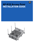
1
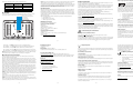
(5)
Secure the AP-5181 to the pole.
2.
Drill four holes in the wall that match the screws and wall plugs.
3.
Secure the bracket to the wall.
4.
Attach the square mounting plate to the AP-5181 with the supplied screws. Attach the
AP-5181 to the plate on the wall.
5.
Secure the AP-5181 to the bracket. Fit the edges of the V-shaped clamp parts into the
slots on the flat side of the rectangular plate.
1.
Ensure the AP-5181 is oriented properly, and attach the bracket to a wall with flat side
flush against the wall. Position the bracket in the intended location and mark the positions of the four mounting screw holes.
Mounting the AP-5181 on a Wall
(6)
ML-2499-FHPA5-01R
Omni-Directional
5.0
ML-2499-FHPA9-01R
Omni-Directional
9.0
ML-2452-PNA7-01R
Panel (Dual-Band)
8.0
ML-2452-PNA5-01R
Sector (Dual-Band)
6.0
Part Number
Antenna Type
Nominal Net Gain (dBi)
Antenna Specifications
The AP-5181 2.4 GHz antenna suite includes the following models:
Electrical Specifications
Operating Voltage
Operating Current
48Vdc (Nom)
200mA (Peak) @ 48Vdc/170mA (Nom) @ 48Vdc
Environmental Specifications
Temperature
-30°C to 55°C (Operating), -40°C to 85°C (Storage)
Humidity
5% to 95% Non-condensing (both Operating and Storage)
Altitude
8,000 feet/2438 m @28°C (Operating)
15,000 feet/4572 m @12°C (Storage)
Electrostatic Discharge
15kV (air) @ 50% rh, 8kV (contact) @ 50% r
Drop
Bench drop 36 inches to concrete
Wind Blown Rain
40 MPH @ 0.1inch/minute, 15 minutes
Rain/Drip/Spill
IPX6 Spray @ 4L/minute, 10 minutes
Dust
IP5X 20mb vacuum max, 2 hours, stirred dust, .88g/m^3
12 inches long x 8.25 inches wide x 3.5 inches thick
Aluminum
4 lbs.
Service Information
Before using the unit, it must be configured to operate in the facility’s network and run your
applications. If you have a problem running your unit or using your equipment, contact your
facility’s Technical or Systems Support. If there is a problem with the equipment, they will
contact the Motorola.
Austria/Österreich
1-800-672-906
Australia
Asia/Pacific
0800 328 2424
United Kingdom
Canada
1-800-653-5350
1-631-738-2400
United States
905-629-7226
To the Installer
91 324 40 00
Inside Spain
Spain/España
11-8095311
South Africa
+47 2232 4375
Norway/Norge
315-271700
Netherlands/Nederland
5-520-1835
Mexico/México
2-484441
Italy/Italia
6074-49020
Germany/Deutschland
01-40-96-52-21
France
9 5407 580
Finland/Suomi
7020-1718
Denmark/Danmark
1-505-5794-0
Safety Information
This guide is intended for the technician responsible for installing the AP-5181 model access
point. It assumes the technician is familiar with basic Ethernet LAN-based networking and
device installation concepts. This guide provides specifications, procedures and guidelines to
use during the installation process. This guide does not provide site-specific installation
procedures. For detailed site-specific installation procedures, refer to the site-specific
documentation derived from site survey and site network analysis.
AP-5181 Access Point
Installation Guide
+65-6796-9600
84452900
Sweden/Sverige
Place the V-shaped bracket clamp parts around the pole and tighten the nuts just
enough to hold the bracket to the pole. (The bracket may need to be rotated around the
pole during the antenna alignment process).
Physical Specifications
Dimensions
Housing
Weight
Technical Specifications
1-800-347-0178 Inside US
+1-954-255-2610 Outside US
2.
Note: The AP-5181 tilt angle may need to be adjusted during the antenna alignment process.
Verify the antenna polarization angle when installing, and ensure the antennas are oriented
correctly in respect to the AP-5181's coverage area.
Latin America
Sales Support
(4)
Caution: The 2.4 and 5.5 GHz antenna models listed are rated for the AP-5181 model access
point and its intended outdoor deployment. The models listed are not intended for use on an
AP-5131 model access point.
Attach the AP-5181 and mounting plate to the bracket already fixed to the pole. If
necessary, use the “U-bracket” (included in the mounting kit), in conjunction with the
band clamp, to expand the diameter of the bracket to a maximum if 18 inches.
Ensure the AP-5181 is oriented properly, and fit the edges of the V-shaped clamp parts
into the slots on the flat side of the rectangular plate.
Contact local distributor or call
+44 118 945 7360
5.
4.
Attach the square mounting plate to the access point with the supplied screws.
Fit the edges of the
V-shaped part into the slots
1.
Mounting the AP-5181 on a Pole
Europe/Mid-East
Distributor Operations
(3)
The mounting bracket has four parts. One rectangular plate used for pole and wall mounting,
one square plate that attaches directly to the AP-5181 and two plates forming an adjustable
V-shaped clamp for pole mounting.
The AP-5181 can be mounted to a pole (1.5 - 18 inches in diameter) or to a wall. The AP-5181
Wall Mounting Kit (Part No. KT-5181-WP-01R) is not included with AP-5181 and must be
ordered separately.
Mounting the AP-5181
Attach the square
plate to the bridge
3.
Tighten the
securing bolts
The AP-5181 has a separate LAN and WAN port for connecting to the network and receiving
power (over the AP-5181’s LAN port only). The AP-5181 has four antenna connectors (on top)
supporting 802.11a and 802.11g antenna options. However, the AP-5181 antenna suite is
designed for outdoor deployments, so the existing AP-5131 antenna suite should not be used
with an AP-5181. The AP-5181’s mode of operation is identical to the AP-5131’s.
Product Description
Note - This AP-5181 Installation Guide is intended to assist installers with the installation of
the AP-5181. Once secured in its intended operational position, refer to the AP-51xx Product
Reference Guide for detailed instructions on configuring the access point’s feature set. For
more information, go to http://www.symbol.com/manuals.
Verifying Package Contents
Inspect the contents and report any missing or damaged items to your sales representative.
The AP-5181 access point ships with the following components:
+34 91 324 40 00
Outside Spain
• 1 AP-5181 802.11 a+bg dual-radio access point (AP-5181-13040-WWR)
• 1 AP-5181 Installation Guide (this document)
• 1 set of cable connectors
• 3 antenna connector dust covers
• 2 connector cover AP67 jacks, plus chain_LTW-M9/14-SB
• 1 Waste Electrical and Equipment (WEEE) addendum
For the latest version of this guide go to http://www.symbol.com/manuals.
Note: A RJ-45 to Serial (9-pin D) cable is required to make a connection to the AP-5181’s
Console port. This cable is not supplied and must be provided by the customer.
To mount the AP-5181 access point to a pole (1.5 - 18 inches in diameter) or wall, an AP-5181
Mounting Kit (Part No. KT-5181-WP-01R) can be separately ordered. This kit contains the
brackets and accessories required to mount the access point.
MOTOROLA INC.
1303 E. ALGONQUION ROAD
SCHAUMBURG, IL 60196
www.motorola.com
The AP-5181 is a ruggedized access point designed for outdoor deployments. The AP-5181
employs a dual-mode simultaneous 802.11a and 802.11g radio solution. Unlike the AP-5131
model access point, there is just the one dual-radio mechanical version of the AP-5181 (no
single radio model is available).
Introduction
Before operating any equipment, review this document for any hazards associated with
installation and use of the device. Also, review standard practices for preventing accidents.
• Only trained and qualified personnel should install and remove the Power Injector.
• The power cord must be a three-conductor type (two current carrying conductors and one
ground conductor) terminated on one end by an IEC 60320 appliance coupler (for Power
Injector connection) and on the other end by a plug containing a ground (earth) contact.
• The power cord must be rated for a minimum of 250VAC RMS operation, with a minimum
rated current capacity of 5A [or a minimum wire gauge of 18AWG (0.75mm²)].
• The AC wall-socket outlet must be near the Power Injector and easily accessible.
• The Power Injector Data and Data & Power interfaces are qualified as SELV (Safety
Extra-Low Voltage) circuits according to IEC 60950. These interfaces can only be
connected to SELV interfaces on other equipment.
Warnings
• Read the installation instructions before connecting the Power Injector to a
power source.
• Follow basic electricity safety measures whenever connecting the Power Injector to its
power source.
• This product relies on the building installation for short-circuit (over current) protection.
Ensure a fuse or circuit breaker no larger than 120 VAC, 3A U.S. (240VAC, 1.5A
international) is used on the phase conductor.
• A voltage mismatch can cause equipment damage and could pose a fire hazard. If the
voltage indicated on the label is different from the power outlet voltage, do not connect
the Power Injector to that particular outlet.
• The Power Injector Data In and Data & Power Out ports are shielded RJ-45 sockets.
Only RJ-45 data connectors should be connected to these sockets.
If installing the AP-5181 in an outdoor area prone to high winds and rain, Motorola
recommends using the AP-5181 Heavy Weather Kit (Part No. KT-5181-HW-01R).
This kit affords additional protection to shield an AP-5181 from high wind and water
damage as a result of driving rain.
If using a single-port Power-Over-Ethernet solution to supply power to the AP-5181,
Motorola recommends using the AP-5181 Power Tap (Part No. AP-PSBIAS-5181-01R).
This single-port power injector is designed specifically for outdoor use with the AP-5181.
72-117415-01
Revision A October 2008
(1)
(2)
The AP-5181 5.2 GHz antenna suite includes the following models:
ML-5299-FHPA6-01R
Omni-Directional
6.0
ML-5299-FHPA10-01R
Omni-Directional
10.0
Caution - For Power Tap installations, a electrician is required to open the unit, feed the power
cable through the Line AC connector, secure the power cable to the unit’s three screw
termination block and tighten the unit’s Line AC clamp (by hand) to secure the power cable. Only
a certified electrician should conduct the installation. Additionally, an electrician must attach a
ground cable between the EARTH GROUND connector (on the back of the unit) to a suitable
earth ground connection as defined by your local electrical code.
ML-2452-PNA7-01R
Panel (Dual-Band)
8.0
Customer Support
ML-2452-PNA5-01R
Sector (Dual-Band)
6.0
Part Number
Antenna Type
Nominal Net Gain (dBi)
Motorola provides its customers with prompt and accurate customer support. Use Motorola
Support Central as the primary contact for any technical problem, question or support issue
involving Motorola products. If the support specialists cannot solve a problem, access to all
technical disciplines becomes available for further assistance and support. Motorola Support
Central responds to calls by email, telephone or fax within the time limits set forth in individual
contractual agreements.
AP-5181 LEDs
The AP-5181 access point has four LEDs matching the functionality of the AP-5131 model
access point. However, the AP-5181’s LEDs are on the bottom of the access point.
When contacting Motorola Support Central, please provide the following information:
Power and error conditions (split LED)
Data over Ethernet
802.11b/g radio activity
sy
International Contacts
Error Conditions - Solid red indicates the AP-5181 has a problem requiring attention.
Outside North America:
Symbol Place
Winnersh Triangle, Berkshire, RG41 5TP
United Kingdom
Telephone: 0800-328-2424 (Inside UK), +44 118 945 7529 (Outside UK)
When users purchase a Motorola WLAN solution, they often need to place access points in
obscure locations. In the past, a dedicated power source was required for each access point in
addition to the Ethernet infrastructure. This often required an electrical contractor to install
power drops at each access point location. An approved solution merges power and Ethernet
into one cable, reducing the burden of installation and allows optimal access point placement
in respect to the intended radio coverage area.
An AP-5181 model access point can use one of two approved Motorola single-port solutions.
Both the Motorola Power Tap (Part No. AP-PSBIAS-5181-01R) and Motorola Power Injector
(Part No. AP-PSBIAS-1P2-AFR) are integrated AC-DC converters and Power Injectors using 110220V AC power to combine low-voltage DC with Ethernet data in a single cable connecting to
the AP-5181’s LAN port. The Power Tap is a ruggedized solution (designed for outdoor
deployments), and may be better suited for an installation prone to wind and rain.
Reorient or relocate the receiving antenna
Increase the separation between the equipment and receiver
Connect the equipment into an outlet on a circuit different from that to which the
receiver is connected
Consult the dealer or an experienced radio/TV technician for help.
•
Radio Transmitters (Part 15)
This device complies with Part 15 of the FCC Rules. Operation is subject to the following two
conditions: (1) this device may not cause harmful interference, and (2) this device must accept
any interference received, including interference that may cause undesired operation.
Radio Frequency Interference Requirements – Canada
This Class B digital apparatus complies with Canadian ICES-003.
Cet appareil numérique de la classe B est conforme à la norme NMB-003 du Canada.
This device complies with RSS 210 of Industry & Science Canada. Operation is subject to the
following two conditions: (1) this device may not cause harmful interference and (2) this device
must accept any interference received, including interference that may cause undesired
operation.
To reduce potential radio interference to other users, the antenna type and its gain should be
so chosen that the equivalent isotropically radiated power (EIRP) is not more than that
permitted for successful communication.
(11)
Safety in Hospitals
Wireless devices transmit radio frequency energy and may affect medical electrical equipment.
When installed adjacent to other equipment, it is advised to verify that the adjacent equipment is
not adversely affected.
(13)
This device has been designed to operate with the antennas listed in this guide, and have a
maximum gain of 9dBi (2.4GHz) and 10dBi (5GHz). Antennas not included in this list or having a
gain greater than 9dBi (2.4GHz) and 10dBi (5GHz) are strictly prohibited for use with this device.
The required antenna impedance is 50 ohms.
Label Marking: The Term "IC:" before the radio certification signifies that Industry Canada
technical specifications were met.
FCC / EU RF Exposure Guidelines
Customer Support Web Sites
Comprehensive on-line support is available at the Web Support Central site at
http://www.symbol.com/support/. Support Central provides our customers with a wealth of
information and online assistance including developer tools, software downloads, product
manuals and online repair requests.
Downloads
http://www.symbol.com/downloads
CE Marking and European Economic Area (EEA)
Safety Information
The device complies with internationally recognized standards covering human exposure to
electromagnetic fields from radio devices.
The use of 2.4GHz RLAN’s, for use through the EEA, have the following restrictions:
•
Reducing RF Exposure—Use Properly
It is advisable to use the device only in the normal operating position as described in this guide.
•
Remote and Standalone Antenna Configurations
Manuals
http://www.symbol.com/manuals
To comply with FCC RF exposure requirements, antennas that are mounted externally at remote
locations or operating near users at stand-alone desktop of similar configurations must operate
with a minimum separation distance of 20 cm from all persons.
Additional Information
Obtain additional information at:
Power Supply
• 1-800-722-6234, inside North America
• +1-631-738-5200, in/outside North America
• http://www.motorola.com/
Caution - When using the Power Injector, a suitably approved (IEC60950-1) building-point-ofentry (BPE) must be used to protect the indoor equipment against over voltages from outdoor
environments.
A Power Injector or Power Tap receives power and is ready for AP-5181 connection and
operation as soon as AC power is applied. There in no On/Off switch.
Caution - The AP-5181 accepts Power over Ethernet only on un-used pairs. Using the wrong
power solution (including a non-compliant POE system or a solution not rated for outdoor use)
could severely damage the AP-5181 and void the product warranty.
(8)
Warnings for the use of Wireless Devices
Please observe all warning notices with regard to the usage of wireless devices.
(9)
Power Status - Solid white indicates the AP-5181 is adequately powered.
An AP-5181 model access point receives power via an Ethernet cable connected to the
AP-5181’s LAN port (using unused pairs).
Health and Safety Recommendations
Potentially Hazardous Atmospheres
You are reminded to observe restrictions on the use of radio devices in fuel depots, chemical plants
etc. and areas where the air contains chemicals or particles (such as grain, dust, or metal powders)
and any other area where you would normally be advised to turn off your vehicle engine.
(7)
•
•
•
Radio Transmitters
The AP-5181’s LEDs have the following display and functionality:
Motorola Power Injector Solutions
This guide is available in local languages, translations can be downloaded from the following
Website: http://www.symbol.com/manuals.
Operation of the device without regulatory approval is illegal.
For product support and service:
Support Center:
Telephone: 1-800-653-5350, +1-631-738-6213 (Outside North America)
Fax: 631-563-5410
Email: http://www.symbol.com/support.
Note: When starting the access point in cold weather (below -30°C), there might not be any
LED indicator activity, even though the access point may be receiving power.
Antennas: Use only an approved replacement. Unauthorized antennas, modifications, or
attachments could cause damage and may violate regulations.
Note 1: For 2.4GHz Products: Europe includes, Austria, Belgium, Czech Republic, Cyprus, Denmark,
Estonia, Finland, France, Germany, Greece, Hungary, Iceland, Ireland, Italy, Latvia, Liechtenstein,
Lithuania, Luxembourg, Malta, Netherlands, Norway, Poland, Portugal, Slovak Republic, Slovenia,
Spain, Sweden, Switzerland and the United Kingdom.
For sales and product information:
Motorola, Inc.
One Motorola Plaza
Holtsville, New York 11742-1300
Telephone: 1-631-738-2400/1-800-SCAN 234
Fax: 1-631-738-5990
802.11b/g Activity - Flickering green indicates beacons and data transfers over the radio.
When Motorola devices are professionally installed, the Radio Frequency Output Power will not
exceed the maximum allowable limit for the country of operation.
Please refer to the Declaration of Conformity (DoC) for details of other country markings. This is
available at http://www2.symbol.com/doc/.
Inside North America, contact Motorola at:
Ethernet Activity - Flashing white indicates data transfers and Ethernet activity.
All Motorola devices are designed to be compliant with rules and regulations in locations they are
sold and will be labeled as required. Any changes or modifications to Motorola equipment, not
expressly approved by Motorola, could void the user's authority to operate the equipment.
Regulatory markings are applied to the device signifying the radio (s) are approved for use in the
following countries: United States, Canada and Europe (see Note 1).
North American Contacts
802.11a Activity - Flickering amber indicates beacons and data transfers over the radio.
This device is approved under the Symbol Technologies brand; Symbol Technologies, Inc., is the
Enterprise Mobility business of Motorola, Inc (“Motorola”).
Radio Frequency Interference Requirements—FCC
This equipment has been tested and found to comply with the limits for
a Class B digital device, pursuant to Part 15 of the FCC rules. These
limits are designed to provide reasonable protection against harmful
interference in a residential installation. This equipment generates,
uses and can radiate radio frequency energy and, if not installed and
used in accordance with the instructions, may cause harmful interference to radio
communications. However there is no guarantee that interference will not occur in a particular
installation. If this equipment does cause harmful interference to radio or television reception,
which can be determined by turning the equipment off and on, the user is encouraged to try to
correct the interference by one or more of the following measures:
Country Approvals
• Serial number of unit
• Model number or product name
• Software type and version number
802.11a radio activity
Regulatory Information
•
Maximum radiated transmit power of 100 mW EIRP in the frequency range
2.400 -2.4835 GHz.
France outside usage, the equipment is restricted to 2.400-2.45 GHz frequency
range.
Italy requires a user license for outside usage.
Statement of Compliance
Motorola hereby, declares that this device is in compliance with the essential requirements and
other relevant provisions of Directive 1999/5/EC. A Declaration of Conformity may be obtained
from http://www2.symbol.com/doc/.
This device is powered over unused pairs from a compliant power source certified by the
appropriate agencies.
Copyright
Wireless Devices - Countries
Copyright © 2008 by Motorola - All rights reserved.
Country Selection
Select only the country in which you are using the device. Any other selection will make the
operation of this device illegal.
Motorola and the Symbol logo are registered trademarks of Symbol Technologies, Inc. Other
product names mentioned in this guide may be trademarks or registered trademarks of their
respective companies and are hereby acknowledged.
Operation in the US
Patents
The use on UNII (Unlicensed National Information Infrastructure) Band 1 5150-5250 MHz is
restricted to indoor use only, any other use will make the operation of this device illegal.
This product is covered by one or more of the patents listed on:
www.symbol.com/patents.
The available channels for 802.11 b/g operation in the US are Channels 1 to 11. The range of
channels is limited by firmware.
(10)
(12)
(14)