1
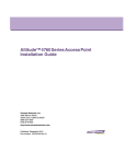
AP-7562 ACCESS POINT
INSTALLATION GUIDE
2
AP-7562 Access Point
Zebra and the Zebra head graphic are registered trademarks of ZIH Corp. The Symbol logo is a registered
trademark of Symbol Technologies, Inc., a Zebra Technologies company.
© 2015 Symbol Technologies, Inc.
Installation Guide
1.0 Introduction . . . . . . . . . . . . . . . . . . . . . . . . . . . . . . . . . . . . . . . . . . . . . . . . . . . . . . 5
1.1 Document Conventions . . . . . . . . . . . . . . . . . . . . . . . . . . . . . . . . . . . . . . . . . . . . 5
1.2 AP-7562 Hardware . . . . . . . . . . . . . . . . . . . . . . . . . . . . . . . . . . . . . . . . . . . . . . . . 6
1.3 AP-7562 Antenna Accessories . . . . . . . . . . . . . . . . . . . . . . . . . . . . . . . . . . . . . . . 6
1.3.1 AP-7562 Dual Band 2.4 GHz / 5 GHz Antennas - US and Canada . . . . . . . . 7
1.3.2 AP-7562 Single Band 2.4 GHz Antennas - US and Canada . . . . . . . . . . . . 7
1.3.3 AP-7562 Single Band 5 GHz Antenna - US and Canada . . . . . . . . . . . . . . . 7
1.3.4 Outdoor Elevation Gain Configuration for US SKUs . . . . . . . . . . . . . . . . . . 8
1.3.5 AP-7562 Dual Band 2.4 GHz / 5 GHz Antennas - EU . . . . . . . . . . . . . . . . . . 8
1.3.6 AP-7562 Single Band 2.4 GHz Antennas - EU . . . . . . . . . . . . . . . . . . . . . . . 8
1.3.7 AP-7562 Single Band 5 GHz Antenna - EU. . . . . . . . . . . . . . . . . . . . . . . . . . 8
1.4 Hardware and Mounting Accessories . . . . . . . . . . . . . . . . . . . . . . . . . . . . . . . . . 9
1.5 AP-7562 Mounting Accessories . . . . . . . . . . . . . . . . . . . . . . . . . . . . . . . . . . . . . . 9
1.6 AP-7562 Weatherized Ethernet Accessory . . . . . . . . . . . . . . . . . . . . . . . . . . . . . 9
1.7 Package Contents . . . . . . . . . . . . . . . . . . . . . . . . . . . . . . . . . . . . . . . . . . . . . . . . 10
1.8 Hardware Installation Guidelines. . . . . . . . . . . . . . . . . . . . . . . . . . . . . . . . . . . . 10
1.8.1 Precautions. . . . . . . . . . . . . . . . . . . . . . . . . . . . . . . . . . . . . . . . . . . . . . . . . 11
1.8.2 Warnings . . . . . . . . . . . . . . . . . . . . . . . . . . . . . . . . . . . . . . . . . . . . . . . . . . 12
1.9 Access Point Placement . . . . . . . . . . . . . . . . . . . . . . . . . . . . . . . . . . . . . . . . . . . 13
1.10 AP-7562 Hardware Overview . . . . . . . . . . . . . . . . . . . . . . . . . . . . . . . . . . . . . . 13
1.10.1 AP-7562 Ports and Connections. . . . . . . . . . . . . . . . . . . . . . . . . . . . . . . . 13
1.10.2 AP-7562 Antenna Connectors . . . . . . . . . . . . . . . . . . . . . . . . . . . . . . . . . 14
1.10.3 AP-7562 Antenna Mouting Guidelines . . . . . . . . . . . . . . . . . . . . . . . . . . 15
1.10.4 AP-7562 Grounding Post . . . . . . . . . . . . . . . . . . . . . . . . . . . . . . . . . . . . . 16
1.11 LED Indicators . . . . . . . . . . . . . . . . . . . . . . . . . . . . . . . . . . . . . . . . . . . . . . . . . . 17
2.0 AP-7562 Hardware Mounting and Installation . . . . . . . . . . . . . . . . . . . . . . . . 18
2.1 Mounting Bracket Kit . . . . . . . . . . . . . . . . . . . . . . . . . . . . . . . . . . . . . . . . . . . . . 19
2.1.1 Extension Arm Kit. . . . . . . . . . . . . . . . . . . . . . . . . . . . . . . . . . . . . . . . . . . . 19
2.2 Pole Mounted Installations . . . . . . . . . . . . . . . . . . . . . . . . . . . . . . . . . . . . . . . . 20
3
4
AP-7562 Access Point
2.2.1 Vertical Pole Mount . . . . . . . . . . . . . . . . . . . . . . . . . . . . . . . . . . . . . . . . . . 21
2.2.2 Wall Mounted Installations . . . . . . . . . . . . . . . . . . . . . . . . . . . . . . . . . . . . 27
2.3 AP-7562 Power Options Using Power over Ethernet . . . . . . . . . . . . . . . . . . . . . 29
3.0 Basic Access Point Configuration . . . . . . . . . . . . . . . . . . . . . . . . . . . . . . . . . . 30
4.0 Specifications . . . . . . . . . . . . . . . . . . . . . . . . . . . . . . . . . . . . . . . . . . . . . . . . . . . 41
4.1 Physical Characteristics . . . . . . . . . . . . . . . . . . . . . . . . . . . . . . . . . . . . . . . . . . . 41
4.2 Environmental Characteristics . . . . . . . . . . . . . . . . . . . . . . . . . . . . . . . . . . . . . . 41
4.3 Power Characteristics . . . . . . . . . . . . . . . . . . . . . . . . . . . . . . . . . . . . . . . . . . . . 42
5.0 Regulatory Information . . . . . . . . . . . . . . . . . . . . . . . . . . . . . . . . . . . . . . . . . . . . 43
5.1 Wireless Country Approvals . . . . . . . . . . . . . . . . . . . . . . . . . . . . . . . . . . . . . . . 43
5.2 Frequency of Operation - FCC and IC . . . . . . . . . . . . . . . . . . . . . . . . . . . . . . . . . 44
5.3 Industry Canada Statement . . . . . . . . . . . . . . . . . . . . . . . . . . . . . . . . . . . . . . . . 44
5.4 Health and Safety Recommendations . . . . . . . . . . . . . . . . . . . . . . . . . . . . . . . . 44
5.4.1 Warnings for the Use of Wireless Devices . . . . . . . . . . . . . . . . . . . . . . . . 44
5.4.2 Potentially Hazardous Atmospheres . . . . . . . . . . . . . . . . . . . . . . . . . . . . . 44
5.5 RF Exposure Guidelines . . . . . . . . . . . . . . . . . . . . . . . . . . . . . . . . . . . . . . . . . . . 45
5.6 Power Supply . . . . . . . . . . . . . . . . . . . . . . . . . . . . . . . . . . . . . . . . . . . . . . . . . . . 45
5.7 Radio Frequency Interference Requirements - FCC . . . . . . . . . . . . . . . . . . . . . . 45
5.7.1 Radio Transmitters (Part 15) . . . . . . . . . . . . . . . . . . . . . . . . . . . . . . . . . . . 47
5.8 Radio Frequency Interference Requirements - Canada . . . . . . . . . . . . . . . . . . . 47
5.9 CE Marking and European Economic Area (EEA) . . . . . . . . . . . . . . . . . . . . . . . . 48
5.10 Statement of Compliance . . . . . . . . . . . . . . . . . . . . . . . . . . . . . . . . . . . . . . . . 48
5.11 Other Countries . . . . . . . . . . . . . . . . . . . . . . . . . . . . . . . . . . . . . . . . . . . . . . . . 48
5.12 Waste Electrical and Electrical Equipment (WEEE) . . . . . . . . . . . . . . . . . . . . . 52
5.13 Turkish WEEE Statement of Compliance . . . . . . . . . . . . . . . . . . . . . . . . . . . . . 53
6.0 Support . . . . . . . . . . . . . . . . . . . . . . . . . . . . . . . . . . . . . . . . . . . . . . . . . . . . . . . . . 54
7.0 Symbol Technologies End-User Software License Agreement . . . . . . . . . 55
8.0 AP-7562 Series ROHS Compliance . . . . . . . . . . . . . . . . . . . . . . . . . . . . . . . . . . 62
Installation Guide
5
1 Introduction
Designed for extending network coverage to outside areas, the AP-7562 brings the latest 802.11ac 3x3:3 Multiple
Input Multiple Output (MIMO) dual radio design together with rugged outdoor performance. The AP-7562 is a
3x3:3 802.11ac Access Point utilizing one 2.4 GHz 802.11n radio and one 5 GHz 802.11ac radio. The AP-7562 is
optimized with WiNG intelligence, extending QoS, security, and mobility services to the Access Point to support
better capacity and performance.
Deployments can be managed using WiNG architecture. WiNG architecture leverages the best aspects of
independent and dependent architectures to create a smart network that meets the connectivity, quality, and
security needs of each user and their applications based on the availability of network resources, including wired
networks.
Once adopted by a WLAN or Integrated Services Controller running WiNG firmware, the AP-7562 is managed as
an Adaptive AP, running the WiNG network management protocol. WiNG networks extend the current
differentiation that Adaptive APs offered to the next level by now having the services and security available at
every point in the network. The traffic flow is optimized to prevent wired congestion. Traffic flows dynamically,
based on user and application, and finds alternate routes to work around any possible network choke points.
Mixed-media application optimization is the hallmark of WiNG 5 networks.
1.1 Document Conventions
The following graphical alerts are used in this document to indicate notable situations:
NOTE
!
Tips, hints, or special requirements that you should take note of.
CAUTION
Care is required. Disregarding a caution can result in data loss or equipment
malfunction.
WARNING! Indicates a condition or procedure that could result in personal injury or equipment
damage.
6
AP-7562 Access Point
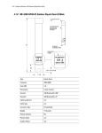
1.2 AP-7562 Hardware
There are currently three AP-7562 Access Points:
Model Part Number
Description
AP-7562-67040-US
AP-7562 Access Point outdoor IP67 dual radio 3x3:3 802.11 a/b/g/n/ac radio SKU: US
AP-7562-67040-EU
AP-7562 Access Point outdoor IP67 dual radio 3x3:3 802.11 a/b/g/n/ac radio SKU: EU
AP-7562-67040-WR
AP-7562 Access Point outdoor IP67 dual radio 3x3:3 802.11 a/b/g/n/ac radio SKU: WR
NOTE
All AP-7562 Access Points ship with one weatherized Ethernet adapter. AP-7562
Access Points do not ship with the Mounting Kit/Antenna and POE injector. These
items must be ordered separately.
1.3 AP-7562 Antenna Accessories
NOTE
Antennas must be ordered separately and are not included with the AP-7562.
The AP-7562 antenna suite includes the following optional antenna accessories. The antennas do not ship with the
AP-7562 Access Points and must be ordered separately.
Installation Guide
7
1.3.1 AP-7562 Dual Band 2.4 GHz / 5 GHz Antennas - US and Canada
Part Number
Antenna Type
2.4 GHz Peak Gain
5.2 GHz Peak Gain
ML-2452-HPAG4A6-01
Dipole
4.0
7.3
ML-2452-HPA6X6-036
Dipole
4.0
7.3
ML-2452-HPA6-01
Dipole
5.3
6.1
ML-2452-PNA5-01R
Panel
5.5
6.0
ML-2452-PNL3M3-1
Polarized Panel
9.7
9.2
1.3.2 AP-7562 Single Band 2.4 GHz Antennas - US and Canada
Part Number
Antenna Type
2.4 GHz Peak Gain
ML-2499-FHPA5-01R
Dipole
5.3
ML-2499-HPA4-01
Dipole
4.5
ML-2499-5PNL-72-N
Panel
6.5
1.3.3 AP-7562 Single Band 5 GHz Antenna - US and Canada
Part Number
ML-5299-HPA5-01
Antenna Type
5.2 GHz Peak Gain
Dipole
5.6
8
AP-7562 Access Point
1.3.4 Outdoor Elevation Gain Configuration for US SKUs
Per FCC requirement, the use of the Access Point on UNII-1 band requires installers to input antenna elevation gain
for dipole antennas during configuration. This information can be found in Zebra antenna guide document at
www.zebra.com/support.
The applicable outdoor antennas on 5GHz band are shown below:
Index
Antenna Type
Part Number
Elevation Gain
1
Dipole
ML-5299-HPA5-01
-2.53
2
Dipole
ML-2452-HPAG4A6-01
5.7
3
Dipole
ML-2452-HPA6X6-036
3.9
4
Dipole
ML-2452-HPA6-01
4.09
1.3.5 AP-7562 Dual Band 2.4 GHz / 5 GHz Antennas - EU
Part Number
Antenna Type
2.4 GHz Peak Gain
5.2 GHz Peak Gain
ML-2452-HPAG5A8-01
Dipole
7.5
8.0
ML-2452-PNA7-01R
Panel
8.0
12.0
ML-2452-PNL3M3-1
Polarized Panel
9.7
9.2
1.3.6 AP-7562 Single Band 2.4 GHz Antennas - EU
Part Number
Antenna Type
2.4 GHz Peak Gain
ML-2499-FHPA9-01R
Dipole
10.5
ML-2499-HPA8-01
Dipole
8.0
1.3.7 AP-7562 Single Band 5 GHz Antenna - EU
Part Number
Antenna Type
5.2 GHz Peak Gain
ML-5299-HPA10-01
Dipole
10.5
ML-5299-HPA5-01
Dipole
5.6
Installation Guide
9
1.4 Hardware and Mounting Accessories
The AP-7562 is a Power over Ethernet (PoE) device. When deployed, the use of an outdoor rated PoE power supply
and mounting bracket may be required. The recommended PoE accessories are listed in the following table:
Part Number
Description
AP-PSBIAS-7161-US
Outdoor IP66 802.3AT gigabit Ethernet power injector, 100-240 VAC US
AP-PSBIAS-7161-WW
Outdoor IP66 802.3AT gigabit Ethernet power injector, 100-240 VAC International
KT-153143-01
Outdoor PoE mounting kit
1.5 AP-7562 Mounting Accessories
The AP-7562 has a flexible three piece mounting kit (KT-147407-01), together with an optional standoff extension
arm (KT-150173-01) for pole mounting.
Part Number
Description
KT-147407-01
Hardware Mounting Kit
KT-150173-01
12 inch extension arm for mounting kit
1.6 AP-7562 Weatherized Ethernet Accessorys
One RJ45 weatherized connector plug is included with each AP-7562 Access Point. If additional plugs are
required, they can be ordered using the part number listed in the following table:
Part Number
KT-153676-01
!
Description
RJ45 weatherized connector plug
CAUTION
When connecting RJ45 cables, ensure that all cables are connected to the Access
Point from the bottom, and include a drip loop to prevent moisture intrusion. Cover
the Ethernet cable with self-healing weatherproofing tape.
Refer to the installation instructions included with the RJ45 weatherized connector plug for proper procedure to
form a drip loop with the cable.
10
AP-7562 Access Point
1.7 Package Contents
Carefully remove all protective packing material around the AP-7562 Access Point and save the container for
storage. Refer to AP-7562 Hardware on page 6 when verifying all AP-7562 hardware has been received.
Record the serial numbers on the shipping cartons and AP-7562 for warranty claims and reference during software
download procedures.
NOTE
Record the serial numbers on the shipping cartons and AP-7562 Access Points for
warranty claims and reference during software download procedures.
When opening the shipping cartons, inspect the equipment for damage. If you find any damaged equipment or any
equipment is missing, contact Support immediately.
Each AP-7562 Access Point (see AP-7562 Hardware on page 6) includes the following parts:
•
•
•
AP-7562 Access Point
Weatherproof RJ45 plug kit
AP-7562 Access Point Installation Guide (this document)
1.8 Hardware Installation Guidelines
!
CAUTION
All device wiring must comply with the National Electric Code (NEC) or regulations
and procedures defined by the regulatory bodies of the country or region where the
devices are being deployed. All local building and structure codes must be
observed.
WARNING! Strictly observe safety precautions and warnings when installing an AP-7562 Access
Point.
Installation Guide
11
1.8.1 Precautions
Before installing an AP-7562 Access Point, verify the following grounding and lightning protection guidelines:
•
•
•
!
•
The installation professional should be familiar with all grounding requirements and regional codes and
ensure the Access Point and mounting asset are properly grounded. The grounding cable for an AP-7562
must be at a minimum a #10 gauge wire cross section. The cable can be attached to the unit using one
of the following methods:
• Loosen the grounding screw, insert the grounding cable into the hole below it, and tighten the screw.
• Loosen the grounding screw, wind the grounding cable around it, and tighten the screw.
• Attach a ring lug to the grounding cable and secure it to the unit using the grounding screw.
To properly attach the grounding cable to the Access Point, refer to AP-7562 Grounding Post on
page 16.
For Ethernet and lightning protection, it is recommended that a commercially available off-the-shelf
Lightning Protection Unit (LPU) be used on all shielded CAT5E Ethernet connections. The LPU should be
rated for outdoor use.
• For the best possible protection, each Access Point requires an LPU be installed adjacent to the Access
Point. If there is a LAN connection to an indoor network, a second LPU is required at the cable entry
point to the building.
CAUTION
Lightning damage is not covered under the conditions of a standard product
warranty. When installed correctly, Lightning Protection Units (LPUs) provide the
best protection from the harmful effects of lightning. Observe all regional and
national codes that apply for lightning protection.
Verify the deployment environment has a continuous temperature range compatible with the operating
temperature range of the device.
12
AP-7562 Access Point
1.8.2 Warnings
•
•
•
•
•
•
•
•
•
•
•
•
•
•
•
•
•
•
•
•
!
!
Read all installation instructions and site survey reports, and verify correct equipment installation before
connecting the Access Point to its power source.
Remove jewelry and watches before installing this equipment.
Verify the unit is grounded before connecting it to the power source.
Verify any device connected to this unit is properly wired and grounded.
Connect all power cords to a properly wired and grounded electrical circuit. Verify the electrical circuits
have appropriate overload protection.
Attach only approved power cords to the device.
Verify the power connector and socket are accessible at all times during the operation of the equipment.
Do not hold any component containing a radio such that it is very close to or touching any exposed parts
of the body, especially the face or eyes, while transmitting.
Do not work with power circuits in dimly lit spaces.
Do not install this equipment or work with its power circuits during thunderstorms or other weather
conditions that could cause a power surge.
Verify there is adequate ventilation around the device, and that ambient temperatures meet equipment
operation specifications.
Avoid contact with overhead power lines.
Take precautions to avoid injury from falling tools and equipment. Crews should wear hard hats in and
around the installation work site.
Be aware of vehicular traffic in and around the installation work site.
Do not operate a portable transmitter near unshielded blasting caps or in an environment where
explosives are present unless the transmitter is especially certified for such use.
Refer to your site survey and network analysis reports to determine specific requirements for each
deployment.
Assign installation responsibility to the appropriate personnel.
Identify and document where all installed components are located.
Identify and prepare Ethernet and console port connections.
Verify cable lengths are within the maximum allowable distances for optimal signal transmission.
CAUTION
The maximum length allowed for PoE cables is 100 meters.
CAUTION
When connecting RJ45 cables, ensure that all cables are connected to the Access
Point from the bottom, and include a drip loop to prevent moisture intrusion.
Installation Guide
13
1.9 Access Point Placement
Observe the following recommended guidelines:
•
•
•
•
•
Identify each piece of the mounting bracket and mounting extension arm hardware and ancillary
hardware.
Mount the device with the black gore vent down.
Mounting height for network devices should not exceed 30 to 35 feet. Mounting height should vary to
accommodate the topography of the deployment area, foliage, and other obstructions.
Devices can be deployed using any of the recommended outdoor deployment procedures.
Line of Sight (LoS) guidelines should be given special consideration when deploying devices.
1.10 AP-7562 Hardware Overview
The AP-7562 is a 3x3:3 802.11ac Access Point utilizing one 2.4 GHz 802.11n radio and one 5 GHz 802.11ac radio.
An AP-7562 must be installed by trained professionals familiar with RF planning and regulatory limits defined by
the regulatory bodies of the country where the devices are being deployed. All common precautions for grounding
and Electrostatic Discharge (ESD) protection should be observed during deployment and installation. AP-7562
Access Points must be installed such that no harmful interference results from device operation.
1.10.1 AP-7562 Ports and Connections
The AP-7562 Access Point has the following port designations:
•
•
•
•
Antenna ports R1-A, B and C, R2-A, B and C
Console port
GE1/POE - LAN port
GE2 - WAN port
14
AP-7562 Access Point
1.10.2 AP-7562 Antenna Connectors
AP-7562 Access Points (AP-7562-67040-US, AP-7562-67040-EU and AP-7562-67040-WR) are configured with six
N type connectors to support two active WLAN data radios.
WARNING! Antenna ports where no antenna is mounted must be properly terminated using an
approved IP67 terminator.
WARNING! All antenna connectors should be covered with weatherproofing tape.
Installation Guide
1.10.3 Antenna Mounting Guidelines
The following are examples of acceptable mounting for dipole antenna deployments:
The following are examples of acceptable mounting methods for panel antenna deployments:
15
16
AP-7562 Access Point
1.10.4 AP-7562 Grounding Post
The grounding post is located on the bottom of the Access Point above the GND symbol.
WARNING! The grounding cable for an AP-7562 must be at a minimum a #10 gauge wire cross
section.
The grounding cable can be attached to the unit using one of the following methods:
•
•
Use a grounding screw to securely attach the grounding cable to the grounding post. Use an 8mm socket
and driver to tighten the grounding screw to 30 inch pounds (lbf-in).
Attach a ring lug to the grounding cable and use a grounding screw to securely attach the ring lug to the
Access Point. Use an 8mm socket and driver to tighten the grounding screw to 30 inch pounds (lbf-in).
Installation Guide
17
1.11 LED Indicators
AP-7562 Access Points have LED activity indicators on the front of the enclosure. The LEDs provide a status display
indicating error conditions, transmission, and network activity for the 2.4 GHz radio (green) and the 5 GHz radio
(amber).
Task
2.4 GHz Activity LED (Green)
5 GHz Activity LED (Amber)
Unconfigured On
Radio
On
Normal
Operation
• If this radio band is enabled:
Blink at 5 second interval
• If this radio band is disabled:
Off
• If there is activity on this band:
Blink interval at 1 time per second
• If this radio band is enabled:
Blink at 5 second interval
• If this radio band is disabled:
Off
• If there is activity on this band:
Blink interval at 1 time per second
Firmware
Update
Off
On
Locate AP
Mode
LEDs blink in an alternating green, red and
amber pattern using an irregular blink rate.
This LED state in no way resembles normal
operating conditions
LEDs blink in an alternating green, red and
amber pattern using an irregular blink rate.
This LED state in no way resembles normal
operating conditions.
18
AP-7562 Access Point
2 AP-7562 Hardware Mounting and Installation
The AP-7562 mounting bracket kit (KT-147407-01) is recommended for most deployments.. When a standoff
distance is required for a pole mounted or wall mounted installation, use the extension arm kit (KT-150173-01).
2.1 Mounting Bracket Kit
The AP-7562 mounting bracket kit (KT-147407-01) includes the Access Point bracket (left), angle adapter bracket
(center), and pole mount bracket (right) sections:
The Access Point bracket and angle adapter bracket can be rotated (plus or minus 15 degrees) and tilted (up to 45
degrees) to orient the unit for optimal positioning.
The following ancillary hardware to assemble the mounting bracket is included in the kit:
Description
Quantity
M6 serrated hex flanged screws
7
1/2 inch hex head nut
2
1/2 inch x 3/4 inch hex head bolt
2
A torque wrench or ratchet with a 10mm adapter, or an adjustable wrench, can be used to assemble the mounting
brackets.
Installation Guide
19
2.1.1 Extension Arm Kit
When mounting an AP-7562 on poles more than 3 inches in diameter, use the extension arm kit (KT-150173-01) to
provide a minimum standoff distance of twelve inches to avoid interference with the antennas.
The extension arm kit can also be used in combination with the any of the brackets from the mounting bracket kit.
20
AP-7562 Access Point
The following ancillary hardware to attach the extension arm to the mounting bracket kit is included in the
extension arm kit:
Description
Quantity
1/2 inch hex head nut
2
1/2 inch x 3/4 inch hex head bolt
2
2.2 Pole Mounted Installations
The mounting hardware kit and extension arm can be used in various combinations to properly install the AP-7562
on a pole. For poles of up to 3 inches in diameter, attach the pole mount bracket of the mounting hardware kit at
the desired position on the pole using band clamps up to 3/4 inch width, or a 1/2 inch x 4 inch wide U-bolt and
nuts. For poles greater than 3 inches in diameter, attach the pole mount bracket using band clamps.
!
CAUTION
Always mount the AP-7562 with the black gore vent facing down.
NOTE
The U-bolt and band clamps are not included in the mounting bracket kit.
NOTE
Use of the extension arm is recommended for installations on poles greater than 3
inches in diameter.
Installation Guide
21
2.2.1 Vertical Pole Mount
Use the following procedure for vertical pole mount installations. The extension arm is recommended when
mounting the Access Point to poles greater than 3 inches is diameter.
For poles up to 3 inches in diameter when using a U-bolt:
1. Thread two 1/2 inch nuts onto the U-bolt.
2. Position the U-bolt on the pole and place the pole mount bracket on the U bolt. Adjust the two 1/2 inch
inner nuts until the pole mount bracket is against the pole and the U-bolt can be secured tightly to the pole
at the desired mounting location.
3. Place the angle adapter bracket on the U-bolt with the open slot connections on the bottom and align it
with the pole mount. Attach with two 1/2 inch nuts. Tighten all nuts to 300 inch pounds (lbf-in).
22
AP-7562 Access Point
4. Position the Access Point bracket so the bottom of the section with the straight (not bevel cut) side is
oriented toward the bottom side of the AP with the gore vent. Using a torque wrench or a ratchet and a
10mm socket, or an adjustable wrench, attach (but don’t tighten) the Access Point bracket to the AP-7562
with the four M6 flange screw.
5. Insert two M6 hex flange screws into the bottom holes on the sides of the Access Point bracket.
Installation Guide
23
6. With the Access Point positioned so the gore vent is facing down, insert the two M6 hex flange screws
in the bottom holes on the sides of the Access Point bracket into the open slot connections on the bottom
of the angle adapter bracket.
7. Rotate the Access Point bracket upward and align the top holes on the sides with the top holes on the
angle adapter bracket. Insert two M6 hex flange screws into the top holes on the angle adapter bracket.
24
AP-7562 Access Point
8. Use a torque wrench or a ratchet and a 10mm socket, or an adjustable wrench, to finish attaching the
Access Point bracket to the angle adapter bracket with the M6 hex flange screws in the open slot
connections and the top holes on the angle adapter bracket. Do not tighten the screws until all rotation
and tilt adjustments are complete.
9. To adjust the position of the Access Point, rotate the Access Point bracket (plus or minus 15 degrees) and
tilt the angle adapter bracket (up to 45 degrees).
10. Tighten all hex flange screws to 60 inch pounds (lbf-in).
For mounting with band clamps:
1. Attach the pole mount bracket at the desired mounting location using band clamps.
2. With the angle adapter bracket positioned so the open connector slots are on the bottom, attach the angle
adapter bracket to the pole mount bracket using two 1/2 inch bolts and nuts. Tighten the nuts to 300 inch
pounds (lbf-in).
3. Position the Access Point bracket so the bottom of the with the straight (not bevel cut) sides is oriented
toward the bottom side of the AP with the gore vent. Using a torque wrench or a ratchet and a 10mm
socket, or an adjustable wrench, attach (but don’t tighten) the Access Point bracket to the AP-7562 with
the four M6 hex flange screws.
4. Insert two M6 hex flange screws into the bottom holes on the sides of the Access Point bracket.
5. With the Access Point positioned so the gore vent is facing down, insert the two M6 hex flange screws
in the bottom holes on the sides of the Access Point bracket into the open slot connections on the bottom
of the angle adapter bracket.
Installation Guide
25
6. Rotate the Access Point bracket upward and align the top holes on the sides with the top holes on the
angle adapter bracket. Insert two M6 hex flange screws into the top holes on the angle adapter bracket.
Use a torque wrench or a ratchet and a 10mm socket, or an adjustable wrench, to finish attaching the
Access Point bracket to the angle adapter bracket with the M6 hex flange screws in the open slot
connections and the top holes on the angle adapter bracket. Do not tighten the screws until all rotation
and tilt adjustments are complete.
7. To adjust the position of the Access Point, rotate the Access Point bracket (plus or minus 15 degrees) and
tilt the angle adapter bracket (up to 45 degrees).
8. Tighten all hex flange screws to 60 inch pounds (lbf-in).
To use the extension arm with the mounting hardware kit:
1. Attach the pole mount at the desired mounting location using a U-bolt or band clamps.
2. Complete the steps for assembling and positioning the mounting bracket sections for poles less than or
greater than 3 inches. See Vertical Pole Mount on page 21.
26
AP-7562 Access Point
3. Using a torque wrench or a ratchet and a 10mm socket, or an adjustable wrench, attach the extension arm
to the Access Point bracket with four M6 hex flange screws. The two oval holes must be positioned on
the short sides of the Access Point. Tighten the hex flange screws to 60 inch pounds (lbf-in) the unit.
4. With the Access Point positioned so the gore vent is facing down, attach the extension arm to the Access
Point bracket with two 1/2 inch bolts and nuts. Tighten the nuts to 300 inch pounds (lbf-in).
Installation Guide
27
2.2.2 Wall Mounted Installations
For wall mounted installations, use only the Access Point bracket and angle adjust bracket if required.
!
CAUTION
Always mount the AP-7562 with the black gore vent facing down.
NOTE
The U-bolt and band clamps are not included in the mounting bracket kit.
NOTE
The lag bolts are not included in the mounting bracket kit.
1. With the open slot connections facing down, attach the angle adjust bracket at the desired mounting
location using four #10/32 lag bolts.
2. Using a torque wrench or a ratchet and a 10mm socket, or an adjustable wrench, attach (but don’t tighten)
the Access Point bracket to the AP-7562 with four M6 hex flange screws and insert two M6 hex flange
screws into the bottom holes on the sides of the Access Point bracket.
28
AP-7562 Access Point
3. With the Access Point positioned so the gore vent is facing down, insert the two M6 hex flange screws
in the bottom holes on the sides of the Access Point bracket into the open slot connections on the bottom
of the angle adapter bracket. Rotate the Access Point bracket upward and align the top holes on the sides
with the top holes on the angle adapter bracket. Insert two M6 hex flange screws into the top holes on
the angle adapter bracket.
4. Use a torque wrench or a ratchet and a 10mm socket, or an adjustable wrench, to finish attaching the
angle adapter bracket to the Access Point bracket with the four M6 hex flange screws in the open slot
connections and the top holes on the angle adapter bracket. Do not tighten the screws until all rotation
and tilt adjustments are complete.
5. To adjust the position of the Access Point, rotate the Access Point bracket (plus or minus 15 degrees) and
tilt the angle adapter bracket (up to 45 degrees).
6. Use a torque wrench or a ratchet and a 10mm socket, or an adjustable wrench, to tighten all screws when
all adjustments are complete.
7. Tighten all hex flange screws to 60 inch pounds (lbf-in).
To use the extension arm with the mounting hardware kit:
1. With the open slot connections facing down, attach the angle adjust bracket at the desired mounting
location using four #10/32 lag bolts.
2. Complete the steps for assembling and positioning the angle adapter bracket and Access Point bracket
sections outlined above. See Vertical Pole Mount on page 21.
3. With the Access Point positioned so the gore vent is facing down, attach the extension arm to the Access
Point bracket with two ½ inch bolts and nuts. Tighten bolts to 300 inch pounds (lbf-in).
Installation Guide
29
2.3 AP-7562 Power Options Using Power over Ethernet
Power over Ethernet (PoE) is the power source for an AP-7562 Access Point. For optimal performance, an AP-7562
can be powered by the following injectors and RFS controllers that support 802.AT PoE.
For installations requiring an outdoor PoE injector, the following options are recommended:
• AP-PSBIAS-7161-US
• AP-PSBIAS-7161-WW
The AP-PSBIAS-7161 is a 1-Port 802.3at PoE Gigabit Ethernet injector. The injector is IP66 rated for outdoor
deployments when used with the weatherproof kit supplied.
There are two power cord options. The AP-PSBIAS-7161-US comes equipped with a cable with a standard three
prong power plug. This plug can be removed by the installer if required when connecting to an AC source. The
AP-PSBIAS-7161-WW comes equipped with a cable with open leads. Mounting kits are not supplied (see
Hardware and Mounting Accessories on page 9 for mounting kit part numbers).
NOTE
Product installation and mounting instructions are provided with the outdoor power
injector.
If located within 100 meters of the controller and a PoE port is available, the AP-7562 Access Point can also be
connected directly to a WLAN or Integrated Services Controller running WiNG 5.6 or higher.
A standard CAT5E cable can be used to provide the connection to the AP-7562. The GE1/POE port on the AP-7562
is where the standard CAT5E cable will connect to the Access Point and use of the weatherproof RJ45 plug kit
that comes with the unit will maintain a weatherproof seal for outdoor installation at the ethernet port.
If a CAT5E cable is used to connect the Access Point to an RFS controller through a building egress, a suitable
lightning protection system should be considered. A professional installer should be consulted to identify an
appropriate system.
30
AP-7562 Access Point
3 Basic Access Point Configuration
Once the Access Point is installed and powered on, complete the following steps to get the device up and running
and access management functions:
1. Attach an Ethernet cable from the Access Point to a controller with an 802.3af compatible power source
to supply power to the AP-7562 (once fully cabled).
If your host system is a DHCP server, an IP address is automatically assigned to the AP-7162 and can be
used for device connection. However, if a DHCP server is not available, you’ll need to derive the IP address
from the AP MAC address. Using this method, the last two bytes of the MAC address become the last two
octets of the IP address. For example:
MAC address - 00:C0:23:00:F0:0A
Zero-Config IP address - 169.254.240.10
To derive the Access Point’s IP address using its MAC address:
a. Open the Windows calculator be selecting Start > All Programs > Accessories > Calculator. This menu
path may vary slightly depending on your version of Windows.
b. With the Calculator displayed, select View > Scientific. Select the Hex radio button.
c. Enter a hex byte of the Access Point’s MAC address. For example, F0.
2. Select the Dec radio button. The calculator converts F0 into 240. Repeat this process for the last Access
Point MAC address octet.Point the Web browser to the Access Point’s IP address. The following login
screen displays:
Installation Guide
31
3. Enter the default username admin in the Username field.
4. Enter the default password admin123 in the Password field.
5. Click the Login button to load the management interface.
NOTE
When logging in for the first time, you’re prompted to change the
password to enhance device security in subsequent logins.
NOTE
If you get disconnected when running the wizard, you can connect again
with the Access Point’s actual IP address (once obtained) and resume the
wizard.
6. If this is the first time the management interface has been accessed, the Initial Setup Wizard
automatically displays.
The Introduction screen displays the various actions that can be performed using the wizard under the
Function Highlight field.
32
AP-7562 Access Point
Use the Choose One type to Setup the Access Point field options to select the type of wizard to run.
The Typical Setup is the recommended wizard. This wizard uses the default parameters for most of the
configuration parameters and sets up a working network with the least amount of manual configuration.
The Advanced Setup wizard is for administrators who prefer more control over the different
configuration parameters. A few more configuration screens are available for customization when the
Advanced Setup wizard is used.
The first page of the Initial Setup Wizard displays the Navigation Panel and Function Highlights for
the configuration activities comprising the Access Point's initial setup. This page also displays options to
select the typical or advanced mode for the wizard.
The Navigation Panel for the Typical Setup Wizard displays the basic configuration options.
A green checkmark to the left of an item in the Navigation Panel defines the task as having its minimum
required configuration set correctly. A red X defines a task as still requiring at least one parameter be
defined correctly.
Installation Guide
33
7. Select Save/Commit within each page to save the updates made to that page's configuration. Select
Next to proceed to the next page listed in the Navigation Panel without saving your updates.
NOTE
While you can navigate to any page in the navigation panel, you cannot
complete the Initial AP Setup Wizard until each task in the Navigation
Panel has a green checkmark.
For the purposes of this guide, use the Typical Setup (Recommended) option to simplify the process of
getting the Access Point up and running quickly with a minimum number of changes to the Access Point’s
default configuration.
For information on using the Access Point’s Advanced Setup option, refer to the WiNG Access Point
System Reference Guide to familiarize yourself with the feature set supported by the WiNG operating
system. The guide is available at www.zebra.com/support.
To configure the Access Point using the Typical Setup Wizard:
8. Select Typical Setup from the Choose One type to Setup the Access Point field on the Initial Setup
Wizard.
9. The Typical Setup Wizard displays the Access Point Settings screen to define the Access Point's
Standalone versus Virtual Controller AP functionality. This screen also enables selection of the country of
operation for the Access Point.
34
AP-7562 Access Point
10. Select an Access Point Type from the following options:
• Virtual Controller AP - When more than one Access Point is deployed, a single Access Point can
function as a Virtual Controller AP. Up to 24 Access Points can be connected to, and managed by,
a single Virtual Controller AP of the same Access Point type. These connected Access Points must
be the same type as the Virtual Controller AP.
• Standalone AP - Select this option to deploy this Access Point as an autonomous fat Access Point.
A Standalone AP isn't managed by a Virtual Controller AP, or adopted by a controller.
NOTE If wanting to adopt the Access Point to a controller or service platform,
use the controller or service platform’s resident UI to connect to the
Access Point, provision its configuration and administrate the Access
Point’s configuration.
NOTE If designating the Access Point as a Standalone AP, it is recommended
the Access Point’s UI be used exclusively to define its device
configuration, and not the CLI. The CLI provides the ability to define more
than one profile and the UI does not. Consequently, the two interfaces
cannot be used collectively to manage profiles without an administrator
encountering problems.
11. Select the Country Code of the country where the Access Point is deployed. Selecting a proper country
is a critical task while configuring the Access Point, as it defines the correct channels of operation and
ensures compliance to the regulations of the selected country. This field is only available for the Typical
Setup Wizard.
NOTE
Access Point AP-7562-67040-US lists US as the only option in the list of country codes.
12. Select Next to set the Access Point’s network mode.
Installation Guide
35
13. The Typical Setup Wizard displays the Network Topology screen to define how the Access Point handles
network traffic.
14. Select an Access Point Mode from the available options.
• Router Mode -In Router Mode, the Access Point routes traffic between the local network (LAN) and
the Internet or external network (WAN). Router mode is recommended in a deployment supported by
just a single Access Point.
• Bridge Mode - In Bridge Mode, the Access Point depends on an external router for routing LAN and
WAN traffic. Routing is generally used on one device, whereas bridging is typically used in a larger
density network. Select Bridge Mode when deploying this Access Point with numerous peer Access
Points supporting clients on both the 2.4GHz and 5GHz radio bands.
NOTE When Bridge Mode is selected, WAN configuration cannot be performed
and the Typical Setup Wizard does not display the WAN configuration
screen.
36
AP-7562 Access Point
15. Select Next. The Typical Setup Wizard displays the LAN Configuration screen to set the Access Point's
LAN interface configuration.
16. Set the following DHCP and Static IP Address/Subnet information for the LAN interface:
• Use DHCP - Select the checkbox to enable an automatic network address configuration using the
Access Point’s DHCP server.
• Static IP Address/Subnet - Enter an IP Address and a subnet for the Access Point's LAN interface. If
Use DHCP is selected, this field is not available. When selecting this option, define the following DHCP
Server and Domain Name Server (DNS) resources, as those fields will become enabled on the bottom
portion of the screen.
• Use on-board DHCP server to assign IP addresses to wireless clients - Select the checkbox to
enable the Access Point’s DHCP server to provide IP and DNS information to clients on the LAN
interface.
• Range - Enter a starting and ending IP Address range for client assignments on the LAN interface.
Avoid assigning IP addresses from x.x.x.1 - x.x.x.10 and x.x.x.255, as they are often reserved for
standard network services. This is a required parameter.
• Default Gateway - Define a default gateway address for use with the default gateway. This is a
required parameter.
Installation Guide
37
• DNS Forwarding - Select this option to allow a DNS server to translate domain names into IP
addresses. If this option is not selected, a primary and secondary DNS resource must be specified.
DNS forwarding is useful when a request for a domain name is made but the DNS server, responsible
for converting the name into its corresponding IP address, cannot locate the matching IP address.
• Primary DNS - Enter an IP Address for the main Domain Name Server providing DNS services for
the Access Point's LAN interface.
• Secondary DNS - Enter an IP Address for the backup Domain Name Server providing DNS services
for the Access Point's LAN interface.
17. Select Next. The Typical Setup Wizard displays the Wireless LAN Setup screen to set the Access
Point’s Wireless LAN interface configuration.
18. Set the following WLAN1 Configuration parameters:
• SSID - Configure the SSID for the WLAN.
• WLAN Type - Configure the encryption and authentication to use with this WLAN.
• No Authentication and No Encryption - Configures a network without any authentication. This
option also configures the network without encryption. This means that any data transmitted
through the network is in plain text. Any device between end points can see the information
transmitted. This is the least secure of all network configurations.
• Captive Portal Authentication and No Encryption - Configures a network that uses a RADIUS server
to authenticate users before allowing them on to the network. Once on the network, no encryption
is used for the data being transmitted through the network. Select this option to use a Web page
(either internally or externally hosted) to authenticate users before access is granted to the
network.
• PSK authentication, WPA2 encryption - Configures a network that uses PSK authentication and
WPA2 encryption. Select this option to implement a pre-shared key that must be correctly shared
between the Access Point and requesting clients using this WLAN.
38
AP-7562 Access Point
19. Select Next. The Typical Setup Wizard displays the RADIUS Server Configuration screen if required.
Otherwise, the Typical Setup Wizard displays the Summary and Commit screen.
20. Use the Radius Server Configuration screen to configure the users for the onboard RADIUS server. Use
the screen to add, modify and remove RADIUS users.
Installation Guide
39
21. Select Add User to display the dialog to enter user information to add to the RADIUS server user
database.
22. Enter the following user information:
• Username - Provide a user name used to authenticate the user.
• Password - Provide a password used to authenticate the user.
• Confirm Password - Confirm the password by entering the same password as entered in the Password
field.
• Description - Provide a description to identify the user created in the RADIUS server database.
23. To create the entry in the RADIUS server database and add another user, select Create. To create the entry
in the RADIUS server database and close the Add User dialog, select Create & Close.
24. Select Modify User on the RADIUS Server Configuration screen to modify information for an existing user
from the RADIUS database. Highlight the user entry then select Modify User.
NOTE The Username cannot be modified with this dialog.
25. Select Delete User on the RADIUS Server Configuration screen to remove information for an existing
user from the RADIUS database. Highlight the user entry and select Delete User.
26. Select Confirm on the dialog displayed. The entry for the user is removed from the RADIUS database.
27. To dismiss the dialog without adding, modifying or removing entries in the RADIUS server database, select
Cancel.
40
AP-7562 Access Point
28. Select Next. The Typical Setup Wizard displays the Summary and Commit screen to summarize the
screens (pages) and settings updated using the Typical Setup Wizard.
No user intervention or additional settings are required. Its an additional means of validating the Access
Point’s updated configuration before it’s deployed. However, if a screen displays settings not intended as
part of the initial configuration, then any screen can be selected again from within the Navigation Panel
and its settings modified accordingly.
29. If the configuration displays as intended, select Save/Commit to implement these settings to the Access
Point’s configuration. If additional changes are warranted based on the summary, either select the target
page from the Navigational Panel, or use the Back and Next buttons to scroll to the target screen.
Installation Guide
41
4 Specifications
4.1 Physical Characteristics
Dimensions
9.0 in. L x 10.0 in. W x 2.6 in. H
22.8 cm L x 25.4 cm W x 6.6 cm H
Weight (Unit)
5.6lbs / 2.54 Kg
Housing
Outdoor IP67 rated, die-cast aluminum, corrosion resistant enclosure, salt, fog, rust per
ASTM B117
LED activity indication
2 top mounted LEDs
Uplink
2 ports (GE1/GE2) auto-sensing 10/100/1000BaseT Ethernet; 802.3at on GE1 LAN port
Antenna Connectors
6 N-Type console ports
Console Port
Outdoor rated RJ45 console port
Multi Band Security Sensor
Outdoor 24x7 Wireless Intrusion Prevention System (WIPS)
4.2 Environmental Characteristics
Operating Temperature
-22° F to 140° F/-30° C to 60° C
Storage Temperature
-40° F to 140° F/-40° C to 60° C
Operating Humidity
5 to 95% RH non-condensing
IP Sealing
IP 67
Operating Altitude
8,000 ft. at 12 °C
Storage Altitude
30,000 ft. at 28 °C
Wind Rating
150 mph
Electrostatic Discharge
15kV air, 8kV contact
Operational Shock
IEC60721-3-4, Class 4M3, MIL STD 810F
Operational Vibration
IEC60721-3-4, Class 4M3
42
AP-7562 Access Point
4.3 Power Characteristics
Operating Voltage
36-57 VDC
Operating Current
375mA at 48V in 802.3at mode
Integrated PoE
802.3af, 802.3at
Installation Guide
43
5 Regulatory Information
This device is approved under Zebra Technologies Corporation.
All Zebra devices are designed to be compliant with rules and regulations in locations they are sold and will be
labeled as required.
Local language translations are available at the following website:
www.zebra.com/support
Any changes or modifications to Zebra equipment, not expressly approved by Zebra Technologies, could void the
user's authority to operate the equipment.
Zebra devices are professionally installed, the Radio Frequency Output Power will not exceed the maximum
allowable limit for the country of operation.
Antennas: Use only the supplied or an approved replacement antennas. Unauthorized antennas, modifications, or
attachments could cause damage and may violate regulations.
5.1 Wireless Country Approvals
Regulatory markings are applied to the device signifying the radio(s) are approved for use in the following
countries: United States, Canada, Australia, and Europe.
Please refer to the Declaration of Conformity (DoC) for details of other country markings. This is available at:
www.zebra.com/doc.
Note: Europe includes, Austria, Belgium, Bulgaria, Czech Republic, Cyprus, Denmark, Estonia, Finland, France,
Germany, Greece, Hungary, Iceland, Ireland, Italy, Latvia, Liechtenstein, Lithuania, Luxembourg, Malta,
Netherlands, Norway, Poland, Portugal, Romania, Slovak Republic, Slovenia, Spain, Sweden, Switzerland and the
United Kingdom.
Operation of the device without regulatory approval is illegal.
Country Selection
Select only the country in which you are using the device. Any other selection will make the operation of this
device illegal.
44
AP-7562 Access Point
5.2 Frequency of Operation - FCC and IC
2.4 GHz Only
The available channels for 802.11bg operation in the US are Channels 1 to 11. The range of channels is limited by
firmware.
NOTE The EIRP for all outdoor antennas used in the 5.15 - 5.25 GHz band should
not exceed a maximum 125 mW ERIP (21dBm) at any elevation angle
above 30 degrees (21dBm).
5.3 Industry Canada Statement
Caution: The device for the band 5150-5250 MHz is only for indoor usage to reduce potential for harmful
interference to co-Channel mobile satellite systems. High power radars are allocated as primary users (meaning
they have priority) of 5250-5350 MHz and 5650-5850 MHz and these radars could cause interference and/or
damage to LE-LAN devices.
Avertissement: Le dispositive fonctionnant dans la bande 5150-5250 MHz est réservé uniquement pour une
utilisation à l'intérieur afin de réduire les risques de brouillage préjudiciable aux systèmes de satellites mobiles
utilisant les mêmes canaux.
Les utilisateurs de radars de haute puissance sont désignés utilisateurs principaux (c.-à-d., qu'ils ont la priorité)
pour les bands 5250-5350 MHz et 5650-5850 MHz et que ces radars pourraient causer du brouillage et/ou des
dommages aux dispositifs LAN-EL
5.4 Health and Safety Recommendations
5.4.1 Warnings for the Use of Wireless Devices
Please observe all warning notices with regard to the usage of wireless devices.
5.4.2 Potentially Hazardous Atmospheres
Wireless devices transmit radio frequency energy and may affect medical electrical equipment. When installed
adjacent to other equipment, it is advised to verify the adjacent equipment is not adversely affected.
Pacemakers
Pacemaker manufacturers recommended that a minimum of 15cm (6 inches) be maintained between a handheld
wireless device and a pacemaker to avoid potential interference with the pacemaker. These recommendations
are consistent with independent research and recommendations by Wireless Technology Research.
Installation Guide
45
Persons with Pacemakers:
1.Should ALWAYS keep the device more than 15cm (6 inches) from their pacemaker when turned ON.
2.Should not carry the device in a breast pocket.
3.Should use the ear furthest from the pacemaker to minimise the potential for interference.
4.If you have any reason to suspect that interference is taking place, turn OFF your device.
Other Medical Devices
Please consult your physician or the manufacturer of the medical device, to determine if the operation of your
wireless product may interfere with the medical device.
5.5 RF Exposure Guidelines
Reduce RF Exposure - Use Properly
Only operate the device in accordance with the instructions supplied.
International
The device complies with internationally recognized standards covering human exposure to electromagnetic fields
from radio devices. For information on "International" human exposure to electromagnet fields refer to the
Declaration of Conformity (DoC) at www.zebra.com/doc.
For further information on the safety of RF energy from wireless devices - see www.zebra.com/support.
Located under Wireless Communications and Health
Europe
Remote and Standalone Antenna Configurations
To comply with EU RF exposure requirements, antennas that are mounted externally at remote locations or
operating near users at stand-alone desktop of similar configurations must operate with a minimum separation
distance of 35 cm from all persons.
46
AP-7562 Access Point
US and Canada
Co-located statement
To comply with FCC RF exposure compliance requirement, the antenna used for this transmitter must not be
co-located or operating in conjunction with any other transmitter/antenna except those already approved in this
filling.
To satisfy US and Canadian RF exposure requirements, a transmitting device must operate with a minimum
separation distance of 35 cm or more from a person's body.
Pour satisfaire aux exigences Américaines et Canadiennes d'exposition aux radiofréquences, un dispositif de
transmission doit fonctionner avec une distance de séparation minimale de 35 cm ou plus de corps d'une
personne.
5.6 Power Supply
This device must be powered from a 802.3af or 802.3at compliant power source which has been certified by the
appropriate agencies, or by a LISTED Type no. PWRS-14000-247R or AP-PSBIAS-2P3-ATR, direct plug-in power
supply, marked Class 2 or LPS (IEC60950-1,SELV). Use of alternative Power Supply will invalidate any approvals
given to this unit and may be dangerous
5.7 Radio Frequency Interference Requirements - FCC
This equipment has been tested and found to comply with the limits for a Class B digital device,
pursuant to Part 15 of the FCC rules. These limits are designed to provide reasonable protection
against harmful interference in a residential installation. This equipment generates, uses and
can radiate radio frequency energy and, if not installed and used in accordance with the
instructions, may cause harmful interference to radio communications. However there is no guarantee that
interference will not occur in a particular installation. If this equipment does cause harmful interference to radio
or television reception, which can be determined by turning the equipment off and on, the user is encouraged to
try to correct the interference by one or more of the following measures:
• Reorient or relocate the receiving antenna
• Increase the separation between the equipment and receiver
• Connect the equipment into an outlet on a circuit different from that to which the receiver is connected.
• Consult the dealer or an experienced radio/TV technician for help.
Installation Guide
47
5.7.1 Radio Transmitters (Part 15)
This device complies with Part 15 of the FCC Rules. Operation is subject to the following two conditions: (1) this
device may not cause harmful interference, and (2) this device must accept any interference received, including
interference that may cause undesired operation.
5.8 Radio Frequency Interference Requirements - Canada
For RLAN Devices:
The use of 5 GHz RLAN's, for use in Canada, have the following restrictions:
• Restricted Band 5.60 - 5.65 GHz
This device complies with RSS 210 of Industry Canada. Operation is subject to the following two conditions: (1)
this device may not cause harmful interference and (2) this device must accept any interference received,
including interference that may cause undesired operation.
Ce dispositif est conforme à la norme CNR-210 d'Industrie Canada applicable aux appareils radio exempts de
licence. Son fonctionnement est sujet aux deux conditions suivantes: (1) le dispositif ne doit pas produire de
brouillage préjudiciable, et (2) ce dispositif doit accepter tout brouillage reçu, y compris un brouillage susceptible
de provoquer un fonctionnement indésirable.
Label Marking: The Term "IC:" before the radio certification only signifies that Industry Canada technical
specifications were met
To reduce potential radio interference to other users, the antenna type and its gain should be so chosen that the
equivalent isotropically radiated power (EIRP) is not more than that permitted for successful communication.
The device could automatically discontinue transmission in case of absence of information to trans-mit, or
operational failure. Note that this is not intended to prohibit transmission of control or signaling information or the
use of repetitive codes where required by the technology.
In compliance with respective local regulatory law, Access Point software provides professional installers the
option to configure the antenna type and antenna gain for approved antennas.
This radio transmitter MODEL: AP-7562 has been approved by Industry Canada to operate with the antenna types
listed below with the maximum permissible gain and required antenna impedance for each antenna type
indicated. Antenna types not included in this list, having a gain greater than the maximum gain indicated for that
type, are strictly prohibited for use with this device.
Le présent émetteur radio MODEL: AP-7562 a été approuvé par Industrie Canada pour fonctionner avec les types
d'antenne énumérés ci-dessous et ayant un gain admissible maximal et l'impédance requise pour chaque type
d'antenne. Les types d'antenne non inclus dans cette liste, ou dont le gain est supérieur au gain maximal indiqué,
sont strictement interdits pour l'exploitation de l'émetteur.
Refer AP-7562 Antenna Accessories on page 6 of this guide for a listing of the 2.4 and 5 GHz antennas
initially approved for use with the AP-7562.
48
AP-7562 Access Point
5.9 CE Marking and European Economic Area (EEA)
The use of 2.4 GHz RLAN’s, for use through the EEA, have the following restrictions:
• Maximum radiated transmit power of 100 mW EIRP in the frequency range 2.400 -2.4835 GHz
• Italy requires a user license for outside usage.
5.10 Statement of Compliance
Zebra hereby declares that this device is in compliance with the essential requirements and other relevant
provisions of Directive 1999/5/EC. A Declaration of Conformity may be obtained from www.zebra.com/doc.
5.11 Other Countries
Australia
Use of 5 GHz RLAN’s in Australia is restricted in the following band: 5.50 – 5.65 GHz.
Brazil (UNWANTED EMISSIONS - ALL PRODUCTS)
Regulatory Declarations for AP-7562 - BRAZIL
For more information consult the website http://www.anatel.gov.br.
Declarações Regulamentares para AP-7562 - Brasil
Nota: A marca de certificação se aplica ao Transceptor, modelo AP-7562. Este equipamento opera em caráter
secundário, isto é, não tem direito a proteção contra interferência prejudicial, mesmo de estações do mesmo tipo,
e não pode causar interferência a sistemas operando em caráter primário. Para maiores informações sobre
ANATEL consulte o site: http://www.anatel.gov.br.
Chile
Este equipo cumple con la Resolución No 403 de 2008, de la Subsecretaria de telecomunicaciones, relativa a
radiaciones electromagnéticas.
China
www.zebra.com/support
http://www.tenaa.com.cn/
Installation Guide
Hong Kong
In accordance with HKTA1039, the band 5.15GHz - 5.35GHz is for indoor operation only.
Mexico
Restrict Frequency Range to: 2.450 – 2.4835 GHz.
La operación de este equipo está sujeta a las siguientes dos condiciones: (1) es posible que este
equipo o dispositivo no cause interferencia perjudicial y (2) este equipo o dispositivo debe aceptar
cualquier interferencia, incluyendo la que pueda causar su operación no deseada.
S. Korea
For a radio equipment using 2400~2483.5MHz or 5725~5825MHz, the following two
expression should be displayed;
49
50
AP-7562 Access Point
Taiwan
「電磁波曝露量 MPE 標準值 1mW/cm2,本產品使用時建議應距離人體:35 cm」。
Installation Guide
Ukraine
Thailand
51
52
AP-7562 Access Point
5.12 Waste Electrical and Electronic Equipment (WEEE)
English: For EU Customers: All products at the end of their life must be returned to Zebra for recycling. For
information on how to return product, please go to: www.zebra.com/weee.
Français: Clients de l'Union Européenne: Tous les produits en fin de cycle de vie doivent être retournés à Zebra
pour recyclage. Pour de plus amples informations sur le retour de produits, consultez: www.zebra.com/weee.
Español: Para clientes en la Unión Europea: todos los productos deberán entregarse a Zebra al final de su ciclo
de vida para que sean reciclados. Si desea más información sobre cómo devolver un producto, visite:
www.zebra.com/weee.
Български: За клиенти от ЕС: След края на полезния им живот всички продукти трябва да се връщат на
Zebra за рециклиране. За информация относно връщането на продукти, моля отидете на адрес:
www.zebra.com/weee.
Deutsch: Für Kunden innerhalb der EU: Alle Produkte müssen am Ende ihrer Lebensdauer zum Recycling an
Zebra zurückgesandt werden. Informationen zur Rücksendung von Produkten finden Sie unter
www.zebra.com/weee.
Italiano: per i clienti dell'UE: tutti i prodotti che sono giunti al termine del rispettivo ciclo di vita devono essere
restituiti a Zebra al fine di consentirne il riciclaggio. Per informazioni sulle modalità di restituzione, visitare il
seguente sito Web: www.zebra.com/weee.
Português: Para clientes da UE: todos os produtos no fim de vida devem ser devolvidos à Zebra para
reciclagem. Para obter informações sobre como devolver o produto, visite: www.zebra.com/weee.
Nederlands: Voor klanten in de EU: alle producten dienen aan het einde van hun levensduur naar Zebra te
worden teruggezonden voor recycling. Raadpleeg www.zebra.com/weee voor meer informatie over het
terugzenden van producten.
Polski: Klienci z obszaru Unii Europejskiej: Produkty wycofane z eksploatacji nale¿y zwróciæ do firmy Zebra w
celu ich utylizacji. Informacje na temat zwrotu produktów znajduj¹ siê na stronie internetowej
www.zebra.com/weee.
Čeština: Pro zákazníky z EU: Všechny produkty je nutné po skonèení jejich životnosti vrátit spoleènosti Zebra
k recyklaci. Informace o zpùsobu vrácení produktu najdete na webové stránce: www.zebra.com/weee.
Eesti: EL klientidele: kõik tooted tuleb nende eluea lõppedes tagastada taaskasutamise eesmärgil Zebra 'ile.
Lisainformatsiooni saamiseks toote tagastamise kohta külastage palun aadressi: www.zebra.com/weee.
Magyar: Az EU-ban vásárlóknak: Minden tönkrement terméket a Zebra vállalathoz kell eljuttatni újrahasznosítás
céljából. A termék visszajuttatásának módjával kapcsolatos tudnivalókért látogasson el a www.zebra.com/weee
weboldalra.
Svenska: För kunder inom EU: Alla produkter som uppnått sin livslängd måste returneras till Zebra för
återvinning. Information om hur du returnerar produkten finns på www.zebra.com/weee.
Suomi: Asiakkaat Euroopan unionin alueella: Kaikki tuotteet on palautettava kierrätettäväksi Zebra-yhtiöön, kun
tuotetta ei enää käytetä. Lisätietoja tuotteen palauttamisesta on osoitteessa www.zebra.com/weee.
Dansk: Til kunder i EU: Alle produkter skal returneres til Zebra til recirkulering, når de er udtjent. Læs
oplysningerne om returnering af produkter på: www.zebra.com/weee.
Ελληνικά: Για πελάτες στην Ε.Ε.: Όλα τα προϊόντα, στο τέλος της διάρκειας ζωής τους, πρέπει να επιστρέφονται
στην Zebra για ανακύκλωση. Για περισσότερες πληροφορίες σχετικά με την επιστροφή ενός προϊόντος,
επισκεφθείτε τη διεύθυνση www.zebra.com/weee στο ∆ιαδίκτυο.
Installation Guide
53
Malti: Għal klijenti fl-UE: il-prodotti kollha li jkunu waslu fl-aħħar tal-ħajja ta' l-użu tagħhom, iridu jiġu rritornati
għand Zebra għar-riċiklaġġ. Għal aktar tagħrif dwar kif għandek tirritorna l-prodott, jekk jogħġbok żur:
www.zebra.com/weee.
Românesc: Pentru clienţii din UE: Toate produsele, la sfârşitul duratei lor de funcţionare, trebuie returnate la Zebra
pentru reciclare. Pentru informaţii despre returnarea produsului, accesaţi: www.zebra.com/weee.
Slovenski: Za kupce v EU: vsi izdelki se morajo po poteku življenjske dobe vrniti podjetju Zebra za reciklažo. Za
informacije o vračilu izdelka obiščite: www.zebra.com/weee.
Slovenčina: Pre zákazníkov z krajín EU: Všetky výrobky musia byť po uplynutí doby ich životnosti vrátené
spoločnosti Zebra na recykláciu. Bližšie informácie o vrátení výrobkov nájdete na: www.zebra.com/weee.
Lietuvių: ES vartotojams: visi gaminiai, pasibaigus jų eksploatacijos laikui, turi būti grąžinti utilizuoti į kompaniją „
Zebra“. Daugiau informacijos, kaip grąžinti gaminį, rasite: www.zebra.com/weee.
Latviešu: ES klientiem: visi produkti pēc to kalpošanas mūža beigām ir jānogādā atpakaļ Zebra otrreizējai
pārstrādei. Lai iegūtu informāciju par produktu nogādāšanu Zebra, lūdzu, skatiet: www.zebra.com/weee.
Türkçe: AB Müşterileri için: Kullanım süresi dolan tüm ürünler geri dönüştürme için Zebra'ya iade edilmelidir.
Ürünlerin nasıl iade edileceği hakkında bilgi için lütfen şu adresi ziyaret edin: www.zebra.com/weee.
5.13 Turkish WEEE Statement of Compliance
54
AP-7562 Access Point
6 Support
If you have a problem with your equipment, contact support for your region.
Contact information is available at: www.zebra.com/support.
When contacting support, please provide the following information:
• Serial number of the unit
• Model number or product name
• Software type and version number
Support responds to calls by e-mail, telephone, or fax within the time limits set forth in support agreements. If you
purchased your product from a business partner, contact that business partner for support.
Customer Support Web Sites
The Support site, located at www.zebra.com/support.
provides information and online assistance including developer tools, software downloads, product manuals and
online repair requests.
Manuals
www.zebra.com/support.
Installation Guide
7
55
Symbol Technologies End-User Software License Agreement
This End-User Software License Agreement ("End-User License Agreement") is between Symbol Technologies Inc.
(herein "Symbol Technologies") and End-User Customer to whom Symbol Technologies' proprietary software or
Symbol Technologies Products containing embedded, pre-loaded, or installed software ("Products") is made
available. This End-User License Agreement contains the terms and conditions of the license Symbol Technologies
is providing to End-User Customer, and End-User Customer's use of the Software and Documentation. By using,
downloading or installing this software, you or the entity that you represent ("End-User Customer") are consenting
to be bound by and are becoming a party to this End-User License Agreement..
1. DEFINITIONS
“Documentation” means product and software documentation that specifies technical and performance
features and capabilities, and the user, operation and training manuals for the Software (including all
physical or electronic media upon which such information is provided).
“Open Source Software” means software with either freely obtainable source code license for
modification, or permission for free distribution.
“Open Source Software License” means the terms or conditions under which the Open Source
Software is licensed.
“Software” (i) means proprietary software in object code format, and adaptations, translations,
decompilations, disassemblies, emulations, or derivative works of such software; (ii) means any
modifications, enhancements, new versions and new releases of the software provided by Symbol
Technologies; and (iii) may contain items of software owned by a third party supplier. The term
“Software” does not include any third party software provided under separate license or third party
software not licensable under the terms of this Agreement. To the extent, if any, that there is a separate
license agreement packaged with, or provided electronically with, a particular Product that becomes
effective on an act of acceptance by the end user, then that agreement supersedes this End-User License
Agreement as to the end use of that particular Product.
2. GRANT OF LICENSE
2.1
Subject to the provisions of this End-User License Agreement, Symbol Technologies grants to End-User
Customer a personal, limited, non-transferable (except as provided in Section 4), and non-exclusive
license under Symbol Technologies’ copyrights and confidential information embodied in the Software to
use the Software, in object code form, and the Documentation solely in connection with End-User
Customer’s use of the Products. This End-User License Agreement does not grant any rights to source
code.
56
2.2
AP-7562 Access Point
If the Software licensed under this End-User License Agreement contains or is derived from Open Source
Software, the terms and conditions governing the use of such Open Source Software are in the Open
Source Software Licenses of the copyright owner and not this End-User License Agreement. If there is a
conflict between the terms and conditions of this End-User License Agreement and the terms and
conditions of the Open Source Software Licenses governing End-User Customer’s use of the Open Source
Software, the terms and conditions of the license grant of the applicable Open Source Software Licenses
will take precedence over the license grants in this End-User License Agreement. If requested by
End-User Customer, Symbol Technologies will use commercially reasonable efforts to: (i) determine
whether any Open source Software is provided under this End-User License Agreement; (ii) identify the
Open Source Software and provide End-User Customer a copy of the applicable Open Source Software
License (or specify where that license may be found); and, (iii) provide End-User Customer a copy of the
Open Source Software source code, without charge, if it is publicly available (although distribution fees
may be applicable).
3. LIMITATIONS ON USE
3.1
End-User Customer may use the Software only for End-User Customer’s internal business purposes and
only in accordance with the Documentation. Any other use of the Software is strictly prohibited and will
be deemed a breach of this End-User License Agreement. Without limiting the general nature of these
restrictions, End-User Customer will not make the Software available for use by third parties on a “time
sharing,” “application service provider,” or “service bureau” basis or for any other similar commercial
rental or sharing arrangement.
3.2
End-User Customer will not, and will not allow or enable any third party to: (i) reverse engineer,
disassemble, peel components, decompile, reprogram or otherwise reduce the Software or any portion to
a human perceptible form or otherwise attempt to recreate the source code; (ii) modify, adapt, create
derivative works of, or merge the Software with other software; (iii) copy, reproduce, distribute, lend, or
lease the Software or Documentation to any third party, grant any sublicense or other rights in the
Software or Documentation to any third party, or take any action that would cause the Software or
Documentation to be placed in the public domain; (iv) remove, or in any way alter or obscure, any
copyright notice or other notice of Symbol Technologies’ proprietary rights; (v) provide, copy, transmit,
disclose, divulge or make the Software or Documentation available to, or permit the use of the Software
by any third party or on any machine except as expressly authorized by this Agreement; or (vi) use, or
permit the use of, the Software in a manner that would result in the production of a copy of the Software
solely by activating a machine containing the Software. End-User Customer may make one copy of
Software to be used solely for archival, back-up, or disaster recovery purposes; provided that End-User
Customer may not operate that copy of the Software at the same time as the original Software is being
Installation Guide
57
operated. End-User Customer may make as many copies of the Documentation as it may reasonably
require for the internal use of the Software.
3.3
Unless otherwise authorized by Symbol Technologies in writing, End-User Customer will not, and will not
enable or allow any third party to: (i) install a licensed copy of the Software on more than one unit of a
Product; or (ii) copy onto or transfer Software installed in one unit of a Product onto another device.
3.4
If End-User Customer is purchasing Products that require a site license, End-User Customer must
purchase a copy of the applicable Software for each site at which End-User Customer uses such
Software. End-User Customer may make one additional copy for each computer owned or controlled by
End-User Customer at each such site. End-User Customer may temporarily use the Software on portable
or laptop computers at other sites. End-User Customer must provide a written list of all sites where
End-User Customer uses or intends to use the Software.
4. TRANSFERS
4.1
End-User Customer will not transfer the Software or Documentation to any third party without Symbol
Technologies’ prior written consent. Symbol Technologies’ consent may be withheld at its discretion and
may be conditioned upon transferee paying all applicable license fees and agreeing to be bound by this
End-User License Agreement.
5. OWNERSHIP AND TITLE
5.1
Symbol Technologies, its licensors, and its suppliers retain all of their proprietary rights in any form in
and to the Software and Documentation, including, but not limited to, all rights in patents, patent
applications, inventions, copyrights, trademarks, trade secrets, trade names, and other proprietary rights
in or relating to the Software and Documentation. No rights are granted to End-User Customer under this
Agreement by implication, estoppel or otherwise, except for those rights which are expressly granted to
End-User Customer in this End-User License Agreement. All intellectual property developed, originated,
or prepared by Symbol Technologies in connection with providing the Software, Products, Documentation
or related services remains vested exclusively in Symbol Technologies, and End-User Customer will not
have any shared development or other intellectual property rights.
58
AP-7562 Access Point
6. CONFIDENTIALITY
6.1
End-User Customer acknowledges that the Software contains valuable proprietary information and trade
secrets and that unauthorized dissemination, distribution, modification, reverse engineering,
disassembly or other improper use of the Software will result in irreparable harm to Symbol
Technologies for which monetary damages would be inadequate. Accordingly, End-User Customer will
limit access to the Software to those of its employees and agents who need to use the Software for
End-User Customer’s internal business
7. MAINTENANCE AND SUPPORT
7.1
No maintenance or support is provided under this End-User License Agreement. Maintenance or support,
if available, will be provided under a separate Software maintenance and support agreement.
8. LIMITED WARRANTY AND LIMITATION OF LIABILITY
8.1
Unless otherwise specified in the applicable warranty statement, the Documentation or in any other
media at the time of shipment of the Software by Symbol Technologies, and for the warranty period
specified therein, for the first 120 days after initial shipment of the Software to the End-User Customer,
Symbol Technologies warrants that the Software, when installed and/or used properly, will be free from
reproducible defects that materially vary from its published specifications. Symbol Technologies does
not warrant that End-User Customer’s use of the Software or the Products will be uninterrupted or
error-free or that the Software or the Products will meet End-User Customer’s particular requirements.
8.2
SYMBOL TECHNOLOGIES’ TOTAL LIABILITY, AND END-USER CUSTOMER’S SOLE REMEDY, FOR ANY
BREACH OF THIS WARRANTY WILL BE LIMITED TO, AT SYMBOL TECHNOLOGIES’ OPTION, REPAIR OR
REPLACEMENT OF THE SOFTWARE OR PAYMENT OF END-USER CUSTOMER’S ACTUAL DAMAGES UP
TO THE AMOUNT PAID TO SYMBOL TECHNOLOGIES FOR THE SOFTWARE OR THE INDIVIDUAL
PRODUCT IN WHICH THE SOFTWARE IS EMBEDDED OR FOR WHICH IT WAS PROVIDED. THIS
WARRANTY EXTENDS ONLY TO THE FIRST END-USER CUSTOMER; SUBSEQUENT TRANSFEREES MUST
ACCEPT THE SOFTWARE “AS IS” AND WITH NO WARRANTIES OF ANY KIND. SYMBOL
TECHNOLOGIES DISCLAIMS ALL OTHER WARRANTIES, EXPRESS OR IMPLIED, INCLUDING THE IMPLIED
WARRANTIES OF MERCHANTABILITY, NON-INFRINGEMENT, AND FITNESS FOR A PARTICULAR
PURPOSE.
8.3
IN NO EVENT WILL SYMBOL TECHNOLOGIES BE LIABLE FOR SPECIAL, INCIDENTAL OR
CONSEQUENTIAL DAMAGES, INCLUDING, BUT NOT LIMITED TO, LOSS OF USE, TIME OR DATA,
INCONVENIENCE, COMMERCIAL LOSS, LOST PROFITS, OR SAVINGS, TO THE FULL EXTENT SUCH MAY
Installation Guide
59
BE DISCLAIMED BY LAW, EVEN IF ADVISED OF THE POSSIBILITY OF SUCH DAMAGES. THE
LIMITATIONS IN THIS PARAGRAPH WILL APPLY NOTWITHSTANDING ANY FAILURE OF ESSENTIAL
PURPOSE OF ANY LIMITED REMEDY.
9. TERM AND TERMINATION
9.1
Any use of the Software, including but not limited to use on the Products, will constitute End-User
Customer’s agreement to this End-User License Agreement. End-User Customer’s right to use the
Software will continue for the life of the Products with which or for which the Software and
Documentation have been provided by Symbol Technologies, unless End-User Customer breaches this
End-User License Agreement, in which case this End-User License Agreement and End-User Customer’s
right to use the Software and Documentation may be terminated immediately by Symbol Technologies. In
addition, if Symbol Technologies reasonably believes that End-User Customer intends to breach this
End-User License Agreement Symbol Technologies may, by notice to End-User Customer, terminate
End-User Customer’s right to use the Software.
9.2
Upon termination, Symbol Technologies will be entitled to immediate injunctive relief without proving
damages and, unless End-User Customer is a sovereign government entity, Symbol Technologies will
have the right to repossess all copies of the Software in End-User Customer’s possession. Within thirty
(30) days after termination of End-User Customer’s right to use the Software, End-User Customer must
certify in writing to Symbol Technologies that all copies of such Software have been returned to Symbol
Technologies or destroyed.
10. UNITED STATES GOVERNMENT LICENSING PROVISIONS
10.1
This Section applies if End-User Customer is the United States Government or a United States
Government agency. End-User Customer’s use, duplication or disclosure of the Software and
Documentation under Symbol Technologies’ copyrights or trade secret rights is subject to the restrictions
set forth in subparagraphs (c)(1) and (2) of the Commercial Computer Software-Restricted Rights clause
at FAR 52.227-19 (JUNE 1987), if applicable, unless they are being provided to the Department of
Defense. If the Software and Documentation are being provided to the Department of Defense, End-User
Customer’s use, duplication, or disclosure of the Software and Documentation is subject to the restricted
rights set forth in subparagraph (c)(1)(ii) of the Rights in Technical Data and Computer Software clause at
DFARS 252.227-7013 (OCT 1988), if applicable. The Software and Documentation may or may not
include a Restricted Rights notice, or other notice referring to this End-User License Agreement. The
provisions of this End-User License Agreement will continue to apply, but only to the extent that they are
60
AP-7562 Access Point
consistent with the rights provided to the End-User Customer under the provisions of the FAR and DFARS
mentioned above, as applicable to the particular procuring agency and procurement transaction.
11. GENERAL
11.1
Copyright Notices. The existence of a copyright notice on the Software will not be construed as an
admission or presumption that public disclosure of the Software or any trade secrets associated with the
Software has occurred.
11.2
Compliance with Laws. End-User Customer acknowledges that the Software is subject to the laws and
regulations of the United States and End-User Customer will comply with all applicable laws and
regulations, including export laws and regulations of the United States. End-User Customer will not,
without the prior authorization of Symbol Technologies and the appropriate governmental authority of
the United States, in any form export or re-export, sell or resell, ship or reship, or divert, through direct or
indirect means, any item or technical data or direct of indirect products sold or otherwise furnished to
any person within any territory for which the United States Government or any of its agencies at the time
of the action, requires an export license or other governmental approval. Violation of this provision is a
material breach of this Agreement.
11.3
Third Party Beneficiaries. This End-User License Agreement is entered into solely for the benefit of
Symbol Technologies and End-User Customer. No third party has the right to make any claim or assert
any right under this Agreement, and no third party is deemed a beneficiary of this End-User License
Agreement. Notwithstanding the foregoing, any licensor or supplier of third party software included in
the Software will be a direct and intended third party beneficiary of this End-User License Agreement.
11.4
Waiver. No waiver of a right or remedy of a Party will constitute a waiver of another right or remedy of
that Party.
11.5
Assignments. Symbol Technologies may assign any of its rights or sub-contract any of its obligations
under this End-User License Agreement or encumber or sell any of its rights in any Software, without
prior notice to or consent of End-User Customer.
11.6
Causes of Action. End-User Customer must bring any action under this End-User License Agreement
within one year after the cause of action arises except that warranty claims must be brought within the
applicable warranty period.
11.7
Entire Agreement and Amendment. This End-User License Agreement contains the parties’ entire
agreement regarding End-User Customer’s use of the Software and may be amended only in a writing
signed by both parties, except that Symbol Technologies may modify this End-User License Agreement as
necessary to comply with applicable laws and regulations.
Installation Guide
61
11.8
Governing Law. This End-User License Agreement is governed by the laws of the the State of Delaware
in the United States to the extent that they apply and otherwise by the internal substantive laws of the
country to which the Software is shipped if End-User Customer is a sovereign governmental entity. The
terms of the U.N. Convention on Contracts for the International Sale of Goods do not apply. In the event
that the Uniform Computer information Transaction Act, any version of this Act, or a substantially similar
law (collectively “UCITA”) becomes applicable to a Party’s performance under this Agreement, UCITA
does not govern any aspect of this End-User License Agreement or any license granted under this
End-User License Agreement, or any of the parties’ rights or obligations under this End-User License
Agreement. The governing law will be that in effect prior to the applicability of UCITA.
11.8
Dispute Resolution. Unless End-User Customer is a sovereign governmental entity, any dispute arising
from or in connection with this End-User License Agreement shall be submitted to the sole and exclusive
forum of the state and federal courts sitting in New Castle County, Delaware (the "Delaware Courts"),
and each Party irrevocably submits to the jurisdiction of the Delaware Courts for the litigation of such
disputes. Each Party hereby irrevocably waives, and agrees not to assert in any suit, action or proceeding
brought in the Delaware Courts, any claim or defense that the Party is not subject to the jurisdiction of
the Delaware Courts, that the Delaware Courts are an inconvenient forum, or that the Delaware Courts
are an improper venue.
62
AP-7562 Access Point
8 AP-7562 Series ROHS Compliance
本表格依据 SJ/T 11364 的规定编制。
O:表示该有害物质在该部件所有均质材料中的含量均在 GB/T 26572 规定的限量 要求以下。
X:表示该有害物质至少在该部件的某一均质材料中的含量超出GB/T 26572 规定 的限量要求。(企业可在此处,根
据实际情况对上表中打“×”的技术原因进 行进一步说明。)
This table was created to comply with China RoHS requirements.
Installation Guide
63
Zebra Technologies Corporation
Lincolnshire, IL 60069 USA
Zebra and the Zebra head graphic are registered trademarks of ZIH Corp. The Symbol logo is a registered trademark of
Symbol Technologies, Inc., a Zebra Technologies company.
© 2015 Symbol Technologies, Inc.
MN001745A01 Revision A April 2015

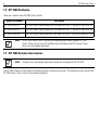
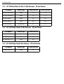
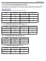
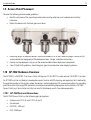
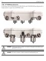
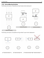
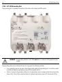
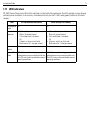
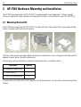

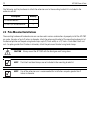


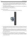
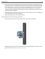

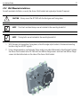


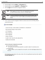


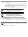


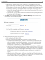
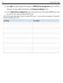


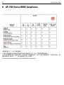


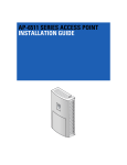

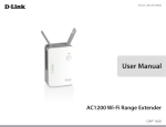
![TC55 Regulatory Guide [English] (P/N MN000016A03 Rev. A)](http://vs1.manualzilla.com/store/data/006084957_1-919751c600ce55e2e6481c06e14d0eb9-150x150.png)