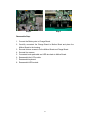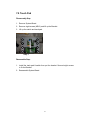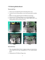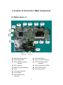
1
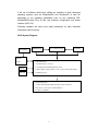
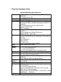
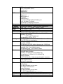
1 General system Description ........................................................................................5 1.1 System Overview .............................................................................................5 1.2 System Hardware Parts ....................................................................................7 1.3 Major Component Introduction .......................................................................9 1.3.1 CPU Module .........................................................................................9 1.3.2 System frequency ICS950810...............................................................9 1.3.3 Intel 855-GM GMCH IGUI 3D Graphic DDR/SDR Chipset.............10 1.3.4 Memory System.................................................................................. 11 1.3.5 Display ................................................................................................ 11 1.3.6 HUB Interface for ICH4 .....................................................................14 1.3.7 I/O Controller Hub: INTEL 82801DBM ............................................14 1.3.9 Keyboard controller Hitachi H8/3437 ................................................17 1.3.10 Fax/Modem module ..........................................................................18 1.3.11 FAST ETHERNET CONTROLLER integrated ICH-4M ................18 1.3.12 PCMCIA controller_ ENE CB1410 + ENE CP2211 ........................19 1.3.13 AC”97 Code ALC202 .......................................................................19 1.3.14 Thermal sensor_ ADM1021A...........................................................20 2 Motherboard Function Description...........................................................................21 2.1 Hot Key Function...........................................................................................21 2.2 Power on/off/suspend/resume button.............................................................21 2.3 Cover Switch..................................................................................................22 2.4 LED Indicators...............................................................................................22 2.5 Battery status..................................................................................................23 2.6 CMOS Battery ...............................................................................................23 2.7 I/O Port...........................................................................................................23 3 Peripheral ..................................................................................................................26 3.1 LCD PANEL ..................................................................................................26 3.2 HDD...............................................................................................................26 3.3 Keyboard........................................................................................................26 3.4 Track Pad Synaptic ........................................................................................26 3.5 Memory..........................................................................................................27 3.6 Modem MDC .................................................................................................27 4 Power Management ..................................................................................................28 4.1 System Management Mode............................................................................28 4.2 Battery Life ....................................................................................................29 4.3 Other power management functions ..............................................................29 5 Connector and Switch Definition..............................................................................30 2 6 System View .............................................................................................................38 6-1 Front View .....................................................................................................38 6-2 Bottom View..................................................................................................38 6-3 Left-Side View...............................................................................................39 6-4 Right-Side View ............................................................................................39 6-5 Rear View ......................................................................................................40 6-6 Top-open View...............................................................................................40 6-7 Docking Module Front View .........................................................................41 6-8 Docking Module Left-Side View...................................................................41 6-9 Docking Module Right-Side View ................................................................42 6-10 Docking Module Rear View ........................................................................42 7 System Disassembly .................................................................................................43 7-1 Battery Pack...................................................................................................43 7-2 Bottom Housing.............................................................................................44 7-3 Modem Board ................................................................................................45 7-4 Memory .........................................................................................................46 7-5 HDD Module .................................................................................................47 7-6 Keyboard .......................................................................................................48 7-7 LCD Panel .....................................................................................................50 7-8 System Board.................................................................................................51 7-9 Touch Pad ......................................................................................................53 7-10 Docking Mother Board................................................................................54 8 Location of Connectors / Major Components...........................................................56 8-1 Mother Board –A...........................................................................................56 8-2 Mother Board –B ...........................................................................................57 8-3 D/D Board-A .................................................................................................58 8-4 D/ D Board-B.................................................................................................58 8-5 Docking Main Board-A .................................................................................59 8-6 Docking Main Board-B .................................................................................60 9 Trouble Shooting.......................................................................................................61 9-1 No Power .......................................................................................................63 9-2 Battery Can Not Be Charged .........................................................................64 9-3 No display......................................................................................................65 9-4 LCD No Display or Picture Abnormal ..........................................................66 9-5 External Monitor No Display or Color Abnormal.........................................67 9-6 Memory Test Error ........................................................................................68 9-7 Keyboard and Touch –pad Test Error ............................................................69 9-8 System SIO Test Error ...................................................................................70 3 9-9 Hard Drive Test Error ....................................................................................71 9-10 System USB Port Test Error ........................................................................72 9-11 System Audio Failure ..................................................................................73 9-12 PC-Card Socket Failure ...............................................................................74 10 System Exploded views & Circuit Diagram...........................................................75 4 1 General system Description 1.1 System Overview The LightNote W130 is a rugged and high portability industrial computer. The W130 also can connect with a docking to the capability of FLOPPY and CD-ROM and I/O device. The W130 model will support Intel Centrino mobile technology with Pentium-M Processors LV 1.1G, 1.2G with Micro-FCBGA, 12W in TDP and 1Mb L2 Cache. This system is based on PCI architecture, which have standard hardware peripheral interface. The power management complies with Advanced Configuration and Power Interface (ACPI 2.0). It also provides easy configuration through CMOS setup, which is built in system BIOS software and can be pop-up by pressing F2 at system start up or warm reset. System also provides icon LEDs to display system status, such as Power indicator, HDD/CDROM, NUM LOCK, CAP LOCK, SCROLL LOCK, SUSPEND MODE and Battery charging status. It also one USB port. The memory subsystem supports One JEDEC-standard 200-pin, small-outline, dual in-line memory module (SODIMM), support PC2100 and up to 1GB DDR SDRAM. The W130 includes the 855GM chipset components GMCH and the ICH4-M. The Accelerated Hub Architecture interface (the chipset component interconnect) is designed into the chipset to provide an efficient, high bandwidth, communication channel between the GMCH and the ICH4-M. The GMCH component contains a processor system bus (PSB) controller, a graphics controller, and a memory controller, while providing an LVDS interface and two DVO ports. The ICH4-M component integrates USB host controllers (supporting the USB 1.1 and USB 2.0 specification), an Ultra ATA 100/66/33 controller, a LAN controller, and an AC’97 digital controller, while providing interfaces for PCI and LPC devices,. To provide for the increasing number of multimedia applications, the AC97 CODEC ALC201 is integrated onto the motherboard. 5 A full set of software drivers and utilities are available to allow advanced operating systems such as Windows2000 and WindowsXP to take full advantage of the hardware capabilities such as bus mastering IDE, Windows2000-ready Plug & Play, and Advance configuration and power interface (ACPI 2.0). Following chapters will have more detail description for each individual sub-systems and functions. W130 System Diagram: Primary Battery Touch Screen 12.1” LCD/Touch Screen Inverter BD D/D BD 1:DC IN W130 Mother Board 1:Intel Pentium-M LV 1.1G/1.2G Keyboard 2:One 200pin DDR SO-DIMM Socket (max: 1GB) 3:USB*2, RS232*1 (COM1), Modem *1 (RJ-11), LAN*1 (RJ-45),VGA*1(DB15) Trace PAD 4:PCMCIA*1(Type II) W1300 Docking Board 1: USB*2, RS232*2(COM1.COM2), PIO PORT*1,PS2*1,CRT OUT*1 2: MIC IN Con.*1,Line Out Con.*1,Mono Speaker*1 3: FLOPPY*1,CD-ROM*1 6 1.2 System Hardware Parts Internal Marketing Specifications Intel Pentium M Processor LV1.1GHz in µ-FCBGA package FSB 400MHz CPU Thermal ceiling: 12W Intel 855GM Chipset + ICH4-M Core logic On-die 1MB L2 Cache L2 Cache System BIOS 512KB Flash EEPROM Includes System BIOS, VGA BIOS, plug & play, and ACPI 2.0 capability Boot from IDE devices and LAN, USB CD-ROM Suspend to DRAM / HDD PC2001 compliance Memory One 200-pin PC2100 DDR SODIMM socket for memory expansion Supports 200MHz and 266MHz DDR devices Standard: 256MB Max: 1GB 855GM integrate graphics controller VGA Integrated 32-bit 3D/2D gfx core with Dynamic Video Memory Technology Support DirectX® 8.1 Support AGP 4X Dual View function LCD/CRT simultaneous display capability Shared system memory 64MB Video Memory 12.1” TFT XGA (1024x768) LCD Display 12.1” touch screen (Optional) Optional Sunlight Readable Panel (Transflective LCD) 1-spindle Structure Standard: 40GB, Integrated, Support Ultra DMA-33/66/100 HDD 2.5” 9.5mm height with damper protect Keyboard Water-proof membrane keyboard, Backlight function (Optional) Rubber keyboard with back-light (Optional) A touch-sensitive control pad with Microsoft Win Mouse Pointing function coexist Device Type II x 1 - Card Bus support PCMCIA Communicati 10/100 Base-T LAN 56K, V90. Modem on 802.11b Wireless LAN (Optional) (Supports Intel PRO/Wireless 2100 LAN mini-PCI type 3B adapter and Intel PROset software) Wireless Modem (DataTAC/PRM240 or GPRS/GSM or CDMA or IDEN(5mm)) (Optional) AC97 audio support Audio CPU 7 MS-Sound compatible Built-in one speaker (Mono) Microphone-in Earphone-out I/O Port Serial port × 1 VGA port x 1 USB 2.0 port x 2 DC input x1 Docking Port x1 RJ-11x1 for 56Kbps Software Modem port RJ-45 100 Base-T LAN port Microphone-in & Earphone out ports - Support 9 cells Li-Ion Battery Battery - Universal AC adapter -Input: 100-240v, 50/60Hz AC. AC adapter 10.8” * 9.4” * 1.7” / 276mm * 239mm * 43mm Dimensions Goal is under 7.2 lbs Weight Support Windows 2000 / Windows XP Software Environmental Standard (Main System) Temperature IEC 68-2-1,2,14 / MIL-STD-810F, Method 501.4, 502.4 Operating: 0oC to 50oC -20 oC to 50 oC (Optional) Non-operating: -40oC to 70o C According to IEC 68-2-30 / MIL-STD-810F, Method 507.4 Humidity 5% to 95% RH, non-condensing According to IEC 68-2-13 / MIL-STD-810F, Method 500.4 Altitude Operating: 15,000ft Non-operating: 40,000ft; altitude change rate: 2,000 ft/min According to IEC 68-2-27 / MIL-STD-810F, Method 516.5 Shock Operating: 15g, 11 ms, half sine wave Non-operating: 50g, 11 ms, half sine wave According to IEC 68-2-6 Vibration Sinusoidal wave vibration: Operating: 10~55Hz/0.075, 55~500Hz/1.0g Non-operating: 10~55Hz/0.15, 55~500Hz/2.0g Random vibration: MIL-STD-810F, 514.5 - high way truck vibration exposure According to IEC 68-2-32 / MIL-STD-810F, Method 516.5 Drop 3 Feet height free drop Test surface: steel plate According to IEC1000-4-2 ESD Air Discharge: 0KV~8KV(included), no any error 8KV~15KV, allow soft error Contact Discharge: 0KV~4KV(included), no any error 4KV~ 8KV, allow soft error According to IEC 529, MIL-STD-810F, IP 51 Enclosure FCC part 15, Subpart B, Class B, UL, CUL, TUV, Win key Regulation Options Removable Options: 8 Docking board (Serial Port x2, USB2.0 x2, Parallel x1, VGA Port x1, DB26 (Male) x1) External Battery charger Factory Options: HDD heater for low temp. –4oF (-20℃) to 122oF (50℃) Membrane keyboard with backlight Rubber keyboard with backlight Wireless LAN (802.11b) Wireless Modem (DataTAC/PRM240 or GPRS/GSM or CDMA or IDEN (5mm)) 12.1” transflective LCD 12.1” touch screen 1.3 Major Component Introduction 1.3.1 CPU Module Intel Pentium-M Processors with Micro-FCBGA package. The first Intel mobile processor with the Intel NetBurst micro-architecture which features include hyper-pipelined technology, a rapid execution engine, a 400MHz system, an execution trace cache, advanced dynamic execution, advanced transfer cache, enhanced floating point and multi-media unit, and Streaming SIMD Extensions 2 (SSE2). The Streaming SIMD Extensions 2 (SSE2) enable break-through levels of performance in multimedia applications including 3-D graphics, video decoding/encoding, and speech recognition. Use Source-Synchronous Transfer (SST) of address and data to improve performance by transferring data four times per bus clock. Support Enhanced Intel SpeedStep technology, which enables real-time dynamic switching of the voltage and frequency between two performance modes. 1.3.2 System frequency ICS950810 Programmable output frequency, divider ratios, output rise/fall time, output skew. Programmable spread percentage for EMI control. Watchdog timer technology to reset system if system malfunctions. Programmable watchdog safe frequency. 9 Support I2C Index read/write and block read/write operations. Use external 14.318MHz crystal. 1.3.3 Intel 855-GM GMCH IGUI 3D Graphic DDR/SDR Chipset Intel 855-GM GMCH IGUI Host Memory Controller integrates a high performance host interface for Intel Banias processor, a high performance 2D/3D Graphic Engine, a high performance memory controller, an AGP 4X interface, and Intel®’ I/O Hub architecture INTEL 82801DBM ICH4-M. Intel 855-GM GMCH Host Interface features the AGTL & AGTL+ compliant bus driver technology with integrated on-die termination to support Intel Pentium-M processors. 855-GM GMCH provides a 12-deep In-Order-Queue to support maximum outstanding transactions up to 12. It integrated a high performance 2D/3D Graphic Engine, Video Accelerator and Advanced Hardware Acceleration MPEGI/MPEGII Video Decoder for the Intel Pentium-M series based PC systems. It also integrates a high performance 2.1GB/s DDR266 Memory controller to sustain the bandwidth demand from the integrated GUI or external AGP master, host processor, as well as the multi I/O masters. In addition to integrated GUI, 855-GM GMCH also can support external AGP slot with AGP 1X/2X/4X capability and Fast Write Transactions. A high bandwidth and mature Intel®’ I/O Hub architecture is incorporated to connect 855-GM GMCH and INTEL 82801DBM ICH4-Mtogether. Intel®’ I/O Hub architecture is developed into three layers, the Multi-threaded I/O Link Layer delivering 1.2GB bandwidth to connect embedded DMA Master devices and external PCI masters to interface to Multi-threaded I/O Link layer, the Multi-threaded I/O Link Encoder/Decoder in INTEL 82801DBM ICH4-M to transfer data w/ 533 MB/s bandwidth from/to Multi-threaded I/O Link layer to/from 855-GM GMCH, and the Multi-threaded I/O Link Encoder/Decoder in 855-GM GMCH to transfer data w/ 533 MB/s from/to Multi-threaded I/O Link layer to/from INTEL 82801DBM ICH4-M. An Unified Memory Controller supporting DDR266 DRAM is incorporated, delivering a high performance data transfer to/from memory subsystem from/to the Host processor, the integrated graphic engine or external AGP master, or the I/O bus masters. The memory controller also supports the Suspend to RAM function by retaining the CKE# pins asserted in ACPI S3 state in which only AUX source deliver power. The 855-GM GMCH adopts the Shared Memory Architecture, eliminating the need and thus the costs 10 of the frame buffer memory by organizing the frame buffer in the system memory. The frame buffer size can be allocated from 8MB to 64MB. Features Processor/Host Bus Support Intel® Pentium-M processor 2X Address, 4X data Support host bus Dynamic Bus Inversion (DBI) Supports system bus at 400MT/s (100 MHz) Supports 64-bit host bus addressing 8-deep In-Order-Queue AGTL+ bus driver technology with integrated GTL termination resistors and low voltage operation (1.05V) Supports Enhanced Intel® SpeedStepTM Technology (EIST) and Geyserville III Support for DPWR# signal to Pentium-M processor for PSB power management 1.3.4 Memory System Directly supports one DDR channel, 64-bts wide (72-b with ECC). Supports 200-MHz and 266-MHz DDR devices with unbuffered. PC1600/PC2100 DDR(with ECC). Supports 128-Mb, 256-Mb and 512-Mbit technologies providing maximum capacity of 1-GB with only x 16 devices. All supported devices have 4 banks. Supports up to 16 simultaneous open pages. Supports page sizes of 2KB, 4KB, 8KB, and 16KB. Page size is individually selected for every row. UMA support only. 1.3.5 Display Analog Display Support 350 MHz integrated 24-bit RAMDAC that can drive a standard progressive scan analog monitor up to 1800x1350 @ 85 Hz. Accompanying I2C and DDC channels provided through multiplexed interface Hotplug and display support Dual independent pipe with single display support Simultaneous: Same 11 images and native display timings on each display device DVO (DVOB) support Digital video out port DVOB with 165-MHz dot clock on 12-bit interface Variety of DVO devices channel Compliant with DVI Specification 1.0, thereby providing support for a flat panel up to 2048x1536 pixel resolution, or digital CRT up to 1920x1080 pixel resolution Dedicated LFP (local flat panel) interface Single or dual channel LVDS panel support up to SXGA+ panel resolution with frequency range from 25MHz to 112MHz per channel SSC support of 0.5%, 1.0%, and 2.5% center and down spread with external SSC clock Supports data format of 18 bpp LCD panel power sequencing compliant with SPWG timing specification Compliant with ANSI/TIA/EIA –644-1995 spec Integrated PWM interface for LCD backlight inverter control Bi-linear Panel fitting Tri-view support through LFP interface, DVO ports and CRT Internal Graphics Features Core Frequency Display Core frequency of 133MHz Render Core frequency of 133MHz 2D Graphics Engine Optimized 128 bit BLT engine Ten programmable and predefined monochrome patterns Alpha Stretch Blt (via 3D pipeline) Anti-aliased lines Hardware-based BLT Clipping & Scissoring 32-bit Alpha Blended cursor Programmable 64*64 3-color Transparent cursor Color Space Conversion 3 Operand Raster BLTs 8-bit, 16-bit, and 32-bit color ROP support DIB translation and Linear/Title addressing 3D Graphics Engine 3D Setup and Render Engine Viewpoint Transform and Perspective Divide 12 Triangle Lists, Strips and Fans support Indexed Vertex and Flexible Vertex formats Pixel accurate Fast Scissoring and Clipping operation Backface Culling support DirectXTM and OGL Pixelization rules Anti-Aliased Lines support Sprite Points support Zone Rendering Provides the highest sustained fill rate performance in 32-bit color and 24-bit W mode High quality performance Texture Engine 266 MegaTexel/speak performance Per Pixel Perspective corrected Texture Mapping Single Pass Texture Compositing (Multi-Texture) at rate Enhanced Texture Blending functions Twelve Level of Detail MIP Map Sizes from 1x1 to 2Kx2K Numerous Texture formats including 32-bit RGBA Alpha and Luminance Maps Texture Chromakeying Bilinear, Trilinear, Anisotropic MIP-Mapped Filtering Cubic Environment Reflection Mapping Embossed Bump-mapping DXTn Texture Decompression 3D Graphics Rasterrization enhancements One Pixel per Clock Flat and Gouraud Shading Color Alpha Blending for Transparency Vertex and Programmable Pixel Fog and Atmospheric effects Color Specular Lighting Vertex and Programmable Pixel Fog and Atmospheric effects Z Bais support Dithering Line and Full-Scence Anti-Aliasing 16 and 24-bit Z Buffering 16 and 24-bit W Buffering 8-bit Stencil Buffering Double and Triple Render Buffer support 16 and 32 –bit color 13 Destination Alpha Vertex Cahec Maximum 3D resolution of 1600x1200 x32 bpp at 85 Hz Optimal 3D resolution supported Fast Clear support ROP support 1.3.6 HUB Interface for ICH4 266 MB/s point to point hub interface to ICH4-M 66-M Hz base clock Supports the following traffic types to the ICH4-M Hub interface-to DRAM CPU-to-Hub interface Messaging MSI interrupt messages Power Management state change SMI, SCI, and SERR error indication Power Management SMRAM space remapping to A0000h (128-KB) Supports extended SMRAM space above 256- MB ,additional 1 MB TSEG from top of Memory, cacheable (cacheability controlled by CPU) APM rev 1.2 compliant power management Supports Suspend to System Memory(S3),Suspend to Disk(S4) and Hard Off/Total Reboot(S5) ACPI 1.0b 2.0 Support 1.3.7 I/O Controller Hub: INTEL 82801DBM The INTEL 82801DBM ICH4-M integrates three Universal Serial Bus 2.0 Host Controllers, the Audio Controller with AC 97 Interface, the IDE Master/Slave controllers, and Intel®’ I/O Hub architecture. The PCI to LPC Bridge, I/O Advanced Programmable Interrupt Controller, legacy system I/O and legacy power management functionalities are integrated as well. The integrated Universal Serial Bus Host Controllers features Dual Independent UHCI Compliant Host controllers with six USB ports delivering 480 Mb/s bandwidth and rich connectivity. Besides, Legacy USB devices as well as over current detection are also implemented. 14 The Integrated AC97 v2.3 compliance Audio Controller that features a 7-channels of audio speaker out and HSP v.90 modem support. Additionally, the AC97 interface supports 4 separate SDATAIN pins that is capable of supporting multiple audio code with one separate modem code. The integrated IDE Master/Slave controllers features Dual Independent IDE channels supporting PIO mode transfers up to 16 Mbytes/sec and Ultra DMA 33/66/100. It provides two separate data paths for the dual IDE channels that sustain the high data transfer rate in the multitasking environment. INTEL 82801DBM ICH4-M supports 6 PCI masters and complies with PCI 2.2 specification. It also incorporates the legacy system I/O like: two 82C37 compatible DMA controllers, Channels 0-3 are hardwired to 8 bit, three 8254 compatible programmable 16-bit counters channels 5-7, hardwired keyboard controller and PS2 mouse interface(not use in MiTAC 8080 model), Real Time clock with 512Bytes CMOS SRAM and two 82C59 compatible Interrupt controllers. Besides, the I/O APIC managing up to 14 interrupts with both Serial and FSB interrupt delivery modes is supported. The integrated power management module incorporates the ACPI 1.0b compliance functions, the APM 1.2 compliance functions, and the PCI bus power management interface spec. v1.1. Numerous power-up events and power down events are also supported. 21 general purposed I/O pins are provided to give an easy to use logic for specific application. In addition, the INTEL 82801DBM ICH4-M supports Deeper Sleep power state for Intel Mobile processor. A high bandwidth and mature Intel®’ I/O Hub architecture is incorporated to connect Montara and Intel 82801DBM ICH4-M Hub interface together. Intel®’ I/O Hub architecture is developed Features PCI Bus Interface Supports PCI Revision 2.2 Specification at 33 MHz 133 MB/sec maximum throughput Supports up to six master devices on PCI One PCI REQ/GNT pair can be given higher arbitration priority (intended for external 1394 host controller) Support for 44-bit addressing on PCI using DAC protocol LAN Controller 15 Integrated WfM 2.0 and IEEE 802.3 compliant LAN Connect Interface (LCI) 10/100 Mbit/sec Ethernet support_ Integrated IDE Controller Supports “Native Mode” register and interrupts Independent timing of up to 4 drives, with separate primary and secondary IDE cable connections Ultra ATA/100/66/33, BMIDE and PIO modes Tri-state modes to enable swap bay USB Includes three UHCI host controllers that support six external ports New: Includes one EHCI high-speed USB 2.0 Host Controller that supports all six ports New: Supports a USB 2.0 high-speed debug port Supports wake-up from sleeping states S1–S5 Supports legacy keyboard/mouse software AC-Link for Audio and Telephony CODECs Supports AC ’97 2.3 New: Third AC_SDATA_IN line for three code support New: Independent bus master logic for seven channels (PCM In/Out, Mic 1 input, Mic 2 input, modem in/out, S/PDIF out) Separate independent PCI functions for audio and modem Support for up to six channels of PCM audio output (full AC3 decode) Supports wake-up events Interrupt Controller Support up to eight PCI interrupt pins Supports PCI 2.2 message signaled interrupts Two cascaded 82C59 with 15 interrupts Integrated I/O APIC capability with 24 interrupts Supports serial interrupt protocol Supports processor system bus interrupt delivery New: 1.5 V operation with 3.3 V I/O 5 V tolerant buffers on IDE, PCI, USB overcurrent and legacy signals Timers Based on 82C54 System timer, refresh request, speaker tone output Power Management Logic ACPI 2.0 compliant ACPI-defined power states (C1–C2, S3–S5 ) Supports Desktop S1 state (like C2 state, only STPCLK# active) ACPI power management timer 16 PCI PME# support SMI# generation All registers readable/restorable for proper resume from 0 V suspend states External Glue Integration Integrated pull-up, pull-down and series termination resistors on IDE, processor interface Integrated Pull-down and Series resistors on 1.3.8 Super I/O_NS PC87393 National Semiconductor’s PC8739x family of LPC Super I/O devices is targeted for a wide range of portable applications. PC99 and ACPI compliant, the PC8739x family features an X-Bus Extension for read and write operations over the X-Bus, a full IEEE 1284 Parallel Port with a Parallel Port Multiplexer (PPM) for external Floppy Disk Drive (FDD) support, a Musical Instrument Digital Interface (MIDI) port, and a Game port. Like all National LPC Super I/O devices, the PC8739x offers a single-chip solution to the most commonly used PC I/O peripherals. The PC8739x family also incorporates: a Floppy Disk Controller (FDC), two enhanced Serial Ports (UARTs), one with Fast Infrared (FIR, IrDA 1.1 compliant), General-Purpose Input/Output (GPIO) support for a total of 32 ports, Interrupt Serializer for Parallel IRQs and an enhanced WATCH DOG timer. 1.3.9 Keyboard controller Hitachi H8/3437 The H8/3437 Series is a series of high-performance microcontrollers with a fast H8/300 CPU core and a set of on-chip supporting functions optimized for embedded control. These include ROM, RAM, four types of timers, a serial communication interface, optional I2C bus interface, host interface, A/D converter, D/A converter, I/O ports, and other functions needed in control system configurations, so that compact, high-performance systems can be implemented easily. The series includes the H8/3437 with 60-kbyte ROM and 2-kbyte RAM, the H8/3436 with 48-kbyte ROM and 2-kbyte RAM, and the H8/3434 with 32-kbyte ROM and 1-kbyte RAM. The H8/3437, H8/3436, and H8/3434 are available in mask-ROM versions. The H8/3437 and H8/3434 are also available in ZTAT™*1 (zero turn-around time) versions, providing a quick and flexible response to 17 conditions from ramp-up through full-scale volume production, even for applications with frequently changing specifications. In addition, the H8/3434 and H8/3437 have F-ZTAT™*2 (flexible-ZTAT) versions with on-board programmability. 1.3.10 Fax/Modem module The PCT2303W chipset is designed to meet the demand of this emerging worldwide AMR/MDC market. The combination of PC-TEL’s well proven PCT2303W chipset and the HSP56TM MR software modem driver allows systems manufactures to implement modem functions in PCs at a lower bill of materials (BOM) while maintaining higher system performance. PC-TEL has streamlined the traditional modem into the Host Signal Processing (HSP) solution. Operating with the Pentium class processors, HSP becomes part of the host computer’s system software. It requires less power to operate and less physical space than standard modem solutions. PC-TEL’s HSP modem is an easily integrated, cost-effective communications solution that is flexible enough to carry you into the future. The PCT2303W chip set is an integrated direct access arrangement (DAA) and Codec that provides a programmable line interface to meet international telephone line requirements. The PCT2303W chip set is available in two 16-pin small outline packages (AC’97 interface on PCT303A and phone-line interface on PCT303W). The chip set eliminates the need for an AFE, an isolation transformer, relays, opto-isolators, and 2-to 4-wire hybrid. The PCT2303W chip set dramatically reduces the number of discrete components and cost required to achieve compliance with international regulatory requirements. The PCT2303W complies with AC’97 Interface specification Rev. 2.1. The chip set is fully programmable to meet worldwide telephone line interface requirements including those described by CTR21, NET4, JATE, FCC, and various country-specific PTT specifications. The programmable parameters of the PCT2303W chip set include AC termination, DC termination, ringer impedance, and ringer threshold. The PCT2303W chip set has been designed to meet stringent worldwide requirements for out-of-band energy, billing-tone immunity, lightning surges, and safety requirements 1.3.11 FAST ETHERNET CONTROLLER integrated ICH-4M 18 Built-in ICH-4M Use INTEL 82562ET highly integrated platform LAN connect devices combining 10base-t and 100base-tx physical layer capabilities. 1.3.12 PCMCIA controller_ ENE CB1410 + ENE CP2211 CP2211 is a single slot PCMCIA and CardBus power switch. It integrates control logic, low switching resistance MOSFET, over current alarm and over temperature auto shutdown circuits. It can deliver 3.3V or 5V to PC Card xVCCOUT and 3.3V, 5V or 12V to PC Card xVPPOUT. The output current is up to 1A for xVCCOUT and 250mA for xVPPOUT. The power is controlled by 4-wire parallel data interface VCCD0Z, VCCD1Z, VPPD0 and VPPD1. Low Switching Resistance (100mΩ for VCC Switch) Over current alarm via OC# Over temperature auto shutdown 1A output current for xVCCOUT 150mA output current for xVPPOUT Only 3.3V is required for chip normal operation 12V is not required for 3.3V or 5V Output Break-Before-Mask Switching 16-Pin SSOP Package (209 mil) 1.3.13 AC”97 Code ALC202 Single chip audio CODEC with high S/N ratio (>90dB) Compliant with AC’97 2.2 & WHQL specifications Support of S/PDIF out is compliant with AC’97 rev2.2 specifications Meets performance requirements for audio on PC2001 systems Meets Microsoft PC99 & WLP 2.0 audio requirements 18-bit Stereo full-duplex CODEC with independent and variable sampling rate 18-bit ADC and 20-bit DAC resolution Four analog line-level stereo inputs with 5-bit volume control: LINE_IN, CD, IDEO, AUX High quality differential CD input Two analog line-level mono input: PC_BEEP,PHONE_IN 19 Supports double sampling rate (96KHz) of DVD audio playback Two software selectable MIC inputs +30dB boost preamplifier for MIC input Stereo output with 6-bit volume control Mono output with 5-bit volume control Headphone output with 50mW/8. driving capability (ALC202) Line output with 50mW/8. driving capability (ALC202A) Headphone jack-detect function to mute LINE/MONO/HP output, and to control S/PDIF output 3D Stereo Enhancement Multiple CODEC extension capability External Amplifier Power Down (EAPD) capability High performance converter technology Power management and enhanced power saving 2 GPIO pins No external crystal/clock required 14.318MHz 24.576MHz PLL saves crystal DC Voltage volume control Auxiliary power (VAUX ) to support Power Off CD function Power support: Digital: 3.3V; Analog: 3.3V/5V Standard 48-Pin LQFP Package 1.3.14 Thermal sensor_ ADM1021A On-Chip and Remote Temperature Sensing No Calibration Necessary 1_C Accuracy for On-Chip Sensor 3_C Accuracy for Remote Sensor Programmable Over/Under Temperature Limits Programmable Conversion Rate 2-Wire SMBus Serial Interface Supports System Management Bus (SMBus) Alert 200 _A Max Operating Current 1 _A Standby Current 3 V to 5.5 V Supply Small 16-Lead QSOP Package 20 2 Motherboard Function Description 2.1 Hot Key Function Keys Feature Combinatio n Fn + F1 Reserve Fn + F2 Reserve Fn + F3 Volume Down Fn + F4 Volume Up Fn + F5 Brightness Down Fn + F6 Brightness Up Fn + F7 Reserve Fn + F8 LCD On/Off LCD/CRT Fn + F9 Switching Fn + F10 Suspend Meaning Decreases LCD brightness Increases LCD brightness Toggle LCD On or Off Switch display mode of LCD only, CRT only, and simultaneously display. Force system into either Suspend to DRAM (S3) or Suspend to HDD (S4) mode based on BIOS Setting 2.2 Power on/off/suspend/resume button APM mode At APM mode, Power button is on/off system power. ACPI mode At ACPI mode. Windows power management control panel set power button behavior. You could set “standby”, “power off” or “hibernate”(must enable hibernate function in power Management) to power button function. Continue pushing power button over 4 seconds will force system off at ACPI mode. 21 2.3 Cover Switch System automatically provides power saving by monitoring Cover Switch. It will save battery power and prolong the usage time when user closes the notebook cover. At ACPI mode there are four functions to be chosen at windows power management control panel. None Standby Off Hibernate (must enable hibernate function in power management) 2.4 LED Indicators ON M/B LED: D21 -> HDD/CD-ROM/FLOPPY Active LED (orange). D17 -> LAN detect and active LED (100M – green, 10M- orange). D12 -> SCROLL LOCK LED (green). D15 -> NUM LOCK LED (green). D16-> CAPS LOCK LED (green). SIDE LED: D12 -> Adapter in LED (green). D10 -> Battery states LED. Ac in and Power on -> (Charge ok – green, Charging – orange, Battery dead – LED Dark). Ac in and Power off -> (Charge ok –Led dark, Charging – orange). D11 ->POWER/SUSPEND States LED (Power on – green, Suspend – orange) D13 -> Battery LOW (orange). 22 2.5 Battery status Battery Warning System also provides Battery capacity monitoring and gives user a warning so that user has chance to save his data before battery dead. Also, this function protects system from mal-function while battery capacity is low. Battery Warning: Capacity below 10%, Battery Capacity LED flashes per second, system beeps per 2 seconds. System will suspend to HDD after 2 Minutes to protect user data. Battery Low State After Battery Warning State, and battery capacity is below 4%, system will generate beep for twice per second. Battery Dead State When the battery voltage level reaches 9.32 volts, system will shut down automatically in order to extend the battery packs' life. 2.6 CMOS Battery CR2032 3V 220mAh lithium battery When AC in or system main battery inside, CMOS battery will consume no power. AC or main battery not exists, CMOS battery life at less (220mAh/5.8uA) 4 years. Battery was put in battery holder, can be replaced. 2.7 I/O Port I/O Port – USB #1 23 One USB 2.0 Port Supports UHCI Design Guide Connector: Foxconn UB5112C-S1, 4 pin SMT type, male, R/A & Shroud connector Power supply for device: 5Vdc, 0.5Amp. Support USB FDD Boot up function. Microphone Input Jack Mono input. Input Voltage: 1 Vrms max. Connector : SMK LGY2313-0200,ψ 3.5MM Earphone Output Jack Stereo output, 200mW maximum. Allow Load Impedance = Min. 8Ω . Connector : Sharp GP1F562T,ψ 3.5MM, with Optic transmitter. I/O Port - RS232 COM1 Connector: SUYIN 7321P-09G2, 9 pins D-SUB Connector, male, R/A type. RS232 Buffer: Analog Device ADM3311ARU. D/C Input Connector: 伸銘 955-853, 3- pin Power jack connector. PCMCIA Socket Single slot, support one type-II PC Card. Socket Type: Bottom Side of PCB. Card type: R2 or Card bus support. 24 RJ-11 Fax/Modem Port 56 kbps data rate. Support telephone answering machine (TAM) function. Support V.90 function via software. Support power down (sleep) mode. One RJ-11 phone jack output. Docking Interface Interface included: USB*2, COM1/2, CRT, PIO, PS/2, Microphone, Earphone, IDE and FDD. Connector: BERG 91294-002, MICROPAX SMT 160 pins plug connector. Mating connector: BERG 91403-002, 0.25mm MICROPAX SMT 160 pins receipt connector. Contact life: 2500 times guaranteed. Touch Screen Pen Material & Color: plastic, black. Structure: 3 segments, length expansible from 75~130 ±3mm. 25 3 Peripheral 3.1 LCD PANEL Support 12.1” TFT XGA LCD display, Resolution up to XVGA (1024*768), 18-bit color. Brightness: 100 ±10 lux Interface: LVDS 3.2 HDD Toshiba 40GB Height: 9.5 mm, 2.5” 3.3 Keyboard Windows 82 Keyboard, 1 color, multi languages support, US and Europe Keyboard 3.4 Track Pad Synaptic Accurate positioning Low fatigue pointing action Low profile No moving part, high reliability Low power consumption Environmentally sealed Compact size. Software configurable Low weight Operating humidity: 5%-95% relative humidity, non condensing Storage temperature: -40 to +65 degree C 26 ESD: 15KV applied to front surface Power supply voltage: 5.0Voltage ± 10% Power supply current: 4.0mA max operating. 3.5 Memory DDR-RAM/ATP//128M/256M DDR-RAM/Apacer//128M/256M DDR-RAM/Unidorsa//128M/256M 3.6 Modem MDC Askey 27 4 Power Management The Tetra system has built in several powers saving modes to prolong the battery usage. User can enable and configure different degrees of power management modes via ROM CMOS setup (booting by pressing F2 key). Following are the descriptions of the power management modes supported. 4.1 System Management Mode Full on mode In this mode, each device is running with the maximal speed. CPU clock is up to its maximum. Doze Mode In this mode, CPU will be toggling between on & stop grant mode either. The technology is clock throttling. This can save battery power without loosing much computing capability. The CPU power consumption and temperature is lower in this mode. Standby mode For more power saving, it turns of the peripheral components. In this mode, the following is the status of each device: --CPU: Stop grant --LCD: backlight off --HDD: spin down Suspend to DRAM The most chipset of the system is entering power down mode for more power saving. In this mode, the following is the status of each device: CPU: off Twister K: Partial off 28 VGA: Suspend PCMCIA: Suspend Audio: off SDRAM: self refresh Suspend to HDD All devices are stopped clock and power-down System status is saved in HDD All system status will be restored when powered on again 4.2 Battery Life Power Consumption & Battery Lift Battery Primary Watts 66.6WHr Test program Battery Mark4.01 Full Run Battery Life Around 150 minutes Battery Life of -20℃ ambient (Optional) Battery Watts Test program Primary 66.6WHr Battery Mark4.01 Full Run Battery Life At least 90 minutes (charge above 25℃, discharge at -20℃) The maximum battery capacity on -20degrees C is 60% of 25 degrees C. 4.3 Other power management functions HDD & Video access System has the ability to monitor video and hard disk activity. User can enable monitoring function for video and/or hard disk individually. When there is no video and/or hard disk activity, system will enter next PMU State depending on the application. When the VGA activity monitoring is enabled, the performance of the system will have some impact. 29 5 Connector and Switch Definition Table 5-1 D/D Board Connector (J3) Pin Assignments Pin Name Pin No Description AC Adapter input(From Docking BD to D/D BD), 19Vdc, max. 3.16A input. CPU Vdc, Max. 25W Output, +12.6~+19Vdc, Ripple & Noise below 1%. VDOCK 1,3,5,7 VMAIN 19,21,23,25 VDD5 35 Uninterrupt +5Vdc, Max. 100mA, +4.75~+5.25Vdc +12V 37 +12Vdc, Max. 120mA Output, +11.4~+12.6Vdc, Ripple & Noise below 1%. +5V 27,29,31,33 +5Vdc, Max. 3A Output, +4.75~+5.25Vdc, Ripple & Noise below 1%. +3V 9,11,13,15,17 +3Vdc, Max. 3A Output, +3.135~+3.465Vdc, Ripple & Noise below 1%. BAT_TEST 49 TEST Battery on boot to charge and discharge states DC_IN 43 AC adapter input power present, HI active, TTL output. D/BAT/CHG# 47 Detect Battery charge states BAT_DEAD 45 VBAT 41 SMC_H8 44 SMD_H8 46 PWR_ON 48 Turn on +12/+5/+3Vdc output, high active, TTL output. POWERBTN# 50 Power Button Signal,Low avtive. KBGPIO1,2 39,40 KB Backlight control GPIO pin GND 2,4,6,8,10,12,14,16 ,18,20,22,24,26,28 ,30,32,34,36,38,40 Ground Primary Battery Power reach to Dead level, (Battery power can’t keep the 12/5/3V output). High active, TTL output. Reflect the current Primary Battery Voltage for host Primary Battery low detects. Smart battery clock signal of Primary Battery, pass from Primary Battery. Smart battery data signal of Primary Battery, pass from Primary Battery. Table 5-2 HD Connector (J501) Pin Assignment Pin Name Pin No Description IDEPD0 17 IDE Device data 0 IDEPD1 15 IDE Device data 1 IDEPD2 13 IDE Device data 2 IDEPD3 11 IDE Device data 3 IDEPD4 9 IDE Device data 4 IDEPD5 7 IDE Device data 5 IDEPD6 5 IDE Device data 6 IDEPD7 3 IDE Device data 7 IDEPD8 4 IDE Device data 8 IDEPD9 6 IDE Device data 9 IDEPD10 8 IDE Device data 10 IDEPD11 10 IDE Device data 11 IDEPD12 12 IDE Device data 12 IDEPD13 14 IDE Device data 13 30 IDEPD14 16 IDE Device data 14 IDEPD15 18 IDE Device data 15 IDE_RST# 1 IDE Reset signal PDREQ 21 IDE Device DMA Request PIOW# 23 Disk I/O Write PIOR# 25 Disk I/O Read PIORDY 27 I/O Channel Ready PCSEL 28 Cable Select PDACK# 29 IDE Device DMA Acknowledge PIRQ14 31 Interrupt Requests 14 PIOCS16# 32 16-BIT I/O Chip Select IDEPA0 35 IDE Device Address 0 IDEPA1 33 IDE Device Address 1 IDEPA2 36 IDE Device Address 2 IDEPDIAG 34 Passed Diagnostic PCS#1 37 IDE Device Chip Select for 100 Range PCS#3 38 IDE Device Chip Select for 300 Range HD/CD_LED 39 HDD AND CD ROM Active LED HDD_+5V 41,42 HDD POWER GND 2,19,22,24,26,30,40, 43 Ground Table 5-3 PCMCIA Connector (J7) Pin Assignment Pin Name Pin No Description CAD0 2 CardBus address/data bus CAD1 3 CardBus address/data bus CAD2 37 CardBus address/data bus CAD3 4 CardBus address/data bus CAD4 38 CardBus address/data bus CAD5 5 CardBus address/data bus CAD6 39 CardBus address/data bus CAD7 6 CardBus address/data bus CAD8 41 CardBus address/data bus CAD9 8 CardBus address/data bus CAD10 42 CardBus address/data bus CAD11 9 CardBus address/data bus CAD12 10 CardBus address/data bus CAD13 44 CardBus address/data bus CAD14 11 CardBus address/data bus CAD15 45 CardBus address/data bus CAD16 46 CardBus address/data bus CAD17 55 CardBus address/data bus CAD18 22 CardBus address/data bus 31 CAD19 56 CardBus address/data bus CAD20 23 CardBus address/data bus CAD21 24 CardBus address/data bus CAD22 25 CardBus address/data bus CAD23 26 CardBus address/data bus CAD24 27 CardBus address/data bus CAD25 28 CardBus address/data bus CAD26 29 CardBus address/data bus CAD27 30 CardBus address/data bus CAD28 64 CardBus address/data bus CAD29 31 CardBus address/data bus CAD30 65 CardBus address/data bus CAD31 66 CardBus address/data bus CC/BE0# 7 CardBus bus commands and byte enables. CC/BE1# 12 CardBus bus commands and byte enables. CC/BE2# 21 CardBus bus commands and byte enables. CC/BE3# 61 CardBus bus commands and byte enables. CPAR 13 CardBus bus parity CPERR# 14 CardBus parity error indicator CGNT# 15 CardBusI bus grrant CINT# 16 CardBus interrupt CIRDY# 20 CardBus initiator ready CCLKRUN# 33 CardBus clock run CCD1# 36 CardBus datect 1 CVS1,CVS2 43,57 CarsBus voltage sense 1 and CardBus datect 2 CBLOCK# 48 CardBus lock CSTOP# 49 CarsBus stop CDEVSEL# 50 CardBus device select CTRDY# 53 CardBus target ready CFRAME# 54 CardBus cycle frame CRST# 58 CardBus reset CSERR# 59 CardBus system error CREQ# 60 CradBus request CAUDIO 62 CardBus audio CSTSCHG 63 CradBus states change CCD2# 67 CardBus datect 1 CCLK 19 CardBus clock CARD_VCC 17,51 VPPOUT 18,52 GND 1,34,35,68 Switched output that delivers 0 V, 3.3-V, 5-V, or high impedance to card Switched output that delivers 0 V 3.3-V, 5-V, 12-V, or high impedance to card Ground 32 Wireless Modem Connector (J8,J10) Table 5-4 Keyboard Connector (J5) Pin Assignment Pin Name Pin No Description KI0 8 Keyboard Matrix Scan Input Line 0 KI1 7 Keyboard Matrix Scan Input Line 1 KI2 6 Keyboard Matrix Scan Input Line 2 KI3 5 Keyboard Matrix Scan Input Line 3 KI4 4 Keyboard Matrix Scan Input Line 4 KI5 3 Keyboard Matrix Scan Input Line 5 KI6 2 Keyboard Matrix Scan Input Line 6 KI7 1 Keyboard Matrix Scan Input Line 7 KO0 9 Keyboard Matrix Scan Output Line 0 KO1 10 Keyboard Matrix Scan Output Line 1 KO2 22 Keyboard Matrix Scan Output Line 2 KO3 11 Keyboard Matrix Scan Output Line 3 KO4 12 Keyboard Matrix Scan Output Line 4 KO5 16 Keyboard Matrix Scan Output Line 5 KO6 13 Keyboard Matrix Scan Output Line 6 KO7 15 Keyboard Matrix Scan Output Line 7 KO8 20 Keyboard Matrix Scan Output Line 8 KO9 17 Keyboard Matrix Scan Output Line 9 KO10 18 Keyboard Matrix Scan Output Line 10 KO11 14 Keyboard Matrix Scan Output Line 11 KO12 19 Keyboard Matrix Scan Output Line 12 KO13 21 Keyboard Matrix Scan Output Line 13 KO14 23 Keyboard Matrix Scan Output Line 14 KO15 24 Keyboard Matrix Scan Output Line 15 Table 5-5 CMOS Connector (J512) Pin Assignment Pin Name Pin No Description VCC_RTC 1 CMOS POWER GND 2 Ground Table 5-6 MONO SPEAKER Connector (J507) Pin Assignment Pin Name Pin No Description SPEAKER+ 1 Speaker + Signal SPEAKER- 2 Speaker - Signal 33 Table 5-7 MDC TRANSFER BD Connector (J509) Pin Assignment Pin Name Pin No Description MONO_OUT 1 AC’97 Audio Mono Output AC97_SDOUT 23 AC’97 Serial Data Out AC97_RESET# 25 AC’97 Reset MODEM_SPK 4 Modem Speaker Signal AC97_SYNC 22 AC’97 Sync. AC97_SDIN1 24 AC’97 Serial Data In AC97_BITCLK 30 AC’97 Bit Clock +3V 17,21 +3V Power +5V 10,18 +5V Power GND 3,15,19,27,29,8,20,2 8,30 Ground Table 5-8 FRONT LED Connector (J505) Pin Assignment Pin Name Pin No Description +5V 1 +5V Power VDD5 2 VDD5 Power(+5V) BAT_LOW# 3 Battery Low LED Signal BAT_CHG# 4 Battery Charge LED Signal BAT_COMP# 5 Battery Charge Complete LED Signal SUS_LED# 6 System Suspend LED Signal PWR_LED# 7 System Power On LED Signal ADEN# 8 Adapter In LED Signal COVERSW# 9 Cover Switch Signal GND 10 Ground Table 5-9 TOUCH PAD Connector (J504) Pin Assignment Pin Name Pin No Description T_CLK 5,6 Touch Pad Clock Signal T_DATA 7,8 Touch Pad Data Signal +5V 1,2,3,4 +5V Power GND 9,10,11,12 Ground Table 5-10 LCD/INV/TOUCH SCREEN Connector (J508) Pin Assignment Pin Name Pin No Description TOUT0- 3 Transmission Data of Pixels 0(Negative : -) TOUT0+ 4 Transmission Data of Pixels 0(Positive : +) TOUT1- 6 Transmission Data of Pixels 1(Negative : -) TOUT1+ 7 Transmission Data of Pixels 1(Positive : +) TOUT2- 9 Transmission Data of Pixels 2(Negative : -) 34 TOUT2+ 10 Transmission Data of Pixels 2(Positive : +) TCLKOUT- 12 Sampling Clock(Negative : -) TCLKOUT+ 13 Sampling Clock(Positive : +) COM3TXD 20 COM3 Transmitted data signal COM3RXD 21 COM3 Received data signal COM3RTS# 22 COM3 Request to send signal COM3CTS# 23 COM3 Clear to send signal COM3DTR# 24 COM3 Data terminal ready signal COM3DCD# 25 COM3 Carrier detector signal COM3DSR# 26 COM3 Data set ready signal BLADJ 32 Adjust LCD Brightness Signal ENABKL_VGA 33 Controls Backlight Signal LCD_VCC 15,16 LCD POWER +5V 18,19,34,35 +5V Power GND 1,2,5,8,11,14,27,28, 29,30,31 Ground Table 5-11 DOCKING Connector (J503) Pin Assignment Pin Name Pin No Description DOCK_SEN1 1 Detect M/B AND Docking whether match DOCK_SEN2 160 Detect M/B AND Docking whether match VDOCK 2,3,4,5,6 AC Adapter input(From Docking BD to D/D BD), 19Vdc, max. 3.16A input. +3V 8,9,10,11 +3V Voltage +5V 13,14,15,16,20, 21,22 +5V Voltage VDD5 18 Uninterrupt +5Vdc, Max. 100mA, +4.75~+5.25Vdc +12V 19 +12V Voltage COM1RI# 44 COM1 Ring indicator signal COM1CTS# 45 COM1 Clear to send signal COM1RXD 46 COM1 Received data signal COM1DSR# 47 COM1 Data set ready signal COM1DCD# 48 COM1 Carrier detector signal COM1DTR# 49 COM1 Data terminal ready signal COM1TXD 50 COM1 Transmitted data signal COM1RTS# 51 COM1 Request to send signal COM2RTS# 53 COM2 Request to send signal COM2TXD 54 COM2 Transmitted data signal COM2DTR# 55 COM2 Data terminal ready signal COM2DCD# 56 COM2 Carrier detector signal COM2DSR# 57 COM2 Data set ready signal COM2RXD 58 COM2 Received data signal COM2CTS# 59 COM2 Clear to send signal COM2RI# 60 COM2 Ring indicator signal CD_PWR# 61 CD ROM POWER 35 FPC_PWR# 62 Floppy POWER FDD_CTL# 63 Detect external Floppy RDATA# 64 Floppy Drive Read Data WDATA# 65 Floppy Drive Write Data WGATE# 66 Floppy Drive Write Gate Enable signal HDSEL# 67 Floppy Drive Hi Density Select signal DIR# 68 Floppy Drive Head Move Direction Control signal STEP# 69 Floppy Drive Head Step Move Control signal TRK0# 70 Floppy Drive 0 Motor Enable signal INDEX# 71 Floppy Drive Index Indicate signal DSKCHG# 72 Floppy Diskette Change signal WPORT# 73 Floppy Drive Write Protect signal MTR0# 74 Floppy Drive 0 Mote Enable signal DRV0# 75 Floppy Drive 0 Enable signal GREEN 78 CRT GREEN SIGNAL RED 79 CRT RED SIGNAL BLUE 80 CRT BLUE SIGNAL VOLADJ 81 Adjust Speaker Volume SPIDFOUT 82 SPIDFOUT Signal D_MIC_IN 83 Microphone Input Signal AOUT_L 84 Line Out Left Signal AOUT_R 85 Line Out Right Signal CDROM_PLUG# 87 Detect CD ROM at Power On CD_L 88 CD ROM Left Output CD_COM 89 CD ROM Command CD_R 90 CD ROM Right Output HD/CD_LED# 91 HDD And CD ROM Active LED QIDEPD0~ QIDEPD15 93~108 CD ROM Data Line 0~15 Q_PIOW# 110 Buffered ISA Bus I/O Write Signal Q_PIOR# 111 Buffered ISA Bus I/O Reade Signal Q_PDACK# 112 CD ROM Acknowledge Signal Q_IDEPA2 Q_IDEPA1 Q_IDEPA0 Q_PCS#1 Q_PCS#3 113 114 115 116 117 CD ROM Address Line 2 CD ROM Address Line 1 CD ROM Address Line 0 CD ROM DMA I/O Chip Select1 CD ROM DMA I/O Chip Select3 Q_IORDY 118 CD ROM DMA Signal Q_PDREQ 119 CD ROM Requst Q_IDEPDIAG 120 Passed Diagnostic Q_PIRQ14 121 CD ROM IRQ 14 Q_IDE_RST# 122 CD ROM Reaet HUB_SUSPEND 124 USB Hub Suspend Signal 48MHZ_USBHUB 125 48MHz Clock Signal SPK_OFF 126 Speaker OFF Control Signal Reserve 127 Reserve 36 D_K/M_CLK 129 PS/2 Keyboard/Mouse Clock Signal D_M_CLK 130 PS/2 Mouse Clock Signal D_K/M_DATA 131 PS/2 Keyboard/Mouse Data Signal D_M_DATA 132 PS/2 Mouse Data Signal D/LPD0~D/LPD7 134~141 PIO Data bit0~7 signal D/SLIN# 142 PIO printer Select Input D/STB# 143 PIO Strobe D/AFD# 144 PIO Auto Feed D/INIT# 145 PIO Printer Initiate D/ACK# 146 PIO Printer Acknowledge D/ERR# 147 PIO Printer Error D/SLCT 148 PIO Printer Selected Status D/PE 149 PIO Printer Paper End D/BUSY 150 PIO Printer Busy D/CRTIN# 152 Detect CRT Monitor DDCK 153 DDC Clock Signal DDDA 154 DDC Data Signal HSYNC 155 CRT Horizontal Sync. Signal VSYNC 156 CRT Vertical Sync. Signal PCIRST# 157 PCI Reset USBPD+ 158 USB Differential Data Plus USBPD- 159 USB Differential Data Minus GND 7,12.17,23~43,52,76 ,86,92,109,123,133, 151 Ground CRT_GND 77 CRT Ground 37 6 System View 6-1 Front View Wireless Antenna Top Cover Latch ` 6-2 Bottom View Docking Connector Battery Switch 38 6-3 Left-Side View Mic Connector & External Ear Phone Connector 6-4 Right-Side View PCMCIA Card Slot RJ45 39 RJ11 USB Port 6-5 Rear View USB Port External Screen Port Serial Port Power Jack 6-6 Top-open View LCD screen LED Indicator Power Button Battery Status LED Keyboard Touch Pad 40 6-7 Docking Module Front View Docking connector Docking Latch 6-8 Docking Module Left-Side View Docking Latch Switch 41 USB Port 6-9 Docking Module Right-Side View Mic & Ear Phone Jack Docking Latch Switch LED Indicator 6-10 Docking Module Rear View Power Adaptor Connector Serial port Parallel VGA port Connector 42 USB Port 7 System Disassembly 7-1 Battery Pack Disassembly Step: 1. 2. Carefully put the notebook upside down. Push the “ Press ” button , then slide the “ Battery Switch “ to “Open” 3. 4. Lift up the Battery Cover form the notebook, then slide the Battery. Slightly lift up the Battery from the housing. Step 1 Step 2 Step 3 Reassemble: 1. 2. 3. Install a battery in the housing and slide the Battery. Install the Battery Cover. Slide the “ Battery Switch “ to lock the Battery. 43 7-2 Bottom Housing Disassembly Step: 1. 2. Remove the battery pack. Remove eight screws (M3L6) and two screws (M3L4) locking on the bottom housing. 3. Slightly lift up the bottom housing. 4. Disconnected the speaker wire on the Mother Board. Step 1 Step 2 Step 3 Reassemble Step: 1. 2. Plug the speaker wire on the Mother Board. Carefully put the button housing on the Mother Board. 3. Secured eight screws (M3L6) and two screws (M3L4) to fix the bottom housing. Reassemble the battery pack. 4. 44 7-3 Modem Board Disassembly Step: 1. 2. Remove the Bottom housing. Remove two screws and disconnect the Modem cable form the Mother 3. board. Slight lift up the Modem Board from the Mother Board. Step 1 Reassemble Step: 1. Carefully plug the Modem Board into the Mother Board. 2. Secured two screws and connect the Modem cable. 45 7-4 Memory Disassembly Step: 1. 2. Remove the bottom housing. Pull the retaining chips outwards and remove the SO-DIMM. Step 1 Reassemble Step: 1. 2. Install the SO-DIMM to slot. Reassemble the Bottom housing. 46 7-5 HDD Module Disassembly Step: 1. 2. Remove Bottom housing. Carefully disconnected the IDE cable from the Mother Board and lift up 3. the HDD module. Disassembly the cable and two Step 1 Reassemble Step: 1. Reassemble two Sponge to HDD and connect the IDE cable back to HDD. 2. Carefully connect the IDE cable to Mother Board and put the HDD module into the housing. 3. Reassemble the Bottom housing. 47 7-6 Keyboard Disassembly Step: 1. Remove two screws (M2L3) that fix the hinge cover. 2. Remove block label. 3. 4. 5. 6. Remove four screws (M2L3) that fix the hinge cover. Lying on the LCD panel. Slightly lift up the hinge cover. Remove two screws (M2L3) and lift up the bracket and lift up keyboard. Step 1 Step 2 Step 3 Step 4 Step 5 48 Reassemble Step: 1. Carefully connected the keyboard cable to the Mother board, then put the keyboard into the housing well. 2. Install Bracket and secured two screws. 3. Lying on LCD panel. 4. Install the hinge cover. 5. Secure four screws to fix the hinge cover. 6. Secure two screws to fix the hinge cover. 49 7-7 LCD Panel Disassembly Step: 1. Remove two black rubbers and four screws. 2. Remove eight screws then open the LCD housing. 3. Remove two boards, cable and black rubber that stable LCD panel. 4. Carefully lift up the LCD panel from the cover. Step 1 Step 2 Step 3 Reassemble Step: 1. Carefully put the LCD panel on the cover then stable LCD panel with black rubber. 2. Place two boards well and connect cable of LCD panel. 3. Close LCD housing then secure eight screws. 4. Secure two black rubbers and four screws. 50 7-8 System Board Disassembly Step: 1. Remove HDD module. 2. Remove Keyboard. 3. Remove LCD module. 4. Remove thirteen screws that fasten the Mother Board & Charge Board on the housing. 5. Disconnect the touch pad cable & LED cable from the Mother Board. 6. Remove four screws. 7. Disconnected the Battery wire from the Charge Board. Step 1 51 Step 2 Step 3 Reassemble Step: 1. Connect the Battery wire to Charge Board. 2. Carefully connected the Charge Board to Mother Board and place the Mother Board to the housing. 3. 4. 5. 6. Secured thirteen screws to fix the Mother Board and Charge Board. Secured four screws. Connected touch pad cable and LED wire back to Mother Board. Reassemble the LCD module. 7. Reassemble keyboard. 8. Reassemble HDD module. 52 7-9 Touch Pad Disassembly Step: 1. Remove System Board. 2. Remove eight screws (M2L3) and lift up the Bracket. 3. Lift up the switch and track pad. Step 1 Reassemble Step: 1. Install the track pad & switch then put the bracket. Secured eight screws to fix the Bracket. 2. Reassemble System Board. 53 7-10 Docking Mother Board Disassembly Step: 1. Remove ten screws (M2.5L6) that fix the docking bottom cover. 2. Carefully lift up the Docking Bottom cover then disconnected the speaker wire. 3. Remove six screws (M2.5L6) that fix CD-ROM driver and Floppy. 4. Disconnect the CD-ROM and Floppy from the docking Mother Board. 5. Remove three screws (M2.5L6) and seven screws (M2L4) that fix the docking Mother board and docking housing. Step1 Step2 Step3 Step4 Reassemble Step: 1. Place the docking Mother Board to docking housing and secured three screws (M2.5L6) and seven screws(M2L4) to fix the docking Mother Board 2. Reassemble the CD-ROM and Floppy driver. 54 3. Reassemble Docking Bottom Cover. 55 8 Location of Connectors / Major Components 8-1 Mother Board –A J508 U514 U510 U506 J503 U518 J13 J14 J509 U509 J501 J502 J504 J510 J505 J503: Docking connector. U506: System bios J510: Mini PCI slot. J505: Front LED connector. U510: H8/3437 keyboard controller U514: super I/O J508: LCD panel connector. U518: J13: Phone connector. J14: LAN port. J509: Modem board J504: Touch pad module connector. U509: Intel pentium-M CPU. J501: HDD connector. J502: memory slot. connector. 56 8-2 Mother Board –B U7 J1 J4 J15 J6 J9 J12 J13 J14 J2 J3 U11 J7 J9: USB2.0 connector. J3: D/D board connector. J6: Inverter board connector. J15: Extension monitor port. J4: SIO port. U7: Super I/O. J1: Speaker out connector. U11: North bridge J7: PCMCIA slot. J14: LAN port. J13: Phone connector. J12: USB2.0 connector. 57 8-3 D/D Board-A JS500 J500 J501 JS500: Power Jack J500: D/D BD to M/B keyboard connector J501: 8-4 D/ D Board-B J1 J2 J2: Keyboard 58 J1: Power bottom 8-5 Docking Main Board-A J2 J2 J2 J2 J2 J2 J2 J2 J2 J9: 59 J9: 8-6 Docking Main Board-B J2 J2: Docking connector. 60 9 Maintenance Diagnostics & Trouble Shooting 9-1 Introduction Each time the computer is turned on, the system bios runs a series of internal checks on the hardware. This power on self test(POST)allows the computer to detect problems as early as the power on stage. Error messages of post can alert you to the problem of your computer. If an error is detected during these tests, you will see an error message displayed on the screen. If the error occurs before the display is initialized, then the screen cannot display the error message. Error codes or system beeps are used to identify a post error that occurs when the screen is not available. The value for the diagnostic port (378H) is written at the beginning of the test. Therefore, if the test failed, the user can determine where the problem occurred by reading the last value written to port 378H by the docking station or port Replicator PIO port. 9.2 Error Codes Following is a list of error codes in sequent display on the 378H port debug board. 61 62 9-3 No Power When the power button is pressed, nothing happens, and power indicator is not light up. No Power Is the No Notebook connected Connect to Power to power adaptor Check the following parts: Parts: adaptor Signal: Yes 1. Make sure that the battery is good. 2. Make sure that the battery is installed properly. 3. Check the Battery board cable is connected to Board-level D/D Board properly. Troubleshooting 4. Make sure the D/D Board is install property. Power Yes Correct it. OK? Check the following parts: No Try another known good D/D BD or Battery Parts: No Power Yes Replace the faulty Battery BD or OK? D/D BD Replace Board-level Motherboard Troubleshooting 63 Signal: 9-4 Battery Can Not Be Charged Battery can not be charge Check the following parts: Is the No Notebook connected Connect to to power adaptor Power adaptor Parts: Signal: Yes 1. Make sure that the battery is good. 2. Make sure that the battery is installed properly. 3. Check the Battery board cable is connected to Board-level D/D Board properly. Troubleshooting 4. Make sure the D/D Board is install property. Battery Yes Charge ok? Correct it. Check the following parts: No Parts: Try another known good D/D BD or Battery BD. No Battery Yes Charge ok? Replace the faulty Battery BD or D/D BD Replace Board-level Motherboard Troubleshooting 64 Signal: 9-5 No display There is no display on both LCD and VGA monitor after power on although the LCD and monitor is known good. No Display Monitor No Or LCD module Connect to Power adaptor OK? Yes Make sure that CPU module, docking module, SO-DIMM memory installed properly. Check system clock and Reset circuit Display Yes OK? Correct it. No To be continued clock and 1. Try another known good SO-DIMM module reset checking and bios. 2. Remove all of device form motherboard except LCD or monitor. No Display OK? 1. Replace the faulty. Yes 2. Connect the I/O device to the M/B one at a time to find out which part is Replace Motherboard No Yes Board-level System Halt on Troubleshooting POST duration 65 Refer to port 378H error code description section to Find out which part is causing the problem. 9-6 LCD No Display or Picture Abnormal VGA Controller Failure 1. Confirm External monitor is good and check the Ye VGA cable is connected properly. 2. Make sure the docking module VGA port is good. 3. Try another known good monitor or LCD module. Yes Display ok? Replace faulty LCD or monitor. No Remove all I/O device & cable from motherboard except LCD panel or extended monitor. Yes Display Connect the I/O device & cable to the M/B one at a time to find Ok? out which part is causing the No problem Replace Motherboard Board-level Check the following parts: Troubleshooting Parts: Yes Check if U533, J504 are cold Re-soldering solder? No 66 Signal: 9-7 External Monitor No Display or Color Abnormal The CRT monitor shows nothing or abnormal color, but it is OK for LCD. VGA Controller Failure 1. Confirm External monitor is good and check the VGA cable is connected properly. 2. Make sure the docking module VGA port is good. 3. Try another known good monitor or LCD module. Yes Display ok ? Replace the faulty external monitor. No Remove all I/O device & cable from motherboard except LCD panel or extended monitor. Yes Display Connect the I/O device & cable to the M/B one at a time to find ok? out which part is causing the No problem Replace Motherboard Board-level Check the following parts: Troubleshooting Parts: Yes Check if U533, J504 are cold Re-soldering solder? No 67 Signal: 9-8 Memory Test Error The extend SO-DIMM SDRAM is failure or system hangs up. Memory Test Error 1. Check if the expansion SO-DIMM module is installation properly. 2. Make sure that SO-DIMM sockets are good. 3. Try another known good SO-DIMM modules. Yes Test ok ? Replace the faulty SO-DIMM module No If your system host bus clock running at 100MHZ then make sure that DIMM module meet require of PC 100. Yes Test Replace the faulty SO-DIMM module. ok? No Replace Motherboard Board-level Troubleshooting Yes Check if U533, J504 are cold Check the following parts: Parts: Re-soldering Solder? No 68 Signal: 9-9 Keyboard and Touch –pad Test Error Error message of keyboard or touch-pad is failure or any keys does not working properly. Keyboard or touch-pad test Is K/B No or T/P cable connected to Connect it. Notebook properly? Yes Try another known good keyboard or Touch-pad Yes Test OK? Replace the faulty keyboard or Touch-pad No Replace motherboard Check the following parts: Board-level Troubleshooting Parts: Yes Check if U533, J504 are cold Re-soldering Solder? No 69 Signal: 9-10 System SIO Test Error Error message is shown or SIO Function does not working properly when SIO device is installed. SIO port Test Error 1. Check whether I/O device is installed properly. 2. Try another working I/O device Re-Test Yes ok ? Correct it No BIOS Setup Yes Correct it ok? No Replace motherboard Board-level Check the following parts: Troubleshooting Parts: Yes Check if U533, J504 are cold Re-soldering Solder? No 70 Signal: 9-11 Hard Drive Test Error Either an error message is shown, or the drive motor spins non- stop, while reading data from or writing data to hard disk. HDD Driver Test Error 1. Check if BIOS setup is ok? 2. Try another working HDD and cable Re-boot Yes ok ? Replace the faulty parts No Check the system driver for proper installation Re-test ok Yes End No Replace motherboard Check the following parts: Board-level Parts: Troubleshooting 71 Signal: 9-12 System USB Port Test Error An error occurs when a USB device is installed USB Test Error 1. Check if the USB device is installed properly. (Including D/D board). Yes Test Correct it. ok ? No Try another known good D/D board or good USB device. Re-test ok Yes Correct it. Replace motherboard Check the following parts: Board-level Parts: Troubleshooting 72 Signal: 9-13 System Audio Failure No sound or sound abnormal from speaker when audio driver & A/P is installed properly. Audio Drive Failure 1. Check if speaker cable is connected properly. 2. Make sure all the drivers are installed properly Yes Test Correct it. ok ? No 1. Try another known good speaker, CD-ROM. 2. Exchange another known good D/D board Yes Re-test ok Correct it. No Replace motherboard Check the following parts: Board-level Parts: Troubleshooting 73 Signal: 9-14 PC-Card Socket Failure An error occurs when a PC card device is installed. PC Card Test Error 1. Check if PC Card device is installed properly. 2. Confirm PC Card drivers are installed properly. Yes Test Correct it. ok ? No Try another known good PC card device. Yes Re-test ok Change the faulty part then end No Replace motherboard Check the following parts: Board-level Parts: Troubleshooting 74 Signal: 10 System Exploded views & Circuit Diagram 75