1
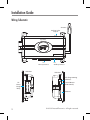
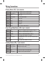
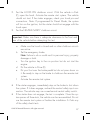
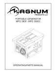
Model 24921 Owner’s/Installation Guide Congratulations Congratulations and thank you for purchasing one of our state-of-the-art remote start systems. Directed is the world leader in vehicle security, remote start, and keyless entry systems, so yes, you have made the right choice! STOP! Read this First Please make sure you follow all the steps listed below before attempting to install this system in your vehicle. Step 1: Watch the instructional DVD included with this system. Step 2: Read this guide from cover to cover. Step 3: Register at www.readyremote.com to gain access to our vehicle database. This provides you with the specific installation information for your vehicle and identifies any additional hardware, if needed, to support the features you desire. Step 4: Ensure you have, or can borrow the items listed in the Tools Required section of this guide. If you find that this installation is too difficult to perform, please visit the Professional Installer Network section of the www.readyremote.com web site or visit: www.proinstallation.com to contact one of our 7,000 authorized retailers to have the product professionally installed. Caution! Failure to properly install this product may result in costly damages, personal injury, or both. © 2010 Directed Electronics. All rights reserved. iii What's Included • • • • • • • • • • • • Control Module One 1- Button Remote Control Control Button (Valet Switch) Antenna and Cable Harnesses Hood Pin Switch Hardware Kit Neutral Safety Switch Bypass Module (24921B only) Your Warranty Registration Card DVD - Do-It-Yourself Installation Video This Guide Tools Required • • • • • • • • • • Digital Multi-Meter Drill 1/4 Drill Bit (for hood pin switch) Screwdrivers (Phillips and Flathead) Wire Stripper Solder Iron Electrical Tape Pliers Crimping Tool Safety Glasses Note: The installation tools listed above may be optional. The required tools will vary depending on your vehicle. iv © 2010 Directed Electronics. All rights reserved. Important Information Government Regulations and Safety Information Read the Government Regulations and Warning! Safety First sections of this guide prior to operating this system. Warning! Failure to heed this information can result in death, personal injury or property damage and may also result in the illegal use of the system beyond its intended purpose. Your Warranty Your system comes with a warranty. Your product warranty must be validated following your purchase. You can validate online at: www. prodregister.com/directed or complete and return the warranty registration card. Replacement Remote Controls If additional remote controls are desired, please see your authorized dealer or visit us at www.readyremote.com to order. Your replacement part number is 7111R (1-button). Installation Guide The installation guide included within is abbreviated. If more information is required, please consult the expanded version which can be found under On-line Tech Support at www.readyremote.com. © 2010 Directed Electronics. All rights reserved. v Guide Translations If you want a Spanish or French version of the Installation/Owners Guide, please download it from www.readyremote.com and click on On-Line Tech Support. Estimado Cliente: Si buscas los guías de instalación/del usario, por favor de bajar lo del Soporte Técnico en-línea en el sitio www.readyremote.com Cher consommateur: Si vous désirez une version française ou espagnole du guide d’utilisateur ou d’installation, veuillez s.v.p. le télécharger à l’adresse suivante: www.readyremote.com en appuyant sur l’icône <<On-line Tech Support>>. vi © 2010 Directed Electronics. All rights reserved. Contents Congratulations................................................................................................ iii STOP! Read this First......................................................................................... iii What's Included ............................................................................................ iv Tools Required.................................................................................................. iv Important Information......................................................................................... v Your Warranty........................................................................................... v Replacement Remote Controls...................................................................... v Installation Guide...................................................................................... v Guide Translations.................................................................................... vi Installation Guide...............................................................................................2 Wiring Schematic......................................................................................2 Wiring Connections...........................................................................................3 Installation Points...............................................................................................4 Virtual Tach...............................................................................................4 Tach Learning............................................................................................5 Reset and Deletion.............................................................................................5 Remote Start Shutdown Diagnostics......................................................................6 Programming System Features.............................................................................7 Feature Menu....................................................................................................9 Remote Control Programming............................................................................10 Owner's Guide . .............................................................................................11 System Maintenance................................................................................11 Battery Replacement.................................................................................11 Using the system ............................................................................................11 Car Finder..............................................................................................11 Remote Start............................................................................................11 Valet Take-Over.......................................................................................13 Government Regulations...................................................................................14 Warning! Safety First........................................................................................15 Caution..................................................................................................16 Safety Check...................................................................................................16 Lifetime Consumer Warranty..............................................................................19 Installation Guide Wiring Schematic Antenna Parking Light Jumper Side View Side View LED (Pro indicato Top View Control (Valet S H2 avy uge elay Antenn H1 Primary Harness Antenna Parking Light Jumper Side View H3 Auxiliary Harness Antenna Parking Light Jumper Side View LED (Programming Top View indicator) Top View H2 Heavy Gauge Relay Control Button (Valet Switch) Antenna H1 Primary Harness 2 H3 Auxiliary Harness H1 Primary Harness H3 Auxiliary Harness © 2010 Directed Electronics. All rights reserved. Wiring Connections Primary Harness (H1), 9-pin connector H1/1 LIGHT GREEN BLACK (-) 200mA FACTORY ALARM DISARM H1/2 GREEN/WHITE (-) 200mA FACTORY ALARM REARM H1/3 EMPTY NOT USED H1/4 WHITE/BLUE (-) ACTIVATION INPUT H1/5 EMPTY NOT USED H1/6 EMPTY NOT USED H1/7 EMPTY NOT USED H1/8 BLACK GROUND H1/9 WHITE (+/-) LIGHT FLASH OUTPUT Heavy Gauge Relay Harness (H2), 6-pin connector H2/1 PINK OUTPUT TO PRIMARY IGNITION CIRCUIT, 30A (+) H2/2 PURPLE OUTPUT TO STARTER CIRCUIT, 30A (+) H2/3 ORANGE OUTPUT TO ACCESSORY CIRCUIT, 30A (+) H2/4 RED (+) (30A) HIGH CURRENT 12V INPUT H2/5 PINK/WHITE PROGRAMMABLE OUTPUT, 2ND IGNITION/ACCESSORY CIRCUIT 30A H2/6 RED (+) (30A) HIGH CURRENT 12V INPUT Auxiliary Harness (H3), 5-pin connector H3/1 BLACK/WHITE (-) NEUTRAL SAFETY SWITCH INPUT H3/2 VIOLET/WHITE TACHOMETER INPUT WIRE H3/3 BROWN (+) BRAKE SHUTDOWN INPUT WIRE H3/4 GRAY (-) HOOD PIN SWITCH SHUTDOWN WIRE H3/5 BLUE/WHITE (-) 200 mA STATUS/REAR DEFOGGER © 2010 Directed Electronics. All rights reserved. 3 Control Button (valet switch), 2-pin connector 1 BLACK INPUT 2 GREY OUTPUT Installation Points Note: The LED referenced within the installation section is the LED (programming indicator) on the Control Module unless otherwise stated. Virtual Tach Note: Use of Virtual Tach does not require the Tach wire to be connected. To program Virtual Tach: 1. After the install is complete, remote start the engine. The programming operation may require 3 cranks of the starter before the engine starts and runs. Do not turn off the remote start if this happens, it is a normal programming operation. 2. Once the engine begins running, let it run for at least 30 seconds. 3. Using the Remote, send the Remote start command to turn remote start off. Virtual Tach is programmed. Note: Virtual Tach is not recommended for diesel trucks. Virtual Tach handles disengaging the starter motor during remote starting – it does not address over-rev. For over-rev protection capability, the tach wire must be connected. Important: After successfully learning Virtual Tach, a small minority of vehicle starters may over crank or under crank during remote start. Virtual Tach fine tune can be adjusted, see Feature Menu and Programming System Features. 4 © 2010 Directed Electronics. All rights reserved. Tach Learning Note: Tach learning requires H3/2 (Violet/White) wire to be connected to Tach. If using Virtual Tach, this procedure is not required and should not be used. To learn the tach signal: 1. Start the vehicle with the key. 2. Within 5 seconds, press and hold the Control button. 3. After 3 seconds the LED will light constant when the tach signal is learned. 4. Release the Control button. Reset and Deletion If a feature/virtual tach needs to be reset or the remote controls need to be deleted, use the following procedure. 1. Turn the ignition to the On position (The heavy gauge pink wire must be connected). 2. Within 10 seconds, press and release the Control button: 2 times if you want to delete remote controls, 3 times to reset features or 4 times to reset virtual tach. These features are described next. Delete remote controls: This feature erases all remote controls from the memory of the system. This is useful in cases when a remote control is lost or stolen. You can program new remote controls to the system, see Remote Control Programming section of this guide. Note: This does not reset the programmed features of the system or reset the Virtual Tach setting. Reset Features: This resets all features of the system to the fac© 2010 Directed Electronics. All rights reserved. 5 tory default settings. Note: This feature does not delete the remote controls from the system or reset the Virtual Tach setting Virtual Tach Reset: Deletes all previously learned values for Virtual Tach, and on the next remote start sequence the unit begins virtual tach initialization. 3. Once you have selected the function step, press the Control button once more and hold it. The LED flashes to confirm the selected functional step. Do not release the Control button 4. While holding the Control button, press the button on the remote control. The LED flashes to confirm that the feature has been successfully reset. Once the feature is reset, the Control button can be released. Remote Start Shutdown Diagnostics To perform shutdown diagnostics: 1. With the ignition Off, press and hold the Control button. 2. Turn the ignition On and then back Off while holding the Control button. 3. Release the Control button. 4. Press and release the Control button. The LED flashes to report the last shutdown for one minute or until the ignition is turned on, as shown in the following table: LED Flashes 1 flash 2 flashes 3 flashes 6 Shutdown Mode Timed out Over-rev shutdown Low or no RPM, low battery (voltage and virtual tach modes) © 2010 Directed Electronics. All rights reserved. 4 5 6 7 8 flashes flashes flashes flashes flashes Transmitter shutdown (or optional push button) (-) Hood Shutdown (H3/4 Gray) (+) Brake Shutdown (H3/3 Brown) (-) Neutral safety shutdown (H3/1 Black/White) Wait-to-start timed out Programming System Features The System Features Learn Routine dictates how the unit operates. It is possible to access and change most of the feature settings (see Feature Menu) using the Control button. 1. Turn the ignition on, then off. 2. Select a Feature: Press and release the Control button the number of times corresponding to the feature you wish to change. Then press and hold one more time to select the feature. The LED flashes to indicate which feature # is selected. 3. Program the Feature: While holding the Control button, you can program the feature using the remote control. The remote control button selects the options in ascending order. The LED flashes indicating which option is selected. Once a feature is programmed: • Other features can be programmed within the menu • The learn routine can be exited if programming is complete To access another feature in the same menu: 1. Press and release the Control button the number of times necessary to advance from the feature you just programmed to the next one you want to program. Then press the Control button once more and hold it. © 2010 Directed Electronics. All rights reserved. 7 The learn routine exits if any of the following occurs: • The ignition is turned On • There is no activity for 30 seconds • The Control button is pressed too many times 8 © 2010 Directed Electronics. All rights reserved. Feature Menu Default settings are in bold type. Feature # Feature Opt. 1 Opt. 2 Opt. 3-5+ 1 Engine checking Virtual tach voltage (3) Off, (4) Tachometer 2 Remote Start Engine Runtime 12 min 24 min 60 min 3 Park light output Pulsed Constant 4 Cranking time 0.6 sec. 0.8 sec. (3) 1.0 sec. (4) 1.2 sec. (5+) 1.4, 1.6, 1.8, 2.0, 4.0 sec. 5 Remote Start 1 pulse activation pulse count 2 pulses 3 pulses 6 2nd Ignition / Acc Output Ignition Accessory 7 Accessory output Off during wait-to-start On during wait-to-start 8 Status behavior Normal Latch rear defogger Pulse rear defogger 9 Diesel Wait-ToStart timer Off Timed 15 sec Timed (3) 30 sec. (4) 45 sec. 10 Virtual Tach fine tune 0 (as learned) 100 ms to 1 sec. (in 100 ms increments) 11 Factory Alarm Disarm Pulses Single Double © 2010 Directed Electronics. All rights reserved. 9 Remote Control Programming 1. Turn key to the ON position 2. Within 5 seconds, press and release Control button one time. 3. Within 5 seconds, press and hold the Control button. The LED will flash one time to confirm entry into remote programming. 4. Press the button on the remote control. 5. The LED flashes to confirm the remote has been programmed. 6. Release the Control button, and turn the key to the Off position. 7. The LED turns on solid for a while to confirm that remote programming has been exited. The programming routine exits if any of the following occurs: • The ignition is turned off • There is no activity for 30 seconds • The Control button is pressed too many times 10 © 2010 Directed Electronics. All rights reserved. Owner's Guide System Maintenance The system requires no specific maintenance beyond battery replacement for the remote control. Your remote is powered by a coin cell battery (3V CR2032) that lasts approximately one year under normal use. When the battery begins to weaken operating range is reduced. Battery Replacement Locate the small slot on the side of the remote control. Insert a small slotted screwdriver or equivalent tool into slot and pry the case apart. Replace battery while verifying the correct polarity and then snap case together. Using the system Car Finder Car finder allows you to locate your vehicle, by having the system flash the parking lights. Before the vehicle is remotely started via the remote control, press and hold the remote control button for 3 seconds to activate the car finder function. The parking lights flash 5 times slowly. Remote Start This feature allows you to remotely start and run your vehicle for a programmable period of time. This makes it possible to warm up the engine, and adjust the interior temperature of the vehicle with the climate control system. If interior heating or cooling is desired, the climate controls must be preset, and the fan blower must be set to the desired level prior to remote starting the vehicle. © 2010 Directed Electronics. All rights reserved. 11 Sirius Warning! (1) Never remote start your vehicle when the keys are in the ignition, except when performing Valet Take-Over, and (2) Never start the vehicle if it is not in PARK or NEUTRAL To remote start the vehicle: • Press the button on the remote control once (default)*. • The parking lights flash to confirm that the vehicle is attempting to start. In gasoline vehicles the engine starts 4 seconds after the parking lights flash, in diesel vehicles the engine starts after the Wait-To-Start timer has expired (default is Off)*. • Once the vehicle has started, it will run for 12 minutes (default)*, or until a shutdown input is triggered. Bank and * Defaults: Remote Start Activation Pulse Count Channel (button presses), WaitTune mode present and text indicator indicator indicator To-Start timer and Engine Runtime can be changed, see corresponding Sat mode, features in Feature Menu and Programming System Features. bank selector AM/FM Category Control 11:53 Warning! It is unsafe to operate a vehicle’s motor in XM1-1 CH-001 aSEgarage or other closed off area. Breathing the ex EK SKIP haust from the vehicle is hazardous to your health. Never activate1the remote start in an 2 3 4 enclosed 5 6space. CATEGORY CD/AUX SAT RADIO REW Toggles Scan mode CH PLAY/PROG FF NR DISC- RPT DE DISP - MO A.SEL RDM TUNE DISC+ SOUND SCAN When you are ready to drive the vehicle:VOL 1. Insert the ignition key and turn it to the On (not the START) position. AUDIO 2. Press the brake pedal. The remote start system shuts down E and the PWR MOD A/C engine continues to run because the ignition has been turned on. A SC OU TP Text s Hold chan Sirius tune Cha Pres Hold save SC OU TP UTO F Note: If the brake pedal isOFpressed before the key is in the On position, DUA L Sat mode, Tune mode indicator bank selector Bank and present indicator Bank and present indicator Tune mode indicator Channel and text indicator Channel and text Indicator fields Text s Hold chann the engine will shut down. While the vehicle is running during remote start operation, the system monitors the vehicle and automatically shuts down the engine if it receives any of the following shut-down inputs: • • • • • The brake pedal is pressed. The hood is opened. The shutdown toggle switch is put into the Off position. The pre-programmed run time has elapsed. Remote control button is pressed and held for 3 seconds. Valet Take-Over The Valet Take-Over feature allows the vehicle to remain running after the key has been removed from the ignition. This feature is useful for occasions when you wish to exit and lock the vehicle for short periods of time, but would like to leave the engine running and the climate controls on. To perform Valet Take-Over: 1. Before turning off the engine, press and release the button on the remote control for 1 second. 2. Turn the ignition key to the Off position. The engine will stay running until the pre-programmed time has elapsed or a shutdown input is received. (See the previous Remote Start section for a complete list of shut-down inputs.) Important: This feature will not work if the brake pedal is being pressed. © 2010 Directed Electronics. All rights reserved. 13 Government Regulations This device complies with Part 15 of FCC rules. Operation is subject to the following two conditions: (1) This device may not cause harmful interference, and (2) This device must accept any interference received, including interference that may cause undesirable operation. This equipment has been tested and found to comply with the limits for a class B digital device, pursuant to Part 15 of the FCC Rules. These limits are designed to provide reasonable protection against harmful interference in a residential installation. This equipment generates and can radiate radio frequency energy and, if not installed and used in accordance with the instruction manual, may cause harmful interference to radio communications. However, there is no guarantee that interference will not occur in a particular installation. If this equipment does cause harmful interference to radio or television, which can be determined by turning the equipment OFF and ON, the user is encouraged to try to correct the interference by one or more of the following measures: • Reorient or relocate the receiving antenna. • Increase the separation between the equipment and receiver. • Connect the equipment into an outlet on a circuit different from that to which the receiver is connected. • Consult the dealer or an experienced radio / TV technician for help. This device complies with the Industry Canada Radio Standards Specification RSS 210. Its use is authorized only on a no-interference, no-protection basis; in other words, this device must not be used if it is determined that it causes harmful interference to services authorized by IC. In addition, the user of this device must accept any radio interference that may be received, even if this interference could affect the operation of the device. Warning: Changes or modifications not expressly approved by the party responsible for compliance could void the user’s authority to operate this device. 14 © 2010 Directed Electronics. All rights reserved. Warning! Safety First The following safety warnings must be observed at all times: Due to the complexity of this system, installation of this product must be done properly according to instructions with safety always considered. Failure to properly install this system and its safety features may result in personal injury, property damage or both. When properly installed, this system can start the vehicle via a command signal from the remote control. Therefore, never operate the system in an enclosed area or partially enclosed area without ventilation (such as a garage). When parking in an enclosed or partially enclosed area or when having the vehicle serviced, the remote start system must be disabled using the installed toggle switch. It is the user’s sole responsibility to properly handle and keep out of reach from children all remote control devices to assure that the system does not unintentionally remote start the vehicle. THE USER MUST INSTALL A CARBON MONOXIDE DETECTOR IN OR ABOUT THE LIVING AREA ADJACENT TO THE VEHICLE. ALL DOORS LEADING FROM ADJACENT LIVING AREAS TO THE ENCLOSED OR PARTIALLY ENCLOSED VEHICLE STORAGE AREA MUST AT ALL TIMES REMAIN CLOSED. These precautions are the sole responsibility of the user. Use of this product in a manner contrary to its intended mode of operation may result in property damage, personal injury, or death. (1) Never remotely start the vehicle with the vehicle in gear, and (2) Never remotely start the vehicle with the keys in the ignition. The user must also have the neutral safety feature of the vehicle periodically checked, wherein the vehicle must not remotely start while the car is in gear. This testing should be performed by an authorized professional Directed dealer. If the vehicle starts in gear, cease remote start operation immediately and consult with the authorized Directed dealer to fix the problem. After the remote start module has been installed, perform the Safety Check © 2010 Directed Electronics. All rights reserved. 15 outlined in this guide. If the vehicle starts when performing the Neutral Safety Shutdown Circuit test, the remote start unit has not been properly installed. The remote start module must be removed or properly reinstalled so that the vehicle does not start in gear. OPERATION OF THE REMOTE START MODULE IF THE VEHICLE STARTS IN GEAR IS CONTRARY TO ITS INTENDED MODE OF OPERATION. OPERATING THE REMOTE START SYSTEM UNDER THESE CONDITIONS MAY RESULT IN PROPERTY DAMAGE OR PERSONAL INJURY. YOU MUST IMMEDIATELY CEASE THE USE OF THE UNIT AND SEEK THE ASSISTANCE OF AN AUTHORIZED DIRECTED DEALER TO REPAIR OR DISCONNECT THE INSTALLED REMOTE START MODULE. DIRECTED WILL NOT BE HELD RESPONSIBLE OR PAY FOR INSTALLATION OR REINSTALLATION COSTS. Caution This product is designed for fuel injected, automatic transmission vehicles only. Use of this product in a standard transmission vehicle is dangerous and contrary to the product's intended use. Safety Check Before vehicle reassembly, the remote system must be checked to ensure safe and trouble-free operation. The following test procedure must be used to verify proper installation and operation of the system. The installation must be completed before testing, including connection to the brake switch and hood switch. 1. Test the BRAKE shutdown circuit: With the vehicle in Park (P), activate the remote start system. Once the engine is running, press the brake pedal. The engine should shut down immediately. If the engine continues to run, check the brake circuit connection. 16 © 2010 Directed Electronics. All rights reserved. 2. Test the HOOD PIN shutdown circuit: With the vehicle in Park (P), open the hood. Activate the remote start system. The vehicle should not start. If the starter engages, check your hood pin and connections. Note: If programmed for Diesel Mode, the system will turn on the ignition, but the starter should not engage with the hood open. 3. Test the NEUTRAL SAFETY shutdown circuit: Important: Make sure there is adequate clearance to the front and rear of the vehicle before attempting this test. a. Make sure the hood is closed and no other shutdown circuits are active. b. Set the emergency brake. Note: Failure to do so could result in personal injury, property damage or both. c. Turn the ignition key to the run position but do not start the engine. d. Put the vehicle in Drive (D). e. Put your foot over the brake pedal but do not press down on it. Be ready to step on the brake to shutdown the remote start system. f. Activate the remote start system. • • If the starter engages, immediately step on the brake to shut down the system. If it does engage, recheck the neutral safety input connection. The vehicle may use a mechanical neutral safety switch. If the starter does not engage, the test is complete. Once the system passes all three tests, the vehicle can be re-assembled. Do not use the remote start system or finalize the installation if it fails any of the safety check tests. © 2010 Directed Electronics. All rights reserved. 17 Patent Information This product is covered by one or more of the following U.S. patents: 303,223 345,711 4,383,242 5,103,221 5,534,845 5,907,195 333,633 347,190 4,438,426 5,117,217 5,572,185 5,914,667 333,634 348,622 4,553,127 5,132,660 5,646,591 5,945,936 333,635 352,685 4,584,569 5,193,141 5,656,997 5,952,933 333,636 383,689 4,794,368 5,245,694 5,712,638 5,990,786 6,093,979 333,795 383,690 4,887,064 5,285,186 5,783,989 340,000 390,830 4,897,630 5,315,285 5,798,711 344,905 392,944 4,922,224 5,357,560 5,872,519 345,317 4,327,444 4,987,402 5,532,670 5,900,806 International Patents: Australia: 694,925 Canada: 1,315,859 and 2,067,099 Taiwan: 91817 Other patents pending 18 © 2010 Directed Electronics. All rights reserved. Lifetime Consumer Warranty For a period of one calendar year from the date of purchase of this auto-security, remote start or keyless entry device, as applicable (hereinafter “Unit”), Directed Electronics (“Directed”) promises to the ORIGINAL PURCHASER to repair or replace (at Directed’s election) with a comparable, reconditioned Directed DIY Unit (excluding without limitation, the siren, remote transmitters and associated sensors and accessories) which proves to be defective in workmanship or material under reasonable use PROVIDED the following conditions are met: (i) the Unit was purchased from an authorized Directed dealer, (ii) the Unit is returned (shipping prepaid) to Directed’s warranty department at: Directed Electronics, Attn: Warranty, One Viper Way, Vista, CA 92081, along with a cashier’s check or money order made payable to Directed Electronics in the amount of $20 for postage and handling, and (iii) a bill of sale or other dated proof of purchase bearing the following information is included: Date of purchase, name and location of merchant who sold the Unit and product description. This warranty does not cover labor costs for the removal or reinstallation of the Unit. This warranty is non-transferable and does not apply to any Unit that has been modified or used in a manner contrary to its intended purpose, and this warranty does not cover damage to any Unit caused by installation or removal of the Unit. This warranty is void if the Unit has been damaged by accident or unreasonable use, negligence, Acts of God, improper service or other causes not arising out of defects in materials or workmanship. If this Unit is an auto-security device, then the Unit may be a deterrent against possible theft, however Directed makes no warranty against vandalism, damage or theft of a vehicle or its parts or contents and Directed expressly disclaims any liability whatsoever, including without limitation, liability for theft, damage and/or vandalism. ALL UNITS RECEIVED BY DIRECTED FOR WARRANTY REPAIR WITHOUT PROOF OF PURCHASE WILL BE DENIED. THE FOREGOING WARRANTY IS THE EXCLUSIVE PRODUCT WARRANTY, OTHERWISE, ALL WARRANTIES, INCLUDING BUT NOT LIMITED TO EXPRESS WARRANTY, IMPLIED WARRANTY, WARRANTY OF MERCHANTABILITY FOR FITNESS FOR A PARTICULAR PURPOSE ARE EXPRESSLY EXCLUDED AND DISCLAIMED TO THE MAXIMUM EXTENT ALLOWED BY LAW, AND DIRECTED NEITHER ASSUMES NOR AUTHORIZES ANY PERSON TO ASSUME FOR IT ANY LIABILITY IN CONNECTION WITH THE SALE OF THE PRODUCT. DIRECTED HAS ABSOLUTELY NO LIABILITY FOR ANY AND ALL ACTS OF THIRD PARTIES INCLUDING ITS AUTHORIZED DEALERS OR INSTALLERS. SOME STATES DO NOT ALLOW LIMITATIONS ON HOW LONG AN IMPLIED WARRANTY WILL LAST OR THE EXCLUSION OR LIMITATION OF INCIDENTAL OR CONSEQUENTIAL DAMAGES, SO THE LIMITATIONS HEREIN MAY NOT APPLY TO YOU. © 2010 Directed Electronics. All rights reserved. 19 Consumer’s remedy is limited to repair or replacement of the Unit, and in no event shall Directed’s liability exceed the purchase price of the Unit. IN ANY EVENT, DIRECTED SHALL NOT BE LIABLE FOR ANY DAMAGES, INCLUDING, BUT NOT LIMITED TO, ANY DIRECT, INDIRECT, INCIDENTAL, SPECIAL, PUNITIVE OR CONSEQUENTIAL DAMAGES, LOST PROFITS, DAMAGE TO VEHICLE, LOST SAVINGS, OR, TO THE EXTENT ALLOWED BY APPLICABLE LAW, DAMAGES RESULTING IN DEATH OR INJURY ARISING OUT OF OR IN CONNECTION WITH THE INSTALLATION, USE, IMPROPER USE, OR INABILITY TO USE THE PRODUCT, EVEN IF THE PARTY HAS BEEN ADVISED OF THE POSSIBILITY OF SUCH DAMAGES. The consumer consents and agrees that all disputes between the consumer and Directed shall be resolved in accordance with California laws in San Diego County, California. This warranty is only valid for the sale of product(s) within the United States of America. Product(s) sold outside of the United States of America are sold “AS-IS” and shall have NO WARRANTY, express or implied. IMPORTANT NOTE: This product warranty is automatically void if its date code or serial number is defaced, missing, or altered. This warranty will not be valid unless you have completed the warranty card and mailed it to Directed within 10 days after purchase to the address listed on the warranty registration card. Make sure you have all of the following information from your dealer: A clear copy of the sales receipt, showing the following: • Date of purchase • Authorized dealer’s company name and address • Item number 920-0005 2007-08 20 © 2010 Directed Electronics. All rights reserved. The company behind this system is Directed Electronics Since its inception, Directed Electronics has had one purpose, to provide consumers with the finest vehicle security and car stereo products and accessories available. The recipient of nearly 100 patents and Innovations Awards in the field of advanced electronic technology, DIRECTED is ISO 9001 registered. Quality Directed Electronics products are sold and serviced throughout North America and around the world. Call (800) 274-0200 for more information about our products and services. Directed Logo Usage Logo, Directed with designed in USA.eps Directed Electronics is committed to delivering world class quality products and services that excite and delight our customers. Logo, Directed Electronics w-driven.eps Directed Electronics Vista, CA 92081 www.directed.com Logo, Directed with Distributed By.eps © 2010 Directed Electronics—All rights reserved QRN24921 2010-07