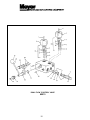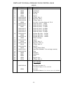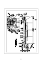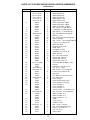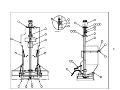
1
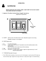
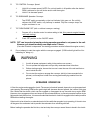
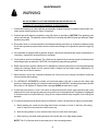
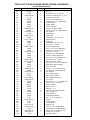
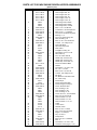
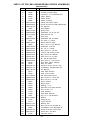
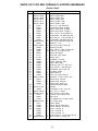
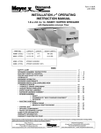
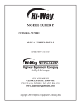
Form No. 1-739 R May, 2000 INSTALLATION and OPERATING INSTRUCTION MANUAL MDV SPREADER 4 4 PART NO. 62228 62234 62246 MODEL M-940 M-944 M-1044 LENGTH 9 FT. 9 FT. 10 FT. CAPACITY 3.4 CU YD 4.2 CU YD 4.7 CU YD RATING 17,000 19,000 20,000 INCLUDED IN THIS MANUAL SAFETY ALERT............................................................................... 2 SPREADER ASSEMBLY INSTRUCTIONS ..................................... 3-5 SPREADER OPERATION .............................................................. 6-8 SPREADER MAINTENANCE .......................................................... 9 HYDRAULICS .............................................................................. 10-11 SPREADER PARTS LISTS & EXPLODED VIEW .......................... 12-36 WARRANTY ................................................................................... 37 Meyer Products reserves the right, under its continuing product improvement program, to change construction or design details, specifications and prices without notice or without incurring any obligation. www.meyerproducts.comemail [email protected] Printed in U.S.A. ©2000 1 18513 Euclid Ave. Cleveland, Ohio 44112-1084 Phone 486-1313 (Area Code 216) THE BEST SAFETY DEVICE IS A CAREFUL OPERATOR! SAFETY ALERT SYMBOL ! THIS SYMBOL MEANS ATTENTION! BECOME ALERT! YOUR SAFETY IS INVOLVED! PLEASE READ AND UNDERSTAND COMPLETELY BEFORE DOING! SAFE EQUIPMENT INSTALLERS AND OPERATORS: ! TURN OFF ALL POWER BEFORE PERFORMING ANY SERVICE OPERATIONS FOLLOW RECOMMENDED OPERATING PROCEDURES. KEEP EQUIPMENT IN SAFE OPERATING CONDITION AT ALL TIMES. RECOGNIZE AND AVOID HAZARDS WHILE OPERATING, SERVICEING AND MAINTAINING EQUIPMENT. ! REFER TO THE ENGINE OPERATING & MAINTENANCE MANUAL FOR SPECIFIC SAFETY PRECAUTIONS FOR THIS ENGINE. ! CAUTION DANGER Stay clear while spinner is turning 1. KEEP ALL SHEILDS IN PLACE. 2. MAKE CERTAIN EVERYONE IS CLEAR BEFORE STARTING MACHINE OR MOVING VEHICLE. 3. KEEP HANDS, FEET, AND CLOTHING AWAY FROM ALL POWER DRIVEN PARTS. 4. DISENGAGE p.t.o., SHUT OFF HYDRAULIC VALVE AND SET PARKING BRAKE BEFORE LEAVING OPERATORS POSITION. MAKE SURE ALL MOVEMENT HAS STOPPED BEFORE SERVING OR UNCLOGGING MACHINE. 5. USE FLASHING LIGHTS WHEN OPERATING MACHINE. 6. MAKE SURE MACHINE IS SOLIDLY SUPPORTED WHEN IT IS BEING MOUNTED, DISMOUNTED, OR STORED. DANGER Turn off power before servicing. NOTICE: Instructional Material And Parts Lists Included In This Manual Are Subject To Change Without Notice. 2 ASSEMBLY INSTRUCTIONS AND INSTALLATION INSTALLATION INSTRUCTIONS: The Meyer MDV Series Spreaders can mount and store as a single unit. The Meyer MDV Series Spreader will mount on most 15,000-20,000 GVW trucks as well as larger trucks. ! ! WARNING DO NOT OVERLOAD THE VEHICLE. It is quite possible to overload the vehicle by improperly mounting or over loading the spreader. This could result in dangerous stability and braking problems. Always consult and follow the truck manufacturers instructions. WARNING BEFORE BEGINNING ANY INSTALLATION ON THIS UNIT, disconnect the spreader battery negative cable if already installed. 1. Place the spreader in the rear of truck with the engine / hydraulic motor to the rear of the truck. Center the spreader (side to side) in the truck. The spreader should extend past the rear of the outer most part of the truck (i.e: truck bed, bumper) approximately 18 inches. ! Caution: Insure that the spreader cannot tip when the spinner assembly is attached. SPINNER ASSEMBLY a. Raise engine shroud and prop it open with the support rod. (if engine driven model) b. Slide the spinner frame assembly into the rear of the longitudinals with the spinner back plate toward the rear. c. Bolt the spinner to the longitudinals using the four (4) 3/8" x 1 bolts, 3/8 flange nuts and flatwashers from hardware bag located on the spinner. Using one (1) 3/8" x 1" bolts, flatwashers and flange nut from hardware bag, bolt the top portion of the spinner back plate to the engine plate. d. Install roller chain between the gear box sprocket and the spinner sprocket. Make sure sprockets are in line with each other. The roller chain is tightened, first by loosening all four 3/8" bolts on the back plate. Then, pull the entire bearing/shaft assembly in such a way to achieve the proper amount of chain tension. Make sure the spinner shaft is straight up and down before retightening. 2. Reposition the spreader in the truck, just short of making contact with the rearmost part of the truck bed, bumper, pintle hook etc. Bolt the unit to the truck using a minimum of six 1/2" - grade 5 bolts and corresponding washers and locknuts. The Spreader is designed to sit flat on the bed of the truck, supported by the longitudinal/sides. DO NOT SUPPORT THE SPREADER BY THE BODYJACKS ALONE !! UNIT IS NOT DESIGNED FOR CHASSIS MOUNT APPLICATION ! 3 INSTALLATION INSTRUCTION FOR ELECTRIC THROTTLE CONTROL ! WARNING 1. Disconnect battery, NEGATIVE CABLE (if already installed). 2. Spreaders with factory installed throttle controls do not require installer hook-up to the engine. The actuator has been installed and tested at the factory. 3. Raise the engine shroud and securely prop it in place with the prop rod. The installer will have to remove the ties securing the coiled actuator cable to the top of the engine. 4. The throttle actuator cable plugs into the in-cab control panel after being routed from the cab of the vehicle to the rear of the mounted spreader. 5. Select a suitable location in the cab of the vehicle to mount the throttle control box. (Do not mount at this time.) ! WARNING Consult vehicle manufacturer for acceptable mounting locations. Improperly mounting the control box could interfere with air bag(s) and the other functions of the occupant protection systems, such as knee bolsters! 6. After the location of the control panel is determined, the cable must be routed to the rear of the spreader, so the hookup can be made with the actuator cable plug. Route the conductor cable, attached to the control, to rear of truck, under truck, securing as needed. Allow enough cable for the control panel to be mounted in the cab. 7. The routed cable must be clear of all moving or hot parts on the spreader or vehicle. Secure the cable with the ties provided. Excess cable must be coiled up and secured. 8. Locate and mount the control panel (with screws supplied). 9. For permanent cable mount at rear of the truck, a mounting bracket is supplied. 10. Slide boot over cable then, wire the control panel cable end into the socket (wire colors and locations are identified on the socket). The rubber socket boot must be installed for weather resistant seal. 11. Fill boot from cable side with a good grade of dielectric grease to help reduce corrosion on terminals. 12. Install a 12 volt battery with 4- ampere hour rating, recommended for winter use (if not already done). The battery hold-downs furnished will accept any 2 SM Series battery. 4 ! WARNING Use safety glasses or other face protection against possible battery explosion. Do not smoke and avoid other sources of ignition. 13. Attach the positive battery cable (each end must have a rubber boot) to the positive terminal of the solenoid and to the positive terminal of the battery Make sure these protective boots are covering the positive terminal post on the battery and on the solenoid. 14. Connect the negative battery terminal to the battery hold down post. When finished, make sure all wires are away from moving parts and lower engine shroud. 15. Plug cable from the spreader into socket mounted on the truck, Step 9. 5 OPERATION ! WARNING BEFORE OPERATING THE CONTROL PANEL - MAKE SURE THAT NO ONE IS INSIDE THE HOPPER OR NEAR THE SPINNER. 1. Electric Throttle Control Panel Switch functions (Sequence of Operations) ON OFF CHOKE START HI LO CONV. MOUNTING TABS RED LENSE A. ON/OFF System power activated (ready to start). Spreader engine is not running. Spreader conveyor is not engaged. B. START (Engine only) 1 . On 2. Choke 3. Start 4. LO / HI On switch depressed. (cold engine ) Hold down for 5 seconds to move the throttle actuator to the choke position. Note: Choking a warm engine may not be necessary Hold down until engine starts. Decreases / increases engine speed - adjust as engine warms up. Lo will stop the choke function. C. TO ENGAGE Spreader Conveyor 1. Push CONV switch only after you are sure no one is in the hopper or near the spinner! This lights up the red indicator light, if light does not light, take care to verify that the light is not malfunctioning. 6 D. TO CONTROL Conveyor Speed. 1. 2. E. Hold HI to increase speed. NOTE: Do not hold switch in HI position after the desired RPM is achieved or you will choke and/or stall the engine. Hold LO to decrease speed. TO DISENGAGE Spreader Conveyor. 1. F. Tap START switch momentarily so that red indicator light goes out. Do not fully depress the START switch, only half way is needed. Only the conveyor stops, the engine continues to run. TO TURN ENGINE OFF (with or without conveyor running). 1. Depress LO on throttle control to reduce setting to idle (this prevents engine flooding and hard starting). 2. Push OFF position on the ON/OFF switch. NOTE: OFF can be pushed at anytime during spreader operation to cut power to the unit. However, you should normally use steps under F above. (Once the off switch is depressed - the starting procedure must be followed for engine re-start.) G. Do not attempt to start the engine with the conveyor engaged. (CONV switch light will be lit to indicating its being on.) ! WARNING 1. 2. As with all power equipment, safety is the number one concern. Do not operate this equipment until you fully understand how it functions. 3. Before starting engine, be sure that no one is near the rear of the unit and that no one is inside the unit! 4. Do not start the engine or engage the conveyor (which is interconnected to the spinner); until everyone is clear from moving parts and flying material from the spinner. SPREADER OPERATION A. Start the engine and engage the clutch. The amount of material spread, depends on engine speed and gate opening. Decreasing RPM and/or gate height will decrease amount spread; the inverse holds true also. Notice that the electric clutch can be engaged or disengaged at any time and at any engine RPM. However, since engagement time and torque is almost instantaneous, to prevent premature spinner chain failure and chain tension loss, it is recommended that the electric clutch be engaged at the lowest possible RPM without stalling the engine. If the truck is to be driven for an extended period of time while the spreader is not operating, it is best to turn off the gas at the carburator inlet to prevent the carburator from overfilling with fuel. Before loading the spreader the first time, start and stop the conveyor several times to break in the clutch. 7 ! WARNING ALWAYS STAND AT A SAFE DISTANCE AWAY FROM THE SPINNER WHILE OPERATING ALWAYS WEAR EYE PROTECTION WHEN OUTSIDE OF THE TRUCK CAB WHILE SPREADER IS RUNNING. B. Spread pattern depends on baffle settings and spinner RPM. Maximum spread width is 30 ft. 1. Speeding up or slowing down the engine will increase or decrease spread pattern width. 2. Internal baffle adjustments will move the spread pattern to the right or left. 3. External baffle adjustments will block spreading to the right or left side. DESIRED SPREAD PATTERN BAFFLE SETTING INTERNAL EXTERNAL Both Down All Three UP RH - Up RH - Up LH - Down LH - Down RH - Down RH - Down LH - Down LH - Up RH - Down RH - Med. LH - Up LH - Up RH - Up RH - Up LH - Down LH - Med. RH - Down All - Down LH - Down Centered Behind Truck All Material to the Right All Material to the Left Behind Truck and Left Behind Truck and Right Windrow Behind Truck 4. External Baffles can be lowered to an intermediate position to baffle down the particles that may otherwise leave the spinner at a high trajectory. C. CALIBRATION The average lbs. of salt per gearbox shaft revolution per inch of gate height is 6.7 Ibs. GATE HEIGHT AVG. LBS/REV. 1 3 5 7" 6.7 20.1 33.5 46.9 AVG. LBS/MIN. AT FULL ENGINE RPM 260 780 1300 1800 8 AVG. LBS/MIN. AT 7 GPM HYD OIL FLOW 200 580 970 1350 MAINTENANCE ! WARNING DO NOT ATTEMPT TO LIFT THE SPREADER BY THE CENTER LIFT OR CORNER LIFT HOOKS WITH MATERIAL IN THE SPREADER. 1 Grease idler bearings on idler shaft take up assembly, outboard bearing on gearbox output shaft, and lower spinner bearing every ten hours of operation. 2. Grease input shaft bearing on gearbox every fifty hours of operation. CAUTION! Over greasing may cause seal damage. The gearbox must be filled to oil level plug with SAE 90 gear type lubricant. Keep breather plug clean. 3. Drag chain slack on V-boxes should be checked periodically and taken up if distance between center line of rear sprocket and point where chain contacts lower flange on longitudinal is less than eight (8) inches. 4. If the spreader is equipped with a gasoline engine, it should be maintained per engine manufacturers instruction. (Instructions and parts book is enclosed.) 5. V-belt tension must be maintained. The v-belt can be tightened by loosening engine hold-down bolts and sliding engine as required. CAUTION! Over tightening may damage gearbox. 6. Roller chain tension must be maintained. It is adjusted by loosening the spinner mounting bearings and sliding the bearings. Make sure the spinner shaft is straight up and down before retightening. Oil chain often and at end of season. 7. When the box is not in use, it should be washed out. If the box is put in storage, all surfaces should be oiled or painted after washing. 8. For HYDRAULIC SPREADERS, maintain oil level three fourths (3/4) full in reservoir with clean high grade non-foaming hydraulic oil; recommended viscosity 100-200 SSU. Operating temperature should be limited to 180 degress F. Replace filter cartridge #62382 at least twice a year. 9. If chain becomes stuck or froze to the floor to the point where the clutch cannot pull the load, never attempt to free chain using a pipe wrench or any other tool on the output shaft. The gearbox is designed to accept torque from input shaft only. Trying to turn output shaft will strip the gears, thus voiding the warranty. 10. To minimize problems and extend the life of the Electric Clutch, the following is highly recommended a. Before starting unit, make sure the drag chain is free (not stuck or froze to the floor). If the drag chain is stuck, this can cause the clutch to burn up. b. After the using season is over, remove clutch from unit, and clean thoroughly. c. After cleaning, coat both mating surfaces of the clutch with oil or light weight grease. NOTE: The Oil or Grease must be removed prior to the next using season. 9 HYDRAULICS ! WARNING Leaking high pressure fluids can inject themselves under the skin of persons near a leak, creating grave medical risks. TAKE CARE TO AVOID EXPOSURE TO HIGH PRESSURE FLUIDS. 1 . Hydraulic components should be kept as clean as possible during assembly operations. 2. Galvanized pipe and pipe fittings must not be used because flaking or galvanizing material can cause damage to major hydraulic components. 3. A pipe joint sealant, compatible with hydraulic oil, must be applied to all screwed fittings. (Teflon tape is not recommended.) 4. Hose should be protected where severe wear may be caused by vibration or sliding movement. 5. Long runs of hose should be supported by tie wiring or clamping. 6. Pressure and return hoses, connected to hydraulic motors, may be reversed for proper motor rotation. Spinner rotates in a clockwise direction when looking down from top. 7. Use hose manufacturers recommendations for fitting re-useable hose ends. 8. Hydraulic pumps must be mounted so shaft rotates in direction of arrow. 9. Locate reservoir as close to pump as possible. It may be installed on truck frame or truck box. 10. Hydraulic return line filter is screwed directly onto reservoir with cartridge down. Oil must flow through filter in direction of arrow on filter. 11. Install the quick connect couplings so that when disconnected, there is a male and female on the truck as well as on the spreader. This way, hoses will always be hooked up properly. and hose ends can be coupled together when spreader is in storage to prevent system contamination. 12. See page 11 for valve assembly 13. Operate hydraulic system for several minutes to warm up. Check all connections for leaks. 14. After running, refill reservoir to three fourths full. CONTROL AND HYDRAULIC SYSTEM SPECIFICATIONS *Hydraulic Oil ................................... Good Grade of MS10W Hydraulic Oil Which has wear, oxidation and foam inhibitors. *Oil Filter .......................................... 10 Micron Element Return Line Filter. *Relief Valve Setting1500 PSI *Oil Flow .......................................... 0 - 10 GPM - With single flow valve connect conveyor and spinner with dual flow valve. *Oil Flow .......................................... 0 - 15 GPM - With dual flow valve connect separate pressure line to conveyor and spinner motor. 10 DUAL FLOW VALVE/STAND INSTALLATION INSTRUCTIONS 1. IMPORTANT: A pipe joint sealant compatible with hydraulic oil must be applied to all screw fittings. (Teflon Tape Sealant Is Not Recommended) 2. Hose ends connected to flow valve must be of the swivel type. 3. CAUTION: Over tightening of the fittings in flow valve may cause damage to valve body 4. Approximately 8" of hose slack must be realized between the flow valve and valve stand after the flow valve has been completely plumbed. If this condition does not exist after the plumbing has been completed, removal of valve will require hoses to be removed at opposite end of valve. 5. Assembly of valve on stand: a. Cut a 5" x 5" square opening in floor board of truck where the valve stand is to be located. b. Bolt valve stand halves together forming a box over the 5" x 5" square opening. NOTE: When bolting valve stand halves in place, make sure holes in flanges align with holes in flange plate.* c. Bolt flange plate to VALVE (Use (2) 1/4" x 3" bolts, lockwashers, etc.) d. Insert hoses through floor opening and valve stand and connect appropriate hoses (see instructions #1 thru #4) to flow valve. e. Bolt flange plate to valve stand flanges. 11 DUAL FLOW CONTROL VALVE 62213 12 PARTS LIST FOR DUAL HYDRAULIC FLOW CONTROL VALVE (62213) Item 1 2 3 4 5 6 7 8 9 10 11 12 13 14 15 16 17 18 19 20 21 22 23 24 Part Number 62383 62098 62384 62385 62386 04105-285-06 04105-285-07 04105-285-08 62099 04105-285-10 04105-285-11 62387 04105-285-13 04105-285-14 04105-285-15 04105-285-16 62388 04105-285-18 62389 04105-285-20 62100 04105-032-30 62102 04105-285-24 62103 04105-032-21 04105-285-26 62390 62391 62392 62393 62104 Qty. 2 2 2 2 2 2 2 2 1 1 1 1 1 1 1 1 1 1 1 1 2 1 2 1 1 1 1 1 1 1 2 Description Screw Handknob Dowel Pin Roll Pin Spring O-Ring, Viton ® Back-up, Teflon O-Ring, Viton ® Kit, Seal - Consists of Items 6, 7 & 8 Auger Adj. Assy. - 7 GPM Auger Adj. Assy. -10 GPM Auger Adj. Assy. - 15 GPM Auger Adj. Assy. - 20 GPM Auger Adj. Assy. -25 GPM Auger Adj. Assy. - 30 GPM Spinner Adj. Assy. - 5 GPM Spinner Adj. Assy. - 7 GPM Spinner Adj. Assy. - 10GPM Relief Cartridge Gasket O-Ring, Viton ® Back-up, Teflon ® O-Ring, Viton ® Roll Pin O-Ring (Dump Stem) Stem (Not Available - Can no longer service) Plug Setscrew Handknob Lever Bypass Assy. O-Ring, Viton ® NOT SHOWN 04105-285-40 62394 Kit, Seal (For Item 11) Consists of Items: 12, 13, 14 & 15 Kit, Seal Consists of Items: 6, 7, 8, 12, 13, 14, 15, 17, 23 & 24 13 14 PARTS LIST FOR MDV ENGINE DRIVEN HOPPER ASSEMBLIES (Carbon Steel) Item 1 6 7 8 10 12 13 16 17 18 19 20 21 22 23 29 31 33 35 38 39 40 41 42 43 44 45 46 47 48 49 52 53 54 55 56 57 58 59 61 62 63 64 Part Number 00115-146-01 00115-146-02 00115-146-09 00115-146-10 00115-146-17 00115-146-18 62343 62344 62345 20091 20329 20051 04003-806-02 62355 20525 62302 20226 20307 62370 61171 61169 62300 20353 62304 62408 62310 62308 62306 00115-147-00M 62280 20354 04010-003-02 04003-033-12 20305 62270 61204 04045-025-00 21971 21932 62009 62292 62290 62288 62335 04003-032-06 62298 62296 62294 61162 61168 61176 04003-001-16 62187 62133 61196 61177 Qty. 1 1 1 1 1 1 1 1 1 4 6 2 10 2 25 2 8 8 1 1 1 1 7 2 10 2 2 2 1 1 1 1 7 8 1 2 2 2 1 2 1 1 1 1 1 1 1 1 1 1 1 4 4 1 1 1 15 Description Weld, Hopper 840 Weld, Hopper 844 Weld, Hopper 940 Weld, Hopper 944 Weld, Hopper 1040 Weld, Hopper 1044 Weld, Drag Chain, 8' MDV Weld, Drag Chain, 9' MDV Weld, Drag Chain, 10' MDV Bolt, 1/2-13 x 3/4 HH GR5 ZP Lockwasher, 1/2" Med Split ZP Bolt, 3/8-16 x 1-1/2 HH GR5 ZP Nut, 3/8-16 Serrated Flange ZP Bearing, 1-1/4" Nut, 5/16-18 Serrated Flange ZP Plate, Front Brg. Bolt, 1/2-13 x 1-3/4 Carriage GR5 ZP Locknut, 1/2-13 Nyl Ins ZP Weld, Idler Shaft Sprocket, Drag Chain Knob, Hand Feedgate, Forming Flatwasher, 3/8" U.S.S. ZP Weld, Take-up Nut, 1/2-13 Hex Jam ZP Shield, Rep. Chain 8 Shield, Rep. Chain 9 Shield, Rep. Chain 10' Instruction Manual MDV (1-739) Handle Flatwasher, 7/16" U.S.S. ZP Pin, 1/8" x 1" Cotter Bolt, 3/8-16 x 3/4 Carriage SS Locknut, 3/8-16 Nyl Ins ZP Bar, Pivot Pin, Master for Chn W/O Cotter Pin, Cotter Only Decal, Meyer Decal, Serial (w/Pat. Nos.) Decal, Danger (Conveyor) Floor, Forming, 8' Floor, Forming, 9' Floor, Forming, 10' Screw, 3/8-16 x 1-3/16" SLT FL HD Bolt, 5/16-18 x 3/4 Carriage SS Weld, Inverted V 8' Weld, Inverted V 9' Weld, Inverted V, 10' V-Belt Cover, Clutch Retainer, Clutch Bolt, 1/4-20 x 1 HH ZP Nut, 1/4-20 Serrated Flange Engine, 10-1/2 HP I/C Key, 1/4" Sq x 1 Pulley, Driver PARTS LIST FOR MDV ENGINE DRIVEN HOPPER ASSEMBLIES Item 65 66 67 68 69 70 71 73 74 75 76 77 78 79 80 81 82 83 84 85 88 91 94 95 96 97 98 99 100 101 104 105 106 107 109 111 112 113 115 116 117 118 119 120 121 124 125 126 127 128 129 130 131 132 133 134 135 136 (Carbon Steel)Continued Part Number Qty. Description 04003-002-06 61205 20352 04093-022-00 61179 62046 62188 62040 61213 62395 04607-004-00 62191 04607-001-00 61206 04604-017-00 20355 00115-140-01 61215 20353 61231 04049-199-00 20235 20354 04010-003-02 20202 20305 20048 04120-078-01 04110-006-03 20203 62105 62106 04003-081-04 20327 04607-001-00 62174 62169 00113-668-00 04093-021-00 20203 20600 62007 62354 61163 62284 62000 61178 61202 61201 00107-679-00 61161 61167 00108-771-00 04003-002-09 20326 04003-081-04 04001-001-01 61156 1 1 5 2 1 2 2 1 1 2 2 2 1 2 1 2 1 1 2 2 1 4 4 2 1 1 4 1 1 1 1 1 3 3 2 1 1 1 2 1 4 1 1 1 2 2 1 1 2 1 1 1 1 1 3 3 1 1 16 Bolt, 5/16-18 x 1-1/2 HH GR5 ZP Bolt, L Flatwasher, 5/16" U.S.S. ZP Grommet, CA Plug Type (1 1/4") Solenoid, Grounded Terminal, Insulated Ring Connector, 16-14 Insulated Butt Cable, Battery Cable, Starter Spring, Linkage Clamp, 3/8" Nylon Cable Screw, #10-24 3/4 HWH TEKS/3 Tie, Nylon 6" Rod, Battery Down Hold Flatwasher, 1/2" U.S.S. ZP Weld, Shroud Rod, Prop Flatwasher, 3/8" U.S.S. ZP Pin, 3/32" x 1" Cotter Decal, Gasoline Only Bolt, 1/2-13 x 4 Car GR5 PLN Flatwasher, 7/16" U.S.S. ZP Pin, 1/8" x 1" Cotter Bolt, 3/8-16 x 1 Car GR5 ZP Locknut, 3/8-16 Nyl Ins ZP Bolt, 3/8-16 x 7/8" HH GR5 ZP Hose, 3/8" x 13" (1) Wire Ell. 3/8" 90 Deg. Street Bolt, 3/8-16 x 1-1/4" Car GR5 ZP Boot, Batt. Cable, Straight Boot, Alt. Cable Screw, 5/16-18 x 3/4 Soc Cap Lockwasher, 3/8" Med Split ZP Tie, Nylon 6" Assy, Plate Actuator Assy, Control Cable Dia. Wiring/Instructions Trim, Vinyl Bolt, 3/8-16 x 1-1/4" Car GR5 ZP Bolt, 5/16-18 x 1 Car SS Decal, Caution Wiper, Chain Bearing, 1-1/4" Sprocket, Drive w/Set Screws Key, 1/4" SQ x 2" Assy, Gearbox Snap Ring, External Key, 1/4" x 7/8" Woodruff Washer Pulley, Driven Clutch, Electric Washer, Flat Bolt, 5/16-18 x 2 HH GR5 ZP Lockwasher, 5/16" Med Split ZP Screw, 5/16-18 x 3/4 Soc Cap Collar, Set 1" Per Print Sprocket, 41B13 PARTS LIST FOR MDV ENGINE DRIVEN HOPPER ASSEMBLIES Item Part Number 1 00115-146-05 00115-146-06 00115-146-13 00115-146-14 00115-146-21 00115-146-22 62343 62344 62345 04003-005-56 04004-001-16 04003-003-28 04003-806-12 62355 04003-806-13 62302 04003-034-19 04003-804-07 62370 61171 61169 62301 04004-002-20 62304 62336 62311 62309 62307 00115-147-00 62280 04004-002-32 04010-003-02 04003-033-12 04003-804-08 62270 62346 04045-025-00 21971 21932 04049-182-00 04049-229-00 62293 62291 62289 04003-025-02 04003-032-06 62299 62297 62295 61162 61168 61176 04003-001-16 04003-806-15 62133 62397 61177 04003-002-21 61205 04004-002-25 04093-022-00 6 7 8 10 12 13 16 17 18 19 20 21 22 23 29 31 33 35 38 39 40 41 42 43 44 45 46 47 48 49 50 52 53 54 55 56 57 58 59 61 62 63 64 65 66 67 68 (Stainless Steel) Qty. 1 1 1 1 1 1 1 1 1 4 6 2 10 2 25 2 8 8 1 1 1 2 7 2 10 2 2 2 1 1 1 1 7 8 1 2 2 2 1 2 1 1 1 1 4 8 1 1 1 1 1 1 4 4 1 1 1 3 1 5 2 Description Weld, Hopper 840, S3 Weld, Hopper 844, S3 Weld, Hopper 940, S3 Weld, Hopper 944, S3 Weld, Hopper 1040, S3 Weld, Hopper 1044, S3 Weld, Drag Chain, 8' MDV Weld, Drag Chain, 9' MDV Weld, Drag Chain, 10' MDV Bolt, 1/2-13 x 3/4 HH SS Lockwasher, 1/2" Med Split SS Bolt, 3/8-16 x 1 1/2 HH SS Nut, 3/8-16 Serrated Flange SS Bearing, 1-1/4" Nut, 5/16-18 Ser Flange SS Plate, Front Brg., S3 Bolt, 1/2-13 x 1-3/4 Car NK SS Locknut, 1/2-13 Nyl Ins SS Weld, Idler Shaft Sprocket, Drag Chain Knob, Hand Feedgate, Forming, S3 Flatwasher, 3/8" U.S.S. SS Weld, Take-up Nut, 1/2-13 Hex Jam SS Shield, Rep. Chain 8 Ft, S3 Shield, Rep. Chain 9 Ft, S3 Shield, Rep. Chain 1OFt, S3 Instruction Manual MDV Handle Flatwasher, 7/16" U.S.S. SS Pin, 1/8" x 1" Cotter Bolt, 3/8-16 x 3/4 Car SS Locknut, 3/8-16 Nyl Ins SS Bar, Pivot Pin, Master for Chn W/O Cotter Pin, Cotter Only Decal, Meyer Decal, Serial (w/Pat.Nos.) Decal, Danger (Conveyor) Decal, Stainless Steel Floor, Forming, 8', S3 Floor, Forming, 9', S3 Floor, Forming, 10', S3 Screw, 3/8-16 x 1- 3/16" Slt FI SS Bolt, 5/16-18 x 3/4 Car SS Weld, Inverted V 8', S3 Weld, Inverted V 9', S3 Weld, Inverted V 10', S3 V-Belt Cover, Clutch Retainer, Clutch Bolt, 1/4-20 x 1 H H SS Nut, 1/4-20 Ser Flange SS Engine, 10 1/2 HP I/C Key, 1/4" SQ x 1 Pulley, Driver Bolt, 5/16-18 x 1-1/2 HH SS Bolt, L Flatwasher, 5/16" U.S.S. SS Grommet, CA Plug Type (1-1/4") 17 PARTS LIST FOR MDV ENGINE DRIVEN HOPPER ASSEMBLIES (Stainless Steel) Item 69 70 71 73 74 75 76 77 78 79 80 81 82 83 84 85 88 91 94 95 96 97 98 99 100 101 104 105 106 107 109 111 112 113 116 117 118 119 120 121 124 125 126 127 128 129 130 131 132 133 134 135 136 Part Number 61179 62046 62188 62040 61213 62395 04607-004-00 04002-069-02 04607-001-00 61206 04604-017-00 04004-002-22 00115-140-02 61215 04004-002-20 61231 04049-199-00 20235 04004-002-32 04010-003-02 04003-033-03 04003-804-08 04003-003-24 04120-078-01 04110-006-03 04003-033-05 62105 62106 04003-081-04 04004-001-14 04607-001-00 62174 62169 00113-668-00 04003-033-05 04003-032-04 62007 62354 61163 62284 62000 61178 61202 61201 00107-679-00 61161 61167 00108-771-00 04003-002-09 20326 04003-081-04 04001-001-01 61156 Qty. 1 2 2 1 1 2 2 2 1 2 1 2 1 1 2 2 1 4 4 2 1 1 4 1 1 1 1 1 3 3 2 1 1 1 1 4 1 1 1 2 2 1 1 2 1 1 1 1 1 3 3 1 1 Description Solenoid, Grounded Terminal, Insulated Ring Connector, 16-14 Insulated Butt Cable, Battery Cable, Starter Spring, Linkage Clamp, 3/8" Nylon Cable Screw, #10-24 x 3/4 HWH TEKS/3 SS Tie, Nylon 6" Rod, Battery Down, Hold Flatwasher, 1/2" U.S.S. SS Weld, Shroud, S3 Rod, Prop Flatwasher, 3/8" U.S.S.SS Pin, 3/32" x 1" Cotter Decal, Gasoline Only Bolt, 1/2-13 x 4 Car GR5 Pin Flatwasher, 7/16" SS Pin, 1/8" x 1" Cotter Bolt, 3/8-16 x 1" Car SS Locknut, 3/8-16 Nyl Ins SS Bolt, 3/8-16 x 3/4 HH SS Hose, 3/8" x 13" (1) Wire Ell., 3/8" 90 Deg Street Bolt, 3/8-16 x 1-1/4" Car SS Boot, Batt. Cable, Straight Boot, Alt. Cable Screw, 5/16-18 x 3/4" Soc Cap Lockwasher, 3/8" Med Split SS Tie, Nylon 6" Assy, Plate Actuator Assy, Control Cable Dia. Wiring/Instructions Bolt, 3/8-16 x 1-1/4 Car SS Bolt, 5/16-18 x 1 Car SS Decal, Caution Wiper, Chain Bearing, 1-1/4" Sprocket, Drive w/Set Screws Key, 1/4" Sq. x 2" Assy, Gearbox Snap Ring, External Key, 1/4" x 7/8" Woodruff Washer Pulley, Driven Clutch, Electric Washer, Flat Bolt, 5/16-18 x 2 HH GR5 ZP Lockwasher, 5/16" Med Split ZP Screw, 5/16-18 x 3/4 Soc Cap Collar, Set 1" Per Print Sprocket, 41B13 18 Notes 19 "' "% ! DANGER 4 # $ $& !" ! ' & !! "& ' #& ! % " #' "" #" $ $ $ " # !' " "! ## " ! DANGER !& ITEMS NOT SHOWN: 4 Cleveland, Ohio 44112 TH IS 3, 189 ,355 3, 332 ,691 3, 510 ,066 4, 342 ,163 4, 353 ,177 4, 549 ,697 MAC HIN E M AY BE COVERED BY ONE OR MORE OF THESE PATENTS 3, 851 ,804 SERIAL ! CAUTION INSTRUCTION MANUAL (PACKED INSIDE BAG & SHIPING CARTON) # "' $ # & ! #$ $% $$ % & $ ! $" !# "# $# "$ # $! " "! #% #! ' "! ' & $ % & ' 20 ' PARTS LIST FOR MDV HYDRAULIC HOPPER ASSEMBLIES (Carbon Steel) Item 5 6 7 8 10 11 12 13 16 17 18 19 20 21 22 23 25 26 27 28 29 30 31 33 34 35 38 39 40 41 42 43 44 45 46 47 48 49 52 53 54 Part Number 00115-146-01 00115-146-02 00115-146-09 00115-146-10 00115-146-17 00115-146-18 61201 62343 62344 62345 20091 20329 20051 20327 04003-806-02 62355 04003-806-13 62302 20226 20307 62370 61171 61169 62300 62398 62399 62202 20049 20353 62073 62304 62408 04007-005-04 62310 62308 62309 ----------------00110-817-00 20354 04010-003-02 04003-033-12 20314 62270 61204 04045-025-00 21971 21932 62009 62292 62290 62288 62335 00400-032-06 Qty. 1 1 1 1 1 1 1 1 1 1 4 4 2 4 10 2 29 2 10 10 1 1 1 2 1 1 4 4 10 1 2 10 2 2 2 2 1 1 1 1 8 6 1 2 2 2 1 2 1 1 1 4 8 Description Weld, Hopper 840 Weld, Hopper 844 Weld, Hopper 940 Weld, Hopper 944 Weld, Hopper 1040 Weld, Hopper 1044 Key, 1/4" x 7/8" Woodruff Weld, Drag Chain, 8' MDV Weld, Drag Chain, 9' MDV Weld, Drag Chain, 10' MDV Bolt, 1/2-13 x 3/4 HH GR5 ZP Lockwasher, 1/2" Med Split ZP Bolt, 3/8-16 x 1-1/2 HH GR5 ZP Lockwasher, 3/8" Med Split ZP Nut, 3/8-16 Serrated Flange ZP Bearing, 1-1/4" Nut, 5/16-18 Ser Flange ZP Plate, Front Brg. Bolt, 1/2-13 x 1-3/4 Car GR5 ZP Locknut, 1/2-13 Nyl Ins ZP Weld, Idler Shaft Sprocket, Drag Chain Knob, Hand Feedgate, Forming Motor, Hydraulic (AA) Plate, Motor Mtg. Bushing, 3/8" I.D. x 5/8" O.D. Bolt, 3/8-16 x 1 HH GR5 ZP Flatwasher, 3/8" U.S.S. ZP Coupling, Shaft Weld, Take-up Nut, 1/2-13 Hex Jam ZP Setscrew. 1/4-20 x 3/8" AL HD Shield, Rep. Chain 8 Shield, Rep. Chain 9 Shield, Rep. Chain 10' Instruction Manual MDV Handle Flatwasher, 7/16" U.S.S. ZP Pin, 1/8" x 1" Cotter Bolt, 3/8-16 x 3/4 Car SS Locknut, 3/8-16 Nyl Ins ZP Bar, Pivot Pin, Master for Chn W/O Cotter Pin, Cotter Only Decal, Meyer Decal, Serial (w/Pat.Nos.) Decal, Danger (Conveyor) Floor, Forming, 8' Floor, Forming, 9' Floor, Forming, 10' Screw, 3/8-16 x 1-3/16" SILT FIL HD Bolt, 5/16-18 x 3/4 Car SS 21 PARTS LIST FOR MDV HYDRAULIC HOPPER ASSEMBLIES (Carbon Steel) Item 55 Part Number 56 62298 62296 62294 62314 59 60 61 62 63 64 65 66 67 68 20203 04003-032-04 62007 04004-002-22 62400 62284 62401 62402 61156 04009-001-00 Qty. Description 1 1 1 1 Weld, Inverted V 8' Weld, Inverted V 9' Weld, Inverted V 10' Guard, Shaft 1 4 1 2 1 2 2 1 1 1 Bolt, 3/8-16 x 1-1/4 Car GR5 ZP Bolt, 5/16-18 x 1 Car SS Decal, Caution Flatwasher, 1/2" U.S.S. SS Bearing, 1-1/4" Sprocket Drive 2/Set Screws Key, 1/4" SQ. x 2" Assy, Gearbox Sprocket, 41B13 Key, 1/4" x 7/8" Woodruff 22 PARTS LIST FOR MDV HYDRAULIC HOPPER ASSEMBLIES (Stainless Steel) Item 1 5 6 7 8 10 11 12 13 16 17 18 19 20 21 22 23 25 26 27 28 29 30 31 33 34 35 38 39 40 41 42 43 44 45 46 47 48 49 50 52 53 54 55 Part Number 00115-146-05 00115-146-06 00115-146-13 00115-146-14 00115-146-21 00115-146-22 61201 62343 62344 62345 04003-005-56 04004-001-16 04003-003-28 04004-001-14 04003-806-12 62355 04003-806-13 62303 04003-034-19 04003-804-07 62370 61171 61169 62301 62398 62368 62339 04003-003-20 04004-002-20 62073 62304 62336 04007-005-04 62311 62309 62307 00115-147-00 62280 04004-002-32 04010-003-02 04003-033-12 04003-804-08 62270 61204 04045-025-00 21971 21932 04049-182-00 04049-229-00 62293 62291 62289 04003-025-02 04003-032-06 62299 62297 62295 Qty 1 1 1 1 1 1 1 1 1 1 4 4 2 4 10 2 29 2 10 10 1 1 1 2 1 1 4 4 10 1 2 10 2 2 2 2 1 1 1 1 8 6 1 .Description Weld, Hopper 840, S3 Weld, Hopper 844, S3 Weld, Hopper 940, S3 Weld, Hopper 944, S3 Weld, Hopper 1040, S3 Weld, Hopper 1044, S3 Key, 1/4" x 7/8" Woodruff Weld, Drag Chain, 8' MDV Weld, Drag Chain, 9' MDV Weld, Drag Chain, 10' MDV Bolt, 1/2-13 x 3/4 HH SS Lockwasher, 1/2" Med Split SS Bolt, 3/8-16 x 1-1/2 HH SS Lockwasher, 3/8" Med Split SS Nut, 3/8-16 Serrated Flange SS Bearing, 1-1/4" Nut, 5/16-18 Ser Flange SS Plate, Front Brg., S3 Bolt, 1/2-13 x 1-3/4 Car NK SS Locknut, 1/2-13 Nyl Ins SS Weld, Idler Shaft Sprocket, Drag Chain Knob, Hand Feedgate, Forming, Motor, Hydraulic (AA) Plate, Motor Mtg., S3 Bushing, Spacer, S3 Bolt, 3/8-16 x 1 HH SS Flatwasher, 3/8" U.S.S. SS Coupling, Shaft Weld, Take-up Nut, 1/2-13 Hex Jam Setscrew. 1/4-20 x 3/8" AL HD Shield, Rep. Chain 8 Shield, Rep. Chain 9 Shield, Rep. Chain 10' Instruction Manual MDV Handle Flatwasher, 7/16" U.S.S. SS Pin, 1/8" x 1" Cotter Bolt, 3/8-16 x 3/4 Car Locknut, 3/8-16 Nyl Ins SS Bar, Pivot 2 Pin, Master for Chn W/O Cotter 2 2 1 2 1 1 1 1 1 1 1 1 1 Pin, Cotter Only Decal, Meyer Decal, Serial (w/Pat. Nos.) Decal, Danger (Conveyor) Decal, Stainless Steel Floor, Forming, 8 Ft., S3 Floor, Forming, 9 Ft. S3 Floor, Forming, 10 Ft. , S3 Screw, 3/8-16 x 1-3/16" SLT FL SS Bolt, 5/16-18 x 3/4 Car SS Weld, Inverted V 8 FT. S3 Weld, Inverted V 9 FT. S3 Weld, Inverted V 10 FT. S3 23 PARTS LIST FOR MDV HYDRAULIC HOPPER ASSEMBLIES (Stainless Steel) Item Part Number Qty. Description 56 57 58 62315 62354 62395 1 1 2 Guard, Shaft, S3 Wiper, Chain Spring, Linkage 59 60 61 62 63 64 65 66 67 68 04003-033-05 04003-032-04 62007 04004-002-22 61163 62284 62000 61178 61156 61201 1 4 1 2 1 2 2 1 1 1 Bolt, 3/8-16 x 1-1/4 Car SS Bolt, 5/16-18 x 1 Car SS Decal, Caution Flatwasher, 1/2" U.S.S. SS Bearing, 1-1/4" Sprocket, Drive W/Set Screws Key, 1/4" SQ. x 2" Assy, Gearbox Sprocket, 41B13 Key, 1/4" x 7/8" Woodruff 24 Notes 25 28 27 21 4 25 18 7 26 19 24 17 22 5 24 DETAIL-A 9 7 8 16 2 DANGER 1 9 15 23 CAUTION 24 30 26 DETAIL-A 25 29 14 13 12 14 5 10 3 6 11 PARTS LIST FOR HYDRAULIC SPINNER ASSEMBLY (Carbon Steel) Item 1 2 3 4 5 6 7 8 9 10 11 12 13 14 15 16 17 18 19 21 22 23 24 25 26 27 28 29 30 Part Number 62312 62057 62146 60324 04003-003-06 04003-807-09 04003-003-01 62356 20327 61181 61182 61183 62313 61232 62007 62006 62073 62201 62202 00115-152-00 04031-017-00 62358 20353 62331 62305 04003-806-15 04003-031-06 04010-016-01 62333 Qty. 1 1 1 1 2 2 8 2 8 1 1 1 3 12 1 1 1 1 4 1 1 2 10 1 2 6 6 2 1 Description Weld, Spinner Frame Shaft, Spinner (Long) Disc, Poly Spinner 13" Motor, Hydraulic (AA) Bolt, 3/8-16 x 2 HH GR5 ZP Locknut, 3/8-16 Cen Lock ZP Bolt, 3/8-16 x 3/4 HH GR5 ZP Bearing, 1" Tapped Base Lockwasher, 3/8" Med Split ZP Weld, Baffle, L.H. Weld, Baffle, R.H. Weld, Baffle, Rear Bar, Link, S3 Keeper, Hairpin Small Decal, Caution Decal, Danger (Spinner) Coupling, Shaft Plate, Motor Mtg. Bushing, 3/8" I.D. x 5/8" O.D. Bag, Hardware Key, 1/4" SQ x 3" Straight Spring, Compression Flatwasher, 3/8" U.S.S. ZP Weld, Handle Plate, Baffle Nut, 1/4-20 Ser. Flange SS Bolt, 1/4-20 x 1/2" Car SS Pin, 1/8" x 1" Cotter SS Weld, Handle PARTS LIST FOR HYDRAULIC SPINNER ASSEMBLY Item 1 2 3 4 5 6 7 8 9 10 11 12 13 14 15 16 17 18 19 21 22 23 24 25 26 27 28 29 30 Part Number 00115-148-02 62057 62146 60324 04003-003-29 04003-807-18 04003-003-24 62356 04004-001-14 00104-811-01 62272 62275 62313 04011-001-05 62007 62006 62073 62201 62239 00115-152-00 04031-017-00 62358 04004-002-20 00115-545-02 00115-127-02 04003-806-15 04003-031-06 04010-016-01 00115-580-02 (Stainless Steel) Qty. 1 1 1 1 2 2 8 2 8 1 1 1 3 12 1 1 1 1 4 1 1 2 10 1 2 6 6 2 1 Description Weld, Spinner Frame, S3 Shaft, Spinner (Long) Disc, Poly Spinner 13" Motor, Hydraulic (AA) Bolt, 3/8-16 x 2 HH SS Locknut, 3/8-16 Cen Lock SS Bolt, 3/8-16 x 3/4 HH SS Bearing, 1" Tapped Base Lockwasher, 3/8" Med Split SS Weld, Baffle, L.H., S3 Weld, Baffle, R.H., S3 Weld, Baffle, Rear, S3 Bar, Link, S3 Keeper, Hairpin #7 SS Decal, Caution Decal, Danger (Spinner) Coupling, Shaft Plate, Motor Mtg., S3 Bushing, Spacer, S3 Bag, Hardware Key, 1/4" SQ x 3" Straight Spring, Compression Flatwasher, 3/8" U.S.S. SS Weld, Handle Plate, Baffle, S3 Nut, 1/4-20 Ser. Flange SS Bolt, 1/4-20 x 1/2" Car SS Pin, 1/8" x 1 Cotter SS Weld, Handle L.H., S3 27 26 25 23 24 17 18 22 DETAIL-A 9 8 16 2 DANGER 1 7 15 19 CAUTION 22 DETAIL-A 27 28 20 23 4 14 13 12 14 5 10 3 6 11 PARTS LIST FOR ENGINE DRIVEN SPINNER ASSEMBLY (Carbon Steel) Item 2 3 4 5 6 7 8 9 10 11 12 13 14 15 16 17 18 19 20 22 23 24 25 26 27 Part Number 62312 62057 62146 04010-016-01 04003-003-06 04003-807-09 04003-003-01 62356 20327 61181 61182 61183 62313 61232 62007 62006 61196 61156 62358 00115-165-00 20353 62331 62305 04003-806-15 04003-031-06 62333 Qty. 1 1 1 2 1 1 4 2 4 1 1 1 3 12 1 1 1 1 2 1 6 1 2 6 1 1 Description Weld, Spinner Frame Shaft, Spinner (Long) Disc, Poly Spinner 13" Pin, 1/8" x 1" Cotter SS Bolt, 3/8-16 x 2 HH GR5 ZP Locknut, 3/8-16 Cen Lock ZP Bolt, 3/8-16 x 3/4 HH GR5 ZP Bearing, 1" Tapped Base Lockwasher, 3/8" Med Split ZP Weld, Baffle, L.H. Weld, Baffle, R.H. Weld, Baffle, Rear Bar, Link, S3 Keeper, Hairpin Small Decal, Caution Decal, Danger (Spinner) Key, 1/4" SQ x 1 Sprocket, 41 B1 3 Spring, Compression Bag, Hardware Flatwasher, 3/8" U.S.S. ZP Weld, Handle Plate, Baffle Nut, 1/4-20 Ser Flange SS Bolt, 1/4-20 x 1/2" Car SS Weld, Handle PARTS LIST FOR ENGINE DRIVEN SPINNER ASSEMBLY (Stainless Steel) Item 1 2 3 4 5 6 7 8 9 10 11 12 13 14 15 16 17 18 19 20 22 23 24 25 26 27 Part Number 00115-148-02 62057 62146 04010-016-01 04003-003-29 04003-807-18 04003-003-24 62356 04004-001-14 00104-811-01 62272 62275 62313 61232 62007 62006 61196 61156 62358 00115-165-00 04004-002-20 00115-545-02 00115-127-02 04003-806-15 04003-031-06 00115-580-02 Qty. 1 1 1 2 1 1 4 2 4 1 1 1 3 12 1 1 1 1 2 1 6 1 2 6 6 1 Description Weld, Spinner Frame, S3 Shaft, Spinner (Long) Disc, Poly Spinner 13" Pin, 1/8" x 1" Cotter SS Bolt, 3/8-16 x 2 HH SS Locknut, 3/8-16 Cen Lock SS Bolt, 3/8-16 x 3/4 HH SS Bearing, 1" Tapped Base Lockwasher, 3/8" Med Split SS Weld, Baffle, L.H., S3 Weld, Baffle, R.H., S3 Weld, Baffle, Rear, S3 Bar, Link, S3 Keeper, Hairpin Small Decal, Caution Decal, Danger (Spinner) Key, 1/4" SQ x 1 Sprocket, 41 B1 3 Spring, Compression Bag, Hardware Flatwasher, 3/8" U.S.S. SS Weld, Handle, S3 Plate, Baffle, S3 Nut, 1/4-20 Ser. Flange SS Bolt, 1/4-20 x 1/2" Car SS Weld, Handle L.H., S3 . 29 ELECTRIC CONTROLS PARTS & SCHEMATIC (Honda) GREY WIRE THESE CONNECTIONS TO BE SECURED BEHIND PLATE BROWN CONNECT TO KILL WIRE FROM ENGINE BROWN GREEN WHITE WIRE BLACK LINKAGE ROD 5 6 GRD MOUNTING SCREW HERE AT ASSEMBLY 4 ACTUATOR GREEN BLACK WHT WHT RED RED ** WHITE IS SECURED UNDER MOUNTING FUSE HOLDER / W FUSE SCREW USED IN STEP 1B 3 POSITIVE FROM BATTERY ON ENGINE RED BLUE YELLOW TO CENTER TAB ON SOLENOID SOLENOID YELLOW 1 BLUE TO CLUTCH POWER WIRE 2 (7) CONDUCTOR CABLE & PLUG CLUTCH GROUND AFTER INSTALLATION COIL CABLE AND SECURE TO TOP OF ENGINE NEATLY WIRING AT THE ENGINE NOTE: The plug is wired to the cable as indicated on the connector. (That is; red to red, black to black, etc.) Item Part No. Qty. 1 00115-189-00 2 62119 1 3 62170 1 4 62081 1 5 62324 1 6 62322 1 62323 1 30 Description Assy, Control Cable Plug, 7 Conductor Conductor-7, 14 ga. 103" Actuator, Linear Rod, Linkage Plate, Throttle Assy, Throttle Plate (Includes Items 4, 5, & 6) ELECTRIC CONTROLS PARTS & SCHEMATIC (Briggs & Stratton) GREY WIRE INSTALL KILL CONNECTION FROM ENGINE HERE THESE CONNECTIONS TO BE SECURED BEHIND PLATE BROWN CONNECT TO KILL SWITCH TAB 6 BROWN GREEN WHITE WIRE BLACK LINKAGE ROD 5 GRD MOUNTING SCREW HERE AT ASSEMBLY WHT 4 GREEN BLACK WHT ACTUATOR RED WIRE FROM ENGINE RED RED ** WHITE IS SECURED UNDER MOUNTING FUSE HOLDER / W FUSE SCREW USED IN STEP 2B 3 POSITIVE FROM BATTERY RED SOLENOID YELLOW TO CENTER STUD ON SOLENOID BLUE YELLOW 1 BLUE TO CLUTCH POWER WIRE 7) CONDUCTOR CABLE FROM STARTER CLUTCH 2 & PLUG GROUND AFTER INSTALLATION COIL CABLE AND SECURE TO TOP OF ENGINE NEATLY WIRING AT THE ENGINE NOTE: Item 1 2 3 4 5 6 The plug is wired to the cable as indicated on the connector. (That is; red to red, black to black, etc.) Part No. 62169 62119 62170 62081 62181 62172 Qty. 1 1 1 1 1 1 Description Assy, Control Cable Plug, 7 Conductor Conductor-7, 14 ga. 103" Actuator, Linear Rod,Linkage Plate, Throttle 31 CONTROL BOX 3 MOUNTING TABS ON 2 1 CHOKE START HI 2 LO OFF CONV. 4 14 YELLOW RED LENSE 5 6 DOUBLE CONNECTORS BLUE BLUE BLUE BLUE WHITE BLACK WHITE BLACK RED WHITE BLACK WHITE BLACK RED EMPTY RED WHITE BLACK BROWN RED BROWN BROWN RED RED BLUE RED BROWN RED RED GREEN GREEN BLACK BLACK BROWN RED RED BROWN BROWN BROWN BROWN RED BROWN & YELLOW GREEN GREEN BROWN # INSERT THIS END THROUGH ENCLOSURE GREEN BROWN BLUE 18 RED STRAIN RELIEF BUSHING YELLOW EMPTY BLUE BLUE BLUE 4-, YELLOW YELLOW 16 7 BROWN BROWN BLUE 7 YELLOW YELLOW YELLOW YELLOW BLACK WHITE BROWN % 32 PARTS LIST FOR CONTROL PANEL ASSEMBLY (62267) Item 1 2 3 4 5 6 7 8 10 11 12 14 15 16 17 18 N/S N/S N/S Part Number 62150 62151 62152 62153 62154 62155 62156 62157 62158 04002-059-04 62160 62161 62162 62163 62164 62165 62122 62166 62149 Qty. 1 2 1 1 1 1 3 1 1 4 1 1 1 1 1 1 1 1 1 Description Enclosure Panel, End Panel, Middle Switch, START/CONV Switch, Choke HI/LO Switch, ON/OFF Conn., double M/FM Assembly, Cable Enclosure, Back Panel #8 x 1/2 SM SLT HWH SCR Strain Relief Jump Wire, 14 Ga., BLUE 3" Jump Wire, 14 Ga., BROWN 5.5" Jump Wire, 14 Ga., RED 4" Jump Wire, 14 Ga., BROWN 3" Jump Wire, 14 Ga., RED 3" Socket, 7 Conductor Bracket Mounting (included in Kit: use optional) Boot, Cable NOTE: The conductor socket (not shown ) is wired to the cable as indicated on the socket. (That is; red to red, black to black, etc.) 33 PARTS LIST FOR HYDRAULIC MOTOR (60324) Item 1 2 3 4 5 6 7 8 9 10 11 12 13 14 15 17 18 20 21 Part Number 20644 62404 Qty. 4 1 1 04101 035 05 1 04101 035 07 04009 002 02 04101 035 09 04101 035 10 1 1 1 1 04101 035 12 04101 037 12 04101 035 13 20647 20648 04101 035 15 04101 037 15 62405 04101 035 18 1 1 1 4 4 1 1 1 7 Description Screw, 5/16" - 24 x 7/8" Cap Seal Flange, Mounting (4 Bolt) Seal, O-Ring Race, Bearing Seal, O-Ring Bearing, Thrust Needle Key, 1/4" x 1 Woodruff Shaft, Output Housing Seal, O-Ring n Drive (For 04101 035 00) Drive (For 04101 037 00) Plate, Spacer Screw, 5/16" - 24 x 1-1/2" Cap Screw, 5/16" - 24 x 1-3/4" Cap Gerotor Set (For 04101 035 00) Gerotor Set (For 04101 037 00) Cap, End Washer, Seal 04101 035 21 62406 62359 1 1 1 Repaired Motor (for 04101 035 00) Seal Kit (Char-Lynn) Seal Kit (White) 34 PARTS LIST FOR DURST GEAR BOX ASSEMBLY (61178) Item 1 2 3 4 5 6 7 8 9 10 11 12 *13 14 15 16 17 18 19 20 21 22 23 24 Part No. 62033 62034 62035 62036 62025 62022 62019 62026 62027 62020 62028 62037 62032 62029 62024 61166 62030 62016 62017 62236 62031 62023 62018 62021 Qty. 1 1 1 1 2 2 4 1 1 4 4 1 1 1 1 1 1 1 1 1 1 1 2 A/R Description Housing Cover Worm Gear - Bronze Worm Bearing Cone Bearing Cone Bearing Cup Snap Ring Input Snap Ring Output Snap Ring Capscrew, 3/8" x 3/4" H.H. Shaft-Input Shaft-Output Woodruff Key - Hard Woodruff Key - Hard Seal Input Seal Output Plug, 1/8" - 27 NPTF Plug, Level, 3/8" - 18 NPTF Zerk, 1/4" - 28 NF Gasket, Cover (Not Shown) Plug, Vent, 1/8" - 27 NPTF Cap Shim (Not Shown) 35 Optional Hopper Top Screens STANDARD HOPPER TOP SCREENS Item 1 Part Number 62258 62558 & 62556 62256 Qty. 4 2 4 Description Weldment, Screen (57.125" X 34") (10 ft Unit) Weldment, Screen (9 ft. Unit) Weldment, Screen (45.125" x 34") (8 ft. Unit) OPTIONAL HOLD DOWN KIT (62259) Item 1 2 3 4 5 6 Part Number 04068-001-00 00100-234-00 20095 04003-801-11 20329 20355 Qty. 2 2 2 2 2 2 Description Binder, Chain Hook, Hold Down Bolt, 1/2-13 x 1 1/2 HH GR5 ZP Nut, 1/2-13 Hex ZP Lockwasher, 1/2" Med Split ZP Flatwasher, 1/2" U.S.S. ZP PARTS LIST FOR SHIPPING CARTON (62555) Item 1 2 3 4 5 6 7 Part Number 62350 00115-667-00 00107-662-00 62334 62166 62519 04540-013-01 Qty. 1 1 1 1 1 1 1 Description Chain, Roller #41 (53 LINKS) Bag, Hardware Instruction Package (Briggs & Stratton) Panel, Control Bracket, Mounting Cable, 7 Pin (Front Half) Grease, Dielectric 36 ONE YEAR WARRANTY Meyer Products promises to the consumer to repair or, at Meyer Products' option, to replace any part of this Meyer Spreader except expendable parts such as pins, spreader fins, and other normal wear items, which proves to be defective in workmanship or material under normal use for a period of one year from the date of delivery to the original purchaser. During this one year, Meyer Products will provide, to the consumer, through its Distributor / Sub-Distributor network, all parts necessary to correct such defects free of charge. Labor costs incurred for any repairs on this piece of equipment will be the responsibility of the consumer. Faulty parts will be repaired or replaced by the Distributor / SubDistributor where that particular piece of equipment was purchased. Any cost incurred in returning the product to the Distributor / SubDistributor is the responsibility of the consumer. The gasoline engine used in this product is covered by its own warranty as provided by the engine manufacturer. A copy of this warranty is included with the engine. ING SNOW IS ONE EXAMPLE OF AN ABUSE AND MISUSE OF THE PRODUCT. WARRANTY SERVICE In order to obtain service under this warranty, the consumer must return this Meyer product to the Distributor / Sub-Distributor from whom the product was purchased or to any other Meyer Products Distributor / Sub-Distributor, transportation and freight charges prepaid. Only Meyer Products Distributor / SubDistributors are authorized to perform the obligations under these warranties. For the address and telephone number of the Distributor / Sub-Distributor nearest you, check the telephone directory or you may write to the warrantor at the address below. GENERAL It is the responsibility of the consumer to establish the warranty period by verifying the original delivery date. A bill of sale, cancelled check or some other appropriate payment record may be kept for that purpose. It is recommended, but not required, that the consumer verify the original delivery date by immediately returning the attached Warranty Registration Card. No person is authorized to change this warranty or to create any warranty other than that set forth herein. This warranty gives you specific legal rights and you may also have other rights which vary from state to state. EXCLUSIONS IN NO EVENT SHALL MEYER PRODUCTS BE LIABLE FOR SPECIAL, INCIDENTAL OR CONSEQUENTIAL DAMAGES OR FOR DAMAGES RESULTING FROM LACK OF NECESSARY MAINTENANCE, FROM MISUSE, ABUSE, ACTS OF GOD, ALTERATION OF THE MEYER PRODUCT, OR FROM USE OF PARTS OR HYDRAULIC FLUID NOT SUPPLIED BY MEYER PRODUCTS. USE OF THE MEYER SNOWPLOW FOR ANY PURPOSE OTHER THAN PLOW- Meyer Products 18513 Euclid Avenue Cleveland, Ohio 44112 Phone (216) 486-1313 Fax (216) 486-3073 E-Mail [email protected] In order to validate this warranty, please complete this card and mail it. Name: ______________________________________________________ Address: ______________________________________________________ ______________________________________________________ Spreader Model: ________________ Serial No.: ____________________ Installation Date: __________ Purchased From: ____________________ 37 NAME PLATE INFORMATION When ordering parts or requesting information or assistance, always include the information listed below. The Model Number and Serial Number for the Spreader are shown on the Name Plate. The space below is provided as a convenient place to record these numbers; just fill in the blanks. Model No. ___________________________________________________________ Serial No. ___________________________________________________________ Date Purchased ______________________________________________________ Purchased From _____________________________________________________ Phone No. For Service _______________________________________________ Postage Required Meyer Products 18513 Euclid Avenue Cleveland, Ohio 44112-1084 38