1
Operating Instructions
RIA452
Process display
BA254R/24/ae/09.07
71064276
SW version
2.01.00
Brief overview
For rapid and easy commissioning:
Safety instructions
→ ä4
Æ
Installation
→ ä8
Æ
Wiring
→ ä 10
Æ
Display and operating elements
→ ä 21
Æ
Commissioning
→ ä 25
Device configuration - explanation and use of all the configurable device
functions with the associated value ranges and settings.
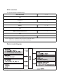
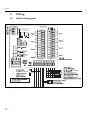
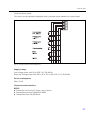
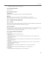
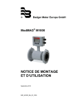
Block circuit diagram
G09-RIA452xx-05-00-xx-en-000
Fig. 1: RIA452 block circuit diagram
Table of contents
1
Safety instructions . . . . . . . . . . 4
10 Technical data. . . . . . . . . . . . . 63
1.1
1.2
1.3
1.4
1.5
Designated use . . . . . . . . . . . . . . . . . . . . . .
Installation, commissioning and operation .
Operational safety . . . . . . . . . . . . . . . . . . .
Return . . . . . . . . . . . . . . . . . . . . . . . . . . . .
Notes on safety conventions and icons . . . .
2
Identification . . . . . . . . . . . . . . 6
10.1
10.2
10.3
10.4
10.5
10.6
10.7
2.1
2.2
2.3
Device designation . . . . . . . . . . . . . . . . . . . 6
Scope of delivery . . . . . . . . . . . . . . . . . . . . 6
Certificates and approvals . . . . . . . . . . . . . . 7
11 Appendix . . . . . . . . . . . . . . . . 75
3
Installation . . . . . . . . . . . . . . . . 8
Index. . . . . . . . . . . . . . . . . . . . 76
3.1
3.2
Installation conditions . . . . . . . . . . . . . . . . 8
Installation instructions . . . . . . . . . . . . . . . 8
4
Wiring . . . . . . . . . . . . . . . . . . 10
4.1
4.2
4.3
Quick wiring guide . . . . . . . . . . . . . . . . . 10
Connecting the device . . . . . . . . . . . . . 14
Post-connection check . . . . . . . . . . . . . . . 16
5
Operation . . . . . . . . . . . . . . . . 17
5.1
5.2
5.3
Quick operation guide . . . . . . . . . . . . . . . 17
Display and operating elements . . . . . . . . 21
Local operation . . . . . . . . . . . . . . . . . . . . 22
6
Commissioning. . . . . . . . . . . . 25
6.1
6.2
6.3
Function check . . . . . . . . . . . . . . . . . . . 25
Switching on the measuring device . . . . 25
Device configuration . . . . . . . . . . . . . . . . 25
7
Maintenance. . . . . . . . . . . . . . 58
8
Accessories. . . . . . . . . . . . . . . 58
9
Troubleshooting . . . . . . . . . . . 59
9.1
9.2
9.3
9.4
9.5
Troubleshooting instructions . . . . . . . . . .
Process error messages . . . . . . . . . . . . . . .
Spare parts . . . . . . . . . . . . . . . . . . . . . . . .
Return . . . . . . . . . . . . . . . . . . . . . . . . . . .
Disposal . . . . . . . . . . . . . . . . . . . . . . . . . .
4
4
4
4
5
59
59
61
62
62
Input . . . . . . . . . . . . . . . . . . . . . . . . . . . .
Output . . . . . . . . . . . . . . . . . . . . . . . . . . .
Installation . . . . . . . . . . . . . . . . . . . . . . . .
Mechanical construction . . . . . . . . . . . . . .
Human interface . . . . . . . . . . . . . . . . . . . .
Certificates and approvals . . . . . . . . . . . . .
Documentation . . . . . . . . . . . . . . . . . . . . .
63
68
69
71
72
73
74
11.1 Flow conversion . . . . . . . . . . . . . . . . . . . . 75
Safety instructions
1
Safety instructions
Safe operation of the process display unit is only guaranteed if these Operating Instructions have
been read and the safety instructions have been observed.
1.1
Designated use
The process display unit analyzes analog process variables and depicts them on its multicolored
display. Processes can be monitored and controlled using analog and digital outputs and limit
relays. The device provides the user with a wide range of software functions for this purpose.
Power can be supplied to 2-wire sensors with the integrated transmitter power supply.
– The device is seen as an associated electrical apparatus and may not be installed in hazardous
areas.
– The manufacturer does not accept liability for damage caused by improper or non-designated
use. The device may not be converted or modified in any way.
– The device is designed for installation in a panel and may only be operated in an installed state.
1.2
Installation, commissioning and operation
This device has been constructed to state-of-the-art technology and meets all applicable
standards and EU directives. The device, however, can be a source of application-related danger
if used improperly or other than intended.
Installation, wiring, commissioning and maintenance of the device must only be carried out by
trained technical personnel. They must have read and understood these Operating Instructions
and must follow the instructions they contain. The information in the electrical wiring diagrams
(see Section 4 'Wiring') must be observed closely.
1.3
Operational safety
Technical improvement
The manufacturer reserves the right to adapt technical details to the most up-to-date technical
developments without any special announcement. Contact your local sales center for
information about the current state of and possible extensions to the Operating Instructions.
1.4
Return
For a return, e.g. in case of repair, the device must be sent in protective packaging. The original
packaging offers the best protection. Repairs must only be carried out by your supplier's service
organization.
!
4
Note!
Please enclose a note describing the fault and the application when sending the unit in for repair.
Safety instructions
1.5
Notes on safety conventions and icons
The safety instructions in these Operating Instructions are labeled with the following safety icons
and symbols:
"
Caution!
This symbol indicates an action or procedure which, if not performed correctly, can result in
incorrect operation or destruction of the device.
#
Warning!
This symbol indicates an action or procedure which, if not performed correctly, can result in
injury, a safety hazard or the destruction of the device.
!
Note!
This symbol indicates an action or procedure which, if not performed correctly, can have an
indirect effect on operation or trigger an unexpected response on the part of the device.
5
Identification
2
Identification
2.1
Device designation
2.1.1 Nameplate
Compare the nameplate on the device with the following diagram:
G09-RIA452xx-18-00-xx-xx-000
Fig. 2: Nameplate of the process display unit (example)
1
2
3
4
5
Order code and serial number of the device
Power supply
Software version number
Ambient temperature
Performance
2.2
Scope of delivery
The scope of delivery of the process display unit comprises:
•
•
•
•
•
!
6
Process display unit for panel mounting
Operating Instructions
CD-ROM with PC configuration software and interface cable RS232 (optional)
Fixing clips
Sealing ring
Note!
Please note the device accessories in Section 8 'Accessories'.
Identification
2.3
Certificates and approvals
CE mark, declaration of conformity
The process display unit is designed to meet state-of-the-art safety requirements, has been tested
and left the factory in a condition in which it is safe to operate. The device meets the relevant
standards and directives as per IEC 61 010-1 "Safety requirements for electrical equipment for
measurement, control and laboratory use".
The device described in these Operating Instructions thus meets the legal requirements of the
EU directives. The manufacturer confirms that the device has been tested successfully by affixing
the CE mark.
7
Installation
3
Installation
3.1
Installation conditions
The permitted ambient conditions (see Section 10 "Technical data") must be observed when
installing and operating. The device must be protected against the effects of heat.
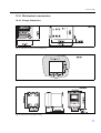
3.1.1 Dimensions
Please note the installation depth of 150 mm (5.91 inches) for the measuring instrument plus
cable. Additional dimensions are provided in Fig. 3 and Section 10 "Technical data".
3.1.2 Mounting location
Installation in panel with 92x92mm (3.62x3.62 inches) cutout (as per EN 60529). The
mounting location must be free from vibrations.
3.1.3 Orientation
Horizontal +/- 45° in every direction.
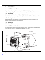
3.2
Installation instructions
The required panel cutout is 92x92 mm (3.62x3.62 inches). Please note the installation depth
of 150 mm (5.91 inches) for the measuring instrument plus cable.
G09-RIA452xx-17-01-06-xx-001
Fig. 3: Installation in panel
8
Installation
1.
Push the device with the sealing ring (item a) through the panel cutout from the front.
2.
Keep the device horizontal and suspend the two fixing clips (item b) in the recesses
provided.
3.
Tighten the screws of the fixing clips evenly with a screwdriver.
4.
Remove the protective strip from the display.
The dimensions of the process display unit are provided in the "Technical data" Section.
9
Wiring
4
Wiring
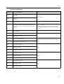
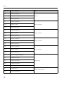
4.1
Quick wiring guide
G09-RIA452ZZ-04-01-xx-en-000
Fig. 4: Terminal assignment of the process display unit (universal input see Page 13)
10
Wiring
Terminal assignment
Terminal
Terminal assignment
L/L+
L for AC
L+ for DC
N/L-
N for AC
L- for DC
NC
Not connected
J1
Jumper for locking device operation via hardware. If
the jumper is set to J1, the configuration cannot be
modified.
J2
Not connected
11
+ 0/4 to 20 mA signal
12
Signal ground (current)
81
24 V sensor power supply 1
82
Ground, sensor power supply 1
41
Normally closed (NC)
42
Common (COM)
43
Normally open (NO)
51
Normally closed (NC)
52
Common (COM)
53
Normally open (NO)
44
Normally closed (NC)
45
Common (COM)
46
Normally open (NO)
Type
Power supply
!
Note!
The measuring instrument can always be configured
with Readwin® 2000 via RS232 even if the jumper is
set to J1.
Current input
Transmitter power supply (optionally intrinsically
safe)
Relay 1
Relay 2
Relay 3
11
Wiring
Terminal
Terminal assignment
54
Normally closed (NC)
55
Common (COM)
56
Normally open (NO)
141
Normally closed (NC)
142
Common (COM)
143
Normally open (NO)
151
Normally closed (NC)
152
Common (COM)
153
Normally open (NO)
144
Normally closed (NC)
145
Common (COM)
146
Normally open (NO)
154
Normally closed (NC)
155
Common (COM)
156
Normally open (NO)
96
Ground for digital status inputs
97
+ digital status input 1
197
+ digital status input 2
297
+ digital status input 3
397
+ digital status input 4
31
+ analog output
32
Ground, analog output
Type
Relay 4
Relay 5 (optional)
Relay 6 (optional)
Relay 7 (optional)
Relay 8 (optional)
Digital inputs
Analog output (optional)
12
Wiring
Terminal
Terminal assignment
33
+ digital output
34
Ground, digital output
91
24 V sensor power supply 2
92
Ground, sensor power supply 2
Type
Digital output (optional)
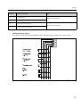
Transmitter power supply
Universal input option
The device can be optionally equipped with a universal input instead of a current input.
G09-RIA452xx-04-10-xx-en-002
Fig. 5: Universal input terminal assignment
13
Wiring
Terminal assignment
Terminal
Terminal assignment
11
+ 0/4 to 20 mA signal
12
Signal ground (current, voltage, temperature)
13
+ 1 V, + thermocouples, - resistance thermometer signal (3/4 wire)
15
+ resistance thermometer signal (4-wire)
17
+ 30 V
19
+ resistance thermometer power supply (3-wire/4-wire)
4.2
"
Connecting the device
Caution!
Do not install or wire the device when it is connected to the power supply. Failure to comply
with this precaution can result in irreparable damage to the electronics.
4.2.1 Connecting the power supply
"
Caution!
• Before wiring the device, ensure that the supply voltage corresponds to the specification on
the nameplate.
• For the 90 to 250 V AC version (power supply connection), a switch marked as a separator,
as well as an overvoltage organ (rated current ≤ 10 A), must be fitted in the supply line near
the device (easy to reach).
G09-RIA452xx-04-10-xx-xx-000
Fig. 6: Connecting the power supply
14
Wiring
4.2.2 Connecting external sensors
!
Note!
Active and passive sensors with analog, TC, resistance and RTD sensors can be attached to the
device.
Depending on the type of signal of the sensor in question, the terminals can be freely selected.
Current input 0/4 to 20 mA
G09-RIA452xx-04-10-xx-en-001
Fig. 7: Connection of the two-wire sensor to the current input 0/4 to 20 mA
Universal input
G09-RIA452xx-04-10-xx-en-003
Fig. 8: Connection of the four-wire sensor, transmitter power supply and universal input
15
Wiring
4.3
Post-connection check
Device condition and specifications
Notes
Is the device or cable damaged (visual inspection)?
-
Electrical connection
Notes
Does the supply voltage match the specifications on the nameplate?
90 to 250 V AC (50/60 Hz)
20 to 36 V DC
20 to 28 V AC (50/60 Hz)
Are all of the terminals firmly engaged in their correct slots? Is the coding on the
individual terminals correct?
-
Are the mounted cables strain relieved?
-
Are the power supply and signal cables correctly connected?
See wiring diagram on the housing
Are all screw terminals firmly tightened?
-
16
Operation
5
Operation
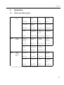
5.1
Quick operation guide
M1
M2
M3
Analog input
INPUT
Display
DISPLAY.
Analog
output*
ANALOG
OUT
Signal type
Connection
type*
Curve
Signal
damping
Signal type
Connection
Curve
Damp
Dimension
Decimal
point
0% value
100% value
Dimension
Dec. point
0% value
100% value
Offset
Comparative
temperature
*
Fixed
comparative
temp.*
Open circuit
detection
Offset
Comp. temp.
Const. temp.
Open circ.
Assign
numerical
display
Alternating
display
Assign
bargraph
Decimal
point
bargraph
Ref. num.
Displ. sw.
Ref. bargraf
Dec. point
Bargraph 0%
value
Bargraph
100% value
Assign
bargraph
Bar 0%
Bar 100%
Ref. bargraf
Assignment
Damping
Output range
Decimal
point
Ref. num.
Out damp
Out range
Dec. point
0% value
100% value
Offset
Output in the
event of a
fault
Out 0%
Out 100%
Offset
Fail mode
*) Only available if the option in question is installed in the device
17
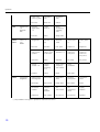
Operation
M5
M10M17
M18
Digital input
1-4
DIGITAL
INP.
Limit 1-4
(8)*
LIMIT
Integration*
Integration
Value in the
event of a fault
Simulation
mA
Simulation
Volt
Fail value
Simu mA
Simu V
Function
digital input
1-4
Active
level1-4
Pump
monitoring
sampling
time
Function
Level
Sampl. time
Assignment
Function 1-4
(8)
Decimal
point
Switch point
A
Switch point
B
Ref. num
Function
Dec. point
Setpoint A
Setpoint B
Hysteresis or
switch- back
gradient
Switching
delay 1-4 (8)
in seconds
Alternate
function 1-4
Delay for 1st
switch-on
every 24 h
Switch-on
period for
switch-on
every 24 h
Hysteresis
Delay
Alternate
Sw. delay
Sw. period
Display
runtime 1-8
Display
switch.
frequency
1-8
Reset switch.
frequency
and runtime
Relay
simulation
Runtime
Count
Reset
Simu relay
Signal source
for integration
Pre-counter
Integration
base
Decimal
point factor
Conversion
factor
Ref. Integr.
Pre-counter
Integr. base
Dec. factor
Factor
Dimension
totalizer
Decimal
point
totalizer
Set
pre-counter
Set
preliminary
alarm
Display
totalizer
Dimension
Dec. point T
Set count A
Set count B
Totalizer
*) Only available if the option in question is installed in the device
18
Operation
M19
Pulse
output*
PULSE OUT
Reset totalizer
Flow
calculation
Dimension of
input signal
Dimension of
linearized
value
Decimal
point for
formula
Reset total
Calc flow
Dim. Input
Dim. flow
Dec. flow
Decimal point
for display
Alpha value
Beta value
Gamma
value
C value
Dec. point
Alpha
Beta
Gamma
C
KhafagiVenturi
channels
Iso-Venturi
channels
Venturi
channels as
per British
Standard
Parshall
channels
ParshallBowlus
channels
Kha Venturi
Iso-Venturi
BST-Venturi
Parshall
Parshall-Bow
Rectangular
weirs
Rectangular
weirs with
constrict-ion
Rectangular
weirs as per
NFX
Rectangular
weirs as per
NFX with
constrict-ion
Trapezoidal
weirs
Rect. WTO
Rect. WThr
NFX Rect.
WTO
NFX Rect.
WThr
Trap. WTO
Triangular
weirs
Triangular
weirs as per
British
Standard
Triangular
weirs as per
NFX
Width
V. weir
BST V. weir
NFX V. weir
width
Decimal point
pulse value
Pulse value
Pulse width
Simulation
pulse output
Dec value
Unit Value
Pulse width
Sim pulseout
*) Only available if the option in question is installed in the device
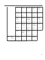
19
Operation
M20
M21
M23Mxx
M55
Min/Max
memory
MIN/MAX
Signal source
for Min/Max
Decimal
point
Display
minimum
value
Ref. min/max
Dec. point
Min. value
Display
maximum
value
Reset
minimum
vaule
Reset
maximum
value
Max. value
Reset min
Reset max
Number of
support points
Dimension of
linearized
value
Decimal
point Y-axis
Delete all
support
points
Display all
support
points
Counts
Dimension
Dec. Y value
Del points
Show points
Lin. support
points
NO 01 NO
32
X-axis
Y-axis
X value
Y value
Operating
parameters
PARAMETE
RS
User code
Limit value
lock
Program
name
Program
version
Pump
alternation
function
User code
Limit lock
Prog. name
Version
Func. alt.
Relay lock
time
Relay failsafe
mode
Time for
gradient
evaluation
Failsafe
mode 4-20
mA input
Error limit 1
Lock time
Rel. Mode
Grad. Time
Namur
Range 1
Error limit 2
Error limit 3
Error limit 4
Display
contrast
Range 2
Range 3
Range 4
Contrast
Linearization
table
LIN-TABLE
M56
SERVICE
Only for service staff. The service code must be entered.
M57
EXIT
Exit the menu. If you have changed parameters, you are asked whether you want to save
the changes.
M58
SAVE
Changes are saved and you exit the menu.
*) Only available if the option in question is installed in the device
20
Operation
5.2
Display and operating elements
G09-RIA452xx-19-00-06-xx-000
Fig. 9: Display and operating elements
1)
2)
3)
4)
5)
6)
7)
8)
9)
Green operating indicator, lights up when supply voltage is applied
Red fault indicator, flashes in event of sensor or device error
Limit value display: if power is supplied to a relay, the symbol is displayed.
Digital input status: green indicates ready for operation, yellow indicates a signal is present
Bar graph yellow, 42-section with orange/red range overshoot and undershoot
7-digit 14-segment display in white for measured values
9x77 DOT matrix in white for text, units and menu icons
Key or lock symbol indicates whether device operation is locked (see Section 5.3.3)
Jog/shuttle dial for local device operation
5.2.1 Display
Range
Display
Relay
Analog output
Integration
Input current is
< lower error limit
Display "
"
Fault condition
Set failsafe mode
No integration
Input current above
lower error limit and
below lower
limitations of validity
Display "
"
Normal limit value
behavior
Normal behavior
with max. 10%
overrange. No
output < 0 mA/0 V
possible
Normal behavior
(negative integration
not possible)
Input current in valid
range
Display scaled
measured value
Normal limit value
behavior
Normal behavior
with max. 10%
overrange. No
output < 0 mA/0 V
possible
Normal behavior
(negative integration
not possible)
21
Operation
Range
Display
Relay
Analog output
Integration
Input current below
upper error limit and
above upper
limitations of validity
Display "
"
Normal limit value
behavior
Normal behavior
with max. 10%
overrange. No
output < 0 mA
possible.
Normal behavior
(negative integration
not possible)
Input current above
upper error limit
Display "
"
Fault condition
Set failsafe mode
No integration
Relay display
No power to relay: no display
Power to relay:
(symbol lit)
Digital input status display
Digital input configured:
(green)
Signal at digital input:
!
(yellow)
Note!
Information on troubleshooting can be found in Sections 9.1 and 9.2 of these Operating
Instructions.
5.3
Local operation
Operating menu activated by pressing the jog/shuttle dial for 3 seconds at least.
5.3.1 Operation via the jog/shuttle dial
A) E+H 3-key function
• Press = "Enter"
• Rotate in clockwise direction = "+"
• Rotate in counterclockwise direction = "-"
G09-RIA452ZZ-19-00-00-xx-002
Fig. 10: Operation via jog/shuttle dial
22
Operation
B) Selection from list
Æ Arrow pointing down:
Option is at the top of the picklist. The other entries become
visible when the jog/shuttle is turned in the clockwise direction.
Å Both arrows visible:
Æ User is in the middle of the picklist.
Å Arrow pointing up:
The end of the picklist is reached. The user moves back towards
the start when the jog/shuttle is turned in the counterclockwise
direction.
G09-RIA452ZZ-19-00-00-xx-003
Fig. 11: Selecting from list via jog/shuttle dial
5.3.2 Entering text
G09-RIA452ZZ-19-00-00-en-001
Fig. 12: Entering text with RIA452
Item No.
Description
1
Activate the operating menu by pressing the jog/shuttle dial for at least 3 seconds. The first character then
starts flashing.
2
You can change the flashing (selected) character by turning the jog/shuttle dial (see "Possible characters").
You can go back to the previous character by selecting the back symbol (arrow to left).
3
Press the jog/shuttle dial to select the selected character and to switch to the next character (in our
example, the second character is now flashing).
4
Press the jog/shuttle dial briefly for the last character to accept the entry.
5
Press the jog/shuttle dial for longer than 1 second (max. 2 seconds) to reject the entry at the point in
question.
23
Operation
Possible characters
The following characters can be entered:
Space
+ABCDEFGHIJKLMNOPQRSTUVWXYZabcdefghijklmnopqrstuvwxyz0123456789/\%°23+-.;
:*() followed by return symbol (arrow to left)
5.3.3 Disabling the programming mode
User code
The configuration can be protected against unintentional access by means of a four-digit code.
This code is defined in the submenu "Parameter/User Code". All the parameters remain visible
on the display but the "key" symbol is shown on the display. If you then want to change a
parameter, you first have to set the valid user code.
Hardware locking
In addition, configuration can also be locked using a connector on the rear of RIA452 (see
drawing). This is indicated by the "padlock" symbol on the display.
To hardware-lock the measuring instrument, insert the jumper into position J1 in the top
right-hand corner on the rear of the instrument.
G09-RIA452ZZ-19-00-00-xx-004
Fig. 13: Position of the jumper on the rear of the instrument
!
24
Note!
Hardware locking has no effect on the PC operating software Readwin® 2000.
Commissioning
6
Commissioning
6.1
Function check
Make sure that all post-connection checks have been carried out before you commission your
device:
• Checklist Section 4.3 'Post-connection check'
!
Note!
Remove the protective strip from the display as this restricts display legibility otherwise.
6.2
Switching on the measuring device
Once the operating voltage is applied, the green LED indicates that the instrument is operational.
• When the unit is delivered, the device parameters are used as per the factory settings.
• When commissioning a device already configured or preset, measuring is immediately started
as per the settings. The limit values only switch once the first measured value has been
determined.
• The limit values are only activated as per their configuration once a valid measured value is
present.
6.3
Device configuration
This section describes all the configurable instrument parameters with the associated value
ranges and factory settings (default values, marked in bold).
6.3.1 Analog input - INPUT/M1
All the parameters that can be selected for the input can be found under the analog input menu
item which is marked as INPUT in the device.
25
Commissioning
Function
(menu
item)
Parameter setting
Description
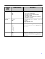
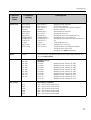
Signal type
4 - 20 mA
0 - 20 mA
0 - 5 mA (*)
0 - 100 mV (*)
0 - 200 mV (*)
0 - 1 V (*)
0 - 10 V (*)
± 150 mV (*)
± 1 V (*)
± 10 V (*)
± 30 V (*)
Type B (IEC584) (*)
Type J (IEC584) (*)
Type K (IEC584) (*)
Type L (DIN43710) (*)
Type L (GOST) (*)
Type N (IEC584) (*)
Type R (IEC584) (*)
Type S (IEC584) (*)
Type T (IEC584) (*)
Type U (DIN43710) (*)
Type D (ASTME998) (*)
Type C (ASTME998) (*)
PT50 (GOST) (*)
PT100 (IEC751) (*)
PT100 (JIS1604) (*)
PT100 (GOST) (*)
PT500 (IEC751) (*)
PT500 (JIS1604) (*)
PT500 (GOST) (*)
PT1000 (IEC751) (*)
PT1000 (JIS1604) (*)
PT1000 (GOST) (*)
Cu50 (GOST) (*)
Cu100 (GOST) (*)
30 - 3000 Ohm (*)
Selects the signal type of the connected sensor.
Parameters marked with an asterisk (*) can only be
selected with the universal input option.
Connection
3 Wire
4 Wire
Configures the sensor connection in 3-wire or 4-wire
technology. Can only be selected for "Signal type"
30-3000 Ω, PT50/100/1000, Cu50/100
26
Commissioning
Function
(menu
item)
Parameter setting
Description
Curve
Linear
Quad.
°C
°F
Kelvin
Linear or quadratic (quad.) characteristic of the sensor
used. Can be selected for analog signals. °C, °F, Kelvin
physical measured variable, can be selected for
temperature sensors.
Damp
0..99.9
0
Signal damping of measuring input with 1st order low
pass. Time constant can be selected from 0 to 99.9 sec.
Dimension
XXXXXXXXX
%
The technical unit or an arbitrary text for the measured
value of the sensor can be configured here. Max. length
9 characters.
Dec. point
XXXXX
XXXX.X
XXX.XX
XX.XXX
X.XXXX
Number of places after the decimal point for displaying
the measured value.
0% value
-99999..99999
0
Start value of measured value, can be selected for
analog signal types
100% value
-99999..99999
100.0
End value of measured value, can be selected for analog
signal types
Offset
-99999..99999
0.0
Shifts the zero point of the response curve. This
function is used to adjust the sensor.
Comp. temp
Intern
const
Comparative temperature for thermocouple
measurement. An internal cold junction (= Intern) or a
constant value (= const) can be selected.
Const. temp
9999.9
20.0
Fixed comparative temperature.
This can only be selected if const is set for "Cmp.
Temp".
Open circ.
No
Yes
Switch cable open circuit detection for thermocouples
off or on
27
Commissioning
Adjusting the analog input
The input can be adjusted to the sensor with the aid of the following parameters.
For current, voltage and resistance sensors, a scaled value is calculated from the sensor signal:
For temperature outputs, the scaled value is calculated from linearization tables. The
temperature value can be converted to degrees Celsius, degrees Fahrenheit or Kelvin. In
addition, the temperature value can be corrected by means of an offset.
!
Note!
The signal types 4 to 20 mA, thermocouples and resistance thermometers are monitored for
cable open circuit. In the case of resistance thermometers, long reaction times can occur.
6.3.2 Display - DISPLAY/M2
All the settings for the device display are grouped under this menu item.
Function
(menu
item)
Ref. num.
Parameter setting
Input
Lin. table
Total (*)
Inp.+Lint.
Inp.+Tot. (*)
Lint.+Tot. (*)
In+Lin+Tot (*)
Batch (*)
Description
For choosing the display value on the display.
(If a combination is selected, e.g. "Inp.+Lint", the
display alternates between the selected display values,
e.g. measured value (Inp.) and linearized measured
value (Lint.))
• Input = measured value
• Lin. table = linearized measured value or current
flow value for channel calculation
• Total = integrated value
• Inp.+Lint. = alternates between measured value and
linearized measured value
• Inp.+Tot. = alternates between measured value and
integrated value
• Lint.+Tot. = alternates between linearized
measured value and integrated value
• In+Lin+Tot = measured value, linearized measured
value or integrated value
• Batch = preset counter
Settings marked with an asterisk (*) can only be
selected if the pulse output or integration option is
available and has been configured.
28
Commissioning
Function
(menu
item)
Parameter setting
Description
Display sw.
0 to 99 sec
0
Selectable period for displaying the individual values if
combinations of display values have been selected
under Ref. num.
This setting can only be selected if the pulse output or
integration option is available and has been configured.
Ref. bargraf
Input
Lintab
Selects the signal source for the bar graph
Dec. point
XXXXX
XXXX.X
XXX.XX
XX.XXX
X.XXXX
Number of digits after the decimal point for bar graph
scaling.
Bar 0%
-99999..99999
0.0
Start value for the bar graph
Bar 100%
-99999..99999
100.0
End value for the bar graph
Bar rise
Right
Left
Bar graph orientation.
• Right = 100% value (rising from left to right)
• Left = 100% value left (falling from left to right)
29
Commissioning
6.3.3 Analog output - ANALOG OUT/M3
All configurable parameters for the analog output can be found under the analog output menu
item which is marked as ANALOG OUT in the device.
!
Note!
This item is only available if the "Analog output" option is available in your device.
Function
(menu
item)
Parameter setting
Description
Ref. num.
Input
Lintab
Selects which value is output at the analog output.
• Input = measured value
• Lintab = linearized measured value or current flow
value for channel calculation
Out damp
0..99.9
0.0
Signal damping of measuring input with 1st order low
pass. Time constant can be selected from 0 to 99.9 sec.
Out range
Off
0 - 20 mA
4 - 20 mA
0 - 10 V
2 - 10 V
0-1V
Signal type of output
Dec. point
XXXXX
XXXX.X
XXX.XX
XX.XXX
X.XXXX
Number of places after the decimal point for outputting
the measured value. Can be selected for analog signal
types
Out 0%
-99999..99999
0.0
Start value of the output signal
Out 100%
-99999..99999
100.0
End value of the output signal
Offset
-999.99..999.99
0.00
Shifts the zero point of the output curve in mA or V.
30
! Note!
"Off" switches the output signal off completely.
Commissioning
Function
(menu
item)
Parameter setting
Description
Fail mode
Hold
const
Min
Max
Output value if a sensor or device error occurs.
• Hold = last valid value
• Const = freely selectable value
• Min = output value 3.5 mA for 4 to 20 mA,
otherwise 0 V or 0 mA
• Max = output value 22.0 mA for 0/4 to 20 mA,
otherwise 1.1 V or 11 V
Fail value
0..999.99
0.00
The freely selectable value for "Fail mode = Const" can
be set here.
Current output: 0 to 22 mA
Voltage output: 0 to 11 V
Simu mA
OFF
0.0 mA
3.6 mA
4 mA
10 mA
12 mA
20 mA
21 mA
Simulates the current output and outputs the selected
current at the output, regardless of the input value.
Is automatically set to OFF when the Simu mA menu
item is exited.
Simu V
OFF
0.0 V
5.0 V
10.0 V
Simulates the voltage output and outputs the selected
voltage at the output, regardless of the input value.
Is automatically set to OFF when the Simu V menu
item is exited.
31
Commissioning
6.3.4 Digital input - DIGITAL INP./M5
The settings for the digital status inputs, e.g. for monitoring pumps, starting/stopping the
counter or resetting the min/max-value memory are grouped in this section.
!
Note!
– The digital inputs 1 to 4 are permanently assigned to relays 1 to 4 in the PUMP function.
Relay 1 is monitored by digital input 1, relay 2 by digital input 2 etc.
– When the "Batch" function is used, digital input 1 is permanently assigned to a preset value
count function. Configuration for this digital input is then not possible.
Function
(menu
item)
Function
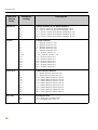
Parameter setting
Off
Pump
Res Tot. (*)
Start/Stop (*)
Res MinMax
Description
Function of the selected digital input.
• Off
• Pump = pump monitoring (see Pump monitoring
function)
• Res Tot. = reset the totalizer*
• Start/Stop = start or stop the totalizer*
• Res MinMax = reset the min/max memory values
! Note!
Parameters marked with an asterisk (*) are only
available for the pulse output option if this function has
been configured.
Level
Low
High
Selects the side for evaluation.
• Low = descending side
• High = increasing side
Sampl. time
0..99
0
Defines the time (in seconds) within which pump
feedback at the digital input is to be expected. If there
is no feedback within the defined time, an error
message is generated and a second pump is activated if
more than one pump is available.
! Note!
The sampl. time setting is used to specify the
monitoring behavior of the digital input!
Sampl. time = 0 means fault monitoring
Sampl. time <> 0 means operation monitoring
32
Commissioning
Pump monitoring function
If pump monitoring should be implemented, digital inputs 1 to 4 are permanently assigned to
relays 1 to 4. This function is enabled for the corresponding digital input with the Function
parameter. Pump must be selected here.
In general, two different types of monitoring can be implemented. With fault monitoring, the
signal at the digital input is changed if there is a fault at the pump.
With operation monitoring, the correct startup and operation of the pump is reported to the
process display unit by means of a signal change at the digital input.
The Sampl. Time setting is used to choose between these operating modes.
Setting
• Sampl. Time = 0 -> fault monitoring
• Sampl. Time <> 0 -> operation monitoring
a) Fault monitoring operating mode
In the fault monitoring operating mode, the status signal signals the availability of the pump. If
a fault occurs, the status signal changes accordingly.
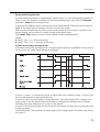
G09-RIA452ZZ-16-10-xx-en-006
Fig. 14: Fault monitoring operating mode
In event 1, pump 1 is activated as a result of signal limit value violation. Pump 1 is active until
the level has dropped an appropriate amount.
In event 2, a fault occurs at pump 1 during operation. The status signal at DI1 changes. As a
result, pump 2 and the alarm relay are activated (if configured accordingly) and a message
indicating the pump malfunction is shown on the display.
In event 3, the level has dropped to the extent that the system no longer has to pump and pump
2 stops operating.
The fault at pump 1 was rectified, the status signal at DI1 changes again. The alarm relay is reset,
see event 4.
33
Commissioning
In event 5, the alarm relay and the error message on the display are acknowledged by pressing
the jog shuttle.
In event 6 and 7, the unproblematic operation of the system is indicated.
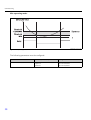
b) Operation monitoring
In the operation monitoring mode, a change in the status signal is expected at the related digital
input once a pump has been triggered. A waiting time (Sampl. Time, T) is defined for this. The
alternating system is activated. If no signal change is experienced during the specified time, the
pump is regarded as faulty.
G09-RIA452ZZ-16-10-xx-en-007
In event 1, the unproblematic operation of pump 1 is illustrated. Pump 1 is activated following
triggering due to limit value violation. The status signal changing within T at DI1 signals an
unproblematic pump. The pumping sequence continues with pump 1.
In event 2, no checkback signal follows at DI1 once pump 1 has been activated. Thus, this pump
is regarded as faulty. The alarm relay is activated and an error message is output on the display.
The pumping action is assumed by pump 2, event 3. This pump reports back to DI2 within the
defined waiting time. Pumping continues until the limit value violation is undershot.
In event 4, a new limit value violation occurs. Due to the alternating system, another attempt is
made to start pump 1. Since again no checkback signal is returned by the time the waiting time
has elapsed, pump 2 (event 5) takes over operation. If the alarm relay and error message were
not already active on the display, they would be now.
In event 6, the level is exceeded again and a pump is activated. Following the alternating system,
pump 1 is tried again. This time, pump 1 returns a checkback signal. The alarm relay is reset.
In event 7, the error message on the display is acknowledged. The status signal at the DI does
not have any effect on error message acknowledgment on the display.
34
Commissioning
!
Note!
A faulty pump is always brought back into service depending on the signal at the related digital
input. Acknowledging the error message on the display does not have any effect on the pump
going back into operation.
If a pump is faulty for longer than 10 minutes, an attempt is made to bring the pump back into
operation upon the next limit violation.
The following parameters must be configured:
Menu
Function (menu item)
Setting value
DIGITAL INP./M5
Function
Level
Sampl. time
Pump
Low or High
Sampling time in seconds
LIMIT 1 to 8
Alternate
Yes
6.3.5 Limit values - LIMIT 1 to 8/M10 to 17
!
Note!
If the "Batch" function is used, limit values 1 and 2 are permanently assigned activation in the
event of a "preset counter" and "preliminary alarm" limit value. These limit values cannot be
configured. They are not shown in the menu structure.
Function
(menu
item)
Ref. num.
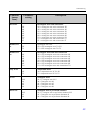
Parameter setting
Input
Lin. table
Description
Selects which value is used:
• Input: scaled value from analog input
• Lin. table: value from linearization table or current
flow value for channel calculation
35
Commissioning
Function
(menu
item)
Parameter setting
Description
Function
Off
Min
Max
Grad
In band
Out band
Alarm
Alarm inverse
Selects limit value and fault monitoring. In the event of
device errors or incorrect input values (see error limits
Range 1 to 4 in Section 6.3.11), the relays are
switched in accordance with the failsafe mode
configured in Rel. Mode (see Section 6.3.11).
• Min: minimum with hysteresis (see Page 38)
• Max: maximum with hysteresis (see Page 39)
• Grad: gradient (see Page 40)
• In band: validity range within two values
• Out band: validity range outside of two values
• Alarm: relay is used as an alarm relay
• Alarm inverse: Relay is used as an alarm relay; the
switching behaviour of the relay is safety-oriented
such that the relay drops out in the case of a power
supply failure or a device malfunction.
Dec. point
XXXXX
XXXX.X
XXX.XX
XX.XXX
X.XXXX
Number of digits after the decimal point for the limit
value.
Setpoint A
-99999 to 99999
0.0
Measured value at which a change in the switch status
occurs (slope for gradient). Default: 0.0
Setpoint B
-99999 to 99999
99999
The second setpoint can be configured for the "In band"
and "Out band" operating modes and is only visible if
one of these two functions was selected for this relay.
Hysteresis
-99999 to 99999
99999
For entering the hysteresis for the threshold at
minimum/maximum as an absolute value.
Delay
0 to 99
0
Sets the limit value event delay once the threshold is
reached (in seconds) (see Page 41).
Alternate
No
Yes
Determines the switching function for this relay:
• No: no alternating function; switch point
permanently assigned to relay
• Yes: alternate function (see Page 42)
! Note!
Relays 1-4 can be used for the alternating function.
36
Commissioning
Function
(menu
item)
Parameter setting
Description
Sw. delay
0..99
0
The starting time for 24-hour counting can be selected
with Sw. delay. Every time the instrument is reset, the
process of measuring 24 hours and the delay time is
restarted.
Example see Page 43
Sw. period
0..999
0
Limit value is activated cyclically every 24 hours for 0
to 999 seconds. The activation is delayed by [Sw.delay]
hours by changing the hour value (example
see Page 43).
Runtime
Displays the run time of the connected device, e.g.
pump, in hours [h].
Count
Records the switching frequency of the limit value.
Reset
No
Yes
Resets the run time and switching frequency for this
limit value.
Simu relay
Off
Low
High
Simulation of the selected limit value. Is automatically
set to Off when the menu item is exited.
37
Commissioning
Min operating mode
G09-RIA452ZZ-15-00-xx-en-001
Fig. 15: Min operating mode
The following parameters must be configured:
38
Menu
Function (menu item)
Setting value
LIMIT 1 to 8/M10 to 17
Function
Setpoint A
Hysteresis
Min
Value for threshold
Value for hysteresis
Commissioning
Max operating mode
G09-RIA452ZZ-15-00-xx-en-002
Fig. 16: Max operating mode
The following parameters must be configured:
Menu
Function (menu item)
Setting value
LIMIT 1 to 8/M10 to 17
Function
Setpoint A
Hysteresis
Max
Value for threshold
Value for hysteresis
39
Commissioning
Grad operating mode
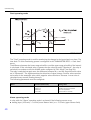
G09-RIA452ZZ-15-00-xx-en-006
Fig. 17: Grad operating mode
The "Grad" operating mode is used for monitoring the changes in the input signal over time. The
time basis Tm of the monitoring system is configured in the "PARAMETER/M55 -> Grad. time"
menu.
The difference between the lower range value M0-m and the upper range value M0 of the interval
is calculated. If the calculated value is greater that the value set under "Setpoint A", the relay is
switched in accordance with the failsafe mode configured in "Rel. Mode" (see Page 56).
The relay is switched on again once the difference between M1-m and M1 drops below the value
set in "Hysteresis". The sign determines the direction of signal change. Positive values monitor
an increase in the measured value while negative values monitor a decrease. A new value is
calculated every second (floating interval).
The following parameters must be configured:
Menu
Function (menu item)
Setting value
LIMIT 1 to 8/M10 to 17
Function
Setpoint A
Hysteresis
Grad. time
Grad
Gradient value for threshold
Value for hysteresis
Interval time in seconds
Alarm operating mode
A relay with the "Alarm" operating mode is activated if the following events occur:
• Analog input (4-20 mA) < 3.6 mA (lower Namur limit) or > 21.0 mA (upper Namur limit)
40
Commissioning
• EEPROM HW error (E101)
The relay remains picked up even after acknowledging.
• Implausible calibration data (E103)
The relay remains picked up even after acknowledging.
• Bus error reading the min/max data after power-up (E104)
The relay remains picked up even after acknowledging.
• Bus error reading the relay data after power-up (E105)
The relay remains picked up even after acknowledging.
• Universal card HW error (E106)
The relay remains picked up even after acknowledging.
• Pulse buffer overflow (E210)
The relay drops out after acknowledging.
• Pump error at the digital input x in question (E22x)
The relay remains picked up even after acknowledging.
Delay
G09-RIA452ZZ-15-00-xx-en-003
Fig. 18: Delay
The following parameters must be configured:
Menu
Function (menu item)
Setting value
LIMIT 1 to 8/M10 to 17
Setpoint A
Hysteresis
Delay
Value for threshold
Value for hysteresis
Delay time in [s]
41
Commissioning
Alternate
Measured value
Mode Max
Setpoint A 3
Setpoint A 3
- Hysterese 3
Setpoint A 2
Setpoint A 2
- Hysterese 2
Setpoint A 1
Setpoint A 1
- Hysterese 1
t
Switching status
With alternating pump control
Relay 3
Relay 2
Relay 1
t
Switching status
Relay 3
Without alternating pump control
Relay 2
Relay 1
t
Relay currentless
G09-RIA452ZZ-15-00-xx-en-007
Fig. 19: Alternating pump control
Alternate switching is used to ensure that several pumps are utilized evenly in level control
systems. The main factor for switching on a certain pump is not a fixed assigned switch-on value
but rather which pump has the shortest operation time.
In total, the first 4 relays (LIMIT 1 to 4) can be included in the alternating pump control system.
42
Commissioning
!
Note!
Relays not included in alternating pump control are available.
This function cannot be applied to individual relays. Relays not included are not assessed based
on the switch-on and switch-off duration.
The following parameters must be configured for the example above:
Menu
Function (menu item)
Setting value
LIMIT 1 to 3/M10 to 12
Each: setpoint A
Each: hysteresis
Each: alternate
Value for threshold
Value for hysteresis
Yes
24-hour activation function
Pumps with long downtimes can be activated cyclically with the 24-hour activation function for
the time (0 to 999 sec) defined in Sw. period.
The starting time for the 24-hour step interval can be postponed by 0 to 23 hours with the Sw.
delay setting.
G09-RIA452ZZ-15-00-xx-en-009
Fig. 20: 24-hour activation function
Example: time at the time of configuration 12 midday, desired start of 24-hour counting 22:00
(10 p.m.) set Sw. delay to 10.
!
Note!
If power is switched off, the time for the 24-hour activation function starts again.
The following parameters must be configured for the example above:
Menu
Function (menu item)
Setting value
LIMIT
Sw. period
Sw. delay
Activation duration
Activation delay
43
Commissioning
6.3.6 INTEGRATION/M18
This function can only be selected if the pulse output option is available in the device.
!
Note!
If the preset counter function (Batch) is used, digital input 1 and relay 1 and 2 are permanently
assigned to this function. Configuration for these inputs/outputs is then not possible.
Function
(menu
item)
Parameter
setting
Description
Ref. integr.
Input
Lintab
Selects which value should be integrated.
• Input = measured value
• Lintab = linearized measured value or current flow value for
channel calculation
Pre-counter
Off
Count up
Count down
Activation of the preset counter
Off = preset counter off
Count up = counting up from zero to the end value
Count down = counting down from the start value to zero
Integr. base
Off
sec
Min
hour
day
Time basis for integration
Dec. factor
XXXXX
XXXX.X
XXX.XX
XX.XXX
X.XXXX
Decimal point position of the conversion factor
Factor
0..99999
1.0
Conversion factor
Dimension
XXXXXXXXX
Select the dimension from the list or dimension as free text (max. 9
characters long).
Dec. point T
XXXXX
XXXX.X
XXX.XX
XX.XXX
X.XXXX
Decimal point of totalizer
44
Commissioning
Function
(menu
item)
Parameter
setting
Description
Set count A
999999
0.0
End value/start value for preset counter; refers permanently to relay 1.
Set count B
999999
0.0
Value for preliminary alarm; refers permanently to relay 2.
Totalizer
9999999
In this position, the totalizer can be displayed and edited (e.g. assigned
a default value).
! Note!
The counter starts again at 0 if the maximum value of 9999999 is
exceeded.
Reset total
Calc. flow
No
Yes
No
Curve
Formula
Reset totalizer
!
Note!
Cannot be configured via ReadWin® 2000.
For selecting a method of calculating the total flow based on the
channel type or by means of a formula using the analog input signal
(e.g. level signal)
• No = no integration
• Curve = flow calculated with channel type.
If "Curve" is selected, the menu only displays possible channel types
for configuration (e.g. Venturi channels, Parshall channels, weirs
etc.)
• Formula = flow calculated using a formula
If "Formula" is selected, the menu only displays possible
configuration parameters for entering the formula (Alpha, Beta,
Gamma, C).
Here, the flow is calculated using the following formula:
Dim. input
mm
inch
Dimension of the channel size
Dec. flow
XXXXX
XXXX.X
XXX.XX
XX.XXX
X.XXXX
Decimal point for display
45
Commissioning
Function
(menu
item)
Parameter
setting
Description
m3/s, l/s, hl/s,
igal/s, usgal/s,
barrels/s, inch3/s,
ft3/s, Usmgal/s,
Ml/s, m3/smin,
l/min, hl/min,
igal/min,
usgal/min,
barrels/min,
inch3/min,
ft3/min,
Usmgal/min,
Ml/min, m3/h,
l/h, hl/h, igal/h,
usgal/h,
barrels/h,
inch3/h, ft3/h,
Usmgal/h, Ml/h
Dimension of linearized value
• l = liter
• hl = hectoliter
• m3 = cubic meter
• Ml = megaliter
• USgal = US gallon
• USKgal = US kilogallon
• USMgal = US megagallon
Dec. point
XXXXX
XXXX.X
XXX.XX
XX.XXX
X.XXXX
Decimal point for formula
(only if formula-based flow calculation is selected)
Alpha
-99.99999
Flow rate exponent α (see Calc.flow)
Beta
-99.99999
Flow rate exponent β (see Calc.flow)
Gamma
-99.99999
Weighting factor
C
-100
Scaling constant C (see Calc.flow)
Dim. flow
46
•
•
•
•
•
USbl = US barrel
igal = imperial gallon
ibl = imperial barrel
inch = inch
ft = feet
1 hl = 100 l
1 m3 = 1,000 l
1 Ml = 1,000,000 l
1 USgal = 3.79 l
1 USKgal = 3,785.41 l
1 USMgal =
3,785,411.78 l
1 USbl = 119.24 l
1 igal = 4.55 l
1 ibl = 163.66 l
1 inch = 25.4 mm
1 ft = 304.8 mm
Commissioning
Function
(menu
item)
Parameter
setting
Description
Khafagi-Venturi channels
ISO-Venturi channels
Venturi channels as per British Standard
Parshall channels
Parshall-Bowlus channels
Rectangular weir (w)
Rectangular weir with constriction (w)
Rectangular weir as per NFX (w)
Rectangular weir as per NFX with constriction
(w)
Trapezoidal weir (w)
Triangular ("V") weir (w)
Triangular weir as per British Standard
Triangular weir as per NFX
Configure (w) width additionally
Flumes weir
Kha Venturi
ISO Venturi
BST Venturi
Parshall
Palmer-Bow
Rect. WTO
Rect WThr
NFXRectWTO
NFXRectWThr
Trap.W TO
V-weir
BST V-weir
NFX V-weir
Kha-Venturi =
ISO Venturi =
BST Venturi =
Parshall =
Palmer-Bow =
Rect. WTO =
Rect WThr =
NFXRectWTO =
NFXRectWThr =
Trap.WTO =
V-weir =
BST V-weir =
NFX V-weir =
Width
99999
Value for width. Can only be selected for channel types marked with
(w) (see Flumes-Weir)
Kha-Venturi
QV 302
QV 303
QV 304
QV 305
QV 306
QV 308
QV 310
QV 313
QV 316
ISO Venturi
415
425
430
440
450
480
Khafagi-Venturi
channels
QV 302 =
QV 303 =
QV 304 =
QV 305 =
QV 306 =
QV 308 =
QV 310 =
QV 313 =
QV 316 =
Khafagi-Venturi channel QV 302
Khafagi-Venturi channel QV 303
Khafagi-Venturi channel QV 304
Khafagi-Venturi channel QV 305
Khafagi-Venturi channel QV 306
Khafagi-Venturi channel QV 308
Khafagi-Venturi channel QV 310
Khafagi-Venturi channel QV 313
Khafagi-Venturi channel QV 316
ISO-Venturi channels
415 = ISO-Venturi channel 415
425 = ISO-Venturi channel 425
430 = ISO-Venturi channel 430
440 = ISO-Venturi channel 440
450 = ISO-Venturi channel 450
480 = ISO-Venturi channel 480
47
Commissioning
Function
(menu
item)
Parameter
setting
4"
7"
12"
18"
30"
Venturi channels as per British Standard
4" = Venturi channel as per British Standard 4 inch
7" = Venturi channel as per British Standard 7 inch
12" = Venturi channel as per British Standard 12 inch
18" = Venturi channel as per British Standard 18 inch
30" = Venturi channel as per British Standard 30 inch
1"
2"
3"
6"
9"
1 ft
1.5 ft
2 ft
3 ft
4 ft
5 ft
6 ft
8 ft
Parshall channels
1" = Parshall channel 1 inch
2" = Parshall channel 2 inch
3" = Parshall channel 3 inch
6" = Parshall channel 6 inch
9" = Parshall channel 9 inch
1 ft = Parshall channel 1 ft
1.5 ft = Parshall channel 1.5 ft
2 ft = Parshall channel 2 ft
3 ft = Parshall channel 3 ft
4 ft = Parshall channel 4 ft
5 ft = Parshall channel 5 ft
6 ft = Parshall channel 6 ft
8 ft = Parshall channel 8 ft
6"
8"
10"
12"
15"
18"
21"
24"
27"
30"
Palmer-Bowlus channels
6" = Palmer-Bowlus channel 6 inch
8" = Palmer-Bowlus channel 8 inch
10" = Palmer-Bowlus channel 10 inch
12" = Palmer-Bowlus channel 12 inch
15" = Palmer-Bowlus channel 15 inch
18" = Palmer-Bowlus channel 18 inch
21" = Palmer-Bowlus channel 21 inch
24" = Palmer-Bowlus channel 24 inch
27" = Palmer-Bowlus channel 27 inch
30" = Palmer-Bowlus channel 30 inch
5H
T5
Rectangular weir
5H = rectangular weir WTO/5H
T5= rectangular weir WTO/T5
BST Venturi
Parshall
Palmer-Bow.
Rect.WTO
48
Description
Commissioning
Function
(menu
item)
Parameter
setting
2H
3H
4H
5H
6H
8H
TO
T5
2T
Rectangular weir with constriction
2H = rectangular weir with constriction 2H
3H = rectangular weir with constriction 3H
4H = rectangular weir with constriction 4H
5H = rectangular weir with constriction 5H
6H = rectangular weir with constriction 6H
8H = rectangular weir with constriction 8H
TO = rectangular weir with constriction TO
T5 = rectangular weir with constriction T5
2T = rectangular weir with constriction 2T
5H
T5
Rectangular weir NFX
5H = NFX rectangular weir TO/5H
T5 = NFX rectangular weir TO/T5
2H
3H
4H
5H
6H
8H
TO
Rectangular weir NFX with constriction
2H = NFX rectangular weir with constriction 2H
3H = NFX rectangular weir with constriction 3H
4H = NFX rectangular weir with constriction 4H
5H = NFX rectangular weir with constriction 5H
6H = NFX rectangular weir with constriction 6H
8H = NFX rectangular weir with constriction 8H
TO = NFX rectangular weir with constriction TO
3H
T5
Trapezoidal weirs
3H = trapezoidal weir W TO/3H
T5 = trapezoidal weir W TO/T5
22.5
30
45
60
90
Triangular weirs
22.5 = Triangular weir 22.5
30 = Triangular weir 30
45 = Triangular weir 45
60 = Triangular weir 60
90 = Triangular weir 90
22.5
45
90
Triangular weir as per British Standard
22.5 = Triangular weir as per British Standard 22.5
45 = Triangular weir as per British Standard 45
90 = Triangular weir as per British Standard 90
Rect.WThr
NFXRect.WT
O
NFXRect.WT
hr
Description
Trap. W TO
V-weir
BST V-weir
49
Commissioning
Function
(menu
item)
Parameter
setting
NFX V-weir
30
45
60
90
Description
NFX triangular weir
30 = NFX triangular weir 30
45 = NFX triangular weir 45
60 = NFX triangular weir 60
90 = NFX triangular weir 90
Integration function
With this function, the computed value from the linearization table or the current flow value for
channel calculation, or that of the analog input can be numerically integrated to create a totalizer
for example.
The totalizer is calculated as follows:
The measuring interval is 0.1 s.
In most instances, the integration basis is the same time unit as the time basis of the signal to be
integrated.
Example: analog input l/s integration basis s
Simple preset counter
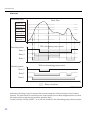
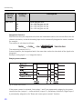
G09-RIA452ZZ-15-00-xx-en-010
Fig. 21: Simple preset counter
If the preset counter is activated, limit values 1 and 2 are permanently assigned to the preset
counter function (output 1 = main switchoff, output 2 = preliminary switchoff). Digital input 1
is permanently assigned to the "Reset and restart preset counter" function.
50
Commissioning
Thus, the number of free relays available is reduced accordingly. The operating menus for these
inputs/outputs are then hidden.
Set count B (LV B) defines the preliminary switchoff, Set count A (LV A) defines the main
switchoff. Limit value (or start value, see "Pre-counter" function on Page 44) for LV A and
preliminary alarm value for LV B are freely configurable
The positive counting direction is defined as follows: starting at the fixed starting value of zero,
count up until the set limit value is reached (Set count A).
The negative counting direction is defined as follows: starting at the configurable starting value
(Set count A), count down until the fixed limit value of zero is reached.
Resetting with simultaneous counter restart takes place by means of digital input 1 (Digital
Inp.1). Edge Digital Inp.1: Low-High = reset and start counter.
!
Note!
Display of the preset counter can be selected under DISPLAY/M2 É "Ref. num" = "Batch"
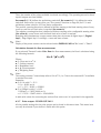
Calculation formula for flow measurement
If you selected "Formula" under Calc. flow for flow measurement, the flow is calculated using
the following formula:
Where:
• Q: Flow rate in m3/h
• C: Scaling constant
• h: Headwater level
• α, β: Flow exponent
• γ: Weighting factor
!
Note!
The scaling constant C must always refer to Q in m3/h, i.e. C has to be converted if C is available
in another flow unit.
Examples:
• Q in l/h with C = 2.11
1 l/h = 0.001 m3/h
C = 2.11 * 0.001 = 0.00211
• Q in USKgal/s with C = 0.35
1 USKgal/s = 13627.4444 m3/h
C = 0.35 * 13627.4444 = 4769.60554
A table with values for converting the various flow units to m3/h is provided in the appendix.
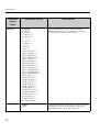
6.3.7 Pulse output - PULSE OUT/M19
All the possible settings for the pulse output can be found in this menu item. This menu item
can only be selected if your device is fitted with this option.
51
Commissioning
Function
(menu
item)
Parameter setting
Description
Dec. value
XXXXX
XXXX.X
XXX.XX
XX.XXX
X.XXXX
Decimal point position of the pulse value.
Unit value
0..99999
1.0
Pulse value with which the pulses should be output at
the output.
Pulse width
0.04 to 2000ms
1000.00
Sets the pulse width at the pulse output.
Off
1 Hz
10 Hz
100 Hz
1000 Hz
10000 Hz
Outputs the selected pulses at the pulse output
regardless of the input value.
Is automatically set to OFF when exited.
Sim pulseout
! Note!
The maximum output frequency depends on the pulse
width.
f(max) = 1/(2*pulse width)
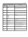
6.3.8 Min/Max memory - MIN MAX/M20
The process display unit can save a minimum and a maximum measured value. The input signal
or the signal processed using the linearization table are available as the signal source. The
memory is reset manually or using the digital input (see Section 6.3.4).
Function
(menu
item)
Ref. min/max
52
Parameter setting
Input
Lintab
Description
Signal source for the min/max value memory.
• Input = input signal
• Lintab = linearized input signal or current flow value
for channel calculation
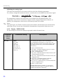
Commissioning
Function
(menu
item)
Parameter setting
Description
Dec. point
XXXXX
XXXX.X
XXX.XX
XX.XXX
X.XXXX
Number of digits after the decimal point for the
min/max value memory.
Min. value
0..99999
Displays the current minimum value in the memory.
Max. value
0..99999
Displays the current maximum value in the memory.
Reset min
No
Yes
Resets the minimum value memory.
Reset max
No
Yes
Resets the maximum value memory.
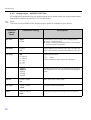
6.3.9 Linearization table - LIN. TABLE/M21
To linearize input variables, a linearization table can be saved in the measuring instrument, e.g.
to correct the level signal of a container for volume display.
Function
(menu
item)
Parameter setting
Description
Counts
2..32
2
Number of support points needed. At least two points
have to be entered.
Dimension
XXXXXXXXX
Select the dimension from the list or dimension as free
text (max. 9 characters long).
Dec. Y value
XXXXX
XXXX.X
XXX.XX
XX.XXX
X.XXXX
Decimal point position for the Y-values in the
linearization table.
Del. points
No
Yes
Delete all programmed support points.
53
Commissioning
Function
(menu
item)
Show points
Parameter setting
No
Yes
Description
Show all programmed support cells.
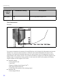
Tank linearization
Example:
G09-RIA452ZZ-15-00-xx-xx-011
Fig. 22: Example for tank linearization
You want to determine the amount of cereal filled into a silo, display this information on site and
transfer it to a process control system. A 4-20 mA level sensor determines the level in the
container, the connection between the level (m) and volume (m3) is known and the level is
proportional to the sensor current. The volume calculated is output as a 0-20 mA signal at the
analog output in proportion to the volume. In the event of a fault in the system, the analog
output outputs an error signal of 21.0 mA.
• Container empty:
– Sensor signal 4 mA
– Level 0 m
– Numeric display should show 0 (m3)
– Bar graph should show 0%
– 0 mA should be present at the analog output
• Container full:
– Sensor signal 20 mA
54
Commissioning
–
–
–
–
Level 10 m
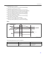
Numeric display should show 1500 (m3)
Bar graph should show 100%
20 mA should be present at the analog output
Point
1
2
3
4
5
6
7
8
9
10
Sensor
signal
(mA)
X
value
4,0
X
value
4.32
X
value
4.64
X
value
4.96
X
value
5.28
X
value
5.6
X
value
5.92
X
value
6.24
X
value
6.56
X
value
20.0
Display
value
(m3)
Y
value
0
Y
value
20
Y
value
50
Y
value
85
Y
value
115
Y
value
160
Y
value
210
Y
value
280
Y
value
400
Y
value
1500
The following parameters must be configured for the example above:
!
Menu
Function (menu item)
Setting value
LIN. TABLE / M 21
Counts
Dimension
Show points
Number of support points (10)
Dimension of lin. value (m3)
Display support points (Yes)
LINPOINTS 1 to 10 / M23 to 32
Each point
Each X value
Each Y value
Use point (Used)
X-value (as in table above)
Y-value (as in table above)
ANALOG OUT / M 3
Ref. num
Out range
Fail mode
Fail value
Output value (lin tab)
Signal type (0-20 mA)
Failsafe mode (const)
Value in event of error (21 mA)
DISPLAY / M 2
Ref. num.
Ref. bargraf
Reading on display (lin. table)
Signal source for bar graph (lin tab)
Note!
ReadWin® 2000 operating software supports the generation of a tank linearization table.
Here you can find a tank linearization generator which you can use to generate the linearization
table for standard and customer-specific tanks.
55
Commissioning
6.3.10 Support points of linearization table - LINPOINTS 1..X/M23..MXX
Displays the set value pairs of the linearization table. This menu item is only visible if a
linearization table was configured under Section 6.3.9 and "Yes" was selected in the "Show
points" parameter in the "LIN. TABLE/M21" menu.
Function
(menu
item)
Parameter setting
Description
Point
Used
Discard
Use or discard support point.
X value
-99999..99999
X-value of the linearization table. Corresponds to the
input value.
Y value
-99999..99999
Y-value that belongs to the previous X-value.
Corresponds to the converted measured value.
6.3.11 Operating parameter - PARAMETER/M55
In this menu item, configuration options such as the user code, failsafe mode of RIA452 to
NAMUR etc. can be configured.
Function
(menu
item)
Parameter setting
Description
User code
9999
The option of editing the operating parameters is locked
after entering a 4-digit digital sequence (limit value
code).
This lock is indicated on the display with the "key"
symbol.
Limit Code
Off
On
If the limit value code function is activated, only the
configuration of the limit values is permitted. All other
operating parameters cannot be modified.
Activation of restricted operation is indicated on the
display with the "key" symbol.
The item is only displayed if a user code was assigned.
Prog. name
ILU10xA
Displays the name of the device software currently
installed.
56
Commissioning
Function
(menu
item)
Parameter setting
Description
Version
V X.XX.XX
Version of the device software currently installed.
Func. alt.
Time
Count
Setting for controlling pump rotation in alternating
pump control.
• Time = switching time of the relay
• Count = switching frequency of the relay
Lock time
99.9
Locking time of the relay, 0 to 99.9 s
Rel. Mode
Off
On
Switching behavior of the relays.
• Off = relays de-energize in the event of a limit value
violation
• On = relays energize in the event of a limit value
violation
Grad. Time
1..100
Time setting for gradient evaluation, 1 to 100 s
Namur
No
Yes
Sensor evaluation to NAMUR (e.g. cable open circuit).
Only for 4 to 20 mA current signal.
Range 1
3.6 (0.0 to 22.0)
Range 2
3.8 (0.0 to 22.0)
Range 3
20.5 (0.0 to 22.0)
Range 4
21.0 (0.0 to 22.0)
Error limits for the input signal.
In the "NAMUR=Yes" operating mode, ranges 1 to 4
are assigned the limits specified by Namur NE 43 and
cannot be changed.
In the "NAMUR=No" operating mode, the error limits
can be freely selected. Here, please note that the
following applies: Range 1 < Range 2 < Range 3 <
Range 4.
Violation of these limits can be evaluated with a relay
for example ("Alarm" and "Alarm inverse" operating
mode).
Contrast
1 to 30
Setting for the display contrast.
• 1 = low contrast
• 30 = high contrast
57
Maintenance
7
Maintenance
No special maintenance work is required on the device.
8
58
Accessories
Name
Order No.
ReadWin® 2000 PC configuration software and serial cable with jack connector
3.5 mm for RS232 port.
RIA452A-VK
ReadWin® 2000 PC configuration software and serial cable for USB port with CDI
connecter.
TXU10A-xx
IP65 Field housing.
51009957
Troubleshooting
9
Troubleshooting
The following section provides you with an overview of possible causes of errors to provide you
with an initial troubleshooting aid.
9.1
#
Troubleshooting instructions
Warning!
In the case of Ex devices, fault diagnosis cannot be carried out on the open device as this annuls
the explosion protection.
Display
Cause
Remedy
No power supply connected
Check the power supply of the device.
No measured value display
The red marking for
overrange/underrange is flashing on the
bar graph.
!
The device must be replaced.
Analog output is > 10% above or below
the scaled range.
Check the scaling of the analog output
(Out 100% or Out 0%).
Note!
Errors for which an error code is shown on the display are described in Section 9.2.
Further information on the display is also provided in Section 5.2.1.
9.2
!
Power supply applied, device defective
Process error messages
Note!
Faults have the highest priority. The associated error code is displayed. A fault is present if the
memory module for writing and reading data is defective or if data could not be read correctly.
9.2.1 Device malfunction
Error code
Cause
Effect
Remedy
E 101
Bus error reading the
config/calibration data after
power-up
Faulty device functioning
Instrument error, notify
Service
E 102
Implausible operating data
(checksum)
Configuration lost
Perform preset
E 103
Implausible calibration data
Faulty device functioning
Instrument error, notify
Service
E 104
Bus error reading the
min/max data after
power-up
Incorrect min/max values
Reset min/max values
59
Troubleshooting
!
Error code
Cause
Effect
Remedy
E 105
Bus error reading the relay
data after power-up
Incorrect relay data
Reset relay data
E 106
Universal card bus error
Faulty universal input
functioning
Replace universal card, notify
Service
E 210
Pulse output, pulse buffer
overflow
A maximum of 10 pulses are
buffered
Set the parameters of the
pulse output in such a way
that the maximum frequency
is not exceeded
E 221
Pump error, digital input 1
E 222
Pump error, digital input 2
E 223
Pump error, digital input 3
E 224
Pump error, digital input 4
E 290
Number overshoot due to
decimal point shift
Relay goes to failsafe mode
Acknowledge error via
operation or switching power
on/off
Decimal point position
cannot be altered
Check decimal point position
and number range
Note!
The errors specified above can be evaluated with a relay in the operating mode "Alarm" and
"Alarm inverse".
9.2.2 Incorrect entries
Error code
Description
Reaction at device
E 290
The number of digits after the decimal point
cannot be increased due to number overflow of
the dependent parameters.
Error code is shown on the display until a key is
pressed.
60
Troubleshooting
9.3
Spare parts
G09-RIA452ZZ-09-00-xx-xx-000
Fig. 23: RIA452 spare parts
Item No.
Name
Order No.
1
Housing front
RIA452X-HA
2
Housing seal
50070730
3
Ex-cover (rear panel)
51008272
4
Rotary button with seal
RIA452X-HB
5
Relay board
RIA452X-RA
6
Mainboard 90 to 250 V, 50/60 Hz
RIA452X-MA
7
Mainboard 20 to 36 V DC; 20 to 28 V AC, 50/60 Hz
RIA452X-MB
Standard input card
RIA452X-IA
Standard input card ATEX, FM, CSA approval
RIA452X-IB
Multifunction input card
RIA452X-IC
8
Complete display board
RIA452X-DA
9
LC display (glass with background illumination)
RIA452X-DB
10
Terminal (power supply) 3-pin
50078843
61
Troubleshooting
Item No.
Name
Order No.
11
Terminal (relay 1-8) 6-pin
51005104
12
Terminal (analog input) 4-pin
51009302
13
Terminal (analog output, Open Collector, transmitter power supply) 6-pin
51008588
14
Terminal (digital inputs) 5-pin
51008587
15
Jumper operating lock
50033350
No Item No.
Casing fixing clip RIA452 (1 piece)
50084623
9.4
Return
For a return, e.g. in case of repair, the device must be sent in protective packaging. The original
packaging offers the best protection. Repairs must only be carried out by your supplier's service
organization.
!
Note!
Please enclose a note describing the fault and the application when sending the unit in for repair.
9.5
Disposal
The device contains electronic components and must, therefore, be disposed of as electronic
waste in the event of disposal. Please observe in particular the local waste disposal regulations
of your country.
62
Technical data
10
Technical data
10.1 Input
10.1.1 Measured variable
Current (standard)
Digital inputs (standard)
Current/voltage, resistance, resistance thermometer, thermocouples (universal input option)
10.1.2 Measuring ranges
Current input:
• 0/4 to 20 mA +10% overrange, 0 to 5 mA
• Short-circuit current: max. 150 mA
• Input impedance: ≤ 5 Ω
• Reaction time: ≤ 100 ms
Universal input:
Current:
• 0/4 to 20 mA +10% overrange, 0 to 5 mA
• Short-circuit current: max. 100 mA
• Input impedance: ≤ 50 Ω
Voltage:
• ±150 mV, ±1 V, ±10 V, ±30 V, 0 to 100 mV, 0 to 200 mV, 0 to 1 V, 0 to 10 V
• Input impedance: ≥ 100 kΩ
Resistance:
• 30 to 3,000 Ω in 3/4 wire technology
Resistance thermometer:
• Pt100/500/1000, Cu50/100, Pt50 in 3/4-wire technology
• Measuring current for Pt100/500/1000 = 250 μA
Thermocouple types:
• J, K, T, N, B, S, R as per IEC584
• D, C as per ASTME998
• U, L as per DIN43710/GOST
• Reaction time: ≤ 100 ms
Digital input:
• Voltage level -3 to 5 V low, 12 to 30 V high (as per DIN19240)
• Input voltage max. 34.5 V
• Input current typ. 3 mA with overload and reverse polarity protection
• Sampling frequency max. 10 Hz
10.1.3 Galvanic isolation
Towards all other circuits
63
Technical data
10.1.4 Performance characteristics
Reference operating conditions
Power supply: 230 V AC ±10%, 50 Hz ±0.5 Hz
Warm-up period: 90 min
Ambient temperature: 25 °C (77 °F)
Maximum measured error
Current input:
Accuracy
0.1% of full scale
Resolution
13 bit
Temperature drift
≤ 0.4%/10 K (≤ 0.4%/18 °F)
Universal input:
Accuracy
Input:
Range:
Maximum measured error of measuring
range (oMR):
Current
0 to 20 mA, 0 to 5 mA, 4 to 20 mA;
overrange: to 22 mA
± 0.10%
Voltage > 1 V
0 to 10 V, ± 10 V, ± 30 V
± 0.10%
Voltage ≤ 1 V
± 1 V, 0 to 1 V, 0 to 200 mV, 0 to
100 mV, ± 150 mV
± 0.10%
Resistance
thermometer
Pt100, -200 to 600 °C (-328 to 1112 °F)
(IEC751, JIS1604, GOST)
Pt500, -200 to 600 °C (-328 to 1112 °F)
(IEC751, JIS1604)
Pt1000, -200 to 600 °C (-328 to 1112
°F) (IEC751, JIS1604)
4-wire: ± (0.10% oMR + 0.3 K (0.54 °F))
3-wire: ± (0.15% oMR + 0.8 K (1.44 °F))
Cu100, -200 to 200 °C (-328 to 392 °F)
(GOST)
Cu50, -200 to 200 °C (-328 to 392 °F)
(GOST)
Pt50, -200 to 600 °C (-328 to 1112 °F)
(GOST)
4-wire: ± (0.20% oMR + 0.3 K (0.54 °F))
3-wire: ± (0.20% oMR + 0.8 K (1.44 °F))
30 to 3000 Ω
4-wire: ± (0.20% oMR + 0.3 K (0.54 °F))
3-wire: ± (0.20% oMR + 0.8 K (1.44 °F))
Resistance
measurement
64
Technical data
Accuracy
Thermocouples
Type J (Fe-CuNi), -210 to 999.9 °C
(-346 to 1382 °F) (IEC584)
± (0.15% oMR +0.5 K (0.9 °F))
from -100 °C (-148 °F)
Type K (NiCr-Ni), -200 to 1372 °C
(-328 to 2502 °F) (IEC584)
± (0.15% oMR +0.5 K (0.9 °F))
from -130 °C (-234 °F)
Type T (Cu-CuNi), -270 to 400 °C
(-454 to 752 °F) (IEC584)
± (0.15% oMR +0.5 K (0.9 °F))
from -200 °C (-328 °F)
Type N (NiCrSi-NiSi), -270 to 1300 °C
(-454 to 2372 °F) (IEC584)
± (0.15% oMR +0.5 K (0.9 °F))
from -100 °C (-148 °F)
Type B (Pt30Rh-Pt6Rh), 0 to 1820 °C
(32 to 3308 °F) (IEC584)
± (0.15% oMR +1.5 K (2.7 °F))
from 600 °C (1112 °F)
Type D (W3Re/W25Re), 0 to 2315 °C
(32 to 4199 °F) (ASTME998)
± (0.15% oMR +1.5 K (2.7 °F))
from 500 °C (932 °F)
Type C (W5Re/W26Re), 0 to 2315 °C
(32 to 4199 °F) (ASTME998)
± (0.15% oMR +1.5 K (2.7 °F))
from 500 °C (from 932 °F)
Type L (Fe-CuNi), -200 to 900 °C
(-328 to 1652 °F) (DIN43710, GOST)
± (0.15% oMR +0.5 K (0.9 °F))
from -100 °C (-148 °F)
Type U (Cu-CuNi), -200 to 600 °C
(-328 to 1112 °F) (DIN 43710)
± (0.15% oMR +0.5 K (0.9 °F))
from -100 °C (-148 °F)
Type S (Pt10Rh-Pt), 0 to 1768 °C
(32 to 3214 °F) (IEC584)
± (0.15% oMR +3.5 K (6.3 °F))
for 0 to 100 °C (32 to 212 °F)
± (0.15% oMR +1.5 K (2.7 °F))
for 100 to 1768 °C (232 to 3214 °F)
Type R (Pt13Rh-Pt), -50 to 1768 °C
(-58 to 4199 °F) (IEC584)
± (0.15% oMR +3.5 K (6.3 °F))
for 0 to 100 °C (32 to 212 °F)
± (0.15% oMR +1.5 K (2.7 °F))
for 100 to 1768 °C (232 to 3214 °F)
Resolution
16 bit
Temperature drift
Temperature drift: ≤ 0.1%/10 K (0.1%/18 °F)
Current output:
Linearity
0.1% of full scale
Resolution
13 bit
Temperature drift
≤ 0.1%/10K (0.1%/18 °F)
Output ripple
10 mV at 500 Ω for frequencies ≤ 50 kHz
65
Technical data
Voltage output
Linearity
0.1% of full scale
Resolution
13 bit
Temperature drift
≤ 0.1%/10K (0.1%/18 °F)
10.1.5 Power supply
Electrical connection
G09-RIA452ZZ-04-01-xx-en-000
Fig. 24: Terminal assignment of process display unit
66
Technical data
Universal input option
The device can be optionally equipped with a universal input instead of a current input.
G09-RIA452xx-04-10-xx-en-002
Fig. 25: Universal input terminal assignment
Supply voltage
Low voltage power unit 90 to 250 V AC 50/60 Hz
Extra-low voltage power unit: 20 to 36 V DC or 20 to 28 V AC 50/60 Hz
Power consumption
Max. 24 VA
Connection data interface
RS232
• Connection: jack socket 3.5 mm, rear of device
• Transmission protocol: ReadWin® 2000
• Transmission rate: 38,400 Baud
67
Technical data
10.2 Output
10.2.1 Output signal
Relay, transmitter power supply (standard)
Current, voltage, pulse, intrinsically safe transmitter power supply (option)
10.2.2 Signal on alarm
No measured value visible on the LC display, no background illumination, no sensor power
supply, no output signals, relays behave in safety-oriented manner.
10.2.3 Current/voltage output
Span:
• 0/4 to 20 mA (active), 0 to 10 V (active)
Load:
• ≤ 600 Ω (current output)
• Max. loop current 22 mA (voltage output)
Signal characterization:
• Signal freely scalable
Galvanic isolation towards all other circuits
10.2.4 Pulse output
•
•
•
•
•
Frequency range to 12.5 kHz
Imax = 200 mA
Umax = 28 V
Ulow/max = 2 V at 200 mA
Pulse width = 0.04 to 2000 ms
10.2.5 Relay
Signal characterization:
• Binary, switches when the limit value is reached
Switch function: limit relay switches for the operating modes:
• Minimum/maximum safety
• Alternating pump control function
• Batch function
• Time control
• Window function
• Gradient
• Device malfunction
• Sensor malfunction
Switching threshold:
• Freely programmable
68
Technical data
Hysteresis:
• 0 to 99%
Signal source:s
• Analog input signal
• Integrated value
• Digital input
Number:
• 4 in basic unit (can be extended to 8 relays, option)
Electrical specifications:
• Relay type: changeover
• Relay switching capacity: 250 V AC / 30 V DC, 3 A
• Switch cycles: typically 105
• Switching frequency: max. 5 Hz
• Minimum switching load: 10 mA / 5 V DC
Galvanic isolation towards all other circuits
!
Note! Assignment:
Mixed assignment of low and extra-low voltage circuits is not permitted for neighboring relays.
10.2.6 Transmitter power supply
Transmitter power supply 1, terminal 81/82 (optionally intrinsically safe):
Electrical specifications:
• Output voltage: 24 V ± 15%
• Output current: max. 22 mA (at Uout ≥ 16 V, sustained short-circuit proof)
• Impedance: ≤ 345 Ω
Approvals:
• ATEX
• FM
• CSA
Transmitter power supply 2, terminal 91/92:
Electrical specifications:
• Output voltage: 24 V ± 15%
• Output current: max. 250 mA (sustained short-circuit proof)
10.3 Installation
10.3.1 Installation instructions
Mounting location
Panel, cutout 92 x 92 mm (3.62x3.62 inch) (see 'Mechanical construction').
Orientation
Horizontal +/- 45° in every direction
69
Technical data
10.3.2 Environment
Ambient temperature range
-20 to +60 °C (-4 to 140 °F))
Storage temperature
-30 to +70 °C (-22 to 158 °F)
Operating height
< 3000 m above MSL (9800 ft)
Climate class
As per IEC 60654-1, Class B2
Condensation
Front: permitted
Device casing: not permitted
Degree of protection
Front IP 65 / NEMA 4
Device casing IP 20
Shock and vibration resistance
2(+3/-0) Hz - 13.2 Hz: ±1.0 mm
13.2 Hz - 100 Hz: 0.7 g
Electromagnetic compatibility (EMC)
• Interference immunity:
To IEC 61326 industrial environments / NAMUR NE 21
• Interference emissions:
To IEC 61326 Class A
70
Technical data
10.4 Mechanical construction
10.4.1 Design, dimensions
G09-RIA452ZZ-06-01-xx-xx-000
Fig. 26: Dimensions of the process display unit
G09-RIA452xx-06-01-00-en-001
Fig. 27: Panel cutout
G09-RIA452xx-06-00-xx-xx-002
Fig. 28: Dimensions of the field housing
71
Technical data
10.4.2 Weight
Approx. 500 g (17.64 oz)
10.4.3 Material
• Housing front: ABS plastic, galvanized
• Housing casing: plastic PC10GF
10.4.4 Terminals
Pluggable screw terminals, core size 1.5 mm2 (16 AWG) solid, 1.0 mm2 (18 AWG) strand with
wire ferrule
10.5 Human interface
10.5.1 Display elements
G09-RIA452ZZ-07-01-00-xx-000
Fig. 29: LC display of process display unit
Item 1: Device status LEDs: green - device ready for operation; red - device or sensor malfunction
Item 2: Bar graph with overrange and underrange
Item 3: 7-digit 14-segment display
Item 4: Unit and text field 9x77 dot matrix
Item 5: Relay status display: if power is supplied to a relay, the symbol is displayed
Item 6: Status display, digital inputs
Item 7: Symbol for 'device operation blocked'
• Display range
-99999 to +99999 for measured values
0 to 9999999 for counter values
• Signaling
– Relay activation
72
Technical data
– Measuring range overshoot/undershoot
10.5.2 Operating elements
Jog/shuttle dial
10.5.3 Remote operation
Configuration
The device can be configured with the PC software ReadWin® 2000.
Interface
CDI interface at device; connection to PC via USB box (see 'Accessories')
RS232 interface at device; connection with serial interface cable (see 'Accessories')
10.6 Certificates and approvals
10.6.1 CE mark
The device meets the legal requirements of the EU directives. Endress+Hauser confirms that the
device has been tested successfully by affixing the CE mark.
10.6.2 Ex approval
Information about currently available Ex versions (ATEX, FM, CSA, etc.) can be supplied by your
E+H Sales Center on request. All explosion protection data are given in a separate
documentation which is available upon request.
10.6.3 Other standards and guidelines
• IEC 60529:
Degrees of protection by housing (IP code)
• IEC 61010-1:
Protection measures for electrical equipment for measurement, control, regulation and
laboratory procedures
• CSA 1010.1
Safety requirements for electrical equipment for measurement, control, and laboratory use General requirements
• FM 3610
Intrinsically safe apparatus and associated apparatus for use in class 1, 2 and 3, division 1
hazardous (classified) locations
• CSA C22.2.157
Intrinsically safe & non-incendive equipment for use in hazardous locations
• CSA E79-11
Electrical apparatus for explosive gas atmospheres - intrinsic safety "i"
• EN 50020
Electrical apparatus for hazardous areas - intrinsic safety "I"
73
Technical data
10.7 Documentation
System components - display unit, top-hat rail devices, overvoltage protection and energy
computer (FA016K)
Supplementary Ex documentation:
ATEX II(1)GD: XA 053R
74
Appendix
11
Appendix
11.1 Flow conversion
Conversion of various units to m3/h
Liter
• 1 l/s = 3.6 m3/h
• 1 l/min = 0.06 m3/h
• 1 l/s = 0.001 m3/h
US megagallon
• 1 USMgal/s = 13,627,481.6155 m3/h
• 1 USMgal/min = 227,124.6936 m3/h
• 1 USMgal/h = 3785.4118 m3/h
Hectoliter
• 1 hl/s = 360 m3/h
• 1 hl/min = 6 m3/h
• 1 hl/h = 0.1 m3/h
US Barrel
• 1 US bl/s = 429.264 m3/h
• 1 US bl/min = 7.1544 m3/h
• 1 US bl/h = 0.1192 m3/h
Cubic meter
• 1 m3/s = 3600 m3/h
• 1 m3/min = 60 m3/h
Imperial gallon
• 1 Imp. gal/s = 16.3659 m3/h
• 1 Imp gal/min = 0.2728 m3/h
• 1 Imp gal/h = 0.004546 m3/h
Megaliter
• 1 Ml/s = 3,600,000 m3/h
• 1 Ml/min = 6,000 m3/h
• 1 Ml/h = 1000 m3/h
US gallon
• 1 USgal/s = 13.6274 m3/h
• 1 USgal/min = 0.2271 m3/h
• 1 USgal/h = 0.003785 m3/h
US kilogallon
• 1 US Kgal/s = 13627.4444 m3/h
• 1 US Kgal/min = 227.1241 m3/h
• 1 US Kgal/h = 3.7854 m3/h
Imperial barrel
• 1 Imp. bl/s = 589.1955 m3/h
• 1 Imp. bl/min = 9.8195 m3/h
• 1 Imp. gal/h = 0.1637 m3/h
Cubic inch
• 1 in3/s = 0.05899 m3/h
• 1 in3/min = 0.00098322 m3/h
• 1 in3/h = 0.000016387 m3/h
Cubic foot
• 1 ft3/s = 101.9406 m3/h
• 1 ft3/min = 1.699 m3/h
• 1 ft3/h = 0.0283 m3/h
75
Index
Numerics
Curve (function) . . . . . . . . . . . . . . . . . . . . . . . . 27
0% value (function). . . . . . . . . . . . . . . . . . . . . . . 27
100% value (function). . . . . . . . . . . . . . . . . . . . . 27
24-hour activation function. . . . . . . . . . . . . . . . . 43
D
A
Adjusting the analog input. . . . . . . . . . . . . . . . . .
Alpha (function) . . . . . . . . . . . . . . . . . . . . . . . . .
Alternate . . . . . . . . . . . . . . . . . . . . . . . . . . . . . .
Alternate (function). . . . . . . . . . . . . . . . . . . . . . .
Alternating pump control . . . . . . . . . . . . . . . . . .
Analog input
Adjusting . . . . . . . . . . . . . . . . . . . . . . . . . . . .
Parameter. . . . . . . . . . . . . . . . . . . . . . . . . . . .
Analog output
Parameter. . . . . . . . . . . . . . . . . . . . . . . . . . . .
28
46
42
36
42
28
25
30
B
Bar 0% (function) . . . . . . . . . . . . . . . . . . . . . . . .
Bar 100% (function) . . . . . . . . . . . . . . . . . . . . . .
Bar rise (function) . . . . . . . . . . . . . . . . . . . . . . . .
Beta (function) . . . . . . . . . . . . . . . . . . . . . . . . . .
BST Venturi (function) . . . . . . . . . . . . . . . . . . . .
BST V-weir (function) . . . . . . . . . . . . . . . . . . . . .
29
29
29
46
48
49
C
C (function) . . . . . . . . . . . . . . . . . . . . . . . . . . . .
Calc. flow (function) . . . . . . . . . . . . . . . . . . . . . .
Certificates and approvals . . . . . . . . . . . . . . . . . .
Code
User . . . . . . . . . . . . . . . . . . . . . . . . . . . . . . . .
Comp. Temp (function). . . . . . . . . . . . . . . . . . . .
Configuration
Operating parameter . . . . . . . . . . . . . . . . . . . .
Connecting external sensors . . . . . . . . . . . . . . . .
Current input . . . . . . . . . . . . . . . . . . . . . . . . .
Universal input . . . . . . . . . . . . . . . . . . . . . . . .
Connecting the power supply . . . . . . . . . . . . . . .
Connection (function). . . . . . . . . . . . . . . . . . . . .
Const. temp (function) . . . . . . . . . . . . . . . . . . . .
Contrast (function) . . . . . . . . . . . . . . . . . . . . . . .
Count (function) . . . . . . . . . . . . . . . . . . . . . . . . .
Counts (function) . . . . . . . . . . . . . . . . . . . . . . . .
Current input
Connecting external sensors . . . . . . . . . . . . . .
76
46
45
73
24
27
56
15
15
15
14
26
27
57
37
53
15
Damp (function) . . . . . . . . . . . . . . . . . . . . . . . . 27
Dec. factor (function). . . . . . . . . . . . . . . . . . . . . 44
Dec. flow (function). . . . . . . . . . . . . . . . . . . . . . 45
Dec. point (function) . . . . . . . 27, 29–30, 36, 46, 53
Dec. value (function) . . . . . . . . . . . . . . . . . . . . . 52
Dec. Y value (function) . . . . . . . . . . . . . . . . . . . 53
Dec.point T (function) . . . . . . . . . . . . . . . . . . . . 44
Del. points (function). . . . . . . . . . . . . . . . . . . . . 53
Delay . . . . . . . . . . . . . . . . . . . . . . . . . . . . . . . . 41
Delay (function). . . . . . . . . . . . . . . . . . . . . . . . . 36
Device malfunction . . . . . . . . . . . . . . . . . . . . . . 59
Digital input
Parameter . . . . . . . . . . . . . . . . . . . . . . . . . . . 32
Dim. flow (function) . . . . . . . . . . . . . . . . . . . . . 46
Dim. input (function). . . . . . . . . . . . . . . . . . . . . 45
Dimension (function). . . . . . . . . . . . . . . 27, 44, 53
Dimensions . . . . . . . . . . . . . . . . . . . . . . . . . . . . . 8
Disabling
Configuration . . . . . . . . . . . . . . . . . . . . . . . . 24
Disabling the programming mode. . . . . . . . . . . . 24
Display . . . . . . . . . . . . . . . . . . . . . . . . . . . . . . . 21
Parameter . . . . . . . . . . . . . . . . . . . . . . . . . . . 28
Display sw. (function) . . . . . . . . . . . . . . . . . . . . 29
Documentation . . . . . . . . . . . . . . . . . . . . . . . . . 74
E
Electrical connection
Post-connection check (checklist) . . . . . . . . . 16
Entering text . . . . . . . . . . . . . . . . . . . . . . . . . . . 23
Error codes . . . . . . . . . . . . . . . . . . . . . . . . . . 59–60
F
Factor (function) . . . . . . . . . . . . . . . . . . . . . . . . 44
Fail mode (function) . . . . . . . . . . . . . . . . . . . . . 31
Fail value (function). . . . . . . . . . . . . . . . . . . . . . 31
Flow measurement
Formula for calculation . . . . . . . . . . . . . . . . . 51
Scaling constant. . . . . . . . . . . . . . . . . . . . . . . 51
Flumes Weir (function) . . . . . . . . . . . . . . . . . . . 47
Func. alt. (function) . . . . . . . . . . . . . . . . . . . . . . 57
Function . . . . . . . . . . . . . . . . . . . . . . . . . . . 32, 36
G
Gamma (function) . . . . . . . . . . . . . . . . . . . . . . . 46
Grad. Time (function) . . . . . . . . . . . . . . . . . . . . . 57
Min/max memory
Parameter . . . . . . . . . . . . . . . . . . . . . . . . . . . . 52
Mounting location. . . . . . . . . . . . . . . . . . . . . . . . . 8
H
N
Hardware locking . . . . . . . . . . . . . . . . . . . . . . . . 24
Human interface. . . . . . . . . . . . . . . . . . . . . . . . . 72
Hysteresis (function) . . . . . . . . . . . . . . . . . . . . . . 36
I
Incorrect entries . . . . . . . . . . . . . . . . . . . . . . . . .
Input . . . . . . . . . . . . . . . . . . . . . . . . . . . . . . . . .
Installation . . . . . . . . . . . . . . . . . . . . . . . . . . . . .
Integr. base (function). . . . . . . . . . . . . . . . . . . . .
Integration
Parameter . . . . . . . . . . . . . . . . . . . . . . . . . . .
Integration (function) . . . . . . . . . . . . . . . . . . . . .
Integration function . . . . . . . . . . . . . . . . . . . . . .
ISO Venturi (function) . . . . . . . . . . . . . . . . . . . .
60
63
69
44
44
44
50
47
K
Kha-Venturi (function) . . . . . . . . . . . . . . . . . . . . 47
L
Level (function) . . . . . . . . . . . . . . . . . . . . . . . . .
Limit code (function) . . . . . . . . . . . . . . . . . . . . .
Limit values
Parameter . . . . . . . . . . . . . . . . . . . . . . . . . . .
Linearization function. . . . . . . . . . . . . . . . . . . . .
Linearization table
Parameter . . . . . . . . . . . . . . . . . . . . . . . . . . .
Lock time (function) . . . . . . . . . . . . . . . . . . . . . .
32
56
35
54
53
57
M
Max. value (function) . . . . . . . . . . . . . . . . . . . . .
Mechanical construction. . . . . . . . . . . . . . . . . . .
Menu
Analog Out. . . . . . . . . . . . . . . . . . . . . . . . . . .
Digital Inp. . . . . . . . . . . . . . . . . . . . . . . . . . . .
Display. . . . . . . . . . . . . . . . . . . . . . . . . . . . . .
Input . . . . . . . . . . . . . . . . . . . . . . . . . . . . . . .
Limit . . . . . . . . . . . . . . . . . . . . . . . . . . . . . . .
LIN. Table . . . . . . . . . . . . . . . . . . . . . . . . . . .
LINPOINTS 1..X . . . . . . . . . . . . . . . . . . . . . .
MIN MAX . . . . . . . . . . . . . . . . . . . . . . . . . . .
PARAMETER . . . . . . . . . . . . . . . . . . . . . . . . .
Pulse out . . . . . . . . . . . . . . . . . . . . . . . . . . . .
Min. value (function) . . . . . . . . . . . . . . . . . . . . .
53
71
30
32
28
25
35
53
56
52
56
51
53
Nameplate . . . . . . . . . . . . . . . . . . . . . . . . . . . . . . 6
Namur (function) . . . . . . . . . . . . . . . . . . . . . . . . 57
NFX V-weir (function). . . . . . . . . . . . . . . . . . . . . 50
NFXRect.WThr (function) . . . . . . . . . . . . . . . . . . 49
NFXRect.WTO (function) . . . . . . . . . . . . . . . . . . 49
O
Offset (function) . . . . . . . . . . . . . . . . . . . . . . 27, 30
Open circ. (function) . . . . . . . . . . . . . . . . . . . . . . 27
Operating matrix. . . . . . . . . . . . . . . . . . . . . . . . . 17
Operating mode
Alarm . . . . . . . . . . . . . . . . . . . . . . . . . . . . . . . 40
Grad . . . . . . . . . . . . . . . . . . . . . . . . . . . . . . . . 40
Max . . . . . . . . . . . . . . . . . . . . . . . . . . . . . . . . 39
Min . . . . . . . . . . . . . . . . . . . . . . . . . . . . . . . . 38
Operating parameter
Configuration . . . . . . . . . . . . . . . . . . . . . . . . . 56
Orientation . . . . . . . . . . . . . . . . . . . . . . . . . . . . . . 8
Out 0% (function) . . . . . . . . . . . . . . . . . . . . . . . . 30
Out 100% (function) . . . . . . . . . . . . . . . . . . . . . . 30
Out damp (function) . . . . . . . . . . . . . . . . . . . . . . 30
Out range (function) . . . . . . . . . . . . . . . . . . . . . . 30
Output . . . . . . . . . . . . . . . . . . . . . . . . . . . . . . . . 68
P
Palmer-Bow. (function) . . . . . . . . . . . . . . . . . . . . 48
Parameter
Analog input . . . . . . . . . . . . . . . . . . . . . . . . . . 25
Analog output . . . . . . . . . . . . . . . . . . . . . . . . . 30
Digital input . . . . . . . . . . . . . . . . . . . . . . . . . . 32
Display . . . . . . . . . . . . . . . . . . . . . . . . . . . . . . 28
Integration . . . . . . . . . . . . . . . . . . . . . . . . . . . 44
Limit values . . . . . . . . . . . . . . . . . . . . . . . . . . 35
Linearization table. . . . . . . . . . . . . . . . . . . . . . 53
Min/max memory . . . . . . . . . . . . . . . . . . . . . 52
Pulse output . . . . . . . . . . . . . . . . . . . . . . . . . . 51
Support points. . . . . . . . . . . . . . . . . . . . . . . . . 56
Parshall (function) . . . . . . . . . . . . . . . . . . . . . . . . 48
Performance characteristics . . . . . . . . . . . . . . . . . 64
Point (function) . . . . . . . . . . . . . . . . . . . . . . . . . . 56
Power supply . . . . . . . . . . . . . . . . . . . . . . . . 14, 66
Pre-counter (function) . . . . . . . . . . . . . . . . . . . . . 44
Preset counter . . . . . . . . . . . . . . . . . . . . . . . . . . . 50
Prog. name (function) . . . . . . . . . . . . . . . . . . . . .
Pulse output
Parameter. . . . . . . . . . . . . . . . . . . . . . . . . . . .
Pulse width (function). . . . . . . . . . . . . . . . . . . . .
Pump monitoring function . . . . . . . . . . . . . . . . .
56
51
52
33
R
Range 1 (function) . . . . . . . . . . . . . . . . . . . . . . . 57
Range 2 (function) . . . . . . . . . . . . . . . . . . . . . . . 57
Range 3 (function) . . . . . . . . . . . . . . . . . . . . . . . 57
Range 4 (function) . . . . . . . . . . . . . . . . . . . . . . . 57
Rect.WThr (function) . . . . . . . . . . . . . . . . . . . . . 49
Rect.WTO (function) . . . . . . . . . . . . . . . . . . . . . 48
Ref. bargraf (function) . . . . . . . . . . . . . . . . . . . . . 29
Ref. integr. (function) . . . . . . . . . . . . . . . . . . . . . 44
Ref. Min/Max (function) . . . . . . . . . . . . . . . . . . 52
Ref. num. (function) . . . . . . . . . . . . . . . . 28, 30, 35
Rel. Mode (function). . . . . . . . . . . . . . . . . . . . . . 57
Repairs . . . . . . . . . . . . . . . . . . . . . . . . . . . . . . 4, 62
Reset (function) . . . . . . . . . . . . . . . . . . . . . . . . . 37
Reset max (function). . . . . . . . . . . . . . . . . . . . . . 53
Reset min (function) . . . . . . . . . . . . . . . . . . . . . . 53
Runtime (function) . . . . . . . . . . . . . . . . . . . . . . . 37
S
Sampl. time (function). . . . . . . . . . . . . . . . . . . . .
Scaling the analog input . . . . . . . . . . . . . . . . . . .
Sensors
Connecting external - . . . . . . . . . . . . . . . . . . .
Set count A (function). . . . . . . . . . . . . . . . . . . . .
Set count B (function) . . . . . . . . . . . . . . . . . . . . .
Setpoint A (function). . . . . . . . . . . . . . . . . . . . . .
Setpoint B (function) . . . . . . . . . . . . . . . . . . . . . .
Show points (function) . . . . . . . . . . . . . . . . . . . .
Signal type (function) . . . . . . . . . . . . . . . . . . . . .
Sim pulseout (function) . . . . . . . . . . . . . . . . . . . .
Simu mA (function) . . . . . . . . . . . . . . . . . . . . . .
Simu relay (function) . . . . . . . . . . . . . . . . . . . . .
Simu V (function) . . . . . . . . . . . . . . . . . . . . . . . .
Support points
Parameter. . . . . . . . . . . . . . . . . . . . . . . . . . . .
Sw. delay (function) . . . . . . . . . . . . . . . . . . . . . .
Sw. period (function) . . . . . . . . . . . . . . . . . . . . .
74
72
63
69
71
68
64
66
11
14
23
45
49
U
Unit value (function) . . . . . . . . . . . . . . . . . . . . .
Units
Conversion . . . . . . . . . . . . . . . . . . . . . . . . . .
Universal input . . . . . . . . . . . . . . . . . . . . . . . . .
Connecting external sensors . . . . . . . . . . . . .
Terminal assignment . . . . . . . . . . . . . . . . . . .
User code . . . . . . . . . . . . . . . . . . . . . . . . . . . . .
User code (function) . . . . . . . . . . . . . . . . . . . . .
52
75
13
15
14
24
56
V
32
28
Version (function) . . . . . . . . . . . . . . . . . . . . . . . 57
V-weir (function). . . . . . . . . . . . . . . . . . . . . . . . 49
15
45
45
36
36
54
26
52
31
37
31
W
56
37
37
T
Tank linearization . . . . . . . . . . . . . . . . . . . . . . . . 54
Technical data
Certificates and approvals . . . . . . . . . . . . . . . . 73
78
Documentation . . . . . . . . . . . . . . . . . . . . . . .
Human interface . . . . . . . . . . . . . . . . . . . . . .
Input. . . . . . . . . . . . . . . . . . . . . . . . . . . . . . .
Installation . . . . . . . . . . . . . . . . . . . . . . . . . .
Mechanical construction . . . . . . . . . . . . . . . .
Output . . . . . . . . . . . . . . . . . . . . . . . . . . . . .
Performance characteristics . . . . . . . . . . . . . .
Power supply. . . . . . . . . . . . . . . . . . . . . . . . .
Terminal assignment . . . . . . . . . . . . . . . . . . . . .
Universal input . . . . . . . . . . . . . . . . . . . . . . .
Text entry . . . . . . . . . . . . . . . . . . . . . . . . . . . . .
Totalizer (function) . . . . . . . . . . . . . . . . . . . . . .
Trap. W TO (function) . . . . . . . . . . . . . . . . . . . .
Width (function) . . . . . . . . . . . . . . . . . . . . . . . . 47
X
X value (function) . . . . . . . . . . . . . . . . . . . . . . . 56
Y
Y value (function) . . . . . . . . . . . . . . . . . . . . . . . 56
USA
Canada
México
Instruments International
Endress+Hauser, Inc.
2350 Endress Place
Greenwood, IN 46143
USA
Endress+Hauser Canada
1075 Sutton Drive
Burlington, ON L7L 5Z8
Canada
Tel. 317-535-7138
Fax 317-535-8498
Sales 888-ENDRESS
Service 800-642-8737
[email protected]
www.us.endress.com
Tel. 905-681-9292
800-668-3199
Fax 905-681-9444
www.ca.endress.com
Endress+Hauser México S.A. de C.V.
Fernando Montes de Oca 21 Edificio A Piso 3
Fracc. Industrial San Nicolás
54030 Tlalnepantla de Baz
Estado de México
México
Endress+Hauser
Instruments International AG
Kaegenstrasse 2
4153 Reinach
Switzerland
BA254R/24/ae/09.07
71064276
FM+SGML6.0 ProMoDo
Tel. +52 55 5321 2080
Fax +52 55 5321 2099
mailto: www.mx.endress.com
Tel. +41 61 715 81 00
Fax +41 61 715 25 00
www.endress.com
[email protected]