1
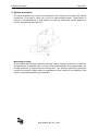
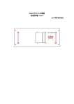
® Badger Meter Europa GmbH INSTALLATION AND OPERATION MANUAL April 2013 MID_M5000_BA_02_1304 Contents Page 1. Basic safety recommendations ........................................................................................ 1 2. System description............................................................................................................ 3 3. Installation .......................................................................................................................... 4 3.1 General information ................................................................................................... 4 3.1.1 Temperature ranges ..................................................................................... 4 3.1.2 Protection class ............................................................................................ 4 3.1.3 Transport ...................................................................................................... 5 3.2 Installation .................................................................................................................. 6 3.2.1 Meter orientation........................................................................................... 6 3.2.2 Inlet and outlet pipe ...................................................................................... 6 3.2.3 Meter location ............................................................................................... 7 3.2.4 Pipe reducer requirements ........................................................................... 8 3.2.5 Separate version .......................................................................................... 9 3.2.6 Grounding and potential equalization ........................................................... 9 3.2.7 Plastic or lined pipelines ............................................................................. 10 3.2.8 Pipelines with cathodic protection .............................................................. 10 3.2.9 Electrically disturbed environment .............................................................. 11 4. Electrical connections..................................................................................................... 12 4.1 Power ....................................................................................................................... 13 4.1.1 Battery ........................................................................................................ 13 4.1.2 Battery backup............................................................................................ 14 4.2 Separate version ...................................................................................................... 15 4.2.1 Connection on the amplifier ........................................................................ 15 4.2.2 Connection on the detector ........................................................................ 15 4.2.3 Signal cable specification ........................................................................... 17 4.3 Configuring input/output (I/O)................................................................................... 18 5. Parametering .................................................................................................................... 19 6. Main menu ........................................................................................................................ 21 7. Troubleshooting .............................................................................................................. 35 7.1 Replace meter´s electronics .................................................................................... 37 8. Technical data .................................................................................................................. 38 8.1 Detector type VI ....................................................................................................... 38 8.2 Amplifier type B-MAG™ I M5000 ............................................................................. 40 8.3 Error limits ................................................................................................................ 41 8.4 Size selection ........................................................................................................... 42 9. Programm structure ........................................................................................................ 43 10. Return of goods for repair ............................................................................................. 46 MID_M5000_BA_02_1304 Basic safety recommendations Page 1/46 1. Basic safety recommendations Before installing or using this product, please read this instruction manual thoroughly. Only qualified personnel should install and/or repair this product. If a fault appears, contact your distributor. The electromagnetic flow meter is only suitable for the measurement of conductive fluids. The manufacturer is not liable for damages that result from inproper use or from use that is not in accordance with the requirements. The meters are constructed according to state-of-the-art technology and tested operationally reliable. They have left the factory in a faultless condition concerning safety regulations. The mounting, electric installation, putting into operation and maintenance of the meter is to be carried out by suitable technicians. Furthermore the operating personnel has to be trained by the operating authority and the instructions of this manual have to be followed. Basically you have to respect the regulations for the opening and repairing of electrical equipment applicable in your country. Installation Do not place any unit on an unstable surface that may allow it to fall. Never place the units above a radiator or heating unit. Route all cabling away from potential hazards. Isolate from the mains before removing any covers. Power connection Use only the type of power source suitable for electronic equipment. If in doubt, contact your distributor. Ensure that any power cables are of a sufficiently high current rating. All units must be earthed to eliminate risk of electric shock. Failure to properly earth a unit may cause damage to that unit or data stored within it. Protection class The device has protection class IP 67/68. Setup & operation Adjust only those controls that are covered by the operating instructions. Improper adjustment of other controls may result in damage, incorrect operation or loss of data. Cleaning Switch off all units and isolate from mains before cleaning. Clean using a damp cloth. Do not use liquid or aerosol cleaners. MID_M5000_BA_02_1304 Basic safety recommendations Page 2/46 Repair of faults Disconnect all units from power supply and have it repaired by a qualified service person if any of the following occurs: If any power cord or plug is damaged or frayed If a unit does not operate normally when operating instructions are followed If a unit exposed to rain/water or if any liquid has been spilled into it If a unit has been dropped or damaged If a unit shows a change in performance, indicating a need for service. Failure to adhere to these safety instructions may result in damage to the product or serious RoHs Our products are RoHs compliant. Battery disposal The batteries contained in our products need to be disposed of as per your local legislation acc. to EU directive 2006/66/EG. MID_M5000_BA_02_1304 System description Page 3/46 2. System description The electromagnetic flow meters are intended for the metering of all fluids with electric conductivity of at least 5 S/cm (20 S/cm for demineralized water). These series of meters is characterized by a high degree of accuracy. Measuring results depend on density, temperature and pressure. Measuring principle In accordance with Faraday’s induction principle, electric voltage is induced in a conductor moving through a magnetic field. In case of the electromagnetic flow measurement, the moving conductor is replaced by the flowing fluid. Two opposite measuring electrodes conduct the induced voltage which is proportional to flow velocity to the amplifier. Flow volume is calculated based on pipe diameter. MID_M5000_BA_02_1304 Installation Page 4/46 3. Installation Warning: Installation instructions given below are to be observed in order to guarantee a perfect functioning and a safe operation of the meter. 3.1 General information 3.1.1 Temperature ranges Caution: In order to prevent the meter from any damaging, you are requested to strictly observe amplifier’s and detector’s maximum temperature ranges. In regions with extremely high ambient temperatures, it is recommended to protect the detector. In cases where fluid temperature exceeds 100°C, foresee separate amplifier and detector (separate version). Amplifier Ambient temp. Detector Fluid temp. -20 to + 60 °C PTFE / PFA -40 to +150 °C Hard rubber 0 to +80 °C Soft rubber 0 to +80 °C 3.1.2 Protection class In order to fulfill requirements in respect of the protection class, please follow the following guidelines: Caution: Body seals need to be undamaged and in proper condition. All of the body screws need to be firmly screwed. Outer diameters of the used wiring cables must correspond to cable inlets (for M20 Ø 7....12 mm). In cases where cable inlet is not used, put on a dummy plug. Tighten cable inlets. If possible, lead cable away downwards to avoid humidity goint into cable inlet. We normally deliver the meter in accordance with protection class IP 67. If you however require a higher protection class, the amplifier is to be installed separately from the detector. If requested, we can also deliver the detector in IP 68. MID_M5000_BA_02_1304 Installation Page 5/46 3.1.3 Transport Caution: Use lifting lugs when lifting meter flow tubes that are 150 in diameter or larger. Do not lift meter on measuring amplifier or on detector’s neck. Do not lift meter with a fork lift on the jacket sheet. This could damage the body. Never place rigging chains, forklift forks, etc. inside or through the meter’s flow pipe for hoisting the meter. This could damage the isolating liner. MID_M5000_BA_02_1304 Installation Page 6/46 3.2 Installation In order to provide a perfect functioning and to prevent the meter from eventual damages, please follow the following installation instructions. Caution: Carefully observe the forward flow label on the meter body and install the meter accordingly. As for detectors with PTFE liner, remove protective cap on the flange not until shortly before installation. 3.2.1 Meter orientation Meters can operate accurately in any pipeline orientation. Meters can be installed in horizontal as well as in vertical pipelines. Meters perform best when placed vertically with liquid flowing upward as it prevents solids build-up. When installing the meter on a horizontal pipe, mount the meter to the pipe with the flow measuring electrode axis in a horizontal plane as it prevents gas bubbles to result in a temporary isolation of the flow measuring electrodes. Carefully observe the forward flow label on the meter body and install the meter accordingly. 3.2.2 Inlet and outlet pipe Always install the detectors in front of fittings producing turbulences. If this is not possible, foresee distances of > 3 x DN. Distance ought to be > 2 x DN. MID_M5000_BA_02_1304 Installation Page 7/46 3.2.3 Meter location Do not install the detector on the suction sides of pumps. This could damage the liner (in particular PTFE liners). Verify that the pipeline is always filled on the measuring point, if not - a correct or accurate measurement is not possible. Do not install the detector on the highest point of a pipeline system. Gas accumulation may follow. Do not install the detector in downcomer pipes with free outlet. BA5000-12-MID h > 2 x DN Do not install the detector on pipes with vibrations. If pipes are strongly vibrating, make sure that detector and amplifier are separated (separate version). BA5000-14-MID BA2000-11-MID >2 >3 x -5 N xD DN BA5000-13-MID Caution: MID_M5000_BA_02_1304 Installation Page 8/46 3.2.4 Pipe reducer requirements With pipe reducers as per DIN 28545 detectors can be mounted in larger pipelines. You can determine the occurring pressure drop by using the shown nomogram (only applicable to liquids with similar viscosity like water). BA5000-15-MID D = pipeline d = detector ma x.8 ° Note: In cases where flow velocities are very low, you can increment them by reducing the size on the measuring point and hence obtain a better measuring accuracy. Pressure loss in mbar Diameter ratio Diameter ratio d/D d/D Diameter relation d/D Define pressure loss: 1. Calculate diameter ratio d/D. 2. Read pressure loss depending on d/D ratio and flow velocity. MID_M5000_BA_02_1304 Installation Page 9/46 3.2.5 Separate version Provide a separate version in the following cases: Note: Detector protection class IP 68 Fluid temperature > 100 °C Strong vibrations Do not install the signal cable close to power cables, electric machines, etc. Fix signal cables. Due to capacity changes, cable movements may result in incorrect measurements. BA5000-16-MID Caution: 3.2.6 Grounding and potential equalization In order to obtain an accurate measurement, detector and fluid need to be on the same electric potential. If flange or intermediate flange versions with additional grounding electrode are used, grounding is provided by the connected pipeline. Caution: In case of a type with flange a connection cable (min. 4 mm²) between grounding screw on the meter’s flange to the counterflange is to be used in addition to the fixing screws. Verifythat a perfect electric connection is provided. Color or corrosion on the counterflange may have a negative effect on the electric connection. MID_M5000_BA_02_1304 Installation Page 10/46 Gaskets recommended 3.2.7 Plastic or lined pipelines If non-conductive pipelines or pipelines lined with non-conductive material are used, install an additional grounding electrode or grounding rings between the flanges. Grounding rings are installed like gaskets between the flanges and are connected with a grounding cable to the meter. Caution: When grounding rings are used, please make sure that the material is resistant to corrosion. If aggressive fluids are measured, use grounding electrodes. 3.2.8 Pipelines with cathodic protection As for pipelines with cathodic protection, install meter potential-free. No electric connection from the meter to the pipeline system may exist and power supply is to be provided via isolating transformer. Caution: Observe national rules in respect of a potential-free installation. BA5000-19-MID Use grounding electrodes (grounding rings also need to be installed isolated from the pipeline system). 6 mm² Cu electrically isolated electrically isolated MID_M5000_BA_02_1304 Installation Page 11/46 3.2.9 Electrically disturbed environment If the pipe material is in an electrically disturbed environment or if metallic pipelines that are not grounded are used, we recommend a grounding as shown in the following picture in order to assure that measurement is not influenced. 6 mm² Cu MID_M5000_BA_02_1304 BA5000-20-MID PE Electrical connections Page 12/46 4. Electrical connections Caution: For the 4 x M20 cable inlets, only use flexible electric cables. Use separate cable inlets for auxiliary power, signal and input/output cables. For the signal cables, only use shielded cables. The cable entry should be done as shown in the picture below. Opening the B-MAG™ I M5000 cover The B-MAGTM I M5000 amplifier's design allows opening the cover without completely removing it. Follow these steps: Completely remove the top two screws from the amplifier using a blade/slotted screwdriver. 2. Loosen both of the bottom screws so that the round head of each screw clears the top face of the cover. 3. Lift the cover and pull the cover down to the open position. BA5000-21-MID 1. MID_M5000_BA_02_1304 Electrical connections Page 13/46 4.1 Power B-MAG™ I M5000 can be powered with: - battery only (2 D-cells or 4 D-cells) - 100 – 240 VAC (with battery back-up) - 9 – 36 VDC (with battery back-up) Should you use battery power only, please read chapter 4.1.1. Should you use a device with AC or DC power supply, please read chapter 4.1.2. 4.1.1 Battery Normally delivered batteries: 2 D-cells battery pack for the sizes DN 15 (1/2") to DN 150 (6"). 4 D-cells battery pack (extended version) for the sizes DN 200 (8") to DN 600 (24"). The meter is delivered with unpluged battery and must be pluged in. The connection jack is below the sign „BAT“ (red = +). Note: The battery life time strongly depends on ambient temperature, sampling rate and how many outputs used. Standard battery pack Sampling Expected battery life 0.25 s 3 months 4s 4 years 8s 8 years 15 s 10 years These calculations are for a standard battery pack, with two D-size batteries, with communication and outputs OFF, at an ambient temperature of 25º C (77º F). Battery replacement 1. Go to menu (MainMenu>Misc>Battery>Change) and select the capacity of the battery pack which should be installed (see label on the battery pack 19 Ah,38 Ah or 70 Ah). After the selection of the correct battery capacity and quit by button E, the display freezes (no reaction by pressing any button). 2. Open the cover as described in chapter 4. 3. Remove all connectors (detector and outputs) MID_M5000_BA_02_1304 Electrical connections Page 14/46 4. Open all 4 screws of the main board, remove the circuit board and disconnect the old battery. 5. Open the screws of the battery cover and remove it. 6. Remove old battery and wait about 2 minutes before replace it by a new one (LCD display should be off). 7. Replace battery cover, plug the battery connector to the back of the main board and replace the circuit board. 8. Replace all the plugs 9. Close the cover tight 10. Check time and date (MainMenu>Misc>Time and MainMenu>Misc>Date TMJ) 11. Check capacity of battery (MainMenu>Misc>Capacity). First value is the already used capacity which should be 0.0. Second value is the capacity of the battery pack. 4.1.2 Battery backup Do not install the meter under voltage Attention: Respect national directives in force Respect directives of the type plate (voltage and frequency) Connection of the power supply according to the terminal marking. L+ PE N- 100-240 VAC (50/60Hz) L+ PE N- 9-36 VDC The safety fuse is soldered on the electronic board (1.6 A slow) The meter is delivered with unplugged battery and must be plugged in. The connection socket is on the power supply board. See picture. MID_M5000_BA_02_1304 Electrical connections Page 15/46 4.2 Separate version 4.2.1 Connection on the amplifier 1. Open the cover of the amplifier. 2. Push both cables through two different cable glands (see picture above). 3. The cable entry should be done as shown in the picture below. 4. Connect the cables to the corresponding plugs on the left side of the board (see picture below). 5. Close cover tight. 4.2.2 Connection on the detector 1. Loosen fixing screws of the connection cover and remove cover. 2. Push both cables through two different cable glands. 3. Connect the cables to the corresponding plugs on the left side of the board (see picture below). 4. Connection as shown in the picture below. 44 SHIELD SHIELD 44 40 EMPTY PIPE EMPTY PIPE 40 44 Shield Shield 44 ELECTRODE 46 46 ELECTRODE Shield 44 44 Shield ELECTRODE 45 45 ELECTRODE To Amplifier Shield 13 COIL 12 COIL 11 13 SHIELD 12 COIL 11 COIL Badger Meter R JBOX - PRIMO REMOTE - REV1 5. Close junction box cover again firmly. MID_M5000_BA_02_1304 BA16MID From Detector Electrical connections Page 16/46 Terminal 11 12 13 40 44* 44* 45 46 C1 C2 EP ┴ ┴ E1 E2 Description Coil C1 Coil C2 n.a. Empty pipe detection Shielding electrode Shielding electrode Electrode E1 Electrode E2 Wire color Red/Brown Blue/White Pink Green Green White Black *) Connections with number 44 are on the same potential. ELECTRODE 5 m - 30 m 44 Shield Shield 44 ELECTRODE 46 Shield 44 ELECTRODE 45 From Detector 46 ELECTRODE EP 44 Shield 45 ELECTRODE To Amplifier 5 m - 30 m 13 COIL 12 COIL 11 E1 E2 44 Shield COIL 12 COIL C1 11 COIL C2 MID_M5000_BA_02_1304 BA5000-26e-MID EMPTY PIPE 40 40 EMPTY PIPE Electrical connections Page 17/46 4.2.3 Signal cable specification Note: Only use signal cables delivered by Badger Meter or corresponding cable in accordance with the following specification. Take max. signal cable length between detector and amplifier into account (keep distance as low as possible). Electrode cable Distance Type Max. 30 m RGB DY 5 x Kx 0,4/1,8 Temperature range –10 bis +80 °C Capacity 60 nF/km BA5000-23eMID 5 m - 30 m Coil cable Distance Max. 30 m Type 1 x (2 x 0,34 mm²) Resistance < 115 /km 5 m - 30 m MID_M5000_BA_02_1304 BA5000-25eMID PVC-Cable Typ Li2YCY (TP) Temperature range –5 bis +70 °C Electrical connections Page 18/46 4.3 Configuring input/output (I/O) Rx Tx RS GND 232 + IN + OUT 4 ‐ + OUT 3 + OUT 2 + OUT 1 M-Bus Input/Output Description Terminal 1 Open collector, passive max. 30 VDC, 20 mA max. frequency 100 Hz OUT1 (+) and (-) 2 Open collector, passive max. 30 VDC, 20 mA max. frequency 100 Hz OUT2 (+) and (-) 3 Open collector, passive max. 30 VDC, 20 mA max. frequency 100 Hz OUT3 (+) and (-) 4 Open collector, passive max. 30 VDC, 20 mA max. frequency 100 Hz OUT4 (+) and (-) ModBus® RTU ← RxD → TxD ┴ GND Digital input 3-35 VDC IN (+) and (-) M-Bus interface No polarity RS 232 IN M-BUS JP1 jumper for password activation MID_M5000_BA_02_1304 Parametering Page 19/46 5. Parametering The LCD display of the meter is composed of 2 lines and 3 areas. Actual flow rate and single totalisator values (through scrolling with key ▲) are displayed on line 1 (area 1). Symbols for the battery status, hardware back-up, bidirectional measurement, errors and empty pipe detection are displayed on the left side of the second line (area 2). The unit, various totalisators and single menu points are displayed on the right side of the second line (area 3). Definition of the symbols: Battery status ( OK, Replacement of battery recommended, No measurement) Communication interface is activated (RS232, IrDA, M-Bus) Password protection is deactivated Error message Empty pipe detection Battery back-up Parametering of the meter can be done with the following 3 keys: ▲,►and E To access the measuring mode for parametering, please press the key ▲ as long as necessary until “Menue” is displayed on the second line. Key ▲ Now press key ► to select this menu point. In the menu structure, press key ▲ to move from one menu point to the other one. Press key ► to select the menu point. To select parameters or values from a list in a menu point, press key ▲ until the requested parameter or value is displayed and confirm with key E. The first character flashes when you enter a value; press the key ▲ to change the figure. Once you have changed the desired figure, move to the next figure with the key ►. Confirm the new value with key E. MID_M5000_BA_02_1304 Parametering Page 20/46 Access to the various menus can be monitored via three configurable access levels: Administrator, Service and User. The access rights are symbolized as follows: A Administrator S U Service User Please see chapter „Passwords“ to configure the access levels. No passwords are entered before leaving the factory. If you do not press any key during 60 seconds while being in the parametering menu, the meter automatically goes back to the measuring display (only im secured mode “Locked”). MID_M5000_BA_02_1304 Main menu Page 21/46 6. Main menu Following menu structure is available: Meter setup Measure Outputs Communication Misc Info PIN Meter Setup Calibration This figure is used for setting pipe’s diameter (size). Several sizes from DN 15 to DN 600 can be set. Diameter [Diameter] Note: Pipe diameter is set at the factory. Changes of size have an impact on meter’s accuracy. U This parameter is set at the factory. This factor compensates for accuracy error as a result of the installed detector. If accuracy adjustment of the meter is required, please refer to the scale factor. Detector Factor [Det Fact] A In the event the amplifier is replaced, this parameter must be reprogrammed with the original detector factor. This parameter is set at the factory. This factor compensates for accuracy error as a result of the installed detector. If accuracy adjustment of the meter is required, please refer to the scale factor. Detector Offset [Det Zero] A This parameter is set at the factory. This factor compensates for accuracy error as a result of the installed amplifier. Amplifier Factor [Amp Fact] Read only Coil Current [Coil Cur] Read only This parameter is set at the factory. This factor compensates for accuracy error as a result of the installed amplifier. MID_M5000_BA_02_1304 Main menu Page 22/46 Meter Setup Scale Factor [scale] Changing the scale factor lets you adjust the meter´s accuracy without distrubing parameters set by the factory – You can tune the meter to meet chaning application requirements. S Power Line Frequency This parameter is set at the factory. This parameter provides measuring immunity to industrial noise from a power supply feed. [Freq HZ] S Period [Period s] A This parameter configures the frequency from 0 second to 63 seconds of sampled measurements. The adjustment can be done in steps of 1 second. The value 0 is only used for calibration (4 measurements per second). Note: This parameter will affect battery performance. As shorter the measuring period as shorter the battery life time. Empty Pipe Detection Empty Pipe [On Off] Fluid monitoring shows if measuring pipe has only partly been filled with liquid. Monitoring can be switched on or off. S Note: On request, fluid monitoring can be adjusted to fluid’s conductivity or to cable length. Threshold [Threshold] This parameter is set at the factory and adjusted to the conductivity of normal water. S Measuring Measures the real empty pipe value. [Measure] Read only MID_M5000_BA_02_1304 Main menu Page 23/46 Measure Flow Unit [Flow Unit] Flow Units let you select among the flow units mentioned below. Flow units are automatically converted into the selected unit. Changing this parameter readjusts the full scale flow parameter. U LPS LPM LPH M3S M3M M3H F3S F3M F3H GPS Totalizer Unit [Tot Unit] U Flow Scale Flow [Full Sca] S Flow Unit Liter/Second Liter/Minute Liter/Hour CubicMeter/Secon CubicMeter/Minut CubicMeter/Hour Cubic Feet/Sec. Cubic Feet/Minute Cubic Feet/Hour Gallons/Second GPM GPH MGD IGS IGM IGH OPM BPM --- Flow Unit Gallons/Minute Gallons/Hour MegaGallon/Da UKG/Second UKG/Minute UKG/Hour Ounce/Minute Barrel/Minute --- This parameter establishes the units of measure for the totalizers. L HL M^3 CFt USG Totalizer Unit Liter HectoLiter CubicMeter Cubic Feet U.S. Gallons MG UKG Oz Aft BBL Totalizer Unit MegaGallons Imperial Gallons Fluid Ounces Acre Feet Barrel This parameter sets the maximum flow the system is expected to measure. This parameter has influence on other system parameters like “Low flow cutoff” and “High/Low Alarm” Change the full scale flwo based on the meter size and the application´s requirements. Verify that the full scale flow falls within the meter´s suggested flow range limits 0.1 to 10 m/s (0.328 to 32.8 FPS). The full scale flow is valid for both flow directions. Note: If the flow rate exceeds the full scale setting of more than 25% a FLOW_OVERLOAD_WARNING message indicates that the configured full scale range has been exceeded. However, the meter will continue to measure. Low Flow Cutoff [Cut Off] U Low Flow Cutoff defines the threshold at which flow measurement will be forced to zero. The cutoff value can be from 0 % to 9.9 % of the full scale flow. Increasing the threshold will help prevent false reading during “no flow” conditions possible caused by vibrations or liquid fluctuations. MID_M5000_BA_02_1304 Main menu Page 24/46 Measure Direction [Bi-directional] S Flow direction lets you set the meter to measure forward flow only (uni-directional) or both forward and reverse flow (bidirectional). Unidirectional means that the flow is totalized in only one direction. The flow direction is indicated by the arrow printed on the detector label. In this mode, the two totalizers T1/T2 can be used as overall totalizer (T2) and resettable day counter (T1). If measured in reverse direction no flow is indicated on the display and outputs. Bidirectional means the flow is totalized in both directions. The totalizer T1+/T2+ registers forward flow and the totalizer T1-/T2totalizes in reverse flow direction. The net totalizer TN1/T2 registers total flow and shows the difference between T+ and T-. All totalizers T1+, T1- and TN1 are resettable. A change of the flow direction can be signalized by the digital outputs. T1 Reset [T1] The totalizers T1, T1+ / T1- and TN1 are resettable by pressing the button E. S MID_M5000_BA_02_1304 Main menu Page 25/46 Outputs / Input Simulation [Simulat] S Flow simulation provides output simulation based on a percentage of the full scale flow. Simulation will not accumulate the totalizers. The range of simulation includes -100% to 100% of the full scale flow. The Flow Simulation parameter lets you set the range of simulation in increments of 50 (OFF, 0, 50, 100, -50, -100). Digital Input Digital input lets you reset totalizers or interrupt flow measurement. [Input] Input switching is provided by applying an external voltage of 3 to 35 VDC. Use a “normally open” contact for operating. Digital Outputs [Outputs] You can configure the functional operation of the 4 digital outputs in the sub-menu “Functional operation“. You can select e.g “forward pulse” for the digital output and define the pulses per totalizer unit via “pulse scale”. Note: It is recommended to switch off the outputs in the menu “Output function” if not used. This increase the battery life time. Digital outputs 1 to 4 All the outputs are operated as open collector passively with max. 30 VDC/20 mA and a max. frequency of 100 Hz. Wiring diagramms V V 0V 0V V < 30V I < 20mA R I < 20mA V < 30V Signal Signal R MID_M5000_BA_02_1304 Main menu Page 26/46 Outputs Function [Out1 Func] [Out2 Func] [Out3 Func] [Out4 Func] S The following functions can be selected for the outputs 1 to 4: Function Inactive Forward pulse Reverse pulse Test Flow set point Empty pipe alarm Flow direction Error alarm ADE Dig1 X X Dig2 X Dig3 X Dig4 X X X X X X X X X X X X X X X X X X X X Inactive [Off] means digital output is switched off. It is recommended to switch off the outputs in the menu “Output function” if not used. This increase the battery life time. Forward pulse [Forward] generates pulses during forward flow conditions. Reverse pulse [Reverse] generates pulses during reverse flow conditions. Test [Test] The output will be triggered. Flow set point [MinMax] provides indication when flow rate exceeds thresholds defined by flow set points. Empty pipe alarm [Empty] provides indication when pipe is empty. Flow direction [Direct] provides indication on current flow direction. Error alarm [ErAlarm] provides indication when meter has error condition. ADE [ADE] “Absolute Digital Encoder” for remote meter reading using ASCII communication protocol. Loopback [Loopbck] MID_M5000_BA_02_1304 Main menu Page 27/46 Outputs Pulse/Unit [Pulse/Unit] S The Pulses/Unit parameter lets you set how many pulses per unit of measure will be transmitted. The configurable range is from 0.001 to 9999 pulses/ volume unit, however the max. output frequency of 100 pulses/sec. (100 HZ) must not be exceeded. This parameter must be considered with the Pulse Width and Full Scale Flow parameters. The maximum pulse frequency is 100 Hz. The frequency is correlated with the flow rate. Violation of output frequency limits will generate a PULSE_ OVERLOAD_WARNING. Width [Width ms] S This parameter establishes the ON duration of the transmitted pulse. The configurable range is from 0 to 500 ms. Non-zero pulse width configuration – the OFF duration of the transmitted pulse is dependent on flow rate. The OFF duration is to be at least the configured ON duration. At full scale flow, the ON duration equals the OFF duration. The maximum configurable output frequency is limited to 100 Hz. The duty cycle of the transmitted pulse is at 50% of the output frequencies greater than 1 Hz. This parameter must be considered with the Pulse/Unit and Full Scale Flow parameters. The maximum pulse frequency is 100 Hz. The frequency is correlated with the flow rate. Violation of output frequency limits will generate a PULSE_ OVERLOAD_WARNING. Flow Set Point [Set Min] [Set Max] S The Flow Set Point (min, max) establishes - as a percentage of full scale flow - the threshold at which the output alarm will be activated. You can freely select thresholds in 1% steps. Flow rates below/above the threshold will activate the output alarm. MID_M5000_BA_02_1304 Main menu Page 28/46 Outputs Output Mode [Out 1 Type] [Out 2 Type] [Out 3 Type] [Out 4 Type] S This parameter lets you set the output switch to normally open or normally closed. If normally open is selected, the output switch is open (no current) when the output is inactive, and closed (current flows) when the output is active. If normally closed is selected, the output switch is closed (current flows) when the output is inactive, and open (no current) when the output is active. MID_M5000_BA_02_1304 Main menu Page 29/46 Communication Communication [Communic] Adjustments of the communication ports (ModBus® RTU / M-Bus) Interface [Interface] S This parameter provides communication port configuration. Off Serial (Terminal) IrDA (Infrared port) M-Bus RS 232 [RS232] S Baud Rate [Baudrate] This parameter sets the baud rate. Following baud rates are supported: 9600 1200 2400 Parity [Parity] This parameter sets the parity. Following baud rates are supported: Even Odd Mark Modbus [Modbus] Address [Address] This parameter configures the ModBus® address in the range from 1 to 247. S M-Bus [M-Bus] S ADE S Address [Address] This parameter configures the M-Bus® address in the range from 1 to 247. Protocol [Protocol] V1 or V2 Dial [Dial] 4 to 9 Resolution [Resolution] 0,0001 to 10000 MID_M5000_BA_02_1304 Main menu Page 30/46 Misc Misc [Misc] Voltage [Voltage] Read only Displays the current battery voltage. Capacity [Capacity] Read only Displays the current battery capacity (0/38V to 38/38V). Language [Language] This parameter allows changing the current language. Following languages are supported: U Date [Date DMY] Note: A new battery should be at or near a 0/38 reading. English German Czech Spanish French Russian A real-time clock. The month, date and year must be reprogrammed after the battery is replaced. S Time [Time] A real-time clock. The time must reprogrammed after the battery is replaced. be S EEPROM [EEPROM] Format the EEPROM to erase all log files. Totalizers and configuration remain unaffected during a format. A Battery [Battery] Saves totalizers to non-volatile memory preparation for battery replacement. in S Restart [Restart] Provides the ability to reset the meter electronics. S HDD Free [HDD Free] Read only Indicate free flash memory space. S MID_M5000_BA_02_1304 Main menu Page 31/46 Misc Polarity Measured electrode polarizing voltage (just for service purpose). [Polar V] Read only Datalogger The logging period can be adjusted to following values: [DataLog] 1 min / 15 min / 1 h / 6 h / 12 h / 24h MID_M5000_BA_02_1304 Main menu Page 32/46 Information Information [Info] Read only Serial number [SerNum] Serial number of the electronic board. Software version [Version] Software version of the device. Software Date [Compilat] Date of the software version. OTP CRC [OPT CRC] Checksum of software update APP CRC [APP CRC] Checksum of application MID_M5000_BA_02_1304 Main menu Page 33/46 Password Passwort [Pwd] The different menus and parameterings can be secured via three password levels. Administrator PIN Service PIN User PIN The password protection is a 6-digit PIN which is parametered on [000000] and deactivated at the factory. Press the jumper on the back side of the electronic board into the position „On“ to activate the password protection. on off Enter a figure (PIN) in the [User],[Service] and [Admin] menu and activate the password protection [active] = On. Once the password protection has been activated, please enter your PIN under Login; the symbol (lock open) appears. The PIN grants you access to either Administrator, Service or User level with the respective access rights (marked with A, S and B in the manual). You can now move to the menu and enter your parameters. Without login, you can read all parameters, but cannot change them. To log out, go back to „login“ and press the ► key. You see [000000]; press the E key or enter an incorrect PIN; the open lock disappears from the display MID_M5000_BA_02_1304 Main menu Page 34/46 Password Security [PIN] ON (requires PIN configuration) OFF A User U Service S Admin A User logged in with this PIN will have access to all user-levels. Users at this level do not have access to Service or Admin functions. User logged in with this PIN will have access to both service and user-level procedures. User at this level will not have access to administrative functions. User logged in with this PIN will have access to all procedures. User at this level will have full access to the meter. Rand This function generates a random number which is used when a PIN is lost. Emergenc Enter here the Master PIN you got from the Badger Meter Service to unlock the meter in case of a lost Admin PIN. MID_M5000_BA_02_1304 Troubleshooting Page 35/46 7. Troubleshooting Error messages are shown on the local display via icons or in letters. The 4 digital outputs can be used to display any error alarm on a external device. Errors & Warnings: • MEASURE_TIMEOUT Measurement was not completed in 250ms • COMMON_MODE_VOLTAGE_OVERLOAD Common mode voltage is smaller than -2.0V or larger than +4.1V. • EMPTY_PIPE_WARNING Measured impedance between the empty pipe electrode and the ground exceeded the set value. • PULSE_OVERLOAD_WARNING Overflow occurred on the flow output • FLOW_OVERLOAD_WARNING Flow exceeded the full scale of more than 25%. • LOW_POWER_WARNING Battery voltage is smaller than 3.0V. Consider replacing the battery upon reading this warning. • EEPROM_ERROR Configuration file is missing. • CONFIG_ERROR Configuration file is corrupted. • PREAMPLIFIER_OVERLOAD Input voltage exceeded the limits. Maximum polarization is ±227mV; maximum power line noise is 10.6mV; maximum useful signal is 10.7mV. MID_M5000_BA_02_1304 Troubleshooting Page 36/46 Some frequently occurring errors are listed in the following: Other error Possible cause Recommended action Meter does not function No auxiliary power Fuse defective Provide auxiliary power Replace fuse Fluid is Signal cable is not connected or Check signal cable flowing, connection is interrupted however Detector installed opposite to Turn detector by 180° display shows forward flow direction (see arrow zero on type plate) Connection cable for coils or Check connection cable electrodes mixed-up Inaccurate Wrong parameters measurement Pipe not completely full Check parameters (detector, amplifier and size) as per annexed data sheet Check if measuring pipe completely full MID_M5000_BA_02_1304 Troubleshooting Page 37/46 7.1 Replace meter´s electronics S2 S1 S4 S3 1. Pull out electrode and coil plugs. Loosen screws S1-S4 and take out circuit board. 2. Insert new circuit board and fix it by fastening the screws S1-S4. Plug again the two plugs. 3. If necessary, configure new circuit board related to the available meter (detector, size). MID_M5000_BA_02_1304 Technical data Page 38/46 8. Technical data 8.1 Detector type VI Size Process connection Nominal pressure Protection class Min. conductivity Liner materials DN 15 – 600 (1/4“...56“) Flange: DIN, ANSI, JIS, AWWA, etc. Up to PN 100 IP67, optional IP68 20 µS/cm Hard rubber from DN 25 0°C up to +80°C PTFE DN 15 – 20 -40°C up to +150°C Hastelloy C (Standard), Tantalum Platinum / Gold plated, Platinum / Rhodium Steel / Optional stainless steel DN 15 – 20 170 mm DN 25 – 50 225 mm DN 65 – 100 280 mm DN 125 – 200 400 mm DN 250 – 350 500 mm DN 400 – 600 600 mm Electrodes materials Housing Lay length Flange process connection B-MAG™ I M5000 remote version 180 Flange process connection B-MAG™ I M5000 mounted version 99 83 60 .2 Ø5 B2 65 M20 (x4) 180 281 M20 (x4) 180 180 80 K M5000-3 A MID_M5000_BA_02_1304 D K M5000-2 A D DN d2 x n B1 DN 120 d2 x n 122 Technical data DN Page 39/46 A Std* A ISO** B1 B2 with ANSI-flanges with DIN-flanges D K d2xn D K d2xn 88,9 60,3 15,9 x 4 95 65 14 x 4 15 1/2” 170 200 238 298 20 3/4” 170 200 238 298 98,4 69,8 15,9 x 4 105 75 14 x 4 25 1” 225 200 238 298 107,9 79,4 15,9 x 4 115 85 14 x 4 32 1 1/4” 225 200 253 313 117,5 88,9 15,9 x 4 140 100 18 x 4 40 1 1/2” 225 200 253 313 127 98,4 15,9 x 4 150 110 18 x 4 50 2” 225 200 253 313 152,4 120,6 19 x 4 165 125 18 x 4 65 2 1/2” 280 200 271 331 177,8 139,7 19 x 4 185 145 18 x 4 80 3” 280 200 271 331 190,5 152,4 19 x 4 200 160 18 x 8 100 4” 280 250 278 338 228,6 190,5 19 x 8 220 180 18 x 8 125 5” 400 250 298 358 254 215,9 22,2 x 8 250 210 18 x 8 150 6” 400 300 310 370 279,4 241,3 22,2 x 8 285 240 22 x 8 200 8” 400 350 338 398 342,9 298,4 22,2 x 8 340 295 22 x 12 250 10” 500 450 362 422 406,4 361,9 25,4 x 12 395 350 22 x 12 300 12” 500 500 425 485 482,6 431,8 25,4 x 12 445 400 22 x 12 350 14” 500 550 450 510 533,4 476,2 28,6 x 12 505 460 22 x 16 400 16” 600 600 475 535 596,9 539,7 28,6 x 16 565 515 26 x 16 450 18” 600 --- 500 560 635,0 577,8 31,7 x 16 615 565 26 x 20 500 20” 600 --- 525 585 698,5 635,0 31,7 x 20 670 620 26 x 20 550 22” 600 --- 550 610 749,3 692,1 34,9 x 20 --- --- --- 600 24” 600 --- 588 648 812,8 749,3 34,9 x 20 780 725 30 x 20 Standard with ANSI-flanges from ½“ – 24“ 150 Ibs with DIN flanges from DN 15 – 200 PN 16 from DN 250 – 600 PN 10 * Standard **ISO 13359 MID_M5000_BA_02_1304 Technical data Page 40/46 8.2 Amplifier type B-MAG™ I M5000 Digital outputs Low-flow detection Programming Interface communication Measuring range Accuracy Repeatability Flow direction Pulse width Low-flow cut off Display Housing Protection class Cable entry Signal cable Ambient temperature Dimensions B-MAG™ I M5000 B-MAG™ I M5000 Internal Lithium batteries 3,6 V or 100-240 VAC or 9-36 VDC with battery back-up 4 x open collector, passive 30 VDC/20 mA, max. 100 Hz Separate electrode 3 keys RS232, ModBus® RTU, IRDA, M-Bus, ADE AMR or GSM/GPRS module (optional) 0,03 – 12 m/s ±0,4% of m.v. ± 2 mm/s ±0,2% of m.v. ± 2 mm/s (special calibration) 0.1% Bidirectional Programmable up to 500 ms. 0-10% LCD, 2 lines Powder coated cast aluminium IP67 (IP68 optional) Signal cable (outputs) M20 From detector M20 -20°C to 60°C 99 281 M20 (x4) 180 180 60 .2 Ø5 65 MID_M5000_BA_02_1304 M5000-1 Technical data Type Power supply Technical data Page 41/46 8.3 Error limits Measuring range : 0,03 m/s to 12 m/s Pulse output : ±0,4% of m.v. ± 2 mm/s ±0,2% of m.v. ± 2 mm/s (special calibration) Repeatability : 0,1% of actual data Reference conditions: Ambient and fluid temperature : 20°C Electr. conductivity : > 300 S/cm Warm-up period : 60 min Mounting conditions : > 10 DN inlet pipe > 5 DN outlet pipe Detector properly grounded and centered. MID_M5000_BA_02_1304 Technical data Page 42/46 8.4 Size selection DN 6 - DN 100 100 m/s 10 1 0,1 0,01 0,01 0,1 1 10 100 1.000 10.000 L/min DN DN 125 125 -–DN DN1400 600 100 10 1 0,1 0,01 1 10 100 1000 m³/h MID_M5000_BA_02_1304 10.000 100.000 Programmstruktur Seite 43/46 9. Programm structure M/S Percent T1+ T1T1n T2+ T2T2n Errors Login MainMenu MeterSet Calibration Scale Factor Frequency Period Empty Pipe det. Measure Outputs/Input FlowUnit Totalizer Unit Full Scale CutOff Direction Totalizer1 Simulation Dig Input Outputs Output Output Output Output #1 #2 #3 #4 Communication Misc Info Pin MID_M5000_BA_02_1304 Diameter Detector Factor Detector Zero Amplifier Factor Coil Current On Off Threshold Measured Reset Off Reset Tot Zero Flow Puls/Unit Width Frequency SetMin SetMax Programmstruktur MainMenu MeterSet Measure Outputs/Input Seite 44/46 Simulation Dig Input Outputs Output #1 Off Test MinMax EmptyPipe ErrorAlarm Forward Loopback Output #2 Off Test MinMax EmptyPipe ErrorAlarm Reverse Loopback Output #3 Off Test MinMax EmptyPipe ErrorAlarm Direction Loopback Output #4 Off Test MinMax EmptyPipe ErrorAlarm ADE Loopback Out Mode #1 Normaly Open Normaly Close Out Mode #2 Normaly Open Normaly Close Out Mode #3 Normaly Open Normaly Close Out Mode #4 Normaly Open Normaly Close Communication Misc Info Pin MID_M5000_BA_02_1304 Programmstruktur MainMenu Seite 45/46 MeterSet Measure Outputs/Input Comunication Interface RS232 Modbus M-Bus ADE MISC Off Irda Serial M-Bus Bat Voltage Bat Capacity Language Date DMY Time EEPROM English German Czech Spanish French Russian Format Battery Change Restart Execute HDD Free Polar CVJ DataLog Info SerialNumber Version Compilation Date OPT CRC APP CRC Pin Pins Control User Service Admin Rand Emergenc MID_M5000_BA_02_1304 On Off Return of goods for repair Page 46/46 10. Return of goods for repair Please copy, fill in and sign hereafter harmlessness declaration and enclose it for any return of goods you may send back for repair. No repair will be performed prior to receiving the harmlessness declaration duly filled and signed. Harmlessness declaration To : __________________________________________________________________ Attn. : __________________________________________________________________ From : __________________________________________________________________ Dept. : __________________________________________________________________ Please note that no repair will be performed prior to receiving of this declaration duly signed by you! Please send all parts clean from medium and inform us about possible medium wastes remaining in the part. For this purpose, please use this form. A security specification sheet of the medium must accompany this declaration in the following cases: Toxical, dangerous or objectionable media, or media belonging to any dangerous materials class. We inform you that uncleaned parts lead to additional costs. Extra clean costs will be charged to you. Declaration We herewith confirm that the part(s) sent for repair has/have been cleaned and is/are free of any liquid and/or solid wastes of the medium and/or cleaning medium: Any eventually remaining wastes are: harmless dangerous, toxic, etc. – Security specifications are attached Signature of person in charge: ______________________________________ Name of the person in charge in capital letters: ______________________________________ Date: ______________________________________ Company stamp: ______________________________________ MID_M5000_BA_02_1304 Hotline Tel. +49-7025-9208-0 oder -30 Fax +49-7025-9208-15 ® Badger Meter Europa GmbH Subsidiary of Badger Meter, Inc., USA Nürtinger Strasse 76 72639 Neuffen (Germany) E-mail: [email protected] www.badgermeter.de