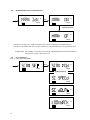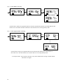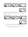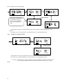
1
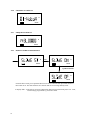
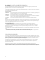
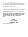
I.1.1.1 Pro
i
PL5161 / PL5164
Operating Instructions
TABLE OF CONTENTS
I
FCC RF EXPOSURE COMPLIANCE REQUIREMENTS FOR OCCUPATIONAL USE ONLY............4
I.1
I.2
I.3
CAUTION VHF AND UHF RADIOS (PL5151/PL5164)........................................................................................... 4
CAUTION VHF RADIO (PL5151).............................................................................................................................. 4
CAUTION UHF RADIO (PL5164).............................................................................................................................. 4
II ABOUT TOPAZ3 ................................................................................................................................................5
III
ABOUT YOUR LEGACY PROLINE RADIOS...........................................................................................5
IV
UNPACKING AND CHECKING EQUIPMENT ........................................................................................6
V RADIO CONTROL BUTTONS / OPERATION FEATURES .......................................................................7
VI
GETTING STARTED.....................................................................................................................................8
VI.1
VI.2
VI.3
VI.4
VI.5
VI.6
VII
CHARGING THE NIMH BATTERY PACK............................................................................................................. 8
ATTACHING AND REMOVING THE BATTERY PACK ..................................................................................... 8
INSTALLING THE ANTENNA.................................................................................................................................. 9
INSTALLING THE BELT CLIP ................................................................................................................................ 9
INSTALLING THE SPEAKER MICROPHONE JACK COVER........................................................................... 9
ATTACHING THE OPTIONAL SPEAKER MICROPHONE ................................................................................ 9
RADIO OPERATION...................................................................................................................................10
VII.1
VIII
VIII.1
VIII.2
VIII.3
VIII.4
VIII.5
VIII.6
VIII.7
VIII.8
VIII.9
VIII.10
VIII.11
VIII.12
VIII.13
VIII.14
VIII.15
VIII.16
VIII.17
IX
POWER ON................................................................................................................................................................. 13
CHANNEL CHANGE ................................................................................................................................................ 13
TRANSMIT ................................................................................................................................................................. 13
CHANNEL OPTION VIEW ...................................................................................................................................... 13
LOW BATTERY......................................................................................................................................................... 13
CHANNEL OPTION, SYSTEM OPTION & DISPLAY OPTION SETTING...................................................... 16
CHANNEL OPTION SETTING................................................................................................................................ 17
RX/TX TONE OPTION SETTING........................................................................................................................... 18
NO TONE SELECT.................................................................................................................................................... 18
CTCSS TONE SELECT......................................................................................................................................... 19
DCS TONE SELECT ............................................................................................................................................. 19
INVERT DCS TONE SELECT ............................................................................................................................. 20
TX OUTPUT POWER HIGH/LOW SETTING .................................................................................................. 20
NORMAL SCAN LIST ON/OFF SETTING........................................................................................................ 21
PRIORITY SCAN LIST ON/OFF SETTING ...................................................................................................... 21
TWO-TONE OPTION SETTING......................................................................................................................... 22
SYSTEM OPTION SETTING .........................................................................................................................23
X.1
X.2
X.3
X.4
X.5
X.6
X.7
X.8
X.9
2
TONE SIGNALING ............................................................................................................................................... 11
SCAN MODES........................................................................................................................................................ 11
NORMAL CHANNEL SCAN................................................................................................................................ 11
PRIORITY SCAN TX ............................................................................................................................................ 11
PRIORITY LOOK BACK SCAN ......................................................................................................................... 11
PRIORITY SELECT SCAN .................................................................................................................................. 11
VACANT CHANNEL SCAN................................................................................................................................. 11
NUISANCE DELETE ............................................................................................................................................ 11
BUSY CHANNEL LOCKOUT.............................................................................................................................. 11
MARKED IDLE ................................................................................................................................................. 11
TX DELAY ......................................................................................................................................................... 12
TIME-OUT-TIMER (TOT)............................................................................................................................... 12
TIME-OUT-TIMER PENALTY (TX INHIBIT)............................................................................................. 12
BATTERY SAVE ............................................................................................................................................... 12
LOW BATTERY WARNING ........................................................................................................................... 12
TWO-TONE DECODE...................................................................................................................................... 12
VOX (VOICE OPERATED X-MIT) ................................................................................................................ 12
MODE OPERATION AND FUNCTION SET UP .....................................................................................13
IX.1
IX.2
IX.3
IX.4
IX.5
IX.6
IX.7
IX.8
IX.9
IX.10
IX.11
IX.12
IX.13
IX.14
IX.15
IX.16
X
POWER ON / TRANSMIT.................................................................................................................................... 10
RADIO FUNCTIONS................................................................................................................................11
SYSTEM OPTION MENU DISPLAY FORMAT.................................................................................................... 23
BEEP TONE ON/OFF SETTING.............................................................................................................................. 24
VOX OPTION ON/OFF SETTING........................................................................................................................... 24
VOX SENSITIVITY SETTING................................................................................................................................. 25
TIME-OUT-TIMER SETTING................................................................................................................................. 25
TOT PENALTY SETTING........................................................................................................................................ 26
BUSY CHANNEL LOCK OUT ON/OFF SETTING............................................................................................... 26
MARKED IDLE OUT ON/OFF SETTING.............................................................................................................. 27
SCAN SETTING ......................................................................................................................................................... 27
X.9.1
X.9.2
X.9.3
X.9.4
X.9.5
X.9.6
X.10
X.11
X.12
X.13
X.14
X.15
X.16
X.17
X.18
X.19
X.20
X.21
X.22
XI
XII
XIII
XIV
3
SCAN SETTING MENU.............................................................................................................................................................. 27
SCAN MODE SETTING ............................................................................................................................................................. 28
SCAN SPEED TIME SETTING.................................................................................................................................................. 28
SCAN DELAY TIME SETTING ................................................................................................................................................ 29
LOOK BACK TIME SETTING.................................................................................................................................................. 29
PRIORITY SCAN SETTING ...................................................................................................................................................... 30
TX DELAY ON/OFF SETTING................................................................................................................................ 30
POWER SAVE SETTING ......................................................................................................................................... 31
POWER SAVE ON TIME SETTING ....................................................................................................................... 31
POWER SAVE OFF TIME SETTING ..................................................................................................................... 32
POWER SAVE DELAY TIME SETTING ............................................................................................................... 32
CLEAR TO TALK ON/OFF SETTING ................................................................................................................... 33
ROGER BEEP ON/OFF SETTING .......................................................................................................................... 33
DISPLAY OPTION SETTING .................................................................................................................................. 34
CHANNEL DISPLAY FORMAT SETTING ........................................................................................................... 34
NAME DISPLAY ........................................................................................................................................................ 34
CHANNEL NO. DISPLAY ........................................................................................................................................ 35
FREQUENCY DISPLAY ........................................................................................................................................... 35
DISPLAY SLIDE ON/OFF SETTING...................................................................................................................... 35
LICENSING, SAFETY AND SERVICE INFORMATION ......................................................................36
MAINTENANCE...........................................................................................................................................36
SOFTWARE COPYRIGHTS...................................................................................................................36
TOPAZ3 / LEGACY PRODUCT WARRANTY ....................................................................................37
I
FCC RF EXPOSURE COMPLIANCE REQUIREMENTS FOR OCCUPATIONAL USE
ONLY
The Federal Communications Commission (FCC), with its action in General Docket 93-62, November 7, 1997, has
adopted a safety standard for human exposure to Radio Frequency (RF) electromagnetic energy emitted by FCC
regulated equipment. Topaz3 / Legacy subscribes to the same safety standard for the use of its products. Proper
operation of this radio will result in user exposure far below the Occupational Safety and Health Act (OSHA) and
Federal Communications Commission limits.
I.1
CAUTION VHF AND UHF RADIOS (PL5151/PL5164)
DO NOT transmit for more than 50% of total radio use time (50% duty cycle). Transmitting more than
50% of the time can cause FCC RF exposure compliance requirements to be exceeded.
•
•
•
•
I.2
CAUTION VHF RADIO (PL5151)
•
I.3
This device has been approved for use, at a maximum duty factor of 50%, using the specific
belt clip and leather belt-holster tested for body-worn SAR compliance. Other belt clips or
body-worn accessories may not comply and should be avoided. ALWAYS use authorized
accessories: antennas, batteries, belt clips, speaker microphones, etc.
CAUTION UHF RADIO (PL5164)
•
4
This radio is NOT approved for use by the general population in an uncontrolled
environment. This radio is restricted to occupational use, work related operations only
where radio operator must have the knowledge to control the user’s exposure conditions for
satisfying the higher exposure limit allowed for occupational use.
When transmitting, hold the radio in a vertical position with its microphone 2 inches (5 cm)
away from your mouth.
The radio is transmitting when the red LED on the front of the radio is illuminated. You can
cause the radio to transmit by pressing the PTT bar on the radio.
These are required operating configurations for meeting FCC RF exposure compliance.
Failure to observe these restrictions mean violation.
This device has been approved for use, at a maximum duty factor of 50%, using the specific
plastic belt clip and/or leather belt-holster (ACC-304) tested for body-worn SAR compliance.
Other belt clips or body-worn accessories may not comply and should be avoided. ALWAYS
use authorized accessories: antennas, batteries, belt clips, speaker microphones, etc.
II
ABOUT TOPAZ3
Topaz3 is the exclusive supplier of Maxon®, Legacy and TruTalk brand communication products.
Our product line ranges from FCC licensed two-way radios suitable for Business and Industry (B&I) markets like
farm, government, law enforcement, utility, etc. to consumer communications equipment for recreational and lightduty business markets.
Product offerings include a variety of UHF and VHF handheld and mobile radios, repeaters and RF link modules as
well as FRS (Family Radio Service), GMRS (General Mobile Radio Service) radios, MURS (Multi User Radio
Service) radios, Citizen’s Band radios and weather monitors.
Available accessory items include a variety of carrying cases, spare batteries, desktop and mobile chargers,
ear bud speaker microphones and more for each radio model.
For additional information on our product line, visit our website: www.topaz3.com
III
ABOUT YOUR LEGACY PROLINE RADIOS
The Legacy ProLine models PL5161 (VHF) and PL5164 (UHF) are fully programmable, synthesized radios
featuring:
• 16 Channels of operation
• 8 Character alphanumeric display
• 2 Watts or 5 Watts output power
• Channel scan
• 38 Standard and 11 non-standard CTCSS tones
• 104 DCS Codes
• Two Tone Decode
• Approved to MIL-STD810F Specifications
• Scan channel delete
• Busy channel lockout
• Programmable CTCSS / DCS tones, wide/narrow channel spacing, and two-tone decode
• TX Inhibit
• Die-cast aluminum frame, polycarbonate cabinet
• Locking single-pin accessory connector
• Battery save circuitry
• Tri-color status LED
• Body-worn accessories (refer to section I)
To assure satisfaction from the radio, we urge you to thoroughly read the operation and function information
in this manual before operating your ProLine Series radio.
Application of some of the functions described in these Operating Instructions are determined by the system you
use. Your radio communications Dealer will program the radio so that you have the greatest number of functions
possible relative to your needs. Should you have questions regarding the operation of the radio, please consult with
your radio communications Dealer, or contact the Topaz3
Customer Service Department: 1-800-821-7848, Ext. 499.
5
IV
UNPACKING AND CHECKING EQUIPMENT
Carefully unpack the radio and its accessories. Use the item list below to identify the components included
in the product packaging, to ensure that no items are discarded in the packing materials.
Radio Body
Antenna
Battery Charger (with plastic spacer stored in charger base)
AC Adapter
NiMH Battery Pack
Speaker Microphone Jack Cover
Belt Clip (as depicted for Model PL5161 only; Model PL5164 requires a
plastic belt clip which is not depicted)
Screw Set
Operating Instructions
If any items are missing or damaged, you should
contact the Topaz3 Customer Service Department
for assistance: 1-800-821-7848, Ext. 499.
6
V
RADIO CONTROL BUTTONS / OPERATION FEATURES
A. Push-To-Talk (P-T-T) button (left side of radio) Press and hold while speaking into the radio microphone,
release to listen to incoming messages
B. Monitor button (left side of radio) Press and hold to turn radio squelch off. Release to turn squelch back on.
C. Microphone (front of radio)
D. Speaker (front of radio)
E. Channel switch (top panel of radio)
F. LED Indicator (top panel of radio) Identifies transmit (red), receive (signal only) orange, (signal + TONE)
green, setup mode (orange), battery low (flashing red)
G. Power / volume control (top panel of radio) Powers radio on and adjusts radio volume
H. Speaker microphone jack (right side of radio)
I. Mode button (front of radio)
J. Up/Down select buttons (front of radio)
K. Scan button(front of radio)
G
E
F
H
A
K
B
I
J
C
D
7
VI
GETTING STARTED
VI.1
CHARGING THE NIMH BATTERY PACK
You will need to charge the battery pack fully before initial use. For best results from your charging cycle, follow
these tips:
•
•
•
•
•
•
Ensure the ambient temperature is between 41 and 104° F (5 and 40° C) while charging. Temperatures
outside this range may not fully charge the battery.
Always switch OFF the transceiver equipped with a NiMH battery pack before charging. Using the radio
during the charging cycle will hinder correct charging.
Do not recharge the battery pack if it is already fully charged. Doing so may cause the life of the battery
pack to shorten or the battery pack may be damaged.
If the battery is stored for 2 months or more, it is a good idea to complete the charge / discharge cycle two
or three times to allow the battery capacity to return to normal.
Never dispose of the battery in fire - it can explode causing personal injury.
Never attempt to disassemble the battery or remove its case material or charging contacts. Do not short the
battery terminals.
NOTE: The first few uses from the battery will not be at “normal” capacity. After repeating the charge /
discharge cycle two or three times, the battery capacity will increase to provide full capacity.
1.
2.
3.
4.
Plug the AC adapter cable in the adapter jack located on the rear of the charger, then into an AC outlet.
Slide the NiMH battery pack (or the radio equipped with a NiMH battery pack) into the charging slot.
Ensure that the metal contacts on the battery pack come in contact with the charging terminals.
When charging the NiMH battery pack alone, insert the provided plastic spacer (stored in charger base)
into the charging well, then insert the battery pack.
5. The charger LED will light to advise that charging has begun. Charge the standard battery pack for
9 hours. THEN REMOVE THE PACK OR RADIO FROM THE CHARGER.
IMPORTANT NOTE: The ACC-410 SLOW charger DOES NOT TURN OFF AUTOMATICALLY after
the charging cycle has been completed. Damage to the battery or reduced battery life may result if charged in
excess of the recommended charging time.
VI.2 ATTACHING AND REMOVING THE BATTERY PACK
NOTE: After recharging the battery pack, REMOVE IT FROM THE CHARGER. Charging the battery pack for
more than 5 days may reduce the battery life.
The battery pack life is over when its operating time decreases even though it is fully and correctly charged. Replace
the pack with the manufacturer’s recommended model.
Average battery pack life from the supplied 750 mAh battery is 8+ hours; the optional 1350 mAh battery, 10+ hours.
This service time is calculated using 90% standby, 5% transmit and 5% receive time and 5W operation.
After charging the battery pack as described, you are ready to install it to the radio body. Simply;
1. Match the four grooves of the battery pack with the guides on the back of the radio.
2. Slide the battery pack up along the back of the radio until the release latch locks.
To remove the battery pack, push down on the release latch and slide the pack downward, and away from the
radio.
8
VI.3 INSTALLING THE ANTENNA
Screw the antenna into the connector on the top of the radio by holding the antenna at its base and turning it
clockwise
until seated. Do not overtighten.
The antenna should never be used to carry your radio, or as a base to clip radio accessories. Misuse of the antenna
can cause damage, and reduce your radio’s performance.
VI.4 INSTALLING THE BELT CLIP
We recommend that the belt clip is installed on the radio. It keeps the radio from coming in contact with hot
surfaces, and away from your body if heat build-up occurs with excess transmissions.
Use the two supplied screws to install the belt clip. If a replacement is needed, use a screw designed to the exact
specifications as the original, to prevent accidental contact with internal circuitry, or possible personal injury. Never
use glue in conjunction with the provided screws. Some of the glue's components may crack the radio back panel
causing radio damage and possible personal injury.
VI.5 INSTALLING THE SPEAKER MICROPHONE JACK COVER
If you are not using an accessory, install the provided cover over the speaker microphone jack using the screw
supplied. This will keep the radio water resistant.
VI.6 ATTACHING THE OPTIONAL SPEAKER MICROPHONE
1. Insert the speaker microphone jack into the radio.
2. Use the thumbscrew attachment on the speaker microphone to make connection to the radio.
NOTE: The radio is not fully water resistant while the speaker microphone is attached.
9
VII RADIO OPERATION
VII.1
POWER ON / TRANSMIT
Power on the radio by turning the power / volume control clockwise out of detent. You will hear a confirmation tone
on power-up. To check the radio volume, press and hold the monitor button then rotate the control to desired volume
level.
Use the channel switch to choose the desired channel. Press the monitor button to check the channel for activity. To
avoid interrupting another user, make sure the channel is clear before you begin transmitting.
To transmit, place the radio microphone approximately 2” (5 cm) from your mouth. Press and hold the PTT bar
while speaking in a normal tone. Release the PTT bar when you are finished speaking; the radio will be placed into
receive mode.
When the battery pack voltage becomes too low for operation to continue, a tone will sound, LOW Batt will show in
the display, the LED will blink red and the battery icon located in the lower left corner of the display will flash
empty. The radio will allow only one more transmission - change or charge your battery. Refer to the “Low Battery
Warning” section of this manual.
10
VIII RADIO FUNCTIONS
VIII.1 TONE SIGNALING
To help block out unwanted calls to your radio, the PL5151 and PL5164 can be programmed by your radio
communications
Dealer to look for tones.
VIII.2 SCAN MODES
Scanning is a Dealer programmable feature that allows you to monitor a number of channels. Your radio
communications Dealer will help you define a scanning mode and your channel "scan list".
Once the scan list has been established, initiate scan by pressing the SCAN button. The SCAN icon will show in the
upper left corner of the display to confirm radio scanning.
VIII.3 NORMAL CHANNEL SCAN
If a conversation is detected on any of the channels in the scan list, the radio will stop on that channel and you will
be able to hear the conversation. In normal scan, you will be able to transmit on that active channel during the
programmable scan delay time. (The scan delay time is the amount of time the radio will stay on that channel once
activity has ceased. Dealer programmable, 4 - 7 seconds is typical).
The radio will resume scanning once the scan delay time has expired, and will continue to scan until the channel is
changed. In scan mode, if radio power is turned off and on, the radio will return to the scan mode until a channel is
changed.
VIII.4 PRIORITY SCAN TX
A single channel may be programmed as the "Priority" channel. The radio will constantly monitor this channel
while scanning and when stopped on an active channel. If a call is detected on the priority channel, the radio will
automatically move to, and remain on, the priority channel. Priority channel activity takes precedence over all
other conversations. During the scan mode if a PTT is initiated the radio will transmit on the priority channel.
VIII.5
PRIORITY LOOK BACK SCAN
A single channel may be programmed as the "Priority" channel. The radio will constantly monitor this channel
while scanning and when stopped on an active channel. If a call is detected on the priority channel “during a
conversation”, the radio will automatically move to, and remain on, the priority channel. Priority channel activity
takes precedence over all other conversations.
VIII.6
PRIORITY SELECT SCAN
The selected channel becomes the priority channel. As you change the channel that channels frequency will
become your new priority channel. Priority channel activity takes precedence over all other conversations.
VIII.7
VACANT CHANNEL SCAN
The radio will automatically scan for the first open channel. Once a channel is found normal scan operation will
take place. All radios you intend to communicate must be programmed for this same scan function.
VIII.8 NUISANCE DELETE
During receiving a signal or scan delay time, if the monitor button is pressed, the current receiving channel is
deleted in scan list and is no longer scanned. When the power is turned off and on, the deleted channel is restored to
the scan list.
VIII.9 BUSY CHANNEL LOCKOUT
When the RX signal is being received, the radio’s transmitter is disabled. Dealer programming makes this feature
active or disabled.
VIII.10
MARKED IDLE
When used in conjunction with busy channel lockout, the transmitter is allowed to operate as long as valid RX tone
is received. Dealer programming makes this feature active or disabled.
11
VIII.11
TX DELAY
The TX will remain active for approximately 180 seconds even though P-T-T button is released when using CTCSS
tones.
This eliminates squelch tail by sending CTCSS turn-off code (No Tone TX).
VIII.12
TIME-OUT-TIMER (TOT)
The purpose of the time-out-timer is to prevent any single person from using a channel for an extended period. The
time-out-time can be programmed from 10 seconds to 990 seconds by your radio Dealer. When active the TOT icon
will show in the display.
VIII.13
TIME-OUT-TIMER PENALTY (TX INHIBIT)
When TOT is applied, transmission will be inhibited after time-out-time time expires. This TX inhibit time can be
selected and programmed by your Dealer from 1 second to 100 seconds. For instance, when TOT is set to 3 minutes
and TOT penalty is set to 5 seconds, if you continuously transmit for 3 minutes, the radio will stop transmitting. A
tone will sound with each
PTT bar press until the 5-sec. TX inhibit time expires.
Press the P-T-T bar after the TX inhibit time expires to resume transmitting.
VIII.14
BATTERY SAVE
The battery save function decreases the amount of power used when a signal is not being received and no operations
are being performed (no bars are being pressed, no controls are being used, etc.)
When the channel is not busy and no operation is performed, battery save is enabled. When an operation is
performed, or
a signal is received, battery save is disabled.
VIII.15
LOW BATTERY WARNING
When the battery power goes below a pre-determined value, the LED will blink red and a tone sounds. The radio
will then allow only one more transmission. After that, the transceiver will stop transmitting. Replace or recharge
the battery pack.
VIII.16
TWO-TONE DECODE
Each channel can be programmed with two-tone decode by your radio communications Dealer. Two-tone selections
are: Individual Call, Group Call and Super Group Call.
VIII.17 VOX (VOICE OPERATED X-MIT)
Allows your radio to PTT with the sound of your voice for hands free operation. Your radio has VOX sensitivity
adjustment for noisy or windy conditions. VOX icon will be displayed when option is turned on.
12
IX
MODE OPERATION AND FUNCTION SET UP
Depending on how your dealer has programmed your radio you may be able to change certain mode and functions
of your radio. Please consult your dealer regarding what functions are available with your radio.
The following information is a menu tree with brief description and display reading of how to access radio mode
functions.
All functions are accessed or turned off or on by pressing the mode button. Using the up (∧) or down (∨) buttons
move your radio display up and down each function feature. To exit press the PTT or wait for the radio to time out.
IX.1
POWER ON
Power on the radio by turning the power/volume control clockwise out of detent. You will hear a confirmation
tone on power-up. When Power-on, all character and icon are displayed for around 0.7 sec. A beeps is sounded
when the radio is ready to enter normal operation mode.
* When Power-On, it checks the last Memory and if data is wrong, it will indicate the below display and beep
an error tone. The radio enters normal operation with two beeps.
IX.2
CHANNEL CHANGE
Rotate Channel Knob to select the channel among 16 channels your display will change with each channel
selection. Your channel display reading will vary depending on how your dealer programmed each channel
description.
IX.3
TRANSMIT
- Press PTT button to transmit. If PTT button is released, the radio returns to receive mode. Both TX and
RX mode are indicated by display icons.
When VOX option is set and voice is input, the radio transmits the signal. If voice input stops, the radio
maintains TX for around 2 sec. if there is no voice input, the radio returns to receive mode.
IX.4
CHANNEL OPTION VIEW
- In receiving mode, if the Monitor button is pressed for more than 2 sec., the RX tone option and the TX
tone option for each channel selected will display for one sec.
H
H
BEEP
BEEP
IX.5
LOW BATTERY
- If Battery voltage goes under a predetermined value a Low Battery error message is shown for 2 sec.
The battery Icon will flash.
H
BEEP
13
FIGURE IX-1:
MENU TREE
Rx Stand-By Mode
Each Channel Setting
System Option Setting
Display Option Setting
Each Channel
Setting
Tone
Option
Rx Tone
Tx Tone
CTCSS
1 ~ 49
DCS
023 ~ 754
Invert DCS
023 ~ 754
No Tone
CTCSS
1 ~ 49
DCS
023 ~ 754
Invert DCS
023 ~ 754
Tx Output Power High/Low
Power High/Low
Normal Scan List
Normal Scan On/Off
Priority Scan List
Priority Scan On/Off
Two-Tone Option
14
No Tone
Individual Tone
On/Off
Group Tone
On/Off
Super Group Tone
On/Off
System Option Setting
Beep Tone
Beep On/Off
VOX Option
VOX On/Off
VOX Sensitivity
Level 1 ~ Level 3
Time Out Timer
TOT On
1 ~ 990 sec
TOT Off
TOT Penalty
Penalty On
1 ~ 100 sec
Penalty Off
Busy Lock
Busy Lock On/Off
Marked Idle
Marked Idle On/Off
Scan Set
Scan Mode
Normal Scan Tx
Priority Scan Tx
Priority Look Back
Scan
Priority Select Scan
Vacant Channel Scan
Scan Speed Time
50 ~ 500 msec
Scan Delay Time
1 ~ 30 sec
Look Back Time
1 ~ 10 sec
Priority Scan
On
Priority Channel 1 ~ 16
Off
15
Tx Delay
On/Off
Power Save
On
P/S On Time
50 ~ 2000
Off
P/S Off Time
50 ~ 2000
P/S Delay Time
1 ~ 10
Clear To Talk
On/Off
Roger Beep
On/Off
Display Option Setting
Channel Display Format
Name Character Display
Channel No. Display
Frequency Display
Slide Set
Slide On
Slide Off
IX.6
16
CHANNEL OPTION, SYSTEM OPTION & DISPLAY OPTION SETTING.
- To enter Menu Setting, press and release Mode button in receive mode or stand-by mode.
- In Menu Setting, press Up/Down buttons to move in an up or down direction in the current menu display
setting.
- To enter the Sub-menu of Setting Menu, press mode button, press Up/Down buttons to move in an up or
down direction in the displayed Sub-menu setting. To turn on or off a Sub-menu setting press and release
the mode button. The radio will save the setting and exit to receiving standby mode.
- If PTT button is pressed, the radio exits to receiving standby mode.
- If Monitor button is pressed, the radio will return to the previous Menu setting displayed.
IX.7
CHANNEL OPTION SETTING
FIGURE IX-2:
EACH CHANNEL MENU DISPLAY FORMAT
H
H
I.2
BEEP
BEEP
Up/Down buttons
H
BEEP
H
BEEP
H
BEEP
H
BEEP
17
IX.8
RX/TX TONE OPTION SETTING
Each Channel Option Menu Setting
H
I.3
Mode
H
BEEP
O
BEEP
Rx Tone Menu Setting
Mode
H
H
BEEP
BEEP
Up/Down buttons
Up/Down buttons
H
H
BEEP
BEEP
Tx Tone Menu Setting
Up/Down buttons
H
BEEP
Up/Down buttons
H
BEEP
IX.9
NO TONE SELECT
Mode
H
BEEP
Under the above, if MODE button or PTT Button is pressed, it sets No tone for RX or TX Tone option and
Exits to receiving stand-by mode.
18
IX.10 CTCSS TONE SELECT
I.4
H
Mode
BEEP
H
BEEP
Up/Down buttons
H
BEEP
Under the above mode, press Up/Down buttons to select desired CTCSS Tone and then press Mode button or
PTT button to set RX or TX tone option. The radio will then save selection and exit to receiving stand-by
mode.
IX.11 DCS TONE SELECT
Mode
H
BEEP
Mode
H
BEEP
Up/Down buttons
H
BEEP
Under the above mode, press Up/Down buttons to select desired DCS Tone and then press Mode button or PTT
button to set RX or TX tone option. The radio will then save selection and exit to receiving stand-by mode.
19
IX.12 INVERT DCS TONE SELECT
Mode
H
Mode
H
BEEP
BEEP
Up/Down buttons
H
BEEP
Under the above mode, press Up/Down buttons to select desired DCS Tone and then press Mode button or PTT
button to set RX or TX tone option. The radio will then save selection and exit to receiving stand-by mode.
IX.13 TX OUTPUT POWER HIGH/LOW SETTING
H
BEEP
H
Mode
BEEP
Up/Down buttons
H
BEEP
Under the above mode, press Up/Down buttons to select desired Output Power and then press Mode button
Or
PTT button to set the output power to 1W or 5W for the current channel. The radio will then save selection and exit
to receiving stand-by mode.
20
IX.14 NORMAL SCAN LIST ON/OFF SETTING
MOde
H
H
BEEP
BEEP
Up/Down buttons
H
BEEP
Under the above mode, press Up/Down buttons to select On or Off and then press Mode buttons or PTT button to
set the scan option On or Off for the current channel. The radio will then save selection and exit to receiving standby mode.
During SCAN the radio scans only channels, which are set "On".
IX.15 PRIORITY SCAN LIST ON/OFF SETTING
H
BEEP
H
Mode
BEEP
Up/Down buttons
H
BEEP
Under the above mode, press Up/Down buttons to select On or Off and then press Mode button or
PTT button to set the priority scan option On or Off for the current channel.
** If Priority Scan option of “System Option” menu is on, Priority scan works only when the channel
selector is positioned to the channel with "PSCAN ON".
21
IX.16 TWO-TONE OPTION SETTING
H
BEE
Mode
Mode
H
H
BEE
BEE
H
BEE
I.5
H
M
O
H
BEE
BEE
Up/Down buttons
H
BEE
Mode
H
H
BEE
BEE
Up/Down buttons
H
BEE
Under the above mode, press Up/Down buttons to select On or Off and then press Mode button or
PTT button to set 2-Tone Option (Individual, Group, Super-Group) On or Off for the current channel.
The radio will then save selection and exit to receiving stand-by mode.
** Individual, Group, Super-Group, Tone A, and Tone B frequency and timing are dealer programmed.
22
X
X.1
SYSTEM OPTION SETTING
SYSTEM OPTION MENU DISPLAY FORMAT
H
Mode
BEEP
BEEP
H
BEEP
H
BEEP
H
BEEP
H
BEEP
H
BEEP
H
BEEP
23
H
H
BEEP
H
BEEP
H
BEEP
H
BEEP
H
BEEP
H
BEEP
X.2
BEEP TONE ON/OFF SETTING
H
Mode
BEEP
H
BEEP
Up/Down buttons
H
BEEP
Under the above mode, press Up/Down buttons to select On or Off and then press Mode button or
PTT button to set Beep Tone On or Off. The radio will then save selection and exit to receiving stand-by
mode.
X.3
VOX OPTION ON/OFF SETTING
H
BEEP
H
Mode
BEEP
Up/Down buttons
H
BEEP
Under the above mode, press Up/Down buttons to select On or Off and then press Mode button or
PTT button to set VOX Option On or Off. The radio will then save selection and exit to receiving stand-by
mode.
24
X.4
VOX SENSITIVITY SETTING
H
Mode
H
BEEP
BEEP
Up/Down buttons
H
BEEP
H
BEEP
Under the above mode, press Up/Down buttons to select desired level and then press Mode button or
PTT button to set VOX sensitivity level. The radio will then save selection and exit to receiving stand-by
mode.
X.5
TIME-OUT-TIMER SETTING
Mode
Mode
H
H
BEE
BEE
H
BEE
Up/Down buttons
In this mode, if MODE button
or PTT Button is pressed,
TOT function is disabled and
exits to receiving stand-by
mode.
H
BEE
H
BEE
Under the above mode, press Up/Down buttons to select desired time and then press Mode button or
PTT button to set T-O-T time. The radio will then save selection and exit to receiving stand-by mode.
.
** T-O-T : This function inhibits TX after a set time.
25
X.6
TOT PENALTY SETTING
Mode
Mode
H
H
H
BEE
BEE
BEE
Up/Down buttons
In this mode, if MODE button
or PTT Button is pressed,
TOT penalty function is
disabled and exits to receiving
stand-by mode.
H
BEE
H
BEE
Under the above mode, press Up/Down buttons to select desired time and then press Mode button or
PTT button to set T-O-T penalty time. The radio will then save selection and exit to receiving stand-by
mode.
** TOT Penalty : If the radio transmits over a set time, it will beep an T-O-T error tone and the radio
will only receive a signal for the penalty time. (TX inhibited for this time.)
X.7
BUSY CHANNEL LOCK OUT ON/OFF SETTING
H
H
Mode
BEEP
BEEP
Up/Down buttons
H
BEEP
Under the above mode, press Up/Down buttons to select On or Off and then press Mode button or
PTT button to set Busy Channel Lock Out. The radio will then save selection and exit to receiving stand-by
mode.
.
** Busy Channel Lock Out : If the channel is busy, it inhibits transmission.
26
X.8
MARKED IDLE OUT ON/OFF SETTING
H
H
Mode
BEEP
BEEP
Up/Down buttons
H
BEEP
Under the above mode, press Up/Down buttons to select On or Off and then press Mode button or
PTT button to set Marked Idle Out. The radio will then save selection and exit to receiving stand-by mode.
** Marked Idle : If the channel is set by Busy Lock and TX is inhibited during RX, this function allows a
TX when it is CTCSS or DCS correct call.
X.9
SCAN SETTING
X.9.1 Scan Setting Menu
II
Mode
H
BEEP
BEEP
Up/Down buttons
III
BEEP
H
BEEP
H
BEEP
27
X.9.2 Scan Mode Setting
H
Mode
H
Mode
H
BEE
BEE
BEE
Up/Down buttons
H
BEE
Under the above mode, press Up/Down buttons to select the desired Scan operation. Press Mode button or PTT
button to set a scan mode. The radio will then save selection and exit to receiving stand-by mode.
X.9.3 Scan Speed Time Setting
H Mode
HMode
BEE
BEE
H
BEE
H
BEE
Under the above mode, press Up/Down buttons to select desired time and then press Mode button or
PTT button to set. The radio will then save selection and exit to receiving stand-by mode.
** Scan Speed Time : In SCAN, this is the time to stay on the channel before moving to another channel
when there is no signal.
28
X.9.4 Scan Delay Time Setting
VMode
IV Mode
H
BEE
BEE
BEE
Up/Down buttons
H
BEE
Under the above mode, press Up/Down buttons to select desired time and then press Mode button or PTT button to
set. The radio will then save selection and exit to receiving stand-by mode.
Scan Delay Time : In SCAN, this is the stand-by time to stay on the channel after the receiving signal stops or after
transmitting.
X.9.5 Look Back Time Setting
H MOde
BEE
H Mode
H
BEE
BEE
Up/Down buttons
H
BEE
Under the above mode, press Up/Down buttons to select desired time and then press Mode button or
PTT button to set. The radio will then save selection and exit to receiving stand-by mode.
** Look Back Time : In Priority SCAN mode, this is the interval time to check the priority channel when
the radio receives a signal on a non- priority channel.
29
X.9.6 Priority Scan Setting
Mode
H
H
BEE
Mode
H
BEE
BEE
Up/Down buttons
In this mode, if MODE button
or PTT Button is pressed,
Priority Scan is disabled and
exits to receiving stand-by
mode.
H
H
BEE
BEE
Under the above mode, press Up/Down buttons to select desired priority channel and then press Mode
button or
PTT button to set. The radio will then save selection and exit to receiving stand-by mode.
X.10
TX DELAY ON/OFF SETTING
H
VI
H
Mode
BEEP
Up/Down buttons
H
BEEP
Under the above mode, press Up/Down buttons to select On or Off and then press Mode button or
PTT button to set. The radio will then save selection and exit to receiving stand-by mode.
** Tx Delay : This function is to remove Squelch tail of receiving Radio by creating a CTCSS Turn-Off
(No Tone) during 180msec after TX is completed if TX tone option is set by CTCSS
Option.
30
X.11
POWER SAVE SETTING
H Mode
H Mode
BEE
H
BEE
BEE
Up/Down buttons
H
In this mode, if MODE button
or PTT Button is pressed,
Power Save is disabled and
exits to receiving stand-by
mode.
H
BEE
BEE
H
BEE
X.12
POWER SAVE ON TIME SETTING
H Mode
BEE
H
Mode
H
BEE
BEE
Up/Down buttons
H
BEE
Under the above mode, press Up/Down buttons to select the desired time and then press Mode button or
PTT button to set. The radio will then save selection and exit to receiving stand-by mode.
31
X.13
POWER SAVE OFF TIME SETTING
H
Mode
H
Mode
H
BEE
BEE
BEE
Up/Down buttons
H
BEE
Under the above mode, press Up/Down buttons to select the desired time and then press Mode button or
PTT button to set. The radio will then save selection and exit to receiving stand-by mode.
X.14
POWER SAVE DELAY TIME SETTING
H Mode
BEE
H Mode
H
BEE
BEE
Up/Down buttons
H
BEE
Under the above mode, press Up/Down buttons to select the desired time and then press Mode button or
PTT button to set. The radio will then save selection and exit to receiving stand-by mode.
32
X.15
CLEAR TO TALK ON/OFF SETTING
H
H
Mode
BEEP
BEEP
Up/Down buttons
H
BEEP
Under the above mode, press Up/Down buttons to select On or Off and then press Mode button or
PTT button to set. The radio will then save selection and exit to receiving stand-by mode.
** Clear To Talk : This function issues a beep tone when pressing the PTT Button, letting you know
speaking may begin.
X.16
ROGER BEEP ON/OFF SETTING
H
VII
H
Mode
BEEP
Up/Down buttons
H
BEEP
Under the above mode, press Up/Down buttons to select On or Off and then press Mode button or
PTT button to set. The radio will then save selection and exit to receiving stand-by mode.
** Roger Beep : This function issues a beep tone after TX is completed to confirm the transmission
has finished.
33
X.17
DISPLAY OPTION SETTING
IX
H
H
Mode
BEEP
VIII
BEEP
Up/Down buttons
H
BEEP
X.18
CHANNEL DISPLAY FORMAT SETTING
H
H
Mode
BEEP
BEEP
Up/Down buttons
H
BEEP
H
BEEP
Under the above mode, press Up/Down buttons to select Display Format and then press Mode button or
PTT button to set. The radio will then save selection and exit to receiving stand-by mode.
X.19
NAME DISPLAY
H
BEEP
34
X.20
CHANNEL NO. DISPLAY
H
BEEP
X.21
FREQUENCY DISPLAY
H
BEEP
X.22
DISPLAY SLIDE ON/OFF SETTING
H
BEEP
H
Mode
BEEP
Up/Down buttons
H
BEEP
Under the above mode, press Up/Down buttons to select On or Off and then press Mode button or
PTT button to set. The radio will then save selection and exit to receiving stand-by mode.
** Display Slide : If the radio is not in TX or RX and no button is pressed and time passes over 1 min,
a slide message programmed by your dealer scrolls.
35
XI
LICENSING, SAFETY AND SERVICE INFORMATION
FCC Licensing
The Federal Communications Commission requires the operator of this radio be properly licensed under the
applicable Part and / or Parts of the FCC Rules and Regulations.
Consult with an authorized Topaz3 / Legacy radio communications Dealer, or contact the nearest FCC Field Office
for information about obtaining a license.
Safety Information
WARNING DO NOT hold the radio in such a manner that the antenna is next to, or touching, exposed parts of
the body, especially the face or eyes, while transmitting.
WARNING DO NOT allow children to operate transmitter-equipped radio equipment.
CAUTION DO NOT operate the radio near unshielded electrical blasting caps or in an explosive atmosphere,
unless it is a type especially designed and qualified for such use.
CAUTION DO NOT press and hold the transmit bar (P-T-T) when not actually wishing to transmit.
Service
DO NOT tamper with internal radio adjustments - damage to the equipment and / or improper operation may result.
There are no serviceable items inside the radio. It is recommended that you return the radio to a qualified Topaz3 /
Legacy radio communications Dealer for any service or repairs.
XII MAINTENANCE
Your Legacy radio is designed to be maintenance-free, and can be kept in good working condition by:
• Cleaning all external surfaces with a clean cloth, dampened in a mild solution of dishwasher and detergent
diluted in water. Apply the solution sparingly to avoid any moisture leaking into cracks or crevices - NEVER
submerge the radio. Use
a non-metallic brush if needed to dislodge stubborn particles. Dry the radio surface thoroughly with a soft, lint-free
cloth.
• DO NOT use solvents or spirits for cleaning - they may permanently damage the radio.
• Clean the battery and accessory jack contacts with a lint-free cloth to remove dirt, grease or foreign materials.
XIII SOFTWARE COPYRIGHTS
The Topaz3 / Legacy products described in these operating instructions may include copyrighted Topaz3 / Legacy
software programs stored in semi-conductor memories or other media. Laws in the United States and other countries
preserve for Topaz3 / Legacy certain exclusive rights for copyrighted software programs, including the exclusive
right to copy or reproduce in any form the copyrighted software program.
Accordingly, the copyrighted Topaz3 / Legacy software programs contained in the Topaz3 / Legacy product(s)
described in this operating instruction manual may not be copied or reproduced without the express written
permission of Topaz3, LLC.
Furthermore, the purchase of Topaz3 / Legacy products shall not be deemed to grant either directly or by
implication, estoppel, or otherwise, any license under the copyrights, patents or patent applications of Topaz3, LLC,
except for normal non-exclusive, royalty-free license to use that arises by operation of law in the sale of a product.
36
XIV TOPAZ3 / LEGACY PRODUCT WARRANTY
Topaz3, LLC (hereinafter, “Topaz3”) warrants that the Products and included accessories sold herein will be free from defects in workmanship or
materials under normal use and service for a period of two (2) years (one year for accessories) from the date of purchase by the original end user,
provided that the buyer has complied with the requirements stated herein. This warranty is offered to the initial end user and is not assignable or
transferable. Topaz3 is not responsible for any ancillary equipment which is attached to or used in conjunction with Topaz3 / Legacy products.
If the Product fails to function under normal use because of manufacturing defect(s) or workmanship during the two (2) years period following
the date of purchase, it will be replaced or repaired at Topaz3's option at no charge when returned to the place of purchase. The defective unit
must be accompanied by proof of the date of purchase in the form of a sales receipt.
The sole obligation of Topaz3 hereunder shall be to replace or repair the Product covered in this Warranty. Replacement, at Topaz3's option, may
include a similar or higher-featured product. Repair may include the replacement of parts or boards with functionally equivalent reconditioned or
new parts or boards. Replaced parts, accessories, batteries, or boards are warranted for the balance of the original time period. All replaced parts,
accessories, batteries or boards become the property of Topaz3.
Topaz3 shall have no obligation to make repairs or to cause replacement required through normal wear and tear or necessitated in whole or in part
by catastrophe, fault or negligence of the user, improper or unauthorized alterations or repairs to the Product, use of the Product in a manner for
which it was not designed, or by causes external to the Product. This warranty is void if the serial number is altered, defaced or removed.
The user is responsible for the payment of any charges or expenses incurred for the removal of the defective product from the vehicle or site of its
use, for the transportation of the product to the place of repair, for the return of the repaired / replaced product to the site of its use and for the
reinstallation of the product.
THE EXPRESS WARRANTIES CONTAINED HEREIN ARE IN LIEU OF ALL OTHER WARRANTIES, EITHER EXPRESSED OR
IMPLIED OR STATUTORY, INCLUDING, WITHOUT LIMITATION, ANY WARRANTY OF MERCHANTABILITY OR FITNESS
FOR A PARTICULAR PURPOSE.
FOR ANY PRODUCT WHICH DOES NOT COMPLY WITH THE WARRANTY SPECIFIED, THE SOLE REMEDY WILL BE
REPAIR OR REPLACEMENT. IN NO EVENT WILL TOPAZ3 BE LIABLE TO THE BUYER OR ITS CUSTOMERS FOR ANY
DAMAGES, INCLUDING ANY SPECIAL, INCIDENTAL, INDIRECT OR CONSEQUENTIAL DAMAGES,
OR FOR THE LOSS OF PROFIT, REVENUE OR DATA ARISING OUT OF THE USE OF OR THE INABILITY TO USE THE
PRODUCT.
This warranty is void for sales and deliveries outside of the U. S. A.
Topaz3, LLC
10828 NW Air World Drive
Kansas City, Missouri 64153
www.topaz3.com
Toll free: 800-821-7848
Phone: 816-891-6320 • Fax: 816-891-8815
Maxon is a registered tradename of Maxon America, Inc.
Printed in Korea
P/N: 680-090-xxxx
37