1
OWNER’S MANUAL
OWNER’S MANUAL
Before using this unit, carefully read
the sections entitled: “IMPORTANT
SAFETY INSTRUCTIONS” (page 2),
“USING THE UNIT SAFELY” (page 3),
and “IMPORTANT NOTES” (page 4).
These sections provide important information concerning the proper operation
of the unit. Additionally, in order to
feel assured that you have gained a
good grasp of every feature provided
by your new unit, Quick Start and
Owner’s Manual should be read in its
entirety.
The manuals should be saved and kept
on hand as a convenient reference.
For XP-60 Owners
Even though only the XP-80 model is
referred to in this manual and in the
Quick Start manual, all operations
are common to both the XP-80 and
XP-60.
Please substitute “XP-60” for each
occurrence of “XP-80” that you find
in this Owner's Manual and the
Quick Start.
01458056
’99-7-E3-51K
Copyright 1998 ROLAND CORPORATION
All rights reserved. No part of this publication
may be reproduced in any form without the written permission of ROLAND CORPORATION.
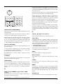
CAUTION
RISK OF ELECTRIC SHOCK
DO NOT OPEN
ATTENTION: RISQUE DE CHOC ELECTRIQUE NE PAS OUVRIR
CAUTION: TO REDUCE THE RISK OF ELECTRIC SHOCK,
DO NOT REMOVE COVER (OR BACK).
NO USER-SERVICEABLE PARTS INSIDE.
REFER SERVICING TO QUALIFIED SERVICE PERSONNEL.
The lightning flash with arrowhead symbol, within an
equilateral triangle, is intended to alert the user to the
presence of uninsulated “dangerous voltage” within the
product’s enclosure that may be of sufficient magnitude to
constitute a risk of electric shock to persons.
The exclamation point within an equilateral triangle is
intended to alert the user to the presence of important
operating and maintenance (servicing) instructions in the
literature accompanying the product.
INSTRUCTIONS PERTAINING TO A RISK OF FIRE, ELECTRIC SHOCK, OR INJURY TO PERSONS.
IMPORTANT SAFETY INSTRUCTIONS
SAVE THESE INSTRUCTIONS
For EU Countries
CAUTION
Danger of explosion if battery is
incorrectly replaced.
Replace only with the same or
equivalent type recommended by the
manufacturer.
Discard used batteries according to the
manufacturer’s instructions.
Apparatus containing
Lithium batteries
WARNING - When using electric products, basic precautions should always be followed, including the following:
1. Read all the instructions before using the product.
2. Do not use this product near water — for example, near a
bathtub, washbowl, kitchen sink, in a wet basement, or near
a swimming pool, or the like.
3. This product should be used only with a cart or stand that is
recommended by the manufacturer.
4. This product, either alone or in combination with an amplifier
and headphones or speakers, may be capable of producing
sound levels that could cause permanent hearing loss. Do
not operate for a long period of time at a high volume level
or at a level that is uncomfortable. If you experience any
hearing loss or ringing in the ears, you should consult an
audiologist.
5. The product should be located so that its location or position
does not interfere with its proper ventilation.
6. The product should be located away from heat sources such
as radiators, heat registers, or other products that produce
heat.
7. The product should be connected to a power supply only of
the type described in the operating instructions or as marked
on the product.
8. The power-supply cord of the product should be unplugged
from the outlet when left unused for a long period of time.
9. Care should be taken so that objects do not fall and liquids
are not spilled into the enclosure through openings.
10.The product should be serviced by qualified service
personnel when:
A. The power-supply cord or the plug has been damaged; or
B. Objects have fallen, or liquid has been spilled into the
product; or
C. The product has been exposed to rain; or
D. The product does not appear to operate normally or
exhibits a marked change in performance; or
E. The product has been dropped, or the enclosure
damaged.
11.Do not attempt to service the product beyond that described
in the user-maintenance instructions. All other servicing
should be referred to qualified service personnel.
VARNING
Explosionsfara vid felaktigt batteribyte.
Använd samma batterityp eller en
ekvivalent typ som rekommenderas av
apparattillverkaren.
Kassera använt batteri enligt
fabrikantens instruktion.
ADVARSEL
VAROITUS
Eksplosjonsfare ved feilaktig skifte av
batteri.
Benytt samme batteritype eller en
tilsvarende type anbefalt av
apparatfabrikanten.
Brukte batterier kasseres i henhold til
fabrikantens instruks joner.
Paristo voi räjähtää, jos se on
virheellisesti asennettu.
Vaihda paristo ainoastaan
laitevalmistajan suosittelemaan
tyyppiin. Hävitä käytetty paristo
valmistajan ohjeiden mukaisesti.
For EU Countries
For the USA
This product may be equipped with a polarized line plug (one blade wider than the other) . This is a safety feature. If you
are unable to insert the plug into the outlet, contact an electrician to replace your obsolete outlet. Do not defeat the safety
purpose of the plug.
For Canada
For Polarized Line Plug
CAUTION:
ATTENTION:
ADVARSEL!
Lithiumbatteri - Eksplosionsfare ved
fejlagtig håndtering.
Udskiftning må kun ske med batteri af
samme fabrikat og type.
Levér det brugte batteri tilbage til
leverandøren.
TO PREVENT ELECTRIC SHOCK, MATCH WIDE BLADE OF PLUG TO WIDE SLOT, FULLY INSERT.
POUR ÉVITER LES CHOCS ÉLECTRIQUES, INTRODUIRE LA LAME LA PLUS LARGE DE LA FICHE
DANS LA BORNE CORRESPONDANTE DE LA PRISE ET POUSSER JUSQU' AU FOND.
For the U.K.
IMPORTANT: THE WIRES IN THIS MAINS LEAD ARE COLOURED IN ACCORDANCE WITH THE FOLLOWING CODE.
BLUE:
NEUTRAL
BROWN: LIVE
As the colours of the wires in the mains lead of this apparatus may not correspond with the coloured markings identifying
the terminals in your plug, proceed as follows:
The wire which is coloured BLUE must be connected to the terminal which is marked with the letter N or coloured BLACK.
The wire which is coloured BROWN must be connected to the terminal which is marked with the letter L or coloured RED.
Under no circumstances must either of the above wires be connected to the earth terminal of a three pin plug.
This product complies with the requirements of European Directives EMC 89/336/EEC and LVD 73/23/EEC.
For the USA
FEDERAL COMMUNICATIONS COMMISSION
RADIO FREQUENCY INTERFERENCE STATEMENT
This equipment has been tested and found to comply with the limits for a Class B digital device, pursuant to Part 15 of the
FCC Rules. These limits are designed to provide reasonable protection against harmful interference in a residential
installation. This equipment generates, uses, and can radiate radio frequency energy and, if not installed and used in
accordance with the instructions, may cause harmful interference to radio communications. However, there is no guarantee
that interference will not occur in a particular installation. If this equipment does cause harmful interference to radio or
television reception, which can be determined by turning the equipment off and on, the user is encouraged to try to correct the
interference by one or more of the following measures:
– Reorient or relocate the receiving antenna.
– Increase the separation between the equipment and receiver.
– Connect the equipment into an outlet on a circuit different from that to which the receiver is connected.
– Consult the dealer or an experienced radio/TV technician for help.
Unauthorized changes or modification to this system can void the users authority to operate this equipment.
This equipment requires shielded interface cables in order to meet FCC class B Limit.
For Canada
NOTICE
This Class B digital apparatus meets all requirements of the Canadian Interference-Causing Equipment Regulations.
AVIS
Cet appareil numérique de la classe B respecte toutes les exigences du Règlement sur le matériel brouilleur du Canada.
2
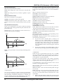
Used for instructions intended to alert
the user to the risk of death or severe
injury should the unit be used
improperly.
Used for instructions intended to alert
the user to the risk of injury or material
damage should the unit be used
improperly.
* Material damage refers
other adverse effects
respect to the home
furnishings, as well
animals or pets.
to damage or
caused with
and all its
to domestic
• Before using this unit, make sure to read the
instructions below, and the Owner's Manual.
.........................................................................................................
• Do not open or perform any internal modifications
on the unit. (The only exception would be where
this manual provides specific instructions which
should be followed in order to put in place userinstallable options; see page 45.)
.........................................................................................................
• When using the unit with a rack or stand recommended by Roland, the rack or stand must be carefully placed so it is level and sure to remain stable.
If not using a rack or stand, you still need to make
sure that any location you choose for placing the
unit provides a level surface that will properly support the unit, and keep it from wobbling.
.........................................................................................................
• Avoid damaging the power cord. Do not bend it
excessively, step on it, place heavy objects on it, etc.
A damaged cord can easily become a shock or fire
hazard. Never use a power cord after it has been
damaged.
.........................................................................................................
• In households with small children, an adult should
provide supervision until the child is capable of following all the rules essential for the safe operation
of the unit.
.........................................................................................................
• Protect the unit from strong impact.
(Do not drop it!)
.........................................................................................................
• Do not force the unit's power-supply cord to share
an outlet with an unreasonable number of other
devices. Be especially careful when using extension
cords—the total power used by all devices you
have connected to the extension cord's outlet must
never exceed the power rating (watts/amperes) for
the extension cord. Excessive loads can cause the
insulation on the cord to heat up and eventually
melt through.
.........................................................................................................
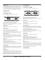
The
symbol alerts the user to important instructions
or warnings.The specific meaning of the symbol is
determined by the design contained within the
triangle. In the case of the symbol at left, it is used for
general cautions, warnings, or alerts to danger.
The
symbol alerts the user to items that must never
be carried out (are forbidden). The specific thing that
must not be done is indicated by the design contained
within the circle. In the case of the symbol at left, it
means that the unit must never be disassembled.
The ● symbol alerts the user to things that must be
carried out. The specific thing that must be done is
indicated by the design contained within the circle. In
the case of the symbol at left, it means that the powercord plug must be unplugged from the outlet.
• Before using the unit in a foreign country, consult
with your retailer, the nearest Roland Service
Center, or an authorized Roland distributor, as listed on the "Information" page.
.........................................................................................................
• Always turn the unit off and unplug the power
cord before attempting installation of the circuit
board (SR-JV80 series; page 45).
.........................................................................................................
• Always grasp only the plug on the power-supply
cord when plugging into, or unplugging from an
outlet.
.........................................................................................................
• Try to prevent cords and cables from becoming
entangled. Also, all cords and cables should be
placed so they are out of the reach of children.
.........................................................................................................
• Never climb on top of, nor place heavy objects on
the unit.
.........................................................................................................
• Never handle the power cord or its plug with wet
hands when plugging into, or unplugging from, an
outlet.
.........................................................................................................
• Before moving the unit, disconnect the power plug
from the outlet, and pull out all cords from external
devices.
.........................................................................................................
• Before cleaning the unit, turn off the power and
unplug the power cord from the outlet (page 4).
.........................................................................................................
• Whenever you suspect the possibility of lightning
in your area, pull the plug on the power cord out of
the outlet.
.........................................................................................................
• Install only the specified circuit board(s) (SR-JV80
series). Remove only the specified screws (page 45).
.........................................................................................................
3
IMPORTANT NOTES
In addition to the items listed under “IMPORTANT
SAFETY INSTRUCTIONS” and “USING THE UNIT
SAFELY” on pages 2 and 3, please read and observe
the following:
Power Supply
• Do not use this unit on the same power circuit with
any device that will generate line noise (such as an
electric motor or variable lighting system).
• Before connecting this unit to other devices, turn off
the power to all units. This will help prevent malfunctions and/or damage to speakers or other devices.
Placement
• Using the unit near power amplifiers (or other
equipment containing large power transformers)
may induce hum. To alleviate the problem, change
the orientation of this unit; or move it farther away
from the source of interference.
• This device may interfere with radio and television
reception. Do not use this device in the vicinity of
such receivers.
• Observe the following when using the unit’s floppy
disk drive. For further details, refer to “Before Using
Floppy Disks” (page 5).
- Do not place the unit near devices that produce a
strong magnetic field (e.g., loudspeakers).
- Install the unit on a solid, level surface.
- Do not move the unit or subject it to vibration
while the drive is operating.
• Do not expose the unit to direct sunlight, place it
near devices that radiate heat, leave it inside an
enclosed vehicle, or otherwise subject it to temperature extremes. Excessive heat can deform or discolor
the unit.
Maintenance
• For everyday cleaning wipe the unit with a soft, dry
cloth or one that has been slightly dampened with
water. To remove stubborn dirt, use a cloth impregnated with a mild, non-abrasive detergent.
Afterwards, be sure to wipe the unit thoroughly
with a soft, dry cloth.
• Never use benzine, thinners, alcohol or solvents of
any kind, to avoid the possibility of discoloration
and/or deformation.
Repairs and Data
• Please be aware that all data contained in the unit’s
memory may be lost when the unit is sent for
repairs. Important data should always be backed up
on a floppy disk, or written down on paper (when
possible). During repairs, due care is taken to avoid
4
the loss of data. However, in certain cases (such as
when circuitry related to memory itself is out of
order), we regret that it may not be possible to
restore the data, and Roland assumes no liability
concerning such loss of data.
Memory Backup
• This unit contains a battery which powers the unit’s
memory circuits while the main power is off. When
this battery becomes weak, the message shown
below will appear in the display. Once you see this
message, have the battery replaced with a fresh one
as soon as possible to avoid the loss of all data in
memory. To have the battery replaced, consult with
your retailer, the nearest Roland Service Center, or
an authorized Roland distributor, as listed on the
“Information” page.
“Battery Low”
Additional Precautions
• Please be aware that the contents of memory can be
irretrievably lost as a result of a malfunction, or the
improper operation of the unit. To protect yourself
against the risk of loosing important data, we recommend that you periodically save a backup copy of
important data you have stored in the unit’s memory on a floppy disk.
• Unfortunately, it may be impossible to restore the
contents of data that was stored on a floppy disk, in
the unit’s memory or another MIDI device (e.g., a
sequencer) once it has been lost. Roland Corporation
assumes no liability concerning such loss of data.
• Use a reasonable amount of care when using the
unit’s buttons, sliders, or other controls; and when
using its jacks and connectors. Rough handling can
lead to malfunctions.
• Never strike or apply strong pressure to the display.
• When connecting / disconnecting all cables, grasp
the connector itself—never pull on the cable. This
way you will avoid causing shorts, or damage to the
cable’s internal elements.
• A small amount of heat will radiate from the unit
during normal operation.
• To avoid disturbing your neighbors, try to keep the
unit’s volume at reasonable levels. You may prefer
to use headphones, so you do not need to be concerned about those around you (especially when it is
late at night).
• When you need to transport the unit, package it in
the box (including padding) that it came in, if possible. Otherwise, you will need to use equivalent
packaging materials.
• Use only the specified expression pedal (EV-5; sold
separately). By connecting any other expression pedals, you risk causing malfunction and/or damage to
the unit.
Before Using Floppy Disks
Handling the Floppy Disk Drive
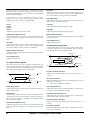
• Install the unit on a solid, level surface in an area
free from vibration. If the unit must be installed at
an angle, be sure the installation does not exceed the
permissible range: upward, 5°; downward, 35°.
• Avoid using the unit immediately after it has been
moved to a location with a level of humidity that is
greatly different than its former location. Rapid
changes in the environment can cause condensation
to form inside the drive, which will adversely affect
the operation of the drive and/or damage floppy
disks. When the unit has been moved, allow it to
become accustomed to the new environment (allow
a few hours) before operating it.
• To insert a disk, push it gently but firmly into the
drive—it will click into place. To remove a disk,
press the EJECT button firmly. Do not use excessive
force to remove a disk which is lodged in the drive.
• Never attempt to remove a floppy disk from the
drive while the drive is operating (the indicator is
brightly lit); damage could result to both the disk
and the drive.
• Remove any disk from the drive before powering up
or down.
• To prevent damage to the disk drive’s heads, always
try to hold the floppy disk in a level position (not
tilted in any direction) while inserting it into the
drive. Push it in firmly, but gently. Never use excessive force.
Handling Floppy Disks
• Floppy disks contain a plastic disk with a thin coating of magnetic storage medium. Microscopic precision is required to enable storage of large amounts
of data on such a small surface area. To preserve
their integrity, please observe the following when
handling floppy disks:
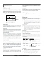
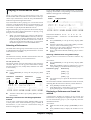
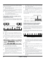
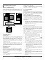
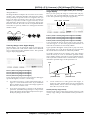
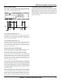
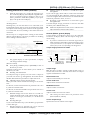
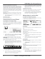
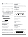
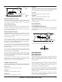
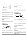
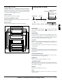
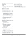
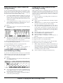
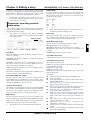
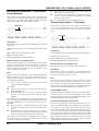
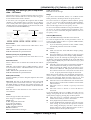
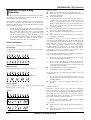
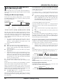
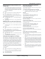
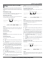
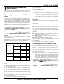
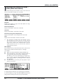
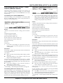
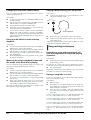
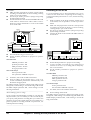
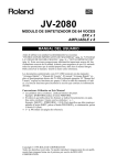
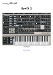
• Floppy disks have a “write protect” tab which can
protect the disk from accidental erasure. It is recommended that the tab be kept in the PROTECT position, and moved to the WRITE position only when
you wish to write new data onto the disk.
Protect tab
Write (writing permitted)
Protect (writing prohibited)
• The identification label should be firmly affixed to
the disk. Should the label come loose while the disk
is in the drive, it may be difficult to remove the disk.
• Put the disk back into its case for storage.
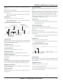
Handling and Installing the Wave Expansion Board
(SR-JV80 series)
• To avoid the risk of damage to internal components
that can be caused by static electricity, please carefully observe the following whenever you handle
the board.
- Before you touch the board, always first grasp a
metal object (such as a water pipe), so you are sure
that any static electricity you might have been carrying has been discharged.
- When handling the board, grasp it only by its
edges. Avoid touching any of the electronic components or connectors.
• Do not touch any of the printed circuit pathways or
connection terminals.
• Never use excessive force when installing a circuit
board. If it doesn’t fit properly on the first attempt,
remove the board and try again.
• When circuit board installation is complete, doublecheck your work.
- Never touch the magnetic medium inside the disk.
- Do not use or store floppy disks in dirty or dusty
areas.
- Do not subject floppy disks to temperature
extremes (e.g., direct sunlight in an enclosed vehicle). Recommended temperature range: 10 to 50° C
(50 to 122° F).
- Do not expose floppy disks to strong magnetic
fields, such as those generated by loudspeakers.
5
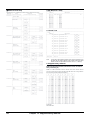
Features of the XP-60/XP-80
Expandability
GM System compatibility
Allows four Wave Expansion Boards to be installed at
the same time.
The XP-60/XP-80 provides a mode compatible with the GM
System, the standard format for desktop music (DTM) systems, and can play back commercially available GM compatible song data. (p.173)
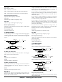
The XP-60/XP-80 can take up to four Wave Expansion
Boards at one time for complex sounds that use prodigious
amounts of waveform data. (p.45)
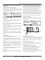
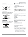
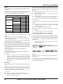
GM System
The XP-60/XP-80 will play back music data from popular,
commercial Standard MIDI File (SMF) music data releases as
well as Super-MRC format song data from sequencers. (p.97,
102)
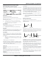
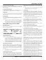
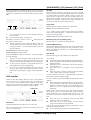
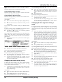
GM (General MIDI) is an industry-wide set of specifications
for sound sources, which allows music data to be created
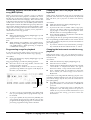
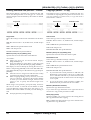
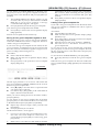
and played back regardless of manufacturer or specific models. GM compatible song data carries the GM logo (
),
indicating that it will correctly play back on any GM compatible sound source.
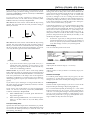
Quick and intuitive operation
Full-fledged sequencer – MRC Pro
Large display
Quick Play for immediate song playback
A large display provides at-a-glance indication of all the
related parameters. The comprehensive graphic display
enables simple editing and onscreen confirming.
A song from floppy disk can be played back directly without
having to load it into internal memory. (p.98)
Enhanced operational ease
Non-stop loop recording for smoother song creation
without interruptions
Dedicated buttons are provided for each function to simplify
operation. [F1]–[F6] buttons located below the display allow
intuitive editing. (p.20)
While recording, destination phrase tracks can be changed
so drum, bass, and melody parts can be recorded in continuous sequence. (p.109)
Multiple outputs
RPS (Realtime Phrase Sequencing) – a powerful feature
for onstage performance
Standard MIDI File compatibility
The XP-60/XP-80 is equipped with MIX OUTPUT and
DIRECT OUTPUT stereo outputs. Outputs from two independent jacks allow different instrument sounds to be
processed individually using external effects units and
sophisticated mixing. (p.60, 68)
Click output to external equipment
With RPS, your own patterns can be assigned to a key and
played back simply by pressing that key. This makes intricate phrases easier to play. (p.150)
Chain Play for continuous playback of specified songs
A set of headphones or amp can be connected to the CLICK
OUTPUT jack for audible reference click. (p.180)
Chain Play plays back songs on a disk in the sequence you
want, convenient when using the XP-60/XP-80’s sequencer
in performance. (p.153)
High-performance synthesizer sound source
Groove Quantize for creating your own groove
64-voice polyphony and 16-part multitimbrality
The XP-60/XP-80 is a 16-part multitimbral sound source that
produces up to 64 simultaneous polyphonic notes.
Effectively used with the built-in sequencer or an external
computer, the XP-60/XP-80’s true creative potential for
music production becomes apparent. (p.19)
Powerful onboard effects
Advanced DSP (Digital Signal Processor) technology provides a wide array of studio quality effects. In addition to
the multiple effects (EFX) section that features 40 different
types of effects, the XP-60/XP-80 also features an independent chorus unit and reverb unit. (p.39)
Extensive Tone structure range
Ten different Structures are available for combining basic
sound elements for more flexible sound making. A ring
modulator and booster enhance creating sounds. (p.49)
An array of arpeggio and cutting options
With the [ARPEGGIO] on, you can create various arpeggios
and simulate cutting techniques simply by pressing a chord.
You can even specify the rhythmical ‘feel’ you want. (p.35)
6
Choose your favorite from the 71 groove templates provided. Groove templates can also be customized and 16 of them
can be stored in the user area. (p.139, 142)
Preview supports Quantize functions
Preview lets you check out groove variations in real time
while setting Quantize parameters. This helps you get the
exact result you want with Shuffle Quantize and Groove
Quantize. (p.136)
Allows playback in sync with the Roland “VS-880” hard
disk recorder
You can synchronize the XP-60/XP-80 to the VS-880 and
vice versa, simply by connecting these two devices via a
MIDI cable and setting the necessary parameters. This
allows you to digitally record a song created on the XP60/XP-80 along with vocals and live performance on the VS880. (p.184)
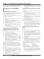
Chapter outlines
For XP-60 Owners
Even though only the XP-80 model is referred to in this manual and in the Quick Start manual, all operations are common to both the XP-80 and XP-60.
Please substitute "XP-60" for each occurrence of "XP-80" that
you find in this Owner's Manual and the Quick Start.
This manual is divided into 12 chapters. But before you start
reading it, we’d like to suggest going through the Quick
Start booklet.
Chapter 1. An overview of the XP-80
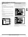
This chapter covers XP-80 sound source and sequencer section configurations, as well as basic operation. Please be sure
to read this chapter in order to fully understand the XP-80.
Chapter 2. Playing
This chapter explains how to use the XP-80 in Patch,
Performance and Rhythm Set modes. Reading it is essential
for understanding XP-80 operational procedures.
Chapter 3. Creating your own sounds
This chapter covers creating sounds, the parameters that
make up a Patch, Performance, or Rhythm Set, and the
System parameters that determine global XP-80 operation, as
well as their functions. Comprehending the information in
the chapter is an essential prerequisite before creating your
own sounds.
Chapter 4. Playing back and recording a song
This chapter is a detailed discussion on playing back and
recording a song. Understanding this chapter is essential for
correctly operating the XP-80.
Chapter 5. Editing a song
This chapter explains song editing and song settings in
detail. It’s important to know this material when you wish to
edit a pre-recorded song using the Track Edit, Microscope
Edit and/or Quantize functions.
Chapter 6. Realtime Phrase Sequencing (RPS)
This chapter covers RPS in some detail, including RPS settings and how to play back a song using the RPS function.
Chapter 7. Playing songs in sequence (Chain Play)
The function that consecutively plays back songs from disk
in an order you specify is called ‘Chain Play.’ This chapter
explains Chain Play settings and how to play songs back.
Chapter 8. XP-80 memory settings (Utility mode)
This chapter goes over the various Utility functions such as
storing Patch, Performance or Rhythm Set data, clearing the
internal memory, etc. Being familiar with these will streamline operation procedures.
Chapter 9. Disk-related functions (Disk mode)
This chapter covers disk-related operations such as saving
data to disk, loading data from disk into internal memory,
etc.
Chapter 10. Using the XP-80 as the GM sound source
This chapter explains needed procedures and parameters for
using the XP-80 as a GM System-compatible sound source.
Read this chapter before attempting to play back commercial
GM score data.
Chapter 11. Getting the full potential of the XP-80
This chapter includes various techniques that expand the
XP-80’s operational scope. It includes use with external
MIDI devices, live performance applications and others.
Chapter 12. Supplementary material
This chapter contains a troubleshooting section for use when
the XP-80 is not functioning as expected. There is also a list
of error messages that you can refer to if an error message
appears on the display. A list of parameters and MIDI implementation chart are also provided.
❚
Notation used in this Owner’s
Manual
To make operation procedures easy to understand, the following notation system is adopted:
Characters and numbers in square brackets [] indicate buttons on the front panel. For example, [PATCH] represents
the PATCH button and [ENTER] the ENTER button.
An asterisk (✳) at the beginning of a paragraph indicates a
note or precaution. These should not be ignored.
(p.??) refers to pages within the manual.
Columns marked by ••••• include supplementary information regarding functions or tips on operation.
<Procedure> section discusses operational steps that should
be read.
(Basic Procedure) section explains basic procedures covering each function. Please read these because they’ll make it
easier for you later.
(Examples) section provides examples for reference.
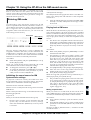
Paragraphs that explain parameters are titled “Onscreen
abbreviation indication (full name of parameter).”
Examples
RTC 1 (Realtime controller 1)
Through (Thru function switch)
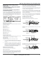
In the text, parameters are referred to as “Channel parameter
(PERFORM/MIDI/Part MIDI) for instance. This means the
Channel parameter is found in the MIDI Group’s Part MIDI
display in Performance mode. Display screens will also be
referred to in a similar manner; e.g., “Part MIDI display
(PERFORM/MIDI).”
Mode
Display group Display name
For parameters located in the same display, descriptions in
parentheses ( ) are omitted; e.g., “Rx Switch parameter.”
Display screens
Display screen figures in this manual may sometimes differ
from factory settings.
7
Contents
IMPORTANT NOTES ...................................................................................................................4
Features of the XP-60/XP-80......................................................................................................6
Chapter outlines .........................................................................................................................7
Contents ......................................................................................................................................8
Names and functions of buttons and controls ......................................................................14
Chapter 1. An overview of the XP-80 ................................................................18
XP-80 configuration..................................................................................................................18
Basic configuration .....................................................................................................................18
Classification of XP-80 sound types ...........................................................................................18
Basic operation.........................................................................................................................20
Switching modes ........................................................................................................................20
Switching displays ......................................................................................................................20
Moving the cursor .......................................................................................................................23
Modifying a value........................................................................................................................23
Assigning a name .......................................................................................................................24
Chapter 2. Playing...............................................................................................26
Playing in Patch mode .............................................................................................................26
Selecting a Patch........................................................................................................................26
Displaying a Patch list ................................................................................................................27
Making a Patch sound thick or thin (turning a Tone on/off) ........................................................27
Playing single notes (Solo) .........................................................................................................28
Creating smooth pitch changes (Portamento) ............................................................................28
Quick sound character changes (Sound Palette) .......................................................................28
Playing in Performance mode .................................................................................................29
Selecting a Performance ............................................................................................................29
Displaying a Performance’s Sound List window.........................................................................29
Playing fatter and richer sounds by combining Patches (Layer) ................................................30
Splitting the keyboard to play separate Patches in different sections (Split) ..............................30
Playing along with a song playback (XP-80 used as a multitimbral sound source)....................31
Assigning a different Patch to a Part ..........................................................................................32
Quick sound character changes (Sound Palette) .......................................................................32
Playing in Rhythm Set mode ...................................................................................................33
Selecting a Rhythm Set ..............................................................................................................33
Displaying Sound List window of a Rhythm Set .........................................................................34
Playing percussion instruments..................................................................................................34
Playing an arpeggio..................................................................................................................35
Playing an arpeggio over a preset keyboard area......................................................................36
Holding an arpeggio ...................................................................................................................36
Simulating a guitar cutting technique..........................................................................................36
Playing an arpeggio from an external MIDI device.....................................................................36
Creating an arpeggio pattern......................................................................................................36
Recording an arpeggio ...............................................................................................................37
Convenient functions for performance...................................................................................37
Transposing the keyboard in octave units (Octave Shift) ...........................................................37
Transposing the keyboard in semitone steps (Transpose).........................................................38
If ‘stuck’ notes occur or a note does not sound (Panic)..............................................................38
8
Chapter 3. Creating your own sounds ..............................................................39
Regarding effects .....................................................................................................................39
How effects units work in different modes ..................................................................................39
Turning effects on/off..................................................................................................................40
1
Sound editing procedures .......................................................................................................40
Editing a Patch ...........................................................................................................................40
Editing a Performance ................................................................................................................43
Editing a Rhythm Set..................................................................................................................44
2
Keeping edited sound .............................................................................................................45
Memory and data storage...........................................................................................................45
Storing a sound you modify into user memory ...........................................................................46
3
Functions of Patch parameters ...............................................................................................46
Settings common to the entire Patch (Common)........................................................................46
Modifying waveform and pitch (WG) ..........................................................................................51
Modifying the brightness of sound with a filter (TVF) .................................................................54
Changing the sound’s volume (TVA) .........................................................................................55
Modulating sounds-Adding Vibrato, Tremolo, etc./Using controllers to Change
how sounds are played (LFO&Ctl) .............................................................................................57
Setting effects for a Patch (Effects) ............................................................................................60
Functions of Performance parameters...................................................................................65
Settings common to the entire Performance (Common) ............................................................65
Setting the keyboard range (K.Range) .......................................................................................66
Making settings for each Part (Part) ...........................................................................................66
Making MIDI settings for a Part (MIDI) .......................................................................................67
Setting effects for a Performance (Effects).................................................................................68
Confirming MIDI information for each Part (Info) .......................................................................69
4
5
6
Functions of Rhythm Set parameters.....................................................................................70
Naming a Rhythm Set (Common) ..............................................................................................70
Modifying waveform and pitch of a Rhythm Tone (Key WG)......................................................70
Changing the tone (filter) of a Rhythm Tone (Key TVF) .............................................................71
Changing the volume of a Rhythm Tone (Key TVA) ..................................................................72
Controlling how a Rhythm Tone will sound with controllers (Key Ctl) ........................................72
Setting effects for a Rhythm Tone (Effects)................................................................................73
EFX effect types (EFX Parameter)...........................................................................................74
XP-80 operating environment setup (System parameters and their functions) .................88
Setups and keyboard settings (Setup) .......................................................................................88
Adjusting tuning (Tune) ..............................................................................................................89
MIDI settings (MIDI)....................................................................................................................90
Assigning sliders, pedals and other controllers (Control) ...........................................................92
Arpeggio settings (Arpeg)...........................................................................................................93
Confirming the XP-80’s current conditions (Info)........................................................................95
7
8
9
10
11
12
9
Chapter 4. Playing back and recording a song ................................................96
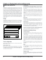
About the sequencer................................................................................................................96
Songs .........................................................................................................................................96
Track configuration .....................................................................................................................96
Position for storing a song ..........................................................................................................96
Playing back a song .................................................................................................................97
Playing back a song directly from disk (Quick Play)...................................................................98
Fast-forwarding or ‘rewinding’ a song.........................................................................................98
Resuming playback from the middle of a song (MIDI Update) ..................................................99
Programming songs for playback ...............................................................................................99
Changing the Part to be played from the keyboard ....................................................................99
Changing the instrument sounds for song playback...................................................................99
Silencing specific instruments 1 (Muting Phrase tracks) ..........................................................100
Silencing specific instruments 2 (Turning the Receive channel off) .........................................100
Playing back a song with a tempo change ...............................................................................100
Playing back a song with a constant tempo (Muting the Tempo track) ....................................101
Playing back a Pattern..............................................................................................................101
Playing back a song created in the S-MRC format ..................................................................102
Repeatedly playing back a song (Loop Play) ...........................................................................102
Changing sound character during playback .............................................................................102
Adjusting volume balance between Parts.................................................................................103
Adjusting panning of each Part.................................................................................................103
Before you start to record......................................................................................................104
Recording process....................................................................................................................104
How Phrase tracks, Parts and MIDI channels interact .............................................................104
Recording methods ..................................................................................................................104
Recording destinations of sequencer data ...............................................................................104
Selecting instrument sounds ....................................................................................................105
Erasing the song from internal memory....................................................................................105
Setting the time signature.........................................................................................................105
Recording as you play (Realtime recording)........................................................................106
Settings for realtime recording..................................................................................................106
Performing realtime recording ..................................................................................................108
Recording specific data only (Recording Select)......................................................................109
Changing the Phrase track during recording (Non-stop Loop Recording)................................109
Checking instrument sounds or phrases during recording (Rehearsal) ...................................109
Deleting unwanted data during recording (Realtime Erase).....................................................110
Recording tempo changes........................................................................................................110
Changing instrument during recording .....................................................................................110
Modifying parameter values of each Part during recording ......................................................111
Checking MIDI messages received by each Part during recording..........................................111
Changing the sound character of each Part during recording ..................................................111
Recording volume balance between Parts ...............................................................................112
Panning Parts during recording ...............................................................................................112
Canceling recording (Undo)......................................................................................................112
Inputting data step by step (Step recording) .......................................................................113
Inputting notes and rests ..........................................................................................................113
Assigning a Pattern to a Phrase track ......................................................................................114
Deleting recording (Undo) ........................................................................................................115
Saving the recorded song to disk .........................................................................................115
Saving sound data along with a song.......................................................................................115
Saving only a song ...................................................................................................................116
Saving a song in the Standard MIDI File format.......................................................................116
10
Chapter 5. Editing a song.................................................................................117
Sequencer operating environment setup.............................................................................117
Settings for an entire song ....................................................................................................118
Naming a song (Song Name) ...................................................................................................118
Naming a Pattern (Pattern Name) ............................................................................................118
Monitoring Phrase track data and settings ...............................................................................119
Locate function .........................................................................................................................119
Setting loop...............................................................................................................................120
Editing sequencer data over the specified range (Track Edit) ...........................................121
About Track Edit .......................................................................................................................121
Setting the editing area.............................................................................................................122
Erasing data input mistakes — 1 Erase ...................................................................................123
Deleting unwanted data portions — 2 Delete ...........................................................................124
Copying a phrase — 3 Copy ....................................................................................................124
Inserting blank measures — 4 Insert Meas (Insert measure)...................................................126
Transposing the pitch — 5 Transpose......................................................................................126
Modifying velocity — 6 Chg Velocity (Change velocity) ...........................................................127
Changing MIDI channel — 7 Chg Channel (Change MIDI channel) ........................................128
Changing note length — 8 Chg Gate Time (Change gate time)...............................................129
Combining two Phrase Tracks/Patterns into one — 9 Merge...................................................130
Extracting and moving a part of sequencer data — 10 Extract ................................................131
Shifting sequencer data backward or forward — 11 Shift Clock .............................................132
Thinning out sequencer data — 12 Data Thin..........................................................................133
Exchanging Phrase tracks/Patterns — 13 Exchange...............................................................134
Adjusting the song playback time — 14 Time Fit ....................................................................134
Deleting blank measures — 15 Truncate .................................................................................135
Aligning a song’s timing (Quantize) .....................................................................................136
About quantizing.......................................................................................................................136
Grid quantize ............................................................................................................................137
Shuffle quantize........................................................................................................................138
Groove quantize .......................................................................................................................139
Editing sequencer data one at a time (Microscope Edit) ....................................................144
Viewing the Microscope display ...............................................................................................144
Viewing only specific sequencer data.......................................................................................146
Modifying sequencer data recorded in a Phrase track/Pattern.................................................146
Modifying tempo change recorded on the Tempo track ...........................................................147
Modifying data recorded on the Beat track...............................................................................147
Setting the time signature of a Pattern .....................................................................................147
Inserting new sequencer data into a Phrase track/Pattern.......................................................147
Changing the tempo during a song ..........................................................................................148
Changing the time signature during a song..............................................................................148
Erasing sequencer data............................................................................................................149
Moving sequencer data ............................................................................................................149
Copying sequencer data...........................................................................................................149
Chapter 6. Realtime Phrase Sequencing (RPS) .............................................150
Getting ready to use RPS ......................................................................................................150
RPS parameters .......................................................................................................................150
Playing using RPS ..................................................................................................................151
Playing a Pattern from a external MIDI keyboard using RPS...................................................151
Recording performance using RPS ..........................................................................................151
11
Chapter 7. Playing songs in sequence (Chain Play)......................................153
Getting ready for Chain Play .................................................................................................153
Saving a chain to disk ............................................................................................................154
Chain play ...............................................................................................................................154
Chapter 8. XP-80 memory settings (Utility mode)..........................................155
About Utility mode..................................................................................................................155
Storing sound data in user memory — 1 Write ...................................................................156
Performance write ....................................................................................................................156
Patch write................................................................................................................................156
Rhythm Set write ......................................................................................................................156
Copying sound source settings — 2 Copy ..........................................................................157
Performance copy ....................................................................................................................157
Patch copy................................................................................................................................158
Rhythm Set copy ......................................................................................................................159
Initializing sound source settings — 3 Initialize ..................................................................160
Performance initialize ...............................................................................................................160
Patch initialize...........................................................................................................................160
Rhythm Set initialize .................................................................................................................160
Transmitting sound settings — 4 Data Transfer ..................................................................161
Transmitting data to an external MIDI device ...........................................................................161
Transmitting data to the internal song ......................................................................................161
Transmitting data to user memory............................................................................................162
Preventing user memory writing operation — 5 Protect (User memory protect).............164
Erasing the internal song — 6 Song Init (Song initialize) ..................................................164
Checking internal memory consumption — 7 Memory Info (Internal memory information) .......164
Recalling factory default settings — 8 Factory (Factory preset) .......................................165
Chapter 9. Disk-related functions (Disk mode) ..............................................166
About Disk mode ....................................................................................................................166
Loading a file from disk into the XP-80 — 1 Load ...............................................................167
Saving data to disk — 2 Save ................................................................................................168
Formatting the disk for the XP-60/XP-80 — 3 Format .........................................................169
Making a copy of a disk — 4 Backup....................................................................................170
Checking files recorded on disk — 5 Verify .........................................................................170
Changing the name of disk — 6 Volume (Change volume label) .......................................170
Deleting unwanted files — 7 Delete (Delete file)..................................................................171
Renaming a file — 8 Rename ................................................................................................171
Checking the contents of disk — 9 Info (Disk information)................................................172
Chapter 10. Using the XP-80 as the GM sound source .................................173
Entering GM mode..................................................................................................................173
Initializing the sound source for GM System basic settings .....................................................173
Playing back a GM score..........................................................................................................173
Modifying GM mode settings ................................................................................................174
Setting a Part (Part)..................................................................................................................174
Making effects settings in GM mode (Effects) ..........................................................................174
Confirming MIDI information of each Part (Info) .......................................................................175
12
Convenient functions in GM mode (GM Utility) ...................................................................176
Copying effects settings — 2 Copy (GM Copy)........................................................................176
Initializing GM mode — 3 Initialize (GM Initialize) ....................................................................176
Transmitting GM mode settings — 4 Data Transfer (GM Data Transfer).................................177
Chapter 11. Getting the full potential of the XP-80 ........................................178
Techniques for using Patches ...............................................................................................178
Reinforcing filter characteristics................................................................................................178
Making the up-beat note sound at the same time you play a down-beat note ........................178
Holding a note with modulation retained ..................................................................................178
Syncing the LFO cycle to sequencer tempo.............................................................................178
Modifying EFX to match the tempo of a song...........................................................................178
Using a pedal switch to modify the rotary speed of the Rotary effect ......................................179
Playing phrase loops at a song’s tempo...................................................................................179
Using the C1 slider to pan sounds in real time .........................................................................179
Using the XP-80 to play live...................................................................................................179
Changing multiple sounds of an external MIDI device simultaneously.....................................179
Changing sounds with a pedal switch ......................................................................................180
Using a pedal switch to start and stop playback ......................................................................180
Matching the song’s playback tempo with the tempo of the band that’s playing ......................180
Playing a drum referring to a XP-80 click .................................................................................180
Song making techniques .......................................................................................................180
Recording a song with a consistent volume level regardless of keyboard playing dynamics........180
Having a song fade in or out.....................................................................................................180
Changing a sound during a song..............................................................................................181
Avoiding sound dropouts in a song ..........................................................................................182
Using external MIDI devices ..................................................................................................182
Using the XP-80 to change the sound on an external MIDI device ..........................................182
Using the XP-80 to control external MIDI devices ....................................................................182
Playing the XP-80 sound source from an external MIDI device ...............................................183
Synchronization with external MIDI devices ........................................................................183
Syncing an external sequencer to the XP-80’s sequencer.......................................................183
Syncing the XP-80’s sequencer to an external sequencer.......................................................183
Recording a song from an external sequencer into the XP-80’s sequencer ............................183
Synchronizing to the VS-880 Hard Disk Recorder...............................................................184
Getting ready to sync to the VS-880.........................................................................................184
Playing back Song files ..........................................................................................................185
Recording on the VS-880 .........................................................................................................185
Recording on the XP-80 ..........................................................................................................186
Chapter 12. Supplementary material...............................................................187
Troubleshooting......................................................................................................................187
Error messages ......................................................................................................................188
Parameter list ..........................................................................................................................190
Factory preset settings ..........................................................................................................206
Arpeggio style list ..................................................................................................................213
MIDI implementation ..............................................................................................................214
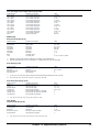
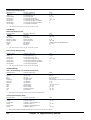
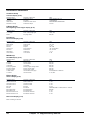
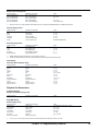
Specifications....................................................................................................231
Quick reference of displays .............................................................................232
Index...................................................................................................................241
13
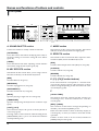
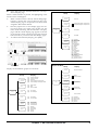
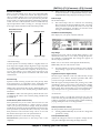
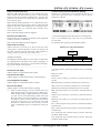
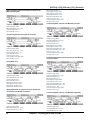
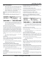
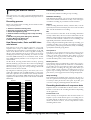
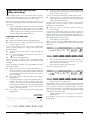
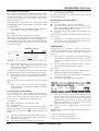
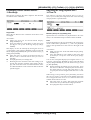
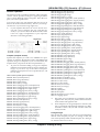
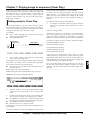
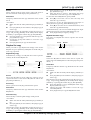
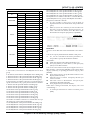
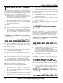
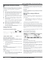
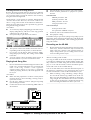
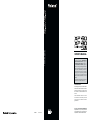
Names and functions of buttons and controls
❚
Front panel
K
A
B
CUTOFF
l
FILTER/ENV
1
LEVEL
RESO.
2
C
KEY EFFECTS
SOUND P
PALE
ALETTE
TE
FILTER l/ ENV
ATTACK
3
DECAY
4
PERFORM
PATCH
GM
PART
RPS
ARPEGGIO
SEQUENCER
PORTAMENTO
SOLO
SYSTEM
LOCAL / TX / RX
CHAIN PLAY
SOUND LIST
a/b/c/d
PATTERN
2
2
-
OCT
+
OCT
EFX
CHORUS
F2
F3
F
F4
F5
F6
EXIT
PANIC
DISK
BANK
TRACK/PART
TEMPO/BEAT
1
1
REVERB
NUMBER
TRACK/PART
1
9
EFFECTS
TRANSPOSE
F1
RHYTHM
DEMO
UTILITY
E
F
MODE
LEVEL
LOCATE
UNDO/REDO
l
3
3
4
4
5
5
6
6
7
7
8
8
TONE SWITCH
2
3
10
11
4
12
5
13
TONE SELECT
6
7
14
15
8
16
G
D
A. SOUND PALETTE section
C. MODE section
Use the four sliders to modify sounds in real time.
The buttons in this section select modes. The button
indicator of the selected mode will light (p.20).
[FILTER/ENV]
Press this button ON when modifying filter and/or
envelope settings in real time using the four sliders
(p.28, 32).
D. EFFECTS section
The buttons in this section turn their respective internal effects (EFX, Chorus and Reverb) on/off.
[LEVEL]
Press this button ON when adjusting volume balance
in real time using the four sliders (p.28, 32).
[EFX]
Switches the multiple effects unit (EFX) on/off (p.40).
B. KEY EFFECTS section
[CHORUS]
Switches Chorus on/off (p.40).
The buttons in this section allow you to assign various
functions to the keys of the XP-80’s keyboard.
[REVERB]
Switches Reverb on/off (p.40).
[RPS]
Switches RPS on/off (p.151).
E. [F1]–[F6] (Function buttons)
[ARPEGGIO]
Switches Arpeggiator on/off (p.35).
Each of these buttons corresponds to a function indicated at the display bottom. The functions of these
buttons change depending on the selected mode or the
current display (p.20).
[PORTAMENTO]
Switches Portamento on/off (p.28).
[SOLO]
Specifies playing a single note at a time (p.28).
[TRANSPOSE]
Specifies transposing the keyboard in semitone steps
(p.38).
[+OCT], [-OCT]
These buttons adjust the pitch of the keyboard in
octave steps (p.37).
Pressing either of these buttons while holding down
[TRANSPOSE] allows you to set the desired amount
of transposition (p.38).
14
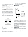
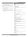
F.
[LOCAL/TX/RX]
This button opens the LOCAL/TX/RX window for
switching Local, Transmit and Receive switches
on/off (p.30).
[EXIT] / [PANIC]
The function of this button changes depending on
whether you hold down [SHIFT] or not.
EXIT: Press this button to return to the Play display of
a mode (p.21), or when you want to cancel the current
operation.
PANIC: If notes stick or do not sound, hold down
[SHIFT] and press this (p.38).
Patch/Performance/Rhythm Set with the Bank
/Number method. Use BANK [1]–[8] buttons to select
a bank and NUMBER [1]–[8] buttons to select a number (p.26, 29, 33).
Performance edit display: Use TRACK/PART [1]–[16]
buttons to select the Part to be modified (p.43).
L
VALUE
H
DEC
J
INC
7
STU
4
JKL
8
VWX
5
MNO
9
Y Z!
6
PQ R
3
E
SEQUENCER
REC
BEAT
LOOP
BWD
STOP/PLAY
l
FWD
1
F
ABC
B
I
2
3
DEF
3
GHI
D
C
SHIFT
G
0
SPACE
A
+l -
3
ENTER
DIGIT HOLD
I
[SOUND LIST] / [TEMPO/BEAT]
The function of this button changes depending on the
selected mode.
SOUND LIST: Opens the Sound List window when a
sound source mode display is up (p.27, 29, 34).
TEMPO/BEAT: Press this button for selecting a tempo
track or beat track when a Sequencer mode display is
up. If you have temporarily modified the tempo and
wish to play back the song with its initial tempo, press
it while holding down [SHIFT] (p.100).
[a/b/c/d] / [PATTERN]
The function of this button changes depending on the
mode on display.
a/b/c/d: Select a subgroup (a/b/c/d) when selecting
a Patch/Performance/Rhythm Set using the
Bank/Number method (p.26, 29, 33).
PATTERN: Select a Pattern when a Sequencer mode
display is up.
[LOCATE]
This button opens the Locate window to specify and
move the locate position (p.119).
[UNDO/REDO]
Press this button to restore a modified value to its previous (pre-modified) state, or when cancelling recording or a currently executing operation. Pressing this
button again will restart the recording/operation
(p.24).
G.
BANK [1]–[8], NUMBER [1]–[8] / TRACK / PART
[1]–[16]
The functions of these buttons change depending on
the display which is showing.
Patch edit display: TRACK/PART [1]–[4] buttons
(TONE SWITCH) are used to switch a Tone on/off
(p.27). Use TRACK/PART [5]–[8] buttons (TONE
SELECT) to select the Tone to be modified (p.40).
Rhythm Set edit display: Use TRACK/PART [5]–[8]
buttons (TONE SELECT) to select the note of the keyboard to be modified (p.44).
Sequencer mode: Use TRACK/PART [1]–[16] buttons
to select a phrase track or Part (p.108). During song
playback/recording, these buttons can be used to
switch between the Play and Mute of a phrase track
(p.100).
H.
[l], [r], [u], [d] (Cursor buttons)
Move the cursor (black box) with these (p.23).
[INC], [DEC]
Use these buttons to modify values. If you keep on
holding down one button and pressing the other, the
value change accelerates. If you press one of these buttons while holding down [SHIFT], the value will
change in bigger increments (p.23).
I. SEQUENCER section
The buttons in this section are used for playback and
recording of the XP-80’s sequencer.
[REC]
Press this to begin recording (p.106, 113).
BEAT indicator
This blinks in sync with the tempo and beat of the
song.
[LOOP]
Press this to turn Loop Play and Loop Recording
on/off (p.102).
[BWD]
Press this to “rewind” a song. Pressing this button
while holding down [SHIFT] moves you right back to
the beginning of the song. If you hold down this button as you press [FWD], the song will “rewind” faster
(p.98).
[STOP/PLAY]
Press this button to start or stop playback of the song.
Play display of a sound source mode: Selects a
15
[FWD]
Use this button to fast-forward the song. Pressing this
button while holding down [SHIFT] moves you to the
end of the song. If you hold down this button as you
press [BWD], the song will fast-forward faster (p.98).
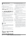
❚
Side panel
J.
[0]–[9] (Numeric keys)
Use these to set a value. They can be used to enter
numeric values as well as alphabetical characters and
notes (p.23).
[SHIFT]
This is used in combination with other buttons. Some
buttons on the front panel include grey-printed characters. They indicate the button’s function when
[SHIFT] is held down.
VOLUME
C1
C2
[ENTER] / [DIGIT HOLD]
The function of this button changes depending on
whether [SHIFT] is being held down or not.
ENTER: Use this button to finalize a value (p.23).
DIGIT HOLD: Press this button while holding down
[SHIFT] to turn the Digit Hold function on/off. With
the Digit Hold on, the 100’s place and 10’s place will
be fixed and only the 1’s place will change. This means
that you can select Patches simply by pressing the
numeric key for the 1’s place, without having to press
[ENTER] (p.27).
K.
Display
Shows various information for the currently selected
function or operation.
L.
VALUE dial
This dial is used to modify values. If you hold down
[SHIFT] as you turn the VALUE dial, the value will
change in greater increments (p.23).
16
VOLUME slider
This slider adjusts the overall output level from the
rear panel OUTPUT and PHONES jacks.
C1 slider, C2 slider
Various parameters or functions can be assigned to
these sliders, so you can control the sound source section as you play (p.92).
Pitch bend / modulation lever
This allows you to control pitch bend or apply vibrato.
Depending on the settings, other specified parameters
can also be controlled.
Floppy disk drive
3.5" 2DD/2HD floppy disks can be used. Press the
eject switch located at the lower right of the disk drive
to remove a disk.
❚
OUTPUT MIX R jack, OUTPUT MIX L jack
These jacks output the audio signal to the connected
mixer/amplifier system in stereo. For mono output,
use the L jack.
Rear panel
POWER
PHONES jack
An optional set of headphones can be connected to
this jack. Make sure that your headphones have an
impedance of 8–150 ohms.
AC
Power switch
Press to turn the power on/off.
AC inlet
Connect the AC power cable (included) to this inlet.
✳ With units rated for 117V operation, the AC cable is
already connected to the unit.
4
CONTROL PEDAL
3
2
HOLD
1
MIDI
OUT
THRU
IN
CONTROL PEDAL 1–4 jacks
You can connect the expression pedals (EV-5; sold separately) to these jacks. By assigning a desired function
to a pedal, you can use it to select or modify sound or
perform various other control. You can also connect
optional pedal switches to sustain sound (p.92).
HOLD jack
An optional pedal switch can be connected to this jack
for use as a hold pedal.
MIDI connectors
These connectors can be connected to other MIDI
devices to receive and transmit MIDI messages.
OUTPUT
CLICK OUT
LEVEL
OUTPUT
MIX
DIRECT
R
L
R
L
PHONES
CLICK OUT LEVEL knob
Adjusts the level of the click sound to be output to
external devices (p.180).
CLICK OUT OUTPUT jack
Connect a cable to this jack when sending clicks to
external devices (p.180).
OUTPUT DIRECT R jack, OUTPUT DIRECT L jack
These jacks output only the direct sound (no effects
applied) or EFX’d sound in stereo.
17
Chapter 1. An overview of the XP-80
❚
Classification of XP-80 sound types
XP-80 configuration
XP-80 sounds are made up of the following types:
Basic configuration
Tones
The XP-80 consists of a sound source, a sequencer and controllers.
Playback
Sound source
section
In the XP-80, the Tone is the smallest class of sound. Each
Tone consists of one sound. But when you play the XP-80
you will mostly play a Patch, which is made up of several
Tones. Tones therefore are the elements which collectively
form a Patch.
Tone configuration:
Sequencer
section
Tone
Play
LFO 1
LFO 2
Recording
Controller section (controllers such as
keyboard, pitch bend lever, etc.)
Sound source
The XP-80 sound source produces sound by responding to
commands in the form of MIDI messages received from its
controllers and sequencer. It will also produce sound by
responding to commands received from various external
devices it can be connected to.
Sequencer
WG
TVF
TVA
Pitch
Envelope
TVF
Envelope
TVA
Envelope
audio signal
control signal
WG (Wave Generator)
Using the Wave Generator, you select a waveform and set its
pitch.
The sequencer records various controller operations as MIDI
messages and transmits them to the sound source. MIDI
messages recorded on the sequencer can also be transmitted
from the MIDI OUT connector to allow the XP-80 to also
control external MIDI devices.
With the Time Variant Filter, you modify the waveform’s
frequency characteristics.
Controllers
TVA (Time Variant Amplifier)
Controllers include the keyboard, front panel sliders and
pedals which are connected to their respective rear panel
jacks. Adjusting these controllers enable you to produce or
modify sound.
With the Time Variant Amplifier, you set volume level and
set the sound’s position in a stereo soundfield.
TVF (Time Variant Filter)
Envelope
You use Envelope to initiate changes to occur to a sound
over time. There are separate Envelopes for the WG (pitch),
TVF (filter) and TVA (volume). For example, to modify a
sound’s attack and decay time, you would use TVA
Envelope to adjust volume changes to the sound over time.
LFO (Low Frequency Oscillator)
Use the LFO to create cyclic changes (modulation) in a
sound. The XP-80 has two LFOs. Either one or both can be
applied to effect the WG (pitch), TVF (filter) and/or TVA
(volume). To illustrate this control’s action, you can apply an
LFO to modify the WG (pitch) to create vibrato. If the LFO is
used to modify the TVA (volume), you’ll get tremolo.
18
Chapter 1. An overview of the XP-80
Patches
Rhythm Sets
Patches are the basic sound configurations that you play
during a performance. Each Patch can be configured by combining up to four Tones. How the four Tones are combined
is determined on the Structure display (Patch/Common).
A Rhythm Set is a grouping of percussion instruments
(Rhythm Tones). Since percussion instruments generally do
not play melodies, there is no need for a percussion instrument sound to be able to play a scale on the keyboard. It is
however, more important that as many as possible percussion instruments be available to you at the same time.
Therefore, each key (Note number) of a Rhythm Set will produce a different percussion instrument.
Patch
Tone 4
Tone 3
Tone 2
Tone 1
Rhythm Set
Note Number 98 (D7)
LFO 1
LFO 2
Note Number 97 (C#7)
Note Number 36 (C2)
Note Number 35 (B1)
Rhythm Tone (Percussion instrument sound)
WG
TVF
TVA
Pitch
Envelope
TVF
Envelope
TVA
Envelope
WG
TVF
TVA
Pitch
Envelope
TVF
Envelope
TVA
Envelope
Parts
Performances
The next level in sound configuration. A single Performance
groups 15 Patches and one Rhythm Set so that they can be
combined to play ensembles or produce fabulously rich,
thick sounds. One Performance allows a single XP-80 to control up to 16 instrument sounds. Because the XP-80 sound
source can control multiple sounds (instruments) it is called
a ‘multitimbral sound source.’
Performance
When the XP-80 is used as a multitimbral sound source,
another sound configuration called a Part comes into play. A
Part contains a Patch or Rhythm Set. For multimbral applications, the Performance consists of 16 Parts. A specific Patch
can be assigned to each Part except Part 10 because Part 10 is
universally set as the Drum Part to which a Rhythm Set (discussed above) is assigned. In a multimbral context, it helps
to think of a Performance as an orchestra, each Part in it
being a musician, and the Patch or Rhythm Set that musician’s instrument.
For details regarding following items, please
refer to each corresponding page.
Part 16 (MIDI receive ch.)
About the Memory (p. 45)
About the Effects (p. 39)
About the Sequencer (p. 96)
About the Song (p. 97)
Part 11 (MIDI receive ch.)
Patch
Part 10 (MIDI receive ch.)
Sequencer,
Keyboard,
MIDI
Rhythm Set
Part 9 (MIDI receive ch.)
Sound
Part 1 (MIDI receive ch.)
Patch
Chapter 1. An overview of the XP-80
19
1
❚
To set GM mode, hold down [SHIFT] and press [PERFORM]. [PERFORM], [PATCH] and [RHYTHM] indicators
will not light.
Basic operation
Switching modes
Sequencer
The XP-80 has enough functions to bewilder you. To make it
easy to access the functions you need for specific applications, they’re grouped into modes. The mode you’ve selected determines how the sound source operates and what the
display shows. Select a Mode button. It will light and the
Play display of that selected mode will appear.
Selecting Sequencer mode and Chain Play mode determines
how the sequencer will operate. One or the other of these
modes has to be selected for the sequencer to operate.
Sequencer mode
For recording, playing back and editing a song.
Chain Play mode
MODE
PERFORM
PATCH
GM
PART
This allows you to select the order of how you want songs to
play back.
RHYTHM
Sound source
SEQUENCER
CHAIN PLAY
Sequencer
SYSTEM
UTILITY
System mode
This mode is for determining global XP-80 settings such as
tuning, display contrast and how MIDI messages are
received.
✳
DISK
Sound source
Selecting Patch mode, Performance mode, Rhythm Set
mode, and GM mode will determine sound source operation. One mode always has to be selected.
Some System mode parameters relate to an entire
Patch or an entire Performance. To set these parameters, press [SYSTEM] in the selected mode (Patch or
Performance).
Utility mode
The mode for saving and transmitting sound source settings.
✳
Patch mode
Some Utility mode parameters relate to an entire
Patch, Performance or Rhythm Set. To set these parameters, press [UTILITY] in the selected mode (Patch,
Performance or Rhythm Set).
In this mode, you can play an individual Patch from the keyboard or modify Patch settings. If you’re using an external
MIDI device to control the XP-80 in this mode, it will function as a single-patch sound source.
Disk mode
Performance mode
Switching displays
This mode makes the XP-80 function as a multitimbral
sound source, and Performance settings can be modified. If
you’re using an external MIDI device to control the XP-80 in
this mode, it will function as a multitimbral sound source.
To modify the settings of a Patch that’s assigned to a Part,
hold down [PERFORM] and press [PATCH]. Both button
indicators will light.
For saving/loading data to/from the internal Floppy Disk.
Displays are grouped by mode. The bottom line displays
functions corresponding to [F1]–[F6] (function buttons).
Press the corresponding function button to call up the
desired display.
Mode
Display group
Display name
Rhythm Set mode
This is how you can play a Rhythm Set from the keyboard
and modify the Rhythm Set settings. In this mode, the keyboard will play the Rhythm Set, but the XP-80 continues to
function as a multitimbral sound source. So your effects settings of the currently selected Performance will be heard as
you play the Rhythm Set. Rhythm Sets are assigned to Part
10 of the Performance. If you’re using an external MIDI
device to control the XP-80 in this mode, it will still function
as a multitimbral sound source.
F1
F3
F4
F5
F6
Function Name
<Procedure>
GM mode
This special mode makes the XP-80 function as a GM compatible sound source. You should select this mode when you
want to play back a GM score (music data created for GM
sound source).
❶
On the Play display of a selected mode (Menu display
will appear for Disk mode and Utility mode), press a
function button to choose a display group.
One of the selected group’s display pages will appear.
✳
20
F2
The number of display pages varies by group.
Chapter 1. An overview of the XP-80
❷
Press the respective function button to call up a
desired display page.
When a function button is pressed, the highlighting of the
function name will disappear.
✳
✳
✳
Performance Mode
Group
F1
When a function name is boxed, without being highlighted, it means that special functions like GoTo
another display page or an operation execute has been
assigned to that function button.
Data may require two or more display pages if it cannot all be shown on a single page. In that case, the
index mark indicating the total number of display
pages and the current display page appears to the left
of the function name. Repeat-pressing the function
button will allow you move to the other display pages.
Display
Common
Common
K.Range
Part Key Range Upper: Lower (Part 1-8)
Part Key Range Upper: Lower (Part 9-16)
F2
F3
Play
Part
Part Param
MIDI
Part MIDI
F4
To return to the home Play display, press [EXIT].
F5
Effects
F6
Info
F2
[F1]
[F2]
[F3]
[F4]
[F5]
--Part
[F1]
[F2]
[F3]
[F4]
[F5]
--Part
[F1]
[F2]
[F3]
[F4]
[F5]
--Part
[F1]
[F2]
General
EFX Param
EFX Control
Chorus
Reverb
Information-Modulation
Breath
Foot
Volume
Pan
Information-Expression
Hold-1
Pitch Bend
Channel Aftertouch
Voices
Information-System Control 1
System Control 2
Rhythm Set Mode
Index mark
Group
Displays are divided into groups for each mode:
Display
F1
Patch Mode
Common
Rhythm Set Name
Key WG
Wave
Pitch Envelope
Key TVF
TVF Param
TVF Envelope
Key TVA
TVA Param
TVA Envelope
Key Ctl
Control Param
F2
Group
F1
Common
F2
WG
F3
Play
TVF
F4
TVA
Display
[F1]
[F2]
[F3]
[F4]
[F5]
Common General
Common Control
Structure
Tone Key Range Lower:Upper
Tone Vel Range Lower:Upper: Fade
[F1]
[F2]
[F3]
Wave Param
Pitch
Pitch Envelope
[F1]
[F2]
TVF Param
TVF Envelope
[F1]
[F2]
TVA Param
TVA Envelope
F3
Play
F4
F5
F6
Effects
LFO&Ctl
[F1]
[F2]
[F3]
[F4]
LFO 1 Param
LFO 2 Param
Control Param
Control Switch
Effects
[F1]
[F2]
[F3]
[F4]
[F5]
General
EFX Param
EFX Control
Chorus
Reverb
F5
F6
Chapter 1. An overview of the XP-80
[F1]
[F2]
[F3]
[F4]
[F5]
General
EFX Param
EFX Control
Chorus
Reverb
21
GM Mode
Chain Play Mode
Group
Display
Group
F5
F4
Save
Part Param
Part
Display
Save
Play
F5
Effects
Play
F6
Info
[F1]
[F2]
[F3]
[F4]
[F5]
--Part
[F1]
[F2]
[F3]
[F4]
[F5]
--Part
[F1]
[F2]
[F3]
[F4]
[F5]
General
EFX Param
EFX Control
Chorus
Reverb
Information-Modulation
Breath
Foot
Volume
Pan
Information-Expression
Hold-1
Pitch Bend
Channel Aftertouch
Voices
F6
List
Chain File List Window
System Mode
Group
Display
F1
Setup
Setup
Tune
Tune
MIDI
MIDI Param 1
MIDI Param 2
Bank Select Group
F2
UTILITY
UTILITY
Utility Menu
-----Menu 1----[F2] Copy
[F3] Initialize
[F4] Data Transfer
-----Menu 2----[F6] Song Initialize
[F7] Memory Info
-----Menu 3----[F8] Factory
F3
F4
Control
Sequencer Mode
F5
Group
F1
Setup
F2
Quantiz
F3
Play
Trk Edit
(Song/Pattern)
F4
Micro
Arpeg
Display
[F1]
[F2]
[F3]
[F4]
[F6]
Song Name
Pattern Name
Track Information
RPS Setup
SEQ System Setup
[F1]
[F2]
[F3]
Grid Quantize
Shuffle Quantize
Groove Quantize
-----Menu 1----[F1] Erase
[F2] Delete
[F3] Copy
[F4] Insert Meas
[F5] Transpose
-----Menu 2----[F1] Change Velocity
[F2] Change Channel
[F3] Change Gate Time
[F4] Merge
[F5] Extract
-----Menu 3----[F1] Shift Clock
[F2] Data Thin
[F3] Exchange
[F4] Time Fit
[F5] Truncate
[F1] Create Event
[F3] Move Event
[F6] View Select
[REC] Step Recording
Loop
Info
Display
DISK
DISK
Display
UTILITY
REC
REC
Song List Window
Disk Menu
-----Menu 1----[F1] Load
[F2] Save
[F3] Format
[F4] Backup
[F5] Verify
-----Menu 2----[F1] Volume
[F2] Delete
[F3] Rename
-----Menu 3----[F1] Disk Information
Utility Mode
UTILITY
List
System Information
Disk Mode
Loop Window
F6
Arpeggio
F6
F5
22
Control Assign
Pedal Assign
Control Source
Utility Menu
-----Menu 1----[F1] Write (Patch/Perform/Rhythm)
[F2] Copy (Patch/Perform/Rhythm)
[F3] Initialize (Patch/Perform/Rhythm)
[F4] Data Transfer (to MIDI/to Seq/to User)
[F5] User Memory Protect
-----Menu 2----[F1] Song Initialize
[F2] Internal Memory Information
-----Menu 3----[F1] Factory Preset
[F1] Part Palette
[F2] Part Information
[F3] Rec Filter Window
[F4] Auto Punch I/O Window
[F5] Loop Window
[F6] Rec Quantize Window
[STOP /PLAY] Recording Realtime
Rec Stand-by
Chapter 1. An overview of the XP-80
...........................................................................................................
✳
<Windows>
To assist you, a small window box may appear. It can indicate a list, confirm operation, or help input procedure
depending on the situation.
If the value of the parameter has not been finalized, the
value on which cursor is positioned is only boxed
without highlighting. Press [ENTER] to finalize the
value and return to the normal display.
Modifying a value
To modify a value, use the VALUE dial, [INC]/[DEC] or
[0]–[9] (numeric keys).
Window
Windows can be opened with their respective buttons and
closed by pressing [EXIT] or the button you used to open it.
Some windows will close automatically after a pertinent
operation is executed.
Numeric Key
DEC
INC
7
STU 8
4
JKL 5
VWX 9
Y Z!
MNO 6
PQ R
3
...........................................................................................................
Moving the cursor
SEQUENCER
Generally a single display page indicates two or more items
(parameters). Move the cursor (black box with value highlighted) to the parameter whose value you want to set or
modify. Move the cursor with the [u], [d], [l] and [r] (cursor buttons).
BEAT
LOOP
BWD
STOP l/ PLAY
FWD
E
F
1
ABC 2
B
I
✳
DEC
REC
INC
3
0
A
GHI
D
C
SHIFT
G
DEF 3
SPACE
3
ENTER
+ l - DIGIT HOLD
Each parameter has a specific range, so you cannot set
any value smaller than the minimum value or greater
than the maximum value.
VALUE dial
SEQUENCER
REC
BEAT
LOOP
BWD
STOP l/ PLAY
FWD
Turning the VALUE dial clockwise increases the value,
counterclockwise decreases the value. Holding down
[SHIFT] as you move the VALUE dial increases value increments so you can make large value changes faster.
[INC] and [DEC]
I
[u]: moves the cursor up.
Pressing this button when the cursor is at the upper left
parameter (home position) shifts it to the lower right parameter.
[d]: moves the cursor down.
Pressing this button when the cursor is at the lower right
parameter shifts it to the upper left parameter (home position).
[l]: moves the cursor to the left.
Holding down [SHIFT] while you press this button shifts the
cursor back to home.
Pressing [INC] increases the value, and [DEC] decreases it.
Keep [INC] or [DEC] pressed for continuous adjustment. For
faster value increases, keep [INC] pressed down and press
[DEC]. For decreasing value faster, keep [DEC] pressed
down and press [INC].
If you press [INC] or [DEC] while holding down [SHIFT],
the value increments will get bigger.
[0]–[9] (Numeric Keys)
[0]–[9] are called ‘numeric keys’ and are for directly specifying numerical values. When you enter a number using the
numeric keys, the cursor will change from a black box to a
white box, and the highlight of the value will be removed.
Now finalize the value by pressing [ENTER].
To go from a positive to negative value (+/-), or vice versa,
hold down [SHIFT] and press [0].
✳
Some parameters do not require you to [ENTER] them.
[r]: moves the cursor to the right.
Chapter 1. An overview of the XP-80
23
(Example)
Note value
<To enter a value of 38>
Use numeric keys to specify a note value in step recording,
etc. The corresponding note value is at the lower right of
each numeric key.
Press [3] → press [8] → press [ENTER].
<To enter a value of -60>
While holding down [SHIFT] press [0] → press [6] → press
[ENTER].
✳
3
You can switch from a positive to negative numerical
value anytime before you press [ENTER].
3
Special functions of the numeric keys
You can use the numeric keys to specify non-numerical settings for some parameters.
3
Performance/Patch/Rhythm Set group
On the Play displays for Performance, Patch or Rhythm Set
mode, you can hold down [SHIFT] and press numeric keys
to specify groups.
Buttons
Group
SHIFT+0
USER
SHIFT+1
PR-A (Preset A)
SHIFT+2
PR-B (Preset B)
SHIFT+3
PR-C (Preset C)
SHIFT+4
GM (General MIDI)
SHIFT+5
XP-A (Wave Expansion Board installed in EXP-A Slot)
SHIFT+6
XP-B (Wave Expansion Board installed in EXP-B Slot)
SHIFT+7
XP-C (Wave Expansion Board installed in EXP-C Slot)
SHIFT+8
XP-D (Wave Expansion Board installed in EXP-D Slot)
✳
Characters
When assigning a name for Patches, Performances, files and
songs, you can use the numeric keys to specify alphabetic
characters.
✳
For details, refer to “Assigning a name” below.
Restoring a previous value (Undo)
If you wish to restore a value to its immediate previous
value, press [UNDO/REDO] to return the value to its premodified state.
The Undo function can be used when modifying sound
source settings, recording a song, editing a song, etc.
✳
This procedure also applies when editing
Performances, Patches or Rhythm Sets, and for Utility
mode.
If you are in the middle of an operation that requires
rewriting large amounts of data (such as song editing),
a message window will show “Memory is low!! So you
cannot undo. Execute anyway?” If you are sure you
won’t have to undo the current operation, press [F5]
(OK). Pressing [F6] (Cancel) cancels the operation.
Assigning a name
Note name
To enter a note name in Track editing mode or Microscope
editing mode, hold down [SHIFT] and press the appropriate
numeric key. The corresponding note name is at the lower
left of each numeric key.
The XP-80 allows you to assign a name to data types such as:
Patch, Performance, Rhythm Set, Song, Pattern, Song File,
Chain File, Data File, User Groove Template File, Standard
MIDI File, Volume Label
The procedure is the same for each data type.
<Procedure>
❶
E
F
G
B
C
D
❷
Move the cursor to where you want to input a character.
Turn the VALUE dial, or press [INC]/[DEC] to specify
the character.
Available characters/symbols are:
space, A–Z, a–z, 0–9, +-*/|=!?<>()[]{}:;.,"'`#%&$\@^_
A
Lowercase characters and some symbols (+*/|=?<>[]:;.,"\)
cannot be used for filenames and volume labels.
✳
24
You can also use numeric keys to select alphabet or
numeric characters.
Chapter 1. An overview of the XP-80
7
STU 8
VWX 9
Y Z!
4
JKL 5
MNO 6
PQ R
1
ABC 2
DEF 3
GHI
0
SPACE
Each time you press a numeric key, the display will cycle
through the characters and numerals printed above each
key. For instance, pressing [1] will make the display change
1→A→B→C→1→A... To specify lowercase characters, hold
down [SHIFT] and press the numeric key.
❸
Repeat steps 1 and 2 as necessary.
✳
If you enter a space in filenames or volume labels, it
will be replaced with an underline “__” after the operation is executed. However, a blank entered at the end
of a name will be left as a blank.
Assigning a name using a Name window
You can use a Name window to assign a name. As the Name
window displays a list of characters that can be entered, you
can quickly select a desired character.
<Procedure>
❶
From any display in which you can assign a name,
press the following buttons to open a Name window.
Name
Button
Patch
[F1] (General)
Performance
[F1] (Common)
Rhythm Set
[F1] (Common)
Song
[F1] (SngName)
Pattern
[F2] (PtnName)
Filenames and volume labels
[F1] (Name)
❷
❸
Press [F3] (←Prev) or [F4] (Next→) to move the cursor
to the location where you wish to input a character.
Press cursor buttons or [INC]/[DEC], or turn the
VALUE dial to specify the character.
To enter a space at the cursor position, press [F5] (Insert).
To delete the character at the cursor position, press [F6]
(Delete).
❹
❺
Repeat steps 2 and 3 as necessary.
After assigning a name, press [EXIT] or the button you
used to open the Name window to close it.
Chapter 1. An overview of the XP-80
25
Chapter 2. Playing
❚
Selecting a Patch with Bank/Number method
Playing in Patch mode
Patches are what you normally play during a performance.
Select a Patch before playing.
Selecting a Patch
The XP-80 offers five groups of Patches (User, Presets A–C
and GM) with each group having 128 Patches for a total of
640 Patches.
You can select a Patch by combining BANK [1]–[8] and
NUMBER [1]–[8] buttons in the center of the front panel.
This selection style is called the ‘Bank/Number method.’
When selecting a Patch on the XP-80 using the
Bank/Number method, the bank/number corresponding to
each Patch number is shown at the upper left of the display.
Patch number
Bank/Number
Up to four optional Wave Expansion Boards can be installed
to provide a whopping 1,660 Patches.
USER
The XP-80’s user memory contains 128 Patches that can be
rewritten to create your own Patches.
PR-A–C (Presets A–C)
The XP-80 includes 384 preset Patches that are not userrewritable. But you can call up preset Patch settings into the
temporary area, modify them, and then store them in User
memory.
GM (General MIDI)
Patch number: 001 002 003 ... 064 065 066 067
Bank/number: a11 a12 a13 ... a88 b11 b12 b13 ... b88
With the Bank/Number method, 64 Patches in bank 1/number 1 through bank 8/number 8 make up a single subgroup.
Subgroups (a/b/c/d) can be changed in units of 64 Patches.
GM Patches are for instruments compatible with the GM
System. The aim of this system is to standardize MIDI specifications among different equipment makers or models. The
XP-80 contains 128 GM Patches that are not user-rewritable.
But you can call up GM Patch settings into the temporary
area, modify them, and then store them in User memory.
✳
XP-A–D (Wave Expansion Boards installed in EXP-A–D Slots)
❸
The Patches included in optional Wave Expansion Boards
are not user-rewritable. But you can call up those Patch settings into the temporary area, modify them, and then store
them in User memory.
✳
A Patch XP-A–D cannot be accessed if the Wave
Expansion Board it belongs to has not been installed.
Subgroup c or d can be chosen only when selecting a
Patch from a Wave Expansion Board.
<Procedure>
❶
❷
Press [PATCH] to call up the Play display (PATCH).
Turn the VALUE dial, or press [INC]/[DEC] or numeric keys to select a Patch group.
Press [a/b/c/d] to select a subgroup. Subgroups a and
b will be toggled each time the button is pressed.
✳
When selecting a Patch from a Wave Expansion Board,
pressing this button will cycle through subgroups a, b,
c, and d.
❹
❺
Press BANK [1]–[8] to select a bank.
Press NUMBER [1]–[8] to select a number.
<Procedure>
Selecting a Patch using numeric keys
❶
You can use numeric keys to directly select a desired Patch.
Press [PATCH] to call up the Play display (PATCH).
Patch group Patch number
<Procedure>
Patch name
❶
❷
Patch transmit
channel
Patch receive
channel
❷
26
Turn the VALUE dial or press [INC]/[DEC] to select a
Patch.
Press [PATCH] to call up the Play display (PATCH).
Hold down [SHIFT] and press numeric keys [0]–[8] to
select a Patch group.
Patch group
Numeric key
USER
[SHIFT] + [0]
PR-A
[SHIFT] + [1]
PR-B
[SHIFT] + [2]
PR-C
[SHIFT] + [3]
GM
[SHIFT] + [4]
XP-A
[SHIFT] + [5]
XP-B
[SHIFT] + [6]
XP-C
[SHIFT] + [7]
XP-D
[SHIFT] + [8]
Chapter 2. Playing
❸
Use numeric keys to input a Patch number (001–128).
The Patch number and Patch name are boxed, meaning the
entry has not yet been finalized.
❹
Press [ENTER] to finalize the entry.
...........................................................................................................
<Express Patch select (Digit Hold)>
With the Digit Hold function turned on, the 100’s position
and 10’s position will be fixed when the numeric keys are
used to select a Patch. This means that the numeric keys will
only change the 1’s position, and you won’t have to press
[ENTER] for each selection. The same applies to selecting
Performances and Rhythm Sets.
Since a Patch is a combination of up to four Tones, you can
switch unwanted (Tones out of the four) off and get just the
sound of a specific Tone.
✳
Use the Tone Switch parameter (PATCH/WG/Wave
Param) to set each Tone on/off. This setting can be
stored as a part of Patch data. So if you want just one
or two Tones to sound in a Patch, turn the others off
and store that setting on a Patch. This cuts nonessential
use of the XP-80’s simultaneous voices.
<Procedure>
<Procedure>
❶
Making a Patch sound thick or thin
(turning a Tone on/off)
Hold down [SHIFT] and press [ENTER] to turn on
Digit Hold.
❶
❷
❸
Make sure that the Play display (PATCH) is showing.
Press any button from [F1] (Common)–[F6] (Effect).
Use TONE SWITCH [1]–[4] (BANK [1]–[4] ) to turn
Tones on (indicator lights) or off (indicator off).
TONE SWITCH buttons switch Tones 1, 2, 3, and 4 on/off in
sequence going from left to right.
BANK
TRACK / PART
1
1
2
2
TONE 1
TONE 2
3
3
4
4
TONE SWITCH
The numbers in the 100’s position and 10’s position will be
displayed in a smaller size to indicate Digit Hold is on.
❷
When you enter a numeric key number, the 1’s position will change immediately without having to press
[ENTER].
❸
To turn off Digit Hold, hold down [SHIFT] and press
[ENTER] once again.
...........................................................................................................
❹
TONE 3
5
5
6
6
7
7
8
8
TONE SELECT
TONE 4
Press [EXIT] to return to the Play display (PATCH)
and start playing the Patch.
“Tone:” at the display bottom center shows the numbers of
Tones which are turned on. The Tones turned off are indicated with “-.”
Displaying a Patch list
You can view a Patch list when selecting a Patch. Ten
Patches are displayed at once for each Patch group, allowing
your desired Patch to be quickly accessed. This Patch list is
called the ‘Sound List window.’
<Procedure>
❶
❷
Make sure that the Play display (PATCH) is showing.
Press [SOUND LIST] to display the Sound List window. The cursor is on the currently selected Patch.
(Bank Select MSB=, LSB=) at the bottom line indicates
the Bank Select (MSB and LSB) of the current Patch.
❸
When changing Patches in units of 10, press either [F5]
(-10) or [F6] (+10).
Patch groups can also be changed by pressing [F2] (Group) or [F3] (+Group).
When selecting a Patch, turn the VALUE dial, or press
[INC]/[DEC] or cursor buttons to move the cursor to
the desired Patch.
Press [EXIT] to close the Sound List window.
❹
❺
Chapter 2. Playing
27
2
Playing single notes (Solo)
❺
Normally, the XP-80 allows you to play chords. Pressing
[SOLO] allows performance using single notes. This function
is effective when performing a solo using single-note
Patches like sax and flute.
❻
✳
✳
The Solo function on/off setting can be stored as a part
of each Patch setting using the Key Assign parameter
(PATCH/Common/Common Control).
<Procedure>
❶
❷
Make sure that the Play display (PATCH) is showing.
Press [SOLO] so its indicator lights.
Now you can play a solo.
✳
This setting is also shown for “Key Assign” at the bottom center of the display.
❸
Play the XP-80 keyboard.
✳
If you press [SOLO] when Single Performance is selected, the Solo function can be switched on or off for the
current Part. When Layer Performance is selected, the
Solo function can be switched on or off for the Parts
with the Local Switch parameter (PERFORM/MIDI/
Part MIDI) set ON. If a Rhythm Set is selected, [SOLO]
cannot be turned on.
Quick sound character changes
(Sound Palette)
With the four sliders in the Sound Palette section, you can
create sound variations or volume changes in real time.
✳
Sound variations or volume changes made with the
Sound Palette affect only the performance. They have
no effect on current Patch settings. Change the Patch
and these Sound Palette settings will be lost.
✳
The sound character and volume changes created
using the Sound Palette will also be transmitted to the
XP-80’s sequencer and external MIDI devices.
Changing sound characters
<Procedure>
❶
❷
❸
Make sure that the Play display (PATCH) is showing.
Press [FILTER/ENV] and its indicator lights.
Move the sliders while you play to vary the sound.
To modify the brightness, move the CUTOFF slider.
To change attack time, move the ATTACK slider.
Portamento ensures a smooth pitch changeover from one
note to the next note played. When [SOLO] is on (indicator
lights), you can simulate techniques like violin glissandos.
The Portamento function on/off setting can be stored
as a part of each Patch setting using the Switch parameter (PATCH/Common/Common Control).
<Procedure>
❶
❷
If you press [PORTAMENTO] when Single
Performance is selected, the Portamento function can
be switched on or off for the current Part. When Layer
Performance is selected, the Portamento function can
be switched on or off for the Parts with the Local
Switch parameter (PERFORM/MIDI/Part MIDI) set
ON. If a Rhythm Set is selected, [PORTAMENTO] cannot be turned on.
To change resonance, move the RESO. slider.
Creating smooth pitch changes
(Portamento)
✳
Turn the VALUE dial or press [INC]/[DEC] to get the
value you want.
Press [EXIT] to return to the Play display (PATCH)
and play.
Make sure that the Play (PATCH) display is showing.
Press [PORTAMENTO]. Its indicator lights.
To change decay time, move the DECAY slider.
Changing the volume of each Tone
<Procedure>
❶
❷
❸
Make sure that the Play display (PATCH) is showing.
Press [LEVEL] and its indicator lights.
Move the LEVEL slider as you play the keyboard to
adjust volume as desired.
Sliders 1, 2, 3, and 4 are used to change the volume of Tones
1, 2, 3, and 4, respectively.
You’re ready to play portamento.
❸
To adjust portamento, Press [F1] (Common), then [F2]
(Control) to call up the Common Control display
(PATCH/Common).
❹
Move the cursor over to Time, Type, Mode or Start
parameter.
See p.47 for each parameter’s functions.
28
Chapter 2. Playing
❚
Playing in Performance mode
If you use this method to select a Performance, you’ll see the
subgroup and number corresponding to each Performance
number at the upper left of the display.
There are Single and Layer Performances. The “Key
Mode:LAYER” indication under the Performance name represents Layer Performance, while the “Key Mode:SINGLE”
indication represents Single Performance.
Performance
Subgroup/Number
number
Layer Performance allows playing two or more Parts simultaneously on the keyboard. Select Layer Performance if you
want fat, rich sounds of two or more Patches, or play different Patches in a split keyboard’s different sections.
Single Performance plays only the Part shown in the display
(current Part). Select Single Performance for playing a song
using two or more instruments.
✳
Make your Performance type selection with the Key
Mode parameter (PERFORM/Common/Common) .
The Key Mode parameter determines how the XP-80
keyboard will play the internal sound source. It has no
effect on how the XP-80 sound source is played from
the built-in sequencer or an external MIDI device.
Selecting a Performance
Performance number: 01 02 03 ... 16 17 18 19 ... 32
Subgroup/number:
a01 a02 a03 ... a16 b01 b02 b03 ... b16
<Procedure>
❶
❷
❸
Press [PERFORM] to call up the Play display (PERFORM).
Turn the VALUE dial, or press [INC]/[DEC] or numeric keys to select a Performance group.
Press [a/b/c/d] to select a subgroup. Subgroups a and
b will toggle with each button press.
Press a button from TRACK/PART [1]–[16] to select a
number.
The XP-80 offers three groups of Performances (User, Presets
A and B) with each group having 32 Performances. A total of
96 Performances is available.
❹
USER
Selecting a Performance using numeric keys
The XP-80 user memory includes 32 Performances that can
be rewritten to produce your own Performances.
You can choose a Performance with direct numeric key
input.
<Procedure>
PR-A–B (Preset A–B)
The XP-80 contains 64 preset Performances that cannot be
rewritten. But you can call up preset Performance settings
into the temporary area, modify them, and then store them
in user memory.
<Procedure>
❶
Press [PERFORM] to call up the Play display (PERFORM).
Performance
group
Performance
number
Performance
name
❶
❷
Press [PERFORM] to call up the Play display (PERFORM).
Hold down [SHIFT] and press numeric keys [0]–[2]
corresponding to your desired Performance group.
Performance group
Numeric key
USER
[SHIFT] + [0]
PR-A
[SHIFT] + [1]
PR-B
Control
channel
❸
[SHIFT] + [2]
Use numeric keys to input the Performance number
(001–032).
The Performance number and Performance name are boxed,
indicating that the Performance has not yet been finalized.
❷
Turn the VALUE dial or press [INC]/[DEC] to select a
Performance.
Selecting a Performance with Subgroup/Number
method
You can select a Performance using TRACK/PART [1]–[16]
at front panel center. Each Performance group contains 32
Performances, so you can choose a Performance using 16
buttons in subgroups a and b.
❹
Press [ENTER] to finalize the entry.
✳
Using Digit Hold, a Performance can be selected simply by specifying the 1’s place number (p.27).
Displaying a Performance’s Sound List
window
A Performance Sound List window can be viewed. Ten
Performances are displayed in sequential order at one time
for each Performance group so you can quickly select the
desired Performance.
<Procedure>
❶
❷
Make sure that the Play display (PERFORM) is showing.
Press [SOUND LIST] to display the Sound List window.
Chapter 2. Playing
29
The cursor is at the current Performance. (Bank Select MSB=,
LSB=) at the bottom line indicates the Bank Select (MSB and
LSB) of the current Patch.
✳
The setting you make in the LOCAL/TX/RX window
will also affect the Local Sw parameter value (PERFORM/MIDI/Part MIDI).
❸
❻
After you complete your settings, press [LOCAL/TX/
RX] or [EXIT] to close the LOCAL/TX/RX window
and return to the Play display (PERFORM). Now start
playing.
When changing Performances in units of 10, press
either [F5] (-10) or [F6] (+10).
Holding down either button will change Performance
groups as well. Performance groups can also be changed by
pressing [F2] (-Group) or [F3] (+Group).
❹
When selecting a Performance, turn the VALUE dial,
or press [INC]/[DEC] or cursor buttons to move the
cursor to the desired Performance.
Press [EXIT] to close the Sound List window.
❺
The lower right of the display will indicate “o” for the Parts
with Local Sw parameter ON and “-” for the Parts with
Local Sw parameter OFF. The cursor is located on the current Part selected.
Current part (Patch name)
Playing fatter and richer sounds by combining Patches (Layer)
If a Layer Performance is selected, you can play all Parts
with the Local Sw parameter (PERFORM/MIDI/Part MIDI)
ON. Combining the Parts will produce, thicker, fatter
sounds.
Part 1
Part 2
Part 15 Part 16
If you’ve selected a Layer Performance, you can split the
keyboard to play separate Patches with different sections of
the keyboard. As the note range that plays each Part can be
specified individually, you can split the keyboard into a
maximum of 16 sections.
Local Sw parameters
For instance, you can play strings in the lower note section,
piano in the higher note section and both sounds in the middle note section.
<Procedure>
❶
❷
Make sure that Play display (PERFORM) is showing.
Note “Key Mode:LAYER” is below the Performance
name.
If “Key Mode:SINGLE” is displayed, it means that a Single
Performance is selected. Change it to Layer Performance.
❸
Splitting the keyboard to play separate
Patches in different sections (Split)
Part 1: Strings
Part 1 + Part 2:
(Strings + Piano)
Press [LOCAL/TX/RX] to open the LOCAL/TX/RX
window.
✳
Part 2: Piano
If a K.Range Lower:Upper display(PATCH/Common)
has been set, sounds are produced in the overlapping
sections between the key ranges specified for the Patch
and Performance.
<Procedure>
❶
❹
Press [F5] (K.Mode) to select LAYER.
❷
Pressing this button again re-selects SINGLE.
✳
If you set the Key Mode parameter in the LOCAL/TX/
RX window, the Key Mode parameter (PERFORM/
Common/Common) value will also change.
❸
Make sure that the Play display (PERFORM) is showing.
Press [LOCAL/TX/RX] to open the LOCAL/TX/RX
window.
If you have selected a Single Performance, Press [F5]
(K.Mode) to select LAYER.
Pressing this button again re-selects SINGLE.
Making sure that the cursor is positioned at the Local
Sw parameter, press TRACK/PART [1]–[16] to turn on
the Part you want to hear (indicator lit).
✳
If you set the Key Mode parameter in the LOCAL/TX/
RX window, the Key Mode parameter (PERFORM/
Common/Common) value will also change.
The display will indicate “o” for the Parts with Local Sw
parameter ON and “-” for the Parts with Local Sw parameter
OFF.
❹
Making sure that the cursor is positioned at the Local
Sw parameter and press a button from TRACK/PART
[1]–[16] so the button indicator of the Part you wish to
play lights.
❺
30
Chapter 2. Playing
On the display, Parts with Local Sw parameter ON are
shown with “o,” and those with Local Sw parameter OFF
with “-.”
Playing along with a song playback (XP-80
used as a multitimbral sound source)
✳
The setting you make in the LOCAL/TX/RX window
will also affect the Local Sw parameter value (PERFORM/MIDI/Part MIDI).
❺
Make sure that the Key Range parameter is set ON. If
OFF, press [F6] (K.Range) to set it ON.
When a Single Performance is selected, the XP-80’s keyboard
will play only the Part you selected from the keyboard, convenient when you play the keyboard along with a song playback.
✳
If the Key Range parameter is OFF, the keyboard cannot be split even when you set the key range.
✳
If you set the Key Range parameter in the LOCAL/
TX/RX window, the switch parameter (PERFORM/
K.Range/Part Key Range Lower:Upper) value will also
change.
❻
After completing your settings, press [LOCAL/TX/
RX] or [EXIT] to close the LOCAL/TX/RX window.
Press [F2] (K.Range) to call up the Part Key Range
Lower:Upper display (PERFORM/Common).
❼
Part 1
Part 2
Part 15 Part 16
Selecting a Part you want to play on the keyboard
If a Single Performance is selected, press [l] or [r] to select
the Part you want to play. The selected Part is called the
‘current Part.’
<Procedure>
❶
✳
❽
Part Key Range Lower:Upper display (PERFORM/
Common) is available in two pages: one for displaying
Parts 1 through 8 and the other for displaying Parts 9
through 16. To flip between these two pages, press [F2]
(K.Range).
❷
Make sure that the Play display (PERFORM) is showing.
Press [l] or [r] to choose the Part to be played.
The current Part number will be seen at the lower right of
the display with the Patch name indicated within parentheses ( ). The cursor($) also moves to the current Part.
Move the cursor to a Part with Local Sw parameter ON
and specify the note range while confirming this operation on the display.
Current part (Patch name)
The value at left of each Part indicates the lowest note
(lower) and the value at right indicates the highest note
(upper).
✳
By specifying sections for different Parts so that they
overlap each other, you can combine two or more
Patches only in a specific section.
❾
After completing your settings, press [EXIT] to return
to the Play display (PERFORM) and start playing.
Muting a specific Part (turning Receive channel
on/off)
While you play along with the playback of a song, you can
turn on/off any specific Part. This allows you to turn off the
melody Part for karaoke applications or for practicing the
muted Part.
<Procedure>
❶
❷
Press [LOCAL/TX/RX] to open the LOCAL/TX/RX
window.
Move the cursor to the Rx Switch parameter and press
a button from TRACK/PART [1]–[16] to mute the Part.
The button indicator of the muted Part will go off.
On the display, Parts which are on are shown with “o,” and
those off are shown with “-.”
✳
The setting you make in the LOCAL/TX/RX window
will also affect the Rx Switch parameter value (PERFORM/MIDI/Part MIDI).
Chapter 2. Playing
31
Assigning a different Patch to a Part
✳
The Patch assigned to each Part can be stored as a part
of a Performance using Patch Group parameter and
Patch Number parameter (PERFORM/Part/Part
Param).
<Procedure>
❶
❷
❸
Make sure that the Play display (PERFORM) is showing.
Press [l] or [r] to choose the Part to which you want
to assign a different Patch.
While holding down [PERFORM], press [PATCH] or
[d] to call up the Play display of the Patch assigned to
a specific Part.
Current part
Quick sound character changes
(Sound Palette)
Using the Sound Palette function, you can modify sound
characters of the Patch assigned to a Part or adjust the volume level of each Part.
✳
Sound variations or volume changes made with the
Sound Palette function affect only the performance.
They have no effect on the currently selected
Performance, so the Sound Palette settings cannot be
saved. If you change the Performance, these settings
will be lost.
✳
The sound character and volume changes created
using the Sound Palette will also be transmitted to the
XP-80’s sequencer and external MIDI devices.
MIDI channel
Changing sound characters
✳
If Single Performance is selected, the effect applies
only to the current Part. With Layer Performance
selected, this affects only the Parts with Local Switch
parameter (PERFORM/MIDI/Part MIDI) set ON.
<Procedure>
❶
The current Part number is shown at the lower right of the
display and the cursor moves to the Part.
❹
❺
Use the same procedure as in Patch mode to select a
Patch.
Press [PERFORM] or [EXIT] or [u ] to return to the
Play display (PERFORM).
❷
❸
Make sure that the Play display (PERFORM) is showing.
Press [FILTER/ENV] to light its indicator.
Move the sliders while you play the XP-80’s keyboard
to vary the sound.
To change brightness, move the CUTOFF slider.
To change resonance, move the RESO slider.
To change attack time, move the ATTACK slider.
To change decay time, move the DECAY slider.
Changing the level (volume) of each Part
<Procedure>
❶
❷
❸
Make sure that the Play display (PERFORM) is showing.
Press [LEVEL] to light its indicator.
Press [l] or [r] to select the Part whose level (volume)
you want to change.
If you’ve selected any of Parts 1–4, sliders 1, 2, 3, and 4
adjust Parts 1, 2, 3, and 4, respectively.
If you’ve selected any of Parts 5–8, sliders 1, 2, 3, and 4
adjust Parts 5, 6, 7, and 8, respectively.
If you’ve selected any of Parts 9–12, sliders 1, 2, 3, and 4
adjust Parts 9, 10, 11, and 12, respectively.
If you’ve selected any of Parts 13–16, sliders 1, 2, 3, and 4
adjust Parts 13, 14, 15, and 16, respectively.
❹
32
Move the slider as you play to adjust the level (volume) of each Part as desired.
Chapter 2. Playing
❚
Playing in Rhythm Set mode
In Rhythm Set mode, you can play percussion instruments
(Rhythm Tones) on the keyboard. As the Rhythm Tone
assigned to each key varies by the Rhythm Set selected, you
can play a wide range of percussion instruments.
Selecting a Rhythm Set
The XP-80 offers five groups of Rhythm Sets (User, Presets
A–C and GM) with each group having two Rhythm Sets – a
total of 10 Rhythm Sets. In addition, up to four optional
Wave Expansion Boards can be installed for accessing even
more percussion instruments.
Selecting a Rhythm Set with Bank/Number method
You can select a Rhythm Set by combining BANK [1]–[8]
and NUMBER [1]–[8] located at front panel center. This is
called ‘Bank/Number method.’ However, when you select a
Rhythm Set stored in the XP-80, Bank is fixed at 1. So specify
the number by pressing NUMBER [1] or [2] only.
The bank/number corresponding to each Rhythm Set number is shown at the upper left of the display for your reference when selecting a Rhythm Set using the Bank/Number
method.
Rhythm set Bank/Number
number
USER
The XP-80’s user memory contains two Rhythm Sets that can
be rewritten to make up your own Rhythm Sets.
PR-A–C (Presets A–C)
The XP-80 includes six preset Rhythm Sets that are not userrewritable. But you can call up preset Rhythm Set settings
into the temporary area, modify them, and then store them
in user memory.
Rhythm Set number: 001 002 .... 008
Bank/number:
GM (General MIDI)
<Procedure>
GM Rhythm Sets are for instruments compatible with the
General MIDI System intended to standardize MIDI specifications among different equipment makers or models. The
XP-80 offers two GM Rhythm Sets that are not userrewritable. But you can call up GM Rhythm Set settings into
the temporary area, modify them, and then store them in
user memory.
❶
XP-A–D (Wave Expansion Boards installed in EXP-A–D Slots)
These Rhythm Sets are included in optional Wave Expansion
Boards and are not user-rewritable. But you can call up
Rhythm Set settings into the temporary area, modify them,
and then store them in user memory.
✳
❷
❸
✳
a11 a12 ... a18
Press [RHYTHM] to call up the Play display
(RHYTHM).
Turn the VALUE dial, or press [INC]/[DEC] or numeric keys to select a Rhythm Set group.
Press NUMBER [1]–[8] to select a number.
When selecting a Rhythm Set from a Wave Expansion
Board, a bank and subgroup may have to be specified.
For details, refer to the Owner’s Manual for optional
Wave Expansion Boards.
A Patch XP-A–D cannot be accessed if the Wave
Expansion Board it belongs to has not been installed.
<Procedure>
❶
Press [RHYTHM] to call up the Play display
(RHYTHM).
Rhythm set
group
❷
Rhythm set
number
Rhythm set
name
MIDI channel
Turn the VALUE dial or press [INC]/[DEC] to select a
Rhythm Set.
Chapter 2. Playing
33
Selecting a Rhythm Set using numeric keys
Playing percussion instruments
Using numeric keys, you can direct input a desired Rhythm
Set.
<Procedure>
<Procedure>
❶
❷
❸
❶
❷
Press [RHYTHM] to call up the Play display
(RHYTHM).
Hold down [SHIFT] and press numeric keys [0]–[8] to
select a Rhythm Set group.
Rhythm Set group
Numeric key
USER
[SHIFT] + [0]
PR-A
[SHIFT] + [1]
PR-B
[SHIFT] + [2]
PR-C
[SHIFT] + [3]
GM
[SHIFT] + [4]
XP-A
[SHIFT] + [5]
XP-B
[SHIFT] + [6]
XP-C
[SHIFT] + [7]
XP-D
[SHIFT] + [8]
Press [RHYTHM] to call up the Play display (RHYTHM).
Select a desired Rhythm Set.
Press a key on the keyboard to play a percussion
instrument.
The key (Note name) you press and its percussion instrument name (Rhythm Tone name, the same as the Wave it
uses) will be displayed below the Rhythm Set name.
Note name
Rhythm Tone name
✳
❹
Press [ENTER] to finalize the entry.
On the XP-60, when you want to play the percussive
instrument sound assigned to the B1 key, first push
[-OCT] once, then press the B2 key. Similarly, push
[+OCT] once then press the C#6 or D6 key to play
the percussive instrument sound assigned to the C#7
or D7 key. (On the XP-60, the leftmost white key is
C2, and rightmost white key is C7.)
✳
Using Digit Hold, a Rhythm Set can be selected simply
by specifying the 1’s place number (p.27).
For details, refer to “Transposing the keyboard in
octave units (Octave Shift)” (p. 37).
❸
Use numeric keys to input a Rhythm Set number
(001–002).
The Rhythm Set number and name are boxed, meaning the
entry has not yet been finalized.
Displaying Sound List window of a
Rhythm Set
The Sound List window for each Rhythm Set group is displayed so you can quickly choose a Rhythm Set.
<Procedure>
❶
❷
Make sure that the Play display (RHYTHM) is showing.
Press [SOUND LIST] to display the Sound List window.
The cursor is on the currently selected Rhythm Set. (Bank
Select MSB=, LSB=) at the bottom line indicates the Bank
Select (MSB and LSB) of the current Patch.
❸
To call up another Rhythm Set group, press [F2] (Group) or [F3] (+Group).
✳
You can also change Rhythm Set groups by continuously pressing [F5] (-10) or [F6] (+10).
❹
When selecting a Rhythm Set, turn the VALUE dial, or
press [INC]/[DEC] or cursor buttons to move the cursor to the desired Rhythm Set.
Press [EXIT] to close the Sound List window.
❺
34
Chapter 2. Playing
❚
Playing a guitar
Playing an arpeggio
The XP-80’s Arpeggiator lets you produce an arpeggio (broken chord) simply by playing a chord. In addition to normal
arpeggios, you can also accurately simulate guitar cutting or
strumming techniques depending on the Arpeggiator settings. The Arpeggiator can in fact be used as a handy automatic arranger.
By pressing [ARPEGGIO], the indicator lights and allows
playing arpeggios from the XP-80 keyboard.
✳
✳
If you press [ARPEGGIO] to turn this function on
when Single Performance is selected, the current Part
will play arpeggios. When a Layer Performance is
selected, an arpeggio will sound for the Part specified
by the Part parameter (SYSTEM/Arpeg/Arpeggo).
❷
Make sure that the Play display of a sound source
mode (PERFORM, PATCH, RHYTHM or GM) is up.
Press [ARPEGGIO] to turn the Arpeggiator on.
The Arpeggio window for setting Arpeggiator parameters
opens.
✳
✳
Playing a keyboard instrument
KBD COMPING A, KBD COMPING B
Playing a waltz
KBD COMPING C, KBD COMPING D
Playing in reggae style
KBD COMPING E
Playing percussion instruments
PERCUSSION
✳
There are also other styles besides the above, including
those used for random play and for creating your own
styles. For details regarding each style, refer to
“Arpeggio display” (p.93).
❹
When you wish to change the tempo of an arpeggio,
move the cursor to “ ” and specify the value. If you
want to play an arpeggio along with the song playback, set the tempo here.
✳
This setting will also affect the Tempo parameter (SYSTEM/Arpeg/Arpeggio) settings.
❺
To change the key range over which you want arpeggio to take place, move the cursor to “Oct” and specify
the value.
The arpeggios played by the arpeggiator are also transmitted from the MIDI OUT connector to external MIDI
devices.
(Basic Procedure)
❶
RHYTHM GTR A, RHYTHM GTR B, RHYTHM GTR C,
RHYTHM GTR D, RHYTHM GTR E, 3FINGER GTR,
STRUMMING GTR
If the Play display of a sequencer mode (SEQ or
CHAIN) is up, it is possible to turn the Arpeggiator on
(the button indicator is lit) but the Arpeggio window
will not open.
To change the sound while the Arpeggio window is
open, use BANK [1]–[8], NUMBER [1]–[8] or
[a/b/c/d].
❸
If you wish to change the arpeggio style, move the cursor to “Arpeggio Style” and select the style you want.
✳
The selection you make here will also affect the Style
parameter (SYSTEM/Arpeg/Arpeggio) settings.
If you want the arpeggio to sound using only the notes that
you actually play, set this to 0. With a +1 setting, arpeggio
will take place over a range up to 1 octave higher than the
notes you play. A -1 setting will result in arpeggio occurring
over the range down to 1 octave lower than the notes you
play.
✳
This setting will also affect the Octave Range parameter (SYSTEM/Arpeg/Arpeggio) settings.
❻
To close the Arpeggio window, press [F6] (Close).
To reopen the Arpeggio window, press [F6] (Arpeg).
✳
When the Arpeggio window is closed, [F6] will be
assigned to re-open the Arpeggio window. If you wish
to use the button’s original function on each Play display, hold down [SHIFT] as you press [F6].
✳
If you don’t like opening the Arpeggio window each
time [ARPEGGIO] is pressed, set the Arpeggio
Window parameter (SYSTEM/Arpeg/Arpeggio) DISABLE.
❼
Play a chord to produce an arpeggio.
✳
If you play a chord while a song is playing back, an
arpeggio will begin at the timing of the following
eighth note.
❽
To stop the arpeggio, press [ARPEGGIO] to turn off
the indicator.
There are 33 arpeggio styles available. For selection, refer to
the following guideline.
Playing an arpeggio according to the timing interval of a
note
1/4–1/32
Playing a glissando
GLISSANDO
The Arpeggio window will also close.
Playing a bass part
SYNTH BASS, SLAP BASS A, SLAP BASS B, WALK BASS
Chapter 2. Playing
35
Playing an arpeggio over a preset keyboard area
Playing an arpeggio from an external MIDI
device
As soon as you press [ARPEGGIO] to turn the Arpeggiator
on, the keyboard will be set to play arpeggios so conventional keyboard playing is no longer possible.
The XP-80 can also produce arpeggios with incoming Note
messages from an external MIDI device.
If you split the keyboard into two different areas, you can
use one area for normal playing and the other for playing
arpeggios. This setting, for instance, allows you to play
arpeggios with the left hand and a melody with the right
hand.
❶
<Procedure>
❸
❶
❷
❸
❹
❺
❻
❼
❽
❾
✳
Press [PERFORM] to call up the Play display (PERFORM).
If you have selected a Single Performance, set the Key
Mode parameter (PERFORM/Common/Common) to
LAYER.
Set the Part parameter (SYSTEM/Arpeg/Arpeggio) to
the Part you want for playing arpeggio.
Set the Local Switch parameter (PERFORM/MIDI/
Part MIDI) ON for the Part you want to hear.
Press [F2] (K.Range) to call up the Part Key Range
Lower:Upper display (PERFORM/K.Range).
Set the Switch parameter (PERFORM/K.Range) ON.
Move the cursor to the Part you want playing arpeggio, and set the key range.
Move the cursor to another Part (that doesn’t need to
play arpeggio), and set the key range so that it does not
overlap with the key range for playing arpeggio.
After you finish settings, call up the Play display (PERFORM) again and play a chord.
If you play an arpeggio using Layer Performance but
without setting key range, the chords will sound for all
Parts except for the specified Part.
<Procedure>
❷
❹
Creating an arpeggio pattern
There are a total of 10 parameters that can be set for the
Arpeggiator, but the most important is the Style parameter
setting. The arpeggio pattern is largely determined by this
setting.
When you set the Style parameter, the Motif, Beat Pattern,
Accent Rate and Shuffle Rate parameters will automatically
be set to optimum settings. This allows you to call up the
most appropriate pattern simply by selecting the arpeggio
style. After selecting the style, you can also set Octave Range
and Key Velocity parameters, etc. In most cases, you’ll specify the pattern in this way.
If this selection does not provide the pattern you want, modify the settings of the Motif, Beat Pattern, Accent Rate and
Shuffle Rate parameters to add variations to the style as
desired.
✳
Motif, Beat Pattern, Accent Rate and Shuffle Rate settings will be lost if you select another style or turn the
power off. These settings cannot be saved. Settings of
other parameters (except the Tempo parameter) can be
stored into system memory.
✳
It is possible to store just one style into the system
memory. Set the Style parameter to LIMITLESS then
specify the Motif, Beat Pattern, Accent Rate and Shuffle
Rate parameters as you like.
Holding an arpeggio
If you play an arpeggio while pressing the hold pedal, the
arpeggio will continue to be played even if you release the
chord.
<Procedure>
❶
❷
❸
Connect an optional pedal switch to the HOLD jack.
Play a chord while pressing the hold pedal.
To play another chord, release the pedal, press it again
as you play the next chord.
Simulating a guitar cutting technique
Connect the XP-80’s MIDI IN connector and the MIDI
OUT connector of an external MIDI device with a
MIDI cable.
Press [SYSTEM], then hold down MIDI [F3] until the
MIDI Param 1 will appear.
Set the Remote Keyboard Sw parameter (SYSTEM/
MIDI/MIDI Param 1) ON.
Play the external MIDI device.
<Procedure>
❶
❷
Make sure that the Arpeggio window is open.
Press [F5] (Detail) to call up the Arpeggio display.
You can also call up this display by pressing [SYSTEM] then
[F5] (Arpeg).
You can simulate a guitar cutting technique by following the
procedure below. By using the Sound Palette, it is also possible to apply a wah effect as you play.
<Procedure>
❶
❷
❸
❹
Select a guitar Patch.
Set the Style parameter (SYSTEM/Arpeg/Arpeggio) to
RHYTHM GTR B, RHYTHM GTR C, RHYTHM GTR D
or RHYTHM GTR E.
Press [FILTER/ENV] so the indicator lights.
Move the CUTOFF slider or RESO slider while you
play a chord.
✳
For details regarding each parameter, refer to
“Arpeggio display” (p.93)
❸
Move the cursor to “Style” and specify the style you
want.
Move the cursor to “Motif” and specify the order in
which the notes of the chord will be played.
❹
36
Chapter 2. Playing
✳
The available choices depend on the Style parameter
setting. For details, refer to “Arpeggio Style list”
(p.213).
❺
Move the cursor to “Beat Pattern” to change the beat
(rhythm).
✳
The available settings will depend on the Style parameter setting. For details, refer to “Arpeggio Style list”
(p.213).
❻
Move the cursor to “Accent Rate” and specify the
groove rate.
A 100% setting will result in the most pronounced ‘groove’
feel.
❼
Move the cursor to “Shuffle Rate” and specify the
swing rate.
With a setting of 50%, the notes will be spaced evenly. As
the value increases, the note timing will have more of a
‘swing’ feel.
❽
❾
Move the cursor to “Octave Range” and specify the
key range over which you want arpeggio.
Move the cursor to “Key Velocity” and specify the
force of the chord.
❚
Convenient functions for performance
Transposing the keyboard in octave units
(Octave Shift)
The Octave Shift function transposes the pitch of the keyboard in 1 octave units (-3– +3 octaves).
For playing a bass part more easily using your right hand,
transpose the keyboard down by 1 or 2 octaves.
<Procedure>
❶
Press [+OCT] or [-OCT] and its indicator will light.
Pressing [+OCT] once will raise the keyboard 1 octave and
pressing [-OCT] once will lower it 1 octave.
The specified Octave Shift setting will be shown in the
“Octave” and “Center” indication at the lower left of each
Play display of the sound source. For instance, if you press
[+OCT] once to raise the keyboard 1 octave, “Octave: +1,
Center:C5” will be indicated. This means that when you
press the C4 key, the C5 note will sound.
When REAL is selected, the velocity at which the notes are
actually played will be used. With a setting of 1–127, the
specified velocity value will be used regardless of the force
with which you play the chord.
❿
If you want to play an arpeggio using Layer
Performance, move the cursor to “Part” and specify the
Part for which you want arpeggio.
✳
Parts other than that specified here will not sound as
arpeggios, and the notes of the chord will sound as
you play.
✳
Move the cursor to “Tempo” and specify the speed of
an arpeggio.
There is only one Octave Shift setting in the XP-80 so it
remain valid even if you select a different Patch,
Performance or Rhythm Set or turn power off.
❷
To turn off the Octave Shift function, press the other
button [+OCT] or [-OCT] of that pressed in step 1 the
same number of times. The indicator will go off.
✳
The Tempo parameter works the same way as the
sequencer tempo. Changing the Tempo parameter setting will also vary the song playback tempo.
After you finish settings, press [EXIT].
Recording an arpeggio
You can realtime record arpeggios just like with conventional playing.
<Procedure>
❶
❷
❸
Press [ARPEGGIO] to play an arpeggio.
Make sure that Arpeggiator parameters have been set
correctly.
Press [REC] to get ready for realtime recording.
✳
To prepare for realtime recording, refer to “Recording
as you play” (p.106).
❹
Begin recording.
When you play a chord, an arpeggio will start at the timing
of the next eighth note.
❺
To stop recording, press [STOP/PLAY].
Chapter 2. Playing
37
Transposing the keyboard in semitone
steps (Transpose)
Transpose changes keyboard pitch in units of semitones (-5–
+6 semitones).
This function is useful when you play transposed instruments such as trumpet or clarinet following a printed score.
<Procedure>
❶
Press [TRANSPOSE] to light indicator.
This turns Transpose on.
❷
While holding down [TRANSPOSE], press [+OCT] or
[-OCT] to transpose the keyboard.
Pressing [+OCT] once while holding down [TRANSPOSE]
will raise the keyboard one semitone. Pressing [-OCT] once
while holding down [TRANSPOSE] will lower the keyboard
one semitone.
The specified Transpose setting will be added to the Octave
Shift value. For example, if you hold down [TRANSPOSE]
and press [+OCT] once to raise the keyboard a semitone, the
display will indicate “CENTER:C#4.” So when C4 is pressed,
the C#4 note will sound.
❸
To turn off Transpose, press [TRANSPOSE] once again
so that its indicator goes off.
The Transpose setting you make will be maintained.
✳
The Transpose setting you make here will also change
the Transpose Value parameter (SYSTEM/Setup/
Setup).
✳
The setting you make will be maintained even if you
select a different Patch, Performance or Rhythm Set, or
turn the power off.
If ‘stuck’ notes occur or a note does not
sound (Panic)
If a note played on the XP-80 or from an external device
“locks” or keeps sounding and you can’t shut it off, hit the
Panic button. Do the same if a note does not sound.
When ‘stuck’ notes occur
<Procedure>
❶
Press [SHIFT] and [EXIT] at the same time.
MIDI messages for Note Off and Hold Off will be transmitted to the Parts (MIDI channels) receiving Note On/Hold
On messages.
❷
The display will indicate “Muting....” while the Panic
function is being executed. When this message goes
off, you can start playing.
When a note does not sound
❶
Press [SHIFT] and [EXIT] at the same time for more
than a second.
MIDI messages for Volume (127), All Note Off, Pitch Bend
(center), Channel Aftertouch (0), Modulation (0), and Hold 1
(0) will be transmitted to all Parts (MIDI channels).
❷
38
The display will indicate “Transmitting...” while the
Panic function is being executed. When this message
goes off, you can start playing.
Chapter 2. Playing
Chapter 3. Creating your own sounds
❚
In Performance mode/GM mode
Regarding effects
The XP-80 contains three independent effects units.
EFX (multiple effects)
The EFX offers 40 different effects ranging from single effects
such as distortion and delay to powerful combination
effects. The EFX also includes chorus and reverb effects
which are independent of the Chorus and Reverb outlined
below.
The EFX, Chorus and Reverb effects can be set individually
for each Performance and GM mode. The intensity of each
effect will be set for each Part (Fig. 1), but the Send Level setting for each Tone can also influence effect intensity (Fig. 2).
Effects settings of the Patch assigned to each Part will be
ignored, but EFX applied to a Patch assigned to a given Part
can also be applied to the entire Performance.
Fig.1 – When Output Assign is set to "EFX" in the Performance
mode (the output settings for Tone are ignored)
Performance
Chorus
Chorus adds depth and spaciousness to the sound.
3
Part 1
Patch
Part16
Reverb
Reverb adds reverberation characteristics of hall or auditorium ambiences.
TONE
EFX
Chorus
Connection of the three effects units depend on the mode
you’ve selected.
Reverb
How effects units work in different modes
In Patch mode
The EFX, Chorus and Reverb effects can be set individually
for each Patch. Adjusting the signal level to be sent to each
effects unit (Send Level) provides control over the effect
intensity that’s applied to each Tone.
Fig.2 – When Output Assign is set to "Patch" in the Performance
mode (the output settings for Tone are valid)
Performance
Part 1
Patch
Patch
Part16
TONE
EFX
TONE
EFX
Chorus
Reverb
Chorus
Reverb
In Rhythm Set mode
Because in Rhythm Set mode, only Part 10 of a Performance
is called up, the effects settings of a Performance in the temporary area will be used.
Chapter 3. Creating your own sounds
39
Turning effects on/off
Built-in effects units (EFX, Chorus and Reverb) can be
turned on/off for the XP-80 as a whole. Turn them off if you
want to edit sound while listening to the original sound or if
you want to use external effects units.
<Procedure>
❶
Press [EFX], [CHORUS] and [REVERB] to switch each
on (indicator lights) or off (indicator off).
On the Play display of each sound source, EFX, CHO, and
REV are respectively indicated at right when switched on.
❚
Sound editing procedures
With the XP-80, you have total control over various settings.
Each item to be set is a parameter. Editing refers to modifying any parameter value. This section goes over editing procedures for Patches, Performances and Rhythm Sets.
Editing a Patch
Start by editing a preexisting Patch to create a new one. Since
a Patch is a combination of up to any four Tones, you should
listen to how the individual Tones sound before you edit.
...........................................................................................................
<Four tips for editing Patches>
Start with a Patch that’s somewhat familiar sounding
It’s hard to create a new sound that’s exactly what you want
if you just select a Patch and modify its parameters at random. It makes sense to start with a Patch whose sound is
related to what you have in mind.
✳
If [EFX], [CHORUS] and/or [REVERB] are OFF, parameter settings will have no effect. On the General display (PATCH/Effects), (PERFORM/Effects) or
(RHYTHM/Effects), effects which are turned off will
be indicated with a gray box.
Deciding on the Tone to use
When creating a Patch, deciding on the Tones you’ll use is
crucial. For each Tone, use the TONE SWITCH [1]–[4]
(BANK [1]–[4]) to decide whether to turn it on (have it
sound) or off. Turn off Tones you don’t need to avoid using
more voices than required. A Tone switches on/off each
time its respective button is pressed. When a Tone’s indicator lights, it’ll sound.
Check the Structure setting
The important Structure Type parameter (PATCH/
Common/Structure) determines how the four Tones combine. Before editing Tones, make sure you really understand
how they work together.
Turn off effects
Since XP-80 effects really influence the sound, turn them off
to listen to the sound itself so you can better evaluate the
changes you’re making. Sometimes just changing effects settings can give you the sound you want.
...........................................................................................................
<Procedure>
❶
❷
❸
In the Play display (PATCH), press a button from [F1]
(Common)–[F6] (Effects) to choose the display group
you want.
Press a button from [F1]–[F6] to call up the desired display page.
If you have selected any of [F2] (WG)–[F6] (Effects) in
step 1, press TONE SELECT [1]–[4] (BANK [5]–[8]) to
choose the Tone you wish to modify. The button indicator of the selected Tone will light and the Tone number will appear at the display upper right.
BANK
TRACK / PART
1
1
2
2
3
3
4
4
5
5
6
6
TONE 1
TONE 2
Chapter 3. Creating your own sounds
8
8
TONE SELECT
TONE SWITCH
40
7
7
TONE 3
TONE 4
For simultaneously modifying the same parameter for two
or more Tones, hold down one of TONE SELECT [1]–[4] buttons and press another TONE SELECT [1]–[4] button, then
another if so desired. An asterisk (*) will be indicated for
Tones other than the first-selected Tone.
If you decide not to edit a specific Tone, press TONE
SELECT [1]–[4] corresponding to that Tone while holding
down [SHIFT]. Pressing TONE SELECT [1]–[4] while holding down [SHIFT] again allows that Tone to be edited.
✳
If you have selected [F1] (Common) in step 1, your
editing will modify a parameter that’s common to the
entire Patch so you can’t pick any specific Tone to
modify.
❹
Press the cursor buttons to move the cursor to the
parameter you want to modify.
Use the VALUE dial, [INC]/[DEC] or numeric keys
and modify the parameter value.
❺
Editing Patches using the Palette display
When editing a Tone in a Patch, the parameter values of the
four Tones can be displayed together on a single display
called the ‘Palette display.’ Use it when you want to modify
parameter values as you compare the settings of the four
Tones.
<Procedure>
❶
When modifying a Tone, press [F6] (Palette) to call up
the Palette display.
If you’ve selected two or more Tones, your editing will modify the parameter values for all selected Tones by the same
amount.
F6
✳
If you’ve made a mistake in setting the parameter
value or you don’t like the changes, just press
[UNDO/REDO] to restore the value to what it was.
❻
❼
Repeat steps 1–5 to complete a Patch.
When you finish making settings, press [EXIT] or
[PATCH] to return to the Play display (PATCH).
✳
An asterisk (*) will be displayed at the left of the Patch
group. This shows patch settings have been modified.
You can press [F6] (Palette) only when the Palette display can be active.
❷
Press a TONE SELECT [1]–[4] button , [l] or[r] to
choose the Tone to modify.
The button indicator for the selected Tone will light and the
Tone number and Wave name appear at the display upper
right.
✳
If you select another Patch in the group with an asterisk (*), the modified Patch settings will be lost. If you
wish to keep these modified settings, you must write
them into user memory (p.46).
...........................................................................................................
<GoTo an another display group>
For modifying the same parameter of two or more Tones
simultaneously, hold down one of TONE SELECT [1]–[4]
buttons and press another. All selected Tones will be highlighted.
If you decide not to edit a specific Tone, press TONE
SELECT [1]–[4] corresponding to that Tone while holding
down [SHIFT]. Pressing TONE SELECT [1]–[4] while holding down [SHIFT] again allows that Tone to be edited.
❸
Press [u] or [d] to move the cursor to the parameter
you’re going to modify.
Use the VALUE dial, [INC]/[DEC] or numeric keys to
change the parameter value.
In each of the WG, TVF, TVA and LFO&Ctl display groups,
the GoTo function is assigned to [F4] and [F5] buttons. [F4]
cycles through WG, TVF and TVA in this order. For
instance, using [F4] when you set each group’s envelope
speeds up the process.
❹
[F5] switches between LFO&Ctl and WG, between LFO&Ctl
and TVF, and between LFO&Ctl and TVA display groups.
It’s especially convenient when changing LFO depth or
depth of Control 1&2.
If you want to set all selected Tones to the same value, select
the Tone having that value by pressing [l ] or [r ] (the
selected Tone number will be highlighted) and while holding down [SHIFT], press [ENTER].
...........................................................................................................
If you’ve selected two or more Tones, your editing will modify the parameter values for all selected Tones by the same
amount.
✳
If you’ve made a mistake in setting the parameter
value or you don’t like the changes, press [UNDO/
REDO] to restore the value to what it was.
❺
❻
Repeat steps 1–4 to complete a Patch.
To exit the Palette display, press [F6].
The Tone number that the display will return to will be indicated for [F6].
Chapter 3. Creating your own sounds
41
Note on Tone editing
Notes for editing looped waveforms
Because the XP-80 is designed to create wholly realistic
sounds, editing necessarily affects the complex PCM waveforms sound are based on. So if you try to create a sound
which is totally different from the original waveform, the
results may not be what you want. XP-80 waveforms are
divided into:
With many acoustic instruments like piano and sax, radical
timbral changes occur during the first few moments of the
note. This initial attack is what defines much of the instrument’s character. The XP-80 provides a variety of waveforms
containing realistic acoustic instrument attacks. To obtain
the maximum realism when using these waveforms, it is
best to leave the filter wide open during the attack. This
way, all the complex timbral changes can be heard. For the
decay portion of the sound, you can use the envelope to produce the desired changes. If you use the envelope to modify
the attack portion as well, the natural attack contained in the
waveform itself will not be heard to full advantage, and you
may not achieve the result you want.
One-shot: These waveforms contain sounds that have short
decays. A one-shot waveform records the initial rise and fall
of the sound. Some of the XP-80’s one-shot waveforms are
sounds that are complete in themselves, such as percussive
instrument sounds. The XP-80, however, contains many
other one-shot waveforms that are only partial elements of
sounds. These include attack components such as piano
hammer sounds and guitar fret noises.
Looped: These waveforms contain sounds with long decays
or sustained sounds. With looped waveforms, the latter part
of the sound is generated repeatedly over a specified portion
of the waveform for as long as the note is held (allowing
wave memory to be used more efficiently). The XP-80’s
looped waveforms include such sound components as piano
string vibrations and hollow sounds of brass instruments.
Looped Portion
Tone change stored
with the wave
Envelope
for the TVF filter
The following diagram shows an example of sound (electric
organ) that combines one-shot and looped waveforms.
TVA ENV for looped Organ
waveform (sustain portion)
TVA ENV for one-shot Keyclick waveform (attack portion)
+
Resulting TVA ENV change
=
Key-off
Key-off
Notes for editing one-shot waveforms
An envelope cannot be used for giving a one-shot waveform
a longer decay than the original waveform’s, or make it a
sustaining sound. Even if you were to make such envelope
settings, you would simply be controlling a non-existent
portion of the sound, so such settings would have no meaning.
42
Resulting tone change
If you try to make just the attack brighter and subdue just
the decay using the TVF filter, you need to keep in mind the
timbral characters of the original waveform. And particularly if you’re making a part of the sound brighter than the
original waveform, you should first generate upper harmonics (not present in the original waveform) using FXM Color
and FXM Depth parameters (PATCH/WG/Wave Param)
before filtering. If you don’t, the results will be disappointing. To make the entire sound brighter than the original
waveform, try adjusting effects such as enhancer and equalizer before modifying the parameter values on the TVF
Param (PATCH/TVF) display.
Chapter 3. Creating your own sounds
Editing a Performance
Editing a Performance using Palette display
Start with an existing Performance and edit it to create a new
Performance. But before you do, try to envision what the
entire Performance will sound like and decide which Patch
to assign to each of 16 Parts.
<Procedure>
You can also edit a Performance using the Palette display in
Performance mode. When modifying Part settings for a
Performance, the values for eight Parts (Part 1–8 or Part
9–16) will be displayed together on a single display. This is
useful when you wish to change parameter values while
comparing each Part settings.
❶
<Procedure>
❷
In the Play display (PERFORM), press a button from
[F1] (Common)–[F6] (Info) to choose a display group.
If you have selected Effects or Info group, press a button from [F1]–[F6] to call up the desired display page.
✳
As the Common, K.Range, Part and MIDI display
groups have only one display page, you can call up the
desired display page simply by selecting any of these
groups.
❸
If you have pressed any of [F2] (K.Range)–[F5] (Effects)
in step 1, press TRACK/PART [1]–[16] to choose the
Part you want to modify.
❶
When modifying a Part, press [F6] (Palette) to call up
the Palette display.
✳
You can press [F6] (Palette) only when the Palette display can be active.
The button indicator of the selected Part will light and the
Part number and the Patch name assigned to the Part will be
displayed at display upper right.
F6
Part number
Patch name
❷
✳
If you have selected [F1] (Common) in step 1, your
editing will modify a parameter that’s common to the
entire Performance so you can’t pick any specific Part
to modify.
❹
❺
Move the cursor to the parameter you wish to modify.
Use the VALUE dial, [INC]/[DEC] or numeric keys to
change the parameter value.
✳
If you’ve made a mistake in setting the parameter
value or you don’t like the changes, press [UNDO/
REDO] to restore the value to what it was.
❻
❼
Press a TRACK/PART [1]–[16] button or [l] and [r]
to choose the Part you want to modify.
The button indicator of the selected Part will light and the
Part number and the Patch name assigned to the Part will be
shown at display upper right.
✳
To call up the Palette display for Parts 9–16 when the
Part 1–8 Palette is on display, press [F1] (9-16). Press
[F1] (1-8) for vice versa.
❸
Press [u] or [d] to move the cursor to the parameter
you want to modify.
Use the VALUE dial, [INC]/[DEC] or numeric keys to
change the parameter value.
❹
Repeat steps 1–5 to complete a Performance.
When you finish making settings, press [EXIT] or
[PERFORM] to return to the Play display (PERFORM).
✳
If you’ve made a mistake in setting the parameter
value or you don’t like the changes, press
[UNDO/REDO] to restore the value to what it was.
An asterisk (*) will be displayed at the left of the
Performance group to indicate Performance settings have
been modified.
❺
❻
Repeat steps 1–4 to configure a Performance.
To exit the Palette display, press [F6].
✳
If you select another Performance in the group with an
asterisk (*), the modified Performance settings will be
lost. To keep these modified settings, you must write
them into user memory (p.46).
The Part number to which the display will return will be
indicated for [F6].
Chapter 3. Creating your own sounds
43
Modifying the Patch assigned to a Part
Editing a Rhythm Set
When using Patches in Performance mode, some settings
such as effects settings will be affected by Performance settings. If you wish to edit a Patch while hearing how it will
sound in the Performance, use this procedure:
You can change the percussion instrument assigned to each
key. As each percussion instrument consists of a single
Rhythm Tone, there is no Palette display.
<Procedure>
<Procedure>
❶
❶
❷
❸
Make sure that the Play display (PERFORM) is showing.
Press [l] or [r] to select the Part to which the selected
Patch is assigned.
While holding down [PERFORM], press [PATCH] or
press [d ]. This will call up the Play display of the
Patch assigned to the currently selected Part.
Part number
MIDI channel
❷
❸
In the Play display (RHYTHM), press a button from
[F1] (Common)–[F6] (Effects) to choose the display
group you want.
Press a [F1]–[F6] button to call up the desired display
page.
If you have pressed any of [F2] (WG)–[F5] (Key Ctl) in
step 1, press a key (on the keyboard) to select the
Rhythm Tone you want to modify.
The selected key (Note name) and Wave name will be displayed at display upper right.
✳
It is also possible to select a note (Rhythm Tone) by
pressing TONE SELECT [1]–[4] (BANK [5]–[8]).
TONE SELECT 1 (BANK [5]): selects a 1-octave lower note.
TONE SELECT 2 (BANK [6]): selects a semitone-lower note.
TONE SELECT 3 (BANK [7]): selects a semitone-higher note.
❹
❺
The following steps are the same as when you modify
a Patch in Patch mode.
When you finish making settings, press [EXIT] to call
up the Play display of the Patch assigned to the Part.
TONE SELECT 4 (BANK [8]): selects a 1-octave higher note.
Note name
Wave name
An asterisk (*) will be displayed at the left of the Patch
group. This indicates the Patch settings have been modified.
❻
To return to the Play display (PERFORM), press [u],
[PERFORM] or [EXIT].
✳
If you select another Patch in the group with an asterisk (*), the modified Patch settings will be lost. To keep
these modified settings, you must write them into user
memory (p.46).
BANK
TRACK / PART
1
1
2
2
3
3
TONE SWITCH
4
4
5
5
6
6
7
7
8
8
TONE SELECT
❹
❺
Move the cursor to the parameter you want to modify.
Use the VALUE dial, [INC]/[DEC] or numeric keys to
modify the parameter value.
✳
If you’ve made a mistake in setting the parameter
value or you don’t like the changes, press [UNDO/
REDO] to restore the value to what it was.
❻
❼
Repeat steps 1–5 to configure a Rhythm Set.
When you finish making settings, press [EXIT] or
[RHYTHM] to return to the Play display (RHYTHM).
An asterisk (*) will be displayed at the left of the Rhythm Set
group. This indicates that the Rhythm Set settings have been
modified.
✳
44
If you select another Rhythm Set in the group with an
asterisk (*), the modified Rhythm Set settings will be
lost. To keep these modified settings, you must write
them into user memory (p.46).
Chapter 3. Creating your own sounds
❚
Disk (optional: 3.5" 2DD, 2HD)
Keeping edited sound
A diskette can contain a set of data for Patches,
Performances and Rhythm Sets as well as System parameter
settings. This set of data is called a ‘data file.’
Memory and data storage
The location where Patch and Performance settings, etc. are
stored is ‘memory.’ There are three memory types: temporary memory, rewritable memory and non-rewritable memory.
XP-80 sound
Preset GM (GM)
Expansion board
EXP-D Slot
Preset C (PR-C)
User (USER)
Preset B (PR-B)
Performance
32
Preset A (PR-A)
Performance
32
Patch
128
EXP-C Slot
EXP- B Slot
EXP-A Slot
Patch
128
Patch
Rhythm set
2
Rhythm set
Rhythm set
2
Write
Non-rewritable memory
Preset memory
Data in Preset memory (Patch: PR-A–C, GM, Performance:
PR-A–B, Rhythm Set: PR-A–C, GM) cannot be rewritten.
However, you can call up settings from preset memory into
the temporary area, modify them and then store the modified data in rewritable memory.
Wave Expansion Boards (optional: SR-JV80 series)
Up to four Wave Expansion Boards can be installed in EXPA–D Slots in the XP-80. Wave Expansion Boards contain
Wave data, as well as Patches and Rhythm Sets that use this
Wave data, which can be called directly into the temporary
area and played.
✳
Temporary area
When playing a Patch or Rhythm Set that use the
Wave data from a Wave Expansion Board, the appropriate Wave Expansion Board must be installed in the
XP-80 for the sound to play correctly.
...........................................................................................................
Load
<Installing a Wave Expansion Board>
Save
To install an optional Wave Expansion Board (SR-JV80
series), the unit’s bottom cover must be removed. For details
refer to the instructions included with the Wave Expansion
Board. Here are some precautions when installing a Wave
Expansion Board into the XP-80.
Performance
32
Patch
128
Rhythm set
2
There are four slots (EXP-A–D) into which a board can be
installed. Slots EXP-A–D correspond to the group (XP-A–
XP-D) you need to select in order to use a Wave, Patch or
Rhythm Set from the Wave Expansion Board.
System
Disk
Temporary memory
✳
Always turn the unit off and unplug the power
cord before attempting installation of the board.
✳
Install only the specified boards. Remove only
the specified screws.
✳
Be careful not to cut your hand on the edges of the slot
opening when installing a board.
✳
To avoid the risk of damage to internal components
that can be caused by static electricity, please carefully
observe the following whenever you handle the board.
Temporary area
This area holds data for the Performance, Patch, and Rhythm
Set you select using the front panel buttons, etc. When you
play the keyboard or play back a sequence, sound is produced based on data in the temporary area. When you modify a Performance, Patch or Rhythm Set, you are modifying
the data that has been called into the temporary area instead
of the data in memory.
Settings in the temporary area are temporary, and will be lost
when the power is turned off or when you select another
Performance/Patch/Rhythm Set. To keep the settings you
have modified, you must write them into rewritable memory.
- Before you touch the board, always first grasp a
metal object (such as a water pipe), so you are sure
that any static electricity you might have been carrying has been discharged.
Rewritable memory
System memory
System memory stores system parameter settings that determine how the XP-80 functions. When you modify these settings, the system memory settings are rewritten directly.
These settings are non-volatile, being retained even when
the power is turned off.
User memory
User memory contains data for 32 Performances, 128 Patches
and two Rhythm Sets.
- When handling the board, grasp it only by its edges.
Avoid touching any of the electronic components or
connectors.
✳
Do not touch any of the printed circuit pathways or
connection terminals.
✳
Never use excessive force when installing a board. If it
doesn’t fit properly on the first attempt, remove the
board and try again.
✳
When the board installation is complete, double-check
your work.
...........................................................................................................
Chapter 3. Creating your own sounds
45
[PATCH]➞[F1] (Common)➞[F1] (General)
Storing a sound you modify into user
memory
❚
Functions of Patch parameters
The modified settings you make are only temporary, and
will be lost if you turn the power off or select another Patch,
Performance or Rhythm Set. To keep the modified settings,
you must write them into user memory.
Settings common to the entire Patch
(Common)
<Procedure>
On this display you can assign a name to a Patch and set the
volume and pan of the entire Patch.
❶
❷
In Patch mode (when storing a Patch), Performance
mode (when storing a Performance) or in Rhythm Set
mode (when storing a Rhythm Set), press [UTILITY].
The Utility Menu display (UTILITY/Menu) will
appear.
Press [1] of the numeric keys, then [ENTER].
Common General display
The Write display (UTILITY/Write) will appear.
❸
❹
Use the VALUE dial, [INC]/[DEC] or numeric keys to
specify the Patch, Performance or Rhythm Set number
of the destination of writing.
Press [F6] (Execute) to execute writing.
If Write Operation parameter (UTILITY/Protect/User
Memory Protect) is OFF, the specified Patch, Performance or
Rhythm Set will be overwritten by your new edited settings.
✳
If Write Operation parameter (UTILITY/Protect/User
Memory Protect) is ON, the window will open.
Change the ON setting to OFF, and you’ll be ready to
write your data into user memory. Press [EXIT] to
close the window and then press [F6] (Execute) again
to execute writing.
Patch Name
You can call the Patch any name of up to 12 alphanumeric
characters.
Patch Level
Adjust the Patch’s volume level. The Tone Level parameter
(PATCH/TVA/TVA Param) lets you level each Tone.
Patch Pan
Places or pans the Patch to a desired point in the stereo
soundfield. L64 is hard left, 0 is center, and 63R is hard right.
The Tone Pan parameter (PATCH/TVA TVA Param) lets
you pan each Tone.
Analog Feel (Analog feel depth)
Adjusts the depth at which 1/f modulation is applied to the
Patch.
...........................................................................................................
<1/f modulation>
‘1/f’ is a mathematical ratio that expresses the amount of
‘predictable randomness’ occurring in natural sounds that
sound pleasing to the human ear, such as gentle breezes or
murmuring brooks. The XP-80 can modulate the pitch and
volume of sounds by this ratio to create the warmth that
analog synthesizers have.
...........................................................................................................
Bend Range Up
Specifies the degree of pitch change (in semitones) when the
Bender lever is all the way right. When set to 12 and the
Bender is fully at right, the pitch will go up 1 octave.
Bend Range Down
Specifies the degree of pitch change (in semitones) when the
Bender lever is all the way left. When set to 48 and the
Bender is fully at left, the pitch will go down 4 octaves.
Octave Shift
Specifies transposing a Patch in 1 octave units (-3– +3
octaves).
46
Chapter 3. Creating your own sounds
[PATCH]➞[F1] (Common)➞[F2] (Control)
✳
Stretch Tune Depth
Selects a stretch tuning curve. The curve selected decides
how the notes of a chord will sound. The diagram below
shows available tuning curves. The horizontal axis represents the scale, and the vertical axis represents the pitch difference relative to equal temperament. When this parameter
is OFF, the notes of the keyboard will be in mathematically
equal temperament. With a setting of 3, the high and low
note ranges will be stretched to the maximum possible.
Pitch difference from
equal temperament
When syncing to the tempo clock of external devices,
set the Clock Source to SEQUENCER and Sync Mode
(SEQUENCER/Setup/SEQ System Setup) to SLAVE.
Patch Tempo
Set the Patch tempo.
✳
The Patch tempo clock is a reference for controlling
Rate parameter (PATCH/LFO&Ctl/LFO1, 2 Param),
Time parameter (PATCH/WG/Wave Param) and
some EFX parameters, and does not transmit clock
messages from MIDI OUT connector.
Parameter value
3
2
Common Control display
This display lets you specify controller function.
1
OFF
OFF
1
2
Key Assign
3
High note range
Low note range
...........................................................................................................
<Stretched tuning>
Specifies how notes will be played. When playing a solo
instrument Patch (such as sax or flute), setting this parameter to SOLO is recommended. This setting also appears on
the Play display (PATCH).
POLY: Two or more notes will be played simultaneously.
Acoustic pianos are normally tuned for a slightly flatter low
note range and a slightly sharper high note range compared
to a mathematically calculated equal temperament (i.e.,
octave precisely doubles the frequency of the previous
octave). This tuning is most often used compared to any
other simply because pianos sound better and richer when
stretch-tuned.
...........................................................................................................
Voice Priority
Specifies which currently played notes take priority when
notes turned off to accommodate newly requested notes
when the limits of 64 simultaneous voices are exceeded.
LAST: Latter played notes take priority. When the 65th voice
is requested, the first notes currently being sounded will be
turned off.
LOUDEST: Louder notes take priority. When the 65th voice
is requested, the softest notes currently being sounded will
be turned off.
Clock Source (Patch clock source)
Some parameters let you set a time value in terms of a note
length which is determined by a tempo setting or tempo
source you specify (reference tempo). Such parameters
include Rate parameter (PATCH/LFO&Ctl/LFO1,2 Param),
Time parameter (PATCH/WG/Wave Param), and some
EFX parameters. The reference tempo can be set for each
Patch. Select the tempo source for synchronization.
SOLO: Only one note will sound at a time.
✳
Pressing [SOLO] to light its indicator selects SOLO,
and pressing it again to turn its indicator off selects
POLY.
Legato Switch (Solo legato switch)
The Solo Legato function works only when the Key Assign
parameter is set to SOLO. Turn this parameter ON when
you use Solo Legato and OFF when you don’t.
With the Legato Switch parameter ON, pressing a key while
continuing to press a previous key causes the note to change
pitch to the pitch of the most recently pressed key, sounding
all the while. This is useful when you want to simulate playing techniques such as a guitar hammer-ons and pull-offs.
...........................................................................................................
<Portamento>
Portamento makes a smooth pitch transition from one note
to the next note played. With the Key Assign parameter set
to SOLO, portamento is especially effective when simulating
playing techniques such as a violin glissandos.
...........................................................................................................
Switch (Portamento switch)
Set this parameter ON for using Portamento.
✳
Turning [PORTAMENTO] on/off will also change this
parameter’s setting.
PATCH: Synchronizes to the Patch Tempo setting.
Time (Portamento time)
SEQUENCER: Synchronizes to the tempo clock of the
sequencer.
Adjusts the changeover time for one pitch to change into the
new pitch. The higher the setting the longer the time.
Chapter 3. Creating your own sounds
47
[PATCH]➞[F1] (Common)➞[F2] (Control)
Type (Portamento type)
Selects the Portamento effect wanted.
RATE: Pitch change time varies in relation to the pitch difference.
TIME: Pitch change time stays constant, regardless of pitch
difference.
Each Patch can have up to three controller assignments (Ctrl
1–3), and you can assign the following controllers to Control
Source. The Control Source for Ctrl 1 is fixed at MODULATION.
OFF: A controller will not be used.
SYS-CTRL1: System controller 1
SYS-CTRL2: System controller 2
Mode (Portamento mode)
MODULATION: Modulation (Controller number 1)
Selects how Portamento is to be applied.
BREATH: Breath (Controller number 2)
NORMAL: Portamento will always be applied.
FOOT: Foot (Controller number 4)
LEGATO: Portamento effects only legato notes (i.e., when
you press one key before releasing the previously pressed
key).
VOLUME: Volume (Controller number 7)
Start (Portamento start pitch)
PITCH BEND: Pitch bend
Starts a new portamento if you press another key during
pitch change. This setting specifies the pitch where the new
portamento starts.
AFTERTOUCH: Aftertouch
PITCH: Starts a new portamento when another key is
pressed while the pitch is changing.
LFO2: Adjusts the modulation rate of the LFO2 waveform
–Rate parameter (PATCH/LFO&Ctl/LFO 2 Param)
PAN: Pan (Controller number 10)
EXPRESSION: Expression (Controller number 11)
LFO1: Adjusts the modulation rate of the LFO1 waveform
–Rate parameter (PATCH/LFO&Ctl/LFO 1 Param)
VELOCITY: Velocity
KEYFOLLOW: Adjusts parameter value depending on the
key position, relative to the C4 key (0)
Pitch
PLAYMATE: Adjusts parameter value depending on the
time duration of the key press
C5
✳
If you want to use a controller that is common to all
Patches, or to use a controller that is not available for
selection here, first select SYS-CTRL1 or SYS-CTRL2
for Control Source, then use the Sys-Ctrl1 parameter
(SYSTEM/Control/Control Assign) or Sys-Ctrl2 parameter (SYSTEM/Control/Control Assign) to select the
controller.
✳
Set the Tone parameter to be modified and its value on
the Control Param display (PATCH/LFO&Ctl) (p.58).
D4
C4
Time
press D4 key
press C5 key
press C4 key
NOTE: A new portamento starts from the pitch change destination.
...........................................................................................................
...........................................................................................................
<Peak&Hold>
Pitch
Pedal messages conventionally hold only note– not MIDI
messages like modulation and aftertouch. This makes it
impossible to hold a sound (using a hold pedal) with aftertouch applied as you play the phrase.
C5
The XP-80 can hold parameter value changes (maximum
change value) even when the controller is returned to its
original position after receiving pedal messages.
D4
C4
Time
press D4 key
press C5 key
press C4 key
...........................................................................................................
<Control Source>
You can use controllers to control a specific Tone parameter
for each Patch, assigning functions that are different from
those offered by conventional controllers to a controller. For
example, changing Tone pitch by holding down a key (aftertouch) or TVF resonance through the Pitch Bend lever.
48
Use Peak&Hold to specify how parameter values will be
held after receiving pedal messages.
OFF: Parameter values will not be held even if pedal messages are received.
HOLD: Parameter values will be held when pedal messages
are received.
PEAK: Parameter values will be held when pedal messages
are received. But if a parameter value greater than the current one is received while Hold is still ON, the new value
will be held.
✳
When using this function, make sure you also set the
Hold-1 parameter (PATCH/LFO&Ctl/Control Switch) ON.
Chapter 3. Creating your own sounds
[PATCH]➞[F1] (Common)➞[F3] (Struct)
✳
If HOLD is selected for Peak&Hold, you must also set
the Hold parameter (SYSTEM/Control/Control
Source) to the type of pedal message to be controlled.
TYPE7: Sends Tone 1 (or 3) which has been filtered and
Tone 2 (or 4) through the ring modulator to boost harmonics.
✳
If PEAK is selected for Peak&Hold, you must also set
the Peak parameter (SYSTEM/Control/Control
Source) to the type of pedal message to be controlled.
TYPE8: Sends Tone 1 (or 3) which has been filtered and
Tone 2 (or 4) through the ring modulator, then mixes it with
the filtered Tone 2 (or 4).
...........................................................................................................
TYPE9: Sends the filtered Tones through the ring modulator
to boost the harmonics. The TVA for Tone 1 (or 3) controls
the volume balance between the two Tones and adjusts ring
modulation depth.
Ctrl 1 (Controller 1)
Ctrl 1 uses Modulation to control a specific Tone parameter.
Select how parameter values will be held using Peak&Hold.
Ctrl 2 (Controller 2)
Select the controller to control Ctrl 2 parameter with Control
Source. Select how parameter values will be held using
Peak&Hold.
Ctrl 3 (Controller 3)
Select the controller to control Ctrl 3 parameter with Control
Source. Select how parameter values will be held using
Peak&Hold.
TYPE10: Sends the filtered Tones through the ring modulator to boost harmonics, then mixes the result with Tone 2 (or
4). As the sound from the ring modulator can be mixed with
Tone 2 (or 4), the TVA for Tone 1 (or 3) adjusts the amount
of ring-modulated sound.
✳
In a selection of TYPE2–10, turning off one Tone will
make the other Tone have a TYPE1 structure.
Booster 1&2 (Booster gain 1&2)
Structure display
Booster 3&4 (Booster gain 3&4)
Use this display to determine how Tones are combined.
If TYPE3 or TYPE4 is selected for the Structure Type parameter, you can adjust the degree of Boost. The Booster
amplifies the incoming signal to distort it, an effect like the
distortion used with electric guitars.
...........................................................................................................
<Booster>
The Booster is used to distort the incoming signal.
Structure Type 1&2
Structure Type 3&4
Booster level
Each of the above two parameters determines how Tone 1
and 2, and Tone 3 and 4 are connected. Ten structures are
available.
✳
Space limitations make these symbols B: Booster and
R: Ring Modulator necessary.
TYPE1: This keeps Tone 1 and 2 (or 3 and 4) independent of
each other. Select this when you want to preserve PCM
sounds or create new sounds and combine them for each
Tone.
You can also create a PWM (Pulse Width Modulation) like
effect by using a Tone’s waveform (WG1) as an LFO to shift
the other Tone’s waveform (WG2) up and down. This parameter works best when you use it in conjunction with the
Gain parameter (PATCH/WG/Wave Param).
Uses WG1
as LFO
TYPE2: Two filters combine to enhance filter response. The
TVA for Tone 1 (or 3) controls the volume balance between
the two Tones.
TYPE3: Filters the mix of Tone 1 (or 3) and Tone 2 (or 4),
before sending the signal through a booster to distort the
waveforms.
TYPE4: Two filters combine and a booster is applied to distort waveforms. The TVA for Tone 1 (or 3) controls the volume balance between the two Tones and adjusts booster
level.
TYPE5: Combines two filters and boosts the upper harmonics by processing with the ring modulator. The TVA for
Tone 1 (or 3) is used to adjust ring modulation depth.
TYPE6: Combines two filters, boosts harmonics by ring
modulation and mixes in Tone 2 (or 4). As the sound from
the ring modulator and Tone 2 (or 4) can be mixed, the TVA
for Tone 1 (or 3) adjusts the amount of ring-modulated
sound.
WG1
Adjusts WG1
output
TVA
Booster
WG2
WG2
Adds to WG1
Distorted area of the
waveform changes
Shift in waveform by WG1
...........................................................................................................
Chapter 3. Creating your own sounds
49
[PATCH]➞[F1] (Common)➞[F4] (K.Range)/[F5] (V.Range)
...........................................................................................................
<Ring Modulator>
The Ring Modulator multiples the waveforms of two Tones,
creating a new sound that includes many harmonics (inharmonic partials) not present in the two original Tones. (As
long as one Tone’s waveform is not a sine wave, virtually no
frequency components sound at regular intervals). As the
pitch difference between the two waveforms changes the
harmonic structure, the result will be an unpitched metallic
sound. This is especially suitable for creating bell and other
metallic sounds.
+
=
Here you can specify the range of velocities that will play
each Tone. You can make different velocities play different
Tones. The specified range is displayed graphically.
Lower Upper Crossfade
Tone 1 (Tone 1 velocity range lower:upper:crossfade)
Tone 2 (Tone 2 velocity range lower:upper:crossfade)
Tone 3 (Tone 3 velocity range lower:upper:crossfade)
Tone 4 (Tone 4 velocity range lower:upper:crossfade)
...........................................................................................................
Tone Key Range Lower: Upper display
On this display, you can specify the range of notes that will
play each Tone. This can be used to make notes in different
areas of the keyboard play different Tones. The specified
range is displayed graphically.
Lower
Tone Vel Range Lower:Upper:Fade (Tone velocity
range) display
Upper
Lower specifies the lowest velocity limit to play each Tone,
over the range of 1 to 127. Notes played softer than the set
limit will not sound at all or be hardly audible.
Upper specifies the highest velocity limit to play each Tone,
over the range of 1 to 127. Notes played more stronger than
the set limit will not sound at all or be hardly audible.
Crossfade specifies how the volume of the Tone changes
when the velocity of a note is outside the specified velocity
range. Higher settings will result in a more gradual attenuation. If you don’t want the Tone to sound at all for velocities
outside the specified range, set this parameter to 0.
Level
Tone 1 (Tone 1 key range lower:upper)
Tone 2 (Tone 2 key range lower:upper)
Tone 3 (Tone 3 key range lower:upper)
Tone 4 (Tone 4 key range lower:upper)
1
parameter value
Lower specifies the lowest note to play each Tone and Upper
specifies the highest, over the C-1 to G9 range.
✳
You cannot set Lower to a value greater than Upper, or
Upper to a value smaller than Lower. If you should do
this by mistake, the two values will change together. If
this is the case, reset the value.
✳
If you have used [+OCT] or [-OCT] or the Transpose
parameter (SYSTEM/Setup/Setup) to transpose the
pitch of the XP-80’s keyboard, the keyboard area specified by Key Range will also shift.
50
Velocity
Lower
✳
Upper
parameter value
Lower cannot have a value greater than Upper, or
Upper any value smaller than Lower. If you should do
this by mistake, the two values will change together. If
this is the case, reset the value.
Switch (Velocity range switch)
Specifies if the velocity range setting will be used or not. The
velocity range setting is used when the Switch parameter is
ON.
Chapter 3. Creating your own sounds
[PATCH]➞[F2] (WG)➞[F1] (WG Prm)
Modifying waveform and pitch (WG)
...........................................................................................................
<Tone Delay>
Wave Param (Wave parameter) display
Selects the basic sound source waveform for a Tone and
modify it.
This parameter delays the time from when a key is pressed
(or released) to when the Tone actually sounds. Since you
can change the timing of each Tone to sound, you can create
effects not possible with conventional delay units. For
instance, you can change the sound for a Tone to be delayed
or can play an arpeggio simply by pressing a single key if
you’ve assigned a different pitch to each Tone.
You can also sync delay time to the XP-80’s sequencer or
MIDI clock of an external device.
✳
Wave Group
Selects the waveform group.
If you are not going to use Tone Delay, set the Mode
parameter (discussed below) to NORMAL and Time
parameter to 0.
INT A–B: Waveform stored in the internal memory
...........................................................................................................
EXP A–D: Waveform stored in Wave Expansion Board
installed in EXP-A–D slots
Mode (Tone delay mode)
✳
To display the waveform list, press [SOUND LIST].
✳
You cannot select a waveform group of a Wave
Expansion Board which is not installed.
NORMAL: The Tone will sound after the time specified with
the Time parameter.
Selects delay type to be applied to each Tone.
Wave Number
Selects the basic waveform for a Tone. The name of the wave
will be displayed in parentheses ( ).
✳
To display the waveform list, press [SOUND LIST].
Delay Time
press key
release key
Wave Gain
Adjusts the gain of the wave to boost it. The range is -6– +12
dB, in steps of 6 dB. An increase of 6 dB doubles the gain. If
you use Booster to distort the sound, turn this right up!
HOLD: If the key is pressed for a longer time than what you
specified for the Time parameter, the Tone will sound after
the delay time elapses. If the key is released earlier than the
specified delay time, the Tone will not sound.
Tone Switch
Turn it on when you want a specific Tone. Keep it OFF otherwise. This allows you to make best use of the available
number of simultaneous voices because unused Tones can
be turned off.
✳
When you use TONE SWITCH [1] –[4] buttons to turn
a Tone on/off, this parameter setting will also change
accordingly.
...........................................................................................................
<FXM (Frequency Cross Modulation>
FXM applies frequency modulation by adding a specific
waveform to the original waveform to create new and more
complex harmonic components. It really helps when you
want to create radical sounds or effects.
...........................................................................................................
FXM Switch
Set it ON for using the FXM, otherwise keep it OFF.
FXM Color
Selects one of four different types for FXM frequency modulation method. Higher settings will result in a grainier sound
and lower settings will result in a more metallic sound.
Delay
Time
Delay Time
press key
release key press key
Tone does not
sound
release key
PLAYMATE: If less than 2 seconds elapse before pressing the
next key, the Tone will sound after the time specified by the
Time parameter. If 2 seconds or more elapse before you
press the next key, the Tone will not sound.
CLOCK-SYNC: Syncs delay time to the Patch Tempo parameter setting (PATCH/Common/Common General) or
Perform Tempo parameter setting (PERFORM/Common/
Common), or the XP-80 sequencer’s tempo clock.
If you want to use a fixed tempo in Patch mode (Patch
Tempo parameter setting), set the Clock Source parameter
(PATCH/Common/Common General) to PATCH and set
the desired tempo.
If you want to use the sequencer’s tempo clock in Patch
mode, set the Clock Source parameter (PATCH/Common/
Common General) to SEQUENCER.
FXM Depth
Adjusts frequency modulation depth created by the FXM.
Chapter 3. Creating your own sounds
51
[PATCH]➞[F2] (WG)➞[F2] (Pitch)
If you want to use a fixed tempo in Performance mode
(Perform Tempo parameter setting), set the Clock Source
parameter (PERFORM/Common/Common) to PERFORM
and set the desired tempo.
If you want to use the sequencer’s tempo clock in
Performance mode, set the Clock Source parameter (PERFORM/Common/Common) to SEQUENCER.
KEY-OFF-N: The Tone will not sound while the key is being
pressed, but will sound after the Time parameter setting, if
the key is released.
Delay
Time
press key
release key
If PLAYMATE has been selected for the Mode parameter, a
setting of 64 will set delay time to the interval between the
previous Note On and the current Note On. To extend time
about twice as long as a 64 setting, try 127. To cut the time
by half, try setting it to 32. At a 0 setting, the Tone will not
sound. For example, to make two notes sound (one note followed by the other) with one key, use two Tones and set one
Tone’s Time parameter to 0 and the other Tone’s Time parameter to 32 or whatever delay you prefer.
If the Mode parameter is set to CLOCK-SYNC, the setting
will be in quarter-note steps, and the corresponding note
value symbol will also be displayed. This lets you specify the
delay time in note length relative to synch tempo. For
instance, if the tempo is 120 with resolution set to 96= ,
delay time will be 0.5 second. In other words, a tempo of 120
produces 120 quarter-notes per minute (60 seconds), so 60
divided by 120 equals 0.5 second.
✳
KEY-OFF-D: The Tone will not sound while the key is being
pressed, but will sound after the Time parameter setting, if
the key is released. Please remember that this setting allows
the TVA envelope of the Tone to begin changing, so in most
cases only the decay portion of the sound will be heard.
If Structure Type 1&2 (or 3&4) parameter (PATCH/
Common/Structure) is set to Type2–10, the outputs of
Tone 1 (or 3) and 2 (or 4) will be combined into Tone 2
(or 4). The settings of Tone 1 (or 3) will be ignored.
Pitch display
You can set the WG pitch of each Tone.
Delay
Time
press key
✳
release key
If you have selected a decay type sound wave (i.e., a
sound that fades naturally even if the key is not
released), selecting KEY-OFF-N or KEY-OFF-D may
result in no sound being produced.
Coarse Tune
Adjusts pitch in semitone steps (-4– +4 octaves).
Fine Tune
TEMPO-SYNC: If you select a Wave with tempo (BPM)
being displayed when an optional Wave Expansion Board
such as the “SR-JV80-10: BASS & DRUMS” is installed, the
Tone will synchronize to the tempo clock of the sequencer
regardless of which key is pressed. This is most effective
when playing phrase loops in sync with the tempo of a song
(p.179).
Adjusts pitch in 1-cent (1/100th of a semitone) steps (-50–
+50 cents).
If you want to sync to the tempo of a song in Patch mode, set
the Clock Source parameter (PATCH/Common/Common
General) to SEQUENCER.
Pitch Keyfollow
If you want to sync to the tempo of a song in Performance
mode, set the Clock Source parameter (PERFORM/
Common/Common) to SEQUENCER.
For a conventional keyboard pitch change of 1 octave when
keyboard position goes up 1 octave, set this parameter to
+100. For a 2 octave pitch changes when keyboard position
goes up 1 octave, set this parameter to +200. Negative (-) values will lower pitch even as you go up the keyboard. A setting of 0 makes all keys have the same pitch.
✳
When TEMPO-SYNC is selected, pitch and FXM settings will be ignored.
✳
When selecting TEMPO-SYNC, also set the Time parameter to 0. If other values are set, Tone Delay will be
activated.
Random Pitch Depth
For random pitch changes with every key press, use this
parameter to set the desired amount (in cents) of pitch
change. If you don’t want random pitch changes set it to O.
Sets the amount of pitch change as you move 1 octave on the
keyboard. The pitch change is displayed graphically.
Time (Tone delay time)
Specifies the time that elapses from when the key is pressed
(or from key release if KEY-OFF-N or KEY-OFF-D has been
selected for the Mode parameter) to when the Tone will
sound (using Tone Delay).
52
Chapter 3. Creating your own sounds
[PATCH]➞[F2] (WG)➞[F3] (Pch Env)
Pitch Envelope display
Time Keyfollow (Pitch envelope time keyfollow)
This is where to set the pitch envelope (how pitch changes
over time) according to keyboard playing dynamics. The
pitch envelope is displayed graphically.
Use this parameter when you want a pressed key to control
pitch envelope time (Time2–Time4 parameter settings).
Higher settings will have a greater time change relative to
the envelope time at middle C (C4). Positive (+) settings will
reduce the time when keys higher than middle C are
pressed. Negative (-) settings will increase the time for notes
higher than middle C.
Time 1
Time 2
Time 3
Time 4
Pitch
Level 1
key is
pressed
Time
Level 3
key is
released Level 4
Level 2
Time1-4 (Pitch envelope time 1–4)
Sets pitch envelope’s time (Time 1–4). Higher settings extend
the duration over which pitch changes from one point to
another (for example, time for the pitch to change from
Level 1 to Level 2 for Time 2).
Level1-4 (Pitch envelope level 1–4)
Sets pitch envelope level (Level 1–4) to determine pitch of
each point relative to the reference pitch (pitch set for Coarse
Tune or Fine Tune). Positive (+) values will raise pitch over
the reference pitch, and negative (-) values lower pitch
below the reference pitch.
Envelope Depth (Pitch envelope depth)
Adjusts pitch envelope amount. Higher settings produce
more change. Negative (-) values invert the envelope.
Velocity Sens (Pitch envelope velocity sensitivity)
This parameter should be used when you want keyboard
playing dynamics (velocity) to impact on pitch envelope
amount. With positive (+) values, the amount of pitch envelope increases as the key is pressed with increasing force.
Negative (-) values reduce pitch envelope amount as the key
is pressed with increasing force.
Velocity Time 1 (Pitch envelope velocity time 1 sensitivity)
Use this parameter when you want keyboard playing
dynamics (velocity) to impact on the Time1 parameter of the
pitch envelope. With positive (+) settings, a higher keyboard
velocity will reduce (speed up) Time1 value. With negative
(-) settings, higher keyboard velocity will increase (slow
down) Time1 value.
Velocity Time 4 (Pitch envelope velocity time 4 sensitivity)
Use this parameter when you want key release speed to
impact on Time4 value of the pitch envelope. If you want a
quicker release to reduce (speed up) Time4 value, use positive (+) values. For a quicker release to increase Time4 (slow
down) value, use negative (-) settings.
Chapter 3. Creating your own sounds
53
[PATCH]➞[F3] (TVF)➞[F1] (TVF Prm)/[F2] (TVF Env)
Modifying the brightness of sound with a
filter (TVF)
TVF Param (TVF parameter) display
This display is for TVF (Time Variant Filter) settings. By
changing a sound’s brightness or thickness, a Tone can be
modified. Frequency characteristics of the filter are displayed graphically at screen lower left.
Resonance Vel Sens (Resonance velocity sensitivity)
Use this parameter if you want velocity to influence the
Resonance parameter. If you want higher keyboard velocities to create more changes in Resonance, use positive (+)
values. For less Resonance change, use negative (-) values.
Cutoff Keyfollow (Cutoff frequency keyfollow)
Use this parameter if you want the cutoff frequency to be
influenced by the key pressed. Higher settings will increase
change relative to middle C (C4). Positive (+) settings will
make cutoff frequency rise as you play higher on the keyboard. Negative (-) settings will lower the cutoff frequency.
This setting is graphically displayed at screen lower right.
TVF Envelope display
This display is used for setting TVF envelope (how cutoff
frequency changes over time). The TVF envelope is displayed graphically.
Filter Type
Selects the filter type. A filter attenuates a specific frequency
range to modify the brightness or thickness of sound.
OFF: No filter is used.
LPF: Low Pass Filter cuts frequencies above the cutoff frequency to round off the sound. This is the most common filter used in synthesizers.
BPF: Band Pass Filter cuts frequencies below and above the
cutoff frequency range. Most effective for creating sounds
with strong characteristics.
HPF: High Pass Filter cuts the frequencies below the cutoff
frequency. Suitable for creating percussive sounds emphasizing highs.
PKG: Peaking Filter emphasizes frequencies around the cutoff frequency. You can use this to create wah-wah effects by
employing an LFO to change the cutoff frequency cyclically
(p.58).
Time 1 Time 2
Time 3
Time 4
Cutoff
Frequency
Level 1
Level 2
Level 3
key is pressed
Level 4
Time
key is released
Cutoff Frequency
Sets the frequency at which the filter begins to have effect on
the waveform’s frequency components.
With LPF selected for the Filter Type parameter, lower
Cutoff Frequency settings will reduce upper harmonics for a
more rounded sound. Higher settings will make sound
brighter.
If BPF is selected, harmonic components will change
depending on the Cutoff Frequency setting. Using this parameter effectively will create some highly distinctive sounds.
With HPF selected, higher Cutoff Frequency settings will
reduce lower harmonics to emphasize just the brighter components of the sound.
With PKG selected, the harmonics to be emphasized will
vary depending on Cutoff Frequency setting.
Sets TVF envelope time (Time 1–4). Higher settings will
extend the time over which cutoff frequency changes from
one point to the next point (for example, time during which
the cutoff frequency changes from Level 1 to Level 2 for
Time 2).
Level1-4 (TVF envelope level 1–4)
Sets the TVF envelope level (Level 1–4) to determine cutoff
frequency of each point relative to the specified Cutoff
Frequency parameter value.
Envelope Depth (TVF envelope depth)
Adjusts degree of TVF envelope. Higher settings result in
more change. Negative (-) settings invert the envelope.
Velocity Curve (TVF envelope velocity curve)
Resonance
Emphasizes frequencies around the cutoff frequency.
Excessive level at some settings can cause oscillation and
distortion.
54
Time1-4 (TVF envelope time 1–4)
Selects one of seven curves to set how keyboard playing
dynamics (velocity) influences cutoff frequency. The selected
curve is shown at the right of the number.
Chapter 3. Creating your own sounds
[PATCH]➞[F4] (TVA)➞[F1] (TVA Prm)
Velocity Sens (TVF envelope velocity sensitivity)
The parameter to use when you want keyboard playing
dynamics (velocity) to affect TVF envelope amount. Positive
(+) settings increase TVF envelope amount as a key is
pressed harder. Negative (-) settings decrease TVF envelope
amount when the key is pressed harder.
Changing the sound’s volume (TVA)
TVA Param (TVA Parameter) display
This display is used when setting volume for each Tone.
Velocity Time 1 (TVF envelope velocity time 1 sensitivity)
The parameter to use when you want keyboard playing
dynamics (velocity) to affect Time1 parameter of the TVF
envelope. At positive (+) settings, higher keyboard velocities
will reduce (speed up) Time1 value.
At negative (-) settings, higher keyboard velocities will
increase (slow down) Time1 value.
Tone Level
Velocity Time 4 (TVF envelope velocity time 4 sensitivity)
Adjusts the volume of each Tone. Use this parameter to
adjust the volume balance between Tones as desired.
The parameter to use when you want key release speed to
control the Time4 value of the TVF envelope. For a quicker
release to reduce (speed up) the Time4 value, use positive
(+) settings. To increase (slow down) Time4 value, use negative (-) settings.
Time Keyfollow (TVF envelope time keyfollow)
The parameter to use when you want key position to control
the time of the TVF envelope (Time2–Time4 parameter settings). Higher settings produce more time change relative to
the envelope time at middle C (C4). Positive (+) settings will
reduce time when keys higher than middle C are pressed.
Negative (-) settings will extend time.
✳
To set overall volume for a Patch, use the Patch Level
parameter (PATCH/Common/Common General). The
Tone Level parameter setting will be multiplied by the
Patch Level value.
Tone Pan
Adjusts the pan (location in stereo soundfield) for each Tone.
L64 pans hard left, 0 is center and 63R pans hard right.
✳
To pan a complete Patch, use the Patch Pan parameter
(PATCH/Common/Common General). The Tone Pan
parameter setting will be added to the Patch Pan value.
Pan Keyfollow
Use this parameter if you want key position to affect panning. Higher values will have more pan relative to middle C
(C4). Positive (+) settings will pan notes toward keyboard
right when keys higher than middle C are pressed. Negative
(-) settings will pan left.
Random Pan Depth
Use this parameter to select key-initiated random panning.
Higher values result in greater panning.
Alternate Pan Depth
Use this parameter for key-initiated left/right alternate panning. Higher values result in greater panning. L or R values
can be set, and these can be used to reverse the left/right
panning order if desired. If you want to alternate the pan
position of two Tones, set them to opposite L and R settings.
...........................................................................................................
<Bias>
Set this parameter for key position to influence the Tone
Level parameter. This is useful for changing volume through
keyboard position (pitch) when playing acoustic instruments. The specified Bias curve is displayed graphically.
...........................................................................................................
Direction (Bias direction)
Selects the direction in which the change will occur relative
to the key set for the Position parameter.
LOWER: Changes the volume in the range below the key set
for the Position parameter.
UPPER: Changes the volume in the range above the key set
for the Position parameter.
Chapter 3. Creating your own sounds
55
[PATCH]➞[F4] (TVA)➞[F2] (TVA Env)
LOW&UP: Changes the volume symmetrically in the ranges
below and above the key set for the Position parameter.
ALL: A straightline volume change is created over the entire
keyboard range, relative to the key set for the Position parameter.
Position:Level (Bias position: Bias level)
Use the Position parameter to select the key from which volume will begin to change.
Level parameter adjusts the volume change curve to occur in
the direction determined by the Direction parameter. Higher
values will result in a steeper curve. Negative (-) values will
invert the change.
TVA Envelope display
This display is used when setting TVA envelope (how TVA
level changes over time). The specified TVA envelope is displayed graphically.
Time 1 Time 2
Time 3
Velocity Time 1 (TVA envelope velocity time 1 sensitivity)
Use this parameter when you want velocity to influence the
Time1 parameter of the TVA envelope. With positive (+) settings, greater keyboard velocities will reduce (speed up)
Time1 value.
With negative (-) settings, greater keyboard velocities will
increase (slow down) Time1 value.
Velocity Time 4 (TVA envelope velocity time 4 sensitivity)
Use this parameter when you want key-release speed to
influence the Time4 value of the TVA envelope. For a quicker release to reduce (speed up) the Time4 value, use positive
(+) settings. To increase (slow down) Time4 value, use negative (-) settings.
Time Keyfollow (TVA envelope time keyfollow)
Use this parameter for a key position to influence TVA envelope time (Time2–Time4 parameter settings). Higher settings
result in a greater time change relative to the envelope time
at middle C (C4). Positive (+) settings will reduce time when
keys above middle C are pressed. Negative (-) settings will
extend time.
Time 4
Level
Level 1 Level 2
Time
Level 3
key is pressed
key is released
Time1-4 (TVA envelope time 1–4)
Sets TVA envelope time (Time 1–4). Higher settings will
extend the time over which the volume changes from one
point to the next (for example, duration for volume to
change from Level 1 to Level 2 for Time 2).
Level1-3 (TVA envelope level 1–3)
Sets TVA envelope level (Level 1–3) to adjust the volume
level of each point relative to the reference volume (specified
Tone Level value).
Velocity Curve (TVA envelope velocity curve)
Selects one of seven curves to set how velocity (keyboard
playing dynamics) influences TVA envelope amount. The
selected curve is shown at the right of the number.
Velocity Sens (TVA envelope velocity sensitivity)
Use this parameter when you want velocity to influence
TVA envelope amount. Positive (+) settings increase the
amount of TVA envelope as the key is pressed with increasing force. Negative (-) settings do the reverse.
56
Chapter 3. Creating your own sounds
[PATCH]➞[F5] (LFO&Ctl)➞[F1] (LFO1)/[F2] (LFO2)
Modulating sounds–Adding Vibrato,
Tremolo, etc.
Using controllers to change how sounds
are played (LFO&Ctl)
LFO1 Prm (LFO 1 parameter) display/LFO2 Prm
(LFO2 parameter) display
An LFO (Low Frequency Oscillator) causes change over a
cycle in a sound. Each Tone has two LFOs, and these can be
used to cyclically change the pitch, cutoff frequency and volume to create modulation-type effects such as vibrato, wahwah and tremolo. Both LFOs have the same parameters so
only one explanation is needed.
If you want to use a fixed tempo in Patch mode, set the
Clock Source parameter (PATCH/Common/Common
General) to PATCH and set the desired tempo.
If you want to use the sequencer tempo clock in Patch mode,
set the Clock Source parameter (PATCH/Common/
Common General) to SEQUENCER.
If you want to use a fixed tempo in Performance mode
(Perform Tempo parameter setting), set the Clock Source
parameter (PERFORM/Common/Common) to PERFORM
and set the desired tempo.
If you want to use the sequencer tempo clock in Performance
mode, set the Clock Source parameter (PERFORM/
Common/Common) to SEQUENCER.
Fade Mode (LFO fade mode)
Selects how the LFO is to be applied.
ON-IN: The LFO will fade in after the key is pressed.
Delay
Time
high (more)
Waveform (LFO waveform)
Selects the waveform of the LFO. The selected waveform is
graphically displayed.
WG Pitch /
TVF Cutoff Frequency /
TVA Level / TVA Pan
low (less)
Fade
Time
Depth
key is
pressed
TRI: Triangle wave
ON-OUT: LFO is applied immediately on key press then
fades out.
SIN: Sine wave
SAW: Sawtooth wave
SQR: Square wave
high (more)
TRP: Trapezoidal wave
WG Pitch /
TVF Cutoff Frequency /
TVA Level / TVA Pan
S&H: Sample and hold wave
RND: Random wave
low (less)
Delay Time
Fade Time
Depth
key is
pressed
CHS: Chaos wave
Key Sync (LFO key sync)
Specifies whether you want the LFO cycle to start in sync
with the timing of a key press (ON) or not (OFF).
OFF-IN: LFO will fade in after key release.
high (more)
Rate (LFO rate)
Adjusts the modulation rate of the LFO waveform.
✳
If you have selected CHS (chaos waveform) for
Waveform parameter, the Rate parameter setting has
no effect.
✳
If you have set the Ext Sync parameter to CLK, this
parameter will indicate a note value in multiples of a
quarter note. The corresponding note value symbol is
also displayed. This allows you to set the Rate parameter in terms of a note length in the sync tempo.
Ext Sync (LFO external sync)
Selects how the LFO is to be synchronized.
OFF: Unsynchronized.
Delay
Time
Fade
Time
Depth
WG Pitch /
TVF Cutoff Frequency /
TVA Level / TVA Pan key is
key is
pressed released
low (less)
OFF-OUT: LFO is applied immediately when the key is
pressed and will begin to fade out at key release.
high (more)
WG Pitch /
TVF Cutoff Frequency /
TVA Level / TVA Pan key is
pressed
low (less)
Delay
Time
Fade
Time
Depth
key is
released
CLK: Synchronizes the LFO delay time to the Patch Tempo
parameter setting (PATCH/Common/Common General) or
Perform Tempo parameter setting (PERFORM/Common/
Common) or sequencer’s tempo clock.
Chapter 3. Creating your own sounds
57
[PATCH]➞[F5] (LFO&Ctl)➞[F3] (Control)
Delay Time (LFO delay time)
Control Param (Control parameter) display
When the Fade Mode parameter is set to ON-IN, this parameter specifies the time from key press to when the LFO
begins to take effect. When the ON-OUT is selected, this
parameter sets the time over which the LFO continues to be
active after key press.
Specifies Tone parameters to be controlled by the Ctrl 1–3
controllers specified on the Common Control display
(PATCH/Common).
When the Fade Mode parameter is set to OFF-IN, this parameter specifies the time from key release to when the LFO
begins to take effect. When OFF-OUT is selected, this parameter sets the time over which the LFO continues to be
active after key release.
Refer to the Fade Mode parameter diagrams.
...........................................................................................................
Fade Time (LFO fade time)
<Control Dest:Depth (Control destination: Control depth)>
Specifies time after the delay time until the LFO amplitude
reaches maximum (or minimum).
Ctrl 1–3 can simultaneously control up to four parameters
for each Tone.
Refer to the Fade Mode parameter diagrams.
For instance, filter opens by pressing down the key.
Offset (LFO level offset)
Open the Tone 1 filter with aftertouch.
Adjusts the LFO waveform up or down from the center
value (pitch or cutoff frequency). Positive (+) settings will
move the waveform up from the center value. Negative (-)
settings will move it down from the center value.
Ctrl 2
Control Source
Aftertouch
...........................................................................................................
<Depth (LFO depth)>
The Depth parameters adjust how LFO affects each parameter. Applying LFO to the pitch creates vibrato, applying it to
the cutoff frequency will create a wah-wah effect, and applying it to the volume creates tremolo.
Control Dest: Depth
CUT: +63
Control Dest: Depth
Control Dest: Depth
Control Dest: Depth
Tone 1
...........................................................................................................
Pitch (Pitch LFO depth)
Adjusts degree to which LFO influences pitch.
Filter (Filter LFO depth)
Use Control Dest to select the parameters to be controlled by
Ctrl 1–3:
OFF: No control
PCH: Pitch
Adjusts degree to which LFO influences cutoff frequency.
Level (Amplitude LFO depth)
CUT: Cutoff frequency parameter (PATCH/TVF/TVF
Param)
Adjusts degree to which LFO influences volume.
RES: Resonance parameter (PATCH/TVF/TVF Param)
Pan (Pan LFO depth)
LEV: Tone Level parameter (PATCH/TVA/TVA Param)
Adjusts degree to which LFO influences panning.
PAN: Tone Pan parameter (PATCH/TVA/TVA Param)
✳
MIX: Mix/EFX Send Level parameter (PATCH/Effects/
Geneal)
Pitch or volume changes reverse in relation from each
other between positive (+) and negative (-) Depth parameter settings. Setting a Depth parameter to a positive
(+) value for one Tone and setting another Tone with
the same numerical value but negative (-), the modulation phase for the two Tones will be in reversed from
each other. This allows you to shift back and forth
between two different Tones and cyclically move the
stereo soundfield position in combination with panning.
CHO: Chorus Send Level parameter (PATCH/Effects/
General)
REV: Reverb Send Level parameter (PATCH/Effects/
General)
PL1: Vibrato depth–Pitch parameter (PATCH/LFO&Ctl/
LFO1 Param)
PL2: Vibrato depth–Pitch parameter (PATCH/LFO&Ctl/
LFO2 Param)
FL1: Wah-Wah effect depth–Filter parameter (PATCH/
LFO&Ctl/LFO1 Param)
FL2: Wah-Wah effect depth–Filter parameter (PATCH/
LFO&Ctl/LFO2 Param)
58
Chapter 3. Creating your own sounds
[PATCH]➞[F5] (LFO&Ctl)➞[F4] (Ctrl sw)
AL1: Tremolo depth–Level parameter (PATCH/LFO&Ctl/
LFO1 Param)
AL2: Tremolo depth–Level parameter (PATCH/LFO&Ctl/
LFO2 Param)
Control Switch display
On this display, you can specify whether you want each
Tone to receive MIDI messages for volume, pan, pitch bend,
etc.
pL1: Depth of LFO1 applied to panning–Pan parameter
(PATCH/LFO&Ctl/LFO1 Param)
pL2: Depth of LFO2 applied to panning–Pan parameter
(PATCH/LFO&Ctl/LFO2 Param)
L1R: Modulation rate of the LFO1 waveform–Rate parameter (PATCH/LFO&Ctl/LFO1 Param)
L2R: Modulation rate of the LFO2 waveform–Rate parameter (PATCH/LFO&Ctl/LFO2 Param)
Depth parameter adjusts the degree of change applicable to
the Tone parameters selected for the Control Dest. Higher
values will cause more change. Negative (-) values will
reverse the direction of change. For Rate parameter
(PATCH/LFO&Ctl/LFO Param 1/2), negative (-) values
will make modulation slower while positive (+) values will
be faster.
✳
Tone parameter changes made with Ctrl 1–3 affect only
the performance. They do not modify a Value of the
tone parameter.
...........................................................................................................
Generally, volume messages control the volume, pan
messages control stereo location and pitch bend messages control the pitch of the currently sounding note.
However, the XP-80 allows these messages to control
other specific tone parameters. Therefore, when you
set any specific tone parameters to be controlled by
such messages, make sure the respective control switch
is OFF. If ON, the original functions of these MIDI
messages will also be activated.
Volume (Volume control switch)
Set this ON when you want each Tone to receive volume
messages. If not, set OFF.
Pan (Pan control switch)
Ctrl 1 (Controller 1)
Control Dest specifies the four Tone parameters to be controlled by Ctrl 1 controller. Depth is used to adjust the
degree of Tone parameter change.
✳
✳
The Ctrl 1 controller is fixed at MODULATION.
Ctrl 2 (Controller 2)
Control Dest specifies the four Tone parameters to be controlled by Ctrl 2 controller. Depth is used to adjust the
degree of Tone parameter change.
Use Control Source to set Ctrl 2 controller. This setting also
changes the Control Source setting of the Ctrl2 parameter
(PATCH/Common/Common Control).
Specifies how the pan messages are received.
OFF: Not received.
CONTINUOUS: Whenever pan messages are received, the
stereo position of the note specified will be changed.
KEY-ON: The stereo position of a specific note is changed
when the note is played. The stereo position of the specified
note will not change until the next key press even if pan
messages are received while it is being played. In this case,
only the stereo position of the next played note will change,
not the current note which is sounding.
Pitch Bend (Pitch bend control switch)
Ctrl 3 (Controller 3)
Set this ON when you want each Tone to receive pitch bend
messages. If not, set OFF.
Control Dest specifies the four Tone parameters to be controlled by Ctrl 3 controller. Depth is used to adjust the
degree of Tone parameter change.
Hold-1 (Hold1 control switch)
Use Control Source to set the Ctrl 3 controller. This setting
also changes the Control Source setting of the Ctrl3 parameter (PATCH/Common/Common Control).
Redamper (Redamper control switch)
Set this ON when you want each Tone to receive Hold1 messages. If not, set OFF.
If Hold1 massages are received during the time period from
key release to sound decay, this parameter specifies whether
or not to sustain the currently sounding note. If you want to
sustain the sound, set this ON. When using this function,
also set the Hold-1 parameter ON. This function is effective
for piano sounds.
Chapter 3. Creating your own sounds
59
[PATCH]➞[F6] (Effects)➞[F1] (General)
Setting effects for a Patch (Effects)
❺
✳
If you want to apply chorus and/or reverb to the sound after
it’s gone through the EFX, adjust the amount of chorus and
or reverb using the EFX Chorus Send Level and EFX Reverb
Send Level parameters. If not, set it to 0.
With the Arpeggiator on, closing the Arpeggio window in the Play display (PATCH) will assign the function to re-open the Arpeggio window to [F6]. To set
effects parameters, hold down [SHIFT] as you press
[F6] to call up the relevant display.
...........................................................................................................
<Routing effects>
Deciding how you want the effects to be ‘connected’ (routing) depends mainly on how each Tone and effected sounds
are output. Set the routing, then send level of the signal that
is to be effected. At 0 level, nothing is sent and no effects are
connected.
The first step is to configure effects routing on the General
(Effects general) display. The basic procedure for deciding
effects routing is discussed below.
EFX Type name
❻
Adding chorus or reverb to a sound that’s gone
through EFX.
Deciding on the destination of sound that’s gone
through the EFX.
Use EFX Output Assign parameter to send it to the MIX
OUTPUT jack or DIR OUTPUT jack.
❼
Make fine adjustments for EFX, Chorus and Reverb to
adjust the balance between these effects.
...........................................................................................................
General (Effects general) display
Use this display to decide how effects are to be connected.
Parameters on display differ with the Output Assign parameter setting.
✳
If you have selected 2–10 for Structure Type 1&2 (or
3&4) parameters (PATCH/Common/Structure), Tone
1 (or 3) and Tone 2 (or 4) outputs are combined into
Tone 2 (or 4). Tone 1 (or 3) settings will be ignored.
Output Assign parameter set to MIX
Tone parameter
Parameters for each Patch
Parameter name with the cursor
✳
The graphic display as well as parameters on display
will change with the settings.
Output Assign
(Basic Procedure)
❶
Press [EFX], [CHORUS] and/or [REVERB] to turn on
the effects you want.
Parameter settings have no effect unless you’ve turned on
the effects you want.
❷
Deciding Tone destination.
Use Output Assign to specify how each Tone is output. If
you want each Tone to go through EFX, select EFX and use
the Mix/EFX Send Level parameter to adjust Tone level.
❸
Adjusting Chorus and/or Reverb amount.
Make your basic Chorus and Reverb settings for each Tone
here.
Reverb Send Level
Chorus Send Level
Mix/EFX Send Level
Output Assign
MIX: The direct sound is output to MIX OUTPUT jack. If
Chorus and/or Reverb is selected, these effects are output
together with the direct sound.
Reverb Send Level
Adjusts reverb intensity for each Tone.
Chorus Send Level
Adjusts chorus amount for each Tone.
For Chorus, set the Chorus Send Level parameter. Set it to 0
if you don’t want this effect.
Mix/EFX Send Level
For Reverb, set the Reverb Send Level parameter. Set it to 0
if you don’t want this effect.
Chorus Level
✳
Detailed settings such as how chorus is to sound or is
output should be made on the Chorus display. Do the
same for reverb type, reverb time, etc. on the Reverb
display.
❹
Selecting EFX type.
If you’ve selected EFX in step 2, use the EFX Type parameter
to select EFX type.
✳
60
Chorus Level
Reverb Level
Chorus Output Assign
Adjusts volume of each Tone.
Adjusts volume level of chorus sound.
✳
This setting also affects the Level parameter value
(PATCH/Effects/Chorus).
Chorus Output Assign
Specifies how chorus sound is to be output.
Detailed settings for the EFX type you’ve selected
should be made on the EFX Param display.
Chapter 3. Creating your own sounds
[PATCH]➞[F6] (Effects)➞[F1] (General)
MIX: The sound will be output from the MIX OUTPUT jacks
just as it is.
REV: Reverb will be applied.
M+R: The sound will be output from the MIX OUTPUT jacks
and to reverb.
✳
This setting also affects Output parameter (PATCH/
Effects/Chorus) value.
Reverb Level
Adjusts the volume level of the reverb sound.
✳
Specifies how the sound passing through EFX will be output.
MIX: The sound that passes through EFX will be output to
the MIX OUTPUT jack. If Chorus and/or Reverb is selected,
all these effects are output together with the direct sound.
DIR: The sound that passes through EFX will be output to
the DIRECT OUTPUT jack. If Chorus and/or Reverb is
selected, these settings have no effect.
Chorus Level
This setting also affects Level parameter (PATCH/
Effects/Reverb) value.
Output Assign parameter set to EFX
EFX Reverb Send Level
EFX Output Assign
Chorus Level
Chorus Output Assign
Adjusts volume level of chorus sound.
✳
This setting also affects the Level parameter (PATCH/
Effects/Chorus) value.
Chorus Output Assign
Specifies how chorus sound is to be output.
MIX: The sound will be output from the MIX OUTPUT jacks
just as it is.
REV: Reverb will be applied.
Output
Assign
EFX Type
Reverb Send Level
Chorus Send Level
Mix/EFX Send Level
EFX Chorus Send Level
EFX Output Level
EFX Output Assign
Reverb Level
M+R: The sound will be output from the MIX OUTPUT jacks
and to reverb.
✳
This setting also affects the Output parameter
(PATCH/Effects/Chorus) value.
Reverb Level
Output Assign
EFX: The direct sound is sent to EFX. After passing through
EFX, the sound proceeds to the destination specified by the
EFX OUTPUT Assign parameter.
Adjusts the level of the reverb sound.
✳
This setting also affects the Level parameter (PATCH/
Effects/Reverb) value.
Output Assign parameter set to DIR
Reverb Send Level
Adjusts reverb intensity for each Tone.
Chorus Send Level
Adjusts the amount of chorus for each Tone.
Mix/EFX Send Level
Adjusts the volume level of EFX’d sound for each Tone.
Output Assign
Mix / EFX Send Level
EFX Reverb Send Level
Adjusts reverb intensity applied to the sound that passes
through EFX.
EFX Type
Select EFX type from the 40 types available. Set each EFX
type’s parameters on the EFX display (PATCH/Effects). For
details, refer to “EFX effect types (EFX Parameter)” (p.74).
Output Assign
DIR: Only the direct sound will be sent to the DIRECT OUT
jack. If Chorus and/or Reverb is selected, the effect settings
have no effect.
Mix/EFX Send Level
EFX Chorus Send Level
Adjusts the volume level of each Tone.
Adjusts the amount of chorus applied to the sound that
passes through EFX.
...........................................................................................................
EFX Output Level
Adjusts volume level of the output sound that passes
through EFX.
<Effects routing setting examples>
You can set parameters from 1–127. Some parameters do not
have numerical value settings.
Chapter 3. Creating your own sounds
61
[PATCH]➞[F6] (Effects)➞[F1] (General)
When sending unprocessed direct sound to the
MIX OUTPUT jack:
Reverb Send Level: 0
EFX Output Assign: MIX
EFX Output Level: 1–127
EFX Chorus Send Level: 0
EFX Reverb Send Level: 0
Chorus Level: 1–127
Chorus Output Assign: REV
Reverb Level: 1–127
Connecting EFX, Chorus and Reverb in series:
Output Assign: MIX
Mix/EFX Send Level: 1–127
Chorus Send Level: 0
Reverb Send Level: 0
Connecting Reverb and Chorus in series:
Output Assign: EFX
Mix/EFX Send Level: 1–127
Chorus Send Level: 0
Reverb Send Level: 0
EFX Output Assign: MIX
EFX Output Level: 1–127
EFX Chorus Send Level: 1–127
EFX Reverb Send Level: 1–127
Chorus Level: 1–127
Chorus Output Assign: REV
Reverb Level: 1–127
Output Assign: MIX
Mix/EFX Send Level: 1–127
Chorus Send Level: 1–127
Reverb Send Level: 0
Chorus Level: 1–127
Chorus Output Assign: REV
Reverb Level: 1–127
Connecting parallel-connected Chorus and Reverb
to EFX in series:
Using EFX only:
Output Assign: EFX
Mix/EFX Send Level: 1–127
Chorus Send Level: 0
Reverb Send Level: 0
EFX Output Assign: MIX
EFX Output Level: 1–127
EFX Chorus Send Level: 0
EFX Reverb Send Level: 0
Applying Reverb to only the chorus sound and
connecting it and EFX in parallel:
Output Assign: EFX
Mix/EFX Send Level: 1–127
Chorus Send Level: 1–127
62
Output Assign: EFX
Mix/EFX Send Level: 1–127
Chorus Send Level: 0
Reverb Send Level: 0
EFX Output Assign: MIX
EFX Output Level: 1–127
EFX Chorus Send Level: 1–127
EFX Reverb Send Level: 1–127
Chorus Level: 1–127
Chorus Output Assign: MIX
Reverb Level: 1–127
Connecting EFX, Chorus and Reverb in parallel:
Output Assign: EFX
Mix/EFX Send Level: 1–127
Chorus Send Level: 1–127
Chapter 3. Creating your own sounds
[PATCH]➞[F6] (Effects)➞[F2] (EFX Prm)/[F3] (EFX Ctl)
Reverb Send Level: 1–127
EFX Output Assign: MIX
EFX Output Level: 1–127
EFX Chorus Send Level: 0
EFX Reverb Send Level: 0
Chorus Level: 1–127
Chorus Output Assign: MIX
Reverb Level: 1–127
EFX Control display
As with Tone parameters, you can also modify EFX parameters using controllers. EFX parameters that can be controlled
are indicated in parentheses ( ). They will differ by the EFX
Type parameter (PATCH/Effects/General) settings. For
details refer to “EFX effect types (EFX Parameter)” (p.74).
Using parallel and series connections simultaneously:
...........................................................................................................
<Control Source>
Each Patch can have two controller assignments (EFX Ctrl
1–2), and you can assign the following controllers to Control
Source.
Output Assign: EFX
Mix/EFX Send Level: 1–127
Chorus Send Level: 1–127
Reverb Send Level: 1–127
EFX Output Assign: MIX
EFX Output Level: 1–127
EFX Chorus Send Level: 1–127
EFX Reverb Send Level: 1–127
Chorus Level: 1–127
Chorus Output Assign: M+R
Reverb Level: 1–127
OFF: A controller will not be used.
SYS-CTRL1: System controller 1
SYS-CTRL2: System controller 2
MODULATION: Modulation (MIDI controller number 1)
BREATH: Breath (MIDI controller number 2)
FOOT: Foot (MIDI controller number 4)
Sending unprocessed direct sound to the DIRECT
OUTPUT jack:
VOLUME: Volume (MIDI controller number 7)
PAN: Pan (MIDI controller number 10)
EXPRESSION: Expression (MIDI controller number 11)
PITCH BEND: Pitch bend
AFTERTOUCH: Aftertouch
✳
Output Assign: DIR
Sending sound through the EFX to the DIRECT
OUTPUT jack:
If you want to use a controller that is common to all
Patches, or to use a controller that is not available for
selection here, first select SYS-CTRL1 or SYS-CTRL2
for Control Source, then use the Sys-Ctrl1 parameter
(SYSTEM/Control/Control Assign) or Sys-Ctrl2 parameter (SYSTEM/Control/Control Assign) to select the
controller.
...........................................................................................................
...........................................................................................................
<Depth>
Adjusts the degree of EFX parameter changes to occur in
response to controller movement. Higher values will result
in more change. Negative (-) values will invert the change
direction.
...........................................................................................................
...........................................................................................................
Output Assign: DIR
Mix/EFX Send Level: 1–127
EFX Output Assign: DIR
EFX Output Level: 1–127
<Peak&Hold>
...........................................................................................................
EFX Param display
EFX parameters that you can set differ by the type selected
using the EFX Type parameter. For details refer to “EFX
effect types (EFX Parameter)” (p.74).
Pedal messages conventionally hold only note messages–
not effects settings. This makes it impossible to hold effects
settings as you play the phrase.
The XP-80 can hold parameter value changes (maximum
change value) even when the controller is returned to its
original position after receiving pedal messages.
...........................................................................................................
Chapter 3. Creating your own sounds
63
[PATCH]➞[F6] (Effects)➞[F4] (Chorus)/[F5] (Reverb)
Feedback (Chorus feedback level)
EFX Ctrl 1 (EFX Controller 1)
Select the controller to control EFX Ctrl 1 parameter with
Control Source. Set the amount of EFX parameter change
using Depth.
Adjusts the amount of chorus sound that is returned (fed
back) to the chorus. Higher values create a more intense
effect.
Output (Chorus output assign)
EFX Ctrl 2 (EFX Controller 2)
Select the controller to control EFX Ctrl 2 parameter with
Control Source. Set the amount of EFX parameter change
using Depth.
EFX Ctrl Peak&Hold (EFX Controller Peak&Hold)
Specifies how chorus sound is to be output.
MIX: The sound will be output from the MIX OUTPUT jacks
just as it is.
REVERB: Reverb will be applied.
Use Peak&Hold to specify how EFX parameter values will
be held after receiving pedal messages.
MIX+REV: The sound will be output from the MIX OUTPUT
jacks and to reverb.
OFF: EFX parameter values will not be held even if pedal
messages are received.
✳
HOLD: EFX parameter values will be held when pedal messages are received.
Reverb display
PEAK: EFX parameter values will be held when pedal messages are received. But if a parameter value greater than the
current one is received while Hold is still ON, the new value
will be held.
✳
When using this function, make sure you also set the
Hold-1 parameter (PATCH/LFO&Ctl/Control Switch)
ON.
✳
If HOLD is selected for Peak&Hold, you must also set
the Hold parameter (SYSTEM/Control/Control
Source) to the type of pedal message to be controlled.
✳
If PEAK is selected for Peak&Hold, you must also set
the Peak parameter (SYSTEM/Control/Control
Source) to the type of pedal message to be controlled.
This setting can also be made on the General display
(PATCH/Effects).
This display is used for making reverb effect settings such as
reverb type and reverb time.
Type (Reverb/Delay type)
Selects reverb or delay type.
ROOM1: Short, dense reverb
ROOM2: Short, sparse reverb
Chorus display
STAGE1: Reverb with greater late reverberation
On this display you can make the Chorus settings for how
chorus will sound and be output.
STAGE2: Reverb with strong early reflections
HALL1: Reverb with clear reverberation
HALL2: Reverb with rich reverberation
DELAY: Conventional delay
PAN-DLY: Delay with echoes that pan left and right
Level (Reverb/Delay level)
Adjusts the level of the reverb (or delay) sound.
✳
Level (Chorus level)
Adjusts the volume level of the chorus sound.
✳
This setting will also affect Chorus Level parameter
(PATCH/Effects/General) value.
Rate (Chorus rate)
Adjusts modulation speed for the chorus.
This setting also affects Reverb Level parameter
(PATCH/Effects/General) values.
Time (Reverb/Delay time)
For any ROOM1–HALL2 Type, this parameter adjusts
reverb time. For DELAY or PAN-DLY, this parameter
adjusts delay time. Higher values make for a more spacious
sound.
Depth (Chorus depth)
Adjusts modulation depth for the chorus.
Pre-Delay
Adjusts time from when the direct sound begins to when the
chorus sound is heard. Higher values create a more spacious
sound.
64
Chapter 3. Creating your own sounds
[PERFORM]➞[F1] (Common)
HF Damp (Reverb/Delay HF damp)
Adjusts the frequency above which reverb will be cut. The
lower this setting, the more the high frequency cut, resulting
in a softer, muted reverb. If you want reverb with full frequency extension, set this parameter to BYPASS.
❚
Functions of Performance parameters
Settings common to the entire
Performance (Common)
Delay Feedback (Delay feedback level)
If you have selected DELAY or PAN-DLY Type, this parameter adjusts the amount of delayed sound that is returned
(fed back) to the delay. Higher values will result in more
delay repeats.
Common display
This display is used when setting parameters that are not
part of other groups. These include Performance Name and
Key Mode.
Performance Name
You can use up to 12 alphanumeric characters to name the
Performance.
Key Mode
Sets for how the sound source will play from the XP-80 keyboard. Key Mode setting appears on the Play display (PERFORM).
LAYER: With a Layer Performance, all Parts with Local Sw
parameter (PERFORM/MIDI/Part MIDI) set ON will sound
as the keyboard is played. MIDI messages will be transmitted from the keyboard to the sequencer as determined by the
Local Sw parameter (PERFORM/MIDI/Part MIDI) setting
for each Part.
Transmission of MIDI messages from the keyboard to external MIDI devices is determined by the Tx Switch parameter
(PERFORM/MIDI/Part MIDI) setting for each Part.
SINGLE: With a Single Performance, only the current Part
will sound when the keyboard is played. MIDI messages can
be transmitted from the keyboard to the sequencer/external
MIDI devices even if the current Part’s Local Sw parameter
(PERFORM/MIDI/Part MIDI) is set OFF.
✳
It is also possible to switch between SINGLE and
LAYER by pressing [LOCAL/TX/RX] to open the
LOCAL/TX/RX window, and pressing [F5] (K.Mode).
✳
If LAYER has been selected and you try to play
Patches of all Parts, you probably won’t be able to play
many simultaneous voices. When layering Patches, be
aware of the number of voices available and turn off
unnecessary Parts. Making Key Range settings for each
Part allows you to split the keyboard to play different
Parts in separate sections.
Chapter 3. Creating your own sounds
65
[PERFORM]➞[F2] (K.Range)/[F3] (Part)
Clock Source (Performance Clock Source)
✳
With some parameters you can set a time value in terms of a
note length which can be determined by a tempo you specify
(reference tempo). These include Rate parameter (PATCH/
LFO&Ctl/LFO1,2 Param), Time parameter (PATCH/WG/
Wave Param), and some EFX parameters. A reference tempo
can be set for each Patch, but if a Patch is used in
Performance mode, the Patch settings will be ignored. Select
your sync source.
Switch (Key range switch)
Specifies if key range setting is to be used or not. The key
range setting is used when the Switch parameter is ON.
✳
PERFORM: Synchronizes to the Performance Tempo setting.
SEQUENCER: Synchronizes to the sequencer’s tempo clock.
✳
The Performance Clock does not transmit clock messages from MIDI OUT.
If you’ve used [+OCT] or [-OCT] or the Transpose
parameter (SYSTEM/Setup/Setup) to transpose XP-80
keyboard pitch, the keyboard area specified by Key
Range will also shift.
It is also possible to switch between ON and OFF by
pressing [LOCAL/TX/RX] to open the LOCAL/TX/
RX window, and pressing [F6] (K.Range).
Making settings for each Part (Part)
Performance Tempo
Part Param (Part parameter) display
Sets the Performance tempo.
This display is for assigning a Patch for each Part and setting
volume and other adjustments for the Part.
Setting the keyboard range (K.Range)
Part Key Range Lower:Upper display
On this display, you can specify the range of notes that will
play each Part. Use this option to make notes in different
keyboard areas play different Parts. The specified range will
be displayed graphically.
Lower
Upper
Patch Group
Selects the Patch group for each Part (or Rhythm Set for Part
10).
USER: Patches from user memory
PR-A–PR-C: Patches from preset memory A–C
GM: GM Patches
✳
Part Key Range Lower: Upper consists of two display
pages: a Part 1–8 page and a Part 9–16 page. To change
display page, press [F2] (K.Range).
XP-A–XP-D: Patches from Wave Expansion Boards installed
in EXP-A–D slots
✳
To display the Patch list (Rhythm Set for Part 10), press
[SOUND LIST].
1 (Part 1 key range lower:upper)– 16 (Part 16 key range
lower:upper)
✳
Selecting a Patch group from a Wave Expansion Board
that is not installed is of course not possible.
Lower specifies the lowest note that each Part can play and
Higher specifies the highest, from C-1 to G9.
Patch Number
✳
If K.Range (PATCH/Common/Tone Key Range) settings have been assigned to the Patch, only the overlapping notes made in the Key Range settings (of Patch
and Performance) will play.
Selects the Patch number assigned to each Part (or Rhythm
Set number for Part 10).
✳
To display the Patch list (Rhythm Set for Part 10), press
[SOUND LIST].
Part Level
Key range specified for Performance
Adjusts the volume of each Part. Use this parameter mainly
for adjusting the volume balance between Parts.
Part Pan
Key range specified for Patch
The range in which notes will play
Adjusts pan for each Part. L64 pans hard left, 0 is center and
63R pans hard right.
✳
✳
66
Lower cannot be set to a value greater than Upper, or
Upper to a value smaller than Lower. If you do this by
mistake, the two values will change together.
As Pan settings are also contained in a Patch, each
Patch will move by what is specified here from its current position in the stereo soundfield.
Chapter 3. Creating your own sounds
[PERFORM]➞[F4] (MIDI)
Coarse Tune (Part coarse tune)
Adjusts pitch of each Part in semitone steps (-4– +4 octaves).
The pitch will change relative to the pitch specified for the
Patch as being 0.
MIDI OUT. This is normally left ON, but you can set it OFF
when you don’t want the XP-80 to control external sound
sources.
✳
Fine Tune (Part fine tune)
Adjusts the pitch specified for the Coarse Tune parameter in
1-cent (1/100th of a semitone) steps (-50– +50 cents).
Octave Shift
Adjusts pitch for each Part in 1-octave steps (-4– +4 octaves).
The pitch will shift relative to the pitch specified for the
Patch as being 0.
Voice Reserve
This setting can also be switched using the Tx Switch
parameter in the Local/Tx/Rx window.
Local Switch
Specifies whether you want to disconnect the controller section from the internal sound source (ON) or not (OFF) for
each Part. At OFF, the keyboard will not play that Part, but
keyboard performance data (MIDI messages) will be sent
from MIDI OUT. This is normally left ON, but you can set it
OFF when you want the XP-80 keyboard and controllers to
only control external sound sources.
This setting determines how many voices will be reserved
for each Part when more than 64 simultaneous voices are
requested.
✳
✳
Specifies whether you want each Part to receive MIDI
Program Change messages (ON) or not (OFF).
You can set any Voice Reserve value until the total of
all Parts reaches 64 voices. The number of remaining
voices available is indicated at the right of the parameter name (rest). Refer to this when you make settings.
This setting can also be switched using the Local Sw
parameter in the Local/Tx/Rx window.
Rx Prog Chg Switch (Receive program change switch)
Rx Volume Switch (Receive volume switch)
Making MIDI settings for a Part (MIDI)
Specifies whether you want each Part to receive MIDI
Volume messages (ON) or not (OFF).
Part MIDI display
Rx Hold-1 Switch (Receive hold 1 switch)
Use this display to determine how each Part will transmit
and receive MIDI messages.
Specifies whether you want each Part to receive MIDI Hold
1 messages (ON) or not (OFF).
Tx Bank Select (Transmit bank select group)
When you select a Performance, the XP-80 will normally
transmit the Performance's Bank Select and Program numbers to external MIDI devices. If you set the Tx Bank Select
parameter to GROUP1–7, the Program number of the Patch
or Rhythm Set assigned to each Part as well as the Bank
Select number you've set on the Bank Select Group display
(SYSTEM/MIDI) will also be transmitted simultaneously.
This allows changing sounds on multiple external devices
(p.179).
Channel (MIDI channel)
Specifies each Part’s MIDI channel.
✳
If you set this to the same channel as specified by the
Perform Ctrl-Ch parameter (SYSTEM/MIDI/MIDI
Param 1), Control Channel selection will take priority.
Trying to use Program Change messages to select
Patches will select Performances instead. In order to
select Patches, change the Perform Ctrl-Ch parameter
(SYSTEM/MIDI/MIDI Param 1) to a different setting.
Rx Switch (Receive switch)
Specifies whether each Part is to receive MIDI messages
(ON) or not (OFF). Set OFF, and the Part will respond to the
keyboard, but not to the internal sequencer or external MIDI
devices. This is normally left ON, but you set it OFF when
you don’t want a specific Part to be playing during a song
playback.
PATCH: When you select a Performance, only the Bank
Select and Program numbers of that Performance will be
transmitted to external MIDI devices. This setting should
normally be used.
GROUP1: When you select a Performance, the Program
number of the Patch or Rhythm Set assigned to each Part
and the values set for <Grp 1>'s Bank LSB parameter and
Bank MSB parameter (SYSTEM/MIDI/Bank Select Group)
will be transmitted to external MIDI devices together with
the Performance's Bank Select and Program numbers.
GROUP2: This setting works the same way as GROUP1, but
the Bank LSB parameter and Bank MSB parameter (SYSTEM/MIDI/Bank Select Group) values for <Grp 2> will be
transmitted to external devices, instead of <Grp 1>.
Tx Switch (Transmit switch)
GROUP3: This setting works the same way as GROUP1, but
the Bank LSB parameter and Bank MSB parameter (SYSTEM/MIDI/Bank Select Group) values for <Grp 3> will be
transmitted to external devices, instead of <Grp 1>.
Specifies whether you want each Part to transmit MIDI messages from the controller section (ON) or not (OFF). At OFF,
the Part responds to the keyboard, but keyboard
Performance data (MIDI messages) will not be sent from
GROUP4: This setting works the same way as GROUP1, but
the Bank LSB parameter and Bank MSB parameter (SYSTEM/MIDI/Bank Select Group) values for <Grp 4> will be
transmitted to external devices, instead of <Grp 1>.
✳
This setting can also be switched using Rx Switch parameter in the Local/Tx/Rx window.
Chapter 3. Creating your own sounds
67
[PERFORM]➞[F5] (Effects)
GROUP5: This setting works the same way as GROUP1, but
the Bank LSB parameter and Bank MSB parameter (SYSTEM/MIDI/Bank Select Group) values for <Grp 5> will be
transmitted to external devices, instead of <Grp 1>.
Output Assign
GROUP6: This setting works the same way as GROUP1, but
the Bank LSB parameter and Bank MSB parameter (SYSTEM/MIDI/Bank Select Group) values for <Grp 6> will be
transmitted to external devices, instead of <Grp 1>.
EFX: The direct sound is sent to EFX. After passing through
EFX, the sound travels to the destination specified by the
EFX OUTPUT Assign parameter.
GROUP7: This setting works the same way as GROUP1, but
the Bank LSB parameter and Bank MSB parameter (SYSTEM/MIDI/Bank Select Group) values for <Grp 7> will be
transmitted to external devices, instead of <Grp 1>.
✳
If a Single Performance is selected, this setting is
ignored.
✳
With a GROUP1–7 setting, the Program number of the
Patch or Rhythm Set assigned to each Part and the
Bank Select number you've set on the Bank Select
Group display (SYSTEM/MIDI) will not be recorded
on the XP-80's internal sequencer. When the Tx Switch
parameter is set OFF, the Program number of the Patch
or Rhythm Set assigned to each Part and the Bank
Select number set on the Bank Select Group display
(SYSTEM/MIDI) will not be transmitted to external
MIDI devices.
✳
With a GROUP1–7 setting, the Program number of the
Patch or Rhythm Set assigned to each Part and the
Bank Select number you've set on the Bank Select
Group display (SYSTEM/MIDI) will be transmitted on
the Part's MIDI channel.
Tx Volume (Transmit volume)
If you want Volume messages for each Part to be transmitted
to external MIDI devices when you select a Performance, set
the desired volume here. If not, set this OFF.
Setting effects for a Performance (Effects)
Effects parameter configurations are almost identical for
Performance and Patch. For details regarding effects refer to
“Setting effects for a Patch” (p.60). Here only effects parameters different from those of the Patch are discussed.
✳
When setting effects for a Performance, follow the procedure discussed in “Routing effects” (p.60), but substitute Part for Tone.
MIX: The direct sound is output to MIX OUTPUT jack. If
Chorus and/or Reverb is selected, these effects are output
together with the direct sound.
DIR: Only direct sound is output to the DIRECT OUT jack. If
Chorus and/or Reverb is selected, these settings have no effect.
PAT: The direct sound is output as specified by the Output
Assign parameter of the Patch assigned to each Part. The
Part’s Output Assign, Mix/EFX Send Level, Chorus Send
Level and Reverb Send Level parameter settings will be multiplied by those settings for the Patch.
Reverb Send Level
Adjusts reverb intensity for each Part.
✳
If DIR is selected for the Output Assign parameter, this
setting has no effect because reverb is not applied.
Chorus Send Level
Adjusts chorus amount for each Part.
✳
If DIR is selected for the Output Assign parameter, this
setting has no effect because chorus is not applied.
Mix/EFX Send Level
Adjusts volume of each Part.
If EFX is selected for the Output Assign parameter, higher
values will increase EFX sound volume. With MIX or
DIRECT, higher values increase direct sound volume.
EFX Src (EFX source)
Selects the EFX parameter settings to be used by the
Performance. If you want to apply the Performance’s EFX
parameter settings to the entire Performance, select PERFORM. To use the EFX parameter settings of the Patch that’s
assigned to one of the Parts, select the Part number.
✳
Part 10 (Rhythm Set) can’t be selected because it does
not contain effects settings. If you’ve selected any of
PARTs 1–9 and 11–16, the EFX settings of the Patch
assigned to that Part will be displayed and you’ll be
able to modify them. To keep the modified EFX settings, rewrite the Patch settings.
General (Effects general) display
...........................................................................................................
This is where you decide how the effects you want to use
will be connected. Parameters on the display will reflect the
Output Assign parameter setting.
<Using the set Tone volume balance (the varying levels of
the four Tones) of a Patch in a Part>
Set the Output Assign parameter to PAT.
This lets you adjust the Part’s Mix/EFX Send Level, Chorus
Send Level and Reverb Send Level parameter settings while
keeping the relative value differences among Tones.
<Using Patch EFX parameter settings for the Performance>
Set the Output Assign parameter to PAT and the EFX Src
parameter to the Part number to which the desired Patch is
assigned (PART1–9, 11–16).
The EFX parameter settings of the Patch assigned to the
selected Part will apply to the entire Performance.
...........................................................................................................
68
Chapter 3. Creating your own sounds
[PERFORM]➞[F6] (Info)
Confirming MIDI information for each Part
(Info)
✳
With the Arpeggiator on, closing the Arpeggio window in the Play display (PERFORM) will assign the
function to re-open the Arpeggio window to [F6]. To
call up the Part Information display, hold down
[SHIFT] as you press [F6].
<Transmitting MIDI messages using the Sound Palette>
With the Sound Palette’s four sliders, you can transmit each
Modulation through System Control 2 MIDI message to the
current Part, internal sequencer and external MIDI devices.
This lets you use the Sound Palette as a mixer.
<Procedure>
❶
Call up the Part Information display of the MIDI message to be transmitted.
Press [l] or [r] to move the cursor to the Part whose
value you want to modify.
Part Information display
❷
On this display you can confirm the receive status of various
MIDI messages for all 16 Parts at once, convenient when you
want to see if the sound source is responding correctly to
messages from the keyboard, sequencer or external MIDI
controllers.
You can adjust the values of the boxed four Parts using the
sliders.
✳
To reset the values shown on the Part Information display to the standard values, hold down [SHIFT] as you
press [EXIT].
If you’ve selected any of Parts 1–4, sliders 1, 2, 3, and 4
adjust Parts 1, 2, 3, and 4, respectively.
If you’ve selected any of Parts 5–8, sliders 1, 2, 3, and 4
adjust Parts 5, 6, 7, and 8, respectively.
If you’ve selected any of Parts 9–12, sliders 1, 2, 3, and 4
adjust Parts 9, 10, 11, and 12, respectively.
If you’ve selected any of Parts 13–16, sliders 1, 2, 3, and 4
adjust Parts 13, 14, 15, and 16, respectively.
❸
Move each slider to adjust the respective value.
...........................................................................................................
The Part Information display consists of three menus. After
selecting a menu through [F6] (Menu), press [F1]–[F5] to call
up the display page for each MIDI message.
Modulation : [F1] (Mod)
Breath : [F2] (Breath)
Foot : [F3] (Foot)
Volume : [F4] (Volume)
Pan : [F5] (Pan)
Expression : [F1] (Exp)
Hold-1 : [F2] (Hold)
Pitch Bend : [F3] (Bend)
Channel Aftertouch : [F4] (Aft)
Voices : [F5] (Voices)
The number of voices
System Control 1: [F1] (Sys 1)
MIDI message specified by the Sys-Ctrl 1 parameter (SYSTEM/Control/Control Assign)
System Control 2: [F2] (Sys2)
MIDI message specified by the Sys-Ctrl 2 parameter (SYSTEM/Control/Control Assign).
...........................................................................................................
<MIDI message transmission>
When you modify a value shown on the Part Information
display (excluding Voice), the MIDI message of the modified
value will be transmitted to the current Part, and to the XP80’s sequencer or external MIDI devices on that Part’s MIDI
channel simultaneously.
If Layer Performance has been selected, this MIDI message
will not be transmitted to external MIDI devices if the Tx
Switch parameter (PERFORM/MIDI/Part MIDI) of the current Part is set OFF.
Chapter 3. Creating your own sounds
69
[RHYTHM]➞[F1] (Common)/[F2] (Key WG)
❚
Functions of Rhythm Set parameters
Naming a Rhythm Set (Common)
Fine Tune
Adjusts pitch in 1-cent (1/100th of a semitone) steps (-50–
+50 cents).
Random Pitch Depth
Rhythm Set Name display
For random pitch changes with every key press, use this
parameter to set the desired amount (in cents) of pitch
change. If you don’t want random pitch changes set it to O.
Pitch Envelope display
This is where to set the pitch envelope (how pitch changes
over time). The pitch envelope is displayed graphically.
Rhythm Set Name
You can use up to 12 alphanumeric characters to name the
Rhythm Set.
Modifying waveform and pitch of a
Rhythm Tone (Key WG)
Time 1
✳
Time 2
Time 3
Time 4
The Key WG group consists of Wave and Pitch
Envelope display pages. To flip between these two,
press [F2] (Key WG).
Pitch
Wave display
Level 1
Select the basic Rhythm Tone waveform and modify it or
adjust pitch.
key is
pressed
Time
Level 3
Level 2
key is
released
Level 4
Time1-4 (Pitch envelope time 1–4)
Sets pitch envelope’s time (Time 1–4). Higher settings extend
the duration over which pitch changes from one point to
another (for example, time for the pitch to change from
Level 1 to Level 2 for Time 2).
Level1-4 (Pitch envelope level 1–4)
Wave Group
Selects the waveform group.
INT A–B: Waveform stored in the unit’s internal memory.
EXP A–D: Waveform stored in a Wave Expansion Board
installed in EXP-A–D slots.
✳
To display the waveform list, press [SOUND LIST].
✳
Selecting a Patch group from a Wave Expansion Board
that is not installed is of course not possible.
Sets pitch envelope level (Level 1–4) to determine pitch of
each point relative to the reference pitch (pitch set for Coarse
Tune or Fine Tune). Positive (+) values will raise pitch over
the reference pitch, and negative (-) values lower pitch
below the reference pitch.
Envelope Depth (Pitch envelope depth)
Adjusts pitch envelope amount. Higher settings produce
more change. Negative (-) values invert the envelope.
Velocity Sens (Pitch envelope velocity sensitivity)
Wave Number
Selects the basic waveform for a Rhythm Tone. The name of
the wave will be displayed in parentheses ( ).
✳
To display the waveform list, press [SOUND LIST].
Wave Gain
Adjusts the gain over a -6– +12 dB range, in steps of 6 dB. An
increase of 6 dB doubles the gain.
Tone Switch
Turn it on when you want a specific Rhythm Tone. Keep it
OFF otherwise.
Coarse Tune
This parameter should be used when you want keyboard
playing dynamics (velocity) to impact on pitch envelope
amount. With positive (+) values, the amount of pitch envelope increases as the key is pressed with increasing force.
Negative (-) values reduce pitch envelope amount as the key
is pressed with increasing force.
Velocity Time (Pitch envelope velocity time sensitivity)
Use this parameter when you want keyboard playing
dynamics (velocity) to impact on the pitch envelope time.
With positive (+) settings, a higher keyboard velocity will
reduce (speed up) Time value. With negative (-) settings,
higher keyboard velocity will increase (slow down) Time
value.
Sets the key pitch for the Rhythm Tone played.
70
Chapter 3. Creating your own sounds
[RHYTHM]➞[F3] (Key TVF)
Changing the tone (filter) of a Rhythm
tone (Key TVF)
✳
The Key TVF group consists of the TVF Param and
TVF Envelope display pages. To switch between these
two, press [F3] (Key TVF).
Resonance Vel Sens (Resonance velocity sensitivity)
Use this parameter if you want velocity to influence the
Resonance parameter. If you want higher keyboard velocities to create more changes in Resonance, use positive (+)
values. For less Resonance change, use negative (-) values.
TVF Envelope display
TVF Param (TVF parameter) display
This display is for TVF (Time Variant Filter) settings. By
changing a sound’s brightness or thickness, a Rhythm Tone
can be modified. Frequency characteristics of the filter are
displayed graphically.
This display is used for setting TVF envelope (how cutoff
frequency changes over time). The TVF envelope is displayed graphically.
Time 1 Time 2
Time 3
Time 4
Filter Type
Selects the filter type. A filter attenuates a specific frequency
range to modify the brightness or thickness of sound.
Cutoff
Frequency
Level 1
Level 2
Level 3
key is pressed
OFF: No filter is used.
Level 4
Time
key is released
LPF: Low Pass Filter cuts frequencies above the cutoff frequency to round off the sound. This is the most common filter used in synthesizers.
BPF: Band Pass Filter cuts frequencies below and above the
cutoff frequency range. Most effective for creating sounds
with strong characteristics.
HPF: High Pass Filter cuts the frequencies below the cutoff
frequency. Suitable for creating percussive sounds emphasizing highs.
PKG: Peaking Filter emphasizes frequencies around the cutoff frequency. This expresses the special sound of a drum.
Cutoff Frequency
Sets the frequency at which the filter starts to have an effect
(cutoff frequency) on the waveform’s frequency components.
With LPF selected for the Filter Type parameter, lower
Cutoff Frequency settings will reduce upper harmonics for a
more rounded sound. Higher settings will make sound
brighter.
If BPF is selected, harmonic components will change
depending on the Cutoff Frequency setting. Using this setting effectively will create some highly distinctive sounds.
With HPF selected, higher Cutoff Frequency settings will
reduce lower harmonics to emphasize just the brighter components of the sound.
With PKG selected, the harmonics to be emphasized will
vary depending on Cutoff Frequency setting.
Time1-4 (TVF envelope time 1–4)
Sets TVF envelope time (Time1–4). Higher settings will
extend the time over which cutoff frequency changes from
one point to the next point (for example, time during which
the cutoff frequency changes from Level 1 to Level 2 for
Time 2).
Level1-4 (TVF envelope level 1–4)
Sets the TVF envelope level (Level1–4) to determine cutoff
frequency of each point relative to the specified Cutoff
Frequency parameter value.
Envelope Depth (TVF envelope depth)
Adjusts TVF envelope amount. Higher settings result in
more change. Negative (-) settings invert the envelope.
Velocity Sens (TVF envelope velocity sensitivity)
The parameter to use when you want keyboard playing
dynamics (velocity) to affect TVF envelope amount. Positive
(+) settings increase TVF envelope amount as a key is
pressed harder. Negative (-) settings decrease TVF envelope
amount when the key is pressed harder.
Velocity Time (TVF envelope velocity time sensitivity)
The parameter to use when you want keyboard playing
dynamics (velocity) to affect the TVF envelope time. At positive (+) settings, higher keyboard velocities will reduce
(speed up) Time value. At negative (-) settings, higher keyboard velocities will increase (slow down) Time value.
Resonance
Emphasizes frequencies around the cutoff frequency.
Excessive level at some settings can cause oscillation and
distortion.
Chapter 3. Creating your own sounds
71
[RHYTHM]➞[F4] (Key TVA)/[F5] (Key Ctl)
Changing the volume of a Rhythm Tone
(Key TVA)
✳
The Key TVA group consists of two display pages
–TVA Param display and TVA Envelope display. To
change the display page, press [F4] (Key TVA).
Time1-4 (TVA envelope time 1–4)
Sets TVA envelope time (Time 1–4). Higher settings will
extend the time over which the volume changes from one
point to the next (for example, duration for volume to
change from Level 1 to Level 2 for Time 2).
Level1-3 (TVA envelope level 1–3)
TVA Param (TVA Parameter) display
TVA (Time Variant Amplifier) controls volume changes and
panning for each Rhythm Tone.
Sets TVA envelope level (Level 1–3) to adjust the volume
level of each point relative to the reference volume (specified
Tone Level value).
Velocity Sens (TVA envelope velocity sensitivity)
Use this parameter when you want velocity to influence
TVA envelope amount. Positive (+) settings increase the
amount of TVA envelope as the key is pressed with increasing force. Negative (-) settings do the reverse.
Velocity Time (TVA envelope velocity time sensitivity)
Tone Level (Rhythm Tone level)
Adjusts the basic volume of a Rhythm Tone. Use this parameter to adjust the volume balance between Rhythm Tones
as desired.
Use this parameter when you want velocity to influence the
Time parameter of the TVA envelope. With positive (+) settings, greater keyboard velocities will reduce (speed up)
Time value.
Tone Pan (Rhythm Tone pan)
With negative (-) settings, greater keyboard velocities will
increase (slow down) Time value.
Adjusts the pan (location in stereo soundfield) for each
Rhythm Tone. L64 pans hard left, 0 is center and 63R pans
hard right.
Controlling how a Rhythm Tone will sound
with controllers (Key Ctl)
Random Pan Depth
Control Param (Control parameter) display
Use this parameter to select key-initiated random panning.
Set a desired value for the panning change. Set this to 0 if
you don’t want random panning.
On this display you can assign functions to the XP-80’s controllers and determine how each key will sound.
Alternate Pan Depth
Use this parameter for key-initiated left/right alternate panning. Higher values result in greater panning. L or R values
can be set, and these can be used to reverse the left/right
panning order if desired. If you want to alternate the pan
position of two Rhythm Tones, set them to opposite L and R
settings.
TVA Envelope display
This display is used when setting TVA envelope (how TVA
level changes over time). The specified TVA envelope is displayed graphically.
Bend Range (Pitch bend range)
Sets the amount of pitch change (in semitones) that will
occur when the Bender lever is moved (-1– +1 octave).
Mute Group
The Mute Group function lets you keep certain Rhythm
Tones with the same settings from sounding at the same
time. Take an acoustic drum set as an example. An open hihat and a closed hi-hat can’t sound simultaneously. To simulate this situation on the XP-80, set each hi-hat sound to the
same Mute Group number.
Up to 31 Mute Groups can be used. When not muting notes,
set it OFF.
Time 1 Time 2
Time 3
Time 4
Envelope Mode
Level
Level 1 Level 2
key is pressed
72
Time
Level 3
key is released
Usually when a looped Wave (p.42) is selected, sound will
continue as long as a key remains pressed. Select NO-SUS if
you want sound to decay naturally even if the key is not
released.
✳
If you select a one-shot Wave, it will not sustain even if
this parameter is set to SUSTAIN.
Chapter 3. Creating your own sounds
[RHYTHM]➞[F5] (Key Ctl)
Volume (Volume control switch)
Mix/EFX Send Level
If you want Volume messages to be received, set this parameter ON. If not, set it OFF.
Sets the volume level of each Rhythm Tone.
Pan (Pan control switch)
Specifies how pan messages are received.
OFF: Not received.
With EFX selected for the Output Assign parameter, higher
values will increase the EFX sound volume. If MIX or
DIRECT is selected, higher values will increase direct sound
volume.
Chorus Send Level
CONTINUOUS: Whenever pan messages are received, the
stereo position of the specified note will change.
KEY-ON: The stereo position of a specific note changes when
the note is played. The stereo position of the specified note
will not change until the next key press even if pan messages
are received while it is being played. In this case, only the
stereo position of the next played note will change, not the
current sounding note.
Hold-1 (Hold1 control switch)
Adjusts the amount of chorus for each Rhythm Tone.
✳
If DIR is selected for the Output parameter, this cannot
be set as no chorus is applied.
Reverb Send Level
Adjusts the intensity of reverb for each Rhythm Tone.
✳
If DIR is selected for the Output parameter, this cannot
be set as no reverb is applied.
Set this ON when you want Hold1 messages to be received.
If not, set it OFF.
✳
If NO-SUS is selected for the Envelope Mode parameter, the Hold-1 parameter values will have no effect.
Setting effects for a Rhythm Tone (Effects)
When in Rhythm Set Mode, only Part 10 of a Performance is
selected, so effects settings of the currently selected
Performance will be used. The following parameters, however, can be specified for each note (Rhythm Tone).
✳
For details regarding effects refer to “Setting effects for
a Patch” (p.60) or “Setting effects for a Performance”
(p.68).
✳
With the Arpeggiator on, closing the Arpeggio window in the Play display (RHYTHM) will assign the
function to re-open the Arpeggio window to [F6]. To
set effects parameters, hold down [SHIFT] as you press
[F6] to call up the relevant display.
General (Effects general) display
Output Assign
Specifies how each Rhythm Tone will be output.
MIX: The direct sound is output to the MIX OUTPUT jack. If
Chorus and/or Reverb is selected, these effects are output
together with the direct sound.
EFX: The direct sound is output to the EFX. After passing
through the EFX, the sound is output as specified by the EFX
OUTPUT Assign parameter.
DIR: Only direct sound is output to DIRECT OUT. If Chorus
and/or Reverb is selected, the settings of
these effects will have no effect.
Chapter 3. Creating your own sounds
73
❚
EFX effect types (EFX Parameter)
P2 Freq (Peaking 2 frequency)
Adjust the frequency of Peaking 2 (mid range).
EFX provides 40 types of effect. Some of these consist of two
different effects connected in series or parallel.
Select the EFX type you want using the EFX Type parameter
on the General display and set each EFX parameter on the
EFX Param display.
P2 Q (Peaking 2 Q)
This parameter adjusts the width of the area around the P2
Freq parameter that will be affected by the Gain setting.
Higher values of Q will result in a narrower area being
affected.
P2 Gain (Peaking 2 gain)
EFX Type name
Adjust the gain for the area specified by the P2 Freq parameter and P2 Q parameter settings.
Level (Output level) #
Adjust the output level.
2: OVERDRIVE
✳
This effect creates a soft distortion similar to that produced
by vacuum tube amplifiers.
Parameters marked with a sharp (#) can be controlled
using a specified controller. Settings in the Patch or
Performance EFX Control display (PATCH/Effects),
EFX Control display (PERFORM/Effects) will determine how these parameters are controlled.
The EFX control sources can be set for each Patch or
Performance.
1: STEREO-EQ (Stereo equalizer)
This is a four-band stereo equalizer (low, mid x 2, high).
L in
4-Band EQ
L out
R in
4-Band EQ
R out
L in
L out
Over
drive
Amp
Simulator
2-Band
EQ
R in
Pan L
Pan R
R out
Drive #
Adjust the degree of distortion. The volume will change
together with the degree of distortion.
Amp Type (Amp simulator type)
Select the type of guitar amp.
SMALL : small amp
BUILT-IN : single-unit type amp
2-STACK : large double stack amp
Low Freq (Low frequency)
3-STACK : large triple stack amp
Select the frequency of the low range (200 Hz/400 Hz).
Low Gain
Low Gain
Adjust the gain of the low frequency range.
Adjust the gain of the low frequency.
High Gain
High Freq (High frequency)
Adjust the gain of the high frequency range.
Select the frequency of the high range (4000 Hz/8000 Hz).
High Gain
Pan (Output pan) #
Adjust the gain of the high frequency.
Adjust the stereo location of the output sound. L64 is far left,
0 is center, and 63R is far right.
P1 Freq (Peaking 1 frequency)
Level (Output level)
Adjust the frequency of Peaking 1 (mid range).
Adjust the output level.
P1 Q (Peaking 1 Q)
3: DISTORTION
This parameter adjusts the width of the area around the P1
Freq parameter that will be affected by the Gain setting.
Higher values of Q will result in a narrower area being
affected.
This effect produces a more intense distortion than
Overdrive.
L in
Distortion
P1 Gain (Peaking 1 gain)
Adjust the gain for the area specified by the P1 Freq parameter and P1 Q parameter settings.
74
L out
Amp
Simulator
R in
Chapter 3. Creating your own sounds
2-Band
EQ
Pan L
Pan R
R out
Drive #
5: SPECTRUM
Adjust the degree of distortion. The volume will change
together with the degree of distortion.
Spectrum is a type of filter which modifies the timbre by
boosting or cutting the level at specific frequencies. It is similar to an equalizer, but has 8 frequency points fixed at locations most suitable for adding character to the sound.
Amp Type (Amp simulator type)
Select the type of guitar amp.
L in
SMALL : small amp
L out
Pan L
Spectrum
BUILT-IN : single-unit type amp
Pan R
2-STACK : large double stack amp
R in
R out
3-STACK : large triple stack amp
Band 1 (Band 1 gain)
Low Gain
Adjust the 250 Hz level.
Adjust the gain of the low frequency range.
Band 2 (Band 2 gain)
High Gain
Adjust the 500 Hz level.
Adjust the gain of the high frequency range.
Band 3 (Band 3 gain)
Pan (Output pan) #
Adjust the stereo location of the output sound. L64 is far left,
0 is center, and 63R is far right.
Adjust the 1 kHz level.
Band 4 (Band 4 gain)
Level (Output level)
Adjust the 1250 Hz level.
Adjust the output level.
Band 5 (Band 5 gain)
4: PHASER
Adjust the 2000 Hz level.
A phaser adds a phase-shifted sound to the original sound,
producing a twisting modulation that creates spaciousness
and depth.
Band 6 (Band 6 gain)
Adjust the 3150 Hz level.
Band 7 (Band 7 gain)
L in
L out
Adjust the 4000 Hz level.
Pan L
Phaser
Mix
R in
Pan R
R out
Resonance
Band 8 (Band 8 gain)
Adjust the 8000 Hz level.
Width (Band width)
Manual #
Adjust the basic frequency from which the sound will be
modulated.
Rate #
Adjust the frequency (period) of modulation.
Simultaneously adjust the width of the adjusted areas for all
the frequency bands.
Pan (Output pan) #
Adjust the stereo location of the output sound. L64 is far left,
0 is center, and 63R is far right.
Level (Output level) #
Depth
Adjust the output level.
Adjust the depth of modulation.
6: ENHANCER
Resonance
Adjust the amount of Phaser feedback. Larger values produce a more distinctive sound.
Mix (Mix level)
Adjust the ratio with which the phase-shifted sound is combined with the direct sound.
The Enhancer controls the overtone structure of the high frequencies, adding sparkle and tightness to the sound.
L in
R in
Pan (Output pan)
L out
Mix
2-Band
EQ
2-Band
EQ
R out
Mix
Enhancer
Enhancer
Adjust the stereo location of the output sound. L64 is far left,
0 is center, and 63R is far right.
Level (Output level)
Adjust the output level.
Sens (Sensitivity) #
Adjust the sensitivity of the enhancer.
Chapter 3. Creating your own sounds
75
Mix (Mix level) #
Low Slow Rate(Low frequency slow rate)
Adjust the ratio with which the overtones generated by the
enhancer are combined with the direct sound.
Adjust the slow speed (SLOW) of the low frequency rotor.
Low Gain
Adjust the fast speed (FAST) of the low frequency rotor.
Adjust the gain of the low frequency range.
High Gain
Adjust the gain of the high frequency range.
Level (Output level)
Low Fast Rate (Low frequency fast rate)
Low Accleration (Low frequency acceleration)
Adjust the time it takes the low frequency rotor to reach the
newly selected speed when switching from fast to slow (or
slow to fast) speed. Lower values will require longer times.
Low Level (Low frequency level)
Adjust the output level.
Adjust the volume of the low frequency rotor.
7: AUTO-WAH
The Auto Wah cyclically controls a filter to create cyclic
change in timbre.
L in
L out
High Slow Rate(High frequency slow rate)
Adjust the slow speed (SLOW) of the high frequency rotor.
High Fast Rate(High frequency fast rate)
Adjust the fast speed (FAST) of the high frequency rotor.
Auto Wah
High Accleration (High frequency acceleration)
R in
R out
Filter Type
Select the type of filter.
LPF : The wah effect will be applied over a wide frequency range.
BPF : The wah effect will be applied over a narrow frequency range.
Adjust the time it takes the high frequency rotor to reach the
newly selected speed when switching from fast to slow (or
slow to fast) speed. Lower values will require longer times.
High Level (High frequency level)
Adjust the volume of the high frequency rotor.
Separation
Sens (Sensitivity)
Adjust the sensitivity with which the filter is controlled.
Adjust the spatial dispersion of the sound.
Speed #
Manual #
Adjust the center frequency from which the effect is applied.
Peak
Adjust the amount of the wah effect that will occur in the
area of the center frequency. Lower settings will cause the
effect to be applied in a broad area around the center frequency. Higher settings will cause the effect to be applied in
a more narrow range.
Simultaneously switch the rotational speed of the low frequency rotor and high frequency rotor.
SLOW : Slow down the rotation to the specified speed (the
Low Slow Rate parameter / Hi Slow Rate parameter values).
FAST : Speed up the rotation to the specified speed (the Low
Slow Rate parameter / Hi Slow Rate parameter values).
Level (Output level) #
Adjust the output level.
Rate #
Adjust the frequency of the modulation.
9: COMPRESSOR
Depth
The Compressor flattens out high levels and boosts low levels, smoothing out unevenness in volume.
Adjust the depth of the modulation.
L in
Level (Output level)
Adjust the output level.
Compressor
8: ROTARY
R in
The Rotary effect simulates the sound of the rotary speakers
often used with the electric organs of the past. Since the
movement of the high range and low range rotors can be set
independently, the unique type of modulation characteristic
of these speakers can be simulated quite closely. This effect
is most suitable for electric organ Patches.
L in
76
Pan L
Pan R
R out
Attack
Adjust the attack time of an input sound.
Sustain
Adjust the time over which low level sounds are boosted
until they reach the specified volume.
L out
Post Gain
Rotary
R in
L out
2-Band
EQ
Adjust the output gain.
R out
Chapter 3. Creating your own sounds
Low Gain
Rate #
Adjust the low frequency gain.
Adjust the rate of modulation.
High Gain
Depth
Adjust the high frequency gain.
Adjust the depth of modulation.
Pan (Output pan) #
Pre Delay Deviation
Adjust the stereo location of the output sound. L64 is far left,
0 is center, and 63R is far right.
Pre Delay determines the time from when the direct sound
begins until the processed sound is heard. Pre Delay
Deviation adjusts the differences in Pre Delay between each
chorus sound.
Level (Output level) #
Adjust the output level.
Depth Deviation
10: LIMITER
The Limiter compresses signals that exceed a specified volume level, preventing distortion from occurring.
L in
L out
Limiter
Pan L
2-Band
EQ
Pan R
R in
R out
Adjust the difference in modulation depth between each
chorus sound.
Pan Deviation
Adjust the difference in stereo location between each chorus
sound. With a setting of 0, all chorus sounds will be in the
center. With a setting of 20, each chorus sound will be
spaced at 60 degree intervals relative to the center.
Balance (Effect balance) #
Threshold (Threshold level)
Adjust the volume at which compression will begin.
Adjust the volume balance between the direct sound and the
processed sound.
Ratio (Compression ratio)
Level (Output level)
Adjust the compression ratio.
Adjust the output level.
Release (Release time)
12: TREMOLO-CHORUS
Adjust the time from when the volume falls below the
Threshold Level until compression is no longer applied.
Tremolo Chorus is a chorus effect with added Tremolo
(cyclic modulation of volume).
Post Gain
L in
Adjust the output gain.
L out
Balance D
Balance W
Low Gain
Tremolo Chorus
Balance W
Adjust the low frequency gain.
R in
High Gain
R out
Balance D
Adjust the high frequency gain.
Pan (Output pan) #
Pre Delay (Pre delay time)
Adjust the stereo location of the output sound. L64 is far left,
0 is center, and 63R is far right.
Adjust the time delay from when the direct sound begins
until the chorus sound is heard.
Level (Output level) #
Chorus Rate
Adjust the output level.
Adjust the modulation speed of the chorus effect.
11: HEXA-CHORUS
Chorus Depth
Hexa-chorus uses a six-phase chorus (six layers of chorused
sound) to give richness and spatial spread to the sound.
Adjust the modulation depth of the chorus effect.
L in
L out
Chorus Phase
Adjust the spread of the chorus effect.
Balance D
Balance W
Hexa Chorus
Balance W
R in
R out
Balance D
Tremolo Rate #
Adjust the modulation speed of the tremolo effect.
Tremolo Separation
Adjust the spread of the tremolo effect.
Pre Delay (Pre delay time)
Balance (Effect balance) #
Adjust the time delay from when the direct sound begins
until the processed sound is heard.
Adjust the volume balance between the direct sound and the
processed sound.
Chapter 3. Creating your own sounds
77
Depth
Adjust the depth of modulation.
Level (Output level)
Adjust the output level.
13: SPACE-D
Space-D is a multiple chorus that applies two-phase modulation in stereo. It gives no impression of modulation, but produces a transparent chorus effect.
Phase
Adjust the spatial spread of the sound.
Filter Type
Select the type of filter.
OFF : A filter will not be used.
Balance D
2-Band
EQ
L in
L out
LPF : cut the frequency range above the cutoff frequency
Space D
Balance W
HPF : cut the frequency range below the cutoff frequency
Space D
Balance W
Cutoff Freq (Cutoff frequency)
Adjust the basic frequency of the filter.
2-Band
EQ
R in
Balance D
R out
Low Gain
Adjust the gain of the low frequency range.
Pre Delay (Pre delay time)
Adjust the time delay from when the direct sound begins
until the processed sound is heard.
Rate #
High Gain
Adjust the gain of the high frequency range.
Balance (Effect balance) #
Adjust the volume balance between the direct sound and the
processed sound.
Adjust the rate of modulation.
Depth
Adjust the depth of modulation.
Phase
Level (Output level)
Adjust the output level.
Adjust the spatial spread of the sound.
15: STEREO-FLANGER
This is a stereo flanger. (The LFO has the same phase for left
and right.) It produces a metallic resonance that rises and
falls like a jet airplane taking off or landing. A filter is provided so that you can adjust the timbre of the flanged sound.
Low Gain
Adjust the gain of the low frequency range.
High Gain
Adjust the gain of the high frequency range.
Balance D
L in
Balance (Effect balance) #
Flanger
Adjust the volume balance between the direct sound and the
processed sound.
L out
Balance W
Feedback
Feedback
Level (Output level)
Flanger
Adjust the output level.
R in
14: STEREO-CHORUS
2-Band
EQ
Balance D
Balance W
2-Band
EQ
R out
This is a stereo chorus. A filter is provided so that you can
adjust the timbre of the chorus sound.
Balance D
L in
2-Band
EQ
Chorus
Balance W
Chorus
Balance W
R in
Balance D
2-Band
EQ
L out
Pre Delay (Pre delay time)
Adjust the time delay from when the direct sound begins
until the processed sound is heard.
Rate #
Adjust the rate of modulation.
R out
Depth
Adjust the depth of modulation.
Feedback (Feedback level) #
Pre Delay (Pre delay time)
Adjust the time delay from when the direct sound begins
until the processed sound is heard.
Rate #
Adjust the rate of modulation.
Adjust the amount (%) of the processed sound that is
returned (fed back) into the input. Positive (+) settings will
return the sound in phase, and negative (-) settings will
return the sound in reverse phase.
Phase
Adjust the spatial spread of the sound.
78
Chapter 3. Creating your own sounds
As the specified tempo, you may use either the Patch
Tempo parameter (PATCH/Common/Common General),
Performance Tempo (PERFORM/Common/Common), or
the tempo clock of the XP-80’s sequencer.
Filter Type
Select the type of filter.
OFF : a filter will not be used
LPF : cut the frequency range above the cutoff frequency
HPF : cut the frequency range below the cutoff frequency
Cutoff Freq(Cutoff frequency)
Adjust the basic frequency of the filter.
If you want to use a fixed tempo in Patch mode (Patch
Tempo parameter setting), set the Clock Source parameter
(PATCH/Common/Common General) to PATCH and set
the desired tempo.
If you want to use the sequencer’s tempo clock in Patch
mode, set the Clock Source parameter (PATCH/Common/
Common General) to SEQUENCER.
Low Gain
Adjust the gain of the low frequency range.
If you want to use a fixed tempo in Performance mode
(Perform Tempo parameter setting), set the Clock Source
parameter (PERFORM/Common/Common) to PERFORM
and set the desired tempo.
High Gain
Adjust the gain of the high frequency range.
Balance (Effect balance)
Adjust the volume balance between the direct sound and the
processed sound.
If you want to use the sequencer’s tempo clock in
Performance mode, set the Clock Source parameter (PERFORM/Common/Common) to SEQUENCER.
Level (Output level)
Low Gain
Adjust the output level.
Adjust the gain of the low frequency range.
16: STEP-FLANGER
High Gain
The Step Flanger effect is a flanger in which the flanger pitch
changes in steps. The speed at which the pitch changes can
also be specified in terms of a note-value of a specified
tempo.
Adjust the gain of the high frequency range.
Balance D
L in
Step Flanger
2-Band
EQ
L out
R in
Balance D
Adjust the volume balance between the direct sound and the
processed sound.
Level (Output level)
Adjust the output level.
Balance W
17: STEREO-DELAY
Feedback
Feedback
Step Flanger
Balance (Effect balance)
This is a stereo delay.
When Feedback Mode parameter is NORMAL:
Balance W
2-Band
EQ
R out
Balance D
L in
Delay
Pre Delay (Pre delay time)
Delay
R in
Adjust the rate of modulation.
Balance D
Depth
L out
Balance W
Feedback
Feedback
Adjust the time delay from when the direct sound begins
until the processed sound is heard.
Rate
2-Band
EQ
Balance W
2-Band
EQ
R out
When Feedback Mode parameter is CROSS:
Adjust the depth of modulation.
Balance D
L in
Feedback (Feedback level) #
Delay
Adjust the amount (%) of the processed sound that is
returned (fed back) into the input. Negative (-) settings will
invert the phase.
Delay
R in
Balance D
Step Rate #
Adjust the rate (period) of pitch change. This parameter can
be set as a note-value of a specified tempo. In this case, specify the value of the desired note.
L out
Balance W
Feedback
Feedback
Phase
Adjust the spatial spread of the sound.
2-Band
EQ
Balance W
2-Band
EQ
R out
Delay Left (Delay time left)
Adjust the time from the original sound until when the left
delay sound is heard.
Chapter 3. Creating your own sounds
79
Delay Right (Delay time right)
When Feed back Mode parameter is CROSS:
Adjust the time from the original sound until when the right
delay sound is heard.
L in
Balance D
Delay
Feedback (Feedback level) #
Adjust the proportion (%) of the processed sound that is fed
back into the effect. Negative (-) settings will invert the
phase.
Feedback Mode
2-Band
EQ
Modulation
Balance W
Modulation
Balance W
Feedback
Feedback
Delay
R in
Balance D
Select the way in which processed sound is fed back into the
effect.
NORMAL : The left delay sound will be fed back into the left
delay, and the right delay sound into the right delay.
CROSS : The left delay sound will be fed back into the right
delay, and the right delay sound into the left delay.
L out
2-Band
EQ
R out
Delay Left (Delay time left)
Adjust the time from the original sound until when the left
delay sound is heard.
Delay Right (Delay time right)
Adjust the time from the original sound until when the right
delay sound is heard.
Phase Left (Feedback phase left)
Select the phase of the left delay sound.
Feedback (Feedback level)
NORMAL : Phase is not changed.
INVERT : Phase is inverted.
Adjust the proportion (%) of the processed sound that is fed
back into the effect. Negative (-) settings will invert the phase.
Phase Right (Feedback phase right)
Feedback Mode
Select the phase of the right delay sound.
Select the way in which processed sound is fed back into the effect.
NORMAL : Phase is not changed.
NORMAL : The left delay sound will be fed back into the left
delay, and the right delay sound into the right delay.
INVERT : Phase is inverted.
HF Damp
Adjust the frequency above which sound fed back to the
effect will be cut. If you do not want to cut the high frequencies of the feedback, set this parameter to BYPASS.
CROSS : The left delay sound will be fed back into the right
delay, and the right delay sound into the left delay.
Rate #
Adjust the speed of the modulation.
Low Gain
Depth
Adjust the gain of the low frequency range.
Adjust the depth of the modulation.
High Gain
Phase
Adjust the gain of the high frequency range.
Adjust the spatial spread of the sound.
Balance (Effect balance) #
HF Damp
Adjust the volume balance between the direct sound and the
processed sound.
Adjust the frequency above which sound fed back to the
effect will be cut. If you do not want to cut the high frequencies of the feedback, set this parameter to BYPASS.
Level (Output level)
Adjust the output level.
Low Gain
18: MODULATION-DELAY
Adjust the gain of the low frequency range.
This effect adds modulation to the delayed sound, producing an effect similar to a flanger.
High Gain
Adjust the gain of the high frequency range.
When Feedback Mode parameter is NORMAL:
Balance D
L in
Delay
Modulation
Balance (Effect balance) #
2-Band
EQ
L out
Balance W
Level (Output level)
Feedback
Feedback
Delay
Adjust the output level.
Modulation
R in
Balance D
80
Adjust the volume balance between the direct sound and the
processed sound.
Balance W
2-Band
EQ
19: TRIPLE-TAP-DELAY
R out
The Triple Tap Delay produces three delay sounds; center,
left and right. The center delay time can be specified as a
note value of a specified tempo.
Chapter 3. Creating your own sounds
Balance D
L in
Feedback
HF Damp
L out
Balance W
Left Tap
Triple Tap Delay
2-Band
EQ
Center Tap
Low Gain
Adjust the gain of the low frequency range.
Balance W
Right Tap
R in
Balance D
Adjust the frequency above which sound fed back to the
effect will be cut. If you do not want to cut the high frequencies of the feedback, set this parameter to BYPASS.
2-Band
EQ
R out
High Gain
Adjust the gain of the high frequency range.
Delay Center (Delay time center)
Balance (Effect balance) #
Adjust the time delay from the direct sound until when the
center delay sound is heard. This parameter can be set as a
note-value of a specified tempo. In this case, specify the
value of the desired note.
Adjust the volume balance between the direct sound and the
processed sound.
Level (Output level)
Adjust the output level.
Delay Left (Delay time left)
Adjust the time delay from the direct sound until when the
left delay sound is heard. This parameter can be set as a
note-value of a specified tempo. In this case, specify the
value of the desired note.
20: QUADRUPLE-TAP-DELAY
The Quadruple Tap Delay has four delays. Each of the Delay
Time parameters can be specified as a note length of the
selected tempo.
Delay Right (Delay time right)
Adjust the time delay from the direct sound until when the
right delay sound is heard. This parameter can be set as a
note-value of a specified tempo. In this case, specify the
value of the desired note.
Balance D
L in
If you want to use a fixed tempo in Patch mode (Patch
Tempo parameter setting), set the Clock Source parameter
(PATCH/Common/Common General) to PATCH and set
the desired tempo.
Delay 2
Quadruple Tap Delay
Delay 3
Balance W
Delay 4
R in
R out
Balance D
The stereo location of each delay sound is as follows.
2
1
If you want to use the sequencer’s tempo clock in Patch
mode, set the Clock Source parameter (PATCH/Common/
Common General) to SEQUENCER.
If you want to use a fixed tempo in Performance mode
(Perform Tempo parameter setting), set the Clock Source
parameter (PERFORM/Common/Common) to PERFORM
and set the desired tempo.
Balance W
Feedback
...........................................................................................................
As the specified tempo, you may use either the Patch
Tempo parameter (PATCH/Common/Common General),
Performance Tempo (PERFORM/Common/Common), or
the tempo clock of the XP-80’s sequencer.
L out
Delay 1
L
3
4
R
Delay 1 (Delay time 1)
Delay 2 (Delay time 2)
Delay 3 (Delay time 3)
Delay 4 (Delay time 4)
If you want to use the sequencer’s tempo clock in
Performance mode, set the Clock Source parameter (PERFORM/Common/Common) to SEQUENCER.
Adjust the time delay from the direct sound until when each
delay sound is heard. These parameters can be set as a notevalue of a specified tempo. In this case, specify the value of
the desired note.
...........................................................................................................
...........................................................................................................
Feedback (Feedback level) #
As the specified tempo, you may use either the Patch
Tempo parameter (PATCH/Common/Common General),
Performance Tempo (PERFORM/Common/Common), or
the tempo clock of the XP-80’s sequencer.
Adjust the proportion (%) of the processed sound that is fed
back into the effect. Negative (-) settings will invert the phase.
Center Level
Adjust the volume of center delay sound.
Left Level
Adjust the volume of left delay sound.
Right Level
Adjust the volume of right delay sound.
If you want to use a fixed tempo in Patch mode (Patch
Tempo parameter setting), set the Clock Source parameter
(PATCH/Common/Common General) to PATCH and set
the desired tempo.
If you want to use the sequencer’s tempo clock in Patch
mode, set the Clock Source parameter (PATCH/Common/
Common General) to SEQUENCER.
Chapter 3. Creating your own sounds
81
If you want to use a fixed tempo in Performance mode
(Perform Tempo parameter setting), set the Clock Source
parameter (PERFORM/Common/Common) to PERFORM
and set the desired tempo.
If you want to use the sequencer’s tempo clock in
Performance mode, set the Clock Source parameter (PERFORM/Common/Common) to SEQUENCER.
...........................................................................................................
HF Damp
Adjust the frequency above which sound fed back to the
effect will be cut. If you do not want to cut the high frequencies of the feedback, set this parameter to BYPASS.
Pan (Output pan)
Adjust the stereo location of the processed sound. L64 is far
left, 0 is center, and 63R is far right.
Level 1
Level 2
Level 3
Level 4
Low Gain
Adjust the volume of each delay sound.
Adjust the gain of the high frequency range.
Feedback (Feedback level) #
Balance (Effect balance)
Adjust the proportion (%) of the processed sound that is fed
back into the effect. Negative (-) settings will invert the
phase.
Adjust the volume balance between the direct sound and the
processed sound.
HF Damp
Adjust the output level.
Adjust the frequency above which sound fed back to the
effect will be cut. If you do not want to cut the high frequencies of the feedback, set this parameter to BYPASS.
22: 2VOICE-PITCH-SHIFTER
Adjust the gain of the low frequency range.
High Gain
Balance (Effect balance) #
Level (Output level)
A Pitch Shifter shifts the pitch of the original sound. This 2voice pitch shifter has two pitch shifters, and can add two
pitch shifted sounds to the original sound.
Adjust the volume balance between the direct sound and the
processed sound.
Balance D
L in
L out
Level Balance A
Level (Output level)
PanA L
Balance W
Adjust the output level.
2Voice Pitch Shifter
PanA R
PanB L
21: TIME-CONTROL-DELAY
This effect allows you to use a specified controller (the controller selected in EFX Control display) to control the delay
time and pitch in realtime. Lengthening the delay will lower
the pitch, and shortening it will raise the pitch.
Level Balance B
PanB R
R in
Balance W
R out
Balance D
Coarse A (Coarse pitch A) #
L in
Balance D
2-Band
EQ
L out
Balance W
Time Control Delay
Fine A (Fine pitch A)
Balance W
Feedback
R in
Balance D
2-Band
EQ
Adjust the pitch of Pitch Shift A in semitone steps (-2—+1
octaves).
R out
Make fine adjustments to the pitch of Pitch Shift A in 2-cent
steps (-100—+100 cents).
✳
One cent is 1/100th of a semitone.
Delay (Delay time) #
Pan A (Output pan A)
Adjust the time delay from the direct sound until when each
delay sound is heard.
Adjust the stereo location of the Pitch Shift A sound. L64 is
far left, 0 is center, and 63R is far right.
Acceleration
Pre Delay A (Pre delay time A)
This parameter adjusts the time over which the Delay Time
will change from the current setting to a newly specified setting. The rate of change for the Delay Time directly affects
the rate of pitch change.
Adjust the time delay from when the direct sound begins
until the Pitch Shift A sound is heard.
Coarse B (Coarse pitch B) #
Feedback (Feedback level) #
Adjust the pitch of Pitch Shift B in semitone steps (-2—+1
octaves).
Adjust the proportion (%) of the processed sound that is fed
back into the effect. Negative (-) settings will invert the
phase.
Fine B (Fine pitch B)
82
Make fine adjustments to the pitch of Pitch Shift B in 2-cent
steps (-100—+100 cents).
Chapter 3. Creating your own sounds
Pan B (Output pan B)
Balance (Effect balance)
Adjust the stereo location of the Pitch Shift B sound. L64 is
far left, 0 is center, and 63R is far right.
Adjust the volume balance between the direct sound and the
processed sound.
Pre Delay B (Pre delay time B)
Level (Output level)
Adjust the time delay from when the direct sound begins
until the Pitch Shift A sound is heard.
Adjust the output level.
Mode (Pitch shifter mode)
The Reverb effect adds reverberation to the sound, simulating an acoustic space.
Higher settings of this parameter will result in slower
response, but steadier pitch.
24: REVERB
L in
Level Balance
L out
Balance W
Adjust the volume balance between the Pitch Shift A and
Pitch Shift B sounds.
Balance (Effect balance)
2-Band
EQ
Balance D
Reverb
Balance W
R in
Balance D
Adjust the volume balance between the direct sound and the
processed sound.
2-Band
EQ
R out
Type (Reverb type)
Level (Output level)
Select the type of Reverb effect.
Adjust the output level.
ROOM1 : dense reverb with short decay
23: FBK-PITCH-SHIFTER (Feedback pitch shifter)
This pitch shifter allows the pitch shifted sound to be fed
back into the effect.
ROOM2 : sparse reverb with short decay
STAGE1 : reverb with greater late reverberation
STAGE2 : reverb with strong early reflections
L in
Balance D
2-Band
EQ
L out
Balance W
HALL2 : reverb with rich reverberance
Pitch Shifter
Balance W
Feedback
R in
Balance D
2-Band
EQ
HALL1 : reverb with clear reverberance
Pre Delay (Pre delay time)
R out
Adjust the time delay from when the direct sound begins
until the reverb sound is heard.
Coarse (Coarse pitch) #
Time (Reverb time) #
Adjust the pitch of the pitch shifted sound in semitone steps
(-2—+1 octaves).
Adjust the time length of reverberation.
Fine (Fine pitch)
HF Damp
Make fine adjustments to the pitch of the pitch shifted sound
in 2-cent steps (-100—+100 cents).
Adjust the frequency above which the reverberant sound
will be cut. As the frequency is set lower, more of the high
frequencies will be cut, resulting in a softer and more muted
reverberance. If you do not want the high frequencies to be
cut, set this parameter to BYPASS.
Pan (Output pan)
Adjust the stereo location of the pitch shifted sound. L64 is
far left, 0 is center, and 63R is far right.
Low Gain
Pre Delay (Pre delay time)
Adjust the gain of the low frequency range.
Adjust the time delay from when the direct sound begins
until the pitch shifted sound is heard.
High Gain
Adjust the gain of the high frequency range.
Mode (Pitch shifter mode)
Higher settings of this parameter will result in slower
response, but steadier pitch.
Feedback (Feedback level) #
Adjust the proportion (%) of the processed sound that is fed back
into the effect. Negative (-) settings will invert the phase.
Balance (Effect balance) #
Adjust the volume balance between the direct sound and the
processed sound.
Level (Output level)
Adjust the output level.
Low Gain
Adjust the gain of the low frequency range.
High Gain
Adjust the gain of the high frequency range.
Chapter 3. Creating your own sounds
83
25: GATE-REVERB
Chorus Pre Delay (Chorus pre delay time)
Gate Reverb is a special type of reverb in which the reverberant sound is cut off before its natural length.
Adjust the time delay from when the direct sound begins
until the chorus sound is heard.
Chorus Rate
L in
2-Band
EQ
Balance D
L out
Balance W
Chorus Depth
Gate Reverb
Adjust the modulation depth of the chorus effect.
Balance W
R in
Balance D
Adjust the modulation speed of the chorus effect.
2-Band
EQ
R out
Chorus Balance #
NORMAL : conventional gate reverb
Adjust the volume balance between the overdrive sound
that is sent through the chorus and the overdrive sound that
is not sent through the chorus. With a setting of “D100: 0E,”
only the overdrive sound will be output. With a setting of
“D0: 100E,” only the overdrive sound that is sent through
the chorus will be output.
REVERSE :backwards reverb
Level (Output level)
SWEEP1 : the reverberant sound moves from right to left
Adjust the output level.
SWEEP2 : the reverberant sound moves from left to right
27: OVERDRIVE ➞ FLANGER
Pre Delay (Pre delay time)
This effect connects an overdrive and a flanger in series.
Type (Gate reverb type)
Select the type of reverb.
Adjust the time delay from when the direct sound begins
until the reverb sound is heard.
Balance D
L out
L in
Feedback
Gate Time
Overdrive
Adjust the time from when the reverb is heard until when it
disappears.
Balance W
Flanger
Balance W
R out
R in
Balance D
Low Gain
Adjust the gain of the low frequency range.
OD Drive
High Gain
Adjust the gain of the high frequency range.
Adjust the degree of overdrive distortion. The volume will
change together with the degree of distortion.
Balance (Effect balance) #
OD Pan (Output pan) #
Adjust the volume balance between the direct sound and the
processed sound.
Adjust the stereo location of the overdrive sound. L64 is far
left, 0 is center, and 63R is far right.
Level (Output level) #
Flanger Pre Delay (Flanger pre delay time)
Adjust the output level.
Adjust the time delay from when the direct sound begins
until the flanger sound is heard.
26: OVERDRIVE ➞ CHORUS
This effect connects an overdrive and a chorus in series.
Flanger Rate
Adjust the modulation speed of the flanger effect.
L out
L in
Balance D
Overdrive
Adjust the modulation depth of the flanger effect.
Balance W
Flanger Feedback (Flanger feedback level)
Chorus
R out
R in
Flanger Depth
Balance W
Balance D
Adjust the proportion (%) of the flanger sound that is fed
back into the effect. Negative (-) settings will invert the
phase.
OD Drive
Adjust the degree of overdrive distortion. The volume will
change together with the degree of distortion.
OD Pan (Output pan) #
Adjust the stereo location of the overdrive sound. L64 is far
left, 0 is center, and 63R is far right.
84
Flanger Balance #
Adjust the volume balance between the overdrive sound
that is sent through the flanger and the overdrive sound that
is not sent through the flanger. With a setting of “D100: 0E,”
only the overdrive sound will be output. With a setting of
“D0: 100E,” only the overdrive sound that is sent through
the flanger will be output.
Chapter 3. Creating your own sounds
Level (Output level)
30: DISTORTION ➞ FLANGER
Adjust the output level.
This effect connects a distortion and a flanger in series. The
parameters are the same as for “27: OVERDRIVE →
FLANGER.”
28: OVERDRIVE ➞ DELAY
This effect connects an overdrive and a delay in series.
L out
L in
Balance D
L out
L in
Feedback
Balance D
Balance W
Overdrive
Distortion
Delay
Balance W
Balance W
Feedback
R out
R in
Balance W
Flanger
R out
R in
Balance D
Balance D
31: DISTORTION ➞ DELAY
OD Drive
Adjust the degree of overdrive distortion. The volume will
change together with the degree of distortion.
OD Pan (Output pan) #
This effect connects a distortion and a delay in series. The
parameters are the same as for “28: OVERDRIVE →
DELAY.”
L out
L in
Balance D
Adjust the stereo location of the overdrive sound. L64 is far
left, 0 is center, and 63R is far right.
Balance W
Distortion
Delay
Balance W
Delay Time
Feedback
Adjust the time delay from when the direct sound begins
until the delay sound is heard.
R out
R in
Balance D
Delay Feedback (Delay feedback level)
32: ENHANCER ➞ CHORUS
Adjust the proportion (%) of the delay sound that is fed back
into the effect. Negative (-) settings will invert the phase.
This effect connects an enhancer and a chorus in series.
L in
L out
Enhancer
Mix
Balance D
Delay HF Damp
Balance W
Adjust the frequency above which delayed sound fed back
to the effect will be cut. If you do not want to cut the high
frequencies of the feedback, set this parameter to BYPASS.
Chorus
Balance W
R in
R out
Enhancer
Mix
Balance D
Delay Balance #
Adjust the volume balance between the overdrive sound
that is sent through the delay and the overdrive sound that
is not sent through the delay. With a setting of “D100: 0E,”
only the overdrive sound will be output. With a setting of
“D0: 100E,” only the overdrive sound that is sent through
the delay will be output.
EH Sens (Enhancer Sensitivity) #
Level (Output level)
Chorus Pre Delay (Chorus pre delay time)
Adjust the output level.
Adjust the time delay from when the direct sound begins
until the chorus sound is heard.
29: DISTORTION ➞ CHORUS
This effect connects a distortion and a chorus in series. The
parameters are the same as for “26: OVERDRIVE → CHORUS.”
L out
L in
Balance D
Balance W
Distortion
Chorus
Balance W
R out
R in
Balance D
Adjust the sensitivity of the enhancer.
EH Mix (Enhancer Mix level)
Adjust the ratio with which the overtones generated by the
enhancer are combined with the direct sound.
Chorus Rate
Adjust the modulation speed of the chorus effect.
Chorus Depth
Adjust the modulation depth of the chorus effect.
Chorus Balance #
Adjust the volume balance between the enhancer sound that
is sent through the chorus and the enhancer sound that is
not sent through the chorus. With a setting of “D100: 0E,”
only the enhancer sound will be output. With a setting of
“D0: 100E,” only the enhancer sound that is sent through the
chorus will be output.
Level (Output level)
Adjust the output level.
Chapter 3. Creating your own sounds
85
33: ENHANCER ➞ FLANGER
Delay Time
This effect connects an enhancer and a flanger in series.
Adjust the time delay from when the direct sound begins
until the delay sound is heard.
Delay Feedback (Delay feedback level)
Balance D
L in
L out
Enhancer
Mix
Balance W
Adjust the proportion (%) of the delay sound that is fed back
into the delay input. Negative (-) settings will invert the phase.
Balance W
Delay HF Damp
Feedback
Flanger
R in
R out
Enhancer
Balance D
Mix
Adjust the frequency above which delayed sound fed back
to the delay input will be cut. If you do not want to cut the high
frequencies of the delay feedback, set this parameter to BYPASS.
EH Sens (Enhancer Sensitivity) #
Delay Balance (Delay balance) #
Adjust the sensitivity of the enhancer.
Adjust the volume balance between the enhancer sound that
is sent through the delay and the enhancer sound that is not
sent through the delay. With a setting of “D100: 0E,” only
the enhancer sound will be output. With a setting of “D0:
100E,” only the enhancer sound that is sent through the
delay will be output.
EH Mix (Enhancer Mix level)
Adjust the ratio with which the overtones generated by the
enhancer are combined with the direct sound.
Flanger Pre Delay (Flanger pre delay time)
Adjust the time delay from when the direct sound begins
until the flanger sound is heard.
Level (Output level)
Flanger Rate
35: CHORUS ➞ DELAY
Adjust the modulation speed of the flanger effect.
This effect connects a chorus and a delay unit in series.
Adjust the output level.
Flanger Depth
Balance D
Adjust the modulation depth of the flanger effect.
L in
L out
Balance D
Balance W
Flanger Feedback (Flanger Feedback level)
Adjust the proportion (%) of the flanger sound that is fed
back into the effect. Negative (-) settings will invert the phase.
Chorus
Balance W
Balance W
Feedback
R in
R out
Balance D
Flanger Balance #
Adjust the volume balance between the enhancer sound that
is sent through the flanger and the enhancer sound that is
not sent through the flanger. With a setting of “D100: 0E,”
only the enhancer sound will be output. With a setting of
“D0: 100E,” only the enhancer sound that is sent through the
flanger will be output.
Balance W
Delay
Balance D
Chorus Pre Delay (Chorus pre delay time)
Adjust the time delay from when the direct sound begins
until the chorus sound is heard.
Chorus Rate
Level (Output level)
Adjust the modulation speed of the chorus effect.
Adjust the output level.
Chorus Depth
34: ENHANCER ➞ DELAY
Adjust the modulation depth of the chorus effect.
This effect connects an enhancer and a delay in series.
Chorus Balance #
L in
L out
Enhancer
Balance D
Mix
Balance W
Delay
Balance W
Feedback
R in
R out
Enhancer
Mix
Balance D
Adjust the volume balance between the direct sound and the
chorus sound. With a setting of “D100: 0E,” only the direct
sound will be output. With a setting of “D0: 100E,” only the
chorus sound will be output.
Delay Time
Adjust the time delay from when the direct sound begins
until the delay sound is heard.
EH Sens (Enhancer Sensitivity) #
Delay Feedback (Delay feedback level)
Adjust the sensitivity of the enhancer.
Adjust the proportion (%) of the delay sound that is fed back
into the delay input. Negative (-) settings will invert the phase.
EH Mix (Enhancer Mix level)
Adjust the ratio with which the overtones generated by the
enhancer are combined with the direct sound.
86
Delay HF Damp
Adjust the frequency above which delayed sound fed back
to the delay input will be cut. If you do not want to cut the high
frequencies of the feedback, set this parameter to BYPASS.
Chapter 3. Creating your own sounds
Delay Balance #
Level (Output level)
Adjust the volume balance between the chorus sound that is
sent through the delay and the chorus sound that is not sent
through the delay. With a setting of “D100: 0E,” only the
chorus sound will be output. With a setting of “D0: 100E,” only
the chorus sound that is sent through the delay will be output.
Adjust the output level.
37: CHORUS ➞ FLANGER
This effect connects a chorus and a flanger in series.
Balance D
Level (Output level)
Balance D
L in
L out
Adjust the output level.
Balance W
Chorus
36: FLANGER ➞ DELAY
Feedback
Balance W
Flanger
Balance W
Balance W
This effect connects a flanger and a delay in series.
R in
R out
Balance D
Balance D
Balance D
L in
L out
Balance D
Feedback
Flanger
Balance W
Balance W
Balance W
Delay
Balance W
Feedback
R in
R out
Balance D
Balance D
Chorus Pre Delay (Chorus pre delay time)
Adjust the time delay from when the direct sound begins
until the chorus sound is heard.
Chorus Rate
Adjust the modulation speed of the chorus effect.
Flanger Pre Delay (Flanger pre delay time)
Chorus Depth
Adjust the time delay from when the direct sound begins
until the flanger sound is heard.
Adjust the modulation depth of the chorus effect.
Chorus Balance #
Flanger Rate
Adjust the modulation speed of the flanger effect.
Flanger Depth
Adjust the modulation depth of the flanger effect.
Flanger Feedback (Flanger feedback level)
Adjust the proportion (%) of the flanger sound that is fed
back into the effect. Negative (-) settings will invert the phase.
Flanger Balance #
Adjust the volume balance between the direct sound and the
chorus sound. With a setting of “D100: 0E,” only the direct
sound will be output. With a setting of “D0: 100E,” only the
chorus sound will be output.
Flanger Pre Delay (Flanger pre delay time)
Adjust the time delay from when the direct sound begins
until the flanger sound is heard.
Flanger Rate
Adjust the modulation speed of the flanger effect.
Adjust the volume balance between the direct sound and the
flanger sound. With a setting of “D100: 0E,” only the direct
sound will be output. With a setting of “D0: 100E,” only the
flanger sound will be output.
Flanger Depth
Adjust the modulation depth of the flanger effect.
Flanger Feedback (Flanger feedback level)
Delay Time
Adjust the time delay from when the direct sound begins
until the delay sound is heard.
Adjust the proportion (%) of the flanger sound that is fed
back into the effect. Negative (-) settings will invert the
phase.
Delay Feedback (Delay feedback level)
Flanger Balance #
Adjust the proportion (%) of the delay sound that is fed back
into the delay input. Negative (-) settings will invert the phase.
Adjust the volume balance between the chorus sound and
the chorus sound that is passed through the flanger. With a
setting of “D100: 0E,” only the chorus sound will be output.
With a setting of “D0: 100E,” only the chorus sound that
passes through the flanger will be output.
Delay HF Damp
Adjust the frequency above which delayed sound fed back
to the delay input will be cut. If you do not want to cut the
high frequencies of the delay feedback, set this parameter to
BYPASS.
Level (Output level)
Adjust the output level.
Delay Balance #
Adjust the volume balance between the flanger sound that is
sent through the delay and the flanger sound that is not sent
through the delay. With a setting of “D100: 0E,” only the
flanger sound will be output. With a setting of “D0: 100E,” only
the flanger sound that is sent through the delay will be output.
Chapter 3. Creating your own sounds
87
[SYSTEM]➞[F1] (Setup)
38: CHORUS/DELAY
This effect connects a chorus and a delay in parallel. The
parameters are the same as for “35: CHORUS → DELAY.”
However, the Delay Balance parameter adjusts the volume
balance between the direct sound and the delay sound.
Balance D
L in
L out
Chorus
Balance W
Feedback
Delay
R in
❚
✳
XP-80 operating environment setup
(System parameters and their functions)
System mode settings will be retained until they are
reset the next time.
Setups and keyboard settings (Setup)
Setup display
This display is used when you adjust display brightness and
set keyboard touch, etc.
Balance W
R out
Balance D
39: FLANGER/DELAY
This effect connects a flanger and a delay in parallel. The
parameters are the same as for “36: FLANGER → DELAY.”
However, the Delay Balance parameter adjusts the volume
balance between the direct sound and the delay sound.
Balance D
L in
L out
Flanger
Balance W
Feedback
Feedback
Delay
R in
Balance W
R out
Balance D
LCD Contrast
Adjusts display screen contrast (brightness). Higher values
make display brighter.
Patch Remain (Patch remain switch)
Specifies whether you want the notes that are sounding to
remain (ON) or turn off (OFF) when you select a new Patch
or Rhythm Set.
Power Up Mode
Specifies how you want the state of the XP-80 when power is
turned on.
LAST-SET: The XP-80 remains in the state it was when
power was turned off.
40: CHORUS/FLANGER
DEFAULT: The XP-80 will be ready to play Patch USER:001.
This effect connects a chorus and a flanger in parallel. The
parameters are the same as for “37: CHORUS → FLANGER.”
However, the Flanger Balance parameter adjusts the volume
balance between the direct sound and the flanger sound.
Character Style
Selects large character type (for Patch names, file names,
etc.) shown on each mode’s Play display.
TYPE 1: Bold characters of equal width
Balance D
L in
L out
Chorus
Balance W
Feedback
Flanger
R in
88
TYPE 3: Bold characters of differing widths
TYPE 4: Light characters of differing widths
Balance W
R out
Balance D
TYPE 2: Light characters of equal width
Transpose Value
If you wish to transpose the range of the keyboard, this parameter specifies the transpose amount in semitones. Tonic is
indicated in parentheses ( ).
✳
When transposing the keyboard range, press [TRANSPOSE] and indicator lights.
✳
The octave-shift amount and the transpose amount are
shown at lower left in each source’s Play display.
✳
To change transpose amount on a Play display, hold
down [TRANSPOSE] and press [-OCT] or [+OCT].
Chapter 3. Creating your own sounds
[SYSTEM]➞[F2] (Tune)
Specifies keyboard touch.
another Part, select the Part by pressing the corresponding
TRACK/PART [1]–[16] button.
LIGHT: Light
✳
Keyboard Sens (Keyboard sensitivity)
1 cent is 1/100th of a semitone.
...........................................................................................................
MEDIUM: Normal
<Equal Temperament>
HEAVY: Heavy
Keyboard Velocity
Specifies the velocity value to be transmitted when you play
the keyboard. If you want actual keyboard velocity to be
transmitted, set this to REAL. For a fixed velocity value to be
transmitted regardless of how you play, specify value
desired.
Aftertouch Sens (Aftertouch sensitivity)
Specifies aftertouch sensitivity. Higher values allow aftertouch to be easier applied. Default setting is 100.
This scale divides an octave into 12 equal parts for the tuning system that is most widely used in Western music. The
XP-80 employs equal temperament when the Switch parameter is set OFF.
<Pure Temperament (Tonic is C)>
With this tuning, the three fundamental chords sound richer
compared to equal temperament. This effect only applies to
one key, and transposition makes the chord ambiguous.
<Arabian Scale>
Adjusting tuning (Tune)
In this scale, E and B are a quarter-note lower and C#, F# and
G# are quarter-note higher compared to equal temperament.
The intervals between G and B, C and E, F and G#, A# and
C#, and D# and F# have a natural third (the interval between
a major third and a minor third). With the XP-80, you can
play Arabian scale in G, C and F keys.
Tune display
(Examples)
✳
If “Internal Memory Full!” appears during song
recording, it may be helpful to reset this parameter to a
smaller value.
On this display you can tune the XP-80 and change the scale
of the keyboard.
Master Tune
Sets overall tuning of the XP-80’s sound source. A4 key frequency is displayed as the tuning value.
Note
name
C
C#
D
D#
E
F
F#
G
G#
A
A#
B
Equal
Pure temperament
temperament
(tonic C)
0
0
0
0
0
0
0
0
0
0
0
0
0
-8
+4
+16
-14
-2
-10
+2
+14
-16
+14
-12
Arabian scale
-6
+45
-2
-12
-51
-8
+43
-4
+47
0
-10
-49
...........................................................................................................
Master Key Shift
Specifies sound source’s scale pitch in semitones.
Switch (Scale tune switch)
Set this parameter ON when playing the keyboard in a scale
other than equal temperament.
Scale Tune
You can set the scale graphically on the display. To set a
scale, specify the amount of pitch to be shifted for each note
relative to the pitch of the equal temperament scale in 1-cent
units.
Two scales can be set – one for Patch mode, and the other
one for Performance, Rhythm Set and GM modes.
When setting the keyboard scale in Patch mode, press [SYSTEM] in Patch mode and press [F2] (Tune) to call up the
Tune display. Tuning the notes of a single octave (C–B) will
tune the pitch of all octaves. When setting a scale in other
modes, press [SYSTEM] in the respective mode and press
[F2] (Tune) to call up the Tune display. If the notes of a single octave (C–B) are tuned, the pitch of all octaves (for the
Part currently selected) will be tuned. To set pitch tuning for
Chapter 3. Creating your own sounds
89
[SYSTEM]➞[F3] (MIDI)
MIDI settings (MIDI)
Rx Sys.Excl (Receive system exclusive switch)
✳
Set ON if you want System Exclusive messages to be
received. If not, set OFF.
✳
MIDI Param1 display varies depending on the sound
source mode selected prior to [SYSTEM] being
pressed. Other displays are common to all modes.
The MIDI group consists of three display pages: MIDI
Param 1, MIDI Param 2 and Bank Select Group. To
change the display page, press [F3] (MIDI).
MIDI Param1 (Performance MIDI Parameter 1) display
When [SYSTEM] is pressed in Performance mode (or
Rhythm Set mode), the following display will appear.
Tx Edit Data (Transmit edit data switch)
If you want System Exclusive messages to be transmitted for
each change you make while editing a Patch, Performance or
Rhythm Set, set this ON. If not, set it OFF.
Rx GM-ON Message (Receive GM-ON switch)
Set ON for receiving GM-ON messages. Otherwise set OFF.
MIDI Param1 (Patch MIDI Parameter 1) display
When [SYSTEM] is pressed in Patch mode, the following
display will appear.
✳
It is also possible to set the Performance Ctrl-Ch and
Local Switch parameters in the System Parameter window you open by pressing [LOCAL/TX/RX] then [F2]
(System) in Performance mode.
✳
Performance Ctrl-Ch (Control channel)
Selects the receive channel used for selecting Performances
via MIDI messages (Bank Select and Program Change messages). If you don’t want to use Program Change messages
to select Performances, set this OFF. If you set this control to
the same channel as the receive channel for a Part specified
by the Channel parameter (PERFORM/MIDI/Part MIDI),
Performance selection will have priority and Program
Change messages cannot be used for selecting Patches on
that Part.
✳
This setting is displayed for “Ctrl-Ch=” at the upper
right of the Play display (PERFORM).
Local Switch
You can also set the Patch Rx-Ch, Patch Tx-Ch and
Local Switch parameters in the System Parameter window you open by pressing [LOCAL/TX/RX] in Patch
mode.
Patch Rx-Ch (Patch receive channel)
Specifies the channel on which MIDI messages will be
received in Patch mode.
✳
This setting is displayed for “Rx=” at the upper right of
the Play display (PATCH).
Patch Tx-Ch (Patch transmit channel)
Specifies the channel on which MIDI messages will be transmitted in Patch mode. Set OFF if you’re not going to be
sending MIDI messages to external MIDI devices. If you
always want the transmit channel to match the Patch Rx-Ch
parameter setting, set this parameter to Rx-Ch.
Specifies whether all Parts will be played by the keyboard
(ON) or not (OFF). Normally this is left ON, but if you wish
to use the XP-80’s keyboard and controllers to control only
external sound sources, set it OFF.
✳
✳
Specifies whether sounds will be produced by the keyboard
(ON) or not (OFF). Normally set ON, but set OFF when
using the XP-80’s keyboard and controllers solely to control
external sound sources.
If you want the keyboard to disconnect only from a
specific Part or Parts, use the Local Sw parameter
(PERFORM/MIDI/MIDI Param).
This setting is displayed for “Tx=” at the upper right of
the Play display (PATCH).
Local Switch
Remote Keyboard Sw (Remote keyboard switch)
Set this parameter ON for using an external MIDI keyboard
instead of the XP-80’s keyboard. In this case, the transmit
channel of the external MIDI keyboard can be set to any
channel. Normally this parameter is left OFF.
✳
Set this parameter ON if you want performance using
the RPS function to be controlled by an external MIDI
device.
Remote Keyboard Switch
Set this parameter ON when you want to use an external
MIDI keyboard instead of the XP-80’s keyboard. In this case,
the transmit channel of the external MIDI keyboard can be
set to any channel. Normally this parameter should be OFF.
✳
Set this parameter ON for performance using the RPS
function to be controlled by an external MIDI device.
Device ID Number
Device ID Number
For transmitting or receiving System Exclusive messages, set
this parameter to match the device ID number of the other
MIDI device.
When transmitting or receiving System Exclusive messages,
set this parameter to match the device ID number of the
other MIDI device.
90
Chapter 3. Creating your own sounds
[SYSTEM]➞[F3] (MIDI)
Rx Sys. Excl (Receive system exclusive switch)
Rx Program Change (Receive program change switch)
For receiving System Exclusive messages, set this ON. If not,
set it OFF.
If you want to receive Program Change messages, set this
ON. If not, set it OFF.
Tx Edit Data (Transmit edit data switch)
Rx Bank Select (Receive bank select switch)
If you want System Exclusive messages to be transmitted for
each change you make while editing a Patch, Performance or
Rhythm Set, set this ON. If not, set it OFF.
If you want to receive Bank Select messages, set this ON. If
not, set it OFF.
Rx GM-ON Message (Receive GM-ON switch)
If you want to send Program Change messages, set this ON.
If not, set it OFF.
If you want to receive GM-ON messages, set this ON. If not,
set it OFF.
MIDI Param1 (GM MIDI Parameter) display
When [SYSTEM] is pressed in GM mode, the following display will appear.
Tx Program Change (Transmit program change switch)
Tx Bank Select (Transmit bank select switch)
If you want to send Bank Select messages, set this ON. If not,
set it OFF.
Tx Active Sensing (Transmit active sensing switch)
If you want to transmit Active Sensing messages, set this
ON. If not, set it OFF.
Bank Select Group display
If you have selected GROUP1–GROUP7 for the Tx Bank
Select parameter (PERFORM/MIDI/MIDI Param), the Bank
Select Group parameter specifies the Bank Select number to
be transmitted for Grp1–Grp7 parameters.
Local Switch
Specifies whether all Parts will be played by the keyboard
(ON) or not (OFF). Normally left ON, but if you use the XP80’s keyboard and controllers for controlling only external
sound sources, set this OFF.
✳
It is also possible to set the Local Switch parameters in
the System Parameter window you open by pressing
[LOCAL/TX/RX] then [F2] (System).
Grp1-Grp7 (Bank select group number 1–7)
Remote Keyboard Switch
Set this parameter ON when you want to use an external
MIDI keyboard instead of the XP-80’s keyboard. In this case,
the transmit channel of the external MIDI keyboard can be
set to any channel. Normally this parameter should be OFF.
✳
Set Bank MSB and Bank LSB for each of <Grp1>–<Grp7>
(group number). Use the Switch parameter to specify
whether Bank Select messages of each group will be transmitted (ON) or not (OFF).
Set this parameter ON for performance using the RPS
function to be controlled by an external MIDI device.
Device ID Number
For transmitting or receiving System Exclusive messages, set
this parameter to match the device ID number of the other
MIDI device.
Rx GM-ON Message (Receive GM-ON switch)
If you want to receive GM-ON messages, set this ON. If not,
set it OFF.
MIDI Param 2 (MIDI parameter 2) display
Chapter 3. Creating your own sounds
91
[SYSTEM]➞[F4] (Control)
Assigning sliders, pedals and other controllers (Control)
✳
The Control group consists of three display pages –
Control Assign, Pedal Assign and Control Source. To
change the display page, press [F4] (Control).
Control Assign display
✳
For most control change messages, the function performed by message number is defined in MIDI specifications. Please note these settings allow you to use
control change messages without regard to officially
defined functions.
Pedal Assign display
Use this display for assigning functions to the pedals.
This display is for assigning the function of each slider.
Pedal 1–Pedal 4
C1 Slider
Hold Pedal
C2 Slider
Specifies the functions of Pedals 1–4 and the Hold Pedal.
Specifies the function of the C1 slider and C2 slider, respectively.
Use the Assign parameter to specify the functions controlled
by each pedal.
Use the Assign parameter to specify the functions controlled
by each slider.
✳
CC01–95: Controller numbers 1–95 (except for 6, 32–63).
Hold Pedal's Assign is fixed at CC64: HOLD-1.
CC01–95: Controller numbers 1–95 (except for 6, 32–63).
PITCH BEND: Pitch bend
PITCH BEND: Pitch bend
AFTERTOUCH: Aftertouch
AFTERTOUCH: Aftertouch
Use the Output parameter to select the sound source(s) (the
internal sound source and/or external sound sources connected to MIDI OUT connector) to be controlled by the sliders.
OFF: Neither will be controlled.
INT: Only the internal sound source will be controlled.
MIDI: Only external sound sources will be controlled.
INT&MIDI: Both the internal sound source and external
sound sources will be controlled.
Sys-Ctrl1 (System Controller 1)
Sys-Ctrl2 (System Controller 2)
These parameters allow you to choose up to two controllers
for common use for controlling Patch or Performance parameters. The settings in each Patch (or Performance) determines which of the two controllers you choose here will
actually be used. You also need to specify the parameters to
be controlled for each Patch (or Performance).
Use the Assign parameter to specify functions controlled by
each slider.
PROG-UP: Every press of the pedal selects the next
Performance number, Patch number, or Rhythm Set.
PROG-DOWN: Every press of the pedal selects the previous
Performance number, Patch number, or Rhythm Set.
START/STOP: Every press of the pedal makes the sequencer
alternate between playback and stop.
PUNCH-I/O: Every press of the pedal makes the sequencer
alternate between starting and stopping manual punch-in
recording.
TAP-TEMPO: Tap tempo (a tempo specified by the interval
at which you press the pedal).
OCT-UP: Each pedal press raises the key range in octave
steps (up to 3 octaves higher).
OCT-DOWN: Each pedal press lowers the key range in
octave steps (up to 3 octaves lower).
Use the Output parameter to select the sound source(s) (the
internal sound source and/or external sound sources connected to MIDI OUT connector) to be controlled by the
pedal.
OFF: Neither will be controlled.
CC01–95: Controller numbers 1–95 (except for 6, 32–63).
INT: Only the internal sound source will be controlled.
PITCH BEND: Pitch bend
MIDI: Only external sound sources will be controlled.
AFTERTOUCH: Aftertouch
INT&MIDI: Both the internal sound source and external
sound sources will be controlled.
✳
92
To use the selected controllers, you need to make necessary System settings and Patch/Performance settings
so that the MIDI messages transmitted by the selected
controllers will be received.
Chapter 3. Creating your own sounds
[SYSTEM]➞[F5] (Arpeg)
The Polarity parameter switches the polarity of the pedals.
On some pedals, the electrical signal output by a pedal when
pressed or released may be in opposite polarity to the other
pedals. If using this type of pedal, set this parameter to
REVERSE. If you are using a Roland pedal (no polarity
switch), set this parameter to STANDARD.
Arpeggio settings (Arpeg)
Arpeggio display
This is where to set Arpeggiator parameters.
Control Source display
Select the type of pedal messages that will be used to control
Peak&Hold (p.48).
Style
Sets the style of the arpeggio. Select from the following 33
options. For creating your own style, choose LIMITLESS.
1/4: Beats with a quarter note interval.
Hold (Hold control source)
1/6: Beats with a quarter note triplet interval.
Selects the type of pedal message that will be used to hold
the current parameter values.
1/8: Beats with an eighth note interval.
OFF: Not used
1/12: Beats with an eighth note triplet interval.
1/16: Beats with a sixteenth note interval.
HOLD-1: Hold 1 (controller number 64)
SOSTENUTO: Sostenuto (controller number 66)
SOFT: Soft pedal (controller number 67)
HOLD-2: Hold 2 (controller number 69)
1/32: Beats with a thirty-second note interval.
GLISSANDO: A glissando occurs in ascending and descending scales with a thirty-second note interval between the
lowest and highest keys pressed.
Peak (Peak control source)
SEQUENCE A: A sequence pattern often used in techno
music.
Selects the type of pedal message that will be used to hold
the highest parameter values received.
SEQUENCE B: A sequence pattern containing small notes.
SEQUENCE C: A slightly unusual sequence pattern.
OFF: Not used
HOLD-1: Hold 1 (controller number 64)
ECHO: Echo-type style.
SOFT: Soft pedal (controller number 67)
SYNTH BASS: A typical synth bass pattern. With Octave
Range set to +1, a bass pattern can be played simply by
pressing a single note.
HOLD-2: Hold 2 (controller number 69)
SLAP BASS A: Chopper bass style.
Volume (Volume control source)
SLAP BASS B: Light chopper bass style.
Specifies whether or not Expression messages (controller
number 11) will affect the volume of a Patch or Part, as with
Volume messages (controller number 7).
WALK BASS: Walking bass style.
SOSTENUTO: Sostenuto (controller number 66)
VOLUME: Only Volume messages will affect the volume, not
Expression messages.
VOL&EXP: Both Volume and Expression messages will
affect the volume.
Aftertouch (Aftertouch control source)
Selects the types of aftertouch messages that will affect the
internal sound source.
CHANNEL: Channel aftertouch (aftertouch applied equally
to all keys).
POLY: Polyphonic aftertouch (aftertouch applied independently to each key)
CH&POLY: Channel aftertouch and polyphonic aftertouch
✳
The XP-80’s keyboard will not transmit polyphonic
aftertouch messages.
RHYTHM GTR A: Rhythm guitar style (with a single note).
Clavinet Tone works well with this style.
RHYTHM GTR B: Rhythm guitar style (with a chord).
RHYTHM GTR C: A style adding a variation to a rhythm
guitar.
RHYTHM GTR D: A style adding a variation to a rhythm
guitar.
RHYTHM GTR E: A style adding a variation to a rhythm
guitar. As the timing in which sound is produced varies
between strings, more of an acoustic guitar-like sound will
be heard.
3 FINGER GTR: Folk guitar’s three-finger picking style.
STRUMMING GTR: A style simulating an upward or downward chord strum on a guitar. Effective when five or six
notes are held.
Chapter 3. Creating your own sounds
93
[SYSTEM]➞[F5] (Arpeg)
KBD COMPING A: Piano backing style.
KBD COMPING B: Keyboard instrument backing style.
KBD COMPING C: Triplet-meter style.
KBD COMPING D: Swing waltz style.
KBD COMPING E: Reggae-type style. Effective when three
notes are held.
PERCUSSION: A style suitable for percussion instrument
sounds.
HARP: A style simulating harp playing.
SHAMISEN: A style simulating shamisen playing.
BOUND BALL: A style similar to a bouncing ball.
RANDOM: Keys pressed will sound an arpeggio in random
order at sixteenth note intervals.
LIMITLESS: Settings for the Motif, Beat Pattern, Shuffle Rate
and Accent Rate parameters can be combined in any way
you like and stored.
✳
Choices can be set for the Motif, Beat Pattern, Shuffle
Rate and Accent Rate parameters for each style. Refer
to the “Arpeggio Style list” (p.213).
BASS+UP1–8: The lowest note that is pressed and other
notes will sound as an arpeggio.
BASS+RANDOM1–3: The lowest note that is pressed and
other notes will sound randomly.
TOP+UP1–6: The highest note that is pressed and other
notes will sound as an arpeggio.
BASS+UP+TOP: Simulated fingering of folk guitar’s threefinger picking technique.
Beat Pattern
Select the beat pattern from the choices below. This setting
will affect the location of the accent and length of the notes
to determine the beat (rhythm).
Some settings will not be available depending on the Style
parameter setting.
1/4
1/6
1/8
1/12
1/16 1–3
Motif
1/32 1–3
Sets the order in which notes of the chord will sound. Some
settings will not be available depending on the Style parameter setting.
SEQ-A 1–7
SINGLE UP: Notes will sound singly, starting from the lowest key pressed.
SINGLE DOWN: Notes will sound singly, starting from the
highest key pressed.
SINGLE UP&DOWN: Notes will sound singly, starting from
the lowest key pressed, going up and then back down.
SINGLE RANDOM: Notes will sound singly in random
order.
DUAL UP: Notes will sound in pairs, starting from the lowest key pressed.
DUAL DOWN: Notes will sound in pairs, starting from the
highest key pressed.
DUAL UP&DOWN: Notes will sound in pairs, starting from
the lowest key pressed, going up and then back down.
DUAL RANDOM: Notes will sound in pairs, in random
order.
NOTE ORDER: Notes will sound in the order that they were
pressed. Up to 32 notes can be stored, so you can create
melody lines by pressing keys in the appropriate order.
GLISSANDO: Notes will be played in an ascending and
descending chromatic scale between the lowest and the
highest keys that are pressed. Simply press two notes, the
lowest and highest.
SEQ-B 1–4
SEQ-C 1–2
ECHO1–3
MUTE01–16
STRUM1–8
REGGAE
REFRAIN1–2
PERC1–4
WALKBS
HARP
BOUND
RANDOM
Accent Rate
Modifies the strength of accents and the length of the notes
to adjust the ‘groove’ feel of the arpeggio. A setting of 100%
will produce the most pronounced groove feel.
Shuffle Rate
This parameter allows you to modify the timing of an upbeat between two down-notes next to each other, to create
shuffle rhythms. With a setting of 50%, the notes will be
spaced evenly. Higher values will give more of a ‘dotted’
(shuffle) feel.
CHORD: All notes that are pressed will sound simultaneously.
BASS+CHORD1–5: The lowest note that is pressed and
other notes will sound as a chord.
94
Chapter 3. Creating your own sounds
[SYSTEM]➞[F6] (Info)
Octave Range
Sets the key range in octaves over which arpeggio will take
place. If you want the arpeggio to sound using only the
notes that you actually play, set this parameter to 0. To have
the arpeggio sound using the notes you play and notes 1
octave higher, set this parameter to +1. A setting of -1 will
make the arpeggio sound using the notes you play and notes
l octave lower.
Confirming the XP-80’s current conditions
(Info)
On this display you can confirm the Wave Expansion Boards
installed as well as XP-80 battery status.
System Information display
Key Velocity
Sets the force of the chord. If you wish to use the velocity at
which the notes are actually played, set this parameter to
REAL. To use a constant velocity regardless of the force with
which you play the keyboard, choose a desired value from
1–127.
Part (Arpeggio part)
When using a Layer performance, you can use this parameter to specify the Part for playing an arpeggio. Parts other
than that you specify will sound as you play on the keyboard.
✳
This setting will be invalid if Single performance, Patch
mode or Rhythm Set mode is selected.
Tempo(=SEQ)
Sets the speed of the arpeggio. This setting is the same as the
tempo of the song. Changing this setting will also affect the
song’s playback tempo.
<Expansion>A–D (Information expansion boards)
The names of Wave Expansion Boards installed in slots A–D
are displayed. Slots without any boards installed are indicated “–––.”
Internal Battery (Internal battery check)
The XP-80 incorporates batteries to preserve data. Internal
Battery checks battery voltage. An “OK” indication means
optimal performance, while a “LOW” indication means lowered battery voltage. This would be a good time to ask your
nearest Roland Service Center for a battery replacement.
Arpeggio Window
Specifies whether you want or don’t want the Arpeggio window to open when the Play display of a sound source mode
is up. Specify ENABLE if you want the Arpeggio window to
open each time [ARPEGGIO] is pressed. If not, set this parameter to DISABLE.
✳
If you have selected ENABLE for the Arpeggio
Window parameter and close the Arpeggio window by
pressing [F6] (Close) or [EXIT], [F6] (Arpeg) on the
Play display of a sound source mode will re-open the
Arpeggio window. If you want to use the button’s
original function in each Play display, hold down
[SHIFT] while you press [F6].
Chapter 3. Creating your own sounds
95
Chapter 4. Playing back and recording a song
❚
Tempo track
About the sequencer
A sequencer records keyboard performance and controller
movements as MIDI messages (sequencer data). As the data
plays back, the recorded MIDI messages are sent to a sound
source which will produce the required sounds. The
sequencer actually plays instruments instead of the musician, and since it can record a musical performance, it is a
tape recorder as well. But in reality a sequencer doesn’t
record sound, but actually the steps that cause the sound
source to produce sound, so it offers several advantages.
Sound quality is always excellent, the equivalent of first-generation tape, no matter how many times the data plays back;
tempo changes have no effect on pitch; detailed editing is
possible, etc.
Songs
For the XP-80, musical performance data for one song or
composition is referred to as a ‘song.’ A song combines
sequencer data recorded on Phrase tracks 1–16, a Tempo
track, a Beat track and a Pattern track, as discussed below.
Song
Phrase track 16
The Tempo track records tempo changes of a song over time.
It can be used for tempo changes during a song. If a song has
the same tempo from beginning to end, the Tempo track can
be ignored.
When a song is first recorded on the XP-80, a tempo setting
at the time of recording will be stored at the beginning of the
Tempo track. Therefore when song playback starts from the
beginning, the song will always play back at this initial
tempo.
Thus playback tempo is determined by the Tempo track setting. If you modify the tempo during playback, the overall
tempo of the song will be controlled by the setting you
make.
Beat track
The Beat track records the time signature of each measure of
a song. Set the Beat track when recording a new song, or
when you want to change time signature during a song.
Pattern track
You can also use the Pattern track to record musical passages, separately from the Phrase tracks. Musical data in the
Pattern track is regarded as separate Patterns. Up to 100
Patterns can be created, and each Pattern can contain data
for 16 MIDI channels, as with Phrase tracks.
Pattern Call massages (messages commanding specified
Patterns to play back) can also be recorded on a Phrase track
and a song created by combining several Patterns.
Phrase track 2
Phrase track 1
Positions for storing a song
Tempo track
Internal memory
The sequencer has an area called ‘internal memory’ that can
temporarily store one song. So we call this temporary song
‘Internal Song’.
Beat track
Pattern track
Pattern
1
Pattern
2
Pattern
100
Track configuration
Each section of a song which stores musical performance
data is called a ‘track.’
Phrase tracks 1–16
Phrase tracks record the musical performance of an instrument. There are 16 Phrase tracks, and each track records data
of 16 MIDI channels. Totally, up to 16 tracks✕16 MIDI channels of data can be recorded.
To play back a song saved to a disk with the XP-80, it
doesn’t have to be loaded into internal memory. Only when
you’re going to record a song or edit a song saved to disk,
do you have to load it into internal memory. Since only one
song can be worked on during recording or editing, all the
internal memory has to do is store one song (about 60,000
notes).
The song in internal memory is volatile and will be lost
when the power is turned off. To keep a song, you must save
it to disk.
Disk
When keeping a recorded or edited song in internal memory, save it to disk as a song file. Up to 99 songs can be saved
to a single disk.
A disk can contain five file types. The three-letter symbol
shown in parentheses ( ) is a file name extension that distinguishes the different file types.
Song file (.SVQ)
This file is a song created on the XP-80. It is called an ‘MRC
Pro song.’ Other MRC Pro songs include those created on
the XP-50.
96
Chapter 4. Playing back and recording a song
Standard MIDI File (.MID)
Standard MIDI File is a standard file format that allows
sequencer data to be exchanged between most musical
applications. XP-80 files can be saved as Standard MIDI
Files. Also, the XP-80 plays back commercial GM System
compatible Standard MIDI File releases.
❚
Playing back a song
Sequencer status
Song name
Chain file (.SVC)
This file contains Chain Play settings.
Song number
File name
STOP: Stop
PLAY: Playback
STBY: Recording standby
WAIT: Waiting for recording
REC: Recording
Volume lavel
User groove template file (.SVT)
This file contains user groove templates which are the basics
for groove quantize.
Data file (.SVD)
This file contains Sound Source and System settings.
Patch/Rhythm set
Load
Sequencer section
Save
Internal memory
4
Volume label
When a disk is in the disk drive, “ ” is displayed. If the disk
has a name (volume label), it will be displayed in square
brackets [ ].
Sound source section
User memory
Song number
The song number corresponds to the alphabetic order of the
file names for the MRC Pro and Standard MIDI File songs
saved on a disk, starting from 01. However, the number of
the song in internal memory (internal song) is 00.
File name
Disk
When a song is selected by changing the song number, its
file name will be displayed. The file name is the name used
to save a song to the disk.
Song file
Standard MIDI file
If the internal song is selected, the display will indicate
“Internal Song.”
Chain file
User template file
Data file
Song name
The song name represents the title of the currently selected
song. If the selected song does not have a name, nothing will
be displayed.
Next (Programmed song)
Up to three songs can be programmed for successive playback while the current song is playing.
M (Measure)
Shows the current measure number of a song.
(Playback tempo)
Displays the tempo a song plays back in (playback tempo). If
you change the tempo here, the overall tempo of the song
will change accordingly.
B (Beat)
Shows the time signature of a song.
Loop
Specifies playback to repeat over a section of a song you
specify (p.102).
Chapter 4. Playing back and recording a song
97
TRK (Phrase tracks)
...........................................................................................................
Shows the status of Phrase tracks.
<Displaying a song list>
Phrase tracks with sequencer data recorded are displayed
with “o,” and those not containing sequencer data with “-.”
The Phrase tracks that contain sequencer data but that are
not to be played back are displayed in grey.
To view the list of songs that can be quick played, you open
the Song List window. Up to seven songs can be displayed
in alphabetical order at one time. This allows you to quickly
select the desired song.
PART
<Procedure>
This information appears when Performance mode is selected. The Part that will be played from the keyboard (current
Part) is displayed with “o,” and those Parts not to be played
with “_.” If a Layer Performance is selected, Parts with the
Local Switch parameter (PERFORM/MIDI/Part MIDI) set
ON are indicated with “o,” and all such Parts will be played
from the keyboard.
❶
❷
Make sure that the Play display (SEQ(Song)) is up.
Press [F6] (List) to open the Song List window.
The cursor is positioned at the song currently selected.
If Patch mode or Rhythm Set mode is selected, “Patch
Mode” or “Rhythm Mode” will appear instead.
Patch/Rhythm Set
The name of the Patch or Rhythm Set assigned to the current
Part will be displayed in parentheses ( ). When changing the
Patch or Rhythm Set, set new group and number. This also
applies when Patch mode or Rhythm Set mode is selected.
Playing back a song directly from disk
(Quick Play)
❸
Press [u], [d], [INC] or [DEC] or turn the VALUE dial
to select the desired song. You can also select the song
by specifying its song number with the numeric keys.
As the song entry has not yet been finalized, the song number and file name will be boxed.
✳
The XP-80 will play back songs from disk directly without
first loading them into internal memory. This is the Quick
Play function.
A u mark or d mark appearing at the display upper
left or lower left shows there are more songs which
don’t appear on current display page.
✳
The Quick Play function can be used for MRC Pro songs
(extension: .SVQ) and Standard MIDI Files (extension:
.MID).
To return the cursor to the currently selected song,
press [EXIT]. Pressing [EXIT] again will close the Song
List window.
❹
Press [F6] (Select) or [ENTER] to finalize the song
entry.
<Procedure>
❶
❷
Insert the disk with the song into the disk drive.
Press [SEQUENCER] to call up the Play display
(SEQ(Song)).
✳
If the Play display (SEQ(Pattern)) appears, press
[SEQUENCER] again or press [EXIT] or [PATTERN].
❸
Move the cursor to the song number and select the
number of the song you wish to play back.
The number and name of the selected song will be boxed,
which indicates song selection has yet to be finalized.
❹
Press [ENTER] to finalize the song.
The box around the song number and song name will disappear to show that the song selection has been finalized.
❺
Press [STOP/PLAY] to begin playback.
When the song ends, playback will stop automatically. To
interrupt playback, press [STOP/PLAY].
The song entry will be finalized and the Song List window
will be closed. Pressing [STOP/PLAY] instead will begin the
playback immediately.
...........................................................................................................
Fast-forwarding or ‘rewinding’ a song
You can fast-forward or ‘rewind’ a song from stop as well as
in playback.
Press [FWD] to fast-forward the song, and press [BWD] to
‘rewind’ it. To continuously fast-forward or ‘rewind’ the
song, keep on pressing the respective button.
If you hold down [FWD] as you press [BWD], the song will
fast-forward at a faster speed. Pressing [FWD] while holding
down [BWD] will ‘rewind’ a song faster.
✳
There may be a slight delay before playback starts – if
setup data is included at the song’s beginning or if the
song uses the RPS function.
To instantly go to the end of the song, press [FWD] while
holding down [SHIFT]. Pressing [BWD] while holding down
[SHIFT] moves you right back to the beginning of the
song.Executing any of these operations while the song plays
back will interrupt playback.
✳
If you have interrupted song playback, “+” may be displayed at the right of the measure number. This indicates that the song is stopped in mid measure.
If you move the cursor to “M” and specify the measure number with numeric keys, you will go right to the specified
measure.
✳
If you press [STOP/PLAY] instead of [ENTER] in step
4 above, playback will begin immediately.
✳
98
Fast-forwarding or ‘rewinding’ a song during quick
play may take a little time.
Chapter 4. Playing back and recording a song
Resuming playback from the middle of a
song (MIDI Update)
Changing the Part to be played from the
keyboard
When you fast-forward or ‘rewind’ a song to a different
Song position and resume playback, sometimes the correct
Patches may not have been selected, or pitch bend or other
controller data has been left ‘hanging.’ This is because data
in the intervening measures has not been sent to the internal
sound source. In such cases, use the MIDI Update function.
MIDI Update transmits all MIDI messages (except Note messages) in the skipped measures (from the beginning of the
song to the new Song position) to the sound source, ensuring that the sound source is correctly set for playback to
resume from the new Song position.
When playing the keyboard along with an ensemble song
playback, select the Part to be played from the keyboard.
This will allow you to play bass or drums from the keyboard.
<Procedure>
❶
Make sure that the Play display (SEQ(Song)) is up and
song playback is stopped.
MIDI Update cannot be executed while a song is playing
back.
❷
While holding down [SHIFT], press [STOP/PLAY].
While processing is taking place, the display will indicate “MIDI Update...” When processing is completed,
“COMPLETE” will appear.
Programming songs for playback
If you want to play back other songs in succession, you can
select up to three songs while the current song is playing.
<Procedure>
❶
Make sure that the Play display (SEQ(Song)) is up and
the song is playing.
Song programming is possible only during playback.
❷
❸
Move the cursor to the song number, and select the
song(s) you wish to program.
Press [ENTER] to finalize the selection. The programmed song numbers will appear on the display in
the order you selected them.
<Procedure>
❶
❷
Make sure that the Play display (SEQ(Song)) is up.
Move the cursor to “PART.”
✳
If you move the cursor to “PART” while a song is playing back, the button indicators for TRACK/PART
[1]–[16] light or remain off. Lighted indicators show
that these Parts are receiving MIDI messages.
❸
Press a TRACK/PART [1]–[16] button to select the Part
to play from the keyboard.
If you change the Part by pressing TRACK/PART [1]–[16],
the correspondingly numbered Phrase track will be chosen.
If you want to change only the Part, turn the VALUE dial or
press [INC]/[DEC].
✳
If you have selected a Layer Performance, pressing a
key will make all the Parts indicated with “o” sound.
Changing the instrument sounds for song
playback
When playing back a song, you can change the Patch or
Rhythm Set to enable song playback with any instrument
sound you want.
<Procedure>
❶
❷
Make sure that the Play display (SEQ(Song)) is up.
Move the cursor to “PART.”
✳
If Patch mode or Rhythm Set mode has been selected,
“Patch Mode” or “Rhythm Set Mode” will appear
instead of “PART,” so steps 2 and 3 will be omitted.
❸
Press a TRACK/PART [1]–[16] button to choose the
Part to which you want to assign a new Patch or
Rhythm Set.
If you select a Part using TRACK/PART [1]–[16], the correspondingly numbered Phrase track will also be selected. If
you want to change only the Part, turn the VALUE dial or
press [INC]/[DEC].
❹
Press [d ] to move the cursor down and change the
group and number to select the Patch or Rhythm Set
you want.
✳
When you’ve changed the Patch or Rhythm Set
assigned to a Part, the setting will be lost if power is
turned off or if you select another Performance. If you
wish to keep this setting, you must rewrite the
Performance.
Reserve 3
Reserve 2
Reserve 1
✳
To cancel a song you programmed, press [EXIT]. Each
time you press [EXIT], the last-programmed song will
be cancelled.
✳
If you press [STOP/PLAY] instead of [ENTER], the
song currently playing will stop and the song you just
programmed will begin playing back. At this time, the
previously programmed songs will be cancelled.
Chapter 4. Playing back and recording a song
99
Silencing specific instruments 1 (Muting
Phrase tracks)
Parts turned off (indicator off) will be indicated with “_”.
If you wish to silence specific instruments during playback,
you can mute the appropriate Phrase track containing that
sequencer data.
❻
✳
✳
It is not possible to use this procedure to mute Phrase
tracks when quick playing Standard MIDI Files or
when the Phrase track contains sequencer data of multiple instruments (channels). Follow the procedure discussed in the “Silencing specific instruments 2” below.
Note that if you save a song with a Phrase track muted
in the Standard MIDI File format, that Phrase track’s
data will not be saved. If you save a song that has a
muted Phrase track in the MRC Pro song format, the
mute status of the track will also be saved.
❺
✳
❸
❹
Make sure that the Play display (SEQ(Song)) is up.
Move the cursor to a position other than “TRK” or
“PART.”
Press TRACK/PART [1]–[16] to make the button indicators of your selected Phrase track(s) to be muted go
off.
To play the muted Phrase track, press the appropriate
button from TRACK/PART [1]–[16] again to make its
indicator light.
To play only a specific Phrase track, hold down [SHIFT] as
you press the appropriate button from TRACK/PART
[1]–[16] to light its indicator. Pressing TRACK/PART
[1]–[16] while holding down [SHIFT] again will play all
Phrase tracks.
✳
The button indicator of the Phrase track containing no
sequencer data is always kept off, meaning that the
track cannot be played.
Silencing specific instruments 2 (Turning
the Receive channel off)
If you wish to silence specific instruments during quick play
of a Standard MIDI File or during playback of a song with
multiple instrument (MIDI channels) sequencer data on a
specific Phrase track, use the following procedure to turn off
the desired Part(s).
<Procedure>
❶
❷
❸
Make sure that the Play display (SEQ(Song)) is up.
Press [LOCAL/TX/RX] to open the LOCAL/TX/RX
window.
This setting can be saved as part of the Performance
settings.
Playing back a song with a tempo change
When playing back a song, the XP-80’s sequencer follows the
tempo recorded on the Tempo track, but you can also
change the entire song’s tempo during playback. The tempo
you actually use to play back a song is called ‘playback
tempo.’ To change the play tempo, you can either use buttons or the Tap Tempo function that sets the tempo to the
interval at which you press the control pedal.
✳
Playback tempo is only a temporary setting, so if you
change the song or turn the power off, the setting will
be lost. If you also want to play the song again at the
same play tempo, save the song to the disk again.
✳
Playback tempo can be modified over the range from
1/2 to twice the tempo changes recorded on the
Tempo track.
✳
If after modifying playback tempo you want to restore
the tempo changes recorded on the Tempo track, hold
down [SHIFT] and press [TEMPO/BEAT].
<Procedure>
❶
❷
To play the muted Part, press the appropriate button
again to make its indicator light.
Press [EXIT] or [LOCAL/TX/RX] to close the window.
Changing the tempo using buttons
<Procedure>
❶
❷
❸
Make sure that the Play display (SEQ(Song)) is up.
Move the cursor to “ .”
Turn the VALUE dial, press [INC]/[DEC] or numeric
keys to change tempo.
Changing the tempo using the Tap Tempo function
❶
❷
❸
❹
Make sure that the Play display (SEQ(Song)) is up.
Connect an optional pedal switch to any of CONTROL
PEDAL 1–4 jacks.
Press [SYSTEM].
Continue pressing [F4] (Control) until the Pedal Assign
display will appear.
Each time [F4] (Control) is pressed, the display will cycle
through the Control Assign display, Pedal Assign display,
Control Source display and then back to the Control Assign
display, and so on.
❺
❻
❼
Move the cursor to <Assign> of the CONTROL
PEDAL jack to which a pedal switch is connected, and
choose “102:TAP-TEMPO.”
Press [EXIT] to return to the Play display (SEQ(Song)).
Press the pedal at the tempo you want to play the
song. Pressing the pedal three or more times at regular
intervals will set the tempo to the interval at which you
press the pedal.
Move the cursor to “Rx Switch.”
The display will indicate the Parts to produce sound with
“o.”
❹
100
Press TRACK/PART [1]–[16] to make the button indicators of the Part(s) to be muted, go off.
Chapter 4. Playing back and recording a song
Playing back a song with a constant
tempo (Muting the Tempo track)
If the song changes tempo during playback, these tempo
changes are recorded on the Tempo track. If you want to
play back the song at a constant tempo (without tempo
changes), you can mute the Tempo track.
<Procedure>
❶
Make sure that the Play display (SEQ(Song)) is up and
the song is stopped.
You cannot mute the Tempo track while a song is playing
back.
❷
❸
Move the cursor to a position other than “TRK.”
Press [TEMPO/BEAT] to make the button indicator go
off.
To cancel the muting, press [TEMPO/BEAT] again to make
the indicator light.
Loop
Specifies repeated playback over the section of a song you
specify (p.102).
✳
Each song can have only one Loop setting; it is not possible to specify a Loop setting for each Pattern.
PART
If Performance mode is selected, the display will show the
Part to be played from the keyboard (current Part) with “o,”
and those not to be played with “_”. If a Layer Performance
is selected, however, Parts with the Local Switch parameter
(PERFORM/MIDI/Part MIDI) set ON will be indicated with
“o,” meaning that all such Parts will be played from the keyboard.
If you are in Patch mode or Rhythm Set mode, “Patch
Mode” or “Rhythm Mode” will respectively appear instead.
✳
Playing back a Pattern
Each song can have only one Part setting; a separate
Part setting for each Pattern cannot be specified.
Patch/Rhythm Set
Aside from the Phrase tracks, songs also contain a Pattern
track. Patterns are a unit of musical data which can be handled and played back separately from Phrase tracks.
However, it is not possible to quick play a Pattern. To play
back a Pattern, the song containing the Pattern must be
loaded into internal memory.
Pattern number
Pattern name
The name of the Patch or Rhythm Set assigned to the current
Part will appear in parentheses ( ). To change the Patch or
Rhythm Set, modify the group and number. Do the same
when you are in Patch mode or Rhythm Set mode.
✳
Song name
Each song can have only one Patch/Rhythm Set setting; a separate Patch/Rhythm Set setting for each
Pattern cannot be specified.
<Procedure>
❶
❷
❸
❹
❺
❻
Pattern number
Shows the number (001–100) of each Pattern recorded on the
Pattern track.
The song has been loaded into the internal memory. The
Play (SEQ(Song)) will appear.
❼
Pattern name
❽
If you select a Pattern by changing the Pattern number, that
Pattern’s name will be displayed. Nothing will appear if a
name is not assigned to the Pattern.
❾
Song name
Shows the name of the selected song.
(Playback tempo)
Shows the playback tempo of a song.
✳
Press [PATTERN] to call up the Play display
(SEQ(Pattern)).
Move the cursor to the Pattern number and select the
Pattern you want to play back.
Press [STOP/PLAY] to play back the Pattern.
When the song finishes, playback will stop automatically. To
interrupt Pattern playback, press [STOP/PLAY].
✳
It is possible to change the playback tempo or mute the
Tempo track during the Pattern playback. However,
this tempo change is part of the song’s setting, not the
Pattern’s.
❿
When you finish playing back the Pattern, press [PATTERN], [EXIT] or [SEQUENCER] to return to the Play
display (SEQ(Song)).
M (Measure number)
Shows the current measure number of the Pattern.
Insert the disk into the disk drive.
Press [DISK].
Press the numeric key [1], then [ENTER].
Move the cursor to “File Type” and choose SONG.
Move the cursor to “File Name” and select the song
you want to load.
Press [F6] (Execute).
As Patterns have no Tempo track for tempo management, it is impossible to set an independent tempo for
each Pattern.
B (Beat)
Shows the time signature of the Pattern (Pattern beat).
Chapter 4. Playing back and recording a song
101
Playing back a song created in the S-MRC
format
The XP-80 can play back S-MRC format songs created on the
Roland MC-50 or other sequencers as well as MRC Pro songs
or Standard MIDI Files. It is, however, not possible to quick
play an S-MRC format song. To play it back, you have to
load it into the internal memory first and convert it to the
MRC Pro format.
<Procedure>
❶
❷
❸
❹
❺
❻
Insert the disk into the disk drive.
Press [DISK].
Press the numeric key [1], then [ENTER].
Move the cursor to “File Type” and choose “S-MRC.”
Move the cursor to “File Name” and select the song
you want to load.
Press [F6] (Execute).
✳
Set the Loop points and playback repeat number in the
Loop window that can be opened by pressing [F5]
(Loop) (p.120). If you have selected a song saved on
disk, a window asks “This Song is not Internal Song.
Load anyway?” If you want to erase the song from the
internal memory and load the new song, press [F5]
(OK). If you decide not to erase the song from the
internal memory, press [F6] (Cancel).
❹
Press [STOP/PLAY] to begin playback.
When the song finishes, playback will automatically stop. To
interrupt playback, press [STOP/PLAY].
✳
You can cancel loop play by pressing [LOOP] while the
song is loop playing. Other settings, however, cannot
be modified.
✳
If you save the song as an MRC Pro song when
[LOOP] is on, this setting will be stored as part of the
song data. Therefore, each time the song is played
back, it will loop play.
The song has been loaded into the internal memory. The
Play (SEQ(Song)) will appear.
❼
Press [STOP/PLAY] to play back the song.
When the song finishes, playback stops automatically. To
interrupt playback, press [STOP/PLAY].
Repeatedly playing back a song
(Loop Play)
You can repeatedly play back the entire song or a specified
area using the Loop function.
Changing sound character during playback
If you want to add attack to the sound or adjust its decay
during playback, use the Sound Palette.
❶
❷
Make sure that the Play display (SEQ(Song)) is up.
Move the cursor to “PART” and press TRACK/PART
[1]–[16] to choose the Part you want to modify.
Now you’re ready for loop play.
If you are using a Single Performance, only the sound character of the current Part will vary. If you’ve selected a Layer
Performance, the sound character of the Parts with the Local
Switch parameter (PERFORM/MIDI/Part MIDI) set ON will
vary.
❸
✳
If you’ve selected Patch mode, “Patch Mode” will
appear instead of “Part,” so step 2 will be omitted.
❸
❹
❺
Raise the sliders to appropriate positions.
Press [FILTER/ENV] to make the indicator light.
Move the sliders to change the sound character as
desired.
<Procedure>
❶
❷
Make sure that the Play display (SEQ(Song)) is up.
Press [LOOP] to make the indicator light.
Move the cursor to “Loop” and specify the loop area.
OFF: Loop play will not be used. [LOOP] indicator will go
off.
POINT: Playback over the area specified by the Loop points
will repeat the specified number of times. The loop area will
be displayed in parentheses ( ).
1: Loop play will occur from the beginning of the current
measure over one measure, the specified number of times.
2: Loop play will take place from the beginning of the current measure over two measures, the specified number of
times.
To modify the brightness, move the CUTOFF slider.
To change the resonance, move the RESO. slider.
To apply attack to the sound, move the ATTACK slider.
To change the decay time, move the DECAY slider.
4: Loop play will take place from the beginning of the current measure over four measures, the specified number of
times.
8: Loop play will take place from the beginning of the current measure over eight measures, the specified number of
times.
16: Loop play will take place from the beginning of the current measure over 16 measures, the specified number of
times.
ALL: The entire song will play back the specified number of
times.
✳
102
If you have selected a song saved on disk, you can
choose either OFF or POINT only. Pressing [LOOP]
will toggle between OFF and POINT. To select another
value, load the song into internal memory.
Chapter 4. Playing back and recording a song
Adjusting volume balance between Parts
Use the four sliders in the Sound Palette to adjust the volume level of each Part.
<Procedure>
❶
❷
Make sure that the Play display (SEQ(Song)) is up.
Move the cursor to “PART” and press TRACK/PART
[1]–[16] to choose the Part whose volume level you
want to change.
If you’ve selected any of Parts 1–4, sliders 1, 2, 3, and 4
adjust Parts 1, 2, 3, and 4, respectively.
adjust Parts 5, 6, 7, and 8, respectively.
If you’ve selected any of Parts 9–12, sliders 1, 2, 3, and 4
adjust Parts 9, 10, 11, and 12, respectively.
If you’ve selected any of Parts 13–16, sliders 1, 2, 3, and 4
adjust Parts 13, 14, 15, and 16, respectively.
❻
Move the sliders to adjust the panning of each Part as
desired while confirming it onscreen.
✳
To return to the Play display (SEQ(Song)), press
[SEQUENCER].
If you’ve selected any of Parts 5–8, sliders 1, 2, 3, and 4
adjust Parts 5, 6, 7, and 8, respectively.
If you’ve selected any of Parts 9–12, sliders 1, 2, 3, and 4
adjust Parts 9, 10, 11, and 12, respectively.
If you’ve selected any of Parts 13–16, sliders 1, 2, 3, and 4
adjust Parts 13, 14, 15, and 16, respectively.
✳
You can similarly adjust volume balance between
Tones in Patch mode. In this case, “Patch Mode” will
be displayed instead of “PART,” so step 2 will be omitted. Use sliders 1, 2, 3, and 4 to adjust the volume level
of Tones 1, 2, 3, and 4, respectively.
❸
To have the song fade in, set the sliders to their lowest
settings. To fade out, put the sliders to their max settings. For other cases, set sliders to the appropriate settings.
Press [LEVEL] to make the indicator light.
Move the sliders to adjust the volume level of each
Part as desired.
❹
❺
Adjusting panning of each Part
You can use the four sliders in the Sound Palette to adjust
each Part’s panning. The Sound Palette can also be used as a
mixer since you can also control aftertouch and pitch bending depending on the setting.
✳
When Patch mode or Rhythm Set mode is selected, this
operation cannot be executed.
<Procedure>
❶
❷
❸
❹
Make sure that the Play display (SEQ(Song)) is up.
Raise the sliders to appropriate positions.
Press [PERFORM] then [F6] (Info) to call up the Part
Information display (PERFORM/Info).
Press [F5] (Pan) to call up the Part Information display
(PERFORM/Info) for Pan.
If the display does not show (Pan) for [F5], keep pressing
[F6] (Menu) until it appears.
✳
If you call up the Part Information display (PERFORM/Info) of another MIDI message you want to
adjust, you’ll be able to control that MIDI message
using the Sound Palette’s four sliders.
❺
Move the cursor to the Part whose panning you want
to adjust.
You can modify the panning of the boxed four Parts using
the sliders.
If you’ve selected any of Parts 1–4, sliders 1, 2, 3, and 4
adjust Parts 1, 2, 3, and 4, respectively.
If you’ve selected any of Parts 5–8, sliders 1, 2, 3, and 4
Chapter 4. Playing back and recording a song
103
❚
Before you start to record
You can select realtime recording or step recording.
This section goes over what you should understand before
recording. It covers recording methods and preparations for
recording.
Recording process
Before you actually begin recording, become familiar with a
song’s creative process.
1. Select an instrument sound (p.105).
2. Erase the song from the internal memory (p.105).
3. Set the time signature (p.105).
4. Perform realtime recording (p.106) or step recording
(p.113).
5. Edit the song using Track Edit (p.121), Quantize
(p.136) or Microscope Edit (p.144).
6. Save the song to disk (p.115).
How Phrase tracks, Parts and MIDI channels interact
Each Phrase track of the XP-80 sequencer can record
sequencer data of up to 16 MIDI channels, or 16 different
instruments. The performance of all instruments can be laid
down on one Phrase track to create a song. But recording in
this way raises problems later on, if you want to re-record or
modify just part of the song. Generally, it’s easiest to record
each Part (MIDI channel) on its own Phrase track, so that
Part (MIDI channel) numbers will correspond to Phrase
track numbers.
On the XP-80, selecting another Phrase track by pressing
TRACK/PART [1]–[16] will also choose the correspondingly
numbered Part. If you select another Part by pressing
TRACK/PART [1]–[16], the correspondingly numbered
Phrase track will also be selected.
By using Extract function (p.131), it also allows you to reorganize the sequencer data for MIDI channels so each channel's data is placed in its own Phrase track– handy when the
sequencer data for multiple MIDI channels has been stored
together in one Phrase track (such as with Format 0 Standard
MIDI files).
Sequencer
Phrase track 1
Phrase track 2
Phrase track 3
Phrase track 4
Phrase track 5
Phrase track 6
Phrase track 7
Phrase track 8
Phrase track 9
Phrase track 10
Phrase track 11
Phrase track 12
Phrase track 13
Phrase track 14
Phrase track 15
Phrase track 16
104
Recording methods
Sound Source
Ch 1
Ch 2
Ch 3
Ch 4
Ch 5
Ch 6
Ch 7
Ch 8
Ch 9
Ch 10
Ch 11
Ch 12
Ch 13
Ch 14
Ch 15
Ch 16
Part 1
Part 2
Part 3
Part 4
Part 5
Part 6
Realtime recording
With Realtime Recording, you record your keyboard performance and controller movements as they occur. Four types
of realtime recording are provided to suit the situation.
Replace
If the recording destination already contains data, it will be
replaced (erased and rewritten) by the most recent recorded
data. Use this method for re-recording.
Mix
This is used most of the time. If the recording destination
already contains data, the most recent recorded data will be
added to (mixed with) the original data. The original data is
not erased. This method is useful for first recording your
right-hand performance, then the left-hand.
And by using this method together with loop recording, you
can keep recording over a specific area without erasing the
previous data, just layering instruments, handy for building
up rhythm instrument group phrases.
Auto punch-in
This allows you to replace-record over only an area you’ve
specified by Punch points. It’s convenient for redoing mistakes you made when inputting data. When you start
recording, the song plays back, and when the sequencer
reaches the Punch point, it starts recording.
Manual punch-in
This performs replace recording only over the area you specify by pressing a pedal switch or a button. It’s convenient for
re-recording several areas that have data input mistakes.
When you start recording, the song plays back. When you
press a pedal switch or button, recording starts. Press it
again to stop recording and return to playback. Each pedal
press allows you to toggle between recording and playback.
Step recording
This method is for inputting notes and rests one step at a
time. It’s optimized for note input with precise timing, such
as when you enter percussion or bass parts. If you like, you
can create a song by combining Patterns besides notes.
Recording destinations of sequencer data
Sequencer data is recorded either on Phrase tracks 1–16 or in
Patterns 1–100. Select the recording destination depending
on the application.
Part 7
Part 8
Part 9
Part 10
Part 11
Part 12
Part 13
Phrase tracks 1–16
You’ll normally record sequencer data on Phrase tracks. It’s
helpful if you’ve made decision prior to recording such as
recording melody on Phrase track 1, bass on Phrase track 2,
drums on Phrase track 10, and accompaniment on the
remaining Phrase tracks.
Part 14
Part 15
Part 16
Chapter 4. Playing back and recording a song
Setting the time signature
Patterns
In the same way as Phrase tracks, you can also record
sequencer data in Patterns. Patterns are handled separately
to Phrase tracks, but specific Patterns can be assigned for
playback by a Phrase track. In cases such as percussion or
bass where identical phrases are repeated frequently in one
song, it’s convenient to repeatedly assign the appropriate
Pattern to a Phrase track using step recording. In this case,
the Phrase track contains only the Pattern Call numbers that
refer to the desired Pattern, and not the actual Pattern data.
Therefore the same Pattern can be used any number of times
with a negligible increase in memory used.
When recording a new song, input the time signature into
the beginning of the Beat track. However, whenever power
is turned on or the internal memory is initialized, the time
signature will always got to its default setting of 4/4. If you
want to record a song in 4/4 time, you don’t have to deal
with the time signature.
✳
When changing time signatures in mid-song, refer to
“Changing the time signature during a song” (p.148).
✳
If the Pattern time is at a different setting from the
song time signature when recording in Patterns, or if
the song is set to a time signature other than 4/4 time,
you need to set the Pattern beat for time management
at the beginning of each Pattern (p.147). During recording, the metronome will sound according to the
Pattern beat.
The RPS function for immediate playback also applies to
Patterns. Patterns are therefore convenient for live performance, if you’ve recorded necessary sequencer data as
Patterns and take them to the gig.
Patterns also make fine scratch-pads for musical ideas.
Selecting instrument sounds
Before you record a song, you should select the
Performance, Patch or Rhythm Set you wish to use for
recording.
When recording an ensemble song that will use two or more
Patches, select a Single Performance. Select a Layer
Performance, if you want to record a layered performance
that combines different Patches for thicker and richer textures or playing a split keyboard that plays separate Patches
in different keyboard areas.
<Procedure>
❶
❷
❸
Make sure that “00:InternalSong” is selected on the
Play display (SEQ(Song)).
Press [F4] (Micro).
Press [TEMPO/BEAT] to select the Beat track.
Each time this button is pressed, the selection will cycle
through the Tempo track, Beat track, and Phrase track, then
back to the Tempo track, and so on.
Select a Patch if you want to use only one instrument.
Select a Rhythm Set if you want to use only percussion
instruments.
✳
✳
If you use a Layer Performance while recording, the
recorded data will contain all data necessary to play
the Parts that are sounding. If each Part is receiving a
different MIDI channel, the recording will contain parallel streams of data that differ only in their MIDI
channels. This wastes valuable memory. To avoid this,
select the same Channel parameter (PERFORM/MIDI/
Part MIDI) for all Parts that are to be played simultaneously from the keyboard.
❹
❺
❻
Move the cursor to “Beat” and set the time signature.
Press [TEMPO/BEAT] again to return to the Phrase
track.
Press [EXIT] to return to the Play display (SEQ(Song)).
You can also select a Patch on the Realtime Rec Standby display (SEQ). In this case, the Bank Select number
and Program number of the Patch will be recorded at
the recording start position.
Erasing the song from internal memory
When you record a song, the data is stored in internal memory. If internal memory already contains a song when you
wish to record a new song, that song has to be erased to free
up internal memory with this procedure.
✳
If internal memory contains a song you wish to keep,
you must save that song to disk.
<Procedure>
❶
❷
❸
Press [UTILITY].
Press the numeric key [6], then [ENTER].
Press [F6] (Execute) to erase the song from internal
memory.
Chapter 4. Playing back and recording a song
105
❚
Recording as you play (Realtime
recording)
Realtime recording lets you record your keyboard performance and the controller movements you make as you perform them. This method retains your playing nuances.
Settings for realtime recording
✳
Set the Loop points in the Loop window (p. 120) that
opens when [F5] (Loop) is pressed.
Mode (Recording mode)
Selects how recording will take place.
REPLACE: Replace recording will be performed.
MIX: Mix recording will be performed.
A.PUNCH: Auto punch-in recording will be performed.
M.PUNCH: Manual punch-in recording will be performed.
✳
The Mode parameter setting will be retained until it is
reset next time.
Qntz (Recording quantize)
Displays whether Quantize will/will not be applied when
recording.
Song/Pattern (Song name/Pattern name)
When recording a song on a Phrase track, the song name
will be displayed.
When recording data in a Pattern, the Pattern number and
name will be displayed. When selecting a Pattern, change
the Pattern number here.
The Quantize function aligns notes played from the keyboard to the nearest timing interval of a specified resolution
(step). Recording Quantize has two types. For recording
parts such as drums or bass that require each note to be precisely on the desired beat, use Grid Quantize. For more of a
shuffle or swing feel to your performance, use Shuffle
Quantize.
OFF: Quantize will not be applied to recording.
M (Measure)
Displays the current Song position of a song. Set the measure to start recording here.
GRID: Grid Quantize will be applied to recording.
(Tempo)
Sets the tempo. The tempo specified here will be recorded at
the beginning of the Tempo track.
Grid quantize with Resolution = B (Beat)
Displays the time signature. When setting time signature,
refer to p.105.
SHUFFLE: Shuffle Quantize will be applied to recording.
Loop (Loop mode)
Specifies whether you want to use loop recording.
With settings besides OFF, the [LOOP] indicator lights to
show that you’re ready for loop recording.
Shuffle quantize with Rate = 75%
OFF: Loop recording will not be used.
POINT: Loop recording will take place in the area specified
by the Loop points. Loop area will be indicated in parentheses ( ).
FOR 1: Loop recording will occur from the specified start
recording measure to over one measure.
FOR 2: Loop recording will take place from the specified
start recording measure to over two measures.
FOR 4: Loop recording will occur from the specified start
recording measure to over four measures.
FOR 8: Loop recording will take place from the specified
start recording measure to over eight measures.
FOR 16: Loop recording will occur from the specified start
recording measure to over 16 measures.
ALL: Loop recording will take place from the beginning to
the end of a song.
106
Chapter 4. Playing back and recording a song
...........................................................................................................
<Settings for Recording Quantize>
When you use quantization at recording, set parameters in
the Recording Quantize window. To open the Recording
Quantize window, press [F4] (Quantize).
Wait Note: Recording will begin when you play a note or
press the Hold pedal.
TRK (Recording track)
Selects the recording destination Phrase track or Pattern. The
cursor will move to the selected recording destination
Phrase track.
Phrase tracks containing sequencer data will be marked with
“o” on the display and Phrase tracks without sequencer data
with “-.” Phrase tracks that contain sequencer data but are
not to play back will be displayed in grey.
When recording Patterns, nothing will be displayed here.
✳
Recording Quantize setting will be retained until it is
reset next time.
PART
Selects the Part to use for recording.
When recording a Part with the number corresponding to
the Phrase track’s, selecting a Phrase track will also select the
correspondingly numbered Part. There is no need to select a
Part here.
Type (Quantize type)
OFF: Quantization will not be applied to recording.
GRID: Grid quantization will be applied to recording.
Resolution
Use this parameter when you want to record using a Part
with a number different from the Phrase track’s or recording
your performance in a Pattern.
Specifies quantization time interval as a note value.
✳
If you’ve selected Patch mode or Rhythm Set mode,
“Patch Mode” or “Rhythm Set Mode” will be displayed instead of “PART.”
✳
If a Layer Performance has been selected, Parts indicated with “o” (Local Switch parameter set ON) will be
recorded as you press the key.
SHUFFLE: Shuffle quantization will be applied to recording.
For Grid Quantize available choices are
.
3 , and
For Shuffle Quantize you can choose either
,
,
,
or
.
3
3,
,
Strength (Grid quantize strength)
This parameter is used when Grid Quantize is selected. It
specifies how much the notes will move (correct) toward the
timing intervals specified by the Resolution parameter. If
you want notes to be move all the way to the nearest unit of
the specified Resolution for maximum quantization, set
Strength to 100%. As this value lowers, notes will move (correct) less from their original timing. With a setting of 0%, the
note locations will not change at all.
Patch/Rhythm Set
The name of the Patch or Rhythm Set assigned to the current
Part will be displayed in parentheses ( ). To change the
Patch or Rhythm Set, modify the group and number. This
process also applies for recording in Patch mode or Rhythm
Set mode.
Rate (Shuffle quantize rate)
This parameter is used when Shuffle Quantize is selected. It
specifies how far a down-beat specified by the Resolution
parameter will be separated from the following up-beat.
With a setting of 50%, the timing of the up-beat note will be
at the exact mid point between the down-beat and the following down-beat. With a setting of 0%, the up-beat note
will move to the same timing as the previous down-beat.
With a setting of 100%, it will move to the same timing as
the following down-beat.
Count In
Specifies the way in which recording will begin.
0: Recording will begin immediately when you press
[STOP/PLAY].
1: When you press [STOP/PLAY], a 1-measure count (playback) will be included just before recording start position,
and recording will commence when the start position is
reached.
2: When you press [STOP/PLAY], a 2-measure count (playback) will be included before recording start position, and
recording will commence when the start position is reached.
Chapter 4. Playing back and recording a song
107
Patch/Rhythm Set.
Performing realtime recording
When you have completed preparatory steps correctly, it’s
time to realtime record.
<Procedure>
❶
❷
Make sure that the Play display (SEQ(Song)) is up.
Move the cursor to the song number and select the
song you wish to record.
If you want to change the Performance, press [PERFORM] to
call up the Play display (PERFORM) and select another
Performance. To return to the Realtime Rec Stand-by display
(SEQ), press [SEQUENCER].
✳
When recording a new song, select “00:InternalSong.” When
recording over a song saved on the disk, choose the number
of that song.
❸
Press [REC] to call up the Realtime Rec Stand-by display (SEQ).
The [REC] indicator will blink and the metronome will start
sounding.
✳
If you have selected a song saved on disk, a window
will ask “This Song is not Internal Song. Load anyway?” If you want to erase the song from the internal
memory and load the new song, press [F5] (OK). If you
decide not to erase the song from the internal memory,
press [F6] (Cancel).
✳
To turn off the metronome, set the Mode parameter
(SEQ/Setup/SEQ System Setup) OFF.
✳
To interrupt recording, press [REC] or [EXIT] to return
to the Play display (SEQ(Song)).
❹
Move the cursor to “M” and set the recording start
measure.
Move the cursor to “ ” and set the tempo.
If you want to use loop recording, move the cursor to
“Loop” and make settings for the loop recording. If
not, set it OFF.
Move the cursor to “Mode” and select the recording
mode.
Move the cursor to “Qntz” and select quantization
type. If you don’t want to quantize when recording, set
it OFF.
❺
❻
❼
❽
If you select another Patch, Rhythm Set or Performance
on the Realtime Rec Stand-by display (SEQ), the Bank
Select number and Program number of that
Patch/Rhythm Set/Performance will automatically be
recorded at the recording start position. However, if
the Performance Ctrl-Ch parameter (SYSTEM/MIDI
Param) has the same setting as the MIDI channel of the
specified Part (when the Patch assigned to a Part of a
Performance has been selected), be aware that this will
actually select a different Performance.
Begin recording using the recording method selected
by “Count In.” When recording begins, the [REC] indicator will light. The BEAT indicator will also blink in
red for the first beat and in green for other beats.
✳
When recording begins, the Phrase tracks with lighted
indicators will play back. If you don’t want some
Phrase tracks to play back during recording, move the
cursor to a position other than “TRK” or “PART,” and
press TRACK/PART [1]–[16] to turn off the indicators
of unwanted Phrase tracks.
When you finish recording, press [STOP/PLAY].
...........................................................................................................
<Preparations for auto punch-in recording>
You can specify Punch points (area auto punch-in recording
is to take place) if you’re going to use this function.
<Procedure>
❶
❷
Make sure that the Mode parameter is set to
A.PUNCH on the Realtime Rec Stand-by display
(SEQ).
Press [F6] (A.Punch) to open the Punch Point window.
When applying quantization to recording, press [F4]
(Quantize) to open the Recording Quantize window and
make Quantize settings. After you have completed your settings, press [EXIT] or [F4] (Quantize) to close the Recording
Quantize window.
❾
❿
Move the cursor to “Count In” and specify the recording start method.
Select the recording destination. When recording on a
Phrase track, use TRACK/PART [1]–[16]. When
recording in a Pattern, press [PATTERN] and specify
the Pattern number.
The button indicator of the selected recording destination
Phrase track or Pattern will blink. The button indicators of
the Phrase tracks containing sequencer data stay lighted.
If you wish to record using a Part of a number different from the Phrase track’s, or recording in a Pattern,
select the Part used for recording. Move the cursor to
“PART,” and either turn the VALUE dial or press
[INC]/[DEC] to choose the Part.
✳
When the cursor is at “PART,” pressing TRACK/
PART [1]–[16] will also select the correspondingly
numbered Phrase track.
When changing the Patch or Rhythm Set, move the
cursor to the group or number and select a different
108
❸
Move the cursor to “In” and set the recording start
position.
When you are using a Locate position to specify recording
start position, press [LOCATE] to light the indicator and
specify the Locate position number.
❹
Move the cursor to “Out” and set the recording end
position.
If you are setting the recording start position using a Locate
position, set the Locate position number for the recording
end position in the same way.
✳
The recording end position that is set for “Out” will
not be included in the recording area.
✳
A recording area setting of less than one beat is
invalid.
❺
After you complete settings, press [EXIT] or [F6]
(A.Punch) to close the Punch Point window.
Chapter 4. Playing back and recording a song
<Manual punch-in recording method>
For manual punch-in recording, set the recording area by
pressing a pedal switch or button.
✳
To specify the recording area via a pedal switch, connect an optional pedal switch to any of CONTROL
PEDAL jacks 1–4, then call up the Pedal Assign display
(SYSTEM/Control) and set <Assign> of the CONTROL PEDAL jack (to which a pedal switch is connected) to “101:PUNCH-I/O.”
<Procedure>
❶
❷
Make sure that the Mode parameter is set to
M.PUNCH on the Realtime Rec Stand-by display
(SEQ).
Begin recording using the recording method selected
by “Count In.”
The display upper right will show “WAIT” indicating that
the sequencer is now in recording standby mode.
❸
Press [F6] (PunchIn) or the pedal switch at the Song
position you want to start recording.
“■” will appear next to PunchIn, showing that the song is
now being recorded.
❹
At your desired end recording Song position, press
[F6] (PunchIn) or the pedal switch again.
“■” will disappear, showing the sequencer is back in its
recording standby mode.
❺
Repeat steps 3 and 4 to continue recording.
...........................................................................................................
Poly Aft (Polyphonic aftertouch)
Ctrl Change (Control change)
Prog Change (Program change)
Channel Aft (Channel aftertouch)
Pitch Bend (Pitch bend)
Sys.Excl (System exclusive message)
❹
Changing the Phrase track during recording (Non-stop Loop Recording)
The XP-80 allows you to change the recording destination
Phrase track during loop recording. This will reduce having
to press [STOP/PLAY] repeatedly when recording your performance on several Phrase tracks, and let you create a song
right away.
✳
✳
Recording select setting will be retained until it is reset
next time.
<Procedure>
❶
❷
Make sure that the Realtime Rec Stand-by display
(SEQ) is up.
Press [F3] (Rec Sel) to open the Recording Select window.
A Phrase track cannot be selected when you are
recording in a Pattern, or vice versa.
<Procedure>
❶
❷
❸
Make sure that loop recording is underway.
Move the cursor to “TRK.”
Press TRACK/PART [1]–[16] to select a different
Phrase track.
Right after you select a Phrase track, sequencer data will be
recorded on the selected Phrase track.
✳
Recording specific data only (Recording
Select)
Usually for realtime recording, all the sequencer data (MIDI
messages) will be recorded. If you don’t want to record specific sequencer data, set its Recording Select OFF.
After you’ve completed settings, press [EXIT] or [F3]
(Rec Sel) to close the Recording Select window.
If you’ve selected Performance mode, selecting another
Phrase track will also select the correspondingly numbered Part. To select another Phrase track only (without selecting the correspondingly numbered Part),
change the Phrase track by turning the VALUE dial or
pressing [INC]/[DEC].
Checking instrument sounds or phrases
during recording (Rehearsal)
If you use the Rehearsal function during realtime recording,
your performance will not record while Rehearsal is on. This
is convenient for checking the instrument sound you’ll play
next or for practicing the next phrase you’ll be recording,
while recording drums or performing non-stop loop recording.
<Procedure>
❶
Press [F6] (Rehrsal) during realtime recording.
“■” will appear next to Rehrsal, showing that the rehearsal
mode is active.
❸
Specify whether you want to record each of the following sequencer data or not. When recording, set ON and
if not, set OFF.
✳
The Rehearsal function will be invalid during manual
punch-in recording.
❷
To return to the Recording mode, press [F6] (Rehrsal)
again.
Channel (MIDI channel): When recording the sequencer data
of all MIDI channels, set this parameter to ALL. If you wish
to record only the sequencer data of a specific MIDI channel,
select that MIDI channel. Normally, this parameter is set to
ALL.
Chapter 4. Playing back and recording a song
109
Deleting unwanted data during recording
(Realtime Erase)
Realtime Erase is for erasing unwanted data during mix
recording. For example, when using the Loop function to
mix-record rhythm instruments, you can use Realtime Erase
to delete a specific rhythm instrument.
<Procedure>
❶
During mix recording, press [F5] (Erase) to open the
Realtime Erase window.
Now Realtime Erase is active and recording is not possible.
❺
❻
Move the cursor to “Count In” and specify the recording start method.
Recording will begin according to the method specified by “Count In.”
As soon as recording begins, song playback will start.
❼
Change the tempo.
Input a tempo at the Song position you want to change
tempo, using the numeric keys.
For gradual tempo changes like ritardando and accelerando,
use the VALUE dial or [INC]/[DEC]. You can also use the
Tap Tempo function to specify tempo changes. In that case,
it is also possible to change tempo by pressing [F6] (Tap)
instead of the pedal switch.
❽
When you finish, press [STOP/PLAY].
✳
When the playback reaches song end, the recording of
tempo changes will also stop automatically.
Changing instrument during recording
❷
Erase the unwanted data.
To erase all data recorded on the track (except for Pattern
Call massages), press [F6] (ErsAll). If you continue pressing
this button, all data recorded on that track will be erased.
To erase notes corresponding to a specific key, press that
key. If you continue pressing the key, all notes with the corresponding note number will be erased.
If you select another Patch or Rhythm Set during recording,
the Bank Select number and Program number of the
Patch/Rhythm Set will be recorded together with the song.
The same applies when selecting a different Performance.
✳
If you change the Patch/Rhythm Set in the middle of a
song, it’s recommended that you record the initial
sound source setup data for recording at the beginning
of the song. When you select a Patch/Rhythm Set on
the Realtime Rec Stand-by display (SEQ), the Bank
Select number and Program number of that
Patch/Rhythm Set will automatically be recorded at
the recording start position.
✳
Please be aware if you select another Patch assigned to
a Part of the Performance, and the Performance CtrlCh parameter (SYSTEM/MIDI/MIDI Param 1) setting
corresponds to the MIDI channel of the specified Part,
a new Performance will be selected instead.
To erase notes of a specific keyboard area, press the desired
area’s lowest and highest keys. If you continue pressing the
keys, all notes in that area will be erased.
✳
❸
If you have selected a specific MIDI channel in the
Recording Select window, only the data of that MIDI
channel will be erased.
To return to the recording mode, press [EXIT] to close
the Realtime Erase window.
Recording tempo changes
For changing tempo in a song, you can record tempo
changes on the Tempo track. If the Tempo track already contains tempo changes, they will be rewritten by your new
tempo changes.
<Procedure>
❶
Make sure that the song you want to put tempo
changes in has been loaded into internal memory.
✳
Tempo changes cannot be recorded in a song which
contains no sequencer data on the Phrase tracks.
Tempo changes should be recorded after all your performance has been recorded.
❷
❸
Press [REC].
Press [TEMPO/BEAT] to select the Tempo track.
❹
Move the cursor to “M” and set the measure at which
you want to begin recording tempo changes.
110
<Procedure>
❶
❷
Make sure you’re actually recording.
Move the cursor to the group and number and select
the Patch or Rhythm Set using the numeric keys.
When selecting a different Performance, press [PERFORM]
to call up the Play display (PERFORM) and select a
Performance using the numeric keys. To return to the
Realtime Recording display (SEQ), press [SEQUENCER].
❸
When you get to the Song position at which you want
to change the Patch/Rhythm Set, press [ENTER] to
record it within the song.
Chapter 4. Playing back and recording a song
Modifying parameter values of each Part
during recording
Changing the sound character of each
Part during recording
If you’ve selected Performance mode, you can modify parameter values of each Part during either recording or on the
Realtime Rec Stand-by display (SEQ). This allows adjusting
the effects balance between Parts during a song.
When adding attack or modifying decay of the Patch
assigned to each Part using the Sound Palette, you can
record the slider movements which modify the song’s sound
character. Mix-record this data after you have recorded your
whole performance.
✳
✳
To record modified parameter settings in a song, set
the Tx Edit Data parameter (SYSTEM/MIDI/MIDI
Param 1) ON. As numerous System Exclusive messages are recorded, song data may increase to an
unnecessary degree.
Your modified parameter settings will be lost if you
select another Performance or turn the power off. To
keep the settings, rewrite the Performance.
<Procedure>
❶
❷
✳
<Procedure>
❶
❷
Make sure that the Realtime Rec Stand-by display
(SEQ) is up.
Move the cursor to “PART” and press TRACK/PART
[1]–[16] to choose the Part you want to modify.
✳
The correspondingly numbered Phrase track will be
selected as the recording destination. If you wish to
record slider movements on another Phrase track,
move the cursor to “TRACK” and choose that track by
either turning the VALUE dial or pressing [INC]/
[DEC].
❸
❹
❺
❻
Raise the sliders to their appropriate positions.
Press [FILTER/ENV] to light the indicator.
Begin recording as specified by “Count In.”
Move the sliders to change the sound character as
desired.
Press [F1] (→ Part) to call up the Part Palette display
(PERFORM/Part).
The rest of the procedure is the same as editing in
Performance mode. Move the cursor to the desired
parameter and specify the value you want.
This also applies for recording slider movements in a
song in Patch mode.
To modify the brightness, move the CUTOFF slider.
To change resonance, move the RESO. slider.
To call up another display group, press the appropriate button from [F2] (K.Range)–[F5] (Effects).
To add more attack to the sound, move the ATTACK slider.
To call up the display of Parts 9–16, press [F1] (9-16).
✳
With a Single Performance, slider movement data for
the current Part will be recorded. If you have selected a
Layer Performance, slider movement data for Parts
with the Local Switch parameter (PERFORM/MIDI/
Part MIDI) set ON will be recorded.
❼
After you finish recording, press [STOP/PLAY].
To change decay time, move the DECAY slider.
To exit the Palette display, press [F6] (Part).
❸
After you finish settings, press [EXIT] or
[SEQUENCER] to return to the original display.
Checking MIDI messages received by
each Part during recording
If you have selected Performance mode, you can check the
MIDI messages received by each Part either during recording or on the Realtime Rec Stand-by display (SEQ).
<Procedure>
❶
Press [F2] (→ Info) to call up the Part Information display (PERFORM/Info).
❷
Call up the Part Information display (PERFORM/Info)
of the MIDI message you want to check by pressing
the appropriate button from [F1]–[F6].
After checking, press [EXIT] or [SEQUENCER] to
return to the previous display.
❸
Chapter 4. Playing back and recording a song
111
Recording volume balance between Parts
Panning Parts during recording
You can also record the desired volume level of each Part in
a song using the four sliders in the Sound Palette. Volume
level data should be mixed (combined) with sequencer data,
but only after all the recording of your performance is completed.
You can also record the desired panning (stereo location) of
each Part within a song by using the Sound Palette’s four
sliders. Pan data should later be mixed (combined) with
sequencer data after recording all your performance. You
can also control aftertouch or pitch bending depending on
the setting, so the Sound Palette can also be used as a mixer.
✳
In Patch mode, you can also adjust volume balance
between Tones and record it within a song. Use sliders
1, 2, 3, and 4 to adjust the volume level of Tones 1, 2, 3,
and 4, respectively.
✳
If Patch mode or Rhythm Set mode has been selected,
this operation cannot be executed.
✳
Pan data of all Parts is recorded on the currently selected Phrase track or Pattern. Keep in mind that pan data
of multiple Parts is recorded on a single Phrase track
or Pattern.
<Procedure>
❶
❷
Make sure that the Realtime Rec Stand-by display
(SEQ) is up.
Move the cursor to “PART” and press TRACK/PART
[1]–[16] to choose the Part you want to modify the volume level.
<Procedure>
❶
If you’ve selected any of Parts 1–4, sliders 1, 2, 3, and 4
adjust Parts 1, 2, 3, and 4, respectively.
❷
❸
If you’ve selected any of Parts 5–8, sliders 1, 2, 3, and 4
adjust Parts 5, 6, 7, and 8, respectively.
❹
If you’ve selected any of Parts 9–12, sliders 1, 2, 3, and 4
adjust Parts 9, 10, 11, and 12, respectively.
If you’ve selected any of Parts 13–16, sliders 1, 2, 3, and 4
adjust Parts 13, 14, 15, and 16, respectively.
✳
❸
❹
❺
❻
❼
The Phrase track of the number corresponding to the
selected Part will also be selected as the recording destination. If you wish to record volume data on another
Phrase track, select the track by moving the cursor to
“TRACK” and then turning the VALUE dial or pressing [INC]/[DEC]. Keep in mind that volume data of
multiple Parts is recorded on a single Phrase track or
Pattern.
To have the song fade in, set the sliders to their lowest
settings. To fade out, put the sliders to their max settings. For other cases, set sliders to the appropriate settings.
Press [LEVEL] to light the indicator.
Begin recording as specified by “Count In.”
Move the sliders to adjust the volume level of each
Part as desired.
After you finish volume balance adjustment, press
[STOP/PLAY].
Make sure that the Realtime Rec Stand-by display
(SEQ) is up.
Raise the sliders to appropriate positions.
Press [F2] (→ Info) to call up the Part Information display (PERFORM/Info).
Press [F5] (Pan) to call up the Part Information display
(PERFORM/Info) for the Pan.
If the display does not show (Pan) for [F5], keep pressing
[F6] (Menu) until it appears.
✳
If you call up the Part Information display (PERFORM/Info) of another MIDI message you want to
adjust, you’ll be able to control that MIDI message
using the Sound Palette’s four sliders.
❺
Move the cursor to the Part you want to pan.
You can modify the panning of the boxed four Parts using
the sliders.
If you’ve selected any of Parts 1–4, sliders 1, 2, 3, and 4
adjust Parts 1, 2, 3, and 4, respectively.
If you’ve selected any of Parts 5–8, sliders 1, 2, 3, and 4
adjust Parts 5, 6, 7, and 8, respectively.
If you’ve selected any of Parts 9–12, sliders 1, 2, 3, and 4
adjust Parts 9, 10, 11, and 12, respectively.
If you’ve selected any of Parts 13–16, sliders 1, 2, 3, and 4
adjust Parts 13, 14, 15, and 16, respectively.
❻
❼
Begin recording as specified by “Count In.”
Move the sliders to adjust the panning of each Part as
desired while confirming onscreen.
✳
To return to the Realtime Recording display (SEQ),
press [EXIT].
❽
After you finish panning assignments, press [STOP/
PLAY].
Canceling recording (Undo)
If you’re not happy with your most recent realtime recording take, you can delete it by pressing [UNDO/REDO].
Pressing [UNDO/REDO] again will restore the most recent
take.
112
Chapter 4. Playing back and recording a song
❚
Inputting data step by step
(Step recording)
Step recording allows you to record notes and rests one by
one just like writing a score on a staff. Besides inputting
notes, you can also combine Patterns to create a song.
Before starting step recording, make sure that steps 1–3 in
the section “Recording process” (p.104) have been completed correctly.
✳
Mix-recording data on one Phrase track is not possible
when step recording. If you want to mix (combine)
sequencer data into a single Phrase track, you need to
conduct separate step recording sessions and merge
the takes using the Track Edit function.
Inputting notes and rests
❾
You can also use the numeric keys to input the note value.
❿
Move the cursor to “Gate Ratio” (gate time ratio) and
specify the time from note-on to note-off (gate time) as
a percentage of the Step Time.
To enter staccato notes, set smaller values. To enter tenuto
(legato) notes, set larger values. A value of about 80% is
appropriate for normal notes.
Move the cursor to “Velocity” and specify the key
press strength.
If you want to specify the velocity of each note with your
actual key press force on the keyboard, set this parameter to
“REAL.” Normally, a value of 60 would be appropriate for p
(piano), 90 for mf (mezzo forte) and 120 for f (forte). Refer to
these when setting an velocity value.
<Procedure>
❶
❷
Move the cursor to “Step Time” and specify the length
of the note (the distance between one note-on to the
next note-on) as a note value.
Press the key you wish to input.
Make sure that the Play display (SEQ(Song)) is up.
Move the cursor to the song number and select the
song you wish to record.
When you press a key, the MIDI channel (Ch), note name
(Note), velocity (Vel) and gate time (Gate) of the note will be
displayed.
If you’re recording a new song, select “00:Internal
Song.” If you’re recording over a song saved on disk, select
that song number.
❸
❹
❺
Move the cursor to “M” and specify the recording start
position.
If you are recording a new song, move the cursor to
“ ” and set the tempo.
Select the recording destination.
When recording on a Phrase track, use TRACK/PART
[1]–[16]. The button indicator of the selected Phrase track
will light.
When recording in a Pattern, press [PATTERN] and specify
the Pattern number.
❻
❼
✳
❽
✳
The note will not be input until you release the key, so
you are free to modify the parameter values (Step
Time, Gate Ratio and Velocity).
Release the key and the note will be input.
Now you can input the next note.
When you don’t want to match the numbers of a
Phrase track and Part, or when recording on a Pattern,
move the cursor to “PART,” then turn the VALUE dial
or press [INC]/[DEC] to select the Part you want to
use for recording.
Press [F4] (Micro) to call up the Microscope display
(SEQ/Micro).
If you have selected a song saved on disk in step 2, a
window asks “This Song is not Internal Song. Load
anyway?” If you want to erase the song from the internal memory and load the new song, press [F5] (OK). If
you decide not to erase the song from the internal
memory, press [F6] (Cancel).
Press [REC] to call up the Step Recording display
(SEQ/Micro).
Phrase track/
Pattern number
Repeat steps 9 to 13 to input notes.
The parameter values of the most recent note input will be
maintained. If you wish to use existing settings for the next
note you input, no change is needed. Normally, Gate Ratio
and Velocity parameter values hardly have to be changed
once set. You just have to specify the Step parameter value
and the note you wish to input.
When you finish step recording, press [EXIT] or
[STOP/PLAY].
The display will return to the Microscope display
(SEQ/Micro).
Chapter 4. Playing back and recording a song
113
Inputting chords
Assigning a Pattern to a Phrase track
To input a chord, press all the notes in the desired chord
after setting all parameters. When you release all these notes
simultaneously, the chord will be input. The next chord can
then be input. Since the chord will not be input until all
notes have been released, you are free to change the notes in
the chord as long as one key at least remains pressed.
Inputting ties
When you create a song by combining pre-recorded
Patterns, you can assign a Pattern on a Phrase track using
step recording. However, the Phrase track contains only
Pattern Call messages that instruct the Pattern to play back,
not the actual data of the Pattern. If you re-record the Pattern
later on, the song playback will vary.
✳
First specify the step times of the notes to be tied, then press
[F5]. The tie will be input, and the next data can be input.
For instance, if you want to tie a half note and a quarter note,
first input a half note. Then specify a quarter note for Step
Time and press [F5] (Tie).
Inputting a dotted note
When you assign a Pattern to a Phrase track and play it
back, the Pattern’s time signature (Pattern beat) will be
ignored – instead, the time signature of the Beat track
is used. If the Pattern beat and the time signature setting of the Beat track differ, the lengths of measures
will not match, and playback might be skewed. If this
is encountered, reset the time signature of the Beat
track (p.148).
First input an undotted note. Then set the Step Time to half
the value of the most recent note input, and press [F5] (Tie).
This will input the dotted note, and the next data can be
input.
<Procedure>
For instance, if you want to input a dotted quarter note, first
input a quarter note. Then set Step Time to an eighth note
and press [F5] (Tie).
If you’re recording a new song, select “00:Internal
Song.” If you’re recording over a song saved on disk, select
that song number.
❶
❷
❸
Inputting rests
Set Step Time to the length of the desired rest, and press [F6]
(Rest). This will input the rest, and the next data can be
input.
❹
❺
If you have selected a song saved on disk in step 2, a
window asks “This Song is not Internal Song. Load
anyway?” If you want to erase the song from the internal memory and load the new song, press [F5] (OK). If
you decide not to erase the song from the internal
memory, press [F6] (Cancel).
❻
Press TRACK/PART [1]–[16] to select Phrase track to
which you want to assign a Pattern.
Press [REC] to call up the Step Recording display
(SEQ/Micro).
Press [F1] (PATTERN) to prepare to assign a Pattern to
the Phrase track.
Press [BWD] or [F2] (StpBack) and the most recent note
input will be erased. The erased note will sound so you can
confirm it.
<Relationship between notes and gate times>
Notes and gate times interact with each other as outlined
below.
However, the gate times that will actually be recorded are
determined by multiplying these values by the Gate Ratio
parameter value. For instance, with a Gate Ratio of 80%,
inputting
will result in gate time of 77 (96✕0.8).
Move the cursor to “M” and specify the recording start
position.
Move the cursor to “ ” and set the tempo.
Press [F4] (Micro).
✳
Erasing wrong notes
...........................................................................................................
Make sure that the Play display (SEQ(Song)) is up.
Move the cursor to the song number and select the
song you wish to record.
❼
❽
The display will indicate “■” next to PATTERN.
Pattern name Pattern beat
Note Gate time
3
3
3
6
12
16
24
32
48
64
96
192
Length of measure in Pattern
❾
❿
...........................................................................................................
Select the Pattern number you wish to assign to the
track.
Press [F6] (Put Ptn).
The Pattern Call massage will be input into the Phrase track
and the input location will advance by the number of measures in the Pattern. You may now assign the next Pattern if
desired.
Repeat steps 9 and 10 to assign other Patterns.
114
Chapter 4. Playing back and recording a song
To return to the display where you can input notes and
rests, press [F1] (Pattern).
“■” next to PATTERN will disappear.
After you finish step recording, press [STOP/PLAY].
This will return to the Microscope display (SEQ/Micro).
If you input the wrong data
Press [F2] (StpBack) or [BWD] to erase the most recent
Pattern Call message input.
Deleting recording (Undo)
If you’re not satisfied with the most recent step recording
take, delete it by pressing [UNDO/REDO]. Pressing
[UNDO/REDO] again restores the most recent take.
❚
Saving the recorded song to disk
The recorded song is temporarily stored in internal memory.
This means that the song currently resident in internal memory will be lost if another song is loaded or the power is
turned off. To keep the song, it must be saved to disk.
There are three methods for saving a song to disk. Select one
as the situation requires.
✳
If you try to save a file with a pre-existing name, a window asks “File Name duplicate. Overwrite?” To
rewrite the file, press [F5] (OK). To cancel saving, press
[F6] (Cancel).
✳
When you try to save data to a disk which has not been
formatted for the XP-60/XP-80, a window asks
“Unformatted disk. Format?” When formatting the
disk, press [F5] (OK). If you decide not to format the
disk, press [F6] (Cancel).
Saving sound data along with a song
You can save a song, together with its sound data used for
recording, as an MRC Pro song file to disk. Use this method
if you going to play back the song using the same sound
used for recording.
✳
This method of saving a song limits MRC Pro
sequencers other than the XP-80’s from playing it back
with correct sound. To play back with correct sound,
record the corresponding Bank Select number and
Program number.
✳
The current Patch, Performance or Rhythm Set settings
will be recorded along with the song. So if you’ve
changed the Patch/Performance/Rhythm Set during
recording and saved the recording to disk, the initial
settings at recording start won’t be saved. If this is the
case, record the Bank Select number and Program
number that correspond to the Patch/Rhythm Set used
at recording start at the beginning of the song on the
Microscope display (SEQ/Micro), etc.
<Procedure>
❶
❷
❸
❹
❺
❻
❼
Insert a disk to the disk drive.
Press [DISK].
Press the numeric key [2], then [ENTER].
Move the cursor to “File Type” and select “SONG.”
Move the cursor to “Save Mode” and select “SONG+
SOUND.”
Move the cursor to “File Name” and assign a file
name.
Press [F6] (Execute) to save the song.
The file name extension “.SVQ” attaches automatically.
Chapter 4. Playing back and recording a song
115
Saving only a song
You can save only a recorded song as an MRC Pro song file
to disk, without saving the sound data used to play it.
<Procedure>
❶
❷
❸
❹
❺
❻
❼
Insert a disk into the disk drive.
Press [DISK].
Press the numeric key [2], then [ENTER].
Move the cursor to “File Type” and select “SONG.”
Move the cursor to “Save Mode” and select “SONG
ONLY.”
Move the cursor to “File Name” and assign a file
name.
Press [F6] (Execute) to save the song.
The file name extension “.SVQ” attaches automatically.
Saving a song in the Standard MIDI File
format
You can save a recorded song in the Standard MIDI File format to disk. Use this method if you’re going to play back
your song from other equipment such as external MIDI
sequencer.
<Procedure>
❶
❷
❸
❹
Insert a disk to the disk drive.
Press [DISK].
Press the numeric key [2], then [ENTER].
Move the cursor to “File Type” and select “SMF-0” or
“SMF-1.”
If you wish to save the entire sequencer data in a single
Phrase track, choose “SMF-0.” If you wish to save sequencer
data in several Phrase tracks, select “SMF-1.”
❺
❻
Move the cursor to “File Name” and assign a file
name.
Press [F6] (Execute) to save the song.
The file name extension “.MID” attaches automatically.
116
Chapter 4. Playing back and recording a song
Chapter 5. Editing a song
Complete a song by editing a recorded song. When you edit
a song, you’re modifying a song that’s already recorded into
internal memory. When you’re going to edit a song saved to
disk, you have to first load it into the internal memory.
✳
❚
The internal song will be lost if you turn power off or
load another song into internal memory. If you wish to
keep a song, save it to disk.
Sequencer operating environment setup
You can make settings for using the XP-80 in combination
with an external MIDI device or make global sequencer settings like metronome settings.
✳
The settings you’ve made on this display (excluding
Sync Mode and Offset Time parameters) are retained
until they are reset.
Measure number
[SEQUENCER]➞[F1] (Setup)➞[F6] (SEQ Sys)
Frame Mode
Use this parameter when you want to sync the XP-80’s
sequencer to the VS-880. Referring to the values below, set
this parameter to the same value as set for the MTC Type
parameter of the VS-880.
VS-880
24
25
29D
29N
30
✳
XP-80
24
25
29D
30
30
When connecting the XP-80 to the VS-880, it is recommended to set both parameters to 30.
Offset Time
Use this parameter when you want to synchronize the XP80’s sequencer to the VS-880. Set this parameter to the same
value as set for the Ofs parameter of the VS-880.
Mode (Metronome mode)
Specifies when you want the metronome to sound.
OFF: Metronome will not sound at all.
REC ONLY: Metronome will sound only for recording.
REC&PLAY: Metronome will sound for playback and
recording.
Sync Mode
Selects the MIDI clock which the XP-80’s sequencer will reference for operation.
INTERNAL: The XP-80’s sequencer will operate using the
internal MIDI clock.
REMOTE: Essentially same as INTERNAL. However,
Start/Stop messages from an external MIDI device will
start/stop playback of the XP-80’s sequencer.
SLAVE: The XP-80’s sequencer will sync to the MIDI clock of
an external MIDI device.
The XP-80’s sequencer will not operate when a MIDI clock is
not received from an external MIDI device.
ALWAYS: Metronome will always sound.
Level (Metronome level)
Adjusts the metronome volume in eight steps (0 to 7).
Sound (Metronome sound)
Selects the metronome sound.
TYPE 1: A normal metronome sound will be produced. Bell
will sound at the first beat.
TYPE 2: Clicks will sound.
TYPE 3: Beeps will sound.
TYPE 4: Cowbell will sound for the first beat, and woodblock on other beats.
<Procedure>
Sync Output (MIDI sync output)
Set this parameter ON when you want synchronization
related MIDI messages (MIDI Clock, Start, Continue, Stop,
Song Position Pointer and Song Select) to be transmitted to
an external MIDI device. If not, set it OFF.
Through (Thru function)
❶
❷
❸
❹
❺
Thru function re-transmits all messages received at the MIDI
IN connector to the MIDI OUT connector without modifying
them in any way. Normally you’ll leave this OFF, but when
using an external sequencer, you should set it ON.
❻
❼
MMC Output
Set this parameter ON when you want to synchronize the
XP-80’s sequencer to the Roland VS-880 Hard Disk Recorder.
❽
When set ON, MMC (MIDI Machine Control) related commands (Play, Stop and Locate) will be transmitted.
❾
✳
❿
The XP-80 will not receive MMC related commands.
Make sure that the Play display (SEQ(Song)) is up.
Press [F1] (Setup).
Press [F6] (SEQ Sys) to call up the SEQ System Setup
display (SEQ/Setup).
Move the cursor to “Sync Mode” and specify how the
internal sequencer is to operate.
Move the cursor to “Sync Output” and specify how the
sync-related MIDI messages are to be transmitted.
Move the cursor to “Through” and specify whether
you want use Thru function or not.
When you want to sync the internal sequencer to the
VS-880, move the cursor to “MMC Output,” “Frame
Mode,” and “Offset Time” and specify each value you
want.
Move the cursor to “Mode” and specify when you
want the metronome to sound.
Move the cursor to “Level” and specify the
metronome’s volume level.
Move the cursor to “Sound” and select the metronome
sound.
After you finish settings, press [EXIT] to return to the
Play display (SEQ(Song)).
Chapter 5. Editing a song
117
5
[SEQUENCER]➞[F1] (Setup)➞[F1] (Sng Name)/[F2] (Ptn Name)
❚
Settings for an entire song
You can make settings specific for each song, such as assigning song name or specifying a Locate position. These settings
are saved at the same time you save a song to disk.
Naming a Pattern (Pattern Name)
You can assign a new name to a Pattern, or modify the existing name. Up to 15 alphanumeric characters can be specified
for the Pattern name.
Measure number
Naming a song (Song Name)
You can assign a new name to a song, or modify an existing
name. The song name is separate from the file name. You
don’t have to name a song if you don’t want to, but since a
song name can have up to 15 characters, you can input a
song title or remarks that help you to organize your songs
later on.
✳
Some commercial SMF data contains copyrighted
information. If you load copyrighted SMF data, an
indication such as “(C) 1996 Roland Corporation” will
be displayed and it will not be possible to modify the
song name.
<Procedure>
❶
❷
❸
❹
Measure number
✳
If you have selected a song previously saved to disk in
step 2, a window asks “This Song is not Internal Song.
Load anyway?” If you want to erase the song from the
internal memory and load the new song, press [F5]
(OK). If you decide not to erase the song from the
internal memory, press [F6] (Cancel).
❺
Press [PATTERN] to open the Pattern Select window
and select the Pattern number.
Press [l ] or [r ] to move the cursor to the location
where you want to input a character.
Input the desired character using [INC]/[DEC], the
numeric keys or the VALUE dial.
<Procedure>
❻
❶
❷
❼
❸
❹
✳
❺
❻
Make sure that the Play display (SEQ(Song)) is up.
Move the cursor to the song number and select the
song to which you want to assign a song name.
Press [F1] (Setup).
Press [F1] (SngName) to call up the Song Name display (SEQ/Setup).
If you have selected a song previously saved to disk in
step 2, a window asks “This Song is not Internal Song.
Load anyway?” If you want to erase the song from
internal memory and load the new song, press [F5]
(OK). If you decide not to erase the song from the
internal memory, press [F6] (Cancel).
Make sure that the Play display (SEQ(Song)) is up.
Move the cursor to the song number and select the
song to which you want to assign a Pattern name.
Press [F1] (Setup).
Press [F2] (PtnName) to call up the Pattern Name display (SEQ/Setup).
When you are assigning a Pattern name in the Name window, press [F2] (PtnName).
❽
❾
Repeat steps 6 and 7 to assign the Pattern name you
want.
When you finish entering the Pattern name, press
[EXIT] to return to the Play display (SEQ(Pattern)).To
return to the Play display (SEQ(Song)), press [EXIT]
again.
Press [l ] or [r ] to move the cursor to the location
where you want to input a character.
Input the desired character using [INC]/[DEC], the
numeric keys or the VALUE dial.
When you are assigning a song name in the Name window,
press [F1] (SngName).
❼
❽
118
Repeat steps 5 and 6 to assign the song name you
want.
When you finish entering the song name, press [EXIT]
to return to the Play display (SEQ(Song)).
Chapter 5. Editing a song
[SEQUENCER]➞[F1] (Setup)➞[F3] (Trk Info)
Monitoring Phrase track data and settings
❺
You can check whether each Phrase track contains data or
not and whether it plays back or is muted, or modify assignment settings. The output destination for each Phrase track’s
data can also be specified.
To display a Pattern, press [PATTERN] and input the
Pattern number.
Measure number
❻
❼
❽
❾
To change the Phrase track being displayed, press the
appropriate button from TRACK/PART [1]–[16].
Move the cursor to “Output” and specify the data output destination.
Move the cursor to “Status” and set PLAY or MUTE.
Use Track Monitor to check data recorded on each
Phrase track or Pattern.
After you finish making settings for each Phrase track/
Pattern and checking it, press [EXIT] to return to the
Play display (SEQ(Song)).
Locate function
Output (Phrase track output assign)
Specifies the output destination of data recorded on each
Phrase track.
INT: The data will be transmitted to the XP-80’s internal
sound source.
MIDI: The data will be transmitted to external MIDI devices
via the MIDI OUT.
BOTH: The data will be transmitted to both of the above destinations.
Convenient Locate positions can be recorded to indicate any
position in a song or Pattern. In general, a song position is
referred to by a “measure-beat-clock” and the corresponding
time “hour:minute:second:frame” will also be displayed.
This lets you specify the same position regardless of the
locate method you use. Selecting a Locate position that has
been recorded will take you right to that position during
playback. Recording Locate positions is a convenient way to
specify a track editing area, Loop points, and an auto punchin recording area.
✳
The Locate function cannot be used when a song
stored on disk is selected, or the current display has no
indication of measure number or “measure-beatclock.”
✳
If the song’s time signature and the Pattern’s time signature (Pattern beat) differ from each other, selecting
the same Locate position will result in different positions in the song and Pattern.
✳
Refer to page 122, page 120 and page 108 for using
Locate positions to respectively specify the track editing area, Loop points, and auto punch-in recording
area.
Status (Phrase track status)
Specifies whether each Phrase track will play back (PLAY) or
be muted (MUTE). A Phrase track containing no data will be
indicated as “EMPTY.”
✳
✳
Selecting PLAY or MUTE by pressing TRACK/PART
[1]–[16] on the Play display (SEQ(Song)) will also
change this setting.
If the display indicates “EMPTY,” the track cannot
PLAY or MUTE.
Track Monitor
Displays the MIDI channel (Ch) on which each Phrase track
or Pattern contains data and if it contains or does not contain
any System Exclusive (Ex) or Pattern Call messages (P). A
“*” symbol indicates data exists and a “-” symbol indicates
data does not exist.
✳
“Now Playing” will appear when a song is playing
back. It is not possible to monitor a Phrase track at that
time.
<Procedure>
❶
❷
❸
❹
✳
Make sure that the Play display (SEQ(Song)) is up.
Move the cursor to the song number and select the
song in which you want to monitor each Phrase track.
Press [F1] (Setup).
Press [F3] (TrkInfo) to call up the Track Information
display (SEQ/Setup).
If you have selected a song previously saved to disk in
step 2, a window asks “This Song is not Internal Song.
Load anyway?” If you want to erase the song from the
internal memory and load the new song, press [F5]
(OK). If you decide not to erase the song from the
internal memory, press [F6] (Cancel).
Chapter 5. Editing a song
119
[SEQUENCER]➞[F5] (Loop)
❺
Recording a Locate position
Each song can record up to eight different Locate positions.
Since you can also fine-tune Locate positions that have
already been recorded, you can just roughly record Locate
positions while playing back or recording a song, then go
back and adjust them.
LOC0 (Rec Top) is automatically set to the position where
recording began and LOC9 (Rec End) to the position where
recording ended.
✳
If you save the song as an MRC Pro song , Locate positions will be stored as part of the song data.
To return to the display for normal Locate position settings,
press [F3] (Edit) again.
Moving right to a Locate position
<Procedure>
❶
❷
❸
<Procedure>
❶
Press [LOCATE] to open the Locate window.
“Cur” shows the current song position. The displayed position will be recorded as the Locate position. Although a “***”
symbol is displayed for the clock or frame during playback
or recording, the displayed position’s clock or frame will
actually be recorded.
Current Song position
❷
Turn the VALUE dial, or press the numeric keys,
[INC], [DEC], [u ] or [d ] to move the cursor to the
Locate number (LOC1–LOC8) for which you want to
specify a Locate position.
Close the Locate window after you finish settings by
pressing [LOCATE] or [EXIT].
Press [LOCATE] to open the Locate window.
Turn the VALUE dial, or press the numeric keys,
[INC], [DEC], [u ] or [d ] to move the cursor to the
desired Locate number (LOC0–LOC9).
Press [F6] (Jump) to move right to the specified Locate
position.
When the Locate position has been moved, the Locate window closes.
✳
Inputting a Locate number using the numeric keys
allows you to move right to the specified Locate position without pressing [F6] (Jump).
Setting loop
During loop play or recording, a section you specify here
(loop area) will play back or be recorded repeatedly. You can
set the repeat number and the Loop points to specify the
loop area.
✳
If the song’s time signature and the Pattern’s time signature (Pattern beat) differ from each other, Loop point
will result in different positions in the song and
Pattern.
✳
If you save the song as an MRC Pro song , Loop settings will be stored as part of the song data.
<Procedure>
To select a Locate position LOC5–LOC9 when LOC0–LOC4
are displayed, press [F2] (5-9). Press [F2] (0-4) for vice versa.
❶
Make sure that the Play display (SEQ(Song)) or
Realtime Rec Stand-by display (SEQ) is up.
❸
✳
Loop points will be the same regardless of the display
you used for setting them.
❷
Press [F5] (Loop) to open the Loop window.
✳
If you have selected a song previously saved to disk in
step 2, a window asks “This Song is not Internal Song.
Load anyway?” If you want to erase the song from the
internal memory and load the new song, press [F5]
(OK). If you decide not to erase the song from the
internal memory, press [F6] (Cancel).
❸
Move the cursor to “Repeat” and select the repeat
number.
Press [F5] (Set) to input the Locate position when the
desired Song position is reached during playback or
recording.
When the Locate position has been set, the Locate window
closes.
✳
The Locate position can also be set by inputting a
Locate number as you hold down [SHIFT], instead of
pressing [F5] (Set).
Fine-tuning the Locate position
You can fine-tune the Locate position you set during playback or recording. If you have a definite position to specify
as the Locate position, enter the value by either the “measure-beat-clock” or “time:minute:second:frame” form.
<Procedure>
❶
❷
Make sure that the Locate window is open.
Press [F3] (Edit).
The parentheses ( ) indication for “measure-beat-clock” or
the time will disappear, showing that you are now ready to
fine-tune the Locate position. A “■” symbol will appear next
to Edit.
✳
LOC0 (Rec Top) and LOC9 (Rec End) cannot be reset.
❸
Move the cursor to the desired measure-beat-clock or
hour:minute:second:frame.
Use the numeric keys to input the value you want.
❹
120
INFINIT: The loop area will keep repeating until you press
[STOP/PLAY].
1: The loop area will be repeated once.
2: The loop area will be repeated twice.
3: The loop area will be repeated three times.
Chapter 5. Editing a song
[SEQUENCER]➞[F3] (TrkEdit)
❹
If you want to loop play or loop record a specific area,
specify the loop area. Move the cursor to “Start” and
specify the Song position at which the loop will start.
Then move the cursor to “End” and specify the Song
position at which the loop will end.
When setting the loop area using Locate positions, press
[LOCATE] and specify the Locate number using the numeric
keys.
✳
The Song position specified for “End” will not be
included in the loop area.
❺
After you finish settings, press [EXIT] or [F5] (Loop) to
close the Loop window.
✳
If you want to loop play or loop record a specific area,
move the cursor to “Loop” and select POINT on the
Play display (SEQ(Song)) or Realtime Rec Stand-by
display (SEQ).
❚
Editing sequencer data over the
specified range (Track Edit)
Track Edit lets you modify areas of sequencer data that you
specify.
About Track Edit
Track Edit provides 15 types of editing functions in three
menus: Menu 1–Menu 3.
Menu 1
Erase
Erases specified sequencer data areas.
Delete
Deletes specified sequencer data areas.
Copy
Copies a specified sequencer data area to another Song position.
Insert Meas (Insert measure)
Inserts blank measures into a specified position of a song.
Transpose
Transposes pitch of notes in a specified area.
Menu 2
Chg Velocity (Change velocity)
Modifies velocity of note data over the specified area.
Chg Channel (Change MIDI channel)
Transfers the data of a specified MIDI channel into a different MIDI channel.
Chg Gate Time (Change gate time)
Modifies the gate time (time from note-on to note-off) of
notes over the specified area.
Merge
Merges the data of two Phrase tracks or Patterns into one
track or Pattern.
Extract
Extracts part of the data from a Phrase track or Pattern, and
moves it to another Phrase track or Pattern.
Menu 3
Shift Clock
Shifts the timing of the specified area’s sequencer data in 1
clock steps.
Data Thin
Thins out sequencer data.
Exchange
Switches sequencer data on two Phrase tracks or Patterns
with each other.
Time Fit
Calculates or adjusts the playback time of a song.
Chapter 5. Editing a song
121
[SEQUENCER]➞[F3] (TrkEdit)
Truncate
Deletes unnecessary blank measures at the beginning of a
Phrase track or Pattern.
(Basic Procedure)
❶
❷
❸
Make sure that the Play display (SEQ(Song)) is up.
Move the cursor to song number and select the song to
edit.
Press [F3] (TrkEdit) to call up the Track Edit Menu display (SEQ/TrkEdit).
Measure number
After the operation is completed, the display indicates
“COMPLETE.”
✳
To interrupt operation, press [EXIT].
✳
If you don’t like the change you’ve made, you can
undo the most recent track edit. Press [UNDO/REDO]
to restore it to its pre-modified state.
❾
To return to the Track Edit Menu display (SEQ/
TrkEdit), press [EXIT].To return to the Play display
(SEQ(Song)), press [EXIT] again.
Setting the editing area
✳
There are two ways of setting the editing area – using
measures or Locate positions. Both methods cannot be
used simultaneously.
Using measure numbers
✳
If you have selected a song saved on disk in step 2, a
window asks “This Song is not Internal Song. Load
anyway?” If you want to erase the song from the internal memory and load the new song, press [F5] (OK). If
you decide not to erase the song from the internal
memory, press [F6] (Cancel).
❹
Press [F6] (Menu) to select the menu containing the
desired function.
Each time [F6] (Menu) is pressed, the selection will cycle
through Menu 1, Menu 2, and Menu 3, then back to Menu 1,
and so on.
❺
Press an appropriate button from [F1]–[F5] to select the
desired function.
The selected function’s display appears.
✳
❻
You can set the editing area by specifying the starting measure n and the number of measures m to be edited from the
start measure. For example, setting “Measure 5, for 6” means
track editing will take place from the beginning of measure 5
and continue to the end of measure 10.
<Procedure>
❶
❷
You can also select the desired function by pressing
[INC]/[DEC] or cursor buttons, or turning the VALUE
dial to move the cursor, and pressing [ENTER].You
can also select the desired function by inputting the
number assigned to the function with its respective
numeric key and pressing [ENTER].
In the upper <Target> section of the display, select the
track(s) to be edited.
You can select TRK 1–TRK 16 by pressing TRACK/
PART [1]–[16].
Move the cursor to “Measure” and specify the measure
where you want to begin track editing.
Move the cursor to “for” and specify number of measures that you wish to edit.
Select ALL when you want to perform track editing all the
way to the end of a song.
Using Locate positions
The editing area can also be specified using Locate positions
(from LOC1 to LOC2). For example, if you specify “From
LOC1, to LOC2,” the editing area would extend from LOC1
position just prior to LOC2 position, but not including it.
TRK T can be selected by pressing [TEMPO/BEAT].
You can select PTN 001–PTN 100 by pressing [PATTERN]
and specifying a Pattern number.
To specify the editing area, refer to “Setting the editing
area”.
✳
Since two tracks or Patterns only are needed for the
Copy, Merge and Extract functions, you’ll specify
<Source> and <Dest.> (Destination), instead. The procedure is the same for setting Target.
<Procedure>
❶
❷
✳
Once you set Target, the setting is retained for other
track editing.
❸
❼
Set the parameters of various functions in the lower
section of the display.
Press [F6] (Execute) to execute the operation.
❹
❽
122
Press [LOCATE] to light the indicator.
Move the cursor to “From” and select the Locate number from where you want to begin editing.
Move the cursor to “to” and select the Locate number
where you want editing to end.
To return to assigning the editing area by measures,
press [LOCATE] to turn off the indicator.
Chapter 5. Editing a song
[SEQUENCER]➞[F3] (TrkEdit)➞[1]➞[ENTER]
Erasing data input mistakes – 1 Erase
This function erases all the sequencer data inside the specified area. As the erased data is replaced by rests, the original
measures will remain.
Channel (MIDI channel)
Selects the MIDI channel of the data to be erased.
When you want to erase all sequencer data, set this parameter to ALL. To erase sequencer data of one specific MIDI
channel only, select that MIDI channel.
✳
Target track
If you set the Target parameter to TRK T, or if the
Status parameter is set to EXC, TUNE or PTN, the
Channel parameter will not be available.
<Procedure>
❶
❷
Target track
Selects the track(s) or Pattern from which data will be
erased.
TRK ALL: Phrase tracks 1–16, the Beat track, and the Tempo
track
This display can also be called up by moving the cursor to “1
Erase” and pressing [ENTER] on the Track Edit Menu display (SEQ/TrkEdit). Or press the numeric key [1] and press
[ENTER].
❸
❹
TRK 1–TRK 16: The specified Phrase track
TRK T: The Tempo track
PTN 001–PTN 100: The specified Pattern
Measure (From), for (to) (Editing area)
Specifies the area from which data will be erased.
Status
Make sure that the Track Edit Menu display
(SEQ/TrkEdit) is up.
Press [F6] (Menu) to select Menu 1, then press [F1]
(Erase) to call up the Erase display (SEQ/TrkEdit).
Move the cursor to Target track and select the track(s)
or Pattern from which you want to erase data.
When assigning the editing area by measures, move
the cursor to “Measure” and specify the measure number at which erasing will begin, then move the cursor
to “for” to specify the measure length to be erased.
When using Locate positions, press [LOCATE], and move
the cursor to “From” to select the Locate number from where
you want erasing to begin. Then move the cursor to “to” and
select the Locate number where you want erasing to end.
❺
Selects the type of data to be erased.
Move the cursor to “Status” to select the data to be
erased.
If you select NOTE, P.AFT, C.C or PROG, move the cursor to
“Range” and specify the area. The key areas for NOTE or
P.AFT can be specified by pressing keys on the keyboard of
the XP-60/XP-80.
ALL: All types of sequencer data
NOTE: Note
P.AFT: Polyphonic Aftertouch
❻
C.C: Controller numbers
❼
PROG: Program numbers
Move the cursor to “Channel” and select the MIDI
channel from which you want to erase data.
Press [F6] (Execute) to begin erasing.
C.AFT: Channel Aftertouch
BEND: Pitch Bend
EXC: System Exclusive messages
TUNE: Tune Request
PTN: Pattern Call messages
✳
If the Target parameter is set to TRK T, the Status parameter will not be available.
Range
If you have selected NOTE, P.AFT, C.C or PROG for the
Status parameter, use this parameter to set the area.
To erase all Note or Polyphonic Aftertouch data, specify “C1–G9.” To erase C4 Note/Polyphonic Aftertouch data, specify “C4–C4.” To erase Note/Polyphonic Aftertouch data from
C3 to C4, specify “C3–C4.”
To erase all Controller numbers or Program numbers, specify “0–127.” To erase number 4, specify “4–4.” To erase numbers from 3 to 14, specify “3–14.”
Chapter 5. Editing a song
123
[SEQUENCER]➞[F3] (TrkEdit)➞[2]/[3]➞[ENTER]
Deleting unwanted data portions – 2 Delete
Copying a phrase – 3 Copy
This function deletes a specified area of sequencer data, and
moves the subsequent data to fill the gap. As a result, the
measure length will be shortened by the number of deleted
measures.
This function copies a specified area of sequencer data. It is
convenient for repeating the same phrase several times. You
can copy Patterns to a Phrase track, or copy data from a
Phrase track to a Pattern.
Target track
Source track
Destination track
Target track
Source track
Selects the track(s) or Pattern from which data will be deleted.
Selects the copy source track(s) or Pattern.
TRK ALL: Phrase tracks 1–16, the Beat track, and the Tempo
track
TRK 1–TRK 16: The specified Phrase track
PTN 001–PTN 100: The specified Pattern
PTN 001–PTN 100: The specified Pattern
Measure (From), for (to) (Editing area)
Measure (From), for (to) (Editing area)
Specifies the area from which data will be copied.
Specifies the area from which data will be deleted.
<Procedure>
❷
Make sure that the Track Edit Menu display
(SEQ/TrkEdit) is up.
Press [F6] (Menu) to select Menu 1, then press [F2]
(Delete) to call up the Delete display (SEQ/TrkEdit).
This display can also be called up by moving the cursor to “2
Delete” and pressing [ENTER] on the Track Edit Menu display (SEQ/TrkEdit). Or press the numeric key [2] and press
[ENTER].
❸
❹
Move the cursor to Target track and select the track(s)
or Pattern from which you want to delete data.
When assigning editing area by measures, move the
cursor to “Measure” and specify the measure number
at which you want deletion to begin, then move the
cursor to “for” to specify the measure length to be
deleted.
When using Locate positions, press [LOCATE], and move
the cursor to “From” to select the Locate number at which
you want deleting to begin. Then move the cursor to “to”
and select the Locate number at which you want deleting to
end.
❺
Press [F6] (Execute) to begin deleting.
TRK 1–TRK 16: The specified Phrase track
TRK T: The Tempo track
TRK T: The Tempo track
❶
TRK ALL: Phrase tracks 1–16, the Beat track, and the Tempo
track
Destination track
Selects the copy destination track(s) or Pattern.
TRK ALL: Phrase tracks 1–16, the Beat track, and the Tempo
track
TRK 1–TRK 16: The specified Phrase track
TRK T: The Tempo track
PTN 001–PTN 100: The specified Pattern
✳
If you set the Source track parameter to TRK ALL, the
Destination track parameter can be set to either TRK
ALL or PTN 001–PTN 100. If you select PTN 001–PTN
100, the data from the 16 Phrase tracks will be merged
as it is copied.
✳
If you set the Source track parameter to TRK T, the
Destination track parameter will be set to TRK T.
Measure (Destination measure)
Specifies the copy destination measure.
If you want the copy destination to be right after the last
measure of a song, set this parameter to END.
Mode (Copy mode)
Specifies whether you want to preserve the existing data in
the copy destination when copying.
MIX: Combines the data from the copy source with the existing data in the copy destination.
124
Chapter 5. Editing a song
[SEQUENCER]➞[F3] (TrkEdit)➞[3]➞[ENTER]
REPLACE: All the data in the copy destination will be overwritten by the copy source data. Only the sequencer data of
the MIDI channels specified by the Channel parameter will
be overwritten, and data of other MIDI channels will remain.
Times (Copy times)
Specifies the number of times that the data will be copied to
the copy destination.
Status
❹
When using Locate positions, press [LOCATE], and move
the cursor to “From” to select the Locate number at which
you want copying to begin. Then move the cursor to “to”
and select the Locate number at which you want copying to
end.
❺
Selects the type of data to be copied.
❻
ALL: All types of sequencer data
NOTE: Note
When setting the copy source area by measures, move
the cursor to “Measure” and specify the measure number at which copying will begin, then move the cursor
to “for” to specify the measure length to be copied.
Move the cursor to the Destination track and select the
copy destination track(s) or Pattern.
Press [d] to move the cursor to “Measure” and specify
the copy destination.
P.AFT: Polyphonic Aftertouch
Set the copy destination area using the same procedure as
specifying the copy source area.
C.C: Controller numbers
❼
PROG: Program numbers
❽
C.AFT: Channel Aftertouch
❾
BEND: Pitch Bend
EXC: System Exclusive messages
Move the cursor to “Mode” and select the copying
method.
Move the cursor to “Times” and specify the number of
times you want the data copied.
Move the cursor to “Status” to select the data to be
copied.
PTN: Pattern Call messages
If you have selected NOTE, P.AFT, C.C or PROG for Status,
move the cursor to “Range” and specify the area. The key
areas for NOTE or P.AFT can be specified by pressing keys
on the keyboard.
✳
❿
TUNE: Tune Request
If the Source track parameter is set to TRK T, the Status
parameter will not be available.
Move the cursor to “Channel” and select the MIDI
channel from which you want to copy data.
Press [F6] (Execute) to begin copy.
Range
If you have selected NOTE, P.AFT, C.C or PROG for the
Status parameter, use this parameter to set the area.
To copy all Note or Polyphonic Aftertouch data, specify “C1–G9.” To copy C4 Note/Polyphonic Aftertouch data, specify “C4–C4.” To copy Note/Polyphonic Aftertouch data from
C3 to C4, specify “C3–C4.”
To copy all Controller numbers or Program numbers, specify “0–127.” To copy number 4, set “4–4.” To copy numbers
from 3 to 14, specify “3–14.”
Channel (MIDI channel)
Selects the MIDI channel of the data to be copied.
When you want to copy all the sequencer data, set this parameter to ALL. To copy only the sequencer data of a specific
MIDI channel, select the MIDI channel.
✳
If you set the Source track parameter to TRK T, or if the
Status parameter is set to EXC, TUNE or PTN, the
Channel parameter will not be available.
<Procedure>
❶
❷
❸
Make sure that the Track Edit Menu display
(SEQ/TrkEdit) is up.
Press [F6] (Menu) to select Menu 1, then press [F3]
(Copy) to call up the Copy display (SEQ/TrkEdit).
This display can also be called up by moving the cursor to “3 Copy” and pressing [ENTER] on the Track
Edit Menu display (SEQ/TrkEdit). Or press the
numeric key [3] and press [ENTER].
Move the cursor to Source track and select the track(s)
or Pattern from which you want to copy data.
Chapter 5. Editing a song
125
[SEQUENCER]➞[F3] (TrkEdit)➞[4]/[5]➞[ENTER]
Inserting blank measures – 4 Insert Meas
(Insert measure)
This function inserts blank measures into a specified Song
position. As you can set the time signature of the blank measures, this is convenient when inserting a phrase having a
different time signature in the middle of a song.
❺
❻
❼
Move the cursor to “for” and specify the number of
blank measures to be inserted.
If you have set the Target track to TRK All, move the
cursor to “Beat” and set the time signature of the blank
measures to be inserted.
Press [F6] (Execute) to insert blank measures.
Transposing the pitch – 5 Transpose
This transposes the pitch of notes within a specified area,
over a +/-99 semitone range. Use this function to modulate
from one key to another in a song, or to transpose the entire
song.
Target track
Target track
Target track
Selects the track(s) or Pattern into which blank measures will
be inserted.
TRK ALL: Phrase tracks 1–16, the Beat track, and the Tempo
track
Target track
TRK 1–TRK 16: The specified Phrase track
Selects the Phrase track(s) or Pattern that will be transposed.
TRK T: The Tempo track
TRK ALL: Phrase tracks 1–16
PTN 001–PTN 100: The specified Pattern
TRK 1–TRK 16: The specified Phrase track
Measure (From), for (to) (Editing area)
PTN 001–PTN 100: The specified Pattern
Measure (From) specifies the Song position at which blank
measures will be inserted. The ‘for’ parameter specifies the
number of blank measures to be inserted. If you want to
insert a blank measure right after the last measure of the
song, set “Measure” to END.
Beat
In general, the time signature of the measure immediately
before insertion will be used for the blank measures. To
change the time signature of the blank measures to be inserted, use the Beat parameter.
✳
Beat can be specified only when you have set the
Target parameter to TRK ALL.
<Procedure>
❶
❷
Make sure that the Track Edit Menu display
(SEQ/TrkEdit) is up.
Press [F6] (Menu) to select Menu 1, then press [F4]
(Insert) to call up the Insert Meas display (SEQ/
TrkEdit).
This display can also be called up by moving the cursor to “4
Insert” and pressing [ENTER] on the Track Edit Menu display (SEQ/TrkEdit). Or press the numeric key [4], then
[ENTER].
❸
❹
Move the cursor to Target track and select the track(s)
or Pattern into which you want to insert blank measures.
When setting the insertion destination by a measure,
move the cursor to “Measure” and specify the measure
number at which blank measures will be inserted.
When using Locate positions, press [LOCATE], and move
the cursor to “From” to select the Locate number from which
you want to insert blank measures.
126
Measure (From), for (to) (Editing area)
Specifies the area of measures that will be transposed.
Note Range
Specifies the range of note numbers to be transposed. For
instance if you wish to transpose all notes within the C3 to
C4 range, set this parameter to “C3–C4.”
Bias
Specifies the transpose amount in semitone steps. A setting
of +1 raises notes by a semitone. A setting of -1 lowers notes
by a semitone. A setting of 0 will not transpose notes. If you
have set the Note Range parameter to a single note, the destination note name will be displayed in parentheses ( ).
Channel (MIDI channel)
Specifies the MIDI channel(s) of the notes to be transposed.
Set this parameter to ALL for transposing all notes. When
transposing only the notes of specific MIDI channel(s), select
the MIDI channel(s) using this parameter.
Channel for Exclude (Exclude channel)
If you have selected ALL for the Channel parameter, you can
specify one MIDI channel to be excluded from transposition.
For example, if you transpose the pitch of notes with the
Target track parameter set to ALL and the Channel parameter to ALL, your drum notes will also be transposed. In other
words, percussion sounds will change, making it impossible
to play rhythm instruments as you wish. This can be avoided by setting the Channel for Exclude parameter to 10. The
MIDI channel 10 (drum part) will not be transposed and the
original percussion sound will be retained.
Chapter 5. Editing a song
[SEQUENCER]➞[F3] (TrkEdit)➞[6]➞[ENTER]
<Procedure>
❶
❷
Make sure that the Track Edit Menu display
(SEQ/TrkEdit) is up.
Press [F6] (Menu) to select Menu 1, then press [F5]
(Trans) to call up the Transpose display (SEQ/
TrkEdit).
Modifying velocity – 6 Chg Velocity
(Change velocity)
This function modifies the keyboard playing dynamics
(velocity) of a specified note area.
This display can also be called up by moving the cursor to “5
Transpose” and pressing [ENTER] on the Track Edit Menu
display (SEQ/TrkEdit). Or press the numeric key [5], then
[ENTER].
❸
❹
Move the cursor to Target track and select the Phrase
track(s) or Pattern from which you want to transpose.
When assigning the editing area by measures, move
the cursor to “Measure” and specify the measure number at which transpose is to start, then move the cursor
to “for” to specify the measure length to be transposed.
When using Locate positions, press [LOCATE], and move
the cursor to “From” to select the Locate number where you
want transposition to begin. Then move the cursor to “to”
and select the Locate number at which you want to end
transposition.
❺
Move the cursor to “Note Range” and set the range of
notes to be transposed.
You can also set this parameter through key input on the
keyboard.
❻
❼
Move the cursor to “Bias” and set the transpose
amount.
Move the cursor to “Channel” and select the MIDI
channel(s) of notes to be transposed.
If you have selected ALL, move the cursor to “Channel for
exclude” and select a single MIDI channel that will not be
transposed.
❽
Press [F6] (Execute) to initiate transposition.
...........................................................................................................
<When you want to lower bass by 1 octave...>
If your bass is played 1 octave higher than the staff notation,
use the Transpose function to lower it 1 octave.
To lower bass by 1 octave, set the Note Range parameter to
“lowest note-highest note” of the bass staff notation, and set
the Bias parameter to “-12.”
<When you want to change percussion sounds...>
You can also use the Transpose function to change percussion sounds. Suppose you want to change conga to tom. If
conga is assigned to note D4 note and tom to note C3, set the
Note Range parameter to “D4-D4”. To set the Bias parameter, move the cursor to “Bias,” and press C3 key to specify “14 (C3).”
✳
Only when the Note Range parameter is set in the
form of a single note will the note name appear in
parentheses ( ) next the Bias parameter for reference.
Target track
Target track
Selects the Phrase track(s) or Pattern whose velocity you
want to modify.
TRK ALL: Phrase tracks 1–16
TRK 1–TRK 16: The specified Phrase track
PTN 001–PTN 100: The specified Pattern
Measure (From), for (to) (Editing area)
Specifies the area of measures over which velocity will be
modified.
Bias
Use this parameter to add a fixed bias amount to all velocities. A setting of +10 will increase all velocities by 10.
Magnify
Set this parameter if increases or decreases in velocity variations are desired. For less velocity variation, use settings of
99% or less. For more velocity variation, set it to 101% or
greater. With a setting of 100%, velocity values do not
change.
Channel (MIDI channel)
Specifies the MIDI channel(s) of notes for which velocity will
be modified.
To modify velocity for all notes, set this parameter to ALL.
When modifying the velocity for only the notes of a specific
MIDI channel, select that MIDI channel using this parameter.
Note Range
Specifies the range of note numbers for which velocity will
be modified. For instance, to modify velocity for C3 to C4
note range, set this parameter to “C3–C4.”
...........................................................................................................
Chapter 5. Editing a song
127
[SEQUENCER]➞[F3] (TrkEdit)➞[7]➞[ENTER]
<Procedure>
❶
❷
Make sure that the Track Edit Menu display
(SEQ/TrkEdit) is up.
Press [F6] (Menu) to select Menu 2, then press [F1]
(Chg Vel) to call up the Change Velocity display
(SEQ/TrkEdit).
Changing MIDI channel – 7 Chg Channel
(Change MIDI channel)
This function transfers the MIDI channel of a specified area
of sequencer data into a different MIDI channel.
This display can also be called up by moving the cursor to “6
Chg Velocity” and pressing [ENTER] on the Track Edit
Menu display (SEQ/TrkEdit). Or press the numeric key [6],
then [ENTER].
❸
❹
Move the cursor to Target track and select the Phrase
track(s) or Pattern whose velocity you want to modify.
When assigning editing area by measures, move the
cursor to “Measure” and specify the measure number
at which velocity change is to begin, then move the
cursor to “for” to specify the measure length over
which velocity will change.
When using Locate positions, press [LOCATE], and move
the cursor to “From” to select the Locate number at which
you want velocity to start changing. Move the cursor to “to”
and select the Locate number at which you want velocity
change to end.
❺
❻
❼
❽
Move the cursor to “Bias” and set the amount of velocity addition.
Move the cursor to “Magnify” and set the ratio of
velocity variation.
Move the cursor to “Channel” and select the MIDI
channel(s) of notes for which velocity will be modified.
Move the cursor to “Note Range” and set the note
number range over which velocity will be modified.
You can also set this parameter through key input on the
keyboard.
❾
Press [F6] (Execute) to begin velocity change.
Target track
Target track
Selects the Phrase track(s) or Pattern in which you want to
reassign the MIDI channel of the data.
TRK ALL: Phrase tracks 1–16
TRK 1–TRK 16: The specified Phrase track
PTN 001–PTN 100: The specified Pattern
Measure (From), for (to) (Editing area)
Specifies the area of measures for which the MIDI channel
will be changed.
Status
Selects the type of data for which you wish to change the
MIDI channel.
ALL: All types of sequencer data
NOTE: Note
P.AFT: Polyphonic Aftertouch
C.C: Controller numbers
PROG: Program numbers
C.AFT: Channel Aftertouch
BEND: Pitch Bend
Range
If you have selected NOTE, P.AFT, C.C or PROG for the
Status parameter, use this parameter to set the area.
To change all MIDI channels of Note or Polyphonic
Aftertouch data, specify “C-1–G9.” To change the MIDI
channel of C4 Note/Polyphonic Aftertouch data, specify
“C4–C4.” To change the MIDI channels of Note/Polyphonic
Aftertouch data of a C3 to C4 range, specify “C3–C4.”
To change the MIDI channels of all Controller numbers or
Program numbers, set “0–127.” To change the MIDI channel
of number 4, set “4–4.” To change the MIDI channels of
numbers 3 to 14, set this parameter to “3–14.”
Channel (MIDI channel)
Set the source MIDI channel at the left section of this parameter and destination MIDI channel at the right section.
If you have selected ALL for the source MIDI channel, the
sequencer data of all MIDI channels will be combined into
the destination MIDI channel.
128
Chapter 5. Editing a song
[SEQUENCER]➞[F3] (TrkEdit)➞[8]➞[ENTER]
✳
It is not possible to select ALL for the destination MIDI
channel.
<Procedure>
❶
❷
Make sure that the Track Edit Menu display
(SEQ/TrkEdit) is up.
Press [F6] (Menu) to select Menu 2, then press [F2]
(Chg Ch) to call up the Change Channel display (SEQ/
TrkEdit).
Changing note length – 8 Chg Gate Time
(Change gate time)
This function modifies the gate time (time from note-on to
note-off) of notes within a specified area. Depending on the
setting, you can also create staccato or tenuto.
Target track
This display can also be called up by moving the cursor to “7
Chg Channel” and pressing [ENTER] on the Track Edit
Menu display (SEQ/TrkEdit). Or press the numeric key [7],
then [ENTER].
❸
❹
Move the cursor to Target track and select the Phrase
track(s) or Pattern in which you want to change the
MIDI channel assign.
When setting the editing area by measures, move the
cursor to “Measure” and specify the measure number
at which channel change will begin, then move the cursor to “for” to specify the measure length over which
channel change will occur.
When using Locate positions, press [LOCATE], and move
the cursor to “From” to select the Locate number at which
you want channel change to begin. Then move the cursor to
“to” and select the Locate number at which you want channel change to end.
❺
Move the cursor to “Status” and select the sequencer
data for which the MIDI channel will be changed.
If you’ve selected NOTE, P.AFT, C.C or PROG for the Status
parameter, move the cursor to “Range” and specify the area.
For NOTE or P.AFT, you can specify key range by pressing
keys on the keyboard.
❻
❼
Move the cursor to “Channel” and set the source MIDI
channel at the left section of this parameter and the
destination MIDI channel at the right.
Press [F6] (Execute) to initiate channel change.
Target track
Selects the Phrase track(s) or Pattern whose gate time you
want to modify.
TRK ALL: Phrase tracks 1–16
TRK 1–TRK 16: The specified Phrase track
PTN 001–PTN 100: The specified Pattern
Measure (From), for (to) (Editing area)
Specifies the area of measures over which gate time will be
modified.
Bias
Set this parameter if you wish to increase or decrease all gate
times by a fixed amount. With a setting of +10, all gate times
will be extended by 10.
Magnify
Set this parameter if you wish to increase or decrease gate
times by a specified ratio. With a setting of 100%, there will
be no change. Settings of 101% or greater will extend gate
times, and settings of 99% or less will reduce gate times. For
example, to halve gate times, set this parameter to 50%. To
double gate times, set this parameter to 200%.
Channel (MIDI channel)
Specifies the MIDI channel(s) of notes for which gate time
will be modified.
If you wish to modify the gate time for notes of all MIDI
channels, set this parameter to ALL. When changing the gate
time for notes of a specific MIDI channel only, select that
MIDI channel using this parameter.
Note Range
Specifies the range of note numbers for which gate time will
be modified. For instance if you wish to modify the gate time
for a note range from C3 to C4, set this parameter to
“C3–C4.”
Chapter 5. Editing a song
129
[SEQUENCER]➞[F3] (TrkEdit)➞[9]➞[ENTER]
<Procedure>
❶
❷
Make sure that the Track Edit Menu display
(SEQ/TrkEdit) is up.
Press [F6] (Menu) to select Menu 2, then press [F3]
(Chg Gt) to call up the Change Gate Time display
(SEQ/TrkEdit).
Combining two Phrase Tracks/Patterns
into one – 9 Merge
This function merges (combines) sequencer data of two
Phrase tracks or Patterns into one (of them).
This display can also be called up by moving the cursor to “8
Chg Gate Time” and pressing [ENTER] on the Track Edit
Menu display (SEQ/TrkEdit). Or press the numeric key [8],
then [ENTER].
❸
❹
Move the cursor to Target track and select the Phrase
track(s) or Pattern whose gate time you want to modify.
When setting the editing area by measures, move the
cursor to “Measure” and specify the measure number
at which gate time change will begin, then move the
cursor to “for” to specify the measure length over
which gate time will be modified.
When using Locate positions, press [LOCATE], and move
the cursor to “From” to select the Locate number from where
you want gate time change to begin. Then move the cursor
to “to” and select the Locate number where you want gate
time change to end. 5. Move the cursor to “Bias” and set the
amount of gate time addition.
❻
❼
❽
Move the cursor to “Magnify” and set the ratio of gate
time variation.
Move the cursor to “Channel” and select the MIDI
channel(s) of notes for which gate time will be modified.
Move the cursor to “Note Range” and set the note
number range in which gate time will be modified.
You can also set this parameter through key input on the
keyboard.
❾
Press [F6] (Execute) to begin gate time change.
Source track
Destination track
Source track
Selects one of the Phrase tracks or Patterns to be merged.
After merging is completed, original sequencer data in this
track or Pattern will be erased.
TRK 1–TRK 16: The specified Phrase track
PTN 001–PTN 100: The specified Pattern
Destination track
Selects the other Phrase track or Pattern for merging. After
merging, the combined sequencer data will be inserted into
this track or Pattern.
TRK 1–TRK 16: The specified Phrase track
PTN 001–PTN 100: The specified Pattern
<Procedure>
❶
❷
Make sure that the Track Edit Menu display
(SEQ/TrkEdit) is up.
Press [F6] (Menu) to select Menu 2, then press [F4]
(Merge) to call up the Merge display (SEQ/TrkEdit).
This display can also be called up by moving the cursor to “9
Merge” and pressing [ENTER] on the Track Edit Menu display (SEQ/TrkEdit). Or press the numeric key [9], then
[ENTER].
❸
❹
❺
✳
130
Move the cursor to Source track and select a Phrase
track or Pattern you want to merge.
Move the cursor to the Destination track and select the
other Phrase track or Pattern to be combined (merge
destination).
Press [F6] (Execute) to merge data.
Source and Destination parameters cannot be set to the
same setting. If you execute the operation with the
same setting, the display will show “Same Track or
Pattern Selected.” Select different Phrase tracks or
Patterns and execute the operation again.
Chapter 5. Editing a song
[SEQUENCER]➞[F3] (TrkEdit)➞[1]➞[0]➞[ENTER]
Extracting and moving a part of sequencer
data – 10 Extract
TUNE: Tune Request
PTN: Pattern Call messages
This function extracts a specified sequencer data area from a
Phrase track or Pattern and moves it to the same Song position of another Phrase track or Pattern.
Range
It also allows you to reorganize the sequencer data for MIDI
channels so each channel's data is placed in its own Phrase
track– handy when the sequencer data for multiple MIDI
channels has been stored together in one Phrase track (such
as with Format 0 Standard MIDI files).
To extract all Note or Polyphonic Aftertouch data, specify
“C-1–G9.” To extract C4 Note/Polyphonic Aftertouch data,
specify “C4–C4.” To extract Note/Polyphonic Aftertouch
data over the range from C3 to C4, specify “C3–C4.”
Source track
Destination track
If you have selected NOTE, P.AFT, C.C or PROG for the
Status parameter, use this parameter to specify the area.
To extract all Controller numbers or Program numbers, specify “0–127.” To extract Controller/Program number 4, specify “4–4.” To extract Controller/Program numbers from 3 to
14, specify “3–14.”
Channel (MIDI channel)
Selects the MIDI channel(s) of the data to be extracted.
To extract all sequencer data, set this parameter to ALL. To
extract just the sequencer data of a specific MIDI channel,
select that MIDI channel.
Source track
Selects a Phrase track or Pattern from which data is to be
extracted.
❶
❷
Measure (From), for (to) (Editing area)
Specifies the area of measures from which data is to be
extracted.
Destination track
Selects a Phrase track or Pattern into which the data will be
inserted.
TRK ALL: The sequencer data of MIDI channel 1 will be
moved to Phrase track 1 and MIDI channel 16’s data moves
to Phrase track 16.
TRK 1–TRK 16: The specified Phrase track
PTN 001–PTN 100: The specified Pattern
Mode (Extract mode)
Specifies whether you want to keep the sequencer data at the
destination.
REPLACE: The data at the destination will be erased and
replaced by the extracted data. However, only the data of
the MIDI channels specified by the Channel parameter will
be replaced, and data of other channels at the destination
will remain.
MIX: The data at the destination will combine with the
extracted data.
Selects the type of data to be extracted.
ALL: All types of sequencer data
NOTE: Note
P.AFT: Polyphonic Aftertouch
C.C: Controller numbers
PROG: Program numbers
C.AFT: Channel Aftertouch
BEND: Pitch Bend
EXC: System Exclusive messages
If you set the Status parameter to EXC, TUNE or PTN,
the Channel parameter will not be available.
<Procedure>
TRK 1–TRK 16: The specified Phrase track
PTN 001–PTN 100: The specified Pattern
Status
✳
Make sure that the Track Edit Menu display (SEQ/
TrkEdit) is up.
Press [F6] (Menu) to select Menu 2, then press [F5]
(Extract) to call up the Extract display (SEQ/TrkEdit).
This display can also be called up by moving the cursor to
“10 Extract” and pressing [ENTER] on the Track Edit Menu
display (SEQ/TrkEdit). Or press the numeric keys [1] and
[0], then [ENTER].
❸
❹
Move the cursor to the Source track and select the Phrase
track or Pattern from which you want to extract data.
When assigning the editing area by measures, move
the cursor to “Measure” and specify the measure number at which extraction is to start, then move the cursor
to “for” to specify the measure length for extraction.
When using Locate positions, press [LOCATE], and move the
cursor to “From” to select the Locate number from where you
want to start extracting. Then move the cursor to “to” and
select the Locate number where you want to end extraction.
❺
❻
❼
Move the cursor to the Destination track and select the
Phrase track(s) or Pattern into which the extracted data
will be inserted.
Move the cursor to “Mode” to specify extraction
method.
Move the cursor to “Status” to select the data for
extraction.
If you select NOTE, P.AFT, C.C or PROG, move the cursor to
“Range” and specify the area. For NOTE or P.AFT, you can
specify the key range by pressing keys of the keyboard.
❽
❾
✳
Move the cursor to “Channel” and select the MIDI
channel from which you want to extract data.
Press [F6] (Execute) to initiate extracting.
Source and Destination parameters cannot be set to the
same setting. If you execute the operation with the
same setting, the display will show “Same Track or
Pattern Selected.” Select different Phrase tracks or
Patterns and execute the operation again.
Chapter 5. Editing a song
131
[SEQUENCER]➞[F3] (TrkEdit)➞[1]➞[1]➞[ENTER]
Shifting sequencer data backward or forward – 11 Shift Clock
This function shifts the timing of sequencer data backward
or forward in time within a specified area in steps of 1 clock.
Slight shifts of timing can speed up or drag performance.
✳
When this function is executed, data that would be
moved to a point before the beginning of the song will
automatically shift to the beginning of the song. If data
would be moved to a point past the end of the song,
additional new measures will be created automatically
as needed. The time signature of the newly created
measures will be the same as that of the measure
immediately preceding.
Range
If you have selected NOTE, P.AFT, C.C or PROG for the
Status parameter, use this parameter to specify the area.
To shift the timing of all Note or Polyphonic Aftertouch
data, specify “C-1–G9.” To shift the timing of C4
Note/Polyphonic Aftertouch data, specify “C4–C4.” To shift
the timing of Note/Polyphonic Aftertouch data from C3 to
C4, specify “C3–C4.” This parameter can also be specified by
pressing keyboard keys.
To shift the timing of all Controller numbers or Program
numbers, specify “0–127.” To shift the timing of number 4,
specify “4–4.” To shift the timing of numbers from 3 to 14,
specify “3–14.”
Channel (MIDI channel)
Target track
Selects the MIDI channel of the data to be shifted in time.
To shift clocks of all sequencer data, set this parameter to
ALL. To shift the sequencer data clock of just one specific
MIDI channel, select that MIDI channel.
✳
If you set the Target parameter to TRK T, or if the
Status parameter is set to EXC, TUNE or PTN, the
Channel parameter will not be available.
<Procedure>
Target track
Selects the track(s) or Pattern(s) in which data will be shifted
in time.
❶
❷
TRK ALL: Phrase tracks 1–16 and the Tempo track
Make sure that the Track Edit Menu display
(SEQ/TrkEdit) is up.
Press [F6] (Menu) to select Menu 3, then press [F1]
(Shift) to call up the Shift Clock display (SEQ/TrkEdit).
This display can also be called up by moving the cursor to
“11 Shift” and pressing [ENTER] on the Track Edit Menu
display (SEQ/TrkEdit). Or press the numeric key [1] twice
and press [ENTER].
TRK 1–TRK 16: The specified Phrase track
TRK T: The Tempo track
PTN 001–PTN 100: The specified Pattern
❸
Measure (From), for (to) (Editing area)
Specifies the area of measures to be shifted in time.
❹
Bias
Specifies the number of clocks for shifting the data in time.
Status
Move the cursor to Target track and select the track(s)
or Pattern in which you want to shift data timing.
When assigning the editing area by measures, move
the cursor to “Measure” and specify the measure number at which time shift starts, and move the cursor to
“for” to specify the measure length to be shifted in
time.
When using Locate positions, press [LOCATE], and move
the cursor to “From” to select the Locate number from which
data time shift is to start. Then move the cursor to “to” and
select the Locate number where you want to end time shift.
Selects the type of data to be shifted in time.
ALL: All types of sequencer data
NOTE: Note
❺
P.AFT: Polyphonic Aftertouch
❻
C.C: Controller numbers
Move the cursor to “Bias” and set the number of clocks
to time shift data.
Move the cursor to “Status” to select the data to be
time shifted.
C.AFT: Channel Aftertouch
If you select NOTE, P.AFT, C.C or PROG, move the cursor to
“Range” and specify the area. For NOTE or P.AFT, you can
specify the key range by pressing keys of the keyboard.
BEND: Pitch Bend
❼
PROG: Program numbers
EXC: System Exclusive messages
❽
Move the cursor to “Channel” and select the MIDI
channel of the data you want to time shift.
Press [F6] (Execute) to time shift data.
TUNE: Tune Request
PTN: Pattern Call messages
✳
132
If the Target parameter is set to TRK T, the Status parameter will not be available.
Chapter 5. Editing a song
[SEQUENCER]➞[F3] (TrkEdit)➞[1]➞[2]➞[ENTER]
Thinning out sequencer data – 12 Data Thin
Continuously variable controllers such as aftertouch, pitch
bend, and expression tend to create unexpectedly large
amounts of data when operated. Data Thin will strip out
redundant data to increase the amount of memory available
for the sequencer.
Target track
To thin all Controller numbers, set “0–127.” To thin number
4, set “4–4.” To thin numbers from 3 to 14, set “3–14.”
Channel (MIDI channel)
Selects MIDI channel of the data to be thinned. To thin all
sequencer data, set this parameter to ALL. To thin sequencer
data of just one specific MIDI channel, select that MIDI channel.
<Procedure>
❶
❷
✳
Tempo changes and the way data changes will determine how much data can be thinned out before it has a
degrading effect, so a general rule is hard to state. Try
various different settings.
This display can also be called up by moving the cursor to
“12 Data Thin” and pressing [ENTER] on the Track Edit
Menu display (SEQ/TrkEdit). Or press the numeric keys [1]
and [2], then [ENTER].
❸
❹
Target track
Selects the track(s) or Pattern(s) in which data will be
thinned.
Make sure that the Track Edit Menu display
(SEQ/TrkEdit) is up.
Press [F6] (Menu) to select Menu 3, then press [F2]
(Thin) to call up the Data Thin display (SEQ/TrkEdit).
Move the cursor to Target track and select the track(s)
or Pattern containing data you want to thin.
When assigning the editing area by measures, move
the cursor to “Measure” and specify the measure number at which thinning will begin, then move the cursor
to “for” to specify measure length to be thinned.
TRK 1–TRK 16: The specified Phrase track
When using Locate positions, press [LOCATE], and move
the cursor to “From” to select the Locate number where thinning is to start. Move the cursor to “to” and select the Locate
number where thinning is to end.
PTN 001–PTN 100: The specified Pattern
❺
Measure (From), for (to) (Editing area)
❻
TRK ALL: Phrase tracks 1–16 and the Tempo track
Specifies the area of measures in which data will be thinned.
❼
Value
For thinning data which incorporates rapid changes, use
higher settings. If you don’t want to thin that much data
even though it is subject to rapid change, use lower settings.
If you select P.AFT or C.C, move the cursor to “Range” and
specify the area. For P.AFT, you can specify the key range by
pressing keys of the keyboard.
❽
Time
If you are thinning data that changes gradually over time,
use higher settings. If you don’t want to thin that much data
even though the changes are gradual, use lower settings.
Move the cursor to “Value” and specify the amount of
data you want to thin.
Move the cursor to “Time” and set the time interval at
which data will be thinned.
Move the cursor to “Status” to select the data to be
thinned.
❾
Move the cursor to “Channel” and select the MIDI
channel of data to be thinned.
Press [F6] (Execute) to thin out data.
Status
Selects the type of data to be thinned.
ALL: All following sequencer data types
P.AFT: Polyphonic Aftertouch
C.C: Controller numbers
C.AFT: Channel Aftertouch
BEND: Pitch Bend
Range
If P.AFT or C.C is selected for the Status parameter, use this
parameter to specify the area.
To thin all Polyphonic Aftertouch data, set “C-1–G9.” To
thin C4 Polyphonic Aftertouch data, set “C4–C4.” To thin
Polyphonic Aftertouch data from C3 to C4, set “C3–C4.”
Chapter 5. Editing a song
133
[SEQUENCER]➞[F3] (TrkEdit)➞[1]➞[3]/[4]➞[ENTER]
Exchanging Phrase tracks/Patterns –
13 Exchange
Adjusting the song playback time –
14 Time Fit
This function exchanges the entire sequencer data between
two Phrase tracks of Patterns.
This function calculates the playback time of a song or
allows you to modify the Tempo track data so that the song
will play back in a specified time.
Target track
Selects the two Phrase tracks or Patterns whose data is to be
exchanged.
<Procedure>
❶
❷
Make sure that the Track Edit Menu display
(SEQ/TrkEdit) is up.
Press [F6] (Menu) to select Menu 3, then press [F3]
(Exchg) to call up the Exchange display (SEQ/
TrkEdit).
This display can also be called up by moving the cursor to
“13 Exchange” and pressing [ENTER] on the Track Edit
Menu display (SEQ/TrkEdit). Or press the numeric keys [1]
and [3], then [ENTER].
❸
❹
✳
Move the cursor to Target track and select the two
Phrase tracks or Patterns whose data you want to
exchange.
Press [F6] (Execute) to exchange data.
Both Target tracks cannot have the same setting. If you
execute the operation with the same setting, the display will read “Same Track or Pattern Selected.” Select
two different Phrase tracks or Patterns and execute the
operation again.
Measure (From), for (to) (Editing area)
Specifies the area of measures for playback time to be calculated, or for which the Tempo track data will be modified.
Time
The playback time for the area specified by the Target parameter is indicated in parentheses ( ). Set a new playback
time for the specified area in the section to the right of the
arrow.
<Procedure>
❶
❷
Make sure that the Track Edit Menu display (SEQ/
TrkEdit) is up.
Press [F6] (Menu) to select Menu 3, then press [F4]
(TimeFit) to call up the Time Fit display (SEQ/
TrkEdit).
You can also call up this display by moving the cursor to “14
Time Fit” and pressing [ENTER] on the Track Edit Menu
display (SEQ/TrkEdit). Or press the numeric keys [1] and
[4], then [ENTER].
❸
When assigning the editing area by measures, move
the cursor to “Measure” and specify the measure number where time fit is to start. Move the cursor to “for”
to specify the measure length which time fit is to work
on.
When using Locate positions, press [LOCATE], and move
the cursor to “From” to select the Locate number where time
fit is to begin. Move the cursor to “to” and select the Locate
number where time fit is to end.
❹
❺
134
Move the cursor to “Time” and specify the playback
time for the area specified by the Target parameter.
Press [F6] (Execute) to execute time fit.
Chapter 5. Editing a song
[SEQUENCER]➞[F3] (TrkEdit)➞[1]➞[5]➞[ENTER]
Deleting blank measures – 15 Truncate
Copying or merging may sometimes create blank measures
at the beginning of a Phrase track or Pattern. Truncate
deletes the ‘silent’ portion from the beginning of a specified
Phrase track or Pattern until the first note-on.
✳
If Program Change, Control Change, or other data
except Note is contained in the section from the beginning of the specified Phrase track or Pattern until the
first note-on, only the last event of each data type will
be put before the note-on.
Target track
Target track
Selects the track or Pattern from which blank measures are
to be truncated.
TRK 1–TRK 16: The specified Phrase track
PTN 001–PTN 100: The specified Pattern
From, to (Deleting area)
The display will show the beginning position of the Phrase
track or Pattern specified by the Target track parameter
(From) and the position of the first note-on (to).
<Procedure>
❶
❷
Make sure that the Track Edit Menu display (SEQ/
TrkEdit) is up.
Press [F6] (Menu) to select Menu 3, then press [F5]
(Truncate) to call up the Truncate leading Blank display (SEQ/TrkEdit).
You can also call up this display by moving the cursor to “15
Truncate” and pressing [ENTER] on the Track Edit Menu
display (SEQ/TrkEdit). Or press the numeric keys [1] and
[5], then [ENTER].
❸
❹
Select the Phrase track or Pattern that is to be truncated.
The area to be deleted will be displayed in “From” and
“to.”
✳
A short search time may be required to locate the silent
section in the specified Phrase track or Pattern.
❺
Press [F6] (Execute) to truncate.
Chapter 5. Editing a song
135
[SEQUENCER]➞[F2] (Quantiz)
❚
Aligning a song’s timing
(Quantize)
(Basic Procedure)
❶
❷
Recording Quantize (quantization applied during realtime
recording) was discussed in chapter 4, but the XP-80 can also
quantize prerecorded song data.
❸
✳
If you have selected a song saved on disk in step 2, a
window asks “This Song is not Internal Song. Load
anyway?” If you want to erase the song from internal
memory and load the new song, press [F5] (OK). If you
decide not to erase the song from the internal memory,
press [F6] (Cancel).
❹
Press any of [F1] (Grid), [F2] (Shuffle) and [F3]
(Groove) to choose quantization type.
Set the parameters for the Quantize type you’ve selected.
Select the area to be quantized with the <Target> section (display right half).
The XP-80 has a Preview function that allows playing back
the results of a Quantize operation while you are still setting
parameters (before actual execution). This helps to make
optimal Quantize settings.
✳
Quantization adjusts only the timing at which notes
are pressed and released, and has no effect on the timing of other data. This means that if you record MIDI
messages such as bend range or modulation along
with notes, quantization can cause the notes to go out
of sync with the MIDI messages, skewing timing. To
avoid such problems it is better to record non-keyboard data afterward, using mix recording, etc.
About quantizing
There are three quantization types available.
Grid quantize
Grid Quantize moves notes to (or toward) the nearest interval of the specified note value.
Make sure that the Play display (SEQ(Song)) is up.
Move the cursor to the song number and select the
song to be quantized.
Press [F2] (Quantiz).
❺
❻
For Quantize settings, you can specify whether you want
each Phrase track quantized or not. To choose Phrase tracks
to be quantized, press TRACK/PART [1]–[16] to light the
button indicators. If you wish to quantize only one Phrase
track, hold down [SHIFT] and press the corresponding
TRACK/PART [1]]–[16] button. If you press this button
combination again, all Phrase tracks will be selected for
quantization. To select a Pattern to be quantized, press
[PATTERN] then specify the Pattern number.
You can specify the quantization area using the same procedure as when specifying track editing area.
✳
Once you set a Target, the setting will be also used for
the next quantization assignment.
✳
If you execute the operation without specifying the
Phrase track to be quantized, the error message, “No
Track Selected” will appear. Select a Phrase track and
execute the operation again.
❼
Press [F6] (Execute) to perform quantization.
✳
To interrupt operation, press [EXIT].
Grid quantize with Resolution = Shuffle quantize
Shuffle Quantize adds a ‘swing’ feel to the song.
After the operation is completed, the display will read
“COMPLETE.”
Shuffle quantize with Rate = 75%
✳
If you don’t like the quantization results, you can
restore settings to their pre-quantized state by pressing
[UNDO/REDO].
❽
Groove quantize
Groove Quantize lets you use templates to apply different
rhythmic ‘feels’ to your song.
To return to the Play display (SEQ(Song)), press
[EXIT].
...........................................................................................................
<Preview function>
The Preview function allows you to hear how quantizing
will work while you are still setting Quantize parameters
(before you execute operation). If you modify parameter values during preview playback, the next preview playback
will include those latest value changes. Try various parameter settings to find the one that works best.
Velocity
Template A
✳
Pattern Call events assigned to a Phrase track or muted
Phrase tracks cannot be previewed.
<Procedure>
Groove quantize
❶
❷
136
Make sure that you’re making quantize parameter settings.
Move the cursor to “M” and specify the preview playback start position.
Chapter 5. Editing a song
[SEQUENCER]➞[F2] (Quantiz)➞[F1] (Grid)
With Grid Quantize or Shuffle Quantize, the two measures
starting from the current measure will play back repeatedly.
With Groove Quantize, four measures will play back repeatedly.
Strength
This parameter specifies a percentage of how note timing
will be corrected toward the timing interval that is specified
by the Resolution parameter. With a setting of 100%, the
note will move all the way to the nearest timing interval of
the Resolution setting. A setting of 0% will not change note
timing at all. Therefor values less than 100% make the note
move less toward the nearest timing interval.
Target track
Specifies Phrase track(s) or Pattern to be quantized.
TRACK: The specified Phrase track(s)
Measure Tempo
✳
It is not possible to preview an area that does not contain note data.
❸
Press [STOP/PLAY] to start preview.
The display will show “Preview” next to
the preview mode is active.
❹
, indicating that
PTN001–100: The specified Pattern 1–100
Measure (From), for (to) (Editing area)
Specifies the area of measures to be quantized.
Modify parameter values while listening to the preview playback and select optimum settings. The following parameters can be modified while using the
Preview function.
Grid Quantize: Resolution, Strength
Shuffle Quantize: Resolution, Rate
Groove Quantize: Template Number, Timing Strength,
Velocity Strength
✳
A “o” symbol on the graphic display indicates the Phrase
tracks to be quantized, and a “-” symbol shows Phrase tracks
which won’t be quantized.
Tempo can also be changed while using the Preview
function, but this only changes playback tempo for the
song. To retain this tempo setting, save the song again.
❺
To stop preview playback, press [STOP/PLAY]. To
perform Quantize, press [F6] (Execute).
✳
You can also hold down [SHIFT] and press [STOP/
PLAY] to play back in the normal way. This is convenient when comparing the song pre and post quantization.
...........................................................................................................
Grid quantize
Similar to how Recording Quantize works, Grid Quantize
can also be used on a prerecorded song. Grid Quantize
moves notes to (or toward) the nearest interval of the specified note value, and can be applied to bass or drums which
require that each note is precisely on the desired beat.
Channel (MIDI channel)
Specifies the MIDI channel(s) of the notes to be quantized. If
you wish to quantize all notes, set this parameter to ALL.
When quantizing only the notes of a specific MIDI channel,
select that channel.
Note Range
Specifies the range of note numbers to be quantized.
<Procedure>
❶
❷
❸
❹
❺
On the Play display (SEQ(Song)), press [F2] (Quantiz).
Press [F1] (Grid) to call up the Grid Quantize display
(SEQ/Quantize).
Move the cursor to “Resolution” and set the quantization time interval.
Move the cursor to “Strength” and set quantization
degree.
Move the cursor to Target track and select the Phrase
track or Pattern that you want to quantize.
To select a Phrase track, press a TRACK/PART [1]–[16] button to make the button indicator light.
To select a Pattern, press [PATTERN] and specify the Pattern
number.
❻
Target track
When assigning the quantization area using measures,
move the cursor to “Measure” and specify the measure
number at which quantization is to begin, then move
the cursor to “for” to specify the measure length to be
quantized.
When using Locate positions, press [LOCATE], and move
the cursor to “From” to select the Locate position number
where quantization is to start. Move the cursor to “to” and
select the Locate position number where quantization is to
end.
❼
❽
Resolution
Specifies quantization time interval as a note value.
Choose a Resolution that matches the smallest note in the
area you’re quantizing.
Move the cursor to “Channel” and select the MIDI
channel of notes to be quantized.
Move the cursor to “Note Range” and specify the
range of note numbers to be quantized.
You can also specify the key range by pressing keys on the
keyboard of the XP-60/XP-80.
❾
Press [F6] (Execute) to perform Grid quantization.
Chapter 5. Editing a song
137
[SEQUENCER]➞[F2] (Quantiz)➞[F2] (Shuffle)
Shuffle quantize
Measure (From), for (to) (Editing area)
In the same way as Recording Quantize, you can also apply
Shuffle Quantize to a prerecorded song to give it more of a
‘swing’ feel.
Target track
Specifies the area of measures to be quantized.
Channel (MIDI channel)
Specifies the MIDI channel(s) of the notes to be quantized.
To quantize all notes, set this parameter to ALL. When quantizing only the notes of a specific MIDI channel, select that
channel.
Note Range
Specifies the range of note numbers to be quantized.
<Procedure>
❶
❷
Resolution
❸
Specifies quantization time interval as a note value. Select
8th or 16th notes.
❹
Rate
This specifies how far apart you want a down-beat specified
by the Resolution parameter to be from the up-beat that
immediately follows. By shifting the timing of an up-beat,
you can create a “swing” feel. A setting of 50% will place the
timing of the up-beat note at the exact mid point between
the down-beat and the next down-beat. A setting of 0% will
move the up-beat note to the same timing as the previous
down-beat. A setting of 100% will move it to the same timing as the following down-beat.
❺
On the Play display (SEQ(Song)), press [F2] (Quantiz).
Press [F2] (Shuffle) to call up the Shuffle Quantize display (SEQ/Quantize).
Move the cursor to “Resolution” and set quantization
time interval.
Move the cursor to “Rate” and specify how far apart
an up-beat will be from the down-beat specified by the
Resolution parameter.
Move the cursor to Target track and select the Phrase
track or Pattern that you want to quantize.
To select a Phrase track, press a TRACK/PART [1]–[16] button to make the button indicator light.
To select a Pattern, press [PATTERN] and specify the Pattern
number.
❻
Original sequencer data
When assigning the quantization area by measures,
move the cursor to “Measure” and specify the measure
number at which quantization will begin, then move
the cursor to “for” to specify the measure length to be
quantized.
When using Locate positions, press [LOCATE], and move
the cursor to “From” to select the Locate position number
from where quantization is to start. Move the cursor to “to”
and select the Locate position number where you want to
stop quantization.
Rate= 25%
❼
Rate= 50%
❽
Move the cursor to “Channel” and select the MIDI
channel of notes to be quantized.
Move the cursor to “Note Range” and specify the
range of note numbers to be quantized.
You can also specify key range by pressing keys on the keyboard.
Rate= 75%
❾
Press [F6] (Execute) to perform Shuffle quantization.
Rate=100%
Up
beat
Up
beat
Up
beat
Up
beat
Target track
Specifies Phrase track(s) or Pattern to be quantized.
TRACK: The specified Phrase track(s)
A “o” symbol on the graphic display indicates Phrase tracks
which are to be quantized, and a “-” symbol shows Phrase
tracks which will not be quantized.
PTN001–100: The specified Pattern 1–100
138
Chapter 5. Editing a song
[SEQUENCER]➞[F2] (Quantiz)➞[F3] (Groove)
Groove quantize
The XP-80 provides 71 quantize templates. These templates
contain various quantize settings for applying rhythmic
‘feels’ of many different musical categories. Select the template you want for quantization.
You can also create your own templates and store up to 16 of
them in the XP-80’s internal memory. This lets you incorporate the ‘feel’ of your favorite songs right away.
✳
If your sequencer data notes are too far off from accurate time, Groove Quantize may not work that efficiently so you won’t achieve the desired results. If this
is the case, apply Grid Quantize to your sequencer
data first to lose timing mistakes.
Target track
Template (Template number)
Specifies the template you wish to use. PRE:001–071 represent the 71 templates the XP-80 provides, and USR:001–016
represent user groove templates, if you’ve created them. The
template name you pick will be shown in parentheses ( ).
✳
At power on or before loading a user groove template,
USR:001–016 are Initial Templates (factory default settings). If you select any of the Initial Templates
USR:001–016 and perform Groove quantization, it will
have no effect.
Here is a list of preset groove templates.
PRE:001: Dance (small dynamics)
PRE:002: Dance (large dynamics)
PRE:003: Dance (light swing)
PRE:004: Dance (heavy swing)
PRE:005: Dance (dragging beats, small dynamics)
PRE:006: Dance (dragging beats, large dynamics)
PRE:007: Dance (dragging beats, light swing)
PRE:008: Dance (dragging beats, heavy swing)
PRE:009: Dance (pushing beats, small dynamics)
PRE:010: Dance (pushing beats, large dynamics)
PRE:011: Dance (pushing beats, light swing)
PRE:012: Dance (pushing beats, heavy swing)
PRE:013: Fusion (small dynamics)
PRE:014: Fusion (large dynamics)
PRE:015: Fusion (light swing)
PRE:016: Fusion (heavy swing)
PRE:017: Fusion (dragging beats, small dynamics)
PRE:018: Fusion (dragging beats, large dynamics)
PRE:019: Fusion (dragging beats, light swing)
PRE:020: Fusion (dragging beats, heavy swing)
PRE:021: Fusion (pushing beats, small dynamics)
PRE:022: Fusion (pushing beats, large dynamics)
PRE:023: Fusion (pushing beats, light swing)
PRE:024: Fusion (pushing beats, heavy swing)
PRE:025: Reggae (small dynamics)
PRE:026: Reggae (large dynamics)
PRE:027: Reggae (light swing)
PRE:028: Reggae (heavy swing)
PRE:029: Reggae (dragging beats, small dynamics)
PRE:030: Reggae (dragging beats, large dynamics)
PRE:031: Reggae (dragging beats, light swing)
PRE:032: Reggae (dragging beats, heavy swing)
PRE:033: Reggae (pushing beats, small dynamics)
PRE:034: Reggae (pushing beats, large dynamics)
PRE:035: Reggae (pushing beats, light swing)
PRE:036: Reggae (pushing beats, heavy swing)
PRE:037: Pops (small dynamics)
PRE:038: Pops (large dynamics)
PRE:039: Pops (light swing)
PRE:040: Pops (heavy swing)
PRE:041: Pops (dragging beats, small dynamics)
PRE:042: Pops (dragging beats, large dynamics)
PRE:043: Pops (dragging beats, light swing)
PRE:044: Pops (dragging beats, heavy swing)
PRE:045: Pops (pushing beats, small dynamics)
PRE:046: Pops (pushing beats, large dynamics)
PRE:047: Pops (pushing beats, light swing)
PRE:048: Pops (pushing beats, heavy swing)
PRE:049: Rhumba (small dynamics)
PRE:050: Rhumba (large dynamics)
PRE:051: Rhumba (light swing)
PRE:052: Rhumba (heavy swing)
PRE:053: Rhumba (dragging beats, small dynamics)
PRE:054: Rhumba (dragging beats, large dynamics)
PRE:055: Rhumba (dragging beats, light swing)
PRE:056: Rhumba (dragging beats, heavy swing)
PRE:057: Rhumba (pushing beats, small dynamics)
PRE:058: Rhumba (pushing beats, large dynamics)
PRE:059: Rhumba (pushing beats, light swing)
PRE:060: Rhumba (pushing beats, heavy swing)
PRE:061: Samba (for Pandeiro, etc.)
PRE:062: Samba (for Surdo, Timbale)
PRE:063: Axe (for Caixa)
PRE:064: Axe (for Surdo)
PRE:065: Salsa (for Cascala)
PRE:066: Salsa (for Conga)
PRE:067: Triplets
PRE:068: Quintuplets
PRE:069: Sextuplets
PRE:070: Septuplets over two beats
PRE:071: Lagging triplets
✳
The preset groove templates are provided for 4/4 time
signature use. They may not produce desired results if
used on other time signature data.
✳
Preset templates are categorized just for reference; Feel
free to experiment using different templates for different kinds of music, till you find one that works best
with your music.
Timing Strength
This specifies how much a note will move toward the timing
interval of the template you pick. At a setting of 100%, the
note will be perfectly timed with the template. At a setting of
0%, the note will not move at all.
Chapter 5. Editing a song
139
[SEQUENCER]➞[F2] (Quantiz)➞[F3] (Groove)
Velocity Strength
This parameter specifies how much a note will move toward
the velocity of the template you choose. At a setting of 100%,
the note’s velocity will equal that of the template. At a setting of 50%, the note velocity will be a mid value between
the template’s velocity and the original performance’s. A setting of 0% will have no effect on velocity.
You can also specify the key range by pressing keys on the
keyboard.
❿
Press [F6] (Execute) to perform Groove quantization.
...........................................................................................................
<Tips on using preset groove templates>
Specifies Phrase track(s) or Pattern to be quantized.
The preset groove templates are designed with a lot of attention to detail so that you will able to achieve a perfect performance making use of Groove Quantize. Here are some tips
on using the preset groove templates.
TRACK: The specified Phrase track(s)
Use Groove Quantize with drums and bass performance
A “o” symbol on the graphic display indicates Phrase tracks
which will be quantized, and a “-” symbol shows Phrase
tracks which will not be quantized.
Drum and bass parts are the most important components
that determine the music’s rhythmic feel. With this in mind,
the XP-80’s preset groove templates are created to match
these instruments. When applying Groove Quantize with
other instruments, add less quantization for these instruments than for percussion instruments.
Target track
PTN001–100: The specified Pattern 1–100
Measure (From), for (to) (Editing area)
Specifies the area of measures to be quantized.
Channel (MIDI channel)
Specifies the MIDI channel(s) of the notes to be quantized.
To quantize all notes, set this parameter to ALL. When quantizing only the notes of a specific MIDI channel, select that
channel.
Note Range
Specifies the range of note numbers to be quantized.
<Procedure>
❶
❷
❸
❹
❺
❻
On the Play display (SEQ(Song)), press [F2] (Quantiz).
Press [F3] (Groove) to call up the Groove Quantize display (SEQ/Quantize).
Move the cursor to “Template” and select the template
you want.
Move the cursor to “Timing Strength” and specify the
percentage you want the note to move closer to the
timing interval of the template.
Move the cursor to “Velocity Strength” and specify the
percentage you want the note to move closer to the
velocity of the template.
Move the cursor to Target track and select the Phrase
track or Pattern that you want to quantize.
To select a track, press a TRACK/PART [1]–[16] button to
light the indicator.
To select a Pattern, press [PATTERN] and specify the Pattern
number.
❼
When assigning the quantization area by measures,
move the cursor to “Measure” and specify the measure
number at which quantization will begin. Move the
cursor to “for” to specify the measure length to be
quantized.
When using Locate positions, press [LOCATE], and move
the cursor to “From” to select the Locate position number
from where you want to start quantization. Then move the
cursor to “to” and select the Locate position number where
you want to stop quantization.
❽
❾
140
Correctly set the measure at which you start quantization
Preset templates consist of four measures. As each beat of
the music has greater or lesser velocity, each measure has its
own velocity. Accordingly, the XP-80’s preset groove templates have such dynamics variations for its four measures.
For instance, if you use Groove Quantize from the first measure of a song containing setup data in its first measure, and
sequencer data from its second measure onward, your song
will not sync with the template in time. To avoid this problem, you should start quantization from the second measure.
Keep in mind the musical composition and melody line of
your song when deciding on the measure from where you’ll
start applying Groove Quantize in order to get the perfect
result.
Adjust tempo
The preset groove templates have been created with a reference tempo of about =120–140. When performing Groove
Quantize with a song whose tempo is faster than the reference tempo, a Timing Strength parameter setting of 100%
will work the best. For a slower tempo song, set the Timing
Strength parameter to less than 100%.
Add an effective swing feel
For an effective swing feel, tempo is the key. For instance,
when you are working with jazz rhythms, it will be effective
to add more of a swing feel to slow-tempo songs; adding less
swing to faster tempo songs will increase the feel of ‘speed.’
For dance rhythms, applying more swing to fast-tempo
songs will give you a ‘shuffle’ feel.
Experiment until you find the best swing.
Use the Preset Template List for quick selection
Although the preset groove templates are grouped by musical categories, it’s relatively hard to pick the most suitable
from the 71 templates available.
The Preset Template List below will help you quickly select
the template you want.
Move the cursor to “Channel” and select the MIDI
channel of notes to be quantized.
Move the cursor to “Note Range” and specify the
range of note numbers to be quantized.
Chapter 5. Editing a song
[SEQUENCER]➞[F2] (Quantiz)➞[F3] (Groove)
16Beat Dance
Light Accent
Hard
Accent
Light Swing
Hard Swing
Normal
001:16 Norm. Dance L.Acc
002:16 Norm. Dance H.Acc
003:16 Norm. Dance L.Swg
004:16 Norm. Dance H.Swg
Heavy
005:16 Heavy Dance L.Acc
006:16 Heavy Dance H.Acc
007:16 Heavy Dance L.Swg
008:16 Heavy Dance H.Swg
Pushed
009:16 Pushed Dance L.Acc
010:16 Pushed Dance H.Acc
011:16 Pushed Dance L.Swg
012:16 Pushed Dance H.Swg
16Beat Fusion
Light Accent
Hard
Accent
Light Swing
Hard Swing
Normal
013:16 Norm. Fusion L.Acc
014:16 Norm. Fusion H.Acc
015:16 Norm. Fusion L.Swg
016:16 Norm. Fusion H.Swg
Heavy
017:16 Heavy Fusion L.Acc
018:16 Heavy Fusion H.Acc
019:16 Heavy Fusion L.Swg
020:16 Heavy Fusion H.Swg
Pushed
021:16 Pushed Fusion L.Acc
022:16 Pushed Fusion H.Acc
023:16 Pushed Fusion L.Swg
024:16 Pushed Fusion H.Swg
16Beat Reggae
Light Accent
Hard
Accent
Light Swing
Hard Swing
Normal
025:16 Norm. Reggae L.Acc
026:16 Norm. Reggae H.Acc
027:16 Norm. Reggae L.Swg
028:16 Norm. Reggae H.Swg
Heavy
029:16 Heavy Reggae L.Acc
030:16 Heavy Reggae H.Acc
031:16 Heavy Reggae L.Swg
032:16 Heavy Reggae H.Swg
Pushed
033:16 Pushed Reggae L.Acc
034:16 Pushed Reggae H.Acc
035:16 Pushed Reggae L.Swg
036:16 Pushed Reggae H.Swg
8Beat Pops
Light Accent
Hard
Accent
Light Swing
Hard Swing
Normal
037: 8 Norm. Pops L.Acc
038: 8 Norm. Pops H.Acc
039: 8 Norm. Pops L.Swg
040: 8 Norm. Pops H.Swg
Heavy
041: 8 Heavy Pops L.Acc
042: 8 Heavy Pops H.Acc
043: 8 Heavy Pops L.Swg
044: 8 Heavy Pops H.Swg
Pushed
045: 8 Pushed Pops L.Acc
046: 8 Pushed Pops H.Acc
047: 8 Pushed Pops L.Swg
048: 8 Pushed Pops H.Swg
8Beat Rhumba
Light Accent
Hard
Accent
Light Swing
Normal
049: 8 Norm. Rhumba L.Acc
050: 8 Norm. Rhumba H.Acc
051: 8 Norm. Rhumba L.Swg
052: 8 Norm. Rhumba H.Swg
Heavy
053: 8 Heavy Rhumba L.Acc
054: 8 Heavy Rhumba H.Acc
055: 8 Heavy Rhumba L.Swg
056: 8 Heavy Rhumba H.Swg
Pushed
057: 8 Pushed Rhumba L.Acc
058: 8 Pushed Rhumba H.Acc
059: 8 Pushed Rhumba L.Swg
060: 8 Pushed Rhumba H.Swg
Samba
061: Samba 1 (Pandero etc)
062: Samba 2 (Surdo/Timba)
Axe
063: Axe 1 (Caixa)
064: Axe 2 (Surdo)
Select the musical category.
In 16-beat, Dance, Fusion and Reggae categories are provided and in 8-beat, Pops and Rhumba categories are available.
Besides these, there are also Samba, Axe, Salsa and Tuplets.
❷
Select the feel you want on the vertical axis.
If you want a ‘tight’ performance choose Normal. For pushing beats select Pushed, and for dragging beats choose
Heavy.
❸
Salsa
065: Salsa 1 (Cascala)
066: Salsa 2 (Conga)
❹
<Procedure>
❶
Hard Swing
Select the variation you want on the horizontal axis.
Tuplets
067: Triplets
068: Quintuplets
069: Sextuplets
070: 7 Against 2 QuaterNo
071: Lagging Triplets
The template at the intersection of the vertical and horizontal axes shows the one you want. Specify the template by using the numeric keys.
For example, if you want to play fusion with a dragging beat
and light swing, you would select “16 Heavy Fusion L.Swg.”
“16 Heavy Fusion H.Swg.” will be effective for jazzier playing and “8 Norm.Pops L.Acc.” will be suitable for ‘70s pops.
✳
Samba, Axe, Salsa and Tuplets categories are not available with options for feel and variations.
...........................................................................................................
When adding less dynamics, choose Light Accent. For
greater dynamics, choose Hard Accent. To swing lighter,
select Light Swing, and for stronger swing, choose Hard
Swing.
Chapter 5. Editing a song
141
[SEQUENCER]➞[F2] (Quantiz)➞[F3] (Groove)
Creating a user groove template
To apply the rhythmic ‘feel’ of your favorite song, you can
create a user groove template containing that feel before performing Groove Quantize.
✳
User templates should be created mainly for drums
and bass, as the ‘feel’ of a song is primarily determined
by the drum and bass. If you want, you can also create
templates for other instruments as necessary.
<Procedure>
❶
❷
Load the song you want to use for a user groove template into the internal memory.
Select the four measures to be used for the user groove
template and delete all other sections of the song.
User groove templates are created based on notes. Therefore,
if the selected four measures only contain setup data or
other non-note data, the resulting template will be blank for
that portion.
If you select the beginning portion of a song, it is probably
an intro so you may not obtain the desired result. Once you
find the section of the song you like the most, you should
select four measures, taking the velocity of each measure
into consideration.
❸
❹
❺
❻
Insert a disk into the disk drive.
Press [DISK] to call up the Disk Menu display (DISK).
Press the numeric key [2], then [ENTER] to call up the
Save display (Disk/Save).
Move the cursor to “File Type” and select “SMF-0.”
✳
Only the Standard MIDI File format 0 is usable with
user groove templates.
❼
Move the cursor to the position where you want to
input a character of “File Name.”
Use [INC]/[DEC], numeric keys or the VALUE dial to
input a character for the file name.
❽
Press [DISK] to return to the original display.
...........................................................................................................
<Editing a preset template>
For editing a preset template PRE:001–PRE:071 as you like,
follow the procedure below:
To edit 16-beat templates (Axe, Salsa or others indicated 16
for the template name), set the Step Time parameter for step
recording to
and Velocity parameter to any value except
0. Now step-record appropriate notes for four measures.
Similarly when editing an 8-beat template (those indicated 8
for the template name), set the Step Time parameter to
then input data.
Next perform Groove Quantize for the input data using the
selected template. For Groove Quantize, set the Timing
Strength and Velocity Strength parameters to 100%.
Edit the data using the Track Edit or Microscope Edit functions, and save it to disk in the Standard MIDI File format 0.
...........................................................................................................
Loading a user groove template
User templates should first be loaded into USR:001–016
before they are used.
✳
After loading a user groove template into USR:
001–016, if you turn the power off, the templates will
default to factory settings (Initial Template). To keep
the USR:001–016 settings you’ve loaded, save it to disk
as a user groove template file (p.143).
✳
If you load a Standard MIDI File format 0 song into
any of USR:001–016, the first four measures from the
song will automatically become a template. However,
the first four measures of a song often contain setup
data or intro, so the most appropriate template may
not be possible. Create a user groove template by referring to the preceding section “Creating a user groove
template.”
For naming the file in the Name window, press [F1] (Name).
To view the list of Standard MIDI Files on the disk, press
[F5] (List). To select a file from the list, move the cursor to
the desired file and press [F6] (Select) or [ENTER].
❾
Repeat steps 7 and 8 to assign the name you want to
the template file.
✳
The file name you assign here will be saved on disk.
The name displayed below the template number
should be assigned on the Song Name display (SEQ/
Setup). Up to 15 alphanumerical characters can be
input so it’s useful to include information such as
music genre or instruments which best suit the template.
❿
<Procedure>
❶
❷
❸
Insert the disk into the disk drive.
Make sure that the Groove Quantize display (SEQ/
Quantize) is up.
Press [F4] (Load) to call up the Load Groove Template
display (SEQ/Load).
Volume label
Press [F6] (Execute) to create a user groove template.
The file name extension “.MID” appears.
Now a user groove template has been created.
✳
✳
142
If you try to save a file with a pre-existing name, a window asks “File Name duplicate. Overwrite?” To
rewrite the file, press [F5] (OK). To cancel saving, press
[F6] (Cancel).
❹
When you try to save data to a disk which has not been
formatted for the XP-80, a window asks “Unformatted
disk. Format?” When formatting the disk, press [F5]
(OK). If you decide not to format the disk, press [F6]
(Cancel).
❺
Move the cursor to “File Type” and select
“SMF→GRV.”
With a SMF→GRV selection, a format 0 Standard MIDI File
will be converted into a user groove template.
❻
Press [r] to move the cursor to “USER” and select the
destination into which a user groove template will
load from USR:001–016.
Move the cursor to “File Name” and select a user
groove template.
Chapter 5. Editing a song
[SEQUENCER]➞[F2] (Quantiz)➞[F3] (Groove)
formatted for the XP-80, a window asks “Unformatted
disk. Format?” When formatting the disk, press [F5]
(OK). If you decide not to format the disk, press [F6]
(Cancel).
To view the list of Standard MIDI Files on the disk, press
[F5] (List). To select a user groove template from the list,
move the cursor to the desired file and press [F6] (Select) or
[ENTER].
✳
The Standard MIDI File list displays format 0 as well
as format 1 files. If you try to load a format 1 Standard
MIDI File as a user groove template, a message
“Cannot Read the Song/File” will appear.
❽
Press [EXIT] to return to the Groove Quantize display
(SEQ/Quantize).
Loading a user groove template file
Now, the user groove template has been loaded.
If you load a user groove template file into the XP-80, all the
user groove templates in USER:001–016 will be replaced
with the new ones.
❽
<Procedure>
❼
Press [F6] (Execute) to load the user groove template.
Press [EXIT] to return to the Groove Quantize display
(SEQ/Quantize).
Perform Groove Quantize in the normal way.
Saving 16 user groove templates together to disk
The XP-80 allows you to save 16 user groove templates
loaded into USER:001–016 to disk as a single file. This file is
called a ‘user groove template file.’
If you load a user groove template file into XP-80, all user
groove templates in USER:001–016 will be replaced with
new ones. It is more convenient to organize user groove templates according to the musical genre, etc.
<Procedure>
❶
❷
❸
Insert a disk into the disk drive.
Make sure that the Groove Quantize display (SEQ/
Quantize) is up.
Press [F5] (Save) to call up the Save Groove Template
display (SEQ/Save).
❶
❷
❸
❹
❺
Insert the disk to the disk drive.
Make sure that the Groove Quantize display (SEQ/
Quantize) is up.
Press [F4] (Load) to call up the Load Groove Template
display (SEQ/Quantize/Load).
Move the cursor to “File Type” and select “GROOVE.”
Move the cursor to “File Name” and select a user
groove template file .
To view the list of user groove template files on the disk,
press [F5] (List). To select a user groove template file from
the list, move the cursor to the desired file and press [F6]
(Select) or [ENTER].
To view the list of Standard MIDI Files, press [F2] (SMF).
❻
Press [F6] (Execute) to load the user groove template
file.
When the user groove template file has been loaded, the
Groove Quantize display (SEQ/Quantize) will automatically
appear.
Volume label
The File Type parameter is set to Groove. This means that
user groove templates USER:001–USER:016 will be saved to
disk as user groove template files.
❹
❺
Press [l] or [r] to move the cursor to a position where
you want to enter a character.
Use numeric keys, [INC]/[DEC] or the VALUE dial to
input a character for the file name.
When you will be naming the file in the Name window,
press [F1] (Name).
To view the list of user groove template files on the disk,
press [F5] (List). To select a file from the list, move the cursor
to the desired file and press [F6] (Select) or [ENTER].
❻
❼
Repeat steps 4 and 5 to assign a name you want to the
template file.
Press [F6] (Execute) to save the file.
The file name extension “.SVT” appears.
✳
If you try to save a file with a pre-existing name, a window asks “File Name duplicate. Overwrite?” To
rewrite the file, press [F5] (OK). To cancel saving, press
[F6] (Cancel).
✳
When you try to save data to a disk which has not been
Chapter 5. Editing a song
143
[SEQUENCER]➞[F4] (Micro)
❚
Editing sequencer data one at a
time (Microscope Edit)
Microscope Edit allows you to modify individual MIDI messages, tempo data and other minute sequencer data recorded
on a song.
Viewing the Microscope display
If you wish to move “>” in steps of one beat, move the cursor to the beat and press [INC]/[DEC] or turn the VALUE
dial.
❻
On the Microscope display (SEQ/Micro), you can confirm
recorded sequencer data one at a time. For Microscope editing, call up this display.
Song position
(measure-beat-clock)
If you wish to move “>” in steps of a measure, move the cursor to the measure and press [INC]/[DEC] or turn the
VALUE dial. You can also move in steps of a measure by
pressing [BWD]/[FWD].
Sequencer data
Phrase track/Pattern
To return to the Play display (SEQ(Song)), press
[EXIT]. Pressing [EXIT] when a Pattern’s Microscope
display (SEQ/Micro) is up will return to the Play display (SEQ(Pattern)). In that case, press [EXIT] again to
return to the Play display (SEQ(Song)).
...........................................................................................................
<Transmitting MIDI messages (Test Out)>
Test Out transmits data for which “>” is displayed from
MIDI OUT connector. This is useful when checking chords.
<Procedure>
❶
Make sure that the Microscope display (SEQ/Micro) is
up.
Move “>” to the data which you want to perform Test
Out with.
Press [ENTER].
❷
Each line shows the Song position (measure-beat-clock) at
which sequencer data is recorded and the data type. To use
screen space effectively, Song position without sequencer
data will not normally be displayed. A “*” symbol at the left
of the sequencer data shows other data exists at the same
Song position.
✳
For details regarding each sequencer data, refer to
“Sequencer data handled by Phrase tracks/
Patterns,” “Data handled by the Tempo track,” and
“Data handled by the Beat track.”
<Procedure>
❶
❷
❸
✳
❹
That data will be transmitted from the MIDI OUT connector.
For Note messages, notes will continue to sound as long as
[ENTER] is held down. When you release [ENTER], the
Note-off message will be transmitted.
...........................................................................................................
Sequencer data handled by Phrase tracks/Patterns
A Phrase track or Pattern contains the following nine types
of sequencer data. Each has various parameters.
✳
Make sure that the Play display (SEQ(Song)) is up.
Move the cursor to the song number and select the
song for which the Microscope display (SEQ/Micro)
will be displayed.
Press [F4] (Micro) to call up the Microscope display
(SEQ/Micro).
If you have selected a song saved on disk in step 2, a
window asks “This Song is not Internal Song. Load
anyway?” If you want to erase the song from the internal memory and load the new song, press [F5] (OK). If
you decide not to erase the song from the internal
memory, press [F6] (Cancel).
Select the track or Pattern you wish to view.
If you wish to select a Phrase track, press TRACK/PART
[1]–[16].
If you wish to select a Pattern, press [PATTERN] to open the
Pattern Select window and specify the Pattern number.
When selecting the Tempo track or Beat track, press
[TEMPO/BEAT]. Each time [TEMPO/BEAT] is pressed, the
selection will cycle through the Tempo track, Beat track, and
Phrase track, back to the Tempo track, and so on.
❺
❸
Parameter names (OnV, OfV, etc.) will be shown for
the data with “>.” Display of parameter names will be
omitted for other data, and only values will be shown.
Note
This MIDI message is recorded each time you press a key or
release a key. Note name will be shown in parentheses ( ).
Note number
MIDI channel Note (note name)
1-01-000 16 Note(C#4)
Gate time
Off velocity
OnV (On velocity): Force you press a key with
Gt (Gate time): Time from key press to key release (note
length)
OfV (Off velocity): Force you release a key with
Poly Aft (Polyphonic aftertouch)
This MIDI messages applies aftertouch to each note. The
note name will be shown in parentheses ( ).
Polyphonic aftertouch
MIDI channel (note name)
Note number
Value
1-01-000 16 Poly Aft(C#4) Note= 61 Val=127
Press [u] or [d] to move “>” up and down to view the
recorded sequencer data successively.
When the cursor has been moved to the Clock, you can also
move through the data by pressing [INC]/[DEC] or turning
the VALUE dial.
144
On velocity
61 OnV=127 Gt=65535 OfV=64
Chapter 5. Editing a song
[SEQUENCER]➞[F4] (Micro)
Ctrl Change (Control change)
Data handled by the Tempo track
This MIDI message applies modulation, expression or other
effects corresponding to each Controller number.
The Tempo track contains tempo change data of a song.
✳
For functions corresponding to each Controller number, see “MIDI Implementation” (p.214).
Controller number (Function name)
MIDI channel
Control change
1-01-000 16 Ctrl Change
Value
CC#=1(Modulation) 127
CC# (Controller number): The function name corresponding
to each Controller number will be displayed within parentheses ( ).
Prog Change (Program change)
This MIDI message changes the instrument sound.
MIDI channel
Program number
Program change
Tempo Change
Determines the tempo of a song. The song will play back
using this Tempo Change value.
The displayed ( =) value is the tempo at which the song
actually plays back (playback tempo) and can be modified
only on the Play display (SEQ).
If the Tempo Change value differs from the playback tempo,
it shows that playback tempo has been modified temporarily. As the Tempo Change value has not yet been rewritten,
this temporary setting will be lost if another song is selected
or power off. If you wish to use the same tempo when playing back the song for the next time, save the song again to
disk. This will rewrite the Tempo Change value so that it
will equal the playback tempo.
1-01-000 16 Prog Change PC#=64
Tempo change
Tempo change value
Playback tempo
1-01-000 Tempo Change Value=120 (=120)
Channel Aft (Channel aftertouch)
This MIDI message applies aftertouch to each MIDI channel.
MIDI channel Channel aftertouch
Data handled by the Beat track
Value
1-01-000 16 Channel Aft
Val=64
The Beat track contains the beat change data and the key signature which determines whether black keys will be displayed as sharps (#) or flats (b).
Pitch Bend
This MIDI message modifies pitch.
MIDI channel
Pitch bend
Beat Change
Value
1-01-000 16 Pitch Bend
Value: Tempo Change
Determines the time signature.
Val=+8191
Beat change
1-01-000 Beat Change Beat=4/4
Tune (Tune request)
This MIDI message tunes an analog synthesizer.
Tune request
1-01-000
Beat
Key Signature
This changes how black keys will be displayed and does not
effect song recording method.
Tune
Pattern (Pattern Call message)
Key signature
This message commands a Pattern to play back. The Song
position next to the end of the Pattern will be displayed in
parentheses ( ).
Scale
Key (Number of sharps
or flats on staff notation)
1-01-000 Key Signature Scale=MAJOR C#(#######)
Pattern number
Pattern call message
1-01-000
Pattern
Num=001 (->1-01-000)
Sys.Excl (System exclusive message)
This message is commonly used for all connected MIDI
devices in a system. If a System Exclusive message is too
long to be displayed on a single line, “>” will appear at
screen right.
System exclusive message
1-01-000
Sys.Excl
Data
F0:41 10 6A 12 00 00 00>
System Exclusive message: F0:... (hex number)... :F7
Chapter 5. Editing a song
145
[SEQUENCER]➞[F4] (Micro)
Viewing only specific sequencer data
Phrase tracks or Patterns contain much sequencer data, and
so are difficult to view on the display. To effectively cope
with this, you can select the data types to appear on the display. By limiting the display to show just the type of MIDI
message you’re interested in, you’ll be able to find the MIDI
message more efficiently.
✳
The note number (note name) of the Note or
Polyphonic Aftertouch data can be changed by pressing a key on the keyboard to specify the note number.
You can also press a numeric key while holding down
[SHIFT] to specify a note name (C–B) or an accidental
mark (#, b).
✳
To modify the OnV (On Velocity) or OfV (Off Velocity)
value of the Note data, you can also press a key on the
keyboard.
✳
When modifying System Exclusive messages, the procedure is slightly different. Follow the procedure
below:
<Procedure>
❶
❷
Make sure that the Microscope display (SEQ/Micro) is
up.
Press [F6] (View) to call up the View Select display
(SEQ/Micro).
...........................................................................................................
<Modifying System Exclusive messages>
<Procedure>
❶
❷
❸
Move the cursor to “Channel” and select the MIDI
channel whose data you wish to view.
Press [u] or [d] to move “>” to the System Exclusive
message to be modified.
Press [r] to move the cursor to the data to be modified.
The Sys.Excl Edit display (SEQ/Micro) will appear.
To view sequencer data of all MIDI channels, set this parameter to ALL. To view the data of a specific MIDI channel,
specify that channel using numbers 1–16.
❹
Move the cursor to each type of data and set it ON
(when viewing that data) or OFF (when not viewing that
data). To view all sequencer data, press [F1] (All On).
When viewing only Note messages, press [F2] (Note).
When you wish to view only one specific type of data, move
the cursor to that data and press [F3].
✳
When the cursor is at “Channel” or “Note,” it is not
possible to press [F3].
❺
After you finish settings, press [EXIT] to return to the
Microscope display (SEQ/Micro).
Modifying sequencer data recorded in a
Phrase track/Pattern
You can modify the parameters of sequencer data recorded
in a Phase track or Pattern. However message type cannot be
changed, such as changing a Control Change message into a
Pitch Bend message.
By holding down [SHIFT] while you press [l], the cursor
can be moved right back to the beginning of data.
When moving the cursor to F7, press [r ] while holding
down [SHIFT].
✳
As F0 cannot be changed, the cursor will not move to
this position. F7 also cannot be deleted.
❸
Modify the value.
To enter A–F, hold down “SHIFT” and press [0]–[5].
To insert a new value between F0:–:F7, move the cursor to
the desired location, and press [F1] (Insert). An initial value
of 00 will be inserted. Modify this to your desired value.
To delete a value, move the cursor to the location of the data
to be deleted, and press [F2] (Delete).
✳
For details of sequencer data, refer to “Sequencer data
handled by Phrase tracks/Patterns” (p.144).
❹
✳
Tune Request has no parameter so it cannot be modified.
When the value is finalized, “COMPLETE” will appear just
for a moment before the Microscope display (SEQ/Micro)
returns.
<Procedure>
❶
❷
Make sure that the Microscope display (SEQ/Micro) is
up.
Select the Phrase track or Pattern whose data you want
to modify.
To select a Phrase track, press TRACK/PART [1]–[16].
To select a Pattern, press [PATTERN] to open the Pattern
Select window and specify the Pattern number.
❸
❹
146
Press [u] or [d] to move “>” to the data to be modified.
Press [l] or [r] to move the cursor to the parameter to
be modified, then specify the desired value.
When you finish modifying the message, press [F6]
(OK) to finalize the System Exclusive message value.
To cancel System Exclusive message editing and return to
Microscope display (SEQ/Micro), press [EXIT]. If the cursor
is at the beginning of a System Exclusive message, you can
also cancel editing by pressing [l].
✳
If the message is a Roland Type IV System Exclusive
message, the XP-80 will automatically calculate the
check sum when you finalize values. If you don’t care
for this, press [F3] (Chk Sum) to open the window and
set “Auto Calculate Check Sum” OFF.
...........................................................................................................
Chapter 5. Editing a song
[SEQUENCER]➞[F4] (Micro)
Modifying tempo change recorded on the
Tempo track
Inserting new sequencer data into a
Phrase track/Pattern
✳
You can insert new sequencer data into any Song position of
a Phrase track or Pattern.
If you modify Tempo Change here, the tempo will
only change from that Song position to the next Tempo
Change. To speed up or slow down the overall tempo
of the entire song, change the playback tempo on the
Play display (SEQ(Song)).
11 sequencer data types that can be inserted
✳
<Procedure>
❶
❷
Make sure that the Microscope display (SEQ/Micro) is
up.
Press [TEMPO/BEAT] to select the Tempo track.
For details of sequencer data, refer to “Sequencer data
handled by Phrase tracks/Patterns” (p.144).
Note: [9]
Adds a single note.
Each time [TEMPO/BEAT] is pressed, the selection will
cycle through the Tempo track, Beat track, and Phrase track,
back to the Tempo track, and so on.
Poly Aft (Polyphonic aftertouch): [SHIFT] + [0]
❸
Control Change: [SHIFT] + [1]
❹
Press [u] or [d] to move “>” to the Tempo Change to
be modified.
Press [r] to move the cursor to “value” and specify the
desired tempo.
Modifying data recorded on the Beat track
You can modify the parameters of data recorded on the Beat
track.
✳
For details of data, refer to “Data handled by the Beat
track” (p.145).
❷
Make sure that the Microscope display (SEQ/Micro) is
up.
Press [TEMPO/BEAT] to select the Beat track.
Each time [TEMPO/BEAT] is pressed, the selection will
cycle through the Tempo track, Beat track, and Phrase track,
back to the Tempo track, and so on.
❸
❹
Insert this message when you want to apply modulation,
expression or panning.
Program Change: [SHIFT] + [2]
Insert this message when you want to change the instrument
sound during a song.
Channel Aft (Channel aftertouch): [SHIFT] + [3]
Applies aftertouch to a specified MIDI channel.
Pitch Bend: [SHIFT] + [4]
<Procedure>
❶
Applies aftertouch to a specified note.
Press [u] or [d] to move “>” to the data to be modified.
Press [l] or [r] to move the cursor to the data to be
modified and set the desired value.
Insert this message when you want to modify pitch.
Tune (Tune request): [SHIFT] + [6]
Insert this message when you want to tune an analog synthesizer.
Pattern (Pattern call message): [PATTERN]
Insert this message at the Song position you want the
Pattern to play back.
✳
If the inserted Pattern is longer than the last measure
of the song, Pattern playback will be interrupted in
mid-play.
✳
Only one Pattern can be played back from a single
Phrase track at one time using a Pattern call message.
If a Pattern call message is recorded before the Pattern
playback reaches the end, the current Pattern playback
will be interrupted and playback of the next Pattern
will start. If more than one Pattern call message is
recorded at the same location, the most recently displayed Pattern on the Microscope display will play
back.
✳
When a Pattern Call message is recorded in a Pattern,
Pattern Call message recorded in a Pattern are ignored.
To record data from another Pattern in a Pattern, use
the Copy track editing function.
Setting the time signature of a Pattern
Each Pattern has a Pattern Beat that manages the time signature of that Pattern. The Pattern Beat is used as a reference
for playing back or recording the Pattern, which is handled
separately from the song’s time signature (time signature
recorded on the Beat track). Normally, the Pattern beat is set
to 4/4 time. If the song's time signature is other than 4/4 or
if you want to record the Pattern in a time signature different from the song's, you need to set the Pattern beat.
Only a single Pattern Beat can be specified at the beginning
of each Pattern so the time signature cannot be changed in
the middle of a Pattern. Also, you cannot delete, move and
copy Pattern Beat.
<Procedure>
❶
❷
❸
❹
Make sure that the Microscope display (SEQ/Micro) is
up.
To select a Pattern, press [PATTERN] to open the
Pattern Select window and specify the Pattern number.
Press [TEMPO/BEAT].
Specify the Pattern Beat.
Chapter 5. Editing a song
147
[SEQUENCER]➞[F4] (Micro)
Sys.Excl(Default) (System exclusive message): [SHIFT]
+ [5]
cycle through the Tempo track, Beat track, and Phrase track,
back to the Tempo track, and so on.
Inserts the default value of the Exclusive message.
❸
Sys.Excl(GM ON) (GM on message)
Insert this message when you want to initialize the sound
source for GM system basic settings.
❹
The Tempo Change has been inserted.
Sys.Excl(GM OFF) (GM off message)
Insert this message when you want to cancel sound source’s
GM system basic settings.
❺
The inserted Tempo Change contains the default value.
Change the value as desired.
✳
If you don’t like the Tempo Change you’ve created,
you can undo the most recent. Press [UNDO/REDO]
to restore it to its pre-modified state.
<Procedure>
❶
❷
Move the cursor to an appropriate position (measurebeat-clock) and specify the Song position at which
Tempo Change will be inserted, using the numeric
keys.
Press [F1] (Create).
Make sure that the Microscope display (SEQ/Micro) is
up.
Select the Phrase track or Pattern into which you want
to insert data.
If you wish to select a Phrase track, press TRACK/PART
[1]–[16].
Changing the time signature during a
song
To select a Pattern, press [PATTERN] to open the Pattern
Select window and specify the Pattern number.
To change the time signature during a song, insert Beat
Change into the Beat track. Starting from the Beat Change
insertion position, the song will play back with the new time
signature.
❸
✳
Press [u ] or [d ] to move “>” to the Song position
where you want to insert data.
If the Song position for data insertion is not showing on the
display, move the cursor to an appropriate Song position
(measure-beat-clock) and specify that location using the
numeric keys.
❹
Press [F1] (Create) to call up the Create Event display
(SEQ/Micro).
If the time signature recorded on the Beat track differs
from the Pattern Beat setting, the Beat track’s time signature will be used. For example, if a Pattern in 3/4
has been assigned to the middle of a song in 4/4, playback of that Pattern will be go off from the Phrase
track. To play the song correctly, insert the Beat
Change of 3/4 into the Beat track. To return the time
signature back to 4/4, insert the Beat Change of 4/4 to
the measure next to the last measure of the Pattern.
<Procedure>
❶
❷
❺
Move the cursor to select the data to be inserted.
You can also select the data using the numeric keys.
❻
❼
✳
The inserted data will contain the default parameter
value. Change the value as desired.
If you don’t like the change you’ve made, you can
undo the most recent. Press [UNDO/REDO] to restore
it to its pre-modified state.
Changing the tempo during a song
To change the tempo during a song, insert a Tempo Change
into the Tempo track. From that Song position on, the song
will play back with the new tempo.
✳
Each time [TEMPO/BEAT] is pressed, the selection will
cycle through the Tempo track, Beat track, and Phrase track,
back to the Tempo track, and so on.
❸
Press [F6] (Execute) to insert the data.
The Microscope display (SEQ/Micro) will appear.
To speed up or slow down the overall tempo of the
entire song, modify the playback tempo on the Play
display (SEQ(Song)).
Make sure that the Microscope display (SEQ/Micro) is
up.
Press [TEMPO/BEAT] to select the Beat track.
❹
❺
Move the cursor to an appropriate Song position (measure-beat-clock) and specify the Song position at which
Beat Change will be inserted using the numeric keys.
Press [F1] (Create) to call up the Create Event display
(SEQ/Micro).
Move the cursor to “Beat.”
✳
If you move the cursor to “Key Signature” here, you
can insert a desired key signature.
❻
Press [F6] (Execute) to insert the Beat Change.
The Microscope display (SEQ/Micro) will appear.
❼
The inserted Beat Change will contain the default
value. Change the value as desired.
✳
If you don’t like the Beat Change you’ve created, you
can undo the most recent. Press [UNDO/REDO] to
restore it to its pre-modified state.
<Procedure>
❶
❷
Make sure that the Microscope display (SEQ/Micro) is
up.
Press [TEMPO/BEAT] to select the Tempo track.
Each time [TEMPO/BEAT] is pressed, the selection will
148
Chapter 5. Editing a song
[SEQUENCER]➞[F4] (Micro)
Erasing sequencer data
You can erase only the specified sequencer data from where
it exists.
✳
It is not possible to erase the Tempo Change located at
the beginning of the Tempo track, the Beat Change or
key signature located at the beginning of the Beat
track, and the Pattern Beat.
❺
<Procedure>
❶
❷
Make sure that the Microscope display (SEQ/Micro) is
up.
Select the track or Pattern from which you want to
erase data.
❻
The Microscope display (SEQ/Micro) will appear.
✳
To select a Phrase track, press TRACK/PART [1]–[16].
To select a Pattern, press [PATTERN] to open the Pattern
Select window and specify the Pattern number.
Move the cursor to the measure, beat and clock and
input each value to specify the new Song position to
which the data will be moved.
Press [F6] (Execute) to move the data.
If you don’t like the change after moving, you can
undo the most recent. Press [UNDO/REDO] to restore
it to its pre-move state.
Copying sequencer data
You can select the Tempo track or Beat track by pressing
[TEMPO/BEAT]. Each time [TEMPO/BEAT] is pressed, the
selection will cycle through the Tempo track, Beat track, and
Phrase track, back to the Tempo track, and so on.
You can copy sequencer data to any specified Song position,
a useful function when you want to use the same data several times.
❸
<Procedure>
❹
✳
Press [u] or [d] to move “>” to the data that you wish
to erase.
Press [F2] (Erase) to erase the data.
If you don’t like the change after erasing, you can undo
the most recent. Press [UNDO/REDO] to restore it to
its pre-erased state.
Moving sequencer data
You can move only the specified sequencer data from where
it exists.
✳
It is not possible to move the Tempo Change located at
the beginning of the Tempo track, the Beat Change or
key signature located at the beginning of the Beat
track, and the Pattern Beat.
<Procedure>
❶
❷
To select a Pattern, press [PATTERN] to open the Pattern
Select window and specify the Pattern number.
You can select the Tempo track or Beat track by pressing
[TEMPO/BEAT]. Each time [TEMPO/BEAT] is pressed, the
selection will cycle through the Tempo track, Beat track, and
Phrase track, back to the Tempo track, and so on.
❹
❷
Press [u] or [d] to move “>” to the data that you wish
to move.
Press [F3] (Move) to call up the Move Event display
(SEQ/Micro).
Make sure that the Microscope display (SEQ/Micro) is
up.
Select the track or Pattern from which you wish to
copy data.
If you wish to select a Phrase track, press TRACK/PART
[1]–[16].
To select a Pattern, press [PATTERN] to open the Pattern
Select window and specify the Pattern number.
You can select the Tempo track or Beat track by pressing
[TEMPO/BEAT]. Each time [TEMPO/BEAT] is pressed, the
selection will cycle through the Tempo track, Beat track, and
Phrase track, back to the Tempo track, and so on.
❸
❹
Make sure that the Microscope display (SEQ/Micro) is
up.
Select the track or Pattern from which you wish to
move data.
If you wish to select a Phrase track, press TRACK/PART
[1]–[16].
❸
❶
Press [u] or [d] to move “>” to the data that you wish
to copy.
Press [F4] (Copy) to copy the data.
While the data is being copied, the display will show
“Copying...”
❺
Press [u] or [d] to move “>” to the Song position in
which sequencer data will be placed.
If the Song position for data placement is not displayed,
move the cursor to an appropriate Song position (measurebeat-clock) and specify the Song position where the copied
data will be placed, using the numeric keys. When you wish
to place the copied data into another Phrase track or Pattern,
select the Phrase track or Pattern and specify the Song position where you wish to place the copied data.
❻
Press [F5] (Place) to paste the copied data.
✳
If you don’t like the change after copying, you can
undo the most recent. Press [UNDO/REDO] to restore
it to its pre-copy state.
The display will show only the data to be moved.
Chapter 5. Editing a song
149
Chapter 6. Realtime Phrase Sequencing (RPS)
RPS (Realtime Phrase Sequencing) lets you play back
Patterns simply by pressing keyboard keys assigned to the
Patterns.
For example, if you use RPS to assign an intricate Phrase that
is difficult to play during a live performance to a key, you
could play it perfectly simply by pressing that single key at
the right point during the performance.
RPS allows you to play up to eight Patterns at once so you
can create individual drum, bass, keyboard, etc. Patterns and
combine them to create a new song. You can also record the
performance using RPS for phrase sampling.
❚
ONCE: The Pattern will play back once when the key is
pressed.
Mute Group
This function prevents same group Patterns from sounding
at the same time. In an actual performance, a fill-in and
bridge is never played at the same time. You can make sure
this will never happen if you set the fill and bridge to the
same Mute Group number.
You can set up to 32 Mute Groups. If you don’t want to use a
Mute Group, set this parameter to OFF.
✳
Getting ready to use RPS
Before using RPS, you first have to record the necessary
Phrases in Patterns (p. 106, p. 113).
Once Patterns are ready, assign a Pattern to each key and
specify how the Pattern will play back. As this setting can be
saved as part of song data, you can enjoy playback with RPS
at any time.
RPS parameters
Measure number
Individual settings for the following parameters can be
created for each song.
Trigger Quantize
Selects how the Pattern will begin playing back when the
key is pressed.
REAL: When the key is pressed, the Pattern will immediately start to play back.
BEAT: When the key is pressed in the middle of a beat (during song playback), the Pattern will begin playing back from
the beginning of the next beat.
MEASURE: When the key is pressed in the middle of a measure (during song playback), the Pattern will begin playing
back from the beginning of the next measure.
Velocity Sens (Velocity sensitivity)
To play back a Pattern retaining the recording volume level,
set this parameter OFF.
To change the volume level of a Pattern by key press
strength, set this parameter to LOW (low volume), MID
(medium volume) or HIGH (high volume).
<Key= >
✳
The current note name is displayed.
✳
The Pattern, Playback Mode and Mute Group parameters must be set for each key. The XP-80 is equipped
with a 76-note keyboard and the XP-60 is equipped
with a 61-note keyboard, but you’re able to set this
parameter to any note from C-1 to G9.
Pattern
Selects the Pattern to be assigned to each key. The pattern
name will appear in parentheses ( ).
<Procedure>
❶
❷
❸
❹
✳
The display graphically indicates keyboard assignments. A “■” symbol will show the set keys, “|” the
keys for which Patterns are assigned, and “+” for the
key set to STOP. Keys not indicated are set OFF.
Playback Mode
Specifies how the Pattern will play back.
LOOP1: The Pattern will continue to repeat as long as the
key is pressed.
LOOP2: The Pattern will begin playback when the key is
pressed and continue to repeat. To stop playback, either
press the stop trigger key or press the same key again.
150
Make sure that the Play display (SEQ(Song)) is up.
Move the cursor to the song number and select the
song which needs an RPS setup.
Press [F1] (Setup).
Press [F4] (RPS) to call up the RPS Setup display.
✳
If you have selected a song previously saved to disk in
step 2, a window asks “This Song is not Internal Song.
Load anyway?” If you want to erase the song from the
internal memory and load the new song, press [F5]
(OK). If you decide not to erase the song from the
internal memory, press [F6] (Cancel).
❺
Select the key (note) to which you want to assign a
Pattern by pressing that key on the keyboard.
✳
You can also select a key by pressing TONE SELECT
[1]–[4]. To select a key that is outside XP-60/XP-80
keyboard range, use these buttons.
❻
Move the cursor to “Pattern” and select the Pattern
you want to assign.
Move the cursor to “Playback Mode” and select how
the Pattern will play back.
Move the cursor to “Mute Group” and group the
Pattern.
Repeat steps 5 to 8 to perform settings for each key.
Move the cursor to “Trigger Quantize” and specify the
way how the Pattern will start to play back.
Keys for which no Pattern will be assigned should be kept
OFF.
Select STOP and that key will stop playback of the Patterns
being played back by RPS (stop trigger).
The Velocity Sens parameter settings will be retained
until it is reset next time.
❼
❽
❾
❿
Chapter 6. Realtime Phrase Sequencing (RPS)
Move the cursor to “Velocity Sens” to specify the volume level for the Pattern playback.
After you complete settings, press [EXIT] to return to
the Play display (SEQ(Song)).
❚
Playing using RPS
RPS lets you play back up to eight Patterns simultaneously.
And unlike the conventional playback of individual Patterns
which requires the song to first be loaded into internal memory, Patterns can be quick played when RPS is in use.
❺
❻
Now you can play back a Pattern from the external MIDI
device.
❼
❽
❾
❸
Make sure that the Play display (SEQ(Song)) is up.
Make sure that RPS setup has been completed correctly.
Press [RPS] to light the indicator.
Now the XP-80’s keyboard is set for using RPS.
The keys to which Patterns are assigned using the Pattern
parameter (Song/Setup/RPS Setup) will play back, and the
key set for STOP will function as a stop trigger. The keys
that remain OFF will be used for normal playing.
Make sure that the RPS setup has been completed correctly.
Press [RPS] to make the indicator light.
Press [STOP/PLAY] to play back a song.
✳
If you’re not playing back a song, the Pattern will start
to play back immediately when the key is pressed,
even if the Trigger Quantize parameter (Song/Setup/
RPS Setup) has been set to BEAT or MEASURE.
❿
Play back the Pattern by pressing the key on the external MIDI keyboard.
<Procedure>
❶
❷
Move the cursor to “Remote Keyboard Sw” and set
this parameter ON.
Press [EXIT] to return to the Play display (SEQ(Song)).
Recording performance using RPS
You can also realtime record a performance using RPS. This
lets you easily remix Patterns to create a song.
✳
With realtime recording using RPS, Patterns are converted into actual sequencer data as they are being
recorded. Unlike assigning a Pattern in step recording,
a Pattern Call message will not be recorded.
If [RPS] is ON when you save a song as an MRC Pro
song to disk , this setting will also be saved as part of
the song data. Each time you select this song, playback
will use RPS.
❹
Press [STOP/PLAY] to play back the song.
✳
If you are not playing back a song, the Pattern will
start playing back immediately when the key is
pressed, even if the Trigger Quantize parameter
(Song/Setup/RPS Setup) is set to BEAT or MEASURE.
✳
❺
Press the key to which the Pattern is assigned to play
back the Pattern.
<Procedure>
✳
To interrupt playback of the Pattern, press the stop
trigger key. If you have set the Playback Mode parameter (Song/Setup/RPS Setup) to LOOP2, you can
stop the Pattern playback by again pressing the same
key you used to initiate Pattern play.
✳
If you press [RPS] OFF (indicator will go off) while a
Pattern is playing back, the keyboard will revert for
normal playing, but Pattern playback will continue. To
stop Pattern playback, press [RPS] ON again.
Playing a Pattern from a external MIDI keyboard using RPS
RPS allows you to use an external MIDI keyboard to play
Patterns if so desired. To do this, assign a Pattern to a key
(note number) outside XP-60/XP-80 keyboard range
(C2–C7/E1–G7), for example. With this assignment, you can
play back that Pattern by pressing the key on the external
MIDI keyboard and use the XP-60/XP-80’s keyboard for your
conventional playing to extend your performance scope.
<Procedure>
❶
❷
❸
❹
Make sure that the Play display (SEQ(Song)) is up.
Connect the XP-60/XP-80’s MIDI IN to the external
MIDI keyboard’s MIDI OUT via MIDI cable.
Press [SYSTEM] to light the indicator.
Continue pressing [F3] (MIDI) until the MIDI Param 1
display appears.
Each time [F3] (MIDI) is pressed, the display will cycle
through MIDI Param 1 display, MIDI Param 2 display, and
Bank Select Group display, then back to the MIDI Param 1
display, and so on.
❶
❷
❸
❹
❺
✳
Make sure that the Play display (SEQ(Song)) is up.
Make sure that RPS setup has been completed correctly.
Press [RPS] to light the indicator.
Press [REC] to get ready for realtime recording.
Start recording.
If you have set the Count In parameter (SEQ/
Realtime Rec Stand-by) to Wait Note, recording won’t
start even when you press the key to which the Pattern
is assigned or the stop trigger key.
❻
When the recording finishes, press [STOP/PLAY].
...........................................................................................................
<Tips for using RPS>
Record only Note messages in a Pattern
If a Pattern contains MIDI messages other than Note messages, notes may be delayed during playback using RPS if
many MIDI messages have been recorded. Messages other
than Note messages are best recorded on a Phrase track.
Synchronizing playback of Patterns
When you wish to sync the playback of several Patterns, a
song must be played back. This is because Patterns play back
with the song’s time signature (on the Beat track).
If the Phrase tracks contain no sequencer data, the song will
not play back, making syncing between Patterns impossible.
If this is the case, insert several blank measures on a Phrase
track and loop play.
Chapter 6. Realtime Phrase Sequencing (RPS)
151
6
Deciding which keys to assign Patterns to
When you use RPS only to play Patterns, it does not matter
which keys you assign Patterns to. But if you want to also
play the keyboard normally with the Pattern parameter
(Song/Setup/RPS Setup) OFF, you need to consider a range
of keys to use for RPS.
Because keys to which Patterns are assigned cannot be
checked while playing, it is a good idea to decide on your
key assignments to be sure they’re appropriate for the type
of Patterns.
...........................................................................................................
152
Chapter 6. Realtime Phrase Sequencing (RPS)
Chapter 7. Playing songs in sequence (Chain Play)
Chain Play successively quick plays songs from disk in the
order you specify. Since you can also chain play songs and
data files from two or more disks, there is no limitation in
the number of songs or memory capacity. Songs as well as
data files can be loaded, so you can play back songs using a
wide range of sounds.
❚
Getting ready for Chain Play
<Procedure>
❷
To insert a new step, press [F1] (Insert). The step currently
displayed with a “→” symbol (current step) will move back
and a new step will be inserted. The settings of the current
step will be copied to the new step. Change the settings as
desired.
To delete the current step, press [F2] (Delete).
✳
Before using Chain Play, you must create a chain to specify
the playback sequence or order for the songs or data files as
well as the way they will play back. Each chain can contain
settings for up to 98 songs or data files (steps).
❶
first step, hold down [SHIFT] as you press [BWD].
Insert a disk containing songs or data files you wish to
chain play into the disk drive.
Press [CHAIN PLAY].
To configure a chain that consists of songs or data files
from two or more disks, replace the disk as you create
the chain.
...........................................................................................................
<Tips on creating a Chain>
Chain Play is similar to a CD player’s programmed play.
Apart from playing songs successively, you can also have
songs pause before playback in the middle of playback
(WAIT) or load the sound data specific for the song (LOAD).
For instance, suppose you have created a chain with settings:
Step number
Play mode
Volume label
01 LOAD 01:SOUND_01.SVD
02 PLAY 01:SONG_001.SVQ
03 PLAY 02:SONG_002.SVQ
04 WAIT 03:SONG_003.SVQ
05 PLAY 04:SONG_004.SVQ
✳
If you wish to create a new chain over a preexisting
chain, erase the existing chain.
Pressing [F3] (Clr All) will open a window asking “Clear All
Step. OK?” If you want to erase the chain, press [F5] (OK).
To cancel the operation, press [F6] (Cancel).
❸
Move the cursor to the Play mode and specify how the
song should start.
PLAY: Song to play back automatically.
This means that “SOUND_01.SVD” will be loaded,
“SONG_001.SVQ” quick played, “SONG_002.SVQ” quick
played and “SONG_003.SVQ” will be in waiting. When you
press [STOP/PLAY], chain play will take place starting with
“SONG_003.SVQ,” then “SONG_004.SVQ.”
So if you use this setting for live performance, you can play
the first and second songs in medley, introduce your band
members, and then play the third and fourth songs in medley again.
...........................................................................................................
WAIT: Song to play back when [STOP/PLAY] is pressed.
LOAD: Data file will be loaded immediately.
✳
The Play mode of a new step indicates END, which
means that the selected step is the last step of the
chain.
✳
LOAD can be selected only when you are loading data
files. To play back songs, select either PLAY or WAIT.
❹
Press [r] to move the cursor to the file name and select
the song to be played back or the data file to be loaded.
Press [FWD] to advance to the next step.
Repeat steps 3 to 5 to configure a chain.
❺
❻
To directly move to the last step, hold down [SHIFT] as you
press [FWD].
To return to the previous step, press [BWD]. To return to the
Chapter 7. Playing songs in sequence (Chain Play)
153
7
❚
Saving a chain to disk
❹
Press [ENTER] to finalize the chain file.
The chain file will be loaded into the XP-80 from the disk.
The chain you’ve created will be lost if you turn the power off.
If you wish to keep the chain, save it to disk as a chain file.
✳
To view the list of chain files saved on disk, press [F6]
(List). To select a chain file from the list, move the cursor to the desired chain file and press [F6] (Select) or
[ENTER].
✳
Pressing [STOP/PLAY] instead of [ENTER] will immediately load the chain file and start chain play.
❺
Move the cursor to “Loop Mode” and specify how the
chain is to play back.
<Procedure>
❶
❷
❸
Insert a disk into the disk drive.
Make sure that the Play display (CHAIN) is up.
Press [F5] (Save) to call up the Save display (CHAIN/
Save).
ONEWAY: The chain will play back once.
REPEAT: The chain will play back repeatedly.
❹
Move the cursor to the character input location and
input characters to assign a file name.
When assigning the file name using the Name window,
press [F1] (Name).
To view the list of chain files saved on disk, press [F5] (List).
To select a chain file from the list, move the cursor to the
desired chain file and press [F6] (Select) or [ENTER].
❺
✳
Loop Mode parameter settings will be saved as part of
a chain file when it is saved to disk.
✳
Loop Mode parameter settings can also be modified
during chain play.
❻
Press [STOP/PLAY] to start chain play.
If the Play mode for the step 01 has been set to WAIT, song
playback will not start until you press [STOP/PLAY] again.
If LOAD has been selected, the data file will be loaded
immediately.
✳
If you wish to start chain play during song play, press
[FWD] or [BWD] to move to a new step and press
[STOP/PLAY].
✳
To advance to the next step during chain play, press
[FWD]. To return to the beginning of the current step,
press [BWD].
❼
To stop chain play, press [STOP/PLAY].
Press [F6] (Execute) to save the chain.
The file name extension “.SVC” attaches automatically.
✳
If you try to save a file with a pre-existing name, a window asks “File Name duplicate. Overwrite?” To
rewrite the file, press [F5] (OK). To cancel saving, press
[F6] (Cancel).
✳
When you try to save data to a disk which has not been
formatted for the XP-80, a window asks “Unformatted
disk. Format?” When formatting the disk, press [F5]
(OK). If you decide not to format the disk, press [F6]
(Cancel).
❻
❚
If the Loop Mode parameter has been set to ONEWAY,
chain play will stop automatically when chain playback
reaches the end of the chain. If REPEAT has been selected,
press [STOP/PLAY] to stop chain play.
✳
Starting/stopping chain play with a Start or Stop message from an external MIDI device is not possible.
During chain play, Continue, Song Position Pointer,
Song Select, and MIDI Clock will also not be received.
✳
If a single chain contains songs or data files from two
or more disks, the file number which is not found in
the currently inserted disk will be indicated with “**.”
If the file of the current step is not contained in the currently inserted disk, the display upper right will show
“ERROR” and chain play will stop temporarily. If this
is the case, insert the new disk and press [STOP/
PLAY] to restart chain play.
Press [EXIT] to return to the Play display (CHAIN).
Chain play
If you create a chain containing the songs for your stage
setup, you can play back songs in the appropriate order simply by pressing [STOP/PLAY]. Songs will be quick played
without any gaps between them.
<Procedure>
❶
❷
❸
Insert a disk containing the chain file into the disk
drive.
Make sure that the Play display (CHAIN) is up.
Move the cursor to the chain file number and select a
chain.
If you select a chain, the file number and file name will be
boxed.
154
Chapter 7. Playing songs in sequence (Chain Play)
Chapter 8. XP-80 memory settings (Utility mode)
The Utility mode allows you to store Patch/Performance/
Rhythm Set settings (Write), and transmit data (Data
Transfer), as well as other global XP-80 memory settings.
Each time [F6] (Menu) is pressed, the selection will cycle
through Menu 1, Menu 2 and Menu 3, then back to Menu 1
and so on.
❚
❸
About Utility mode
Press any button from [F1] to [F5] to select the function
you want.
The display of the function you’ve selected will appear.
The XP-80 goes into Utility mode if you press [UTILITY].
The indicator will light. Utility mode offers eight functions
categorized into three groups – Menu 1–Menu 3.
✳
The desired function can be selected by pressing
[INC]/[DEC] or cursor buttons, or turning the VALUE
dial to move the cursor, and pressing [ENTER] on the
Utility Menu display (UTILITY). It is possible to select
a function by inputting a number corresponding to the
function using the numeric keys and pressing [ENTER]
on the Utility Menu display (UTILITY).
❹
Set parameters as necessary on each function’s display.
Menu 1
Write
This function writes Patch, Performance or Rhythm Set settings you’ve modified into user memory.
✳
Copy
To cancel the operation, press [EXIT].
❺
This function copies data from a Patch, Performance or
Rhythm Set into the current Patch, Performance or Rhythm
Set.
Press [F6] (Execute) to execute operation.
When the operation is completed, “COMPLETE” will
appear.
Initialize
This resets parameters of the current Patch, Performance or
Rhythm Set to default factory settings.
❻
To return to the Utility Menu display (UTILITY), press
[EXIT]. To return to the original mode display, press
[UTILITY].
Data Transfer
This function transmits Patch, Performance, Rhythm Set or
System settings to an external MIDI device.
Protect (User memory protect)
This function prevents user memory from being accidentally
rewritten.
Menu 2
Song Init (Song initialize)
This function clears the internal song.
Memory Info (Internal memory information)
8
This function checks the amount of data stored in the internal memory.
Menu 3
Factory (Factory preset)
This function resets all the settings stored in the XP-80 to the
factory default settings.
(Basic Procedure)
❶
Press [UTILITY] to call up the Utility Menu display
(UTILITY).
✳
The type of data that will be written, copied and initialize depends on the mode you are in when you press
[UTILITY].
❷
Press [F6] (Menu) to select the menu containing the
function you want.
Chapter 8. XP-80 memory settings (Utility mode)
155
[UTILITY]➞[1]➞[ENTER]
❚
Storing sound data in user memory – 1 Write
If you turn the power off or select another Patch,
Performance, or Rhythm Set after you have modified a
Patch, Performance, or Rhythm Set settings, the modified
data will be lost. If you wish to keep the data, store it into
user memory.
as well. After selecting the writing destination Patch, press
[F1] (Write) or [EXIT] to return to the Patch Write display
(UTILITY/Write).
✳
Please be aware that when the Compare function is
used to play a Patch, it may sound different from when
it is played normally.
...........................................................................................................
Rhythm Set write
Performance write
The settings of the current Performance will be written into
user memory. Press [UTILITY] in Performance mode, and
perform Write operation.
The settings of the current Rhythm Set will be written into
user memory. Press [UTILITY] in Rhythm Set mode, then
perform Write operation.
Source
Source
Temp indicates that the current Performance will be written
into internal memory. The name of the selected Performance
will be displayed in parentheses ( ).
Temp indicates that the current Rhythm Set will be written
into internal memory. The name of the selected Rhythm Set
will be displayed in parentheses ( ).
Destination
Destination
Selects where the Performance will be written. The name of
the selected Performance will be displayed in parentheses ( ).
Selects the writing destination Rhythm Set. The name of the
selected Rhythm Set will be displayed in parentheses ( ).
<Procedure>
Patch write
❶
The settings of the current Patch will be written into user
memory. Press [UTILITY] in Patch mode, then perform
Write operation.
❷
Make sure that the Utility Menu display (UTILITY) is
up.
Press [F6] (Menu) to select Menu 1, then [F1] (Write) to
select Write.
This function can also be selected by moving the cursor to “1
Write” and pressing [ENTER] on the Utility Menu display
(UTILITY), or pressing the numeric key [1], then [ENTER].
❸
Change the number to select the writing destination.
✳
When song initialization is completed, the Play display
(SEQ(Song)) appears.
❹
Press [F6] (Execute) to write the Patch, Performance, or
Rhythm Set.
When writing is completed, the Play display of the written
Patch, Performance or Rhythm Set will appear.
Source
Temp indicates that the current Patch will be written into
internal memory. The name of the selected Patch will be displayed in parentheses ( ).
Destination
Selects the writing destination Patch. The name of the selected Patch will be displayed in parentheses ( ).
...........................................................................................................
<Compare function>
✳
If you execute the Write operation with the Write
Operation parameter (UTILITY/Protect/User Memory
Protect) ON, a window will show “Write Protect ON.”
Reset this parameter OFF to write settings into internal
memory. After finishing settings, press [EXIT] or
[ENTER] to close the window. Then press [F6] to execute writing again. The Write Operation parameter
remains OFF, once set OFF, until the power is turned
off.
The Compare function allows you to play the Patch currently residing in the writing destination, so that you can check
whether or not you want to overwrite it. To play the Patch
resident in the writing destination, press [F1] (Compare) to
access the Patch Compare display (UTILITY/Write).
You can select the writing destination Patch on this display
156
Chapter 8. XP-80 memory settings (Utility mode)
[UTILITY]➞[2]➞[ENTER]
❚
Copying sound source settings –
2 Copy
This function lets you copy data of any Patch, Performance,
or Rhythm Set into the current Patch, Performance, or
Rhythm Set. Using this function effectively makes editing
easier.
You can also select the Part by pressing TRACK/PART
[1]–[16].
❼
Press [F6] (Execute) to copy the Part settings.
Performance effects copy
The effects settings of a Performance or Patch will be copied
to the current Performance.
Performance copy
Mode
Group
Number
To copy the settings of a Performance, press [UTILITY] in
Performance mode, then perform Copy operation.
Performance Part copy
The Part settings of a Performance will be copied to the Part
you specify of the current Performance.
Group
Number
Source
Selects the Performance or Patch from which effects settings
will be copied. The name of the selected Performance or
Patch will be displayed in parentheses ( ).
Destination
Temporary indicates that the copy destination is the current
Performance.
<Procedure>
Source
Selects the Performance from which data will be copied. The
name of the selected Performance will be displayed in
parentheses ( ).
Part (Source Part)
❶
❷
Make sure that the Utility Menu display (UTILITY) is
up.
Press [F6] (Menu) to select Menu 1, then [F2] (Copy) to
select Copy.
Selects the Part to be copied.
This function can also be selected by moving the cursor to “2
Copy” and pressing [ENTER] on the Utility Menu display
(UTILITY), or pressing the numeric key [2], then [ENTER].
Destination
❸
Temporary indicates that the copy destination is the current
Performance.
❹
Part (Destination Part)
❺
Selects the Part data will be copied to.
<Procedure>
❶
❷
❻
Make sure that the Utility Menu display (UTILITY) is
up.
Press [F6] (Menu) to select Menu 1, then [F2] (Copy) to
select Copy.
Press [F2] (Effect) to call up the Performance Effect
Copy display (UTILITY/Copy).
Move the cursor to the mode and select PERFORM or
PATCH.
Press [r] to move the cursor, then change the group
and number to select the copy source Performance or
Patch.
Press [F6] (Execute) to copy the effects settings.
Performance name copy
The name of a Performance will be copied to the current
Performance.
This function can also be selected by moving the cursor to “2
Copy” and pressing [ENTER] on the Utility Menu display
(UTILITY), or pressing the numeric key [2], then [ENTER].
❸
❹
Group
Number
Press [F1] (Part) to call up the Performance Part Copy
display (UTILITY/Copy).
Move the cursor to “Source” and modify the group
and number to select the copy source Performance.
If you wish to select the current Performance for copy
source, set TEMP.
❺
Press [r] to move the cursor to “Part” (Source Part),
then select the copy source Part.
You can also select the Part by pressing TRACK/PART
[1]–[16].
❻
Press [d ] to move the cursor to “Part” (Destination
Part), then select the copy destination Part.
Source
Selects the Performance whose name will be copied. The
name of the selected Performance will be displayed in
parentheses ( ).
Chapter 8. XP-80 memory settings (Utility mode)
157
[UTILITY]➞[2]➞[ENTER]
Destination
To select the current Patch, specify TEMP.
Temporary indicates that the copy destination is the current
Performance.
❺
<Procedure>
The Source Tone can also be selected by pressing TONE
SELECT [1]–[4].
❶
❷
Make sure that the Utility Menu display (UTILITY) is
up.
Press [F6] (Menu) to select Menu 1, then [F2] (Copy) to
select Copy.
This function can also be selected by moving the cursor to “2
Copy” and pressing [ENTER] on the Utility Menu (UTILITY)
display, or pressing the numeric key [2], then [ENTER].
❸
❹
❺
Press [F3] (Name) to call up the Performance Name
Copy display (UTILITY/Copy).
Change the group and number to select the copy
source Performance or Patch.
Press [F6] (Execute) to copy the Performance name.
❻
Press [r] to move the cursor to “Tone” (Source Tone)
and select the copy source Tone.
Press [d] to move the cursor to “Tone” (Destination
Tone) and select the copy destination Tone.
The Destination Tone can also be selected by pressing TONE
SELECT [1]–[4].
❼
Press [F6] (Execute) to copy Tone settings.
Patch effects copy
The effects settings of a Patch or Performance will be copied
to the current Patch.
Mode
Group
Number
Patch copy
When you want to copy Patch settings to the current Patch,
press [UTILITY] in Patch mode and perform Copy operation.
Patch Tone copy
Tone settings of a Patch will be copied to the Tone you specify of the current Patch.
Group
Number
Source
Selects the Patch or Performance from which effects settings
will be copied. The name of the selected Patch or
Performance will be displayed in parentheses ( ).
Destination
Temporary indicates that the copy destination is the current
Patch.
<Procedure>
❶
Source
Selects the Patch from which Tone settings will be copied.
The name of the selected Patch will be displayed with parentheses ( ).
❷
Make sure that the Utility Menu display (UTILITY) is
up.
Press [F6] (Menu) to select Menu 1, then [F2] (Copy) to
select Copy.
Tone (Source Tone)
This function can also be selected by moving the cursor to “2
Copy” and pressing [ENTER] on the Utility Menu display
(UTILITY), or pressing the numeric key [2], then [ENTER].
Selects the Tone which will be copied.
❸
Destination
Temporary indicates that the copy destination is the current
Patch.
❹
❺
Tone (Destination Tone)
Press [F2] (Effect) to call up the Patch Effect Copy display (UTILITY/Copy).
Move the cursor to the mode and select PATCH or
PERFORM.
Press [r] to move the cursor, then change the group
and number to select the copy source Patch or
Performance.
Press [F6] (Execute) to copy the effects settings.
Selects the Tone to which data will be copied.
❻
<Procedure>
Patch name copy
❶
The name of a Patch will be copied to the current Patch.
❷
Make sure that the Utility Menu display (UTILITY) is
up.
Press [F6] (Menu) to select Menu 1, then [F2] (Copy) to
select Copy.
Group
Number
This function can also be selected by moving the cursor to “2
Copy” and pressing [ENTER] on the Utility Menu display
(UTILITY), or pressing the numeric key [2], then [ENTER].
❸
❹
158
Press [F1] (Tone) to call up the Patch Tone Copy display (UTILITY/Copy).
Move the cursor to “Source” and change the group and
number to select the copy source Patch.
Chapter 8. XP-80 memory settings (Utility mode)
[UTILITY]➞[2]➞[ENTER]
Source
❸
Selects the Patch whose name will be copied. The name of
the selected Patch will be displayed in parentheses ( ).
❹
Destination
To select the current Rhythm Set, specify TEMP.
Temporary indicates that the copy destination is the current
Patch.
❺
<Procedure>
The source key can also be selected through note input on
the keyboard or by pressing TONE SELECT [1]–[4].
❶
❷
Make sure that the Utility Menu display (UTILITY) is
up.
Press [F6] (Menu) to select Menu 1, then [F2] (Copy) to
select Copy.
This function can also be selected by moving the cursor to “2
Copy” and pressing [ENTER] on the Utility Menu display
(UTILITY), or pressing the numeric key [2], then [ENTER].
❸
❹
❺
Press [F3] (Name) to call up the Patch Name Copy display (UTILITY/Copy).
Change the group and number to select the copy
source Patch.
Press [F6] (Execute) to copy the Patch name.
❻
Press [F1] (Key) to call up the Rhythm Key Copy display (UTILITY/Copy).
Move the cursor to “Source,” then change the group
and number to select the copy source Rhythm Set.
Press [r ] to move the cursor to the source key and
select the copy source key.
Press [d] to move the cursor to the destination key and
select the copy destination key.
The destination key can also be selected through note input
on the keyboard or by pressing TONE SELECT [1]–[4].
❼
Press [F6] (Execute) to copy key settings.
Rhythm Set name copy
The name of a Rhythm Set will be copied to the current
Rhythm Set.
Group
Number
Rhythm Set copy
When you want to copy Rhythm Set settings to the current
Rhythm Set, press [UTILITY] in Rhythm Set mode and perform Copy operation.
Rhythm key copy
Individual key settings in a Rhythm Set will be copied to
each key in the current Rhythm Set.
Group
Number
Source key
Source
Selects the Rhythm Set whose name will be copied. The
name of the selected Rhythm Set will be displayed in parentheses ( ).
Destination
Destination key
Temporary indicates that the copy destination is the current
Rhythm Set.
<Procedure>
❶
Source
❷
Selects the Rhythm Set from which key settings will be
copied. The name of the selected Rhythm Set will be displayed in parentheses ( ).
Source key
Selects a percussion note (key) which will be copied.
Make sure that the Utility Menu display (UTILITY) is
up.
Press [F6] (Menu) to select Menu 1, then [F2] (Copy) to
select Copy.
This function can also be selected by moving the cursor to “2
Copy” and pressing [ENTER] on the Utility Menu display
(UTILITY), or pressing the numeric key [2], then [ENTER].
❸
Destination
❹
Temporary indicates that the copy destination is the current
Rhythm Set.
❺
Press [F2] (Name) to call up the Rhythm Name Copy
display (UTILITY/Copy).
Change the group and number to select the copy
source Rhythm Set.
Press [F6] (Execute) to copy the Rhythm Set name.
Destination key
Selects the key to which copied settings will be placed.
<Procedure>
❶
❷
Make sure that the Utility Menu display (UTILITY) is
up.
Press [F6] (Menu) to select Menu 1, then [F2] (Copy) to
select Copy.
This function can also be selected by moving the cursor to “2
Copy” and pressing [ENTER] on the Utility Menu display
(UTILITY), or pressing the numeric key [2], then [ENTER].
Chapter 8. XP-80 memory settings (Utility mode)
159
[UTILITY]➞[3]➞[ENTER]
❚
Initializing sound source settings
– 3 Initialize
This function resets settings of the current Patch,
Performance, or Rhythm Set to a standard value or to factory
default settings.
✳
Rhythm Set initialize
To initialize Rhythm Set settings, press [UTILITY] in
Rhythm Set mode and execute initialization.
Only current data will be initialized, and data resident
in user memory will not be rewritten. To reset all settings to factory defaults, execute Factory Preset (UTILITY/Preset/Factory Preset).
Data can be initialized in two ways depending on the application.
Mode (Initialize mode)
DEFAULT: Resets current data to the standard values called
‘initial data’ (INIT PATCH, INIT PERFORM or INIT SET).
This mode is selected when creating sound from scratches.
There are two ways to initialize a Rhythm Set. One is to initialize only the settings of the specified key of the Rhythm
Set (Key). The other is to initialize the settings of the entire
Rhythm Set (All). Select either method by pressing [F1]
(Key) or [F2] (All).
PRESET: Resets the current data in user memory to the factory settings.
When Key is selected, move the cursor to Key and select the
key to be initialized. You can specify the key to be initialized
via the keyboard or by pressing TONE SELECT [1]–[4].
✳
<Procedure>
If the current data is a Patch, Performance or Rhythm
Set in preset memory (PR-A–PR-C, GM), and initialization is performed with PRESET specified, the data will
be reset to the value of the correspondingly numbered
user memory.
Performance initialize
To initialize Performance settings, press [UTILITY] in
Performance mode and execute initialization.
❶
❷
Make sure that the Utility Menu display (UTILITY) is
up.
Press [F6] (Menu) to select Menu 1, then press [F3]
(Init) to select Initialize.
You can also select Initialize by moving the cursor to “3
Initialize” and pressing [ENTER] on the Utility Menu display (UTILITY) or pressing the numeric key [3], then
[ENTER].
❸
❹
Make sure that the cursor is positioned at “Mode” and
select initialization method.
Press [F6] (Execute) to perform initialization.
Patch initialize
To initialize Patch settings, press [UTILITY] in Patch mode
and execute initialization.
160
Chapter 8. XP-80 memory settings (Utility mode)
[UTILITY]➞[4]➞[ENTER]
❚
Transmitting sound settings –
4 Data Transfer
This function lets you transmit sound source or System settings that are in the XP-80’s memory or stored on disk to an
external MIDI device or to record them in the internal song.
8: The current Patch
9: The Rhythm Set of the specified number in USER group
10: The current Rhythm Set
11: System
✳
Transmitting data to an external MIDI
device
The process of transmitting Patch, Performance, Rhythm Set
or System data to an external MIDI device is called ‘bulk
dump.’ This process is used when two XP-80s with the same
Patch, Performance and/or Rhythm Set settings are connected for performance or when recording Patch, Performance,
Rhythm Set or System data into an external MIDI device as a
backup for accidental data deletion.
Number 6 cannot be selected from Patch mode. In
addition, Volume and Pan messages to be transmitted
are not part of the selected Performance’s data; they
are global settings for the entire XP-80 instead. To
check the data, use the Part Information display (PERFORM/Info).
Destination
“to MIDI” means that data will be transmitted to an external
MIDI device.
<Procedure>
❶
❷
Make sure that the Utility Menu (UTILITY) is up.
Press [F6] (Menu) to select Menu 1, then press [F4]
(Xfer) to select Data Transfer.
You can also select Data Transfer by moving the cursor to “4
Data Transfer” and pressing [ENTER] on the Utility Menu
display (UTILITY), or pressing the numeric key [4], then
[ENTER].
❸
Press [F1] (to MIDI) to call up the Data Transfer to
MIDI display (UTILITY/Xfer).
Move the cursor to “Source” and specify the data you
want to transmit.
Press [F6] (Execute) to transmit the data.
Source
❹
Specifies the data to be transmitted through the combinations as shown below.
❺
For instance, if you want to transmit the settings of Patches
001–032 in USER group, specify “PATCH USER:001-032.”
When the data is being transmitted, the display will read
“Transmitting...”
✳
Source
ALL
PERFORM
Transmitting data to the internal song
USER
1
TEMP
2
USER
TEMP
RHYTHM
SYSTEM
USER
7
✳
01-32
3
4
+PATCH
001-128
TEMP
USER
6
You can transmit Patch, Performance, Rhythm Set or System
settings to a specified Song position in a Phrase track or
Pattern of the internal song. By recording sound source settings, etc. (Setup data) at the beginning of a song, you can
make sure that the song will always play back using the correct Patch or Performance.
-PATCH
CTRL
PATCH
To interrupt data transmission, press [EXIT].
5
8
001-002
9
TEMP
10
User
11
When recording setup data at the beginning of the
song, create one blank measure immediately preceding
sequencer data and transmit setup data to that portion.
If you don’t, sequencer data and setup data will overlap and prevent the song from playing back correctly.
1: All Patches, Performances and Rhythm Sets in USER
group
2: The current Performance, Patch and Rhythm Set
3: The Performance of the specified number in USER group
4: The current Performance
5: The current Performance and the Patch or Rhythm Set
assigned to each Part of the Performance
6: The current Performance’s Bank Select and Program numbers, as well as Volume and Pan messages of the Parts with
the Rx switch ON. Use this selection when you want to make
a rough recording of Performance settings balance. Since
data is transmitted as controller numbers, the data amount
will stay relatively small.
7: The Patch of the specified number inUSER group
Chapter 8. XP-80 memory settings (Utility mode)
161
[UTILITY]➞[4]➞[ENTER]
Source
Specifies the data to be transmitted through combinations as
shown below.
For instance, if you wish to transmit the settings of the current Performance and the Patch or Rhythm Set assigned for
each Part, specify “PERFORM TEMP:+PATCH.”
Source
ALL
PERFORM
2
RHYTHM
SYSTEM
USER
You can also select a Phrase track by pressing TRACK/
PART [1]]–[16].
3
-PATCH
4
+PATCH
5
To select a Pattern, press [PATTERN] and specify the Pattern
number.
6
❻
001-128
TEMP
USER
Press [F2] (to Seq) to call up the Data Transfer to Seq
display (UTILITY/Xfer).
Move the cursor to “Source” and specify the data you
want to transmit.
Press [d ] to move the cursor and select the Phrase
track or Pattern to which you want to transmit data.
01-32
CTRL
PATCH
❹
1
TEMP
TEMP
❸
❺
USER
USER
You can also select Data Transfer by moving the cursor to “4
Data Transfer” and pressing [ENTER] on the Utility Menu
display (UTILITY), or pressing the numeric key [4], then
[ENTER].
001-002
7
8
❼
9
Press [r ] to move the cursor and specify the Song
position in the selected track or Pattern to which data
will be transmitted.
Press [F6] (Execute) to transmit the data.
TEMP
10
While data is being transmitted, the display will read
“Transmitting...”
User
11
✳
To interrupt data transmission, press [EXIT].
Transmitting data to user memory
1: All Patches, Performances and Rhythm Sets in USER
group
2: The current Performance, Patch and Rhythm Set
3: The Performance of the specified number in USER group
4: The current Performance
5: The current Performance and the Patch or Rhythm Set
assigned to each Part of the Performance
6: The current Performance’s Bank Select and Program numbers, as well as Volume and Pan messages of Parts with the
Rx switch ON. Use this selection when you want to make a
rough recording of Performance settings balance. Since data
is transmitted as controller numbers, the data amount will
stay relatively small.
7: The Patch of the specified number in USER group
8: The current Patch
9: The Rhythm Set of the specified number in USER group
10: The current Rhythm Set
11: System
✳
Number 6 cannot be selected from Patch mode. In
addition, Volume and Pan messages to be transmitted
are not part of the selected Performance data; they are
global settings for the entire XP-80 instead. To check
the data, use the Part Information display (PERFORM/Info).
You can transmit Patch, Performance or Rhythm Set settings
to the user memory and System settings to the system memory. By loading sound data from disk or Expansion Boards
to user memory, you can add many different sounds to your
performance.
✳
If you wish to transmit an entire data file, use the Load
function (Disk/Load).
Source
Specifies the data to be transmitted through combinations as
shown below.
For instance, if you want to transmit Rhythm Set 001 of the
Expansion Board inserted into the XP-80’s EXP-A slot, specify “RHYTHM XP-A:001-001.”
Destination
“to Seq” means that data will be transmitted to the internal
song.
Here you can also specify the Phrase track or Pattern to
which the data will be sent, and the Song position (measurebeat-clock) in that track or Pattern. Phrase tracks or Patterns
containing no sequencer data cannot be selected.
<Procedure>
❶
❷
162
Make sure that the Utility Menu (UTILITY) is up.
Press [F6] (Menu) to select Menu 1, then press [F4]
(Xfer) to select Data Transfer.
Chapter 8. XP-80 memory settings (Utility mode)
[UTILITY]➞[4]➞[ENTER]
Source
ALL
PERFORM
PATCH
RHYTHM
SYSTEM
PR-A
1
PR-B
2
USER
01-32
3
PR-A
01-32
4
PR-B
01-32
5
DISK
01: *.SVD 01-32
6
USER
001-128
7
PR-A
001-128
8
PR-B
001-128
9
PR-C
001-128
10
GM
001-128
11
XP-A
001-
12
XP-B
001-
13
XP-C
001-
14
XP-D
001-
15
22: The Rhythm Set of the specified number in XP-A group
23: The Rhythm Set of the specified number in XP-B group
24: The Rhythm Set of the specified number in XP-C group
25: The Rhythm Set of the specified number in XP-D group
26: Rhythm Sets recorded in a data file. To transmit data of a
specific Rhythm Set only, specify that Rhythm Set number.
27: System recorded in a data file.
✳
It is not possible to select 12–15 or 22–25 when an
Expansion Board is not installed into the specified slot
(p.45).
✳
When 6, 16, 26 or 27 is selected, you can view the list of
data files stored on disk by pressing [F5] (List). To
select a data file from the list, move the cursor to the
desired data file and press [F6] (Select) or [ENTER].
Volume label
DISK
01: *.SVD 001-128
16
USER
001-002
17
PR-A
001-002
18
Destination
PR-B
001-002
19
PR-C
001-002
20
“to User” means that data will be transmitted to user memory.
GM
001-002
21
You can also specify the destination number at this point.
XP-A
001-
22
✳
XP-B
001-
23
XP-C
001-
24
<Procedure>
XP-D
001-
25
DISK
01: *.SVD 001-002
26
❶
❷
Disk
01: *.SVD
27
1: All Patches, Performances and Rhythm Sets in PR-A
group
2: All Patches, Performances and Rhythm Sets in PR-B group
3: The Performance of the specified number in USER group
4: The Performance of the specified number in PR-A group
5: The Performance of the specified number in PR-B group
6: Performances recorded in a data file. To transmit data of a
specific Performance only, specify that Performance number.
7: The Patch of the specified number in USER group
8: The Patch of the specified number in PR-A group
9: The Patch of the specified number in PR-B group
10: The Patch of the specified number in PR-C group
11: The Patch of the specified number in GM group
12: The Patch of the specified number in XP-A group
13: The Patch of the specified number in XP-B group
14: The Patch of the specified number in XP-C group
15: The Patch of the specified number in XP-D group
16: Patches recorded in a data file. To transmit data of a specific Patch only, specify that Patch number.
17: The Rhythm Set of the specified number in USER group
18: The Rhythm Set of the specified number in PR-A group
19: The Rhythm Set of the specified number in PR-B group
20: The Rhythm Set of the specified number in PR-C group
21: The Rhythm Set of the specified number in GM group
If 1, 2 or 27 is selected for the Source parameter, it is
not possible to specify the destination number.
Make sure that the Utility Menu (UTILITY) is up.
Press [F6] (Menu) to select Menu 1, then press [F4]
(Xfer) to select Data Transfer.
You can also select Data Transfer by moving the cursor to “4
Data Transfer” and pressing [ENTER] on the Utility Menu
display (UTILITY), or pressing the numeric key [4], then
[ENTER].
❸
❹
❺
❻
Press [F3] (to User) to call up the Data Transfer to User
display (UTILITY/Xfer).
Move the cursor to “Source” and specify the data you
want to transmit.
Move the cursor to “Destination” and specify the
transmission destination number.
Press [F6] (Execute) to transmit the data.
While data is being transmitted, the display will read
“Transmitting...”
✳
To interrupt transmission of data from disk, press
[EXIT].
Chapter 8. XP-80 memory settings (Utility mode)
163
[UTILITY]➞[5]/[6]/[7]➞[ENTER]
❚
Preventing user memory writing
operation – 5 Protect (User memory protect)
This function prevents user memory from being rewritten to
ensure Patch, Performance or Rhythm Set data will not accidentally be lost.
<Procedure>
❶
❷
Make sure that the Utility Menu display (UTILITY) is
up.
Press [F6] (Menu) to select Menu 2, then press [F1]
(SngInit) to select Song Initialize.
You can also select Song Initialize by moving the cursor to
“6 Song Init” and pressing [ENTER] on the Utility Menu display (UTILITY), or pressing the numeric key [6], then
[ENTER].
❸
Press [F6] (Execute) to perform song initialization.
When song initialization is completed, the Play display
(SEQ) appears.
Write Operation
This prevents the Write operation from rewriting user memory. When this setting is ON, the data cannot be rewritten.
Data can be rewritten only if it is OFF. When the XP-80’s
power is turned on, this setting is always ON, so you will
need to set it OFF before rewriting user memory settings. It
is also possible to set this OFF as part of the Write operation
or Factory Preset operation.
❚
Checking internal memory consumption – 7 Memory Info
(Internal memory information)
This function lets you check the amount of data stored in
internal memory. Repeating track editing or quantization
processes will create data nonessential for playback of the
internal song. Erase such data with the Data Reduce function.
System Exclusive Message
This prevents incoming System Exclusive messages from an
external MIDI device from rewriting user memory settings.
When this is set ON, the data cannot be rewritten. Data can
be rewritten when it is OFF.
✳
If this parameter is OFF, data can be rewritten by an
incoming System Exclusive message even if the Write
Operation parameter setting is ON.
Displays the amount of the internal song data.
<Procedure>
❶
Make sure that the Utility Menu display (UTILITY) is
up.
Press [F6] (Menu) to select Menu 1, then press [F5]
(Protect) to select User Memory Protect.
❷
You can also select User Memory Protect by moving the cursor to “5 Protect” and pressing [ENTER] on the Utility Menu
display (UTILITY), or pressing the numeric key [5], then
[ENTER].
❸
Move the cursor to “Write Operation” and specify ON
or OFF.
Move the cursor to “System Exclusive Message” and
specify ON or OFF.
❹
❚
Song Data Block
Erasing the internal song –
6 Song Init (Song initialize)
This function clears the internal song in the internal memory. It is used before recording a new song.
<Total> shows the maximum memory data capacity,
<Used> the amount of memory used for current data, and
<Avail> the memory amount available for use.
A graphic display will also appear for reference.
Sys. Excl Data Block (System exclusive message data
block)
Displays the amount of the System Exclusive message data
in the internal song. If the internal song contains large
amounts of System Exclusive message data, it may prevent
recording or undo operations.
<Total> shows the maximum memory data capacity,
<Used> the amount of memory used for the current data,
and <Avail> the memory amount available for use.
A graphic display will also appear for reference.
<Procedure>
❶
❷
Make sure that the Utility Menu display (UTILITY) is
up.
Press [F6] (Menu) to select Menu 2, then press [F2]
(Memory) to select Internal Memory Information.
You can also select Internal Memory Information by moving
the cursor to “7 Memory” and pressing [ENTER] on the
Utility Menu display (UTILITY), or pressing the numeric key
[7], then [ENTER].
❸
164
Check the amount of internal memory used on the
Internal Memory Information display (UTILITY/
Memory).
Chapter 8. XP-80 memory settings (Utility mode)
[UTILITY]➞[8]➞[ENTER]
...........................................................................................................
<Data Reduce>
The Data Reduce function erases data nonessential for playback to save memory. This function is useful when an error
message such as “Internal Memory Full” is displayed.
✳
After a Data Reduce function execution, you cannot
undo the procedure.
<Procedure>
❶
❷
Make sure that the Internal Memory Information display (UTILITY/Memory) is up.
Press [F6] (Reduce).
A window shows a prompt to confirm you really want to
execute.
❸
Press [F5] (OK) to reduce data. To cancel data reducing, press [F6] (Cancel).
...........................................................................................................
❚
Recalling factory default settings
– 8 Factory (Factory preset)
This function resets all the settings stored in the XP-80 memory to the factory default settings. Internal memory and
chain settings will also be discarded.
<Procedure>
❶
❷
Make sure that the Utility Menu display (UTILITY) is
up.
Press [F6] (Menu) to select Menu 3, then press [F1]
(Preset) to select Factory Preset.
You can also select Factory Preset by moving the cursor to “8
Factory” and pressing [ENTER] on the Utility Menu display
(UTILITY), or pressing the numeric key [8], then [ENTER].
❸
Press [F6] (Execute) to perform Factory Preset operation.
After performing Factory Preset operation, the Play display
(PATCH) appears.
✳
If you execute Factory Preset operation with the Write
Operation parameter ON, a window shows “Write
Protect ON.” Reset the parameter OFF to perform
Factory Preset operation. After setting is completed,
press [EXIT] or [ENTER] to close the window. Then
press [F6] (Execute) to perform the operation again.
Once you set it OFF, the Write Operation parameter
will remain OFF until you turn the power off.
Chapter 8. XP-80 memory settings (Utility mode)
165
Chapter 9. Disk-related functions (Disk mode)
Disk mode performs disk-related functions such as loading
data from disk into the XP-80’s memory (Load), and saving a
song or sound source settings to disk (Save). You can also
format a disk or create a backup disk in this mode.
Volume label
...........................................................................................................
<Before operating in Disk mode>
To perform any operation in Disk mode, a 3.5" 2DD/2HD
disk is required.
Before using a new disk or one that has been used on another device, please initialize (format) it on the XP-80. A 3.5"
2DD disk should be formatted to 720KB and 3.5" 2HD disk
to 1440KB. These are standard formats used with most song
data software and computers/instruments. If you save a
song created on the XP-80 as a Standard MIDI File, you can
use many devices to play your song.
❸
Each time [F6] (Menu) is pressed, the selection will cycle
through Menu 1, Menu 2 and Menu 3, back to Menu 1 and
so on.
❹
Press any button from [F1] to [F5] to select the function
you want. The display of the function you’ve selected
will appear.
✳
The desired function can be selected by pressing
[INC]/[DEC] or cursor buttons, or turning the VALUE
dial to move the cursor, and pressing [ENTER] on the
Disk Menu display (DISK). You can also select a function by inputting a number corresponding to the function. Use the numeric keys and press [ENTER] on the
Disk Menu display (DISK) to enter it.
❺
Set parameters as necessary on each function’s display.
✳
To cancel the operation, press [EXIT].
❻
Press [F6] (Execute) to execute operation.
...........................................................................................................
❚
About Disk mode
Simply press [DISK] to select the mode and make the indicator light.
Disk mode offers nine functions categorized into three
groups – Menu 1–Menu 3.
Menu 1
Load
Press [F6] (Menu) to select the menu containing the
function you want.
This function loads data from disk into the XP-80’s memory.
When the operation is completed, a window will show
“COMPLETE” momentarily.
Save
❼
Format
To return to the Disk Menu display (DISK), press
[EXIT]. To return to the original mode display, press
[DISK].
...........................................................................................................
This formats a disk.
<Displaying the file list>
This function saves data to disk.
When Load, Save, Delete File, Rename or Disk Information
is selected, you can view the list of files on disk. This is
called a ‘File List window.’ The File List window shows up
to seven files at once in alphabetical order for each file type.
Locating the file you want is easy.
Backup
This creates a backup disk.
Verify
This function checks files on disk to make sure that they are
not corrupted.
<Procedure>
❶
Menu 2
Volume (Change volume label)
On the Load, Save, Delete File, Rename, or Disk
Information display, press [F5] (List) to display the File
List window.
This assigns a new volume label to a disk.
Delete (Delete file)
This function deletes unwanted files from disk.
Rename
This assigns a new name to a file on disk.
The cursor is positioned at the current file.
Menu 3
❷
Info (Disk information)
This function displays the number of files on disk and the
remaining free disk memory.
(Basic Procedure)
❶
❷
166
The type of file to be displayed varies depending on the File
Type parameter setting.
❸
Insert a disk into the disk drive.
Press [DISK] to call up the Disk Menu display (DISK).
To change the type of file to be displayed, press
[F2]–[F5].
Press [u], [d], [INC] or [DEC], or turn the VALUE dial
to move the cursor to the desired file. You can also
move the cursor by specifying file number with a
numeric key.
Chapter 9. Disk-related functions (Disk mode)
[DISK]➞[1]➞[ENTER]
As the file selection has not been finalized yet, the song
number and file name will be boxed.
File Name
✳
If SONG or TRACK is selected for the File Type parameter,
the song name will appear in parentheses ( ).
❹
A u mark or d mark will appear at the display upper
left or lower left. This indicates there are more files that
cannot fit the current display window. To view those
files, move the cursor to the bottom file and press [d]
or [INC]. To view the preceding files, move the cursor
to the top file and press [u] or [DEC].
Selects the file to be loaded.
<Procedure>
❶
❷
Press [F6] (Select) or [ENTER] to finalize the file selection.
The File List window will close.
✳
Make sure that the Disk Menu display (DISK) is up.
Press [F6] (Menu) to select Menu 1, then [F1] (Load) to
call up the Load display (DISK/Load).
This display can also be called up by moving the cursor to “1 Load” and pressing [ENTER] on the Disk
Menu display (DISK), or pressing the numeric key [1]
then [ENTER].
Move the cursor to “File Type” and select the type of
file to be loaded.
To close the File List window without finalizing the file
selection, press [EXIT].
...........................................................................................................
❸
❚
If the File List window is up, you can select the desired file
by pressing a button from [F2] (Song)–[F5] (Sound). This will
also change the file shown in the File List window.
Loading a file from disk into the
XP-80 – 1 Load
This function loads a song on disk into the internal memory.
As the XP-80 loads MRC Pro songs as well as Standard MIDI
Files and S-MRC format songs, it copes efficiently with different song data. And with MRC Pro songs, a Phrase track or
Pattern can be specified for loading. A complete song can
therefore be created by combining different MRC Pro song
data. Besides songs, you can also load data files or chain files
into internal memory.
✳
✳
Phrase track/Pattern
for extracting
Loading a new file will rewrite data currently resident
in memory. To keep existing data, save it to disk before
loading new data.
❹
File Type
Selects the type of file you want to load.
SONG: Loads an MRC Pro song or Standard MIDI File into
internal memory.
TRACK: Loads a specified Phrase track or Pattern extracted
from an MRC Pro song into the Phrase track or Pattern you
specify in internal memory.
S-MRC: Converts an S-MRC format song created on an MC50, etc. into an MRC Pro song and loads it into internal
memory.
SOUND: Loads Patches, Performances and Rhythm Sets into
user memory, and System data into system memory.
CHAIN: When the XP-80 sequencer is in chain play mode, a
chain file containing chain play settings will be loaded into
XP-80.
✳
When the XP-80’s sequencer is in chain play mode,
only CHAIN or SOUND can be selected. SOUND cannot be selected when GM mode is chosen.
✳
When SOUND is selected, the entire data file will be
loaded. If you wish to load a specific Performance,
Patch or Rhythm Set, use the Data Transfer function
(UTILITY/Xfer/Transfer to User).
If TRACK has been selected, you’ll choose the Phrase
track or Pattern for extracting and the loading destination (internal memory) Phrase track or Pattern. You
can also select TRK1–TRK16 by pressing TRACK/
PART[1]–[16]. You can also select PTN001–PTN100 by
pressing [PATTERN] and specifying a Pattern number.
Loading destination
Phrase track/Pattern
Move the cursor to “File Name” and select the file you
want to load.
To select a file in the File List window, press [F5] (List).
❺
Press [F6] (Execute) to load data.
...........................................................................................................
<Auditioning a Phrase track or Pattern>
With MRC Pro songs, it is possible to extract a specific
Phrase track or Pattern and load it into internal memory.
Here you can audition the Phrase track or Pattern to be
extracted.
Pressing [STOP/PLAY] before executing loading will play
back only the current Phrase track or Pattern.
✳
It may take some time before playback begins.
✳
If the specified Phrase track or Pattern contains mode
settings, the Utility mode will disengage, making it
impossible to continue auditioning from that point.
...........................................................................................................
Chapter 9. Disk-related functions (Disk mode)
167
9
[DISK]➞[2]➞[ENTER]
...........................................................................................................
✳
<Combining two songs into one>
First load the song to be used for the first half into internal
memory. For the song that will be used for the second half,
set the File Type parameter to TRACK, then load each
Phrase track into a Pattern. Then assign a Pattern to a Phrase
track using step recording or perform track editing to complete a song.
...........................................................................................................
❚
Saving data to disk – 2 Save
This function saves a song stored in internal memory (internal song), Patch, Performance or Rhythm Set settings, or a
data file containing System settings to disk.
✳
Data cannot be saved to the master disks of Standard
MIDI File releases, etc. from Roland.
✳
Song data with copyrighted information cannot be resaved in the Standard MIDI File format.
✳
When saving data in Standard MIDI File format,
Pattern track and muted Phrase track data will not be
saved. However, Pattern Call messages recorded on a
Phrase track will be converted into actual sequencer
data as they are saved.
File Type
The file name extension “.MID” is automatically
attached regardless whether data is saved in SMF-0 or
SMF-1 format. These two formats cannot be distinguished through file name extension.
Save Mode
This parameter will be specified only if you’ve selected
SONG for the File Type parameter. If you want to save only
the song, specify SONG ONLY. If you want to save current
sound settings along with the song, specify SONG+SOUND.
✳
The file name extension “.SVQ” is automatically
attached regardless whether data is saved as SONG
ONLY or SONG+SOUND. These two cannot be distinguished through file name extension.
✳
When SONG+SOUND is selected, the settings of the
Patch or Rhythm Set assigned to each Part of the
Performance will not be saved.
✳
When SONG+SOUND is selected, sound settings at
the time of saving will be saved. If you change the
sound in the middle of a song and save the song after
recording, the settings at the recording start will not be
saved. So if you play back the song from its beginning,
it will play back using the existing sound settings at
the moment of saving.To avoid this, when you’ve
changed the sound in the middle of a song, record the
Bank Select and Program numbers (corresponding to
the sound selected when recording started) at the
beginning of the song on the Microscope display
(SEQ/Micro), etc.
✳
Data saved with SONG+SOUND selected for the Save
Mode parameter will not play back with the correct
sound on an MRC Pro sequencer other than the XP-80.
To play it back with correct sound, record the corresponding Bank Select and Program numbers.
Selects the file saving format.
File Name
SONG: Saves song in internal memory to disk in the MRC
Pro song format. The file name extension “.SVQ” is automatically attached.
Assigns a file name (using up to eight alphanumerical characters).
Please also specify whether you also want to save the settings of the current Patch/Performance/Rhythm Set using
the Save Mode parameter.
If SONG, SMF-0 or SMF-1 is selected for the File Type parameter, the song name will appear in parentheses ( ). A song
name cannot be assigned on this display.
SMF-0: Converts a song in internal memory to Standard
MIDI File format 0 data (one Phrase track contains the entire
sequencer data) and saves it to disk. The file name extension
“.MID” is automatically attached.
If a song name has already been assigned, the first eight
characters of the song name will automatically be assigned
for the file name. If no song name is assigned, “SONG_000”
will be automatically be assigned for the file name. A sound
file and chain file will automatically be named “SOUND_00”
and “CHAIN_00,” respectively.
SMF-1: Converts a song in internal memory to Standard
MIDI File format 1 data (sequencer data consists of two or
more Phrase tracks) and saves it to disk. The file name extension “.MID” is automatically attached.
<File names and song names>
SOUND: Saves Patches, Performances, Rhythm Sets, and
System data as a data file. The file name extension “.SVD” is
automatically attached.
CHAIN: When the sequencer is in chain play mode, chain
play settings will be saved to disk as a chain file. The file
name extension “.SVC” is automatically attached.
✳
168
...........................................................................................................
MRC Pro songs and Standard MIDI Files have song names
in addition to file names. The file name is used to distinguish
the file on disk, and must be specified before the file can be
saved. You’ll find it easier to manage your data if you use a
file name that indicates song type, and a song name that
actually names the song. Use the Song Name display
(SEQ/Setup/SngName) to assign a song name.
...........................................................................................................
When the XP-80’s sequencer is in chain play mode,
only CHAIN or SOUND can be selected. SOUND cannot be selected when GM mode is chosen.
Chapter 9. Disk-related functions (Disk mode)
[DISK]➞[3]➞[ENTER]
<Procedure>
then [ENTER].
Assign the name you want (volume label) to the disk.
When assigning the volume label in the Name window, press [F1] (Name).
Make sure that the Disk Menu display (DISK) is up.
Press [F6] (Menu) to select Menu 1, then [F2] (Save) to
call up the Save display (DISK/Save).
This display can also be called up by moving the cursor to “2 Save” and pressing [ENTER] on the Disk
Menu display (DISK), or pressing the numeric key [2]
then [ENTER].
Move the cursor to “File Type” and select the desired
format for saving data.
❸
✳
It is not always necessary to assign a volume label to a
disk. But since volume label of the disk appears at the
display upper right on the Play display (SEQ(Song)) or
in Disk mode, it is recommended that you assign a volume label to quickly confirm the disk inserted in the
disk drive.
If the File List window is up, you can select the desired data
format by pressing a button from [F2] (Song)–[F5] (Sound).
This will also change the file shown in the File List window.
✳
To modify the volume label, use the Change Volume
Label function.
❹
Press [F6] (Execute) to format the disk.
✳
A window will ask “Format. OK?”
❶
❷
❸
❹
If SONG has been selected, move the cursor to “Save
Mode” and specify whether you want to save sound
settings along with the song.
Move the cursor to “File Name” and name the file
whatever you like.
❺
To format the disk, press [F5] (OK).
If you decide not to format the disk, press [F6] (Cancel).
If you want to name the file in the Name window, press [F1]
(Name).
To select a file in the File List window, press [F5] (List).
❺
Press [F6] (Execute) to save data.
✳
If you try to save a file with a pre-existing name, a window asks “File Name duplicate. Overwrite?” To
rewrite the file, press [F5] (OK). To cancel saving, press
[F6] (Cancel).
✳
When you try to save data to a disk which has not been
formatted for the XP-60/XP-80, a window asks
“Unformatted disk. Format?” When formatting the
disk, press [F5] (OK). If you decide not to format the
disk, press [F6] (Cancel).
❚
Formatting the disk for the
XP-60/XP-80 – 3 Format
This function initializes (formats) a disk so that XP-60/XP-80
data can be saved to it. Before a new disk or a disk used on
another device can be used on the XP-60/XP-80, it must be
formatted on the XP-60/XP-80.
✳
Please be aware that formatting will erase all the data
already resident on the disk.
✳
Master disk releases of Standard MIDI Files from
Roland, etc. cannot be formatted.
<Procedure>
❶
❷
Make sure that the Disk Menu display (DISK) is up.
Press [F6] (Menu) to select Menu 1, then [F3] (Format)
to call up the Format display (DISK/Format).
This display can also be called up by moving the cursor to “3 Format” and pressing [ENTER] on the Disk
Menu display (DISK), or pressing the numeric key [3]
Chapter 9. Disk-related functions (Disk mode)
169
[DISK]➞[4]/[5]/[6]➞[ENTER]
❚
Making a copy of a disk – 4 Backup
This function creates a complete copy of all data recorded on
a disk and puts it on another disk. It is a good idea to make
backup copies of disks containing important data to prevent
data loss even if one of the disks should be damaged.
✳
✳
✳
Backup operation uses internal memory. If you wish to
keep the song data currently in internal memory, save
it to disk before executing the backup operation.
It is not possible to make a backup copy of the master
disk of Standard MIDI Files releases, etc. from Roland.
It is not possible to create a backup copy of a 2DD disk
on a 2HD disk, and vice versa.
❽
When the disk is exchanged, data will continue to be loaded
into internal memory.
❾
❸
❹
Make sure that the Disk Menu display (DISK) is up.
Press [F6] (Menu) to select Menu 1, then [F4] (Backup)
to call up the Backup display (DISK/Backup).
This display can also be called up by moving the cursor to “4 Backup” and pressing [ENTER] on the Disk
Menu display (DISK), or pressing the numeric key [4]
then [ENTER].
To avoid accidentally writing to the backup source
disk, set the protect tab to protect, and insert it into the
disk drive.
Press [F6] (Execute).
❿
When “Backup Complete” is displayed, backup has
been completed.
❚
To cancel the backup operation, press [F6] (Cancel).
❻
After a while, the display will show “Insert Destination
Disk.” When this display appears, remove the backup
source disk and insert the backup destination disk.
Use a disk formatted on the XP-80 as the backup destination
disk and set protect tab to write before inserting it into the
disk drive.
❼
Press [F6] (Execute) to make a backup copy.
Data will be written to the backup destination disk.
✳
If you insert a disk which has not been formatted for
the XP-80 into the disk drive, a window asks
“Unformatted disk. Format?” When formatting the
disk, press [F5] (OK). If you decide not to format the
disk, press [F6] (Cancel).
✳
If you insert a 2DD disk when the backup source disk
is 2HD, or vice versa, the display will show “Different
formatted disk.” Insert a disk of the same type and
press [ENTER].
170
Checking files recorded on disk –
5 Verify
If a disk is scratched, slightly bent or damaged in some way,
song data or sound data files on it will no longer be readable, and functions such as quick play and chain play will be
interrupted. To avoid such problems, this function checks all
the files on disk to see whether they can be read correctly.
<Procedure>
❶
❷
If you are sure that you want to erase the internal song
to perform backup, press [F5] (OK).
Data from the backup source disk will be loaded into internal memory.
Repeat steps 8 and 9.
The frequency of repeating steps depends on the amount of
data on disk.
A window will ask “Clear Internal Song for BACKUP. OK?”
❺
When the display shows “Insert Destination Disk” it’s
time to remove the backup source disk and insert the
backup destination disk.
When the disk is exchanged, data will continue to be saved
on disk.
<Procedure>
❶
❷
After a while, the display will show “Insert Source
Disk.” When this display appears, remove the backup
destination disk and insert the backup source disk into
the disk drive.
❸
Make sure that the Disk Menu display (DISK) is up.
Press [F6] (Menu) to select Menu 1, then [F5] (Verify)
to call up the Verify display (DISK/Verify).
This display can also be called up by moving the cursor to “5 Verify” and pressing [ENTER] on the Disk
Menu display (DISK), or pressing the numeric key [5]
then [ENTER].
Press [F6] (Execute) to verify the disk.
If the disk is verified normal, the display will indicate
“COMPLETE.” If a problem is found, the display will indicate “Disk Read/Write Error.”
❚
Changing the name of disk –
6 Volume (Change volume label)
This function changes the volume label that was assigned
when the disk was formatted.
✳
It is not possible to modify the volume label of the
master disks of the Standard MIDI Files releases, etc.
from Roland.
Chapter 9. Disk-related functions (Disk mode)
[DISK]➞[7]/[8]➞[ENTER]
<Procedure>
❶
❷
❸
Make sure that the Disk Menu display (DISK) is up.
Press [F6] (Menu) to select Menu 2, then [F1] (Volume)
to call up the Volume display (DISK/Volume).
This display can also be called up by moving the cursor to “6 Volume” and pressing [ENTER] on the Disk
Menu display (DISK), or pressing the numeric key [6]
then [ENTER].
Assign a new volume label.
❚
Renaming a file – 8 Rename
This function changes the name of a file.
✳
File name extensions cannot be changed.
✳
Files on the master disks of the Standard MIDI File
releases, etc. from Roland cannot be renamed.
When you assign a new volume label in the Name window,
press [F1] (Name).
❹
❚
Press [F6] (Execute) to assign a new volume label.
Deleting unwanted files –
7 Delete (Delete file)
Use this function to delete unwanted files from disk.
File Type
✳
Selects the type of file you wish to rename.
Master disks of Standard MIDI Files releases, etc. from
Roland cannot be deleted.
SONG: Renames an MRC Pro song file or Standard MIDI
File.
FILE: Renames file types other than those listed above.
Old Name (Old file name)
Selects the file name you want to modify.
If an MRC Pro song or Standard MIDI File is selected for the
File Type parameter, the song name will appear in parentheses ( ).
File Type
Selects the type of file you wish to delete.
New Name (New file name)
SONG: Deletes an MRC Pro song or Standard MIDI File.
Assigns a new file name.
FILE: Deletes file types other than those listed above.
<Procedure>
File Name
❶
❷
Selects the file you want to delete by specifying the file number.
If SONG is selected for the File Type parameter, the song
name will appear in parentheses ( ).
❸
<Procedure>
❶
❷
❸
Make sure that the Disk Menu display (DISK) is up.
Press [F6] (Menu) to select Menu 2, and [F2] (Delete) to
call up the Delete display (DISK/Delete).
This display can also be called up by moving the cursor to “7 Delete” and pressing [ENTER] on the Disk
Menu display (DISK), or pressing the numeric key [7]
then [ENTER].
Move the cursor to “File Type” and select the type of
file to be deleted.
If the File List window is up, you can select the desired file
by pressing [F2] (Song) or [F3] (File). This will also change
the file shown in the File List window.
❹
Move the cursor to “File Name” and select the file you
want to delete.
Make sure that the Disk Menu display (DISK) is up.
Press [F6] (Menu) to select Menu 2, then [F3] (Rename)
to call up the Rename display (DISK/Rename).
This display can also be called up by moving the cursor to “8 Rename” and pressing [ENTER] on the Disk
Menu display (DISK), or pressing the numeric key [8]
then [ENTER].
Move the cursor to “Old Name” and select the file
name you want to modify.
If the File List window is up, you can select the desired file
by pressing [F2] (Song) or [F3] (File). This will also change
the file shown in the File List window.
❹
Move the cursor to “New Name” and assign the new
name.
To assign a new name to the file in the Name window, press
[F1] (Name).
❺
Press [F6] (Execute) to rename the file.
A window will ask “Rename OK?”
❻
To rename the file, press [F5] (OK). To cancel renaming, press [F6] (Cancel).
To select a file in the File List window, press [F5] (List).
❺
Press [F6] (Execute) to delete the file.
A window will ask “Delete OK?”
❻
To delete the file, press [F5] (OK). To cancel deleting,
press [F6] (Cancel).
Chapter 9. Disk-related functions (Disk mode)
171
[DISK]➞[9]➞[ENTER]
❚
Checking the contents of disk –
9 Info (Disk information)
This function displays the number of files on the disk, the
free area of the disk, and the size of each file.
Song File
Displays the number of songs on the disk (MRC Pro songs
and Standard MIDI Files).
Sound File (Data file)
Displays the number of data files on the disk.
Chain File
Displays the number of chain files on the disk.
Groove File (User groove template file)
Displays the number of user template files on the disk.
Total
Displays the total number of all files on the disk.
✳
The Total does not indicate the total number of Song
Files through Groove Files, above.To save the song to
disk with the XP-80, the information regarding that
song will be stored in the “SONGLIST.SV” file. The
Total includes this file too, but this file cannot be
checked from the XP-80.
Disk Capacity
The available memory of the disk will be shown to the left of
Disk Capacity and the total disk capacity to the right.
<Procedure>
❶
❷
❸
Make sure that the Disk Menu display (DISK) is up.
Press [F6] (Menu) to select Menu 3, then [F1] (Info) to
call up the Disk Information display (DISK/Info).
This display can also be called up by moving the cursor to “9 Info” and pressing [ENTER] on the Disk
Menu display (DISK), or pressing the numeric key [9]
then [ENTER].
To check the size of each file, press [F5] (List) to open
the File List window.
To change the file on display, press [F2] (Song) or [F3] (File).
To check an MRC Pro song or Standard MIDI file, press [F2]
(Song). When checking other file types, press [F3] (File).
172
Chapter 9. Disk-related functions (Disk mode)
Chapter 10. Using the XP-80 as the GM sound source
The XP-80 features a GM mode – a convenient way to play
back or create GM score data (music data for GM sound
sources). You’re able to play back commercial GM score data
releases and even modify various parameter settings for
enhanced musical expression.
❚
Entering GM mode
<GM System On message>
The GM System On message puts the unit in a state that conforms to the GM System and initializes a GM-compatible
sound source.
✳
Use GM mode to place the XP-80’s sound source in GM
System compatible mode. Basically GM mode is similar to a
special kind of Performance in which a GM System Rhythm
Set is assigned to Part 10, and GM System Patches are
assigned to other Parts. But however, you can’t store GM
mode settings in user memory.
Current part
...........................................................................................................
MIDI channel
...........................................................................................................
Playing back a GM score
When the XP-80 is in GM mode, it plays back GM scores correctly. But beyond this, the XP-80 provides many extended
features not defined in GM System specifications, and if you
create music data using these extended features, your song
may not play back correctly on other GM-compatible sound
sources.
✳
The Play display (GM) shows a Patch or Rhythm Set
assigned to each Part. Each time you enter GM mode, the
GM Drum Set is assigned to Part 10, and Piano 1 is assigned
to other Parts. You can also select other GM Patches and GM
Drum Sets for each Part to match the performance.
❶
Hold down [SHIFT] and press [PERFORM] to switch
the XP-80 into GM mode.
✳
The beginning of a GM score normally contains a GM
System On message. So if you play back a GM score starting in the top of a song, XP-80 will switch itself to GM
mode. But if you play back a GM score starting in the
middle of a song, XP-80 may not switch itself to GM
mode, and the GM score may not play back correctly. So
to be safe, it's recommended to manually set the XP-80 to
GM mode before playing back a GM score.
❷
❸
Press [SEQUENCER] to call up the play display(SEQ(Song)).
Move the cursor to the song number and select the
number of the song you wish to play back.
Press [STOP/PLAY] to begin play back.
Hold down [SHIFT] and press [PERFORM] to call up
the Play display (GM).
When you switch the XP-80 into GM mode, the sound
source initializes itself for basic GM System settings.
❷
❸
To change the current Part, press [l] or [r].
To change the GM Patch or GM Rhythm Set assigned
to the Part, perform the same procedure as you do
when you select a Patch or Rhythm Set.
Initializing the sound source for GM
System basic settings
❹
When the song ends, playback will stop automatically. To
interrupt play back, press [STOP/PLAY].
✳
To play back a GM score correctly, the sound source must
first be initialized to basic GM system settings. The XP-80’s
sound source is initialized in the following situations:
When the XP-80 is switched to GM mode
When it receives a GM System On message from an external
MIDI device
When a GM System On message is encountered in the song
data being played back
At power on
When you execute the GM Initialize function (p.176).
✳
Because effects settings are not defined in the GM
System, they will not initialize to factory settings
unless the GM Initialize (DEFAULT) or Factory Preset
is executed.
The XP-80 is not compatible with the GS format (standard format for multitimbral sound sources advocated
by Roland). Music data bearing the GS logo (GS music
data) may therefore not play back correctly on the XP80.
<Procedure>
<Procedure>
❶
If the Rx GM-ON Message parameter (SYSTEM/MIDI
Param2) is set OFF, GM System On messages cannot
be received.
The procedure for playing back a GM score is the same
as for playing back a regular song. If you wish to modify the playback tempo or to playback the song repeatedly, refer to "Playing back a song" (p.97). Recording
and editing a GM score is also the same way as for a
regular song (p.104–, 117–).
Muting a specific Part
When you switch over to GM mode, all Parts will be set to
receive MIDI messages. To turn off a specific Part so that it will
not sound, set the Rx Switch parameter to OFF for the Part.
<Procedure>
❶
❷
Press [LOCAL/TX/RX] to open the LOCAL/TX/RX
window.
Press TRACK/PART [1]–[16] to switch each Rx Switch
parameter for the Part ON (indicator lit) or OFF (indicator off).
The Parts set ON are indicated with “o,” and those set OFF
are indicated with “-.”
Chapter 10. Using the XP-80 as the GM sound source
173
10
[SHIFT]+[PERFORM]➞[F4] (Part)/[F5] (Effects)
❚
Modifying GM mode settings
GM mode also offers parameters that you can modify for
each Part. You can modify settings like effects, pan and level
to customize a GM score playback to your preference.
<Procedure>
❶
❷
❸
❹
❺
✳
With the Play display (GM) showing, press [F4]
(Part)–[F6] (Info) to select the display group you want.
If you have selected Effects group or Info group, press
[F1]–[F6] to call up the display page you want.
If you have pressed [F3] (Part) in step 1, press
TRACK/PART [1]–[16] to select the Part you want to
edit.
Move the cursor to the parameter you want to modify.
Use the VALUE dial, [INC]/[DEC] or numeric keys to
specify the value.
If you’ve made a mistake in setting the parameter
value or you don’t like the changes, press [UNDO/
REDO] to restore the original value to what it was.
❻
❼
Repeat steps 1–5 to complete GM mode settings.
After you finish making settings, press [EXIT] to return
to the Play display (GM).
✳
You can also use the Palette display in the same manner when you edit in Performance mode.
Setting a Part (Part)
Adjusts the reference pitch of each Part in semitone steps (4– +4 octaves). The pitch will change relative to the pitch of
the GM Patch (0).
Fine Tune
Makes fine adjustments over -50– +50 cents in 1-cent steps
(1/100th of a semitone) for the pitch specified in Coarse
Tune for the Part.
Making effects settings in GM mode
(Effects)
Parameter configurations of GM effects and Patch effects are
almost the same. For details refer to “Setting effects for a
Patch” (p.60).
✳
When making effects settings for a Performance, follow the procedure in “Routing effects” and substitute
Part for Tone. (p.60)
...........................................................................................................
<About effects for GM-compatible sound sources>
Most GM-compatible sound sources provide effects such as
chorus and reverb, but using effects is not a part of the GM
System Level 1 guidelines. This means that song data created for the XP-80’s GM mode using EFX, Reverb and Chorus
may not play back correctly on other GM-compatible sound
sources.
...........................................................................................................
Part Param (Part parameter) display
Part
Coarse Tune
In this section only the parameters that differ from Patch
effects (General display) are discussed.
GM Patch name
General (Effects general) display
Patch Number (GM Patch number)
Select the number of the GM Patch assigned to each Part
(GM Rhythm Set is assigned to Part 10). GM Patch names
are indicated in parentheses ( ).
✳
To display the GM Patch list (GM Rhythm Set for Part
10), press [SOUND LIST].
✳
You cannot select Patches from Patch groups USER
and PRESET A–C.
Part Volume
Set the volume for each Part. This parameter is mainly used
to adjust volume balance between Parts.
Part Pan
Adjusts panning for each Part. L64 is hard left, 0 is center,
and 63R is hard right.
✳
174
If Part Volume parameter or Part Pan parameter settings are modified, they will reflect in the Volume and
Pan items on the Part Information display.
Output Assign
Specifies how each Part will be output.
MIX: The direct sound will be output from the MIX OUTPUT. If Chorus and/or Reverb are selected, these effects will
be output together with the direct sound.
EFX: The direct sound will be sent to the EFX. The sound
that passes through the EFX will be output as specified by
the EFX OUTPUT Assign parameter.
DIR: Only the direct sound will be output from the DIRECT
OUT. If Chorus and/or Reverb are selected, these effects settings will have no effect.
PAT: The direct sound will be output as specified by the
Output Assign parameter for the GM Patch assigned to the
Part. The Output Assign, Output Level, Chorus Send Level
and Reverb Send Level parameter settings will be multiplied
by the settings of GM Patch.
Chapter 10. Using the XP-80 as the GM sound source
[SHIFT]+[PERFORM]➞[F6] (Info)
MIX/EFX Send Level
Voices : [F5] (Voices)
Specifies the volume of each Part.
The number of voices
If EFX is selected for Output Assign parameter, higher values will increase EFX’d sound volume. If MIX or DIRECT is
selected, higher values will increase direct sound volume.
<MIDI message transmission>
Chorus Send Level
Adjusts the amount of chorus to be applied to each Part.
✳
If DIR is selected for the Output parameter, this value
cannot be specified because chorus will not be applied
to the sound.
Reverb Send Level
Adjusts the intensity of reverb to be applied to each Part.
✳
If DIR is selected for the Output parameter, this value
cannot be specified because reverb will not be applied
to the sound.
...........................................................................................................
When you modify a value shown on the Part Information
display (excluding Voice), the MIDI message of the modified
value will be transmitted to the current Part, and to the XP80’s sequencer or external MIDI devices on that Part’s MIDI
channel simultaneously.
<Transmitting MIDI messages using the Sound Palette>
With the Sound Palette’s four sliders, you can transmit each
Modulation through System Control 2 MIDI message to the
current Part, internal sequencer and external MIDI devices.
This lets you use the Sound Palette as a mixer.
<Procedure>
❶
Call up the Part Information display of the MIDI message to be transmitted.
Press [l] or [r] to move the cursor to the Part whose
value you want to modify.
Confirming MIDI information of each Part
(Info)
❷
✳
You can adjust the values of the boxed four Parts using the
sliders.
With the Arpeggiator on, closing the Arpeggio window in the Play display (GM) will assign the function
to re-open the Arpeggio window to [F6]. To call up the
Part Information display, hold down [SHIFT] as you
press [F6].
Part Info (Part information) display
On this display you can confirm the receive status of various
types of MIDI messages for 16 Parts all at once. This is convenient for making sure the sound source is responding correctly to messages from the keyboard, sequencer or external
MIDI controllers.
✳
To reset the values shown on the Part Information display to the standard values, hold down [SHIFT] as you
press [EXIT].
If you’ve selected any of Parts 1–4, sliders 1, 2, 3, and 4
adjust Parts 1, 2, 3, and 4, respectively.
If you’ve selected any of Parts 5–8, sliders 1, 2, 3, and 4
adjust Parts 5, 6, 7, and 8, respectively.
If you’ve selected any of Parts 9–12, sliders 1, 2, 3, and 4
adjust Parts 9, 10, 11, and 12, respectively.
If you’ve selected any of Parts 13–16, sliders 1, 2, 3, and 4
adjust Parts 13, 14, 15, and 16, respectively.
❸
Move each slider to adjust the respective value.
...........................................................................................................
The Part Information display consists of two menus. After
selecting a menu by pressing [F6] (Menu), press [F1]–[F5] to
call up the display page for each MIDI message.
Modulation : [F1] (Mod)
Breath : [F2] (Breath)
Foot : [F3] (Foot)
Volume : [F4] (Volume)
Pan : [F5] (Pan)
Expression : [F1] (Exp)
Hold-1 : [F2] (Hold)
Pitch Bend : [F3] (Bend)
Channel Aftertouch : [F4] (Aft)
Chapter 10. Using the XP-80 as the GM sound source
175
[SHIFT]+[PERFORM]➞[UTILITY]➞[2]/[3]➞[ENTER]
❚
Convenient functions in GM mode
(GM Utility)
In the GM mode, you can copy effects settings, initialize GM
mode, and transmit GM mode settings, using the Utility
functions.
Selects the Performance or Patch you want to copy the
effects settings from. The Performance name or Patch name
will appear in parentheses ( ).
Destination
GM Temporary means the effects settings will be copied to
GM mode.
(Basic Procedure)
❶
Source
Confirm GM mode, then press [UTILITY].
The GM Utility Menu display (UTILITY) will be called up.
<Procedure>
❶
❷
Make sure that the GM Utility Menu display (UTILITY) is up.
Press [F6] (Menu) to select Menu 1 and then press [F2]
(Copy) to call up the GM Effect Copy display (UTILITY/Copy).
This display can also be called up by moving the cursor to “2
Copy” and pressing [ENTER], or pressing the numeric key
[2] and pressing [ENTER].
✳
❷
On GM Utility Menu as well, Menu 2 and Menu 3
functions can also be performed similarly as in other
modes.
Press [F6] (Menu) to call up the menu containing the
function you want.
Each time [F6] (Menu) is pressed, the display will cycle
through Menu 1, Menu 2 and Menu 3 then back to Menu 1
and so on.
❸
❸
❹
❺
Move the cursor to the mode and select PERFORM or
PATCH.
Press [r] to move the cursor to the right and change
the group and number to select the Performance or
Patch of the source.
Press [F6] (Execute) to execute the operation.
Initializing GM mode – 3 Initialize
(GM Initialize)
Select the button that corresponds to the function you
want from [F1]–[F5].
The display for the desired function will appear.
✳
The desired function can also be selected on the GM
Utility Menu display (UTILITY) by pressing
[INC]/[DEC] or cursor buttons, or turning the VALUE
dial to move the cursor and pressing [ENTER]. You
can also direct input the number assigned to each GM
Utility function using numeric keys on the GM Utility
Menu (UTILITY) and press [ENTER].
✳
As GM Initialize initializes only GM mode data, data
stored in user memory will not be initialized. To initialize all settings to factory settings, use Factory Preset
(UTILITY/Factory/Factory Preset).
❹
Set parameters on each GM Utility display as necessary.
✳
To cancel the operation, press [EXIT].
There are two initialize methods.
❺
Press [F6] to execute the operation.
GM-ON: Initializes GM mode settings using a GM System
On message.
After the operation is completed, “COMPLETE” will appear
momentarily.
❻
To return to the GM Utility Menu display (UTILITY),
press [EXIT]. To return to the Play display (GM), press
[UTILITY].
Copying effects settings – 2 Copy
(GM Copy)
This function copies effects settings from a Patch or
Performance to the GM mode.
Mode
Group
Number
DEFAULT: Initializes all GM mode settings including effects
settings to factory settings.
<Procedure>
❶
❷
Make sure that the GM Utility Menu display (UTILITY) is up.
Press [F6] (Menu) to select Menu 1 and then press [F3]
(Init) to call up the GM Initialize display
(UTILITY/Init).
This display can also be called up by moving the cursor to “3
Initialize” and pressing [ENTER] on the GM Utility Menu
display (UTILITY), or pressing the numeric key [3] and
pressing [ENTER].
❸
❹
Select one of the two initialize methods.
Press [F6] (Execute) to execute the operation.
After GM Initialize is completed, the display will return to
the Play display (GM).
176
Chapter 10. Using the XP-80 as the GM sound source
[SHIFT]+[PERFORM]➞[UTILITY]➞[4]➞[ENTER]
Transmitting GM mode settings – 4 Data
Transfer (GM Data Transfer)
GM mode settings cannot be stored in user memory. In
order to keep your GM mode settings, you can transmit
them as a MIDI message to an external MIDI device or to the
internal song.
Transmitting to an external MIDI device
✳
GM mode settings can be transmitted to an external MIDI
device via ‘bulk dump.’ This is used to keep GM mode settings into external MIDI device.
To record GM mode settings as the song’s initial settings, create a 1-measure blank at the beginning of the
song, and record the data in this measure. If you
record the data without creating a blank measure, the
timing of data playback may be affected.
Source
“GM Ctrl” means that each Part’s settings will be transmitted.
GM Patch program number
Volume (controller number 7)
Panpot (controller number 10)
Reverb send level (controller number 91)
Source
“GM Ctrl” means that each Part’s settings will be transmitted.
GM Patch program number
Volume (controller number 7)
Panpot (controller number 10)
Chorus send level (controller number 93)
Pitch bend sensitivity
Fine tune
Coarse tune
✳
Reverb send level (controller number 91)
If you don’t want settings of a specific Part to be transmitted, set the Rx Switch parameter (Local/Tx/Rx
window) OFF.
Chorus send level controller number 93)
Pitch bend sensitivity
Destination
Fine tune
The setting “to Song” means that data will be transmitted to
the internal song.
Coarse tune
✳
If you don’t want settings of a specific Part to be transmitted, set the Rx Switch parameter (Local/Tx/Rx
window) OFF.
You can also specify the transmit destination (Phrase track
or Pattern) and transmit Song position (measure-beat-clock).
But not a Phrase track or Pattern which does not contain any
sequencer data.
Destination
<Procedure>
The setting “to MIDI” means that data will be transmitted to
an external MIDI device.
❶
❷
<Procedure>
❶
❷
Make sure that the GM Utility Menu display (UTILITY) is up.
Press [F6] (Menu) to select Menu 1 and press [F4]
(Xfer) to select GM Data Transfer.
You can also choose this by moving the cursor to “4 Data
Transfer” and pressing [ENTER], or pressing the numeric
key [4] and pressing [ENTER] on the GM Utility Menu display (UTILITY).
❸
❹
Press [F1] (to MIDI) to call up the Data Transfer to
MIDI display (UTILITY/Xfer).
Press [F6] (Execute) to execute the operation.
“Transmitting...” will be displayed while data is being sent.
Transmitting data to the internal song
GM mode settings can be transmitted to the internal song.
Data can be transmitted to a specified Song position in the
Phrase track or Pattern of the internal song. Once GM mode
settings are recorded at the start of a song, you can always
play back the song with the GM mode settings you want.
Make sure that the GM Utility Menu display (UTILITY) is up.
Press [F6] (Menu) to select Menu 1 and press [F4]
(Xfer) to select GM Data Transfer.
GM Data Transfer can also be chosen by moving the cursor
to “4 Data Transfer” and pressing [ENTER] on the GM
Utility Menu display (UTILITY), or by pressing the numeric
key [4] and pressing [ENTER].
❸
Press [F2] (to Song) to get the setting that transmits
data to the internal song.
The Transfer to Song display (UTILITY/Xfer) will appear.
❹
Move the cursor to TRK (track) and select the Phrase
track or Pattern to which data will be sent.
You can also select a Phrase track by pressing TRACK/
PART [1]–[16].
It is also possible to select a Pattern by pressing [PATTERN]
and specifying the Pattern number.
❺
❻
Press [r] to move the cursor to the right and specify
the transmit Song position (measure-beat-clock).
Press [F6] (Execute) to execute the operation.
“Transmitting...” will be displayed while data is being transmitted.
Chapter 10. Using the XP-80 as the GM sound source
177
Chapter 11. Getting the full potential of the XP-80
This section discusses various techniques for effectively
using the XP-80 for specific applications. The more you use
the XP-80, the faster you’ll appreciate the real power of this
unit.
❚
Techniques for using Patches
❻
Syncing the LFO cycle to sequencer tempo
<Procedure>
Reinforcing filter characteristics
If you want to reinforce filter characteristics, set the Structure
Type 1&2 parameter (PATCH/Common/Structure) to 2, and
series-connect the TVFs of Tones 1 and 2.
This example shows how to boost the effectiveness of the filter for “PR-C:014 MKS-80 Brass.”
❶
❷
❸
❹
<Procedure>
❶
❷
❸
❹
❺
✳
Select PR-C:014 MKS-80 Brass on the Play display
(PATCH).
Press [FILTER/ENV] to light the indicator.
Move the CUTOFF and RESO. sliders while you play
notes and hear how sound changes.
Set the structure Type 1 & 2 parameter (PATCH/
Common/Structure) to 2.
Again, move the CUTOFF and RESO. sliders and hear
how the sound changes. Notice the effectiveness of the
filter has changed.
It might be easier to better hear note variations by
turning [EFX], [CHORUS] and [REVERB] off.
Making the up-beat note sound at the
same time you play a down-beat note
<Procedure>
❶
❷
❸
❹
❺
✳
Select PR-A:087 Music Bells on the Play display
(PATCH) and listen to the sound.
Call up the Wave Param display (PATCH/WG).
Press TONE SELECT [1] to select Tone 1.
Set Tone 1’s Mode parameter to PLAYMATE and the
Time parameter to 32.
Play the XP-80’s keyboard keeping a constant tempo.
Tones 1 and 2 sound alternately. Tone 1 will sound at
the timing point exactly between a note you press and
the following note. Try various settings, for instance
use different wave or modify the pitch.
Tone 1 will not sound if the two keys are pressed at an
interval of 2 seconds or longer.
Holding a note with modulation retained
In general, pressing the Hold pedal makes a note continue to
sound. However, other effects will go off. To keep other
effects effective as well, perform the following procedure.
<Procedure>
❶
❷
❸
❹
❺
178
the modulation lever forward.
When the note and modulation lever are released, both
the note and the effect produced by the modulation
lever will be held.
Connect an optional pedal switch to the HOLD jack.
Select a Patch (PR-C:110 Crash Pad, etc.) to which an
effect will be applied when the modulation lever is
moved on the Play display (PATCH).
Set the Hold parameter (SYSTEM/Control/Control
Source) to HOLD-1.
Call up the Common Control display (PATCH/
Common) and set Ctrl 1’s Peak&Hold to HOLD.
Press a note and press the pedal switch as you move
Select PR-B:052 Blade Racer on the Play display
(PATCH).
Set the Clock Source parameter (PATCH/Common/
Common General) to SEQUENCER.
Make sure that each Tone’s EXT Sync parameter
(PATCH/LFO&Ctl/LFO1,2 Param) is set to CLK. If
not, reset.
Press [SEQUENCER] to call up the Play display
(SEQ(Song)). Move the cursor to
and try various
values as you press a note.
The Patch’s modulation tempo will also change in accordance to the sequencer’s tempo clock.
❺
Set the modulation depth as desired using <Depth>
(PATCH/LFO&Ctl/LFO1,2 Param) of each Tone.
✳
When you have selected PR-B:47, 49, 51, 52–56, 69, PRC:34, 93, 97, 99, or 123, it is also possible to synchronize
the LFO to the sequencer’s tempo clock by setting the
Clock Source parameter (PATCH/Common/
Common General) to SEQUENCER. Try it.
Modifying EFX to match the tempo of a
song
<Procedure>
❶
❷
❸
❹
❺
❻
Select PR-C:94 Albion on the Play display (PATCH).
Set the Clock Source parameter (PATCH/Common/
Common General) to SEQUENCER.
Make sure that the EFX Type parameter (PATCH/
Effects/General) is set to STEP-FLANGER. If not, reset.
Make sure that the Step Rate parameter (PATCH/
Effects/EFX Param) is set as a note value. If not, reset
using a note value.
Press [SEQUENCER] to call up the Play display
(SEQ(Song)).
Move the cursor to
and try various values while
you play the XP-80’s keyboard. You’ll notice that the
tempo of the Patch’s modulation changes in accordance to the tempo clock of the XP-80’s sequencer.
You can modify EFX parameter values in accordance to the
sequencer’s tempo clock, when you have selected the following types for the EFX Type parameter.
EFX Type
EFX Parameter
16: STEP-FLANGER
Step Rate parameter
19: TRIPLE-TAP-DELAY
Delay Left–Right parameter
20: QUADRUPLE-TAP-DELAY Delay 1–4 parameter
✳
When you have selected PR-B:57, 65, 68, PR-C:94, 96,
and 98, it is also possible to sync the EFX parameter
variations of the sequencer’s tempo clock by setting the
Clock Source parameter (PATCH/Common/Common
General) to SEQUENCER. Try it and see.
Chapter 11. Getting the full potential of the XP-80
Using a pedal switch to modify the rotary
speed of the Rotary effect
❸
❹
Select a Patch on the Play display (PATCH).
Move the C1 slider while you play the keyboard.
You’ll notice that sound will pan right and left.
<Procedure>
❶
❷
Call up the Pedal Assign display (SYSTEM/Control)
and set any one of the Pedal 1–4‘s <Assign> (use Pedal
1’s for this example) to CC04:FOOT-TYPE.
Select PR-A:54 Rocker Spin on the Play display
(PATCH).
This Patch uses ROTARY as the EFX type.
❸
❹
❺
Call up the EFX Control display (PATCH/Effects),
then set the EFX Ctrl 1’s Control Source to FOOT and
Depth to +63.
Connect an optional pedal switch to the CONTROL
PEDAL 1 jack.
When you wish to speed up the rotary effect, press the
pedal switch. Releasing the pedal switch will slow
down the rotary effect.
Playing phrase loops at a song’s tempo
The optional Wave Expansion Board “SR-JV80-10 BASS &
DRUMS” contains Patches derived from waveforms with
tempo (BPM) indication (phrase loops). You can play these
phrase loops in sync with the sequencer’s tempo.
✳
The XP-80’s memory does not contain phrase loops.
<Procedure>
❶
❷
❸
❹
❻
❼
Set the Tone 2’s Tone Delay Mode parameter to
TEMPO-SYNC.
Press [SEQUENCER] to call up the Play display
(SEQ(Song)).
Move the cursor to
and try various values while
you press a note.
The phrase loop speed will change in accordance to the
sequencer’s tempo clock.
✳
❚
The phrase loop will sound with the sequencer’s
tempo regardless of which key you press. The settings
for pitch and FXM will be ignored.
Using the C1 slider to pan sounds in real
time
To better hear panning changes, turn [EFX], [CHORUS] and [REVERB] off.
Using the XP-80 to play live
Changing multiple sounds of an external
MIDI device simultaneously
When a different Performance is selected, the sound corresponding to the Bank Select number and Program number of
the selected Performance will usually be chosen on the external MIDI device.
Once you have set the Bank Select number and Program
number for each Part to match the desired sound of the
external MIDI device, you can select several sounds on the
external MIDI device by changing the Performance.
✳
Use a Layer Performance when performing this operation. A Single Performance will have no effect. Be sure
to set the Key Mode parameter (PERFORM/Common/
Common) to LAYER.
<Procedure>
❶
Select 115 AmbGrv/Bs 90 on the Play display (PATCH).
Set the Clock Source parameter (PATCH/Common/
Common General) to SEQUENCER.
Call up the Wave Param display (PATCH/WG).
Change the Tone by pressing TONE SELECT [1]–[4]
and look for the Tone that uses waveforms with BPM
indication.
The wave name will appear in parentheses ( ) below the
Wave Number parameter. You’ll notice that for this example, Patch Tone 2 uses a phrase loop called BW Swamp 90.
❺
✳
❷
❸
❹
❺
Select the Part to be used to control the external MIDI
device.
Call up the Bank Select Group display (SYSTEM/
MIDI).
Set the external MIDI device’s Bank Select (Bank MSB
and Bank LSB) to any of Grp1–7. Set Grp1–7’s Switch
parameter ON so that Bank Select can be sent to the
external MIDI device.
Call up the Part MIDI display (PERFORM/MIDI) of
the selected Part. Then set the Channel parameter to
the external MIDI device’s receive channel, the Tx
Switch parameter ON and the Tx Bank Select parameter to the same Grp1–7 as you did in step 3 above.
Call up the Part Param display (PERFORM/Part) and
set the Patch Number parameter to the same number
as the Program number of the sound you wish to play
from the external MIDI device.
✳
If the Program number of the external MIDI device
reads 0–127, set the P.C Number parameter by adding
1 to the external MIDI device’s value.
❻
❼
Save the Performance.
Try changing from another Performance to the
Performance just saved, and see if the sound of the
external MIDI device changes to what you want. If not,
check your settings and the external MIDI device.
You can assign various functions to the C1 slider. In this
example, the stereo location (pan position) of a Patch will
change by moving the C1 sliders up or down.
11
<Procedure>
❶
❷
Call up the Control Assign display (SYSTEM/Control).
Set the C1 Slider’s <Assign> to CC10:PANPOT.
✳
With other <Assign> settings, you can try different
variations.
Chapter 11. Getting the full potential of the XP-80
179
Changing sounds with a pedal switch
Playing a drum referring to a XP-80 click
You can change Patch/Performance/Rhythm set in succession using a pedal switch.
<Procedure>
❶
<Procedure>
❶
❷
❸
❹
✳
Connect a pedal switch to a CONTROL PEDAL jack (1
for this example).
Call up the Pedal Assign display (SYSTEM/Control)
and set Pedal 1’s <Assign> to 98:PROG-UP.
Call up the Play display of a sound source.
Each time you press the pedal, you call up the next
Patch, Performance or Rhythm Set.
If you connect another pedal switch to CONTROL
PEDAL jack 2 and set Pedal 2’s <Assign> to 99:PROGDOWN, you can go back and forth as desired between
Patches/Performances/Rhythm Sets by using the two
pedal switches.
Using a pedal switch to start and stop
playback
<Procedure>
❶
❷
❸
❹
Connect an optional pedal switch to any of CONTROL
PEDAL jack 1–4 (1 for this example).
Call up the Pedal Assign display (SYSTEM/Control)
and set Pedal 1’s <Assign> to 100:START/STOP.
Select the song you wish to play back on the Play display (SEQ(Song)).
Press the pedal switch to start playback. To stop, press
the pedal switch again.
Matching the song’s playback tempo with
the tempo of the band that’s playing
You can control the song's playback tempo of a song in real
time by pressing the pedal at specific intervals.
<Procedure>
❶
❷
❸
❹
Connect an optional pedal switch to any of CONTROL
PEDAL jacks 1–4 (1 for this example).
Call up the Pedal Assign display (SYSTEM/Control)
and set Pedal 1’s <Assign> to 102:TAP-TEMPO.
As soon as you start playback of a song, have the band
start to play.
If the song's playback tempo starts to go off from the
band performance, press the pedal switch at a quarternote timing to adjust to the band performance.
The song's playback tempo will change in accordance to the
time interval you press the pedal switch.
Connect the drummer’s set of headphones to the
CLICK OUT OUTPUT jack.
CLICK OUT
LEVEL
OUTPUT
Sterero headphones
❷
❸
When the song is played back, a click will be heard.
Adjust CLICK OUT LEVEL control to get the desired
click volume level.
Adjust the volume balance between the amplifier for monitoring other instruments and the click.
❚
Song making techniques
Recording a song with a consistent volume level regardless of keyboard playing
dynamics
<Procedure>
❶
Set the Keyboard Velocity parameter (SYSTEM/Setup)
to the setting you like.
For instance, set a value of 20 or less for pianissimo, approximately 64 for mezzo forte and 100 or greater for fortissimo.
❷
Play the keyboard.
Regardless of keyboard playing dynamics, the song will be
recorded at a consistent volume (velocity).
Having a song fade in or out
To have a song fade in or out, mix-record volume changes
after you’ve recorded a song.
<Procedure>
❶
❷
❸
Record a song.
Press [REC] to call up the Realtime Rec Stand-by display (SEQ), then set the Mode parameter to MIX and
other parameters as desired.
Move the cursor to “PART,” and press TRACK/PART
[1]–[16] to select the Part whose volume level you want
to modify.
If you’ve selected any of Parts 1–4, SOUND PALETTE sliders 1, 2, 3, and 4 adjust Parts 1, 2, 3, and 4, respectively.
If you’ve selected any of Parts 5–8, SOUND PALETTE sliders 1, 2, 3, and 4 adjust Parts 5, 6, 7, and 8, respectively.
If you’ve selected any of Parts 9–12, SOUND PALETTE sliders 1, 2, 3, and 4 adjust Parts 9, 10, 11, and 12, respectively.
If you’ve selected any of Parts 13–16, SOUND PALETTE
sliders 1, 2, 3, and 4 adjust Parts 13, 14, 15, and 16, respectively.
180
Chapter 11. Getting the full potential of the XP-80
✳
❹
❺
❻
❼
❽
The recording destination will be the Phrase track of
the same number with the selected Part. When recording volume data on another Phrase track, move the
cursor to “TRACK” and either turn the VALUE dial or
press [INC]/[DEC].
To fade a song in, set the slider to its lowest setting. To
fade a song out, set the slider to its highest setting.
Otherwise, raise the slider to an appropriate position.
Press [LEVEL] to light the indicator.
Start recording in the method you’ve specified for
“Count In.”
Move the slider to adjust the volume level.
After completing volume adjustment, press [STOP/
PLAY] to end recording.
✳
It is possible to simultaneously control volume for up
to four Parts. If you are using more Parts, copy the volume change data (Volume) using the Track Edit function, then change the MIDI channel to match the Part
setting.
✳
If the song drags, use Data Thin in track editing to thin
out Expression data as necessary.
Changing the Performance
Group
USER
PR-A
PR-B
✳
✳
If just the Program number is received, without the
Bank Select number, the sound within a specific group
such as PR-A and USER will change.
✳
If you select another Patch/Performance/Rhythm Set
when recording a song, the Bank Select number and
Program number of the selected Patch/Performance/
Rhythm Set will automatically be recorded.
If you select another Patch/Performance/Rhythm Set
on the Realtime Rec Stand-by display (SEQ), the Bank
Select number and Program number of the Patch/
Performance/Rhythm Set will be recorded at the
recording start point.
Group Patch Number Bank Select
MSB LSB
1–128
1–128
1–128
1–128
1–128
1–128
129–256
1–128
129–256
1–128
129–256
1–128
129–256
80
81
81
0
0
1
Program
number
1–32
1–32
1–32
Changing the Rhythm Set
Group
Rhythm set
Number
USER
PR-A
PR-B
PR-C
GM
XP-A
XP-A
XP-B
XP-B
XP-C
XP-C
XP-D
XP-D
1, 2
1, 2
1, 2
1, 2
1, 2
1–128
129–256
1–128
129–256
1–128
129–256
1–128
129–256
✳
Bank Select
MSB LSB
80
81
81
81
81
84
84
84
84
84
84
84
84
0
0
1
2
3
0
1
2
3
4
5
6
7
Program
number
1, 2
1, 2
1, 2
1, 2
1, 2
1–128
1–128
1–128
1–128
1-128
1–128
1–128
1–128
When selecting another Rhythm Set, match the MIDI
channel of the Bank Select number and Program number to be recorded to that of Part 10 of a Performance.
With the default setting, the MIDI channel of Part 10 is
set to 10.
<Procedure>
Changing the Patch
USER
PR-A
PR-B
PR-C
GM
XP-A
XP-A
XP-B
XP-B
XP-C
XP-C
XP-D
XP-D
1–32
1–32
1–32
Bank Select
MSB LSB
When selecting another Performance, the MIDI channel of the Bank Select number and Program number to
be recorded must match the Performance Ctrl-Ch parameter (SYSTEM/MIDI/MIDI Param 1) setting. To
change the Patch or Rhythm Set assigned to a Part,
match the MIDI channel (of the Bank Select number
and Program number to be recorded) with the Part’s
MIDI channel. However, if the Performance Ctrl-Ch
parameter setting and the Part’s MIDI channel correspond to each other, the Performance Ctrl-Ch parameter setting will take priority, selecting a new
Performance.
Changing a sound during a song
To change an instrument sound during a song, record the
Bank Select (MSB and LSB) and Program numbers at the
Song position where you want to change the sound.
Recording such data will make sure the song always plays
back with the selected sound.
Performance
Number
80
81
81
81
81
84
84
84
84
84
84
84
84
0
0
1
2
3
0
1
2
3
4
5
6
7
Program number
1–128
1–128
1–128
1–128
1–128
1–128
1–128
1–128
1–128
1–128
1–128
1–128
1–128
❶
❷
Call up the Microscope display (SEQ/Micro).
Press [u] or [d] to move “>” to the Song position at
which you want an instrument sound to change.
If that Song position is not on the display, move the cursor to
an appropriate Song position (measure-beat-clock) and specify the location using the numeric keys.
❸
❹
❺
❻
❼
❽
❾
❿
Press [F1] (Create) to call up the Create Event display
(SEQ/Micro).
Move the cursor to “Control Change”.
Press [F6] (Execute).
Set CC# (Controller number) to 0, then specify Bank
Select MSB.
Repeat steps 3–5.
Set CC# (Controller number) to 32, then specify Bank
Select LSB.
Press [F1] (Create) to call up the Create Event display
(SEQ/Micro).
Move the cursor to “Program Change”.
Press [F6] (Execute).
Input the desired Program number.
Chapter 11. Getting the full potential of the XP-80
181
Avoiding sound dropouts in a song
The XP-80 can produce up to 64 voices simultaneously. But
if you request more than 64 simultaneous voices, notes
exceeding the limit will be turned off in order of priority
starting from the lowest priority note, to be able to accommodate the newly requested notes. You can prevent this by
using Voice Reserve to ensure a minimum number of notes
will always be available for each Part.
...........................................................................................................
❚
Using the XP-80 to change the sound on
an external MIDI device
<Procedure>
❶
❷
<Simultaneous voices>
The XP-80 can produce up to 64 simultaneous voices. The
number 64 however does not represent simply the number
of notes being played, but is affected by the number of Tones
used in each Patch. If you are playing one Patch which uses
just one Tone with a single key press, you can produce just
one note at one time. If you play two Patches, each using
four Tones, by pressing two notes, you’re using eight simultaneous voices. Calculating the number of simultaneous
voices is easy using this formula: (number of currently
sounding notes) x (number of Tones used in the Patch being
played).
If you are using the XP-80 in Performance mode to play an
ensemble, count the total number of Tones used by all the
Parts.
❶
❷
❸
❹
Select the Performance you want on the Play display
(PERFORM).
Press [l] or [r] to select the Part for which you want
to reserve notes.
Press [d ] to call up the Play display of a Patch
assigned to the Part.
Confirm the Tones used by the Patch shown below the
Patch name.
Press [LOCAL/TX/RX] to open the LOCAL/TX/RX
window.
Press [F2] (Tx P.C) or [F3] (Tx P.C) to call up the
Transmit Program Change window.
❸
Set the Channel (MIDI channel), P.C Number
(Program number), Bank Select MSB, and Bank Select
LSB parameters to match the sound used by the external MIDI device.
✳
If the Program number of the external MIDI device
reads 0–127, set the P.C Number parameter by adding
1 to the external MIDI device’s value.
❹
Press [F6] (Trans) to change the sound of the external
MIDI device.
...........................................................................................................
<Procedure>
Using external MIDI devices
Using the XP-80 to control external MIDI
devices
<Procedure>
❶
Connect the XP-80’s MIDI OUT to the MIDI IN of the
external MIDI device using a MIDI cable.
Set the XP-80’s MIDI channel to match the external
MIDI device’s receive channel.
For example, a “Tone:12--” indication means two out of four
Tones are used.
❷
❺
❻
❼
The MIDI channel is determined by the following parameters.
Press [u] to return to the Play display (PERFORM).
Call up the Part Param display (PERFORM/Part).
Set the Voice Reserve parameter to the number of
notes to be reserved.
...........................................................................................................
Patch mode: Patch Tx-Ch parameter (SYSTEM/MIDI/MIDI
Param 1)
Performance mode: Channel parameter (PERFORM/MIDI/
Part MIDI), Tx Switch parameter (PERFORM/MIDI/Part
MIDI) ON
❸
If you want to play just the sound source of the external MIDI device, set the Local Switch parameter (SYSTEM/MIDI/MIDI Param 1) OFF.
When you want to connect two or more external MIDI
devices, use the MIDI THRU connector of the external MIDI
devices.
✳
182
If you daisy-chain three or more MIDI devices using
IN→THRU→IN→THRU..., the MIDI signal may
become garbled and cause errors in data. Using a MIDI
Thru Box is recommended in such cases. MIDI Thru
Boxes allow a single stream of MIDI data to be sent to
a large number of MIDI devices or sound modules
without causing data errors.
Chapter 11. Getting the full potential of the XP-80
Playing the XP-80 sound source from an
external MIDI device
✳
When Song Select message 0 is received from an external sequencer, the song in internal memory (song
number 0) will be selected. When Song Select message
1 is received, the first song saved on disk (song number 1) will be selected.
✳
When a Song Position Pointer message is received
from an external sequencer, the current Song position
of the song in internal memory will change accordingly.
<Procedure>
❶
❷
Connect the XP-80 MIDI IN to MIDI OUT of the external MIDI device using a MIDI cable.
Set the XP-80’s MIDI channel to match the external
MIDI device’s transmit channel.
The MIDI channel is determined by the following parameters.
Patch mode: Patch Rx-Ch parameter (SYSTEM/MIDI/MIDI
Param 1)
Recording a song from an external
sequencer into the XP-80’s sequencer
Performance mode: Channel parameter (PERFORM/MIDI/
Part MIDI), Rx Switch parameter (PERFORM/MIDI/Part
MIDI) ON
<Procedure>
❚
❷
Synchronization with external
MIDI devices
Syncing an external sequencer to the XP80’s sequencer
<Procedure>
❶
❷
❸
❹
❺
Connect the XP-80 MIDI OUT to the MIDI IN of the
external MIDI sequencer using a MIDI cable.
Press [SEQUENCER] to call up the Play display
(SEQ(Song)).
Set the Sync Mode parameter (SEQ/Setup/SEQ
System Setup) to INTERNAL and the Sync Out parameter (SEQ/Setup/SEQ System Setup) ON.
Set the external sequencer to sync to the XP-80’s
sequencer.
Press [STOP/PLAY], and the XP-80’s sequencer and
the external sequencer will begin playback simultaneously.
❶
❸
❹
❺
❻
❼
Connect the XP-80 MIDI IN to the MIDI OUT of the
external MIDI sequencer using a MIDI cable.
Press [SEQUENCER] to call up the Play display
(SEQ(Song)).
Set the Sync Mode parameter (SEQ/Setup/SEQ
System Setup) to SLAVE.
Set the external sequencer so that it will transmit MIDI
clock messages.
Press [REC] to get ready for recording.
To start recording, play back the song on the external
sequencer.
To stop recording, stop playback on the external
sequencer.
When the playback ends on the XP-80’s sequencer, the external sequencer will also stop playback. To interrupt playback,
press [STOP/PLAY].
Syncing the XP-80’s sequencer to an
external sequencer
<Procedure>
❶
❷
❸
❹
❺
Connect the XP-80 MIDI IN to the MIDI OUT of the
external MIDI sequencer using a MIDI cable.
Press [SEQUENCER] to call up the Play display
(SEQ(Song)).
Set the Sync Mode parameter (SEQ/Setup/SEQ
System Setup) to SLAVE.
Set the external sequencer so that it will transmit MIDI
clock messages.
When you start playback on the external sequencer,
the XP-80’s sequencer will begin playback.
When the playback ends on the external sequencer, the XP80’s sequencer will also stop playback. To interrupt playback, stop playback on the external sequencer.
✳
If you just want to control song playback start/stop
from an external sequencer and do not need the XP-80
to sync to the incoming MIDI clock, set the Sync Mode
parameter to REMOTE.
Chapter 11. Getting the full potential of the XP-80
183
❚
Synchronizing to the VS-880 Hard
Disk Recorder
You can connect the XP-80 to the VS-880 and synchronize it
to the VS-880 so you can easily put together the song you
have created on the XP-80 with vocals or acoustic instrument
performance. In other words, by syncing to the VS-880, you
can create an audio track for the XP-80. Both the XP-80 and
VS-880 can serve as a controller, so you can easily synchronize with vocals or your own acoustic instrument as you
play.
...........................................................................................................
<Connecting the XP-80 to the VS-880>
When synchronizing the XP-80 to the VS-880, the following
relationship will be established.
MIDI
MMC
MIDI IN
MIDI OUT
XP-80
MIDI IN
MIDI OUT
VS-880
Frame Mode parameter (SEQ/Setup/SEQ System Setup)
To match the XP-80’s frame rate with the VS-880’s, set this
parameter to the same value as the VS-880’s MTC Type parameter setting. If the VS-880’s MTC Type parameter is set to
29N, set this parameter to 30.
✳
Offset Time parameter (SEQ/Setup/SEQ System Setup)
To allow the XP-80 and VS-880 to locate the same Song position, set this parameter to the same value as the VS-880’s Ofs
parameter setting.
Recording the XP-80 song’s MIDI clock on the VS880’s sync track
To synchronize the XP-80 to the VS-880, you can either use
the VS-880’s sync track or tempo map.
When synchronizing a song with a constant tempo from
song beginning to end or with just a minor tempo change,
you should create a tempo map before syncing. For details,
refer to the VS-880’s instructions. In this case, below mentioned procedures are not necessary.
When syncing a song containing gradual tempo changes
such as accelerandos or ritardandos, use a sync track. When
compared to the tempo map that sets tempo in measure
intervals, using the sync track makes it possible to follow
subtle tempo changes more accurately.
✳
The XP-80 can control start and stop of song playback and
move to a different Song position in the song by transmitting
MMC commands to the VS-880. The VS-880 in turn controls
start and stop of the song playback and recording as well as
moving to a different Song position in the song by sending
MIDI messages to the XP-80. This makes it possible to perform loop play or punch-in recording that records only at a
specified point.
When connecting the XP-80 to the VS-880, it is recommended to set both units’ parameters to 30.
Insert several blank measures at the beginning of the
VS-880 and XP-80 songs in order to avoid any sync
instability.
<Procedure>
❶
Connect the XP-80 to the VS-880 via a MIDI cable as
shown below.
MIDI IN
VS-880
<MMC (MIDI Machine Control>
MMC is a protocol used to control tape recorders, video tape
recorders, digital recording systems and other recorders by
MIDI. Thirty seven MMC commands are available including
Stop and Play.
MIDI OUT
XP-80
...........................................................................................................
Getting ready to sync to the VS-880
Setting parameters
To have the XP-80 sync to the VS-880, set the XP-80’s parameters as shown below. These parameters should be reset to
the original settings after synchronization is completed.
❷
MMC Output parameter (SEQ/Setup/SEQ System Setup)
When using the XP-80 to control the VS-880, put ON. When
using the XP-80 to be controlled by the VS-880, put OFF.
✳
Actions cannot be carried out correctly when the VS880 controls the XP-80 with MMC Output parameter
ON.
❸
❹
Make sure that the Sync Mode parameter (SEQ/
Setup/SEQ System Setup) is set to INTERNAL, Sync
Output parameter (SEQ/Setup/SEQ System Setup) is
set to ON, MMC Output parameter (SEQ/Setup/SEQ
System Setup) is set to ON.
Select the XP-80 song that you want to sync to the VS-880.
Set the VS-880 parameters so that it can record a MIDI
clock on its sync track.
✳
For details, refer to the VS-880’s instructions.
❺
Press [STOP/PLAY] to play back the XP-80 song.
As soon as the XP-80 song playback begins, the MIDI clock
will be recorded on the VS-880’s sync track. Once song playback ends, the VS-880 will stop the MIDI clock recording
automatically.
184
Chapter 11. Getting the full potential of the XP-80
Checking the time for a Song position
Because XP-80 and VS-880 manage measures in different
ways, measure indications may not match each other. You
can avoid this when syncing the XP-80 to the VS-880 by
using time-based management.
On the XP-80, a song position is normally indicated with
“measure-beat-clock.” However, the Locate window also
shows a song position with “hour:minute:second:frame.”
Check the time indication for the specified song position
using the following procedure.
❹
❺
Select the XP-80 song you want to sync to the VS-880.
Set the VS-880’s parameters to prepare for synchronization.
SYS MIDI PRM
MIDIThr parameter : Out
SysEx.Rx parameter : ON
MMC parameter : SLAVE
CtrType parameter : Off
SYS SYNC/Tempo
<Procedure>
Source parameter : INT
❶
Gen. parameter : MIDIclk or SyncTr
❷
Access the Play display (SEQ(Song)) or the Microscope
display (SEQ/Micro), and move to the song position
which time you want to check.
Press [LOCATE] to open the Locate window.
✳
For details, refer to the VS-880’s instructions.
❻
Start playback a Song.
Put MMC Output parameter (SEQ/Setup/SEQ System
Setup) ON, when starting playback the Song with XP-80. Put
MMC Output parameter OFF , when starting playback the
Song with VS-880.
Recording on the VS-880
✳
❸
The top line of the Locate window shows the time corresponding to the current position, so check the time.
✳
If you have set the Offset Time parameter (SEQ/
Setup/SEQ System Setup), that setting will be added
to the time.
❹
A Locate position can be specified in terms of time, in
the same manner as you use “measure-beat-clock.”
Playing back Song files
✳
Because the XP-80 and VS-880 manage measures in different ways, measure indications may not match each
other if the Song contains a time signature
change/Tempo change or loop play is conducted
while sync-playing. However, the actual playback will
be in sync.
❶
❷
❸
...........................................................................................................
<Before recording on the VS-880>
In a song recorded on the XP-80, each bit of sequencer data
is recorded as a MIDI message, making editing simpler. But
they cannot be recorded along with acoustic instruments
play or vocals. On the VS-880, acoustic instrument performance and vocals can be recorded directly.
You can record drums, bass and other instrument parts on
the XP-80 for completing a song framework, then record
acoustic instruments or vocals on the VS-880 that’s in sync.
✳
<Procedure>
Make sure that preparations are done correctly before
playback. Refer to above heading “Getting ready to
sync to the VS-880.”
Set the Sync Mode parameter (SEQ/Setup/SEQ
System Setup) to SLAVE.
Connect the XP-80 to the VS-880 using MIDI cables as
shown below.
MIDI IN
Because the XP-80 and VS-880 manage measures in different ways, measure indications may not match each
other if the song contains a time signature change or
tempo change while sync-recording. However, the
actual recording will be in sync.
When recording a song containing a tempo change,
first record the XP-80 song’s MIDI clock on the VS880’s sync track. Remember it is difficult to change the
song’s length after the MIDI clock has been recorded
on the sync track. Therefore complete the XP-80 song
before recording the MIDI clock on the sync track.
...........................................................................................................
MIDI OUT
VS-880
MIDI IN
MIDI OUT
XP-80
Chapter 11. Getting the full potential of the XP-80
185
<Procedure>
❶
❷
❸
Recording on the XP-80
Make sure that preparations are done correctly before
recording on VS-880. Refer to above heading “Getting
ready to sync to the VS-880.”
Set the Sync Mode parameter (SEQ/Setup/SEQ
System Setup) to SLAVE.
Connect the XP-80 to the VS-880 with MIDI cables and
audio cables as shown below. Then connect a microphone for acoustic instruments or vocals to the VS-880
via an audio cable.
INPUT A
1 2 3
To re-record drums, bass or other instrument parts you’ve
created on the XP-80 after completing the recording of
acoustic instrument performance or vocals, use the following
procedure:
✳
When recording on the XP-80 with the VS-880 sync’d
to the XP-80, it is not possible to record loops on the
XP-80.
❶
Make sure that preparations are done correctly before
recording on the XP-80. Refer to above heading
“Getting ready to sync to the VS-880.”
Set the Sync Mode parameter (SEQ/Setup/SEQ
System Setup) to SLAVE.
Connect the XP-80 to the VS-880 with MIDI cables as
shown below.
❷
MIDI IN
❸
MIDI OUT
VS-880
MIDI IN
MIX L
MIX R
MIDI IN
MIDI OUT
VS-880
MIDI OUT
XP-80
MIDI IN
MIDI OUT
XP-80
❹
❺
Select the XP-80 song you want to sync.
Set the VS-880’s parameters to prepare for synchronization.
SYS MIDI PRM
MIDIThr parameter : Out
❹
Set the XP-80 parameters to prepare for recording.
SysEx.Rx parameter : ON
✳
To start recording, set Count In to 0 or Wait Note. If
Count In is set to 1 or 2, recording will be delayed by
one or two measures.
❺
Set the VS-880’s parameters to prepare for synchronization.
MMC parameter : SLAVE
CtrType parameter : Off
SYS SYNC/Tempo
Source parameter : INT
SYS MIDI PRM
Gen. parameter : MIDIclk or SyncTr
MIDIThr parameter: Out
✳
For details, refer to the VS-880’s instructions.
SysEx.Rx parameter: ON
❻
Start recording on the VS-880. Start a vocal or an
acoustic instrument performance simultaneously with
the XP-80’s Song playback.
MMC parameter: SLAVE
Put MMC Output parameter (SEQ/Setup/SEQ System
Setup) OFF, when starting to record the Song with VS-880.
Put MMC Output parameter ON , when starting to record
the Song with XP-80.
CtrType parameter: Off
SYS SYNC/Tempo
Source parameter: INT
Gen. Parameter: MIDIclk or SyncTr
✳
For details, refer to the VS-880’s instructions.
❻
Start recording on the XP-80.
...........................................................................................................
<Re-recording a part of a song>
If you’ve made a mistake during recording or you don’t like
the performance you’ve recorded, you can re-record the part
you specify with punch-in recording. But you cannot auto
punch-in record on the VS-880 using the Loop function. To
perform punch-in recording with the Loop function, use
manual punch-in recording.
Put MMC Output parameter (SEQ/Setup/SEQ System
Setup) ON, when starting to record the Song with XP-80. Put
MMC Output parameter OFF , when starting to record the
Song with VS-880.
...........................................................................................................
186
Chapter 11. Getting the full potential of the XP-80
Chapter 12 Supplementary material
❚
Effects are not activated
Troubleshooting
[EFX], [CHORUS] and/or [REVERB] is off.
If the XP-80 does not produce any sound, or if it is not functioning the way you expect, run through the following
checks first. If this does not help you to solve the problem,
contact your dealer or closest Roland service station.
✳
Since it may be impossible to restore data contents on
disk once the disk has been corrupted, Roland assumes
no liability regarding data loss.
➞ Press the necessary effects button to light the indicator. (p. 40)
No sound when a song is played back
The Phrase tracks are muted.
➞ Call up the Play display (SEQ(Song)) and press
TRACK/PART [1]–[16] to light the indicator. (p. 100)
No sound when the keyboard is played
The Rx Switch parameter (PERFORM/MIDI/Part MIDI) is
set OFF.
XP-80 power or the connected equipment’s power has
been turned off. (p. 17)
➞ Reset the Rx Switch parameter ON. (p. 67)
The XP-80’s VOLUME slider is turned all the way
down.(p. 16)
The song does not play back correctly
The volume of the connected amp/mixer is turned all the
way down.
➞ Perform MIDI Update by pressing [STOP/PLAY] while
holding down [SHIFT]. (p. 99)
Audio cables may be loose or not connected correctly.
A GS format song is being played back.
The selected XP-A–XP-D Patch or Rhythm Set does not
have its relevant Wave Expansion Board correctly
installed. (p. 45)
➞ The XP-80 is compatible with the GM System, but not
with the GS format, so a GS format song will not play
back correctly on the XP-80.
The song is being played back from the middle.
The Local Switch parameter (SYSTEM/MIDI Param 1) is set
OFF.
Cannot record a song
➞ Reset the Local Switch parameter ON. (p. 90, 91)
The Local Switch parameter (SYSTEM/MIDI Param 1) is
OFF.
When a Layer Performance is selected, the Local Switch
parameter (PERFORM/MIDI/Part MIDI) is set OFF.
➞ Reset the Local Switch parameter ON. (p. 67)
A key range has been set.
➞ Check the Part Key Range Lower:Upper display (PERFORM/K.Range) or the Tone Key Range Lower:Upper
display (PATCH/Common/K.Range). (p. 50, 66)
MIDI messages such as Volume or Expression have been
received during song playback, via pedal operation, or from
an external MIDI device, to lower the volume.
➞ Reset the Local Switch parameter ON. (p. 90, 91)
When a Layer Performance is selected, the Local Switch
parameter (PERFORM/MIDI/Part MIDI) is OFF.
➞ Reset the Local Switch parameter ON. (p. 67)
Sequencer does not operate
The Sync Mode parameter (SEQ/Setup/SEQ System Setup)
is set to SLAVE.
➞ Reset the Sync Mode parameter to INTERNAL. (p. 117)
➞ Use the Panic function to raise the volume by holding
down [SHIFT] as you press [EXIT] longer than one second. (p. 38)
➞ If you are in Performance mode, access the Part
Information display (PERFORM/Info) and reset the
Volume or Expression values. (p. 69)
Pattern does not play back
All Tones of the Patch are off.
A Pattern Call message is recorded in a Pattern.
➞ Press TONE SWITCH [1]–[4] to light the indicator. (p. 27)
➞ Pattern Call messages recorded in a Pattern are
ignored. To record data from another Pattern in a
Pattern, use the Copy track editing function. (p. 124)
Pitch is incorrect
The song that contains the Pattern you want to play back has
not been loaded into internal memory.
➞ Load the song into internal memory. (p. 101)
The tuning of the XP-80 is incorrect.
➞ Check the Master Tune parameter (SYSTEM/Tune). (p. 89)
Pitch has been affected by Pitch Bend messages received
during song playback, via pedal operation or from an external MIDI device.
➞ Use the Panic function to correct pitch by holding
down [SHIFT] as you press [EXIT] longer than one second. (p. 38)
➞ If you are in Performance mode, access the Part
Information display (PERFORM/Info) and reset the Pitch
Bend value. (p. 69)
Chapter 12. Supplementary material
187
❚
ACTION: Set the write protect tab to the Write position, and
retry the operation.
Error messages
If there has been an operational error, or if the XP-80 is
unable to continue as you commanded, a window will open
to display a momentary error message. If the error message
reads “Press [ENTER],” it is not possible to perform an operation until [ENTER] is pressed. Take the appropriate action
for the error message displayed.
✳
Since it may be impossible to restore data contents on
disk once the disk has been corrupted, Roland assumes
no liability regarding data loss.
Error messages are below in alphabetical order.
File Name Duplicate
SITUATION: A file with the same name already exists on the
disk.
ACTION: Use a different file name.
File Name Format Error
SITUATION: A file name has not been assigned.
ACTION: Assign a file name.
File not Found
SITUATION: The specified file was not found.
Battery Low
SITUATION: The internal backup battery (for preserving the
contents of user memory) has run down.
ACTION: Consult your dealer or the closest Roland service
station to have the battery replaced.
Cannot Read The Song/File
SITUATION: This song or file was incorrect and therefore
could not be handled.
ACTION: Insert the disk that contains the specified file, and
try the operation once again.
Internal Memory Full
SITUATION: Internal memory is full, and operation cannot
continue.
ACTION: Use Data Reduce (UTILITY/Memory) to delete
unwanted data. This may allow the operation to continue.
Master Disk
ACTION: Do not use the song or file.
Chain Step Over
SITUATION: This disk is a master disk. Master disks cannot
be used to save data or be formatted.
SITUATION: Up to 99 songs can be stored in a chain. No
more songs can be stored.
MIDI Buffer Full
Data not Found
SITUATION: Due to an inordinate volume of MIDI messages
received, the XP-80 has failed to process them properly.
SITUATION: Since data was not found at the specified location, the operation could not be executed.
ACTION: Reduce the amount of MIDI messages to be transmitted.
ACTION: Specify the correct location.
MIDI Communication Error
Disk Full
SITUATION: Insufficient free space available on the disk to
save the data.
ACTION: Either insert a different disk (formatted on the XP60/XP-80) or delete unnecessary data and retry the operation.
SITUATION: A problem has occurred with MIDI cable connections.
ACTION: Check that MIDI cables are firmly plugged in and
in good condition.
Next Song Queue Full
SITUATION: A disk is not inserted in the disk drive.
SITUATION: Up to three songs can be programmed for
Quick Play. If three songs have already been programmed,
no more can be programmed.
ACTION: Insert a disk.
No Track Selected
Disk Read/Write Error
SITUATION: No Phrase track has been selected for quantization, so the operation cannot execute.
Disk not Ready
SITUATION: A file is corrupted, the disk is scratched or
damaged, or the disk drive is malfunctioning.
ACTION: Insert another disk formatted on the XP-60/XP-80
(not containing important data). If this solves the problem,
the problem is probably a scratched or damaged disk, or a
corrupted file. Do not use the disk. If the same error message
appears repeatedly, a malfunctioning disk drive is suspected. If the disk drive is malfunctioning, it could damage the
disk. Consult your dealer or closest Roland service station.
ACTION: Specify the Phrase track(s) you want to quantize,
and repeat the operation.
Now Playing
SITUATION: The operation cannot execute while a song is
playing back.
ACTION: Either interrupt playback or wait until song playback is finished. Retry the operation.
Disk Write Protected
Now Recording
SITUATION: Since the write protect tab of the disk is in the
Protect position, data cannot be written to the disk.
SITUATION: The operation cannot execute while a song is
being recorded.
188
Chapter 12. Supplementary material
ACTION: Either interrupt recording or wait until recording
ends. Retry the operation.
Position Error
SITUATION: The specified area for track editing or quantization is inappropriate.
User Memory Write Protected
SITUATION: Because the Write Operation parameter (UTILITY/Protect/User Memory Protect) is ON, the writing operation could not execute.
ACTION: Reset the Write Operation parameter OFF.
ACTION: Specify a correct area.
Volume Name Format Error
Recording Error
SITUATION: It is not possible to assign a blank volume
name.
SITUATION 1: Attempting to record too much sequencer
data at once will prevent the XP-80 sequencer from recording it all.
ACTION 1: Reduce the amount of sequencer data and retry
recording.
SITUATION 2: Because the specified area for loop recording
or auto punch-in recording was inappropriate, the XP-80’s
sequencer could not record the sequencer data.
ACTION: Specify a character or symbol.
You Cannot Copy This Message
SITUATION: The specified data cannot be copied.
You Cannot Delete End of Step
SITUATION: The last step of a chain (END) cannot be deleted.
ACTION 2: For auto punch-in recording, check to see that
recording did not begin after the specified area.
You Cannot Erase This Message
Same Track or Pattern Selected
You Cannot Move This Message
SITUATION: The same Phrase Track or Pattern is selected for
the Source track and Destination track for track editing.
SITUATION: The specified data cannot be moved.
ACTION: Select different Phrase Tracks or Patterns for the
Source track and Destination track.
You Cannot Save This Song as an SMF
System Exclusive Message:
Check Sum Error
SITUATION: The check sum of a received System Exclusive
message was incorrect.
ACTION: Set the correct Check Sum value.
SITUATION: The specified data cannot be erased.
SITUATION: This song contains copyrighted information.
Songs that contain copyrighted information cannot be saved
as a Standard MIDI File.
ACTION: Save the data as an MRC Pro song.
You Cannot UNDO!!
SITUATION: The most recently executed operation cannot be
undone by pressing [UNDO/REDO].
System Exclusive Message:
Receive Data Error
SITUATION: A MIDI message was received incorrectly.
ACTION: If the same error message is displayed repeatedly,
the problem lies with the MIDI messages that are being
transmitted to the XP-80.
System Exclusive Message:
User Memory Write Protected
SITUATION: Since the System Exclusive Message parameter
(UTILITY/Protect/User Memory Protect) is set ON, the
System Exclusive message could not be received.
ACTION: Reset the System Exclusive Message parameter
OFF.
Unformatted Disk
SITUATION: This disk cannot be used by the XP-80.
ACTION: Format the disk on the XP-80.
User Memory Damaged
SITUATION: The data in user memory has been corrupted or
lost.
ACTION: Use the Factory Preset function (UTILITY/Factory)
to reinitialize the memory to factory default settings.
Chapter 12. Supplementary material
189
❚
Parameter List
Patch Parameters
Common Group
Common General Display (P.46)
Parameter Name
Patch Name
Patch Level
Patch Pan
Analog Feel
Bend Range Up
Bend Range Down
Octave Shift
Stretch Tune Depth
Voice Priority
Clock Source
Patch Tempo
Full Name of Parameter
Patch name
Patch level
Patch pan
Analog feel depth
Bend range up
Bend range down
Octave shift
Stretch tune depth
Voice priority
Patch clock source
Patch tempo
Value
ASCII Characters (max. 12)
0—127
L64—63R
0—127
0—12
0—-48
-3—+3
OFF,1—3
LAST,LOUDEST
PATCH,SEQUENCER
20—250
Common Control Display (P.47)
Parameter Name
Key Assign
Legato Switch
Switch
Time
Type
Mode
Start
Ctrl 1 Control Source
Ctrl 1 Peak&Hold
Ctrl 2 Control Source
Ctrl 2 Peak&Hold
Ctrl 3 Control Source
Ctrl 3 Peak&Hold
1*:
Full Name of Parameter
Key assign
Solo legato switch
Portamento switch
Portamento time
Portamento type
Portamento mode
Portamento start
Controller 1 control source
Controller 1 peak&hold
Controller 2 control source
Controller 2 peak&hold
Controller 3 control source
Controller 3 peak&hold
Value
POLY,SOLO
OFF,ON
OFF,ON
0—127
RATE,TIME
NORMAL,LEGATO
PITCH,NOTE
MODULATION
OFF,HOLD,PEAK
1*
OFF,HOLD,PEAK
1*
OFF,HOLD,PEAK
OFF,SYS-CTRL1,SYS-CTRL2,MODULATION,BREATH,FOOT,VOLUME,PAN,EXPRESSION,PITCH BEND,AFTERTOUCH,LFO1,LFO2,VELOCITY,KEYFOLLOW,PLAYMATE
Structure Display (P.49)
Parameter Name
Structure Type 1&2
Booster 1&2
Structure Type 3&4
Booster 3&4
Full Name of Parameter
Structure type1&2
Booster gain1&2
Structure type3&4
Booster gain3&4
Value
1—10
0,+6,+12,+18
1—10
0,+6,+12,+18
Tone Key Range Lower:Upper Display (P.50)
Parameter Name
Tone 1 Lower
Tone 1 Upper
Tone 2 Lower
Tone 2 Upper
Tone 3 Lower
Tone 3 Upper
Tone 4 Lower
Tone 4 Upper
190
Full Name of Parameter
Tone1 key range lower
Tone1 key range upper
Tone2 key range lower
Tone2 key range upper
Tone3 key range lower
Tone3 key range upper
Tone4 key range lower
Tone4 key range upper
Value
C-1—Upper
Lower—G9
C-1—Upper
Lower—G9
C-1—Upper
Lower—G9
C-1—Upper
Lower—G9
Chapter 12. Supplementary material
Tone Vel Range Lower:Upper:Fade Display (P.50)
Parameter Name
Tone 1 Lower
Tone 1 Upper
Tone 1 Fade
Tone 2 Lower
Tone 2 Upper
Tone 2 Fade
Tone 3 Lower
Tone 3 Upper
Tone 3 Fade
Tone 4 Lower
Tone 4 Upper
Tone 4 Fade
Switch
Full Name of Parameter
Tone1 velocity range lower
Tone1 velocity range upper
Tone1 velocity cross fade
Tone2 velocity range lower
Tone2 velocity range upper
Tone2 velocity cross fade
Tone3 velocity range lower
Tone3 velocity range upper
Tone3 velocity cross fade
Tone4 velocity range lower
Tone4 velocity range upper
Tone4 velocity cross fade
Velocity range switch
Value
1—Upper
Lower—127
0—127
1—Upper
Lower—127
0—127
1—Upper
Lower—127
0—127
1—Upper
Lower—127
0—127
OFF,ON
WG Group
Wave Param Display (P.51)
Parameter Name
Wave Group
Wave Number
Wave Gain
Tone Switch
FXM Switch
FXM Color
FXM Depth
Mode
Time
1*:
2*:
Full Name of Parameter
Wave group
Wave number
Wave gain
Tone switch
FXM switch
FXM color
FXM depth
Tone delay mode
Tone delay time
Value
INT-A,INT-B,XP-A,XP-B,XP-C,XP-D
001—255
-6,0,+6,+12
OFF,ON
OFF,ON
1—4
1—16
1*
0—127, 0—880, 0—5000 2*
NORMAL,HOLD,PLAYMATE,CLOCK-SYNC,KEY-OFF-N,KEY-OFF-D,TEMPO-SYNC
When the Mode parameter is set to “CLOCK-SYNC” or “TEMPO-SYNC” this is set as a Note value.
Pitch Display (P.52)
Parameter Name
Coarse Tune
Fine Tune
Random Pitch Depth
Pitch Keyfollow
1*:
2*:
Full Name of Parameter
Coarse tune
Fine tune
Random pitch depth
Pitch keyfollow
Value
-48—+48 semitone
-50—+50 cent
1*
2*-
0,1,2,3,4,5,6,7,8,9,10,20,30,40,50,60,70,80,90,100,200,300,400,500,600,700,800,900,1000,1100,1200
100,-70,-50,-30,-10,0,+10,+20,+30,+40,+50,+70,+100,+120,+150,+200
Pitch Envelope Display (P.53)
Parameter Name
Time 1—4
Level 1—4
Envelope Depth
Velocity Sens
Velocity Time1
Velocity Time4
Time Keyfollow
*1:
Full Name of Parameter
Pitch envelope time 1—4
Pitch envelope level 1—4
Pitch envelope depth
Pitch envelope sensitivity
Pitch envelope velocity time 1 sensitivity
Pitch envelope velocity time 4 sensitivity
Pitch envelope time keyfollow
Value
0—127
-63—+63
-12—+12
-100—+150
1*
1*
1*
-100,-70,-50,-40,-30,-20,-10,0,+10,+20,+30,+40,+50,+70,+100
TVF Group
TVF Param Display (P.54)
Parameter Name
Filter Type
Cutoff Frequency
Resonance
Resonance Vel Sens
Cutoff Keyfollow
1*:
Full Name of Parameter
Filter type
Cutoff frequency
Resonance
Resonance velocity sensitivity
Cutoff frequency keyfollow
Value
OFF,LPF,BPF,HPF,PKG
0—127
0—127
-100—+150
1*
-100,-70,-50,-30,-10,0,+10,+20,+30,+40,+50,+70,+100,+120,+150,+200
Chapter 12. Supplementary material
191
TVF Envelope Display (P.54)
Parameter Name
Time 1—4
Level 1—4
Envelope Depth
Velocity Curve
Velocity Sens
Velocity Time1
Velocity Time4
Time Keyfollow
1*:
Full Name of Parameter
TVF envelope time 1—4
TVF envelope level 1—4
TVF envelope depth
TVF envelope velocity curve
TVF envelope velocity sensitivity
TVF envelope velocity time1 sensitivity
TVF envelope velocity time4 sensitivity
TVF envelope time keyfollow
Value
0—127
0—127
-63—+63
1—7
-100—+150
1*
1*
1*
-100,-70,-50,-40,-30,-20,-10,0,+10,+20,+30,+40,+50,+70,+100
TVA Group
TVA Param Display (P.55)
Parameter Name
Tone Level
Tone Pan
Pan Keyfollow
Random Pan Depth
Alternate Pan Depth
Direction
Position
Level
1*:
Full Name of Parameter
Tone level
Tone pan
Pan keyfollow
Random pan depth
Alternate pan depth
Bias direction
Bias position
Bias level
Value
0—127
L64—63R
1*
0—63
L63—63R
LOWER,UPPER, LOWER&UPPER, ALL
C-1—G9
1*
-100,-70,-50,-40,-30,-20,-10,0,+10,+20,+30,+40,+50,+70,+100
TVA Envelope Display (P.56)
Parameter Name
Time 1—4
Level 1—3
Velocity Curve
Velocity Sens
Velocity Time1
Velocity Time4
Time Keyfollow
1*:
Full Name of Parameter
TVA envelope time 1—4
TVA envelope level 1—3
TVA envelope velocity curve
TVA envelope velocity sensitivity
TVA envelope velocity time1 sensitivity
TVA envelope velocity time 4 sensitivity
TVA envelope time keyfollow
Value
0—127
0—127
1—7
-100—+150
1*
1*
1*
-100,-70,-50,-40,-30,-20,-10,0,+10,+20,+30,+40,+50,+70,+100
LFO&Ctl Group
LFO 1 Param Display, LFO 2 Param Display (P.57)
Parameter Name
Waveform
Key Sync
Rate
Ext Sync
Fade Mode
Delay Time
Fade Time
Offset
Pitch
Filter
Level
Pan
1*:
Full Name of Parameter
LFO waveform
LFO key sync
LFO rate
LFO external sync
LFO fade mode
LFO delay time
LFO fade time
LFO level offset
Pitch LFO depth
Filter LFO depth
Amplitude LFO depth
Pan LFO depth
Value
TRI,SIN,SAW,SQR,TRP,S&H,RND,CHS
OFF,ON
0—127,0—880 (1*)
OFF,CLOCK
KEY-ON-IN,KEY-ON-OUT,KEY-OFF-IN,KEY-OFF-OUT
0—127
0—127
-100,-50,0,+50,+100
-63—+63
-63—+63
-63—+63
-63—+63
When the Ext Sync parameter is set to “CLOCK” this is set as a Note Value.
Control Param Display (P.58)
Parameter Name
1 Control Dest
1 Depth
2 Control Dest
2 Depth
3 Control Dest
3 Depth
1*:
192
Full Name of Parameter
Controller 1 control destination1—4
Controller 1 depth1—4
Controller 2 control destination1—4
Controller 2 depth1—4
Controller 3 control destination1—4
Controller 3 depth1—4
Value
1*
-63—+63
1*
-63—+63
1*
-63—+63
OFF,PCH,CUT,RES,LEV,PAN,MIX,CHO,REV,PL1,PL2,FL1,FL2,AL1,AL2,pL1,pL2,L1R,L2R
Chapter 12. Supplementary material
Control Switch Display (P.59)
Parameter Name
Volume
Pan
Pitch Bend
Hold-1
Redamper
Full Name of Parameter
Volume control switch
Pan control switch
Pitch bend control switch
Hold-1 control switch
Redamper control switch
Value
OFF,ON
OFF,CONTINUOUS,KEY-ON
OFF,ON
OFF,ON
OFF,ON
Full Name of Parameter
Output assign
Mix/EFX send level
Chorus send level
Reverb send level
EFX type
EFX output assign
EFX output level
EFX Chorus send level
EFX Reverb send level
Value
MIX,EFX,DIR
0—127
0—127
0—127
01—40
MIX,DIR
0—127
0—127
0—127
Effects Group
General Display (P.60)
Parameter Name
Output Assign
Mix/EFX Send Level
Chorus Send Level
Reverb Send Level
EFX Type
EFX Output Assign
EFX Output Level
EFX Chorus Send Level
EFX Reverb Send Level
EFX Param Display (P.74)
Refer to EFX parameters
EFX Control Display (P.63)
Parameter Name
EFX 1 Control Source
EFX 1 Control Depth
EFX 2 Control Source
EFX 2 Control Depth
EFX Ctrl Peak&Hold
1*:
Full Name of Parameter
EFX 1 Control Source
EFX 1 Control Depth
EFX 2 Control Source
EFX 2 Control Depth
EFX control source peak&hold
Value
1*
-63—+63
1*
-63—+63
OFF,HOLD,PEAK
OFF,SYS-CTRL1,SYS-CTRL2,MODULATION,BREATH,FOOT,VOLUME,PAN,EXPRESSION,PITCH BEND,AFTERTOUCH
Chorus Display (P.64)
Parameter Name
Level
Rate
Depth
Pre-Delay
Feedback
Output
Full Name of Parameter
Chorus level
Chorus rate
Chorus depth
Chorus pre delay
Chorus feedback level
Chorus output assign
Value
0—127
0—127
0—127
0—127
0—127
MIX,REVERB,MIX+REV
Full Name of Parameter
Reverb/Delay type
Reverb/Delay level
Reverb/Delay time
Reverb/Delay HF damp
Delay feedback level
Value
1*
0—127
0—127
2*
0—127
Reverb Display (P.64)
Parameter Name
Type
Level
Time
HF damp
Delay Feedback
1*:
2*:
ROOM1,ROOM2,STAGE1,STAGE2,HALL1,HALL2,DELAY,PAN-DLY
200,250,315,400,500,630,800,1000,1250,1600,2000,2500,3150,4000,5000,6300,8000 Hz,BYPASS
Chapter 12. Supplementary material
193
Performance Parameters
Common Group
Common Display (P.65)
Parameter Name
Performance Name
Key Mode
Clock Source
Performance Tempo
Full Name of Parameter
Performance name
Key mode
Performance clock source
Performance tempo
Value
ASCII Character (max. 12)
LAYER,SINGLE
PERFORMANCE,SEQUENCER
20—250
K.Range Group
Part Key Range Lower:Upper Display (P.66)
Parameter Name
1—16 Lower
1—16 Upper
Switch
Full Name of Parameter
Part1—16 Key range lower
Part1—16Key range upper
Key range switch
Value
C-1 —Upper
Lower—G9
OFF,ON
Full Name of Parameter
Patch Group
Patch number
Part level
Part pan
Part coarse tune
Part fine tune
Octave shift
Voice reserve
Value
USER,PR-A,PR-B,PR-C,GM,XP-A,XP-B,XP-C,XP-D
001—255
0—127
L64—63R
-48—+48 semitone
-50—+50 cent
-3—+3
0—64
Full Name of Parameter
MIDI channel
Receive switch
Transmit switch
Local switch
Receive program change switch
Receive volume switch
Receive Hold-1 switch
Transmit bank select group
Transmit volume
Value
1—16
OFF,ON
OFF,ON
OFF,ON
OFF,ON
OFF,ON
OFF,ON
PATCH,GROUP1—GROUP7
0—127,OFF
Full Name of Parameter
output assign
Mix/EFX send level
Chorus send level
Reverb send level
EFX type
EFX source
EFX output assign
EFX output level
EFX Chorus send level
EFX Reverb send level
Value
MIX,EFX,DIR,PAT
0—127
0—127
0—127
01—40
PERFORM,PART1—PART9,PART11—PART16
MIX,DIR
0—127
0—127
0—127
Part Group
Part Param Display (P.66)
Parameter Name
Patch Group
Patch Number
Part Level
Part Pan
Coarse Tune
Fine Tune
Octave Shift
Voice Reserve
MIDI Group
Part MIDI Display (P.67)
Parameter Name
Channel
Rx Switch
Tx Switch
Local Switch
Rx Prog Chg Switch
Rx Volume Switch
Rx Hold-1 Switch
Tx Bank Select
Tx Volume
Effects Group
General Display (P.68)
Parameter Name
Output Assign
Mix/EFX Send Level
Chorus Send Level
Reverb Send Level
EFX Type
EFX Src
EFX Output Assign
EFX Output Level
EFX Chorus Send Level
EFX Reverb Send Level
EFX Param Display (P.74)
Refer to EFX parameters
194
Chapter 12. Supplementary material
EFX Control Display (P.63)
Parameter Name
EFX 1 Control Source
EFX 1 Control Depth
EFX 2 Control Source
EFX 2 Control Depth
EFX Ctrl Peak&Hold
1*:
Full Name of Parameter
EFX 1 control Source
EFX 1 control Depth
EFX 2 control Source
EFX 2 control Depth
EFX control peak&hold
Value
1*
-63—+63
1*
-63—+63
OFF,HOLD,PEAK
OFF,SYS-CTRL1,SYS-CTRL2,MODULATION,BREATH,FOOT,VOLUME,PAN,EXPRESSION,PITCH BEND,AFTERTOUCH
Chorus Display (P.64)
Parameter Name
Level
Rate
Depth
Pre-Delay
Feedback
Output
Full Name of Parameter
Chorus level
Chorus rate
Chorus depth
Chorus pre delay
Chorus feedback level
Chorus output assign
Value
0—127
0—127
0—127
0—127
0—127
MIX,REVERB,MIX+REV
Full Name of Parameter
Reverb/Delay type
Reverb/Delay level
Reverb/Delay time
Reverb/Delay HF damp
Delay feedback level
Value
1*
0—127
0—127
2*
0—127
Reverb Display (P.64)
Parameter Name
Type
Level
Time
HF damp
Delay Feedback
1*:
2*:
ROOM1,ROOM2,STAGE1,STAGE2,HALL1,HALL2,DELAY,PAN-DLY
200,250,315,400,500,630,800,1000,1250,1600,2000,2500,3150,4000,5000,6300,8000 Hz,BYPASS
Info Group
Part Information Display (P.69)
Parameter Name
Modulation
Breath
Foot
Volume
Pan
Expression
Hold-1
Pitch Bend
Channel Aftertouch
Voices
System Control 1
System Control 2
Full Name of Parameter
Modulation
Breath
Foot
Volume
Pan
Expression
Hold-1
Pitch Bend
Channel Aftertouch
Voices
System Control 1
System Control 2
Value
0—127
0—127
0—127
0—127
L64—0 -63R
0—127
0—127
-128—+127
0—127
0—127
0—127
0—127
Rhythm Set Parameters
Common Group
Rhythm Set Name Display (P.70)
Parameter Name
Rhythm Set Name
Full Name of Parameter
Rhythm set name
Value
ASCII Character (max. 12)
Full Name of Parameter
Wave group
Wave number
Wave gain
Tone switch
Coarse tune
Fine tune
Random pitch depth
Value
INT-A,INT-B,XP-A,XP-B,XP-C,XP-D
001—255
-6,0,+6,+12
OFF,ON
C-1—G9
-50—+50 cent
1*
Key WG Group
Wave Display (P.70)
Parameter Name
Wave Group
Wave Number
Wave Gain
Tone Switch
Coarse Tune
Fine Tune
Random Pitch Depth
1*:
0,1,2,3,4,5,6,7,8,9,10,20,30,40,50,60,70,80,90,100,200,300,400,500,600,700,800,900,1000,1100,1200
Chapter 12. Supplementary material
195
Pitch Envelope Display (P.70)
Parameter Name
Time 1—4
Level 1—4
Envelope Depth
Velocity Sens
Velocity Time
1*:
Full Name of Parameter
Pitch envelope time1—4
Pitch envelope level1—4
Pitch envelope depth
Pitch envelope velocity sensitivity
Pitch envelope velocity time sensitivity
Value
0—127
-63—+63
-12—+12
-100—+150
1*
-100,-70,-50,-40,-30,-20,-10,0,+10,+20,+30,+40,+50,+70,+100
Key TVF Group
TVF Param Display (P.71)
Parameter Name
Filter Type
Cutoff Frequency
Resonance
Resonance Vel Sens
Full Name of Parameter
Filter type
Cutoff frequency
Resonance
Resonance velocity sensitivity
Value
OFF,LPF,BPF,HPF,PKG
0—127
0—127
-100—+150
TVF Envelope Display (P.71)
Parameter Name
Time 1—4
Level 1—4
Envelope Depth
Velocity Sens
Velocity Time
1*:
Full Name of Parameter
TVF envelope time1—4
TVF envelope level1—4
TVF envelope depth
TVF envelope velocity sensitivity
TVF envelope velocity time sensitivity
Value
0—127
0—127
-63—+63
-100—+150
1*
-100,-70,-50,-40,-30,-20,-10,0,+10,+20,+30,+40,+50,+70,+100
Key TVA Group
TVA Param Display (P.72)
Parameter Name
Tone Level
Tone Pan
Random Pan Depth
Alternate Pan Depth
Full Name of Parameter
Rhythm tone level
Rhythm tone pan
Random pan depth
Alternate pan depth
Value
0—127
L64—63R
0—63
L63—63R
TVA Envelope Display (P.72)
Parameter Name
Time 1—4
Level 1—3
Velocity Sens
Velocity Time
1*:
Full Name of Parameter
TVA envelope time1—4
TVA envelope level1—3
TVA envelope velocity sensitivity
TVA envelope velocity time sensitivity
Value
0—127
0—127
-100—+150
1*
-100,-70,-50,-40,-30,-20,-10,0,+10,+20,+30,+40,+50,+70,+100
Key Ctl Group
Control Param Display (P.72)
Parameter Name
Bend Range
Mute Group
Envelope Mode
Volume
Pan
Hold-1
196
Full Name of Parameter
Pitch bend range
Mute group
envelope mode
Volume control switch
Pan control switch
Hold-1 control switch
Value
0—12
OFF,1—31
NO-SUS,SUSTAIN
OFF,ON
OFF,CONTINUOUS,KEY-ON
OFF,ON
Chapter 12. Supplementary material
Effects Group
General Display (P.73)
Parameter Name
Output Assign
Mix/EFX Send Level
Chorus Send Level
Reverb Send Level
EFX Type
EFX Src
EFX Output Assign
EFX Output Level
EFX Chorus Send Level
EFX Reverb Send Level
Full Name of Parameter
Output assign
Mix/EFX send level
Chorus send level
Reverb send level
EFX type
EFX source
EFX output assign
EFX output level
EFX Chorus send level
EFX Reverb send level
Value
MIX,EFX,DIR
0—127
0—127
0—127
01—40
PERFORM,PART1—PART9,PART11—PART16
MIX,DIR
0—127
0—127
0—127
EFX Param Display (P.74)
Refer to EFX parameters.
EFX Control Display (P.63)
Parameter Name
EFX 1 Control Source
EFX 1 Control Depth
EFX 2 Control Source
EFX 2 Control Depth
EFX Ctrl Peak&Hold
1*:
Full Name of Parameter
EFX 1 control source
EFX 1 control depth
EFX 2 control source
EFX 2 control depth
EFX control peak&hold
Value
1*
-63—+63
1*
-63—+63
OFF,HOLD,PEAK
OFF,SYS-CTRL1,SYS-CTRL2,MODULATION,BREATH,FOOT,VOLUME,PAN,EXPRESSION,PITCH BEND,AFTERTOUCH
Chorus Display (P.64)
Parameter Name
Level
Rate
Depth
Pre-Delay
Feedback
Output
Full Name of Parameter
Chorus level
Chorus rate
Chorus depth
Chorus pre delay
Chorus feedback level
Chorus output assign
Value
0—127
0—127
0—127
0—127
0—127
MIX,REVERB,MIX+REV
Full Name of Parameter
Reverb/Delay type
Reverb/Delay level
Reverb/Delay time
Reverb/Delay HF damp
Delay feedback level
Value
1*
0—127
0—127
2*
0—127
Reverb Display (P.64)
Parameter Name
Type
Level
Time
HF damp
Delay Feedback
1*:
2*:
ROOM1,ROOM2,STAGE1,STAGE2,HALL1,HALL2,DELAY,PAN-DLY
200,250,315,400,500,630,800,1000,1250,1600,2000,2500,3150,4000,5000,6300,8000 Hz,BYPASS
GM Parameters
Part Group
Part Param Display (P.174)
Parameter Name
Patch Number
Part Volume
Part Pan
Coarse Tune
Fine Tune
Full Name of Parameter
GM patch number
Part volume
Part pan
Part coarse tune
Part fine tune
Value
001—128
0—127
L64—63R
-48—+48
-50—+50
Chapter 12. Supplementary material
197
Effects Group
General Display (P.174)
Parameter Name
Output Assign
Mix/EFX Send Level
Chorus Send Level
Reverb Send Level
EFX Type
EFX Output Assign
EFX Output Level
EFX Chorus Send Level
EFX Reverb Send Level
Full Name of Parameter
output assign
Mix/EFX send level
Chorus send level
Reverb send level
EFX type
EFX output assign
EFX output level
EFX Chorus send level
EFX Reverb send level
Value
MIX,EFX,DIR,PAT
0—127
0—127
0—127
01—40
MIX,DIR
0—127
0—127
0—127
EFX Param Display (P.74)
Refer to EFX Parameters
EFX Control Display (P.63)
Parameter Name
EFX 1 Control Source
EFX 1 Control Depth
EFX 2 Control Source
EFX 2 Control Depth
EFX Ctrl Peak&Hold
1*:
Full Name of Parameter
EFX 1 control source
EFX 1 control depth
EFX 2 control source
EFX 2 control depth
EFX control peak&hold
Value
1*
-63—+63
1*
-63—+63
OFF,HOLD,PEAK
OFF,SYS-CTRL1,SYS-CTRL2,MODULATION,BREATH,FOOT,VOLUME,PAN,EXPRESSION,PITCH BEND,AFTERTOUCH
Chorus Display (P.64)
Parameter Name
Level
Rate
Depth
Pre-Delay
Feedback
Output
Full Name of Parameter
Chorus level
Chorus rate
Chorus depth
Chorus pre delay
Chorus feedback level
Chorus output assign
Value
0—127
0—127
0—127
0—127
0—127
MIX,REVERB,MIX+REV
Full Name of Parameter
Reverb/Delay type
Reverb/Delay level
Reverb/Delay type
Reverb/Delay HF damp
Delay feedback level
Value
1*
0—127
0—127
2*
0—127
Reverb Display (P.64)
Parameter Name
Type
Level
Time
HF Damp
Delay Feedback
1*:
2*:
ROOM1,ROOM2,STAGE1,STAGE2,HALL1,HALL2,DELAY,PAN-DLY
200,250,315,400,500,630,800,1000,1250,1600,2000,2500,3150,4000,5000,6300,8000 Hz,BYPASS
Info Group
Part Information Display (Modulation) (P.175)
Parameter Name
Modulation
Breath
Foot
Volume
Pan
Expression
Hold-1
Pitch Bend
Channel Aftertouch
Voices
198
Full Name of Parameter
Modulation
Breath
Foot
Volume
Pan
Expression
Hold-1
Pitch Bend
Channel Aftertouch
Voices
Value
0—127
0—127
0—127
0—127
L64—0 -63R
0—127
0—127
-128—+127
0—127
0—127
Chapter 12. Supplementary material
EFX Parameters
06:ENHANCER (P.75)
01:STEREO-EQ (P.74)
Parameter Name
Low Freq
Low Gain
High Freq
High Gain
P1 Freq
P1 Q
P1 Gain
P2 Freq
P2 Q
P2 Gain
Level
1*:
Full Name of Parameter
Low frequency
Low gain
High frequency
High gain
Peaking 1 frequency
Peaking 1 Q
Peaking 1 gain
Peaking 2 frequency
Peaking 2 Q
Peaking 2 gain
Output level
Value
200,400Hz
-15—+15 dB
4000,8000Hz
-15—+15 dB
200—8000 Hz *1
0.5,1.0,2.0,4.0,8.0
-15—+15 dB
*1
0.5,1.0,2.0,4.0,8.0
-15—+15 dB
0—127
200, 250, 315, 400, 500, 630, 800, 1000, 1250, 1600, 2000, 2500, 3150,
4000, 5000, 6300, 8000Hz
Full Name of Parameter
Drive
Amp simulator type
Low gain
High gain
Output pan
Output level
Value
0—127
SMALL,BUILT-IN,2-STACK,3-STACK
-15—+15 dB
-15—+15 dB
L64—0—63R
0—127
03:DISTORTION (P.74)
Parameter Name
Drive
Amp Type
Low Gain
High Gain
Pan
Level
Full Name of Parameter
Drive
Amp simulator type
Low gain
High gain
Output pan
Output level
Value
0—127
SMALL,BUILT-IN,2-STACK,3-STACK
-15—+15 dB
-15—+15 dB
L64—0—63R
0—127
04:PHASER (P.75)
Parameter Name
Manual
Rate
Depth
Resonance
Mix
Pan
Level
Full Name of Parameter
Manual
Rate
Depth
Resonance
Mix level
Output pan
Output level
Value
100— 8000 Hz
0.05—10.0 Hz
0—127
0—127
0—127
L64—0—63R
0—127
05:SPECTRUM (P.75)
Parameter Name
Band1
Band2
Band3
Band4
Band5
Band6
Band7
Band8
width
Pan
Level
Full Name of Parameter
Band1 gain
Band2 gain
Band3 gain
Band4 gain
Band5 gain
Band6 gain
Band7 gain
Band8 gain
Band width
Output pan
Output level
Full Name of Parameter
Sensitivity
Mix level
Low gain
High gain
Output level
Value
0—127
0—127
-15—+15 dB
-15—+15 dB
0—127
07:AUTO-WAH (P.76)
Parameter Name
Filter Type
Sens
Manual
Peak
Rate
Depth
Level
Full Name of Parameter
Filter type
Sensitivity
Manual
Peak
Rate
Depth
Output level
Value
LPF,BPF
0—127
0—127
0—127
0.05—10.0 Hz
0—127
0—127
08:ROTARY (P.76)
02:OVER-DRIVE (P.74)
Parameter Name
Drive
Amp Type
Low Gain
High Gain
Pan
Level
Parameter Name
Sens
Mix
Low Gain
High Gain
Level
Value
-15—+15 dB
-15—+15 dB
-15—+15 dB
-15—+15 dB
-15—+15 dB
-15—+15 dB
-15—+15 dB
-15—+15 dB
1—5
L64—0—63R
0—127
Parameter Name Full Name of Parameter
Low Slow Rate Low frequency slow rate
Low Fast Rate
Low frequency fast rate
Low Acceleration Low frequency acceleration
Low Level
Low frequency level
High Slow Rate High frequency slow rate
High Fast Rate High frequency fast rate
High Acceleration High frequency acceleration
High Level
High frequency level
Separation
Separation
Speed
Speed
Level
Output level
Value
0.05—10.0Hz
0.05—10.0Hz
0—15
0—127
0.05—10.0Hz
0.05—10.0Hz
0—15
0—127
0—127
SLOW, FAST
0—127
09: COMPRESSOR (P.76)
Parameter Name
Attack
Sustain
Post Gain
Low Gain
High Gain
Pan
Level
Full Name of Parameter
Attack
Sustain
Post gain
Low gain
High gain
Output pan
Output level
Value
0—127
0—127
0, +6, +12, +18
-15—+15 dB
-15—+15 dB
L64—0—63R
0—127
10: LIMITER (P.77)
Parameter Name
Threshold
Ratio
Release
Post Gain
Low Gain
High Gain
Pan
Level
Full Name of Parameter
Threshold level
Compression ratio
Release time
Post gain
Low gain
High gain
Output pan
Output level
Value
0—127
1.5:1, 2:1, 4:1, 100:1
0—127
0, +6, +12, +18
-15—+15 dB
-15—+15 dB
L64—0—63R
0—127
11: HEXA-CHORUS (P.77)
Parameter Name
Pre Delay
Rate
Depth
Pre Delay Deviation
Depth Deviation
Pan Deviation
Balance
Level
Full Name of Parameter
Pre delay time
Rate
Depth
Pre delay deviation
Depth deviation
Pan deviation
Effect balance
Output level
Chapter 12. Supplementary material
Value
0.01—100 ms
0.05—10.0Hz
0—127
0—20
-20—20
0—20
D100:0E—D0:100E
0—127
199
17: STEREO-DELAY (P.79)
12: TREMOLO-CHORUS (P.77)
Parameter Name Full Name of Parameter
Pre Delay
Pre delay time
Chorus Rate
Chorus rate
Chorus Depth
Chorus depth
Chorus Phase
Chorus phase
Tremolo Rate
Tremolo rate
Tremolo Separation Tremolo separation
Balance
Effect balance
Level
Output level
Value
0.01—100 ms
0.05—10.0Hz
0—127
0—180degree
0.05—10.0Hz
0—127
D100:0E—D0:100E
0—127
13: SPACE-D (P.78)
Parameter Name
Pre Delay
Rate
Depth
Phase
Low Gain
High Gain
Balance
Level
Full Name of Parameter
Pre delay time
Rate
Depth
Phase
Low gain
High gain
Effect balance
Output level
Value
0.01—100 ms
0.05—10.0Hz
0—127
0—180degree
-15—+15 dB
-15—+15 dB
D100:0E—D0:100E
0—127
14: STEREO-CHORUS (P.78)
Parameter Name
Pre Delay
Rate
Depth
Phase
Filter Type
Cutoff Freq
Low Gain
High Gain
Balance
Level
1*:
Full Name of Parameter
Pre delay time
Rate
Depth
Phase
Filter Type
Cutoff frequency
Low gain
High gain
Effect balance
Output level
Value
0.01—100 ms
0.05—10.0Hz
0—127
0—180degree
OFF, LPF,HPF
1*
-15—+15 dB
-15—+15 dB
D100:0E—D0:100E
0—127
200, 250, 315, 400, 500, 630, 800, 1000, 1250, 1600, 2000, 2500, 3150,
4000, 5000, 6300, 8000Hz
15: STEREO-FLANGER (P.78)
Parameter Name
Pre Delay
Rate
Depth
Feedback
Phase
Filter Type
Cutoff Freq
Low Gain
High Gain
Balance
Level
1*:
Full Name of Parameter
Pre delay time
Rate
Depth
Feedback level
Phase
Filter Type
Cutoff frequency
Low gain
High gain
Effect balance
Output level
Value
0.01—100 ms
0.05—10.0Hz
0—127
-98—+98%
0—180degree
OFF,LPF,HPF
1*
15—+15 dB
15—+15 dB
D100:0E—D0:100E
0—127
Parameter Name
Delay Left
Delay Right
Feedback
Feedback Mode
Phase Left
Phase Right
HF Damp
Low Gain
High Gain
Balance
Level
1*:
Full Name of Parameter
Delay time left
Delay time right
Feedback level
Feedback mode
Feedback phase left
Feedback phase right
HF damp
Low gain
High gain
Effect balance
Output level
200, 250, 315, 400, 500, 630, 800, 1000, 1250, 1600, 2000, 2500, 3150,
4000, 5000, 6300, 8000Hz, BYPASS
18: MODULATION-DELAY (P.80)
Parameter Name
Delay Left
Delay Right
Feedback
Feedback Mode
Rate
Depth
Phase
HF Damp
Low Gain
High Gain
Balance
Level
1*:
Full Name of Parameter
Delay time left
Delay time right
Feedback level
Feedback mode
rate
Depth
Phase
HF damp
Low gain
High gain
Effect balance
Output level
200
0—180degree
1*
-15—+15 dB
-15—+15 dB
D100:0E—D0:100E
0—127
19: TRIPLE-TAP-DELAY (P.81)
Parameter Name
Delay Center
Delay Left
Delay Right
Feedback
Center Level
Left Level
Right Level
HF Damp
Low Gain
High Gain
Balance
Level
1*:
Full Name of Parameter
Delay time center
Delay time left
Delay time right
Feedback level
Center level
Left level
Right level
HF damp
Low gain
High gain
Effect balance
Output level
Value
200—1000ms,note
200—1000ms,note
200—1000ms,note
-98—+98%
0—127
0—127
0—127
1*
-15—+15 dB
-15—+15 dB
D100:0E—D0:100E
0—127
200, 250, 315, 400, 500, 630, 800, 1000, 1250, 1600, 2000, 2500, 3150,
4000, 5000, 6300, 8000Hz, BYPASS
16: STEP-FLANGER (P.79)
Full Name of Parameter
Pre delay time
Rate
Depth
Feedback level
Phase
Step rate
Low gain
High gain
Effect balance
Output level
Value
0.0—500ms
0.0—500ms
-98—+98%
NORMAL,CROSS
0.05—10.0Hz
200, 250, 315, 400, 500, 630, 800, 1000, 1250, 1600, 2000, 2500, 3150,
4000, 5000, 6300, 8000Hz, BYPASS
200, 250, 315, 400, 500, 630, 800, 1000, 1250, 1600, 2000, 2500, 3150,
4000, 5000, 6300, 8000Hz
Parameter Name
Pre Delay
Rate
Depth
Feedback
Phase
Step Rate
Low Gain
High Gain
Balance
Level
Value
0.0—500ms
0.0—500ms
-98—+98%
NORMAL,CROSS
NORMAL,INVERT
NORMAL,INVERT
1*
-15—+15 dB
-15—+15 dB
D100:0E—D0:100E
0—127
Value
0.01—100 ms
0.05—10.0Hz
0—127
-98—+98%
0—180degree
0.05—10.0Hz, note
-15—+15 dB
-15—+15 dB
D100:0E—D0:100E
0—127
Chapter 12. Supplementary material
20: QUADRUPLE-TAP-DELAY (P.81)
24: REVERB (P.83)
Parameter Name
Delay 1
Delay 2
Delay 3
Delay 4
Level 1
Level 2
Level 3
Level 4
Feedback
HF Damp
Balance
Level
Parameter Name Full Name of Parameter
Type
Reverb type
1*:
Full Name of Parameter
Delay time1
Delay time2
Delay time3
Delay time4
Level1
Level2
Level3
Level4
Feedback level
HF damp
Effect balance
Output level
Value
200—1000ms,note
200—1000ms,note
200—1000ms,note
200—1000ms,note
0—127
0—127
0—127
0—127
-98—+98%
1*
D100:0E—D0:100E
0—127
200, 250, 315, 400, 500, 630, 800,1000, 1250, 1600, 2000, 2500, 3150,
4000, 5000, 6300, 8000Hz, BYPASS
1*:
Full Name of Parameter
Delay time
Acceleration
Feedback level
HF damp
Output pan
Low gain
High gain
Effect balance
Output level
Value
200—1000ms
0—15
-98—+98%
1*
L64—0—63R
-15—+15 dB
-15—+15 dB
D100:0E—D0:100E
0—127
200, 250, 315, 400, 500, 630, 800, 1000, 1250, 1600, 2000, 2500, 3150,
4000, 5000, 6300, 8000Hz, BYPASS
22: 2VOICE-PITCH-SHIFTER (P.82)
Parameter Name
Coarse A
Fine A
Pan A
Pre Delay A
Coarse B
Fine B
Pan B
Pre Delay B
Mode
Level Balance
Balance
Level
Full Name of Parameter
Coarse pitch A
Fine pitch A
Output pan A
Pre delay time A
Coarse pitch B
Fine pitch B
Output pan B
Pre delay time B
Pitch shifter mode
Level balance
Effect balance
Output level
Value
-24—12 semitone
-100 -100 cent
L64—0—63R
0.0—500 ms
-24—12 semitone
-100 -100 cent
L64—0—63R
0.0—500 ms
1,2,3,4,5
A100:0B—A0:100B
D100:0E—D0:100E
0—127
Full Name of Parameter
Coarse pitch
Fine pitch
Output pan
Pre delay time
Pitch shifter mode
Feedback level
Low gain
High gain
Effect balance
Output level
200,250,315,400,500,630,800,1000,1250,1600,2000,2500,3150,4000,
5000,6300,8000Hz,BYPASS
25: GATE-REVERB (P.84)
Pre Delay
Gate Time
Low Gain
High Gain
Balance
Level
Pre delay time
Gate time
Low gain
High gain
Effect balance
Output level
Value
NORMAL,REVERSE,
SWEEP1,SWEEP2
0.0—100ms
5—500ms
-15—+15 dB
-15—+15 dB
D100:0E—D0:100E
0—127
26: OVERDRIVE ➞ CHORUS (P.84)
Parameter Name
OD Drive
OD Pan
Chorus Pre Delay
Chorus Rate
Chorus Depth
Chorus Balance
Level
Full Name of Parameter
Drive
Output pan
Chorus pre delay time
Chorus rate
Chorus depth
Chorus balance
Output level
Value
0—127
L64—0—63R
0.0—100ms
0.05—10.0Hz
0—127
D100:0E—D0:100E
0—127
27: OVERDRIVE ➞ FLANGER (P.84)
Parameter Name
OD Drive
OD Pan
Flanger Pre Delay
Flanger Rate
Flanger Depth
Flanger Feedback
Flanger Balance
Level
Full Name of Parameter
Drive
Output pan
Flanger Pre delay time
Flanger rate
Flanger depth
Flanger feedback level
Flanger balance
Output level
Value
0—127
L64—0—63R
0.0—100ms
0.05—10.0Hz
0—127
-98—+98%
D100:0E—D0:100E
0—127
28: OVERDRIVE ➞ DELAY (P.85)
23: FBK-PITCH-SHIFTER (P.83)
Parameter Name
Coarse
Fine
Pan
Pre Delay
Mode
Feedback
Low Gain
High Gain
Balance
Level
1*:
Pre delay time
Reverb time
HF damp
Low gain
High gain
Effect balance
Output level
Parameter Name Full Name of Parameter
Type
Gate reverb type
21: TIME-CONTROL-DELAY (P.82)
Parameter Name
Delay
Acceleration
Feedback
HF Damp
Pan
Low Gain
High Gain
Balance
Level
Pre Delay
Time
HF Damp
Low Gain
High Gain
Balance
Level
Value
ROOM1,ROOM2,STAGE1,
STAGE2,HALL1,HALL2
0.0—100 ms
0—127
1*
-15—+15 dB
-15—+15 dB
D100:0E—D0:100E
0—127
Value
-24—12 semitone
-100 -100 cent
L64—0—63R
0.0—500 ms
1,2,3,4,5
-98—+98%
-15—+15 dB
-15—+15 dB
D100:0E—D0:100E
0—127
Parameter Name
OD Drive
OD Pan
Delay Time
Delay Feedback
Delay HF Damp
Delay Balance
Level
1*:
Full Name of Parameter
Drive
Output pan
Delay time
Delay feedback level
Delay HF damp
Delay balance
Output level
Value
0—127
L64—0—63R
0.0—500ms
-98—+98%
1*
D100:0E—D0:100E
0—127
200,250,315,400,500,630,800,1000,1250,1600,2000,2500,3150,4000,
5000,6300,8000Hz,BYPASS
Chapter 12. Supplementary material
201
29: DISTORTION ➞ CHORUS (P.85)
Parameter Name
OD Drive
OD Pan
Chorus Pre Delay
Chorus Rate
Chorus Depth
Chorus Balance
Level
Full Name of Parameter
Drive
Output pan
Chorus pre delay time
Chorus rate
Chorus depth
Chorus balance
Output level
Value
0—127
L64—0—63R
0.0—100ms
0.05—10.0Hz
0—127
D100:0E—D0:100E
0—127
30: DISTORTION ➞ FLANGER (P.85)
Parameter Name
OD Drive
OD Pan
Flanger Pre Delay
Flanger Rate
Flanger Depth
Flanger Feedback
Flanger Balance
Level
Full Name of Parameter
Drive
Output pan
Flanger Pre delay time
Flanger rate
Flanger depth
Flanger feedback level
Flanger balance
Output level
Value
0—127
L64—0—63R
0.0—100 ms
0.05—10.0Hz
0—127
-98—+98%
D100:0E—D0:100E
0—127
31: DISTORTION ➞ DELAY (P.85)
Parameter Name
OD Drive
OD Pan
Delay Time
Delay Feedback
Delay HF Damp
Delay Balance
Level
1*:
Full Name of Parameter
Drive
Output pan
Delay time
Delay feedback level
Delay HF damp
Delay balance
Output level
Value
0—127
L64—0—63R
0.0—500ms
-98—+98%
1*
D100:0E—D0:100E
0—127
200,250,315,400,500,630,800,1000,1250,1600,2000,2500,3150,4000,
5000,6300,8000Hz,BYPASS
32: ENHANCER ➞ CHORUS (P.85)
Parameter Name
EH Sens
EH Mix
Chorus Pre Delay
Chorus Rate
Chorus Depth
Chorus Balance
Level
Full Name of Parameter
Enhancer sensitivity
Enhancer mix level
Chorus pre delay time
Chorus rate
Chorus depth
Chorus balance
Output level
Value
0—127
0—127
0.0 -100 ms
0.05—10.0Hz
0—127
D100:0E—D0:100E
0—127
35: CHORUS ➞ DELAY (P.86)
Parameter Name
Chorus Pre Delay
Chorus Rate
Chorus Depth
Chorus Balance
Delay Time
Delay Feedback
Delay HF Damp
Delay Balance
Level
1*:
Full Name of Parameter
Chorus pre delay time
Chorus rate
Chorus depth
Chorus balance
Delay time
Delay feedback level
HF damp
Delay balance
Output level
200,250,315,400,500,630,800,1000,1250,1600,2000,2500,3150,4000,
5000,6300,8000Hz,BYPASS
36: FLANGER ➞ DELAY (P.87)
Parameter Name Full Name of Parameter
Flanger Pre Delay Flanger Pre delay time
Flanger Rate
Flanger rate
Flanger Depth
Flanger depth
Flanger Feedback Flanger feedback level
Flanger Balance Flanger balance
Delay Time
Delay time
Delay Feedback Delay feedback level
Delay HF Damp Delay HF damp
Delay Balance
Delay balance
Level
Output level
1*:
37: CHORUS ➞ FLANGER (P.87)
Parameter Name
Chorus Pre Delay
Chorus Rate
Chorus Depth
Chorus Balance
Flanger Pre Delay
Flanger Rate
Flanger Depth
Flanger Feedback
Flanger Balance
Level
Full Name of Parameter
Chorus pre delay time
Chorus rate
Chorus depth
Chorus balance
Flanger Pre delay time
Flanger rate
Flanger depth
Flanger feedback level
Flanger balance
Output level
38: CHORUS/DELAY (P.88)
Parameter Name
EH Sens
EH Mix
Flanger Pre Delay
Flanger Rate
Flanger Depth
Flanger Feedback
Flanger Balance
Level
Parameter Name
Chorus Pre Delay
Chorus Rate
Chorus Depth
Chorus Balance
Delay Time
Delay Feedback
Delay HF Damp
Delay Balance
Level
Value
0—127
0—127
0.0—100ms
0.05—10.0Hz
0—127
-98—+98%
D100:0E—D0:100E
0—127
34: ENHANCER ➞ DELAY (P.86)
Parameter Name
EH Sens
EH Mix
Delay Time
Delay Feedback
Delay HF Damp
Delay Balance
Level
1*:
202
Full Name of Parameter
Enhancer sensitivity
Enhancer mix level
Delay time
Delay feedback level
Delay HF damp
Delay balance
Output level
Value
0—127
0—127
0.0—500ms
-98—+98%
1*
D100:0E—D0:100E
0—127
Value
0.0—100ms
0.05—10.0Hz
0—127
-98—+98%
D100:0E—D0:100E
0.0—500ms
-98—+98%
1*
D100:0E—D0:100E
0—127
200,250,315,400,500,630,800,1000,1250,1600,2000,2500,3150,4000,
5000,6300,8000Hz,BYPASS
33: ENHANCER ➞ FLANGER (P.86)
Full Name of Parameter
Enhancer sensitivity
Enhancer mix level
Flanger Pre delay time
Flanger rate
Flanger depth
Flanger feedback level
Flanger balance
Output level
Value
0.0—100ms
0.05—10.0Hz
0—127
D100:0E—D0:100E
0.0—500ms
-98—+98%
1*
D100:0E—D0:100E
0—127
1*:
Full Name of Parameter
Chorus pre delay time
Chorus rate
Chorus depth
Chorus balance
Delay time
Delay feedback level
HF damp
Delay balance
Output level
Value
0.0—100ms
0.05—10.0Hz
0—127
D100:0E—D0:100E
0.0—100ms
0.05—10.0Hz
0—127
-98—+98%
D100:0E—D0:100E
0—127
Value
0.0—100ms
0.05—10.0Hz
0—127
D100:0E—D0:100E
0.0—500ms
-98—+98%
1*
D100:0E—D0:100E
0—127
200,250,315,400,500,630,800,1000,1250,1600,2000,2500,3150,4000,
5000,6300,8000Hz,BYPASS
200,250,315,400,500,630,800,1000,1250,1600,2000,2500,3150,4000,
5000,6300,8000Hz,BYPASS
Chapter 12. Supplementary material
39: FLANGER/DELAY (P.88)
Parameter Name Full Name of Parameter
Flanger Pre Delay Flanger Pre delay time
Flanger Rate
Flanger rate
Flanger Depth
Flanger depth
Flanger Feedback Flanger feedback level
Flanger Balance Flanger balance
Delay Time
Delay time
Delay Feedback Delay feedback level
Delay HF Damp Delay HF damp
Delay Balance
Delay balance
Level
Output level
1*:
Value
0.01—100 ms
0.05—10.0Hz
0—127
-98—+98%
D100:0E—D0:100E
0.0—500ms
-98—+98%
1*
D100:0E—D0:100E
0—127
200,250,315,400,500,630,800,1000,1250,1600,2000,2500,3150,4000,
5000,6300,8000Hz,BYPASS
40: CHORUS/FLANGER (P.88)
Parameter Name
Chorus Pre Delay
Chorus Rate
Chorus Depth
Chorus Balance
Flanger Pre Delay
Flanger Rate
Flanger Depth
Flanger Feedback
Flanger Balance
Level
Full Name of Parameter
Chorus pre delay time
Chorus rate
Chorus depth
Chorus balance
Flanger Pre delay time
Flanger rate
Flanger depth
Flanger feedback level
Flanger balance
Output level
Value
0.01—100 ms
0.05—10.0Hz
0—127
D100:0E—D0:100E
0.0—100ms
0.05—10.0Hz
0—127
-98—+98%
D100:0E—D0:100E
0—127
Chapter 12. Supplementary material
203
System Parameters
Setup Group
Setup Display (P.88)
Parameter Name
LCD Contrast
Patch Remain
Power Up Mode
Character Style
Transpose Value
Keyboard Sens
Keyboard Velocity
Aftertouch Sens
Full Name of Parameter
LCD contrast
Patch remain
Power up mode
Character style
Transpose value
Keyboard sensitivity
Keyboard Velocity
Aftertouch sensitivity
Value
1—10
ON,OFF
LAST-SET,DEFAULT
TYPE1,TYPE2,TYPE3,TYPE4
-5 (G)—+6 (F#)
LIGHT,MEDIUM,HEAVY
REAL, 1—127
0—100
Full Name of Parameter
Master tune
Master key shift
Scale tune switch
Scale tune C—B
Value
427.4—452.6Hz
-12—+12 semitone
OFF,ON
-63—63 cent
Tune Group
Tune Display (P.89)
Parameter Name
Master Tune
Master Key Shift
Switch
Scale Tune
MIDI Group
MIDI Param 1 Display(PERFORM) (P.90)
Parameter Name
Performance Ctrl-Ch
Local Switch
Remote Keyboard Sw
Device ID Number
Rx Sys. Excl
Tx Edit Data
Rx GM-ON Message
Full Name of Parameter
Control channel
Local switch
Remote keyboard switch
Device ID number
Receive system exclusive message switch
Transmit edit data switch
Receive GM-ON switch
Value
1—16,OFF
OFF,ON
OFF,ON
17—32
OFF,ON
OFF,ON
OFF,ON
MIDI Param 1 Display(PATCH) (P.90)
Parameter Name
Patch Rx-Ch
Patch Tx-Ch
Local Switch
Remote Keyboard Sw
Device ID Number
Rx Sys. Excl
Tx Edit Data
Rx GM-ON Message
Full Name of Parameter
Patch Receive channel
Patch Transmit channel
Local switch
Remote Keyboard switch
Device ID number
Receive system exclusive message switch
Transmit edit data switch
Receive GM-ON switch
Value
1—16,RX-CH,OFF
1—16
OFF,ON
OFF,ON
17—32
OFF,ON
OFF,ON
OFF,ON
MIDI Param 1 Display(GM) (P.91)
Parameter Name
Local Switch
Remote Keyboard Sw
Device ID Number
Rx GM-ON Message
Full Name of Parameter
Local switch
Remote Keyboard switch
Device ID number
Receive GM-ON switch
Value
OFF,ON
OFF,ON
17—32
OFF,ON
MIDI Param 2 Display (P.91)
Parameter Name
Rx Program Change
Rx Bank Select
Tx Program Change
Tx Bank Select
Tx Active Sensing
204
Full Name of Parameter
Receive program change switch
Receive bank select switch
Transmit program change switch
Transmit bank select switch
Transmit active sensing switch
Value
OFF,ON
OFF,ON
OFF,ON
OFF,ON
OFF,ON
Chapter 12. Supplementary material
Bank Select Group Display (P.91)
Parameter Name
<Grp1>—<Grp7> Switch
<Grp1>—<Grp7> Bank MSB
<Grp1>—<Grp7> Bank LSB
Full Name of Parameter
Grp1—<Grp7 Transmit bank select switch
Grp1—<Grp7 Transmit bank select MSB
Grp1—<Grp7 Transmit bank select LSB
Value
OFF,ON
0—127
0—127
Control Group
Control Assign Display (P.92)
Parameter Name
C1 Slider <Assign>
C1 Slider <Output>
C2 Slider <Assign>
C2 Slider <Output>
Sys-Ctrl 1 <Assign>
Sys-Ctrl 2 <Assign>
1*:
Full Name of Parameter
C1 slider assign
C1 slider output
C2 slider assign
C2 slider output
System controller 1 assign
System controller 2 assign
Value
1*
OFF,INT,MIDI,INT&MIDI
1*
OFF,INT,MIDI,INT&MIDI
1*
1*
CC01—CC05,CC07—CC31,CC64—CC95,PITCH BEND,AFTERTOUCH
Pedal Assign Display (P.92)
Parameter Name
Pedal 1—4 <Assign>
Pedal 1—4 <Output>
Pedal 1 —4 <Polarity>
Hold Pedal <Output>
Hold Pedal <Polarity>
1*:
Full Name of Parameter
Pedal1—4 assign
Pedal1—4 output
Pedal1—4 polarity
Hold pedal output
Hold pedal polarity
Value
1*
OFF,INT,MIDI,INT&MIDI
STANDARD,REVERSE
OFF,INT,MIDI,INT&MIDI
STANDARD,REVERSE
CC01—CC05,CC07—CC31,CC64—CC95,PITCH BEND,AFTERTOUCH,PROG-UP,PROG-DOWN,START/STOP,PUNCH-I/O,TAP-TEMPO,OCT-UP,OCTDOWN
Control Source Display (P.93)
Parameter Name
Hold
Peak
Volume
Aftertouch Source
Full Name of Parameter
Hold control source
Peak control source
Volume control source
Aftertouch control source
Value
OFF,HOLD-1,SOSTENUTO,SOFT,HOLD-2
OFF,HOLD-1,SOSTENUTO,SOFT,HOLD-2
VOLUME,VOL&EXP
CHANNEL,POLY,CH&POLY
Full Name of Parameter
Style
Motif
Beat Pattern
Accent rate
Shuffle rate
Octave range
Key velocity
Arpeggio part
Tempo
Arpeggio window
Value
1*
2*
3*
0—100
50—90
-3—+3
REAL,1—127
1 -16
10—250
ENABLE,DISABLE
Arpeg Group
Arpeggio Display (P.94)
Parameter Name
Style
Motif
Beat Pattern
Accent Rate
Shuffle Rate
Octave Range
Key Velocity
Part
Tempo (=SEQ)
Arpeggio Window
1*:
2*:
3*:
1/4,1/6,1/8,1/12,1/16,1/32,GLISSANDO,SEQUENCE A,SEQUENCE B,SEQUENCE C,ECHO,SYNTH BASS,SLAP BASS A,SLAP BASS B,WALK
BASS,RHYTHM GTR A,RHYTHM GTR B,RHYTHM GTR C,RHYTHM GTR D,RHYTHM GTR E,3 FINGER GTR,STRUMMING GTR,KBD COMPING A,KBD
COMPING B,KBD COMPING C,KBD COMPING D,KBD COMPING E,PERCUSSION,HARP,SHAMISEN,BOUND BALL,RANDOM,LIMITLESS
SINGLE UP,SINGLE DOWN,SINGLE UP&DOWN,SINGLE RANDOM,DUAL UP,DUAL DOWN,DUAL UP&DOWN,DUAL RANDOM,NOTE ORDER,GLISSANDO,CHORD,BASS+CHORD1—5,BASS+UP1—8,BASS+RANDOM1—3,TOP+UP1—6,BASS+UP+TOP
1/4,1/6,1/8,1/12,1/16 1—3,1/32 1—3,SEQ-A 1—7,SEQ-B 1—4,SEQ-C 1—2,ECHO 1—3,MUTE 01—16,STRUM1—8,REGGAE,REFRAIN1—2,PERC1—
4,WALKBS,HARP,BOUND,RANDOM
Chapter 12. Supplementary material
205
❚
Factory Preset Settings
Waveform List
*: Waveforms marked “*” are One-shot type waveforms (non-sustaining).
INT-A (Internal A)
No. Name
No. Name
No. Name
No. Name
No. Name
001
002
003
004
005
006
007
008
009
010
011
012
013
014
015
016
017
018
019
020
021
022
023
024
025
026
027
028
029
030
031
032
033
034
035
036
037
038
039
040
041
042
043
044
045
046
047
048
049
050
051
052
053
054
055
056
057
058
059
060
061
062
063
064
065
066
067
068
069
070
071
072
073
074
075
076
077
078
079
080
081
082
083
084
085
086
087
088
089
090
091
092
093
094
095
096
097
098
099
100
101
102
103
104
105
106
107
108
109
110
111
112
113
114
115
116
117
118
119
120
121
122
123
124
125
126
127
128
129
130
131
132
133
134
135
136
137
138
139
140
141
142
143
144
145
146
147
148
149
150
151
152
153
154
155
156
157
158
159
160
161
162
163
164
165
166
167
168
169
170
171
172
173
174
175
176
177
178
179
180
181
182
183
184
185
186
187
188
189
190
191
192
193
194
195
196
197
198
199
200
201
202
203
204
205
206
207
208
209
210
211
212
213
214
215
216
217
218
219
220
221
222
223
224
225
226
227
228
229
230
231
232
233
234
235
236
237
238
239
240
241
242
243
244
245
246
247
248
249
250
251
252
253
254
255
206
Ac Piano1 A
Ac Piano1 B
Ac Piano1 C
Ac Piano2 pA
Ac Piano2 pB
Ac Piano2 pC
Ac Piano2 fA
Ac Piano2 fB
Ac Piano2 fC
Piano Thump
Piano Up TH
MKS-20 P3 A
MKS-20 P3 B
MKS-20 P3 C
SA Rhodes 1A
SA Rhodes 1B
SA Rhodes 1C
SA Rhodes 2A
SA Rhodes 2B
SA Rhodes 2C
E.Piano 1A
E.Piano 1B
E.Piano 1C
E.Piano 2A
E.Piano 2B
E.Piano 2C
E.Piano 3A
E.Piano 3B
E.Piano 3C
MK-80 EP A
MK-80 EP B
MK-80 EP C
D-50 EP A
D-50 EP B
D-50 EP C
Celesta
Music Box
Clav 1A
Clav 1B
Clav 1C
Organ 1
Jazz Organ 1
Jazz Organ 2
Organ 2
Organ 3
Organ 4
Rock Organ
Dist. Organ
Rot.Org Slw
Rot.Org Fst
Pipe Organ
*
*
*
*
*
Nylon Gtr A
Nylon Gtr B
Nylon Gtr C
6-Str Gtr A
6-Str Gtr B
6-Str Gtr C
Gtr Harm A
Gtr Harm B
Gtr Harm C
Comp Gtr A
Comp Gtr B
Comp Gtr C
Comp Gtr A+
Mute Gtr 1
Mute Gtr 2A
Mute Gtr 2B
Mute Gtr 2C
Pop Strat A
Pop Strat B
Pop Strat C
Jazz Gtr A
Jazz Gtr B
Jazz Gtr C
JC Strat A
JC Strat B
JC Strat C
JC Strat A+
JC Strat B+
JC Strat C+
Clean Gtr A
Clean Gtr B
Clean Gtr C
Stratus A
Stratus B
Stratus C
OD Gtr A
OD Gtr B
OD Gtr C
OD Gtr A+
Heavy Gtr A
Heavy Gtr B
Heavy Gtr C
Heavy Gtr A+
Heavy Gtr B+
Heavy Gtr C+
PowerChord A
PowerChord B
PowerChord C
EG Harm
Gt.FretNoise *
Syn Gtr A
Syn Gtr B
Syn Gtr C
Harp 1A
Harp 1B
Harp 1C
Banjo A
Banjo B
Banjo C
Sitar A
Sitar B
Sitar C
Dulcimer A
Dulcimer B
Dulcimer C
Shamisen A
Shamisen B
Shamisen C
Koto A
Koto B
Koto C
Pick Bass A
Pick Bass B
Pick Bass C
Fingerd Bs A
Fingerd Bs B
Fingerd Bs C
E.Bass
Fretless A
Fretless B
Fretless C
UprightBs 1
UprightBs 2A
UprightBs 2B
UprightBs 2C
Slap Bass 1
Slap & Pop
Slap Bass 2
Slap Bass 3
Jz.Bs Thumb
Jz.Bs Slap 1
Jz.Bs Slap 2
Jz.Bs Slap 3
Jz.Bs Pop
Syn Bass A
Syn Bass C
Mini Bs 1A
Mini Bs 1B
Mini Bs 1C
Mini Bs 2
Mini Bs 2+
MC-202 Bs A
MC-202 Bs B
MC-202 Bs C
Flute 1A
Flute 1B
Flute 1C
Blow Pipe
Bottle
Shakuhachi
Clarinet A
Clarinet B
Clarinet C
Oboe mf A
Oboe mf B
Oboe mf C
Sop.Sax mf A
Sop.Sax mf B
Sop.Sax mf C
Alto Sax 1A
Alto Sax 1B
Alto Sax 1C
Tenor Sax A
Tenor Sax B
Tenor Sax C
Bari.Sax f A
Bari.Sax f B
Bari.Sax f C
Harmonica A
Harmonica B
Harmonica C
Chanter
Tpt Sect. A
Tpt Sect. B
Tpt Sect. C
Trumpet 1A
Trumpet 1B
Trumpet 1C
Trumpet 2A
Trumpet 2B
Trumpet 2C
HarmonMute1A
HarmonMute1B
HarmonMute1C
Trombone 1
French 1A
French 1C
F.Horns A
F.Horns B
F.Horns C
Violin A
Violin B
Violin C
Chapter 12. Supplementary material
Cello A
Cello B
Cello C
ST.Strings-R
ST.Strings-L
MonoStringsA
MonoStringsC
Pizz
*
JP Strings1A
JP Strings1B
JP Strings1C
JP Strings2A
JP Strings2B
JP Strings2C
Soft Pad A
Soft Pad B
Soft Pad C
Fantasynth A
Fantasynth B
Fantasynth C
D-50 HeavenA
D-50 HeavenB
D-50 HeavenC
Fine Wine
D-50 Brass A
D-50 Brass B
D-50 Brass C
D-50 BrassA+
DualSquare A
DualSquare C
DualSquareA+
Pop Voice
Syn Vox 1
Syn Vox 2
Voice Aahs A
Voice Aahs B
Voice Aahs C
Voice Oohs1A
Voice Oohs1B
Voice Oohs1C
Voice Oohs2A
Voice Oohs2B
Voice Oohs2C
Voice Breath
Male Ooh A
Male Ooh B
Male Ooh C
Org Vox A
Org Vox B
Org Vox C
Vox Noise
INT-B (Internal B)
No.
001
002
003
004
005
006
007
008
009
010
011
012
013
014
015
016
017
018
019
020
021
022
023
024
025
026
027
028
029
030
031
032
033
034
035
036
037
038
039
040
041
042
043
044
045
046
047
048
049
050
051
Name
Kalimba
Marimba Wave
Log Drum
Vibes
Bottle Hit
Glockenspiel
Tubular
Steel Drums
Fanta Bell A
Fanta Bell B
Fanta Bell C
FantaBell A+
Org Bell
Agogo
DIGI Bell 1
DIGI Bell 1+
DIGI Chime
Wave Scan
Wire String
2.2 Bellwave
2.2 Vibwave
Spark VOX
MMM VOX
Lead Wave
Synth Reed
Synth Saw 1
Synth Saw 2
Syn Saw 2inv
Synth Saw 3
JP-8 Saw A
JP-8 Saw B
JP-8 Saw C
P5 Saw A
P5 Saw B
P5 Saw C
D-50 Saw A
D-50 Saw B
D-50 Saw C
Synth Square
JP-8 SquareA
JP-8 SquareB
JP-8 SquareC
Synth Pulse1
Synth Pulse2
Triangle
Sine
Org Click
*
White Noise
Pink Noise
Metal Wind
Wind Agogo
No.
052
053
054
055
056
057
058
059
060
061
062
063
064
065
066
067
068
069
070
071
072
073
074
075
076
077
078
079
080
081
082
083
084
085
086
087
088
089
090
091
092
093
094
095
096
097
098
099
100
101
102
Name
Feedbackwave
Spectrum
BreathNoise
Rattles
Ice Rain
Tin Wave
Anklungs
Wind Chimes
Orch. Hit
Tekno Hit
Back Hit
Philly Hit
Scratch 1
Scratch 2
Scratch 3
Natural SN1
Natural SN2
Piccolo SN
Ballad SN
SN Roll
808 SN
Brush Slap
Brush Swish
Brush Roll
Dry Stick
Side Stick
Lite Kick
Hybrid Kick1
Hybrid Kick2
Old Kick
Verb Kick
Round Kick
808 Kick
Verb Tom Hi
Verb Tom Lo
Dry Tom Hi
Dry Tom Lo
Cl HiHat 1
Cl HiHat 2
Op HiHat
Pedal HiHat
606 HiHat Cl
606 HiHat Op
808 Claps
Hand Claps
Finger Snaps
Ride 1
Ride 2
Ride Bell 1
Crash 1
China Cym
*
*
*
*
*
*
*
*
*
*
*
*
*
*
*
*
*
*
*
*
*
*
*
*
*
*
*
*
*
*
*
*
No.
103
104
105
106
107
108
109
110
111
112
113
114
115
116
117
118
119
120
121
122
123
124
125
126
127
128
129
130
131
132
133
134
135
136
137
138
139
140
141
142
143
144
145
146
147
148
149
150
151
152
153
Name
Cowbell 1
Wood Block
Claves
Bongo Hi
Bongo Lo
Cga Open Hi
Cga Open Lo
Cga Mute Hi
Cga Mute Lo
Cga Slap
Timbale
Cabasa Up
Cabasa Down
Cabasa Cut
Maracas
Long Guiro
Tambourine
Open Triangl
Cuica
Vibraslap
Timpani
Applause
REV Orch.Hit
REV TeknoHit
REV Back Hit
REV PhillHit
REV Steel DR
REV Tin Wave
REV NatrlSN1
REV NatrlSN2
REV PiccloSN
REV BalladSN
REV Side Stk
REV SN Roll
REV Brush 1
REV Brush 2
REV Brush 3
REV LiteKick
REV HybridK1
REV HybridK2
REV Old Kick
REV Timpani
REV VerbTomH
REV VerbTomL
REV DryTom H
REV DryTom M
REV ClHiHat1
REV ClHiHat2
REV Op HiHat
REV Pedal HH
REV 606HH Cl
*
*
*
*
*
*
*
*
*
*
*
*
*
*
*
*
*
*
*
*
*
*
*
*
*
*
*
*
*
*
*
*
*
*
*
*
*
No.
154
155
156
157
158
159
160
161
162
163
164
165
166
167
168
169
170
171
172
173
174
175
176
177
178
179
180
181
182
183
184
185
186
187
188
189
190
191
192
193
Name
REV 606HH Op
REV Ride
REV Cup
REV Crash 1
REV China
REV DrySick
REV RealCLP
REV FingSnap
REV Cowbell
REV WoodBlck
REV Clve
REV Conga
REV Tamb
REV Maracas
REV Guiro
REV Cuica
REV Metro
Loop 1
Loop 2
Loop 3
Loop 4
Loop 5
Loop 6
Loop 7
R8 Click
Metronome 1
Metronome 2
MC500 Beep 1
MC500 Beep 2
Low Saw
Low Saw inv
Low P5 Saw
Low Pulse 1
Low Pulse 2
Low Square
Low Sine
Low Triangle
Low White NZ
Low Pink NZ
DC
*
*
*
*
*
*
*
*
*
*
*
*
*
*
*
*
*
*
*
*
*
*
*
*
Chapter 12. Supplementary material
207
Patch List
Voice: number of voice
USER (User Group)
No.
001
002
003
004
005
006
007
008
009
010
011
012
013
014
015
016
017
018
019
020
021
022
023
024
025
026
027
028
029
030
031
032
033
034
035
036
037
038
039
040
041
042
043
044
045
046
047
048
049
050
051
052
053
054
055
056
057
058
059
060
061
062
063
064
208
Name
Voice
West Coast
4
Mission LFO
4
Dusk 2 Dawn
4
Purple Spin
4
20 Years ago
3
Symphonique
4
Clear Guitar
3
Gamelan v/s.
4
Cyber Swing1
4
Taj Mahal
1
Resosaw Bass 2
Impact
4
Rock It !!!
2
Vocal Phrase
3
Raverborg
4
ORBit Pad
2
Bs/Pno+Brs
4
Clarinet mp
1
Aurora
4
Nice Piano
3
Heirborne
4
ChamberWoods 3
Raggatronic
4
PCMEFXHEAVY 2
LetterFrmPat
4
Hillbillys
4
Gospel Spin
3
Biosphere
2
JUNO Strings
3
System 100m
3
Tortured
4
Flying Waltz
4
Sop.Sax mf
2
Dist TB-303
2
Ring EP
3
Rezoid
4
JC Strat
1
Blade Racer
4
PWM Strings
3
Brass Orch.
3
Alternative
2
FM Bells
3
Saw Mass
4
Steel Away
3
Poly Pulse
4
Velo Tekno 2
2
Tone Wh.Solo 3
Thin Dist.
1
JP-8Haunting
4
Jz Gtr Hall
1
Vanishing
1
Harmonica
2
Wave Bells
4
Film Octaves
4
Sawteeth
3
AugerMentive
3
JD Ghostrngs
4
SA Rhodes 1
4
3D Flanged
1
Ac.Upright
1
Poly Brass
3
Stepped Pad
4
Sax Section
4
Albion
2
Key Assign
POLY
POLY
POLY
POLY
POLY
POLY
POLY
POLY
POLY
POLY
POLY
POLY
POLY
POLY
POLY
POLY
POLY
POLY
POLY
POLY
POLY
POLY
POLY
POLY
POLY
POLY
POLY
POLY
POLY
POLY
POLY
POLY
POLY
SOLO
POLY
POLY
POLY
POLY
POLY
POLY
SOLO
POLY
POLY
POLY
POLY
POLY
POLY
POLY
POLY
POLY
POLY
POLY
POLY
POLY
SOLO
POLY
POLY
POLY
POLY
SOLO
POLY
POLY
POLY
POLY
PR-A (Preset A Group)
No.
065
066
067
068
069
070
071
072
073
074
075
076
077
078
079
080
081
082
083
084
085
086
087
088
089
090
091
092
093
094
095
096
097
098
099
100
101
102
103
104
105
106
107
108
109
110
111
112
113
114
115
116
117
118
119
120
121
122
123
124
125
126
127
128
Name
Voice
St.Strings
2
AmbienceVibe 4
LFO Strings
2
AltoLead Sax
3
Jet Pad 2
2
Childlike
4
D-50 Stack2
4
Pulse Key
3
Velo-Wah Gtr
1
3D-Space
4
Sitar
2
Big BPF
4
Plik-Plok
2
PsychoRhodes 2
Bass Marimba 4
MandolinTrem 4
Poly Saws
4
Pulse Pad
4
Nylon Gtr
1
Majestic Tpt
1
Terminate
3
SquareLead 1
3
House Piano
2
Fooled Again
1
Pick Bass
1
Wide Tubular
4
Velo-Rez Clv
1
Delicate EP
2
Velo Tekno 1
3
Running Pad
4
Archimede
3
Stage EGrand 4
Nylon Rhodes
4
1key Chord
3
Finger Bass
1
Slow Voices
3
4 Hits 4 You
4
Brass Sect
4
Sqr Organ
2
Atmosfear
3
Tenor Sax
4
Acid 404
1
Mellow Bars
4
Raver Clav
1
Air Lead
2
Raya Shaku
3
Greek Power
4
Pure Tibet
1
Wavin Strngs
2
Chambers
3
Nomad Perc
3
Horn Swell
4
Claviduck
2
Night Shade
4
VOX Flute
4
Dark Vox
2
Bass Pizz
4
Full Orchest
4
esreveR
3
Loop Str
4
12str Gtr 1
2
Gone withe W
3
Trance Pad 1
2
Fantasy Vox
4
Key Assign
POLY
POLY
POLY
POLY
POLY
POLY
POLY
POLY
POLY
POLY
POLY
POLY
POLY
POLY
POLY
POLY
POLY
POLY
POLY
SOLO
POLY
POLY
POLY
POLY
SOLO
POLY
POLY
POLY
SOLO
POLY
POLY
POLY
POLY
POLY
SOLO
POLY
POLY
POLY
POLY
POLY
POLY
SOLO
POLY
POLY
POLY
POLY
POLY
POLY
POLY
POLY
POLY
POLY
POLY
POLY
POLY
POLY
POLY
POLY
POLY
POLY
POLY
POLY
POLY
POLY
No.
001
002
003
004
005
006
007
008
009
010
011
012
013
014
015
016
017
018
019
020
021
022
023
024
025
026
027
028
029
030
031
032
033
034
035
036
037
038
039
040
041
042
043
044
045
046
047
048
049
050
051
052
053
054
055
056
057
058
059
060
061
062
063
064
Name
Voice
64voicePiano
1
Bright Piano
1
Classique
2
Nice Piano
3
Piano Thang
3
Power Grand
3
House Piano
2
E.Grand
1
MIDIed Grand
3
Piano Blend
3
West Coast
4
PianoStrings
4
Bs/Pno+Brs
4
Waterhodes
2
S.A.E.P.
3
SA Rhodes 1
4
SA Rhodes 2
2
Stiky Rhodes
3
Dig Rhodes
2
Nylon EPiano
4
Nylon Rhodes
4
Rhodes Mix
3
PsychoRhodes 2
Tremo Rhodes 4
MK-80 Rhodes 1
MK-80 Phaser 1
Delicate EP
2
Octa Rhodes1 4
Octa Rhodes2 4
JV Rhodes+
4
EP+Mod Pad
4
Mr.Mellow
4
Comp Clav
1
Klavinet
4
Winger Clav
4
Phaze Clav 1
2
Phaze Clav 2
1
Phuzz Clav
2
Chorus Clav
1
Claviduck
2
Velo-Rez Clv
1
Clavicembalo
4
Analog Clav1
1
Analog Clav2
1
Metal Clav
3
Full Stops
2
Ballad B
3
Mellow Bars
4
AugerMentive
3
Perky B
2
The Big Spin
3
Gospel Spin
3
Roller Spin
3
Rocker Spin
3
Tone Wh.Solo 3
Purple Spin
4
60’s LeadORG 2
Assalt Organ
3
D-50 Organ
2
Cathedral
4
Church Pipes
4
Poly Key
3
Poly Saws
4
Poly Pulse
4
Key Assign
POLY
POLY
POLY
POLY
POLY
POLY
POLY
POLY
POLY
POLY
POLY
POLY
POLY
POLY
POLY
POLY
POLY
POLY
POLY
POLY
POLY
POLY
POLY
POLY
POLY
POLY
POLY
POLY
POLY
POLY
POLY
POLY
POLY
POLY
POLY
POLY
POLY
POLY
POLY
POLY
POLY
POLY
POLY
POLY
POLY
POLY
POLY
POLY
POLY
POLY
POLY
POLY
POLY
POLY
POLY
POLY
POLY
POLY
POLY
POLY
POLY
POLY
POLY
POLY
Chapter 12. Supplementary material
No.
065
066
067
068
069
070
071
072
073
074
075
076
077
078
079
080
081
082
083
084
085
086
087
088
089
090
091
092
093
094
095
096
097
098
099
100
101
102
103
104
105
106
107
108
109
110
111
112
113
114
115
116
117
118
119
120
121
122
123
124
125
126
127
128
Name
Voice
Dual Profs
3
Saw Mass
4
Poly Split
4
Poly Brass
3
Stackoid
4
Poly Rock
4
D-50 Stack
4
Fantasia JV
4
Jimmee Dee
4
Heavenals
4
Mallet Pad
4
Huff N Stuff
3
Puff 1080
2
BellVox 1080
4
Fantasy Vox
4
Square Keys
2
Childlike
4
Music Box
3
Toy Box
2
Wave Bells
4
Tria Bells
4
Beauty Bells
4
Music Bells
2
Pretty Bells
2
Pulse Key
3
Wide Tubular
4
AmbienceVibe 4
Warm Vibes
2
Dyna Marimba 1
Bass Marimba 4
Nomad Perc
3
Ethno Metals
4
Islands Mlt
4
Steelin Keys
3
Steel Drums
1
Voicey Pizz
3
Sitar
2
Drone Split
4
Ethnopluck
4
Jamisen
2
Dulcimer
2
East Melody
2
MandolinTrem 4
Nylon Gtr
1
Gtr Strings
3
Steel Away
3
Heavenly Gtr
4
12str Gtr 1
2
12str Gtr 2
3
Jz Gtr Hall
1
LetterFrmPat
4
Jazz Scat
3
Lounge Gig
3
JC Strat
1
Twin Strats
3
JV Strat
2
Syn Strat
2
Rotary Gtr
2
Muted Gtr
1
SwitchOnMute 2
Power Trip
2
Crunch Split
4
Rezodrive
2
RockYurSocks 4
Key Assign
POLY
POLY
POLY
POLY
POLY
POLY
POLY
POLY
POLY
POLY
POLY
POLY
POLY
POLY
POLY
POLY
POLY
POLY
POLY
POLY
POLY
POLY
POLY
POLY
POLY
POLY
POLY
POLY
POLY
POLY
POLY
POLY
POLY
POLY
POLY
POLY
POLY
POLY
POLY
POLY
POLY
POLY
POLY
POLY
POLY
POLY
POLY
POLY
POLY
POLY
POLY
POLY
POLY
POLY
POLY
POLY
POLY
POLY
POLY
POLY
POLY
POLY
SOLO
SOLO
PR-B (Preset B Group)
No.
001
002
003
004
005
006
007
008
009
010
011
012
013
014
015
016
017
018
019
020
021
022
023
024
025
026
027
028
029
030
031
032
033
034
035
036
037
038
039
040
041
042
043
044
045
046
047
048
049
050
051
052
053
054
055
056
057
058
059
060
061
062
063
064
Name
Voice
Dist Gtr 1
3
Dist Gtr 2
3
R&R Chunk
4
Phripphuzz
1
Grungeroni
3
Black Widow
4
Velo-Wah Gtr
1
Mod-Wah Gtr
2
Pick Bass
1
Hip Bass
2
Perc.Bass
3
Homey Bass
2
Finger Bass
1
Nylon Bass
2
Ac.Upright
1
Wet Fretls
1
Fretls Dry
2
Slap Bass 1
2
Slap Bass 2
1
Slap Bass 3
1
Slap Bass 4
2
4 Pole Bass
1
Tick Bass
4
House Bass
3
Mondo Bass
3
Clk AnalogBs
2
Bass In Face
2
101 Bass
2
Noiz Bass
2
Super Jup Bs
2
Occitan Bass
3
Hugo Bass
4
Multi Bass
2
Moist Bass
2
BritelowBass
4
Untamed Bass 3
Rubber Bass
3
Stereoww Bs
3
Wonder Bass
3
Deep Bass
2
Super JX Bs
2
W<RED>-Bass 4
HI-Ring Bass
3
Euro Bass
2
SinusoidRave
1
Alternative
2
Acid Line
1
Auto TB-303
3
Hihat Tekno
2
Velo Tekno 1
3
Raggatronic
4
Blade Racer
4
S&H Pad
1
Syncrosonix
3
Fooled Again
1
Alive
3
Velo Tekno 2
2
Rezoid
4
Raverborg
4
Blow Hit
4
Hammer Bell
3
Seq Mallet
2
Intentions
3
Pick It
3
Key Assign
POLY
POLY
POLY
SOLO
POLY
POLY
POLY
POLY
SOLO
POLY
SOLO
SOLO
SOLO
POLY
SOLO
SOLO
POLY
POLY
SOLO
SOLO
POLY
SOLO
SOLO
SOLO
SOLO
SOLO
POLY
SOLO
SOLO
POLY
POLY
SOLO
POLY
SOLO
SOLO
SOLO
SOLO
SOLO
SOLO
POLY
SOLO
POLY
POLY
SOLO
SOLO
SOLO
SOLO
SOLO
POLY
SOLO
POLY
POLY
POLY
POLY
POLY
POLY
POLY
POLY
POLY
POLY
POLY
POLY
POLY
POLY
No.
065
066
067
068
069
070
071
072
073
074
075
076
077
078
079
080
081
082
083
084
085
086
087
088
089
090
091
092
093
094
095
096
097
098
099
100
101
102
103
104
105
106
107
108
109
110
111
112
113
114
115
116
117
118
119
120
121
122
123
124
125
126
127
128
PR-C (Preset C Group)
Name
Voice
Analog Seq
2
Impact Vox
4
TeknoSoloVox 2
X-Mod Man
2
Paz <==> Zap 1
4 Hits 4 You
4
Impact
4
Phase Hit
3
Tekno Hit 1
2
Tekno Hit 2
2
Tekno Hit 3
4
Reverse Hit
3
SquareLead 1
3
SquareLead 2
2
You and Luck
2
Belly Lead
4
WhistlinAtom
2
Edye Boost
2
MG Solo
4
FXM Saw Lead 4
Sawteeth
3
Smoothe
2
MG Lead
2
MG Interval
4
Pulse Lead 1
3
Pulse Lead 2
4
Little Devil
4
Loud SynLead 4
Analog Lead
2
5th Lead
2
Flute
2
Piccolo
1
VOX Flute
4
Air Lead
2
Pan Pipes
2
Airplaaane
4
Taj Mahal
1
Raya Shaku
3
Oboe mf
1
Oboe Express 2
Clarinet mp
1
ClariExpress
2
Mitzva Split
4
ChamberWinds 4
ChamberWoods 3
Film Orch
4
Sop.Sax mf
2
Alto Sax
3
AltoLead Sax
3
Tenor Sax
3
Baritone Sax
3
Take A Tenor
4
Sax Section
4
Bigband Sax
4
Harmonica
2
Harmo Blues
2
BluesHarp
1
Hillbillys
4
French Bags
4
Majestic Tpt
1
Voluntare
2
2Trumpets
2
Tpt Sect
4
Mute TP mod
4
Key Assign
POLY
POLY
POLY
POLY
SOLO
POLY
POLY
POLY
POLY
POLY
POLY
POLY
POLY
POLY
SOLO
POLY
POLY
SOLO
SOLO
SOLO
SOLO
SOLO
SOLO
SOLO
POLY
SOLO
SOLO
SOLO
SOLO
SOLO
POLY
POLY
POLY
POLY
POLY
POLY
POLY
POLY
POLY
POLY
POLY
POLY
POLY
POLY
POLY
POLY
POLY
POLY
POLY
POLY
POLY
POLY
POLY
POLY
POLY
POLY
POLY
POLY
POLY
SOLO
POLY
POLY
POLY
POLY
No.
001
002
003
004
005
006
007
008
009
010
011
012
013
014
015
016
017
018
019
020
021
022
023
024
025
026
027
028
029
030
031
032
033
034
035
036
037
038
039
040
041
042
043
044
045
046
047
048
049
050
051
052
053
054
055
056
057
058
059
060
061
062
063
064
Name
Voice
Harmon Mute
1
Tp&Sax Sect
4
Sax+Tp+Tb
3
Brass Sect
4
Trombone
1
Hybrid Bones
4
Noble Horns
4
Massed Horns 3
Horn Swell
4
Brass It!
4
Brass Attack
3
Archimede
3
Rugby Horn
3
MKS-80 Brass 2
True ANALOG 2
Dark Vox
2
RandomVowels 4
Angels Sing
2
Pvox Oooze
3
Longing...
3
Arasian Morn
4
Beauty Vox
3
Mary-AnneVox 4
Belltree Vox
4
Vox Panner
2
Spaced Voxx
4
Glass Voices
3
Tubular Vox
4
Velo Voxx
2
Wavox
3
Doos
1
Synvox Comps 4
Vocal Oohz
3
LFO Vox
1
St.Strings
2
Warm Strings
4
Somber Str
4
Marcato
2
Bright Str
2
String Ens
4
TremoloStrng
2
Chambers
3
ViolinCello
4
Symphonique
4
Film Octaves
4
Film Layers
4
Bass Pizz
4
Real Pizz
3
Harp On It
3
Harp
2
JP-8 Str 1
2
JP-8 Str 2
3
E-Motion Pad
4
JP-8 Str 3
4
Vintage Orch
4
JUNO Strings
3
Gigantalog
4
PWM Strings
3
Warmth
2
ORBit Pad
2
Deep Strings
2
Pulsify
4
Pulse Pad
4
Greek Power
4
Key Assign
POLY
POLY
POLY
POLY
POLY
POLY
POLY
POLY
POLY
POLY
POLY
POLY
POLY
POLY
POLY
POLY
POLY
POLY
POLY
POLY
POLY
POLY
POLY
POLY
POLY
POLY
POLY
POLY
POLY
POLY
POLY
POLY
POLY
POLY
POLY
POLY
POLY
POLY
POLY
POLY
POLY
POLY
POLY
POLY
POLY
POLY
POLY
POLY
POLY
POLY
POLY
POLY
POLY
POLY
POLY
POLY
POLY
POLY
POLY
POLY
POLY
POLY
POLY
POLY
Chapter 12. Supplementary material
No.
065
066
067
068
069
070
071
072
073
074
075
076
077
078
079
080
081
082
083
084
085
086
087
088
089
090
091
092
093
094
095
096
097
098
099
100
101
102
103
104
105
106
107
108
109
110
111
112
113
114
115
116
117
118
119
120
121
122
123
124
125
126
127
128
Name
Voice
Harmonicum
2
D-50 Heaven
2
Afro Horns
3
Pop Pad
4
Dreamesque
4
Square Pad
4
JP-8 Hollow
4
JP-8Haunting
4
Heirborne
4
Hush Pad
4
Jet Pad 1
2
Jet Pad 2
2
Phaze Pad
3
Phaze Str
4
Jet Str Ens
2
Pivotal Pad
4
3D Flanged
1
Fantawine
4
Glassy Pad
3
Moving Glass
1
Glasswaves
3
Shiny Pad
4
ShiftedGlass
2
Chime Pad
3
Spin Pad
2
Rotary Pad
4
Dawn 2 Dusk
3
Aurora
4
Strobe Mode
4
Albion
2
Running Pad
4
Stepped Pad
4
Random Pad
4
SoundtrkDANC 4
Flying Waltz
4
Vanishing
1
5th Sweep
4
Phazweep
4
Big BPF
4
MG Sweep
4
CeremonyTimp 3
Dyno Toms
4
Sands ofTime
4
Inertia
4
Vektogram
4
Crash Pad
4
Feedback VOX 4
Cascade
1
Shattered
2
NextFrontier
2
Pure Tibet
1
Chime Wash
4
Night Shade
4
Tortured
4
Dissimilate
4
Dunes
4
Ocean Floor
1
Cyber Space
3
Biosphere
2
Variable Run
4
Ice Hall
2
ComputerRoom 4
Inverted
4
Terminate
3
Key Assign
POLY
POLY
POLY
POLY
POLY
POLY
POLY
POLY
POLY
POLY
POLY
POLY
POLY
POLY
POLY
POLY
POLY
POLY
POLY
POLY
POLY
POLY
POLY
POLY
POLY
POLY
POLY
POLY
POLY
POLY
POLY
POLY
POLY
POLY
POLY
POLY
POLY
POLY
POLY
POLY
POLY
POLY
POLY
POLY
POLY
POLY
POLY
POLY
POLY
POLY
POLY
POLY
POLY
POLY
POLY
POLY
POLY
POLY
POLY
POLY
POLY
POLY
POLY
POLY
209
GM (GM Group)
No.
001
002
003
004
005
006
007
008
09
010
011
012
013
014
015
016
017
018
019
020
021
022
023
024
025
026
027
028
029
030
031
032
033
034
035
036
037
038
039
040
041
042
043
044
045
046
047
048
049
050
051
052
053
054
055
056
057
058
059
060
061
062
063
064
210
Name
Voice Key Assign
Piano 1
2 POLY
Piano 2
2 POLY
Piano 3
2 POLY
Honky-tonk
2 POLY
E.Piano 1
2 POLY
E.Piano 2
4 POLY
Harpsichord
2 POLY
Clav.
2 POLY
Celesta
1 POLY
Glockenspiel
2 POLY
Music Box
1 POLY
Vibraphone
1 POLY
Marimba
2 POLY
Xylophone
2 POLY
Tubular-bell
2 POLY
Santur
2 POLY
Organ 1
1 POLY
Organ 2
1 POLY
Organ 3
2 POLY
Church Org.1
2 POLY
Reed Organ
1 POLY
Accordion Fr
2 POLY
Harmonica
1 POLY
Bandoneon
2 POLY
Nylon-str.Gt
1 POLY
Steel-str.Gt
1 POLY
Jazz Gt.
1 POLY
Clean Gt.
1 POLY
Muted Gt.
1 POLY
Overdrive Gt
1 POLY
DistortionGt
1 POLY
Gt.Harmonics
3 POLY
Acoustic Bs.
3 POLY
Fingered Bs.
1 POLY
Picked Bs.
1 POLY
Fretless Bs.
1 POLY
Slap Bass 1
1 POLY
Slap Bass 2
2 POLY
Synth Bass 1
1 POLY
Synth Bass 2
1 POLY
Violin
1 POLY
Viola
1 POLY
Cello
1 POLY
Contrabass
1 POLY
Tremolo Str
1 POLY
PizzicatoStr
1 POLY
Harp
2 POLY
Timpani
1 POLY
Strings
2 POLY
Slow Strings
1 POLY
Syn.Strings1
2 POLY
Syn.Strings2
2 POLY
Choir Aahs
3 POLY
Voice Oohs
1 POLY
SynVox
1 POLY
OrchestraHit
2 POLY
Trumpet
2 POLY
Trombone
1 POLY
Tuba
2 POLY
MutedTrumpet 1 POLY
French Horn
2 POLY
Brass 1
2 POLY
Synth Brass1
1 POLY
Synth Brass2
2 POLY
No.
065
066
067
068
069
070
071
072
073
074
075
076
077
078
079
080
081
082
083
084
085
086
087
088
089
090
091
092
093
094
095
096
097
098
099
100
101
102
103
104
105
106
107
108
109
110
111
112
113
114
115
116
117
118
119
120
121
122
123
124
125
126
127
128
Name
Voice Key Assign
Soprano Sax
1 POLY
Alto Sax
1 POLY
Tenor Sax
1 POLY
Baritone Sax
2 POLY
Oboe
2 POLY
English Horn
2 POLY
Bassoon
2 POLY
Clarinet
1 POLY
Piccolo
1 POLY
Flute
1 POLY
Recorder
2 POLY
Pan Flute
2 POLY
Bottle Blow
2 POLY
Shakuhachi
1 POLY
Whistle
1 POLY
Ocarina
2 POLY
Square Wave
2 POLY
Saw Wave
2 POLY
Syn.Calliope
2 POLY
Chiffer Lead
2 POLY
Charang
3 POLY
Solo Vox
2 POLY
5th Saw Wave 3 POLY
Bass & Lead
2 POLY
Fantasia
3 POLY
Warm Pad
2 POLY
Polysynth
2 POLY
Space Voice
2 POLY
Bowed Glass
3 POLY
Metal Pad
2 POLY
Halo Pad
3 POLY
Sweep Pad
2 POLY
Ice Rain
2 POLY
Soundtrack
2 POLY
Crystal
2 POLY
Atmosphere
2 POLY
Brightness
3 POLY
Goblin
2 POLY
Echo Drops
2 POLY
Star Theme
2 POLY
Sitar
1 POLY
Banjo
1 POLY
Shamisen
2 POLY
Koto
1 POLY
Kalimba
1 POLY
Bag Pipe
3 POLY
Fiddle
1 POLY
Shanai
1 POLY
Tinkle Bell
4 POLY
Agogo
1 POLY
Steel Drums
1 POLY
Woodblock
1 POLY
Taiko
4 POLY
Melo. Tom 1
2 POLY
Synth Drum
2 POLY
Reverse Cym. 2 POLY
Gt.FretNoise
1 POLY
Breath Noise
2 POLY
Seashore
3 POLY
Bird
4 POLY
Telephone 1
1 POLY
Helicopter
2 POLY
Applause
4 POLY
Gun Shot
2 POLY
Chapter 12. Supplementary material
Rhythm set List
USER (User Group)
001
002
Note No. HouseDrumSet 1 JazzDrumSet1
35
Scratch 1
Hybrid Kick2
808 SN
Hybrid Kick1
C2 36
37
Dry Stick
Side Stick
38
808 SN
Ballad SN
39
808 Claps
Brush Slap
40
808 SN
Brush Swish
808 Kick
Verb Tom Lo
41
42
606 HiHat Cl
Cl HiHat 1
808 SN
Verb Tom Lo
43
44
606 HiHat Cl
Pedal HiHat
45
808 Kick
Verb Tom Hi
46
606 HiHat Op
Op HiHat
47
808 SN
Verb Tom Hi
808 Kick
Verb Tom Hi
C3 48
49
Crash 1
Crash 1
50
808 SN
Verb Tom Hi
51
Ride 2
Ride 2
52
REV Crash 1
China Cym
Ride Bell 1
Ride Bell 1
53
54
Tambourine
Tambourine
Crash 1
Crash 1
55
56
Cowbell 1
Cowbell 1
57
Crash 1
Crash 1
58
Vibraslap
Vibraslap
59
Ride 2
Ride 2
Bongo Hi
Bongo Hi
C4 60
61
Bongo Lo
Bongo Lo
62
Cga Mute Hi
Cga Mute Hi
63
Cga Open Hi
Cga Open Hi
64
Cga Open Lo
Cga Open Lo
Timbale
Timbale
65
66
Timbale
Timbale
Agogo
Agogo
67
68
Agogo
Agogo
69
Cabasa Cut
Cabasa Up
70
Maracas
Maracas
71
Soft Pad B
Soft Pad B
Soft Pad A
Soft Pad A
C5 72
73
Long Guiro
Long Guiro
74
Long Guiro
Long Guiro
75
Claves
Claves
76
Wood Block
Wood Block
Wood Block
Wood Block
77
78
Cuica
Cuica
Cuica
Cuica
79
80
Open Triangl
Open Triangl
81
Open Triangl
Open Triangl
82
Cabasa Cut
Cabasa Cut
83
Tambourine
Spectrum
Old Kick
Wind Chimes
C6 84
85
Scratch 1
Wood Block
86
Piccolo SN
Cga Slap
87
Scratch 3
Dry Tom Lo
88
White Noise
Lite Kick
Synth Saw 1
Hybrid Kick2
89
90
Synth Pulse1
Old Kick
Back Hit
808 Kick
91
92
Tekno Hit
Natural SN1
93
Orch. Hit
Natural SN2
94
Philly Hit
SN Roll
95
REV Back Hit
Natural SN2
MC500 Beep 1 Metronome 2
C7 96
97
R8 Click
R8 Click
98
MC500 Beep 2 Metronome 1
PR-A (Preset A Group)
PR-B (Preset B Group)
PR-C (Preset C Group)
001
002
001
002
001
002
PopDrumSet 1 PopDrumSet 2 PowerDrumSet RaveDrumSet JazzDrumSet2 OrchDrumSet
Verb Kick
Hybrid Kick1 Verb Kick
808 Kick
Round Kick
Old Kick
Hybrid Kick1 Round Kick
Round Kick
Round Kick
Old Kick
Round Kick
Side Stick
Dry Stick
Dry Stick
Side Stick
Side Stick
Side Stick
Natural SN2 Piccolo SN
Piccolo SN
808 SN
Ballad SN
Ballad SN
808 Claps
Hand Claps
808 Claps
808 Claps
Hand Claps
808 Claps
SN Roll
Piccolo SN
Natural SN2 808 SN
SN Roll
SN Roll
Verb Tom Lo Verb Tom Lo Verb Tom Lo 808 Kick
Verb Tom Lo Timpani
Cl HiHat 1
Cl HiHat 1
Cl HiHat 1
606 HiHat Cl Cl HiHat 2
Timpani
Verb Tom Lo Verb Tom Lo Verb Tom Lo Tekno Hit
Dry Tom Lo
Timpani
Cl HiHat 2
Cl HiHat 2
Pedal HiHat
606 HiHat Cl Pedal HiHat
Timpani
Verb Tom Hi Verb Tom Hi Verb Tom Lo 808 Kick
Verb Tom Lo Timpani
Op HiHat
Op HiHat
Op HiHat
606 HiHat Op Op HiHat
Timpani
Verb Tom Hi Verb Tom Hi Verb Tom Lo Tekno Hit
Dry Tom Lo
Timpani
Verb Tom Hi Verb Tom Hi Verb Tom Hi 808 Kick
Verb Tom Hi Timpani
Crash 1
Crash 1
Crash 1
Crash 1
Crash 1
Timpani
Verb Tom Hi Verb Tom Hi Verb Tom Hi Tekno Hit
Dry Tom Hi
Timpani
Ride 2
Ride 1
Ride 1
Voice Breath Ride 2
Timpani
China Cym
China Cym
China Cym
MC500 Beep 1 China Cym
Timpani
Ride Bell 1
Ride Bell 1
Ride Bell 1
MC500 Beep 2 Ride Bell 1
Timpani
Tambourine
Tambourine
Tambourine
R8 Click
Tambourine
Tambourine
Crash 1
Crash 1
Crash 1
Pizz
Crash 1
Crash 1
Cowbell 1
Cowbell 1
Cowbell 1
DIGI Bell 1
Cowbell 1
Cowbell 1
Crash 1
Crash 1
Crash 1
Rattles
Crash 1
Crash 1
Cowbell 1
Cowbell 1
Vibraslap
Ride Bell 1
Vibraslap
Ride 1
Ride Bell 1
Ride Bell 1
Ride 1
REV Tamb
Ride 2
Ride 2
Cga Mute Hi Cga Mute Hi Bongo Hi
2.2 Vibwave Bongo Hi
Bongo Hi
Cga Mute Lo Cga Mute Lo Bongo Lo
Low Pink NZ Bongo Lo
Bongo Lo
Cga Slap
Cga Slap
Cga Mute Hi Kalimba
Cga Mute Hi Cga Mute Hi
Cga Open Hi Cga Open Hi Cga Open Hi Metal Wind
Cga Open Hi Cga Open Hi
Cga Open Lo Cga Open Lo Cga Open Lo Lead Wave
Cga Open Lo Cga Open Lo
Timbale
Timbale
Timbale
Tin Wave
Timbale
Timbale
Timbale
Timbale
Timbale
Agogo
Timbale
Timbale
Agogo
Agogo
Agogo
Lite Kick
Agogo
Agogo
Agogo
Agogo
Agogo
Agogo
Agogo
Agogo
Cabasa Up
Cabasa Up
Cabasa Up
Lite Kick
Cabasa Up
Cabasa Up
Maracas
Maracas
Maracas
Agogo
Maracas
Maracas
Soft Pad A
Cabasa Down Soft Pad A
Gtr Harm A
Soft Pad A
Soft Pad A
Soft Pad B
Cabasa Cut
Soft Pad B
Gtr Harm A
Brush Swish Soft Pad B
Long Guiro
808 Kick
Long Guiro
Piano Thump Long Guiro
Long Guiro
Long Guiro
808 SN
Long Guiro
Natural SN1 Long Guiro
Long Guiro
Claves
DIGI Bell 1
Claves
Hand Claps
Claves
Claves
Wood Block
808 SN
Wood Block
Natural SN1 Wood Block
Wood Block
Wood Block
808 Kick
Wood Block
808 SN
Metronome 2 Wood Block
Cuica
Spectrum
Cuica
PowerChord B Cuica
Cuica
Cuica
808 Kick
Cuica
Hybrid Kick2 Cuica
Cuica
Open Triangl Spectrum
Open Triangl PowerChord B Open Triangl Open Triangl
Open Triangl 808 Kick
Open Triangl Gt.FretNoise Open Triangl Open Triangl
Cabasa Cut
Spectrum
Maracas
Banjo B
Cabasa Cut
Cabasa Cut
Spectrum
808 Kick
Ice Rain
Slap Bass 1
Spectrum
Spectrum
Wind Chimes 808 Kick
Wind Chimes Oboe mf A
Wind Chimes Wind Chimes
Wood Block
Feedbackwave Claves
Shakuhachi
Wood Block
Wood Block
Cga Slap
808 Kick
808 SN
Pizz
Cga Slap
Cga Slap
Dry Tom Lo
Feedbackwave Verb Tom Hi Syn Vox 1
Dry Tom Lo
Dry Tom Lo
Lite Kick
Pop Voice
Piccolo SN
Voice Aahs A Lite Kick
Applause
Hybrid Kick2 Pop Voice
Scratch 3
Voice Oohs2A Hybrid Kick2 Hybrid Kick2
Old Kick
Wind Agogo Tin Wave
Pop Voice
Old Kick
Cl HiHat 1
Pop Voice
Pop Voice
Spectrum
Male Ooh A
Natural SN2 Round Kick
Wind Agogo Wind Agogo REV Steel DR Voice Breath Natural SN1 Pedal HiHat
Op HiHat
Op HiHat
REV Tin Wave Org Vox C
Brush Swish Natural SN2
Anklungs
Anklungs
REV PiccloSN Vox Noise
Brush Roll
Op HiHat
Op HiHat
Op HiHat
REV Crash 1 Vox Noise
Brush Slap
Brush Slap
Metronome 2 Metronome 2 Metronome 2 Applause
Metronome 2 Brush Swish
R8 Click
R8 Click
R8 Click
R8 Click
R8 Click
Brush Roll
Metronome 1 Metronome 1 Metronome 1 Metronome 2 Metronome 1 SN Roll
Chapter 12. Supplementary material
GM (GM Group)
001
002
GM Drum Set BrushDrumSet
Verb Kick
Hybrid Kick2
Hybrid Kick1 Hybrid Kick1
Side Stick
Side Stick
Ballad SN
Brush Swish
808 Claps
Brush Slap
Piccolo SN
Brush Roll
Verb Tom Lo Dry Tom Lo
Cl HiHat 1
Cl HiHat 1
Verb Tom Lo Dry Tom Lo
Pedal HiHat
Pedal HiHat
Verb Tom Hi Dry Tom Hi
Op HiHat
Op HiHat
Verb Tom Hi Dry Tom Hi
Verb Tom Hi Dry Tom Hi
Crash 1
Crash 1
Verb Tom Hi Dry Tom Hi
Ride 2
Ride 2
China Cym
China Cym
Ride Bell 1
Ride Bell 1
Tambourine
Tambourine
Crash 1
Crash 1
Cowbell 1
Cowbell 1
Crash 1
Crash 1
Vibraslap
Vibraslap
Ride 2
Ride 2
Bongo Hi
Cga Mute Hi
Bongo Lo
Cga Mute Lo
Cga Mute Hi Cga Slap
Cga Open Hi Cga Open Hi
Cga Open Lo Cga Open Lo
Timbale
Timbale
Timbale
Timbale
Agogo
Agogo
Agogo
Agogo
Cabasa Up
Cabasa Up
Maracas
Maracas
Soft Pad A
Soft Pad A
Soft Pad B
Soft Pad B
Long Guiro
Long Guiro
Long Guiro
Long Guiro
Claves
Claves
Wood Block
Wood Block
Wood Block
Wood Block
Cuica
Cuica
Cuica
Cuica
Open Triangl Open Triangl
Open Triangl Open Triangl
Cabasa Cut
Cabasa Cut
Spectrum
Spectrum
Wind Chimes Wind Chimes
Wood Block
Wood Block
Cga Slap
Cga Slap
Dry Tom Lo
Dry Tom Lo
Lite Kick
Lite Kick
Hybrid Kick2 Hybrid Kick2
Old Kick
Old Kick
808 Kick
808 Kick
Natural SN1 Natural SN1
Natural SN2 Natural SN2
808 SN
SN Roll
Brush Slap
Brush Slap
Brush Swish Metronome 2
Brush Roll
R8 Click
SN Roll
Metronome 1
211
Performance List
USER (User Group)
No.
01
02
03
04
05
06
07
08
09
10
11
12
13
14
15
16
17
18
19
20
21
22
23
24
25
26
27
28
29
30
31
32
212
Name
EasternSplit
Opening Orch
Feedback EP
Humming Vox
Tekno Loop 1
Fr.Horn Sect
SpaceCarrier
Orchestral
Nebular Vox
Terminator
Flying Jazz
Sweeper
Rave Split
Multi Sax
Cosmic Dawn
Bass / Lead
S&H / Pad
AcPiano+Pad
Kicks Attack
Step Brass
Drone / Pipe
Chime Dreams
Tekno Loop 2
Big Band
Labyrinth
White Hole
Cyber Sweep
Tekno Asia
1080 Fantasy
Pop Ballad
Rhythmatic
Power JV
PR-A (Preset A Group)
Key Mode
LAYER
LAYER
LAYER
LAYER
LAYER
LAYER
LAYER
LAYER
LAYER
LAYER
LAYER
LAYER
LAYER
LAYER
LAYER
LAYER
LAYER
LAYER
LAYER
LAYER
LAYER
LAYER
LAYER
LAYER
LAYER
LAYER
LAYER
LAYER
LAYER
LAYER
LAYER
LAYER
No.
01
02
03
04
05
06
07
08
09
10
11
12
13
14
15
16
17
18
19
20
21
22
23
24
25
26
27
28
29
30
31
32
Name
House Set
Analectro
Anatronic
Tekno Pop 1
Tekno Pop 2
Hard Core
Hi Energy
Pop Dance
Acid Set
Ambient Set
Electro Pop
Pop Set 1
Pop Set 2
Pop Set 3
Pop Set 4
L.A. Ballad
Hip Hop Set
Funk Rock
Funk Fusion
Heavy Metal
Heavy Kids
Latin Set
BrazilianSet
New Age 1
New Age 2
Orchestra
Concerto
Film Score 1
Film Score 2
Symphonic
Chamber Set
Baroque Set
PR-B (Preset B Group)
Key Mode
SINGLE
SINGLE
SINGLE
SINGLE
SINGLE
SINGLE
SINGLE
SINGLE
SINGLE
SINGLE
SINGLE
SINGLE
SINGLE
SINGLE
SINGLE
SINGLE
SINGLE
SINGLE
SINGLE
SINGLE
LAYER
SINGLE
SINGLE
SINGLE
SINGLE
SINGLE
SINGLE
SINGLE
SINGLE
SINGLE
SINGLE
SINGLE
No.
01
02
03
04
05
06
07
08
09
10
11
12
13
14
15
16
17
18
19
20
21
22
23
24
25
26
27
28
29
30
31
32
Chapter 12. Supplementary material
Name
Africa
World Ethnic
Asian Ethnic
Asian Band
60’s Set
Blues Band
Country Band
Folk Set
Reggae Band
FunkWah Band
Funkin’Phaze
Zydeco Band
New Orleans
Dixieland
Big Band Set
Cont.Jazz 1
Cont.Jazz 2
Ac.Jazz Set
Gospel Set
All Strings
All Brass
All Piano 1
All Piano 2
All Keyboard
All Organ
All Winds
All Bells
Mlt & Perc
All Seq
All Bass
All Pad
All FX
Key Mode
SINGLE
SINGLE
SINGLE
SINGLE
SINGLE
SINGLE
SINGLE
SINGLE
SINGLE
SINGLE
SINGLE
SINGLE
SINGLE
SINGLE
SINGLE
SINGLE
SINGLE
SINGLE
SINGLE
SINGLE
SINGLE
SINGLE
SINGLE
SINGLE
SINGLE
SINGLE
LAYER
SINGLE
SINGLE
SINGLE
SINGLE
SINGLE
❚
Arpeggio style list
Style
Motif
Beat Pattern
Accent Rate
Shuffle Rate
1/4
all
1/ 4
0-100%
50-90%
1/6
all
1/ 6
0-100%
50-90%
1/8
all
1/ 8
0-100%
50-90%
1/12
all
1/12
0-100%
50-90%
1/16
all
1/16 1-3
0-100%
50-90%
1/32
SINGLE UP, SINGLE DOWN, SINGLE UP&DOWN,
SINGLE RANDOM, DUAL UP, DUAL DOWN,
DUAL UP&DOWN, DUAL RANDOM, NOTE ORDER,
GLISSANDO, BASS+UP 1-8, BASS+RANDOM 1-3,
TOP+UP 1-6
1/32 1-3
0-100%
50-90%
GLISSANDO
GLISSANDO
1/16 1-3, 1/32 1-3
0-100%
50-90%
SEQUENCE A
all
SEQ-A 1-7
0-100%
50-90%
SEQUENCE B
all
SEQ-B 1-4
0-100%
50-90%
SEQUENCE C
SINGLE UP, SINGLE DOWN, SINGLE UP&DOWN,
SINGLE RANDOM, DUAL UP, DUAL DOWN,
DUAL UP&DOWN, DUAL RANDOM, NOTE ORDER,
GLISSANDO, BASS+UP 1-8, BASS+RANDOM 1-3,
TOP+UP 1-6
SEQ-C 1-2
0-100%
50-90%
ECHO
SINGLE UP, SINGLE DOWN, SINGLE UP&DOWN,
SINGLE RANDOM, DUAL UP, DUAL DOWN,
DUAL UP&DOWN, DUAL RANDOM, NOTE ORDER
ECHO 1-3
0-100%
50-90%
SYNTH BASS
BASS+UP 2
SEQ-A 1, SEQ-C 1
0-100%
50-90%
SLAP BASS A
BASS+UP 5, TOP+UP 5
MUTE 02, 03
0-100%
50-90%
SLAP BASS B
BASS+UP 5, TOP+UP 5
MUTE 02, 03
0-100%
50-90%
WALK BASS
SINGLE UP, SINGLE DOWN, SINGLE UP&DOWN,
SINGLE RANDAM, NOTE ORDER, GLISSANDO
WALKBS, REF1
0-100%
50-90%
RHYTHM GTR A
SINGLE UP, SINGLE DOWN, SINGLE UP&DOWN,
SINGLE RANDOM, DUAL UP, DUAL DOWN,
DUAL UP&DOWN, DUAL RANDOM, NOTE ORDER,
BASS+UP 1-8, BASS+RANDOM 1-3, TOP+UP 1-6
MUTE 01,04
0-100%
50-90%
RHYTHM GTR B
CHORD
MUTE 07, 13, 14
0-100%
50-90%
RHYTHM GTR C
CHORD
MUTE 08, 12, 15
0-100%
50-90%
RHYTHM GTR D
CHORD
MUTE 09, 10, 11, 16
0-100%
50-90%
RHYTHM GTR E
SINGLE UP, SINGLE DOWN
STRUM 1-6
0-100%
50-90%
3 FINGER GTR
BASS+UP+TOP
SEQ-A7
0-100%
50-90%
STRUMMING GTR
SINGLE UP, SINGLE DOWN
STRUM 7, 8
0-100%
50-90%
KBD COMPING A
CHORD
MUTE 12, REF2
0-100%
50-90%
KBD COMPING B
BASS+CHORD 4, BASS+CHORD 5
MUTE 05, 06
0-100%
50-90%
KBD COMPING C
BASS+CHORD 2, BASS+UP 2, BASS+RANDOM 2,
TOP+UP 2
1/ 6, 1/12
0-100%
50-90%
KBD COMPING D
BASS+CHORD 2, BASS+UP 2, BASS+RANDOM 2,
TOP+UP 2
1/16 1-3
0-100%
50-90%
KBD COMPING E
CHORD
REGGAE
0-100%
50-90%
PERCUSSION
SINGLE UP, SINGLE DOWN, SINGLE UP&DOWN,
SINGLE RANDOM, DUAL UP, DUAL DOWN,
DUAL UP&DOWN, DUAL RANDOM, NOTE ORDER,
BASS+UP 1-8, BASS+RANDOM 1-3, TOP+UP 1-6
PERC1-4
0-100%
50-90%
HARP
SINGLE UP, SINGLE DOWN, SINGLE UP&DOWN,
GLISSANDO
HARP
0-100%
50-90%
SHAMISEN
TOP+UP 4-6
SEQ-A 2
0-100%
50-90%
BOUND BALL
SINGLE UP, SINGLE DOWN, SINGLE UP&DOWN,
SINGLE RANDOM, DUAL UP, DUAL DOWN,
DUAL UP&DOWN, DUAL RANDOM, NOTE ORDER,
GLISSANDO
BOUND
0-100%
50-90%
RANDOM
SINGLE RANDOM, DUAL RANDOM,
BASS+RANDOM 1-3
1/ 4 -1/32 3, RANDOM
0-100%
50-90%
LIMITLESS
all
all
0-100%
50-90%
all:
there is no restriction on the value which can be set
Chapter 12. Supplementary material
213
❚
* The Performance corresponding to each Bank Select are as follows.
MIDI implementation
Model: XP-60/XP-80 (Music Workstation)
Version 1.00
Date: Feb. 1 1998
* The Rhythm set corresponding to each Bank Select are as follows.
1. Data reception (sound source section)
■ Channel voice messages
● Note Off
status
2nd byte
8nH
kkH
9nH
kkH
n=MIDI channel number
kk=note number
vv=Note Off velocity
3rd byte
vvH
00H
: 0H - FH (ch.1 - ch.16)
: 00H - 7FH (0 - 127)
: 00H - 7FH (0 - 127)
* Not received in Performance mode when the Rx Switch parameter (PERFORM/MIDI/Part MIDI) is OFF.
* Not received by the Rhythm Part (Part 10) when the Envelope Mode parameter (RHYTHM/Key Ctl/Control Param) is NO-SUS.
● Note On
status
2nd byte
9nH
kkH
n=MIDI channel number
kk=note number
vv=Note On velocity
3rd byte
vvH
: 0H - FH (ch.1 - ch.16)
: 00H - 7FH (0 - 127)
: 01H - 7FH (1 - 127)
* Not received in Performance mode when the Rx Switch parameter (PERFORM/MIDI/Part MIDI) is OFF.
● Polyphonic Aftertouch
status
2nd byte
AnH
kkH
n=MIDI channel number
kk=note number
vv=Aftertouch
3rd byte
vvH
: 0H - FH (ch.1 - ch.16)
: 00H - 7FH (0 - 127)
: 00H - 7FH (0 - 127)
* Not received when the Aftertouch parameter (SYSTEM/Control/Control
Source) is POLY or CH&POLY.
* Not received in Performance mode when the Rx Switch parameter (PERFORM/MIDI/Part MIDI) is OFF.
* Not received in GM mode.
● Control Change
* If the corresponding Controller number is selected for the <Ctrl 2> or <Ctrl
3> control source parameter (PATCH/Common/Common Control), the corresponding effect will occur.
* If a Controller number that corresponds to the Sys-Ctrl1 parameter or SysCtrl 2 parameter (SYSTEM/Control/Control Assign) is selected, the specified effect will apply if <Ctrl 2> or <Ctrl 3> control source parameter
(PATCH/Common/Common Control) is set to SYS-CTRL1 or SYS-CTRL2.
* Not received in Performance mode when the Rx Switch parameter (PERFORM/MIDI/Part MIDI) or the Control Change Receive Switch is OFF.
❍ Bank Select (Controller number 0,32)
status
2nd byte
BnH
00H
BnH
20H
n=MIDI channel number
mm,ll=Bank number
3rd byte
mmH
llH
: 0H - FH (ch.1 - ch.16)
: 00 00H - 7F 7FH (bank.1 - bank.16384)
* Not received when the Rx Program Change or Rx Bank Select parameter
(SYSTEM/MIDI/MIDI Param 2) is OFF.
* Not received in GM mode.
* The Patches corresponding to each Bank Select are as follows.
Bank Select | Program No | Group
Patch No.
MSB | LSB |
|
------+-----+------------+--------------------------------------------80 | 0 |
0 - 127 | User
1 - 128
81 | 0 |
0 - 127 | PR-A
1 - 128
81 | 1 |
0 - 127 | PR-B
1 - 128
81 | 2 |
0 - 127 | PR-C
1 - 128
81 | 3 |
0 - 127 | GM
1 - 128
84 | 0 |
0 - 127 | XP-A
1 - 128
84 | 1 |
0 - 127 | XP-A
129 - 256
84 | 2 |
0 - 127 | XP-B
1 - 128
84 | 3 |
0 - 127 | XP-B
129 - 256
84 | 4 |
0 - 127 | XP-C
1 - 128
84 | 5 |
0 - 127 | XP-C
129 - 256
84 | 6 |
0 - 127 | XP-D
1 - 128
84 | 7 |
0 - 127 | XP-D
129 - 256
214
Bank Select | Program No | Group
Performance No.
MSB | LSB |
|
------+-----+------------+--------------------------------------------80 | 0 |
0 - 31 | User
1 - 32
81 | 0 |
0 - 31 | PR-A
1 - 32
81 | 1 |
0 - 31 | PR-B
1 - 32
Bank Select | Program No | Group
Rhythm set No.
MSB | LSB |
|
------+-----+------------+--------------------------------------------80 | 0 |
0 - 1 | User
1 - 2
81 | 0 |
0 - 1 | PR-A
1 - 2
81 | 1 |
0 - 1 | PR-B
1 - 2
81 | 2 |
0 - 1 | PR-C
1 - 2
81 | 3 |
0 - 1 | GM
1 - 2
84 | 0 |
0 - 127 | XP-A
1 - 128
84 | 1 |
0 - 127 | XP-A
129 - 256
84 | 2 |
0 - 127 | XP-B
1 - 128
84 | 3 |
0 - 127 | XP-B
129 - 256
84 | 4 |
0 - 127 | XP-C
1 - 128
84 | 5 |
0 - 127 | XP-C
129 - 256
84 | 6 |
0 - 127 | XP-D
1 - 128
84 | 7 |
0 - 127 | XP-D
129 - 256
❍ Modulation (Controller number 1)
status
2nd byte
BnH
01H
n=MIDI channel number
vv=Modulation depth
3rd byte
vvH
: 0H - FH (ch.1 - ch.16)
: 00H - 7FH (0 - 127)
❍ Breath type (Controller number 2)
status
2nd byte
BnH
02H
n=MIDI channel number
vv=control value
3rd byte
vvH
: 0H - FH (ch.1 - ch.16)
: 00H - 7FH (0 - 127)
❍ Foot type (Controller number 4)
status
2nd byte
BnH
04H
n=MIDI channel number
vv=control value
3rd byte
vvH
: 0H - FH (ch.1 - ch.16)
: 00H - 7FH (0 - 127)
❍ Portamento Time (Controller number 5)
status
2nd byte
BnH
05H
n=MIDI channel number
vv=Portamento Time
3rd byte
vvH
: 0H - FH (ch.1 - ch.16)
: 00H - 7FH (0 - 127)
* The Time parameter (PATCH/Common/Common Control) will change.
❍ Data Entry (Controller number 6,38)
status
2nd byte
3rd byte
BnH
06H
mmH
BnH
26H
llH
n=MIDI channel number : 0H - FH (ch.1 - ch.16)
mm,ll= the value of the parameter specified by RPN/NRPN
mm=MSB, ll=LSB
❍ Volume (Controller number 7)
status
2nd byte
BnH
07H
n=MIDI channel number
vv=Volume
3rd byte
vvH
: 0H - FH (ch.1 - ch.16)
: 00H - 7FH (0 - 127)
❍ Balance (Controller number 8)
status
2nd byte
BnH
08H
n=MIDI channel number
vv=Volume
3rd byte
vvH
: 0H - FH (ch.1 - ch.16)
: 00H - 7FH (0 - 127)
❍ Panpot (Controller number 10)
status
2nd byte
BnH
0AH
n=MIDI channel number
vv=Panpot
3rd byte
vvH
: 0H - FH (ch.1 - ch.16)
: 00H - 40H - 7FH (left - center - right)
* Adjust the stereo location over 128 steps, where 0 is far left, 64 is center,
and 127 is far right. However this is not received when the Pan parameter
(PATCH/LFO&Ctl/Control Switch) is OFF.
Chapter 12. Supplementary material
❍ Expression (Controller number 11)
❍ General Purpose Controller 5 (Controller number 80)
status
2nd byte
BnH
0BH
n=MIDI channel number
vv=Expression
status
2nd byte
BnH
50H
n=MIDI channel number
vv=control value
3rd byte
vvH
: 0H - FH (ch.1 - ch.16)
: 00H - 7FH (0 - 127)
* If the Volume parameter (SYSTEM/Control/Control Source) is set to
VOL&EXP, the volume of the Part corresponding to the MIDI channel of the
received message will be adjusted. However this is not received if the
Volume parameter (PATCH/LFO&Ctl/Control Switch) is OFF.
* In GM mode, the volume can always be controlled.
❍ Hold 1 (Controller number 64)
status
2nd byte
BnH
40H
n=MIDI channel number
vv=control value
3rd byte
vvH
: 0H - FH (ch.1 - ch.16)
: 00H - 7FH (0 - 127) 0-63=OFF, 64-127=ON
* Not received when the Hold-1 parameter (PATCH/LFO&Ctl/Control Switch)
is OFF.
❍ Portamento (Controller number 65)
status
2nd byte
BnH
41H
n=MIDI channel number
vv=control value
3rd byte
vvH
: 0H - FH (ch.1 - ch.16)
: 00H - 7FH (0 - 127) 0-63=OFF, 64-127=ON
* The Switch parameter (PATCH/Common/Common Control) will change.
❍ Sostenuto (Controller number 66)
status
2nd byte
BnH
42H
n=MIDI channel number
vv=control value
3rd byte
vvH
: 0H - FH (ch.1 - ch.16)
: 00H - 7FH (0 - 127) 0-63=OFF, 64-127=ON
❍ Soft (Controller number 67)
status
2nd byte
BnH
43H
n=MIDI channel number
vv=control value
3rd byte
vvH
: 0H - FH (ch.1 - ch.16)
: 00H - 7FH (0 - 127) 0-63=OFF, 64-127=ON
❍ Hold 2 (Controller number 69)
status
2nd byte
BnH
45H
n=MIDI channel number
vv=control value
3rd byte
vvH
: 0H - FH (ch.1 - ch.16)
: 00H - 7FH (0 - 127)
❍ Sound Controller 2 (Controller number 71)
status
2nd byte
BnH
47H
n=MIDI channel number
vv=control value
3rd byte
kkH
: 0H - FH (ch.1 - ch.16)
: 00H - 40H - 7FH (-128 - 0 - +126)
* The Resonance parameter (PATCH/TVF/TVF Param) will change relatively.
3rd byte
kkH
: 0H - FH (ch.1 - ch.16)
: 00H - 40H - 7FH (-128 - 0 - +126)
* The Level 1 — 3 parameter (PATCH/TVA/TVA Param) of Tone 1 will
change relatively.
❍ General Purpose Controller 6 (Controller number 81)
status
2nd byte
BnH
51H
n=MIDI channel number
vv=control value
3rd byte
kkH
: 0H - FH (ch.1 - ch.16)
: 00H - 40H - 7FH (-128 - 0 - +126)
* The Level 1 — 3 parameter (PATCH/TVA/TVA Param) of Tone 2 will
change relatively.
❍ General Purpose Controller 7 (Controller number 82)
status
2nd byte
BnH
52H
n=MIDI channel number
vv=control value
3rd byte
kkH
: 0H - FH (ch.1 - ch.16)
: 00H - 40H - 7FH (-128 - 0 - +126)
* The Level 1 — 3 parameter (PATCH/TVA/TVA Param) of Tone 3 will
change relatively.
❍ General Purpose Controller 8 (Controller number 83)
status
2nd byte
BnH
53H
n=MIDI channel number
vv=control value
3rd byte
kkH
: 0H - FH (ch.1 - ch.16)
: 00H - 40H - 7FH (-128 - 0 - +126)
* The Level 1 — 3 parameter (PATCH/TVA/TVA Param) of Tone 4 will
change relatively.
❍ Portamento Control
status
2nd byte
BnH
54H
n=MIDI channel number
kk=source note number
(Controller number 84)
3rd byte
kkH
: 0H - FH (ch.1 - ch.16)
: 00H - 7FH (0 - 127)
* A Note On message received immediately after a Portamento control will
be sounded with the pitch changing smoothly from the source note number.
If a voice is already sounding at the same note number as the source note
number, that voice will change pitch to the pitch of the newly received Note
On, and continue sounding (i.e., will be played legato).
* The speed of the pitch change caused by Portamento is determined by the
Time parameter (PATCH/Common/Common Control) value.
❍ Effect 1 (Reverb Send Level) (Controller number 91)
status
2nd byte
BnH
5BH
n=MIDI channel number
vv=Reverb Send Level
3rd byte
vvH
: 0H - FH (ch.1 - ch.16)
: 00H - 7FH (0 - 127)
❍ Sound Controller 3 (Controller number 72)
* Not received in Patch mode.
status
2nd byte
BnH
48H
n=MIDI channel number
vv=control value
❍ Effect 3 (Chorus Send Level) (Controller number 93)
3rd byte
kkH
: 0H - FH (ch.1 - ch.16)
: 00H - 40H - 7FH (-128 - 0 - +126)
* The Time 2—4 parameter (PATCH/TVF/TVF Envelope) , The Time 2—4
parameter (PATCH/TVA/TVA Envelope)will change relatively.
status
2nd byte
BnH
5DH
n=MIDI channel number
vv=Chorus Send Level
3rd byte
vvH
: 0H - FH (ch.1 - ch.16)
: 00H - 7FH (0 - 127)
* Not received in Patch mode.
❍ Sound Controller 4 (Controller number 73)
status
2nd byte
BnH
49H
n=MIDI channel number
vv=control value
3rd byte
kkH
: 0H - FH (ch.1 - ch.16)
: 00H - 40H - 7FH (-128 - 0 - +126)
* The Time 1 parameter (PATCH/TVF/TVF Envelope) , The Time 1 parameter (PATCH/TVA/TVA Envelope)will change relatively.
❍ Sound Controller 5 (Controller number 74)
status
2nd byte
BnH
4AH
n=MIDI channel number
vv=control value
3rd byte
kkH
: 0H - FH (ch.1 - ch.16)
: 00H - 40H - 7FH (-64 - 0 - +63)
* The Cutoff Frequency parameter (PATCH /TVF/TVF Param) will change
relatively.
Chapter 12. Supplementary material
215
❍ RPN MSB/LSB (Controller number 100,101)
● Channel Aftertouch
status
2nd byte
3rd byte
BnH
65H
mmH
BnH
64H
llH
n=MIDI channel number : 0H - FH (ch.1 - ch.16)
mm=MSB of the parameter number specified by RPN
ll=LSB of the parameter number specified by RPN
status
2nd byte
DnH
vvH
n=MIDI channel number
vv=Channel Aftertouch
<<< RPN >>>
Control Changes include RPN (Registered Parameter Numbers), which are
extended parameters whose function is defined in the MIDI specification.
When using RPNs, first the RPN (Controller numbers 100 and 101; they can be
sent in any order) is transmitted to specify the parameter you wish to control.
Then, Data Entry messages (Controller numbers 6 and 38) are used to set the
value of the specified parameter. Once a RPN parameter has been specified,
all further Data Entry messages on that channel are considered to apply to
that specified parameter. In order to prevent accidents, when the desired setting has been made for the parameter, it is recommended that RPN be set to
Null.
00H 01H
Data entry
MSB LSB
mmH —
mmH llH
Notes
Pitch Bend Sensitivity
mm : 00H - 0CH (0 - 12 semitones)
ll : ignored (processed as 00H)
Up to 1 octave can be specified in semitone steps.
*The Bend Range up parameter, Bend Range
Down parameter (PATCH/Common/Common
Control) will also be changed.
*Not received by the Rhythm Part (Part 10).
Master Fine Tuning
mm, ll : 20 00H - 40 00H - 60 00H ( -8192 *50 /
8192 - 0 - +8192 * 50 / 8192 cent )
*In Patch mode, the Master Tune parameter (SYSTEM/Tune/Tune) will change.
*In Performance mode, the Fine Tune parameter
of each Part (PERFORM/Part/Part Param) will
change. When received on the Control channel,
the Master Tune parameter (SYSTEM/Tune/Tune)
will change.
00H 02H
mmH —
Master Coarse Tuning
mm : 10H - 40H - 70H (-48 - 0 - +48 semitones)
ll : ignored (processed as 00H)
* Not received in Patch mode.
* In Performance mode, the Coarse parameter of
each Part (PERFORM:PART:PART SETTING) will
change.
7FH 7FH
——
RPN null
RPN and NRPN will be set as “unspecified”. Once
this setting has been made, subsequent Data Entry
messages will be ignored. (It is not necessary to
transmit Data Entry for RPN Null settings.
Parameter values that were previously set will not
change.
mm, ll : ignored
● Program Change
status
2nd byte
CnH
ppH
n=MIDI channel number
pp=Program number
* Not received in Performance mode when the Rx Switch parameter (PERFORM/MIDI/Part MIDI) is OFF.
● Pitch Bend Change
status
2nd byte
EnH
llH
n=MIDI channel number
mm,ll=Pitch Bend value
3rd byte
mmH
: 0H - FH (ch.1 - ch.16)
: 00 00H - 40 00H - 7F 7FH (-8192 - 0 - +8191)
* Not received in Performance mode when the Rx Switch parameter (PERFORM/MIDI/Part MIDI) is OFF.
■ Channel Mode messages
● All Sound Off (Controller number 120)
This device receives the following RPNs.
RPN
MSB LSB
00H 00H
: 0H - FH (ch.1 - ch.16)
: 00H - 7FH (0 - 127)
: 0H - FH (ch.1 - ch.16)
: 00H - 7FH (prog.1 - prog.128)
* Not received when the Rx Program Change parameter (SYSTEM/MIDI/
MIDI Param 2) is OFF.
* When received on the Control channel, the Performance will change.
* Not received in Performance mode when the Rx Switch parameter (PERFORM/MIDI/Part MIDI) is OFF.
status
2nd byte
BnH
78H
n=MIDI channel
3rd byte
00H
: 0H - FH (ch.1 - ch.16)
* When this message is received, all notes currently sounding on the corresponding channel will be turned off.
* Not received in Performance mode when the Rx Switch parameter (PERFORM/MIDI/Part MIDI) is OFF.
● Reset All Controllers (Controller number 121)
status
2nd byte
BnH
79H
n=MIDI channel number
3rd byte
00H
: 0H - FH (ch.1 - ch.16)
* Not received in Performance mode when the Rx Switch parameter (PERFORM/MIDI/Part MIDI) is OFF.
* When this message is received, the following controllers will be set to their
reset values.
Controller
Pitch Bend Change
Polyphonic Key Pressure
Channel Pressure
Modulation
Breath type
Expression
Reset value
±0 (center)
0 (off)
0 (off)
0 (off)
0 (minimum)
127 (maximum)
However the controller will be at minimum.
Hold 1
0 (off)
Sostenuto
0 (off)
Soft
0 (off)
Hold 2
0 (off)
Unset. Previously set data will not change.
RPN
NRPN
Unset. Previously set data will not change.
System General purpose controller 1 0 (minimum)
System General purpose controller 2 0 (minimum)
● All Note Off (Controller number 123)
status
2nd byte
BnH
7BH
n=MIDI channel number
3rd byte
00H
: 0H - FH (ch.1 - ch.16)
* When All Note Off is received, all currently sounding notes of the corresponding channel will be turned off. However if Hold 1 or Sostenuto are on,
the sound will be held until these are turned off.
* Not received in Performance mode if Rx Switch parameter (PERFORM/
MIDI/Part MIDI) is OFF.
● Omni Off (Controller number 124)
status
2nd byte
BnH
7CH
n=MIDI channel number
3rd byte
00H
: 0H - FH (ch.1 - ch.16)
* The same processing as when All Note Off is received will be done.
* Not received in Performance mode if Rx Switch parameter (PERFORM/
MIDI/Part MIDI) is OFF.
216
Chapter 12. Supplementary material
● Omni On (Controller number 125)
status
2nd byte
BnH
7DH
n=MIDI channel number
3rd byte
00H
: 0H - FH (ch.1 - ch.16)
* The same processing as when All Note Off is received will be done. The
instrument will not be set to OMNI ON.
* Not received in Performance mode if Rx Switch parameter (PERFORM/
MIDI/Part MIDI) is OFF.
● Mono (Controller number 126)
status
2nd byte
BnH
7EH
n=MIDI channel number
mm=Mono number
3rd byte
mmH
: 0H - FH (ch.1 - ch.16)
: 00H - 10H (0 - 16)
* The same processing as when All Note Off is received will be done, and the
Key Assign parameter (PATCH/Common/Common Control) will be set to
SOLO.
* Not received in Performance mode if Rx Switch parameter (PERFORM/
MIDI/Part MIDI) is OFF.
● Poly (Controller number 127)
status
2nd byte
BnH
7FH
n=MIDI channel number
3rd byte
00H
: 0H - FH (ch.1 - ch.16)
* The same processing as when All Note Off is received will be done, and the
Key Assign parameter (PATCH/Common/Common Control) will be set to
POLY.
* Not received in Performance mode if Rx Switch parameter (PERFORM/
MIDI/Part MIDI) is OFF.
■ System Realtime messages
● Active Sensing
status
FEH
* When an Active Sensing message is received, the unit will begin monitoring
the interval at which MIDI messages are received. During monitoring, if
more than 420 ms passes without a message being received, the same
processing will be done as when All Sound Off, All Note Off, and Reset All
Controllers messages are received. Then monitoring will be halted.
■ System Exclusive messages
status
F0H
data byte
status
iiH, ddH, ......, eeH
F7H
F0H
ii = ID number
dd,..., ee = data
F7H
: System Exclusive message status
: This is the ID number (manufacturer ID) that
specifies the manufacturer whose exclusive message this is. Roland’s manufacturer ID is 41H.ID
numbers 7EH and 7FH are defined in an expansion of the MIDI standard as Universal Non-realtime messages (7EH) and Universal Realtime
Messages (7FH).
: 00H - 7FH (0 - 127)
: EOX (End Of Exclusive)
Of the System Exclusive messages received by this device, the data of messages related to Mode settings and the Data Request (RQ1) messages will be
set automatically.
● System Exclusive messages related to Mode settings
These messages are used to initialize the instrument to GM mode, or to switch
from one mode to another mode.
“GM System On” and “GM System Off” use Universal Non-realtime message
format.
* Not received when the Rx.GM-ON Message parameter (SYSTEM/MIDI/
MIDI Param 1) is OFF.
❍ GM System Off
When this messages is received, this instrument will return to the performance mode.
status
F0H
data byte
7EH, 7FH, 09H, 02H
status
F7H
Byte
F0H
7EH
7FH
09H
02H
F7H
Remarks
Exclusive status
ID number
(Universal Non-realtime message)
device ID
(Broadcast)
sub ID#1
(General MIDI Message)
sub ID#2
(General MIDI Off)
EOX
(End Of Exclusive)
* Not received when the Rx.GM-ON Message parameter (SYSTEM/MIDI/
MIDI Param 1) is OFF.
● Data transmission
This instrument can use exclusive messages to exchange many varieties of
internal settings with other devices.
The model ID of the exclusive messages used by this instrument is 6AH.
❍ Data Request 1 RQ1
This message requests the other device to transmit data. The address and size
indicate the type and amount of data that is requested.
When a Data Request message is received, if the device is in a state in which it
is able to transmit data, and if the address and size are appropriate, the
requested data is transmitted as a Data Set 1 (DT1) message. If the conditions
are not met, nothing is transmitted.
status
F0H
data byte
41H, dev, 6AH, 11H, aaH, bbH, ccH, ddH, ssH, ttH, uuH, vvH, sum
Byte
F0H
41H
dev
6AH
11H
aaH
bbH
ccH
ddH
ssH
ttH
uuH
vvH
sum
F7H
Remarks
Exclusive status
ID number
(Roland)
device ID
(dev : 10H - 1FH)
model ID
(XP-60/XP-80)
command ID (RQ1)
address MSB
address
address
address LSB
size MSB
size
size
size LSB
checksum
EOX
(End Of Exclusive)
status
F7H
* The size of data that can be transmitted at one time is fixed for each type of
data. and data requests must be made with a fixed starting address and
size. Refer to the address and size given in “5. Parameter address map.”
(p.221)
* For the checksum, refer to page 227.
* This message is not received if the Rx.Sys.Excl parameter
(SYSTEM/MIDI/MIDI Param 1) is OFF.
* This message is not received in GM mode.
❍ Data Set 1
DT1
This message transmits the actual data, and is used when you wish to set the
data of the receiving device.
status
F0H
data byte
41H, dev, 6AH, 12H, aaH, bbH, ccH, ddH, eeH, ... ffH, sum
status
F7H
❍ GM System On
“GM System On” is a command message that resets the internal settings of
the instrument to the GM initial state (General MIDI System - Level 1). A GM
instrument that receives this message will automatically enter a state in which
it can correctly perform a GM score.
status
F0H
data byte
status
7EH, 7FH, 09H, 01H F7H
Byte
F0H
7EH
7FH
09H
01H
F7H
Remarks
Exclusive status
ID number
(Universal Non-realtime message)
device ID
(Broadcast)
sub ID#1
(General MIDI Message)
sub ID#2
(General MIDI On)
EOX
(End Of Exclusive)
Chapter 12. Supplementary material
217
Byte
F0H
41H
dev
6AH
12H
aaH
bbH
ccH
ddH
eeH
:
ffH
sum
F7H
Remarks
Exclusive status
ID number
(Roland)
device ID
(dev : 10H - 1FH)
model ID
(XP-60/XP-80)
command ID (DT1)
address MSB
address
address
address LSB
data
: The actual data to be transmitted. Multi-byte data
is transmitted in the order of the address.
:
data
checksum
EOX
(End Of Exclusive)
* The amount of data that is transmitted at one time is fixed for the type of
data, and only data of the fixed starting address and size will be transmitted. Refer to the address and size given in “5. Parameter address map”
(p.221).
* Data whose size is greater than 128 bytes should be divided into packets of
128 bytes or less and transmitted. Successive “Data Set 1” messages
should have at least 20 ms of time interval between them.
* For the checksum please refer to page 227.
* This message is not received if Rx.Sys.Excl parameter (SYSTEM/MIDI/
MIDI Param 1) is OFF.
* This message is not received in GM mode.
This device is able to receive GS Exclusive messages only for Scale Tune settings.
❍ Data Set 1
status
F0H
data byte
41H, dev, 42H, 12H, aaH, bbH, ccH, ddH, ... eeH, sum
Byte
F0H
41H
dev
42H
12H
aaH
bbH
ccH
ddH
Remarks
Exclusive status
ID number
(Roland)
device ID
(dev : 10H - 1FH)
model ID
(GS)
command ID (DT1)
address MSB
address middle byte
address LSB
data
: The actual data to be transmitted. Multi-byte data
is transmitted in the address order.
:
data
checksum
EOX
(End Of Exclusive)
status
F7H
* This message is not received when the Rx.Exc parameter (SYSTEM:MIDI:
SYS-EXC MIDI) is OFF.
* This message is not received in GM mode.
2. Data transmission (sound source section)
■ Channel Voice messages
3rd byte
vvH
00H
: 0H - FH (ch.1 - ch.16)
: 00H - 7FH (0 - 127)
: 00H - 7FH (0 - 127)
● Note On
status
2nd byte
9nH
kkH
n=MIDI channel number
kk=note number
vv=Note On velocity
3rd byte
mmH
llH
: 0H - FH (ch.1 - ch.16)
: 00 00H - 7F 7FH (bank.1 - bank.16384)
* This message is not transmitted if Tx Program Change parameter (SYSTEM/MIDI/MIDI Param 2) or Tx Bank Select parameter (SYSTEM/MIDI/
MIDI Param 2) is OFF.
* For the Bank Select that corresponds to each Patch, refer to section 1.
* This message is not transmitted in GM mode
❍ Modulation (Controller number 1)
status
2nd byte
BnH
01H
n=MIDI channel number
vv=Modulation Depth
3rd byte
vvH
: 0H - FH (ch.1 - ch.16)
: 00H - 7FH (0 - 127)
❍ Breath type (Controller number 2)
status
2nd byte
BnH
02H
n=MIDI channel number
vv=control value
3rd byte
vvH
: 0H - FH (ch.1 - ch.16)
: 00H - 7FH (0 - 127)
❍ Foot type (Controller number 4)
status
2nd byte
BnH
04H
n=MIDI channel number
vv=control value
3rd byte
vvH
: 0H - FH (ch.1 - ch.16)
: 00H - 7FH (0 - 127)
status
2nd byte
BnH
05H
n=MIDI channel number
vv=Portamento Time
3rd byte
vvH
: 0H - FH (ch.1 - ch.16)
: 00H - 7FH (0 - 127)
❍ Volume (Controller number 7)
status
2nd byte
BnH
07H
n=MIDI channel number
vv=Volume
3rd byte
vvH
: 0H - FH (ch.1 - ch.16)
: 00H - 7FH (0 - 127)
❍ Panpot (Controller number 10)
status
2nd byte
BnH
0AH
n=MIDI channel number
vv=panpot
3rd byte
vvH
: 0H - FH (ch.1 - ch.16)
: 00H - 40H - 7FH (left - center - right)
❍ Expression (Controller number 11)
status
2nd byte
BnH
0BH
n=MIDI channel number
vv=Expression
3rd byte
vvH
: 0H - FH (ch.1 - ch.16)
: 00H - 7FH (0 - 127)
❍ Hold 1 (Controller number 64)
status
2nd byte
BnH
40H
n=MIDI channel number
vv=control value
3rd byte
vvH
: 0H - FH (ch.1 - ch.16)
: 00H - 7FH (0 - 127) 0-63=OFF, 64-127=ON
❍ Portamento (Controller number 65)
● Note Off
status
2nd byte
8nH
kkH
9nH
kkH
n=MIDI channel
kk=Note Number
vv=Note Off Velocity
status
2nd byte
BnH
00H
BnH
20H
n=MIDI channel number
mm,ll=Bank number
❍ Portamento Time (Controller number 5)
DT1
This message transmits the actual data, and is used when you wish to set the
data of the receiving device.
:
eeH
sum
F7H
❍ Bank Select (Controller number 0,32)
3rd byte
vvH
: 0H - FH (ch.1 - ch.16)
: 00H - 7FH (0 - 127)
: 01H - 7FH (1 - 127)
● Control Change
status
2nd byte
BnH
41H
n=MIDI channel number
vv=control value
3rd byte
vvH
: 0H - FH (ch.1 - ch.16)
: 00H - 7FH (0 - 127) 0-63=OFF, 64-127=ON
❍ Sostenuto (Controller number 66)
status
2nd byte
BnH
42H
n=MIDI channel number
vv=control value
3rd byte
vvH
: 0H - FH (ch.1 - ch.16)
: 00H - 7FH (0 - 127) 0-63=OFF, 64-127=ON
❍ Soft (Controller number 67)
status
2nd byte
BnH
43H
n=MIDI channel number
vv=control value
3rd byte
vvH
: 0H - FH (ch.1 - ch.16)
: 00H - 7FH (0 - 127) 0-63=OFF, 64-127=ON
By selecting a controller number that corresponds to the setting of the Assign
parameter (SYSTEM/Control/Control Assign) of C1 Slider or C2 Slider
/Assign parameter (SYSTEM/Control/Pedal Control) of Pedal 1 — 4, you can
transmit any desired control change.
218
Chapter 12. Supplementary material
❍ Hold 2 (Controller number 69)
● Channel Aftertouch
status
2nd byte
BnH
45H
n=MIDI channel number
vv=control value
status
2nd byte
DnH
vvH
n=MIDI channel
vv=Channel Aftertouch
3rd byte
vvH
: 0H - FH (ch.1 - ch.16)
: 00H - 7FH (0 - 127)
❍ Sound Controller 2 (Controller number 71)
● Pitch Bend Change
status
2nd byte
BnH
47H
n=MIDI channel number
vv=control value
status
2nd byte
EnH
llH
n=MIDI channel number
mm,ll=Pitch Bend value
3rd byte
kkH
: 0H - FH (ch.1 - ch.16)
: 00H - 40H - 7FH (-128 - 0 - +126)
❍ Sound Controller 3 (Controller number 72)
status
2nd byte
BnH
48H
n=MIDI channel number
vv=control value
3rd byte
kkH
: 0H - FH (ch.1 - ch.16)
: 00H - 40H - 7FH (-128 - 0 - +126)
❍ Sound Controller 4 (Controller number 73)
status
2nd byte
BnH
49H
n=MIDI channel number
vv=control value
3rd byte
kkH
: 0H - FH (ch.1 - ch.16)
: 00H - 40H - 7FH (-128 - 0 - +126)
❍ Sound Controller 5 (Controller number 74)
status
2nd byte
BnH
4AH
n=MIDI channel number
vv=control value
3rd byte
kkH
: 0H - FH (ch.1 - ch.16)
: 00H - 40H - 7FH (-64 - 0 - +63)
❍ General Purpose Controller 5 (Controller number 80)
status
2nd byte
BnH
50H
n=MIDI channel number
vv=control value
3rd byte
kkH
: 0H - FH (ch.1 - ch.16)
: 00H - 40H - 7FH (-128 - 0 - +126)
❍ General Purpose Controller 6 (Controller number 81)
status
2nd byte
BnH
51H
n=MIDI channel number
vv=control value
3rd byte
kkH
: 0H - FH (ch.1 - ch.16)
: 00H - 40H - 7FH (-128 - 0 - +126)
❍ General Purpose Controller 7 (Controller number 82)
status
2nd byte
BnH
52H
n=MIDI channel number
vv=control value
3rd byte
kkH
: 0H - FH (ch.1 - ch.16)
: 00H - 40H - 7FH (-128 - 0 - +126)
❍ General Purpose Controller 8 (Controller number 83)
status
2nd byte
BnH
53H
n=MIDI channel number
vv=control value
3rd byte
kkH
: 0H - FH (ch.1 - ch.16)
: 00H - 40H - 7FH (-128 - 0 - +126)
: 0H - FH (ch.1 - ch.16)
: 00H - 7FH (1 - 128)
3rd byte
mmH
: 0H - FH (ch.1 - ch.16)
: 00 00H - 40 00H - 7F 7FH (-8192 - 0 - +8191)
■ System Realtime messages
● Active Sensing
status
FEH
* Transmitted at intervals of approximately 250ms.
* Not transmitted if the Tx Active Sensing parameter (SYSTEM/MIDI/MIDI
Param 2) is OFF.
■ System Exclusive messages
● Data Set1
DT1
status
F0H
data byte
41H, dev, 6AH, 12H, aaH, bbH, ccH, ddH, eeH, ... ffH, sum
Byte
F0H
41H
dev
6AH
12H
aaH
bbH
ccH
ddH
eeH
Remarks
Exclusive status
ID number
(Roland)
device ID
(dev: 10H - 1FH)
model ID
(XP-60/XP-80)
command ID (DT1)
address MSB
address
address
address LSB
data: The actual data to be transmitted. Multi-byte data is transmitted in the address order.
:
data
checksum
EOX
(End Of Exclusive)
:
ffH
sum
F7H
* The amount of data transmitted at one time is fixed for the type of data, and
the data will be transmitted with the fixed starting address and size. Refer
to the address and size given in “5. Parameter address map” (p.221).
* Large amounts of data must be divided into packets of 128 bytes or less,
and transmitted at intervals of approximately 20 ms.
* For the checksum, refer to p.227.
3. Data reception (Sequencer section)
❍ Portamento control (Controller number 84)
3.1 Messages recorded during recording
status
2nd byte
BnH
54H
n=MIDI channel number
kk=source note number
■ Channel voice messages
3rd byte
kkH
: 0H - FH (ch.1 - ch.16)
: 00H - 7FH (0 - 127)
❍ Effect 1 (Reverb Send Level) (Controller number 91)
status
2nd byte
BnH
5BH
n=MIDI channel number
vv=Reverb Send Level
3rd byte
vvH
: 0H - FH (ch.1 - ch.16)
: 00H - 7FH (0 - 127)
❍ Effect 3 (Chorus Send Level) (Controller number 93)
status
2nd byte
BnH
5DH
n=MIDI channel
vv=Chorus Send Level
3rd byte
vvH
: 0H - FH (ch.1 - ch.16)
: 00H - 7FH (0 - 127)
● Program Change
status
2nd byte
CnH
ppH
n=MIDI channel
pp=Program number
status
F7H
● Note Off
status
2nd byte
8nH
kkH
9nH
kkH
n=MIDI channel number
kk=note number
vv=Note Off Velocity
3rd byte
vvH
00H
: 0H - FH (ch.1 - ch.16)
: 00H - 7FH (0 - 127)
: 00H - 7FH (0 - 127)
● Note On
status
2nd byte
9nH
kkH
n=MIDI channel number
kk=note number
vv=Note On velocity
3rd byte
vvH
: 0H - FH (ch.1 - ch.16)
: 00H - 7FH (0 - 127)
: 01H - 7FH (1 - 127)
● Polyphonic Aftertouch
: 0H - FH (ch.1 - ch.16)
: 00H - 7FH (prog.1 - prog.128)
* This message is not transmitted when the Tx Program Change parameter
(SYSTEM/MIDI/MIDI Param 2) is OFF.
status
2nd byte
AnH
kkH
n=MIDI channel number
kk=note number
vv=Polyphonic Aftertouch
3rd byte
vvH
: 0H - FH (ch.1 - ch.16)
: 00H - 7FH (0 - 127)
: 00H - 7FH (0 - 127)
* This message is not received if the Poly Aft parameter (Rec Select window)
is OFF.
Chapter 12. Supplementary material
219
■ System Exclusive messages
● Control Change
status
2nd byte
BnH
kkH
n=MIDI channel number
kk=control number
vv=value
3rd byte
vvH
: 0H - FH (ch.1 - ch.16)
: 00H - 78H (0 - 120)
: 00H - 7FH (0 - 127)
status
F0H
data byte
status
iiH, ddH, ......, eeH
F7H
F0H
ii = ID number
* This message is not received if the Ctrl Change parameter (Rec Select window) is OFF.
● Program Change
status
2nd byte
CnH
ppH
n=MIDI channel number
pp=Program number
: 0H - FH (ch.1 - ch.16)
: 00H - 7FH (prog.1 - prog.128)
dd,..., ee = data
F7H
: System Exclusive message status
: This is the ID number (manufacturer ID) that
specifies the manufacturer whose exclusive message this is. Roland’s manufacturer ID is 41H.ID
numbers 7EH and 7FH are defined in an expansion of the MIDI standard as Universal Non-realtime messages (7EH) and Universal Realtime
Messages (7FH).
: 00H - 7FH (0 - 127)
: EOX (End Of Exclusive)
* This message is not received if the Prog Change parameter (Rec Select
window) is OFF.
* These messages are not received if the Sys.Excl parameter (Rec Select
window) is OFF.
● Channel Aftertouch
3.2 Messages not recorded during recording
status
2nd byte
DnH
vvH
n=MIDI channel number
vv=Channel Aftertouch
■ Channel Mode messages
: 0H - FH (ch.1 - ch.16)
: 00H - 7FH (0 - 127)
* This message is not received if the Channel Aft parameter (Rec Select window) is OFF.
● Pitch Bend Change
status
2nd byte
EnH
llH
n=MIDI channel number
mm,ll=Pitch Bend value
3rd byte
mmH
: 0H - FH (ch.1 - ch.16)
: 00 00H - 40 00H - 7F 7FH (-8192 - 0 - +8191)
* This message is not received when the Pitch Bend parameter (Rec Select
window) is OFF.
■ Channel Mode messages
● All Sound Off (Controller number 120)
status
2nd byte
BnH
78H
n=MIDI channel number
3rd byte
00H
: 0H - FH (ch.1 - ch.16)
● Reset All Controllers (Controller number 121)
status
2nd byte
BnH
79H
n=MIDI channel number
3rd byte
00H
: 0H - FH (ch.1 - ch.16)
● Omni Off (Controller number 124)
status
2nd byte
BnH
7CH
n=MIDI channel number
3rd byte
00H
: 0H - FH (ch.1 - ch.16)
● Local On/Off (Controller number 122)
status
2nd byte
3rd byte
BnH
7AH
00H
n=MIDI channel number : 0H - FH (ch.1 - ch.16)
vv=value : 00H,7FH (Local off, Local on)
● All Note Off (Controller number 123)
status
2nd byte
BnH
7BH
n=MIDI channel number
3rd byte
00H
: 0H - FH (ch.1 - ch.16)
* When an All Note Off message is received, all notes of the corresponding
channel that are on will be sent Note Off’s, and the resulting Note Off messages will be recorded.
3.3 Messages acknowledged for synchronization
■ System Common messages
● Song Position Pointer
status
2nd byte
3rd byte
F2H
mmH
llH
mm,ll=value: 00 00H - 7F 7FH (0 - 16383)
● Song Select
status
F3H
ss=value
2nd byte
ssH
: 0 - 7FH (0 - 127)
* This message can be received when the sequencer is stopped. It will not
be received while in the Edit display or Microscope display.
* The same processing will be done as when an All Note Off message is
received.
■ System Realtime messages
● Omni On (Controller number 125)
● Timing Clock
status
2nd byte
BnH
7DH
n=MIDI channel number
status
F8H
3rd byte
00H
: 0H - FH (ch.1 - ch.16)
* The same processing will be done as when an All Note Off message is
received.
● Mono (Controller number 126)
status
2nd byte
BnH
7EH
n=MIDI channel number
mm=mono number
3rd byte
mmH
: 0H - FH (ch.1 - ch.16)
: 00H - 10H (0 - 16)
* The same processing will be done as when an All Note Off message is
received.
● Poly (Controller number 127)
status
2nd byte
BnH
7FH
n=MIDI channel number
3rd byte
00H
: 0H - FH (ch.1 - ch.16)
* The same processing will be done as when an All Note Off message is
received.
* This message will be received if the Sync Mode parameter (SEQUENCER/
Setup/SEQ System Setup) is SLAVE.
● Start
status
FAH
* This message will be received if the Sync Mode parameter (SEQUENCER/
Setup/SEQ System Setup) is SLAVE or REMOTE.
● Continue
status
FBH
* This message will be received if the Sync Mode parameter (SEQUENCER/
Setup/SEQ System Setup) is SLAVE or REMOTE.
● Stop
status
FCH
* This message will be received if the Sync Mode parameter (SEQUENCER/
Setup/SEQ System Setup) is SLAVE or REMOTE.
220
Chapter 12. Supplementary material
4. Data transmission (Sequencer section)
● DEFERRED PLAY (MCS)
status
F0H
data byte
7FH, dev, 06H, 03H
4.2 If the Through parameter (SEQUENCER/Setup/
SEQ System Setup) is ON, messages received
(except for System Common messages and
System Realtime messages) will be transmitted.
Byte
F0H
7FH
7FH
06H
03H
F7H
Remarks
Exclusive status
Universal System Exclusive Realtime Header
Device ID
MMC Command Message
DEFERRED PLAY(MCS)
EOX
(End Of Exclusive)
4.3 Messages that are generated and transmitted
● LOCATE (MCP)
4.3.1 Messages automatically generated by the
system
FORMAT2 - LOCATE[TARGET]
4.1 Recorded messages are transmitted during
playback.
■ Channel Mode messages
● Omni Off (Controller number 124)
status
2nd byte
BnH
7CH
n=MIDI channel number
3rd byte
00H
: 0H - FH (ch.1 - ch.16)
* At start-up, this message is transmitted to all channels.
● Poly (Controller number 127)
status
2nd byte
BnH
7FH
n=MIDI channel number
3rd byte
00H
: 0H - FH (ch.1 - ch.16)
* At start-up, this message is transmitted to all channels.
4.3.2 Messages generated and transmitted when
the Sync Output switch is ON
status
F7H
status
F0H
data byte
7FH, dev, 06H, 44H, 06H, 01H, hrH, mnH, scH, frH, ffH
Byte
F0H
7FH
7FH
06H
44H
06H
01H
hrH
mnH
scH
frH
ffH
F7H
Remarks
Exclusive status
Universal System Exclusive Realtime Header
Device ID
MMC Command Message
LOCATE[TARGET]
Byte count
“TARGET” sub-Command
Standard Time Specification with subframes (type{ff})
EOX
(End Of Exclusive)
5. Parameter address map
■ System Common messages
1. XP-60/XP-80 (Model ID=6AH)
● Song Position Pointer
Note:
status
2nd byte
3rd byte
F2H
mmH
llH
mm,ll=value: 00 00H - 7F 7FH (0 - 16383)
Note:
● Song Select
status
F3H
ss=value
status
F7H
For addresses marked by a #, the data must be divided into 2 parts
for transmission. For example, data with the hexadecimal value ABH
would be divided into 0AH and 0BH, and transmitted in that order.
Parameter values enclosed in < > are for the JV-1080, and will be
ignored if received by the XP-60/XP-80.
+-----------------------------------------------------------------------------+
| Start
|
|
|
Address |
Description
|
|-------------+---------------------------------------------------------------|
| 00 00 00 00 | System
1-1
|
| 01 00 00 00 | Temporary Performance
1-2
|
| 02 00 00 00 | Performance Mode Temporary Patch (part 1)
1-3
|
| 02 01 00 00 | Performance Mode Temporary Patch (part 2)
|
|
:
|
:
|
| 02 08 00 00 | Performance Mode Temporary Patch (part 9)
|
| 02 09 00 00 | Temporary Rhythm Setup
1-4
|
| 02 0A 00 00 | Performance Mode Temporary Patch (part 11)
1-3
|
|
:
|
:
|
| 02 0F 00 00 | Performance Mode Temporary Patch (part 16)
|
| 03 00 00 00 | Patch Mode Temporary Patch
1-3
|
| 10 00 00 00 | User Performance USER:01
1-2
|
| 10 01 00 00 | User Performance USER:02
|
|
:
|
:
|
| 10 1F 00 00 | User Performance USER:32
|
| 10 40 00 00 | User Rhythm Setup USER:1
1-4
|
| 10 41 00 00 | User Rhythm Setup USER:2
|
| 11 00 00 00 | User Patch USER:001
1-3
|
| 11 01 00 00 | User Patch USER:002
|
|
:
|
:
|
| 11 7F 00 00 | User Patch USER:128
|
+-----------------------------------------------------------------------------+
2nd byte
ssH
: 0 - 7FH (0 - 127)
■ System Realtime messages
● Timing Clock
status
F8H
● Start
status
FAH
● Continue
status
FBH
● Stop
status
FCH
1-1.System
4.3.3 Messages generated and transmitted when
the MMC Output switch is ON
● STOP (MCS)
status
F0H
data byte
7FH, dev, 06H, 01H
status
F7H
Byte
F0H
7FH
7FH
06H
01H
F7H
Remarks
Exclusive status
Universal System Exclusive Realtime Header
Device ID
MMC Command Message
STOP(MCS)
EOX
(End Of Exclusive)
+-----------------------------------------------------------------------------+
| Offset
|
|
|
Address |
Description
|
|-------------+---------------------------------------------------------------|
|
00 00 | System Common
1-1-1 |
|
10 00 | Part 1 Scale Tune
1-1-2 |
|
11 00 | Part 2 Scale Tune
|
|
:
|
:
|
|
1F 00 | Part 16 Scale Tune
|
|
20 00 | Patch Mode Scale Tune
1-1-2 |
+-----------------------------------------------------------------------------+
Chapter 12. Supplementary material
221
1-1-1.System Common
+-----------------------------------------------------------------------------+
| Offset
|
|
|
Address |
Description
|
|-------------+---------------------------------------------------------------|
|
00 00 | 0000 00aa | Sound Mode
0 - 2 *1
|
|
00 01 | 0aaa aaaa | Performance Number
0 - 127 *2
|
|
00 02 | 0000 00aa | Patch Group Type
0 - 2 *3
|
|
00 03 | 0aaa aaaa | Patch Group ID
1 - 127
|
|#
00 04 | 0000 aaaa | Patch Number
0 - 254
|
|
|
|
(001 - 255)
|
|
00 06 | 0aaa aaaa | Master Tune
0 - 126
|
|
|
|
(427.4 - 452.6
|
|
00 07 | 0000 000a | Scale Tune Switch
0 - 1
|
|
|
|
(OFF,ON)
|
|
00 08 | 0000 000a | EFX Switch
0 - 1
|
|
|
|
(OFF,ON)
|
|
00 09 | 0000 000a | Chorus Switch
0 - 1
|
|
|
|
(OFF,ON)
|
|
00 0A | 0000 000a | Reverb Switch
0 - 1
|
|
|
|
(OFF,ON)
|
|
00 0B | 0000 000a | Patch Remain
0 - 1
|
|
|
|
(OFF,ON)
|
|
00 0C | 0000 000a | Clock Source
0 - 1
|
|
|
|
(<INT,MIDI>)
|
|
00 0D | 0000 0aaa | TAP Control Source
0 - 4 *4
|
|
00 0E | 0000 0aaa | Hold Control Source
0 - 4 *5
|
|
00 0F | 0000 0aaa | Peak Control Source
0 - 4 *5
|
|
00 10 | 0000 000a | Volume Control Source
0 - 1 *6
|
|
00 11 | 0000 00aa | Aftertouch Source
0 - 2 *7
|
|
00 12 | 0aaa aaaa | System Control Source 1
1 - 97 *8
|
|
00 13 | 0aaa aaaa | System Control Source 2
1 - 97 *8
|
|-------------+-----------+---------------------------------------------------|
|
00 14 | 0000 000a | Receive Program Change
0 - 1
|
|
|
|
(OFF,ON)
|
|
00 15 | 0000 000a | Receive Bank Select
0 - 1
|
|
|
|
(OFF,ON)
|
|
00 16 | 0000 000a | Receive Control Change
0 - 1
|
|
|
|
(<OFF,ON>)
|
|
00 17 | 0000 000a | Receive Modulation
0 - 1
|
|
|
|
(<OFF,ON>)
|
|
00 18 | 0000 000a | Receive Volume
0 - 1
|
|
|
|
(<OFF,ON>)
|
|
00 19 | 0000 000a | Receive Hold-1
0 - 1
|
|
|
|
(<OFF,ON>)
|
|
00 1A | 0000 000a | Receive Bender
0 - 1
|
|
|
|
(<OFF,ON>)
|
|
00 1B | 0000 000a | Receive Aftertouch
0 - 1
|
|
|
|
(<OFF,ON>)
|
|
00 1C | 000a aaaa | Control Channel
0 - 16
|
|
|
|
(1 - 16,OFF)
|
|
00 1D | 0000 aaaa | Patch Receive Channel
0 - 15
|
|
|
|
(1 - 16)
|
|
00 1E | 0000 000a | Rhythm Edit Source
0 - 1
|
|
|
|
(<OFF,ON>)
|
|-------------+-----------+---------------------------------------------------|
|
00 1F | 0000 000a | Preview Sound Mode
0 - 1
|
|
|
|
(<SINGLE,CHORD> |
|
00 20 | 0aaa aaaa | Preview Note Set 1
0 - 127
|
|
|
|
(<C-1 - G9>)
|
|
00 21 | 0aaa aaaa | Preview Velocity Set 1
0 - 127
|
|
|
|
(<OFF,1 - 127>) |
|
00 22 | 0aaa aaaa | Preview Note Set 2
0 - 127
|
|
|
|
(<C-1 - G9>)
|
|
00 23 | 0aaa aaaa | Preview Velocity Set 2
0 - 127
|
|
|
|
(<OFF,1 - 127>) |
|
00 24 | 0aaa aaaa | Preview Note Set 3
0 - 127
|
|
|
|
(<C-1 - G9>)
|
|
00 25 | 0aaa aaaa | Preview Velocity Set 3
0 - 127
|
|
|
|
(<OFF,1 - 127>) |
|
00 26 | 0aaa aaaa | Preview Note Set 4
0 - 127
|
|
|
|
(<C-1 - G9>)
|
|
00 27 | 0aaa aaaa | Preview Velocity Set 4
0 - 127
|
|
|
|
(<OFF,1 - 127>) |
|-------------+-----------+---------------------------------------------------|
|
00 28 | 0000 000a | Transmit Program Change
0 - 1
|
|
|
|
(OFF,ON)
|
|
00 29 | 0000 000a | Transmit Bank Select
0 - 1
|
|
|
|
(OFF,ON)
|
|
00 2A | 000a aaaa | Patch Transmit Channel
0 - 17
|
|
|
|
(1 - 16,Rx-Ch,OFF)|
|-------------+-----------+---------------------------------------------------|
|
00 2B | 0000 000a | Transpose Switch
0 - 1
|
|
|
|
(OFF,ON)
|
|
00 2C | 0000 aaaa | Transpose Value
0 - 11
|
|
|
|
(-5 - +6)
|
|
00 2D | 0000 0aaa | Octave Shift
0 - 6
|
|
|
|
(-3 - +3)
|
|
00 2E | 0aaa aaaa | Keyboard Velocity
0 - 127
|
|
|
|
(REAL,1 - 127)
|
|
00 2F | 0000 00aa | Keyboard Sens
0 - 2 *9
|
|
00 30 | 0aaa aaaa | Aftertouch Sens
0 - 100
|
|
00 31 | 0aaa aaaa | Pedal1 Assign
1 - 104 *10
|
|
00 32 | 0000 00aa | Pedal1 Output Mode
0 - 3 *11
|
|
00 33 | 0000 000a | Pedal1 Polarity
0 - 1 *12
|
|
00 34 | 0aaa aaaa | Pedal2 Assign
1 - 104 *10
|
|
00 35 | 0000 00aa | Pedal2 Output Mode
0 - 3 *11
|
|
00 36 | 0000 000a | Pedal2 Polarity
0 - 1 *12
|
|
00 37 | 0aaa aaaa | C1 Assign
1 - 97 *13
|
|
00 38 | 0000 00aa | C1 Output Mode
0 - 3 *11
|
|
00 39 | 0aaa aaaa | C2 Assign
1 - 97 *13
|
|
00 3A | 0000 00aa | C2 Output Mode
0 - 3 *11
|
|
00 3B | 0000 00aa | Hold Pedal Output Mode
0 - 3 *11
|
|
00 3C | 0000 000a | Hold Pedal Polarity
0 - 1 *12
|
|-------------+-----------+---------------------------------------------------|
|
00 3D | 0000 000a | Bank Select Group1 Switch
0 - 1
|
|
|
|
(OFF,ON)
|
|
00 3E | 0aaa aaaa | Bank Select Group1 MSB
0 - 127
|
|
00 3F | 0aaa aaaa | Bank Select Group1 LSB
0 - 127
|
|
00 40 | 0000 000a | Bank Select Group2 Switch
0 - 1
|
|
|
|
(OFF,ON)
|
|
00 41 | 0aaa aaaa | Bank Select Group2 MSB
0 - 127
|
|
00 42 | 0aaa aaaa | Bank Select Group2 LSB
0 - 127
|
|
00 43 | 0000 000a | Bank Select Group3 Switch
0 - 1
|
|
|
|
(OFF,ON)
|
|
00 44 | 0aaa aaaa | Bank Select Group3 MSB
0 - 127
|
|
00 45 | 0aaa aaaa | Bank Select Group3 LSB
0 - 127
|
|
00 46 | 0000 000a | Bank Select Group4 Switch
0 - 1
|
222
|
|
|
(OFF,ON)
|
|
00 47 | 0aaa aaaa | Bank Select Group4 MSB
0 - 127
|
|
00 48 | 0aaa aaaa | Bank Select Group4 LSB
0 - 127
|
|
00 49 | 0000 000a | Bank Select Group5 Switch
0 - 1
|
|
|
|
(OFF,ON)
|
|
00 4A | 0aaa aaaa | Bank Select Group5 MSB
0 - 127
|
|
00 4B | 0aaa aaaa | Bank Select Group5 LSB
0 - 127
|
|
00 4C | 0000 000a | Bank Select Group6 Switch
0 - 1
|
|
|
|
(OFF,ON)
|
|
00 4D | 0aaa aaaa | Bank Select Group6 MSB
0 - 127
|
|
00 4E | 0aaa aaaa | Bank Select Group6 LSB
0 - 127
|
|
00 4F | 0000 000a | Bank Select Group7 Switch
0 - 1
|
|
|
|
(OFF,ON)
|
|
00 50 | 0aaa aaaa | Bank Select Group7 MSB
0 - 127
|
|
00 51 | 0aaa aaaa | Bank Select Group7 LSB
0 - 127
|
|
00 52 | 0aaa aaaa | Pedal3 Assign
1 - 104 *10
|
|
00 53 | 0000 00aa | Pedal3 Output Mode
0 - 3 *11
|
|
00 54 | 0000 000a | Pedal3 Polarity
0 - 1 *12
|
|
00 55 | 0aaa aaaa | Pedal4 Assign
1 - 104 *10
|
|
00 56 | 0000 00aa | Pedal4 Output Mode
0 - 3 *11
|
|
00 57 | 0000 000a | Pedal4 Polarity
0 - 1 *12
|
|
00 58 | 00aa aaaa | Arpeggio Style
0 - 32
|
|
|
|
(1 - 33)
|
|
00 59 | 00aa aaaa | Arpeggio Motif
0 - 33
|
|
|
|
(1 - 34)
|
|
00 5A | 00aa aaaa | Arpeggio Beat Pattern
0 - 60
|
|
|
|
(1 - 61)
|
|
00 5B | 0aaa aaaa | Arpeggio Accent Rate
0 - 100
|
|
00 5C | 0aaa aaaa | Arpeggio Shuffle Rate
50 - 90
|
|
00 5D | 0aaa aaaa | Arpeggio Keyboard Velocity
0 - 127
|
|
|
|
(REAL,1 - 127)
|
|
00 5E | 0000 0aaa | Arpeggio Octave Range
0 - 6
|
|
|
|
(-3 - +3)
|
|
00 5F | 0000 aaaa | Arpeggio Part Number
0 - 15
|
|
|
|
(PART1 - PART16) |
|-------------+---------------------------------------------------------------|
|Total size | 00 00 00 60
|
+-----------------------------------------------------------------------------+
*1:
*2:
*3:
*4:
*5:
*6:
*7:
*8:
*9:
*10:
*11:
*12:
*13:
(PERFORMANCE,PATCH,GM)
(USER:01 - USER:32, <CARD:01 - CARD:32>, PR-A:01 - PR-A:32, PRB:01 - PR-B:32)
(USER&PRESET,<PCM>,EXP)
(<OFF,HOLD-1,SOSTENUTO,SOFT,HOLD-2>)
(OFF,HOLD-1,SOSTENUTO,SOFT,HOLD-2)
(VOLUME,VOL&EXP)
(CHANNEL,POLY,CH&POLY)
(CC01 - CC05,CC07 - CC31,CC64 - CC95,PITCH BEND,AFTERTOUCH)
(LIGHT,STANDARD,HEAVY)
(CC01 - CC05,CC07 - CC31,CC64 - CC95, PITCH BEND, AFTERTOUCH,
PROG-UP, PROG-DOWN, START/STOP, PUNCH-I/O, TAP-TEMPO,
OCT-UP, OCT-DOWN)
(OFF,INT,MIDI,INT&MIDI)
(STANDARD,REVERSE)
(CC01 - CC05,CC07 - CC31,CC64 - CC95, PITCH BEND,AFTERTOUCH)
1-1-2.Scale Tune
+-----------------------------------------------------------------------------+
| Offset
|
|
|
Address |
Description
|
|-------------+---------------------------------------------------------------|
|
00 00 | 0aaa aaaa | Scale Tune for C
0 - 127
|
|
|
|
(-64 - +63)
|
|
00 01 | 0aaa aaaa | Scale Tune for C#
0 - 127
|
|
|
|
(-64 - +63)
|
|
00 02 | 0aaa aaaa | Scale Tune for D
0 - 127
|
|
|
|
(-64 - +63)
|
|
00 03 | 0aaa aaaa | Scale Tune for D#
0 - 127
|
|
|
|
(-64 - +63)
|
|
00 04 | 0aaa aaaa | Scale Tune for E
0 - 127
|
|
|
|
(-64 - +63)
|
|
00 05 | 0aaa aaaa | Scale Tune for F
0 - 127
|
|
|
|
(-64 - +63)
|
|
00 06 | 0aaa aaaa | Scale Tune for F#
0 - 127
|
|
|
|
(-64 - +63)
|
|
00 07 | 0aaa aaaa | Scale Tune for G
0 - 127
|
|
|
|
(-64 - +63)
|
|
00 08 | 0aaa aaaa | Scale Tune for G#
0 - 127
|
|
|
|
(-64 - +63)
|
|
00 09 | 0aaa aaaa | Scale Tune for A
0 - 127
|
|
|
|
(-64 - +63)
|
|
00 0A | 0aaa aaaa | Scale Tune for A#
0 - 127
|
|
|
|
(-64 - +63)
|
|
00 0B | 0aaa aaaa | Scale Tune for B
0 - 127
|
|
|
|
(-64 - +63)
|
|-------------+---------------------------------------------------------------|
|Total size | 00 00 00 0C
|
+-----------------------------------------------------------------------------+
1-2.Performance
+-----------------------------------------------------------------------------+
| Offset
|
|
|
Address |
Description
|
|-------------+---------------------------------------------------------------|
|
00 00 | Performance Common
1-2-1 |
|
10 00 | Performance Part 1
1-2-2 |
|
11 00 | Performance Part 2
|
|
:
|
:
|
|
1F 00 | Performance Part 16
|
+-----------------------------------------------------------------------------+
Chapter 12. Supplementary material
1-2-1.Performance Common
+-----------------------------------------------------------------------------+
| Offset
|
|
|
Address |
Description
|
|-------------+---------------------------------------------------------------|
|
00 00 | 0aaa aaaa | Performance Name 1
32 - 127
|
|
00 01 | 0aaa aaaa | Performance Name 2
32 - 127
|
|
00 02 | 0aaa aaaa | Performance Name 3
32 - 127
|
|
00 03 | 0aaa aaaa | Performance Name 4
32 - 127
|
|
00 04 | 0aaa aaaa | Performance Name 5
32 - 127
|
|
00 05 | 0aaa aaaa | Performance Name 6
32 - 127
|
|
00 06 | 0aaa aaaa | Performance Name 7
32 - 127
|
|
00 07 | 0aaa aaaa | Performance Name 8
32 - 127
|
|
00 08 | 0aaa aaaa | Performance Name 9
32 - 127
|
|
00 09 | 0aaa aaaa | Performance Name 10
32 - 127
|
|
00 0A | 0aaa aaaa | Performance Name 11
32 - 127
|
|
00 0B | 0aaa aaaa | Performance Name 12
32 - 127
|
|-------------+-----------+---------------------------------------------------|
|
00 0C | 0000 aaaa | EFX Source
0 - 15 *1
|
|
00 0D | 00aa aaaa | EFX Type
0 - 39
|
|
|
|
(1 - 40)
|
|
00 0E | 0aaa aaaa | EFX Parameter 1
0 - 127
|
|
00 0F | 0aaa aaaa | EFX Parameter 2
0 - 127
|
|
00 10 | 0aaa aaaa | EFX Parameter 3
0 - 127
|
|
00 11 | 0aaa aaaa | EFX Parameter 4
0 - 127
|
|
00 12 | 0aaa aaaa | EFX Parameter 5
0 - 127
|
|
00 13 | 0aaa aaaa | EFX Parameter 6
0 - 127
|
|
00 14 | 0aaa aaaa | EFX Parameter 7
0 - 127
|
|
00 15 | 0aaa aaaa | EFX Parameter 8
0 - 127
|
|
00 16 | 0aaa aaaa | EFX Parameter 9
0 - 127
|
|
00 17 | 0aaa aaaa | EFX Parameter 10
0 - 127
|
|
00 18 | 0aaa aaaa | EFX Parameter 11
0 - 127
|
|
00 19 | 0aaa aaaa | EFX Parameter 12
0 - 127
|
|
00 1A | 0000 00aa | EFX Output Assign
0 - 2 *2
|
|
00 1B | 0aaa aaaa | EFX Mix Out Send Level
0 - 127
|
|
00 1C | 0aaa aaaa | EFX Chorus Send Level
0 - 127
|
|
00 1D | 0aaa aaaa | EFX Reverb Send Level
0 - 127
|
|
00 1E | 0000 aaaa | EFX Control Source 1
0 - 10 *3
|
|
00 1F | 0aaa aaaa | EFX Control Depth 1
0 - 126
|
|
|
|
(-63 - +63)
|
|
00 20 | 0000 aaaa | EFX Control Source 2
0 - 10 *3
|
|
00 21 | 0aaa aaaa | EFX Control Depth 2
0 - 126
|
|
|
|
(-63 - +63)
|
|
00 22 | 0aaa aaaa | Chorus Level
0 - 127
|
|
00 23 | 0aaa aaaa | Chorus Rate
0 - 127
|
|
00 24 | 0aaa aaaa | Chorus Depth
0 - 127
|
|
00 25 | 0aaa aaaa | Chorus Pre-Delay
0 - 127
|
|
00 26 | 0aaa aaaa | Chorus Feedback
0 - 127
|
|
00 27 | 0000 00aa | Chorus Output
0 - 2 *4
|
|
00 28 | 0000 0aaa | Reverb Type
0 - 7 *5
|
|
00 29 | 0aaa aaaa | Reverb Level
0 - 127
|
|
00 2A | 0aaa aaaa | Reverb Time
0 - 127
|
|
00 2B | 000a aaaa | Reverb HF Damp
0 - 17 *6
|
|
00 2C | 0aaa aaaa | Delay Feedback
0 - 127
|
|-------------+-----------+---------------------------------------------------|
|#
00 2D | 0000 aaaa | Performance Tempo
20 - 250
|
|
| 0000 bbbb |
|
|
00 2F | 0000 000a | Keyboard Range Switch
0 - 1
|
|
|
|
(OFF,ON)
|
|-------------+-----------+---------------------------------------------------|
|
00 30 | 0aaa aaaa | Voice Reserve 1
0 - 64
|
|
00 31 | 0aaa aaaa | Voice Reserve 2
0 - 64
|
|
00 32 | 0aaa aaaa | Voice Reserve 3
0 - 64
|
|
00 33 | 0aaa aaaa | Voice Reserve 4
0 - 64
|
|
00 34 | 0aaa aaaa | Voice Reserve 5
0 - 64
|
|
00 35 | 0aaa aaaa | Voice Reserve 6
0 - 64
|
|
00 36 | 0aaa aaaa | Voice Reserve 7
0 - 64
|
|
00 37 | 0aaa aaaa | Voice Reserve 8
0 - 64
|
|
00 38 | 0aaa aaaa | Voice Reserve 9
0 - 64
|
|
00 39 | 0aaa aaaa | Voice Reserve 10
0 - 64
|
|
00 3A | 0aaa aaaa | Voice Reserve 11
0 - 64
|
|
00 3B | 0aaa aaaa | Voice Reserve 12
0 - 64
|
|
00 3C | 0aaa aaaa | Voice Reserve 13
0 - 64
|
|
00 3D | 0aaa aaaa | Voice Reserve 14
0 - 64
|
|
00 3E | 0aaa aaaa | Voice Reserve 15
0 - 64
|
|
00 3F | 0aaa aaaa | Voice Reserve 16
0 - 64
|
|-------------+-----------+---------------------------------------------------|
|
00 40 | 0000 000a | Keyboard Mode
0 - 1
|
|
|
|
(LAYER,SINGLE)
|
|
00 41 | 0000 000a | Clock Source
0 - 1 *7
|
|-------------+---------------------------------------------------------------|
|Total size | 00 00 00 42
|
+-----------------------------------------------------------------------------+
*1:
*2:
*3:
*4:
*5:
*6:
*7:
(PERFORM,1 - 9,11 - 16)
(MIX,DIR,<OUTPUT-2>)
(OFF,SYS-CTRL1,SYS-CTRL2,MODULATION,BREATH,FOOT,VOLUME,PAN,EXPRESSION,PITCH BEND,AFTERTOUCH)
(MIX,REVERB,MIX+REV)
(ROOM1,ROOM2,STAGE1,STAGE2,HALL1,HALL2,DELAY,PAN-DLY)
(200,250,315,400,500,630,800,1000,1250,1600,2000,2500,3150,4000,
5000,6300,8000,BYPASS)
(PERFORMANCE,SEQUENCER)
1-2-2.Performance Part
+-----------------------------------------------------------------------------+
| Offset
|
|
|
Address |
Description
|
|-------------+---------------------------------------------------------------|
|
00 00 | 0000 000a | Receive Switch
0 - 1
|
|
|
|
(OFF,ON)
|
|
00 01 | 0000 aaaa | MIDI Channel
0 - 15
|
|
|
|
(1 - 16)
|
|-------------+-----------+---------------------------------------------------|
|
00 02 | 0000 00aa | Patch Group Type
0 - 2 1*
|
|
00 03 | 0aaa aaaa | Patch Group ID
0 - 127
|
|#
00 04 | 0000 aaaa | Patch Number
0 - 254
|
|
|
|
(001 - 255)
|
|
| 0000 bbbb |
|
|
00 06 | 0aaa aaaa | Part Level
0 - 127
|
|
00 07 | 0aaa aaaa | Part Pan
0 - 127
|
|
|
|
(L64 - 63R)
|
|
00 08 | 0aaa aaaa | Part Coarse Tune
0 - 96
|
|
|
|
(-48 - +48)
|
|
00 09 | 0aaa aaaa | Part Fine Tune
0 - 100
|
|
|
|
(-50 - +50)
|
|
00 0A | 0000 0aaa | Output Assign
0 - 4 2*
|
|
00 0B | 0aaa aaaa | Mix/EFX Send Level
0 - 127
|
|
00 0C | 0aaa aaaa | Chorus Send Level
0 - 127
|
|
00 0D | 0aaa aaaa | Reverb Send Level
0 - 127
|
|
00 0E | 0000 000a | Receive Program Change Switch 0 - 1
|
|
|
|
(OFF,ON)
|
|
00 0F | 0000 000a | Receive Volume Switch
0 - 1
|
|
|
|
(OFF,ON)
|
|
00 10 | 0000 000a | Receive Hold-1 Switch
0 - 1
|
|
|
|
(OFF,ON)
|
|
00 11 | 0aaa aaaa | Keyboard Range Lower
0 - 127
|
|
|
|
(C-1 - Upper) |
|
00 12 | 0aaa aaaa | Keyboard Range Upper
0 - 127
|
|
|
|
(Lower - G9)
|
|-------------+-----------+---------------------------------------------------|
|
00 13 | 0000 0aaa | Octave Shift
0 - 6
|
|
|
|
(-3 - +3)
|
|
00 14 | 0000 000a | Local Switch
0 - 1
|
|
|
|
(OFF,ON)
|
|
00 15 | 0000 000a | Transmit Switch
0 - 1
|
|
|
|
(OFF,ON)
|
|
00 16 | 0000 0aaa | Transmit Bank Select Group
0 - 7 3*
|
|#
00 17 | 0000 aaaa | Transmit Volume
0 - 128
|
|
|
|
(0 - 127,OFF)
|
|-------------+---------------------------------------------------------------|
|Total size | 00 00 00 19
|
+-----------------------------------------------------------------------------+
1*:
2*:
3*:
(USER&PRESET,<PCM>,EXP)
(MIX,EFX,DIR,<OUTPUT-2>,PAT)
(PATCH,GROUP1 - GROUP7)
1-3.Patch
+-----------------------------------------------------------------------------+
| Offset
|
|
|
Address |
Description
|
|-------------+---------------------------------------------------------------|
|
00 00 | Patch Common |
1-3-1 |
|
10 00 | Patch Tone 1 |
1-3-2 |
|
12 00 | Patch Tone 2 |
|
|
14 00 | Patch Tone 3 |
|
|
16 00 | Patch Tone 4 |
|
+-----------------------------------------------------------------------------+
1-3-1.Patch Common
+-----------------------------------------------------------------------------+
| Offset
|
|
|
Address |
Description
|
|-------------+---------------------------------------------------------------|
|
00 00 | 0aaa aaaa | Patch Name 1
32 - 127
|
|
00 01 | 0aaa aaaa | Patch Name 2
32 - 127
|
|
00 02 | 0aaa aaaa | Patch Name 3
32 - 127
|
|
00 03 | 0aaa aaaa | Patch Name 4
32 - 127
|
|
00 04 | 0aaa aaaa | Patch Name 5
32 - 127
|
|
00 05 | 0aaa aaaa | Patch Name 6
32 - 127
|
|
00 06 | 0aaa aaaa | Patch Name 7
32 - 127
|
|
00 07 | 0aaa aaaa | Patch Name 8
32 - 127
|
|
00 08 | 0aaa aaaa | Patch Name 9
32 - 127
|
|
00 09 | 0aaa aaaa | Patch Name 10
32 - 127
|
|
00 0A | 0aaa aaaa | Patch Name 11
32 - 127
|
|
00 0B | 0aaa aaaa | Patch Name 12
32 - 127
|
|-------------+-----------+---------------------------------------------------|
|
00 0C | 00aa aaaa | EFX Type
0 - 39
|
|
|
|
(1 - 40)
|
|
00 0D | 0aaa aaaa | EFX Parameter 1
0 - 127
|
|
00 0E | 0aaa aaaa | EFX Parameter 2
0 - 127
|
|
00 0F | 0aaa aaaa | EFX Parameter 3
0 - 127
|
|
00 10 | 0aaa aaaa | EFX Parameter 4
0 - 127
|
|
00 11 | 0aaa aaaa | EFX Parameter 5
0 - 127
|
|
00 12 | 0aaa aaaa | EFX Parameter 6
0 - 127
|
|
00 13 | 0aaa aaaa | EFX Parameter 7
0 - 127
|
|
00 14 | 0aaa aaaa | EFX Parameter 8
0 - 127
|
|
00 15 | 0aaa aaaa | EFX Parameter 9
0 - 127
|
|
00 16 | 0aaa aaaa | EFX Parameter 10
0 - 127
|
|
00 17 | 0aaa aaaa | EFX Parameter 11
0 - 127
|
|
00 18 | 0aaa aaaa | EFX Parameter 12
0 - 127
|
|
00 19 | 0000 00aa | EFX Output Assign
0 - 2 1*
|
|
00 1A | 0aaa aaaa | EFX Mix Out Send Level
0 - 127
|
|
00 1B | 0aaa aaaa | EFX Chorus Send Level
0 - 127
|
|
00 1C | 0aaa aaaa | EFX Reverb Send Level
0 - 127
|
|
00 1D | 0000 aaaa | EFX Control Source 1
0 - 10 2*
|
|
00 1E | 0aaa aaaa | EFX Control Depth 1
0 - 126
|
|
|
|
(-63 - +63)
|
|
00 1F | 0000 aaaa | EFX Control Source 2
0 - 10 2*
|
|
00 20 | 0aaa aaaa | EFX Control Depth 2
0 - 126
|
|
|
|
(-63 - +63)
|
|
00 21 | 0aaa aaaa | Chorus Level
0 - 127
|
|
00 22 | 0aaa aaaa | Chorus Rate
0 - 127
|
|
00 23 | 0aaa aaaa | Chorus Depth
0 - 127
|
|
00 24 | 0aaa aaaa | Chorus Pre-Delay
0 - 127
|
|
00 25 | 0aaa aaaa | Chorus Feedback
0 - 127
|
|
00 26 | 0000 00aa | Chorus Output
0 - 2 3*
|
|
00 27 | 0000 0aaa | Reverb Type
0 - 7 4*
|
|
00 28 | 0aaa aaaa | Reverb Level
0 - 127
|
|
00 29 | 0aaa aaaa | Reverb Time
0 - 127
|
|
00 2A | 000a aaaa | Reverb HF Damp
0 - 17 5*
|
|
00 2B | 0aaa aaaa | Delay Feedback
0 - 127
|
|-------------+-----------+---------------------------------------------------|
|#
00 2C | 0000 aaaa | Patch Tempo
20 - 250
|
|
| 0000 bbbb |
|
|
00 2E | 0aaa aaaa | Patch Level
0 - 127
|
|
00 2F | 0aaa aaaa | Patch Pan
0 - 127
|
|
|
|
(L64 - 63R)
|
|
00 30 | 0aaa aaaa | Analog Feel
0 - 127
|
|
00 31 | 0000 aaaa | Bend Range Up
0 - 12
|
|
00 32 | 00aa aaaa | Bend Range Down
0 - 48
|
|
|
|
(0 - -48)
|
|
00 33 | 0000 000a | Key Assign Mode
0 - 1
|
|
|
|
(POLY,SOLO)
|
|
00 34 | 0000 000a | Solo Legato
0 - 1
|
|
|
|
(OFF,ON)
|
|
00 35 | 0000 000a | Portamento Switch
0 - 1
|
|
|
|
(OFF,ON)
|
|
00 36 | 0000 000a | Portamento Mode
0 - 1
|
Chapter 12. Supplementary material
223
|
|
|
(NORMAL,LEGATO) |
|
00 37 | 0000 000a | Portamento Type
0 - 1
|
|
|
|
(RATE,TIME)
|
|
00 38 | 0000 000a | Portamento Start
0 - 1
|
|
|
|
(PITCH,NOTE)
|
|
00 39 | 0aaa aaaa | Portamento Time
0 - 127
|
|
00 3A | 0000 aaaa | Patch Control Source 2
0 - 15 6*
|
|
00 3B | 0000 aaaa | Patch Control Source 3
0 - 15 6*
|
|
00 3C | 0000 00aa | EFX Control Hold/Peak
0 - 2 7*
|
|
00 3D | 0000 00aa | Control 1 Hold/Peak
0 - 2 7*
|
|
00 3E | 0000 00aa | Control 2 Hold/Peak
0 - 2 7*
|
|
00 3F | 0000 00aa | Control 3 Hold/Peak
0 - 2 7*
|
|
00 40 | 0000 000a | Velocity Range Switch
0 - 1
|
|
|
|
(OFF,ON)
|
|
00 41 | 0000 0aaa | Octave Shift
0 - 6
|
|
|
|
(-3 - +3)
|
|
00 42 | 0000 00aa | Stretch Tune Depth
0 - 3
|
|
|
|
(OFF,1 - 3)
|
|
00 43 | 0000 000a | Voice Priority
0 - 1
|
|
|
|
(LAST,LOUDEST)
|
|-------------+-----------+---------------------------------------------------|
|
00 44 | 0000 aaaa | Structure Type 1&2
0 - 9
|
|
|
|
(1 - 10)
|
|
00 45 | 0000 00aa | Booster 1&2
0 - 3 8*
|
|
00 46 | 0000 aaaa | Structure Type 3&4
0 - 9
|
|
|
|
(1 - 10)
|
|
00 47 | 0000 00aa | Booster 3&4
0 - 3 8*
|
|
00 48 | 0000 000a | Clock Source
0 - 1 9*
|
|-------------+---------------------------------------------------------------|
|Total size | 00 00 00 49
|
+-----------------------------------------------------------------------------+
1*:
2*:
3*:
4*:
5*:
6*:
7*:
8*:
9*:
(MIX,DIR,<OUTPUT-2>)
(OFF,SYS-CTRL1,SYS-CTRL2,MODULATION,BREATH,FOOT,VOLUME,PAN,EXPRESSION,PITCH BEND,AFTERTOUCH)
(MIX,REVERB,MIX+REV)
(ROOM1,ROOM2,STAGE1,STAGE2,HALL1,HALL2,DELAY,PAN-DLY)
(200,250,315,400,500,630,800,1000,1250,1600,2000,2500,3150,4000,
5000,6300,8000,BYPASS)
(OFF,SYS-CTRL1,SYS-CTRL2,MODULATION,BREATH,FOOT,VOLUME,PAN,EXPRESSION,PITCH BEND,AFTERTOUCH,LFO1,LFO2,
VELOCITY,KEYFOLLOW,PLAYMATE)
(OFF,HOLD,PEAK)
(0,+6,+12,+18)
(PATCH,SEQUENCER)
1-3-2.Patch Tone
+-----------------------------------------------------------------------------+
| Offset
|
|
|
Address |
Description
|
|-------------+---------------------------------------------------------------|
|
00 00 | 0000 000a | Tone Switch
0 - 1
|
|
|
|
(OFF,ON)
|
|
00 01 | 0000 00aa | Wave Group Type
0 - 2
|
|
|
|
(INT,<PCM>,EXP) |
|
00 02 | 0aaa aaaa | Wave Group ID
0 - 127
|
|#
00 03 | 0000 aaaa | Wave Number
0 - 254
|
|
|
|
(001 - 255)
|
|
00 05 | 0000 00aa | Wave Gain
0 - 3
|
|
|
|
(-6,0,+6,+12)
|
|
00 06 | 0000 000a | FXM Switch
0 - 1
|
|
|
|
(OFF,ON)
|
|
00 07 | 0000 00aa | FXM Color
0 - 3
|
|
|
|
(1 - 4)
|
|
00 08 | 0000 aaaa | FXM Depth
0 - 15
|
|
|
|
(1 - 16)
|
|
00 09 | 0000 0aaa | Tone Delay Mode
0 - 7 1*
|
|
00 0A | 0aaa aaaa | Tone Delay Time
0 - 127
|
|-------------+-----------+---------------------------------------------------|
|
00 0B | 0aaa aaaa | Velocity Cross Fade
0 - 127
|
|
00 0C | 0aaa aaaa | Velocity Range Lower
1 - 127
|
|
|
|
(1 - Upper)
|
|
00 0D | 0aaa aaaa | Velocity Range Upper
1 - 127
|
|
|
|
(Lower - 127)
|
|
00 0E | 0aaa aaaa | Keyboard Range Lower
0 - 127
|
|
|
|
(C-1 - Upper)
|
|
00 0F | 0aaa aaaa | Keyboard Range Upper
0 - 127
|
|
|
|
(Lower - G9)
|
|
00 10 | 0000 000a | Redamper Control Switch
0 - 1
|
|
|
|
(OFF,ON)
|
|
00 11 | 0000 000a | Volume Control Switch
0 - 1
|
|
|
|
(OFF,ON)
|
|
00 12 | 0000 000a | Hold-1 Control Switch
0 - 1
|
|
|
|
(OFF,ON)
|
|
00 13 | 0000 000a | Bender Control Switch
0 - 1
|
|
|
|
(OFF,ON)
|
|
00 14 | 0000 00aa | Pan Control Switch
0 - 2 2*
|
|
00 15 | 000a aaaa | Controller 1 Destination 1
0 - 18 3*
|
|
00 16 | 0aaa aaaa | Controller 1 Depth 1
0 - 126
|
|
|
|
(-63 - +63)
|
|
00 17 | 000a aaaa | Controller 1 Destination 2
0 - 18 3*
|
|
00 18 | 0aaa aaaa | Controller 1 Depth 2
0 - 126
|
|
|
|
(-63 - +63)
|
|
00 19 | 000a aaaa | Controller 1 Destination 3
0 - 18 3*
|
|
00 1A | 0aaa aaaa | Controller 1 Depth 3
0 - 126
|
|
|
|
(-63 - +63)
|
|
00 1B | 000a aaaa | Controller 1 Destination 4
0 - 18 3*
|
|
00 1C | 0aaa aaaa | Controller 1 Depth 4
0 - 126
|
|
|
|
(-63 - +63)
|
|
00 1D | 000a aaaa | Controller 2 Destination 1
0 - 18 3*
|
|
00 1E | 0aaa aaaa | Controller 2 Depth 1
0 - 126
|
|
|
|
(-63 - +63)
|
|
00 1F | 000a aaaa | Controller 2 Destination 2
0 - 18 3*
|
|
00 20 | 0aaa aaaa | Controller 2 Depth 2
0 - 126
|
|
|
|
(-63 - +63)
|
|
00 21 | 000a aaaa | Controller 2 Destination 3
0 - 18 3*
|
|
00 22 | 0aaa aaaa | Controller 2 Depth 3
0 - 126
|
|
|
|
(-63 - +63)
|
|
00 23 | 000a aaaa | Controller 2 Destination 4
0 - 18 3*
|
|
00 24 | 0aaa aaaa | Controller 2 Depth 4
0 - 126
|
|
|
|
(-63 - +63)
|
|
00 25 | 000a aaaa | Controller 3 Destination 1
0 - 18 3*
|
224
|
00 26 | 0aaa aaaa | Controller 3 Depth 1
0 - 126
|
|
|
|
(-63 - +63)
|
|
00 27 | 000a aaaa | Controller 3 Destination 2
0 - 18 3*
|
|
00 28 | 0aaa aaaa | Controller 3 Depth 2
0 - 126
|
|
|
|
(-63 - +63)
|
|
00 29 | 000a aaaa | Controller 3 Destination 3
0 - 18 3*
|
|
00 2A | 0aaa aaaa | Controller 3 Depth 3
0 - 126
|
|
|
|
(-63 - +63)
|
|
00 2B | 000a aaaa | Controller 3 Destination 4
0 - 18 3*
|
|
00 2C | 0aaa aaaa | Controller 3 Depth 4
0 - 126
|
|
|
|
(-63 - +63)
|
|-------------+-----------+---------------------------------------------------|
|
00 2D | 0000 0aaa | LFO1 Waveform
0 - 7 4*
|
|
00 2E | 0000 000a | LFO1 Key Trigger
0 - 1
|
|
|
|
(OFF,ON)
|
|
00 2F | 0aaa aaaa | LFO1 Rate
0 - 127
|
|
00 30 | 0000 0aaa | LFO1 Offset
0 - 4 5*
|
|
00 31 | 0aaa aaaa | LFO1 Delay Time
0 - 127
|
|
00 32 | 0000 00aa | LFO1 Fade Mode
0 - 3 6*
|
|
00 33 | 0aaa aaaa | LFO1 Fade Time
0 - 127
|
|
00 34 | 0000 00aa | LFO1 External Sync
0 - 2 7*
|
|
00 35 | 0000 0aaa | LFO2 Waveform
0 - 7 4*
|
|
00 36 | 0000 000a | LFO2 Key Trigger
0 - 1
|
|
|
|
(OFF,ON)
|
|
00 37 | 0aaa aaaa | LFO2 Rate
0 - 127
|
|
00 38 | 0000 0aaa | LFO2 Offset
0 - 4 5*
|
|
00 39 | 0aaa aaaa | LFO2 Delay Time
0 - 127
|
|
00 3A | 0000 00aa | LFO2 Fade Mode
0 - 3 6*
|
|
00 3B | 0aaa aaaa | LFO2 Fade Time
0 - 127
|
|
00 3C | 0000 00aa | LFO2 External Sync
0 - 2 7*
|
|-------------+-----------+---------------------------------------------------|
|
00 3D | 0aaa aaaa | Coarse Tune
0 - 96
|
|
|
|
(-48 - +48)
|
|
00 3E | 0aaa aaaa | Fine Tune
0 - 100
|
|
|
|
(-50 - +50)
|
|
00 3F | 000a aaaa | Random Pitch Depth
0 - 30 8*
|
|
00 40 | 0000 aaaa | Pitch Keyfollow
0 - 15 9*
|
|
00 41 | 000a aaaa | Pitch Envelope Depth
0 - 24
|
|
|
|
(-12 - +12)
|
|
00 42 | 0aaa aaaa | Pitch Envelope Velocity Sens
0 - 125
|
|
|
|
(-100 - +150)
|
|
00 43 | 0000 aaaa | Pitch Envelope Velocity Time1 0 - 14 10*
|
|
00 44 | 0000 aaaa | Pitch Envelope Velocity Time4 0 - 14 10*
|
|
00 45 | 0000 aaaa | Pitch Envelope Time Keyfollow 0 - 14 10*
|
|
00 46 | 0aaa aaaa | Pitch Envelope Time 1
0 - 127
|
|
00 47 | 0aaa aaaa | Pitch Envelope Time 2
0 - 127
|
|
00 48 | 0aaa aaaa | Pitch Envelope Time 3
0 - 127
|
|
00 49 | 0aaa aaaa | Pitch Envelope Time 4
0 - 127
|
|
00 4A | 0aaa aaaa | Pitch Envelope Level 1
0 - 126
|
|
|
|
(-63 - +63)
|
|
00 4B | 0aaa aaaa | Pitch Envelope Level 2
0 - 126
|
|
|
|
(-63 - +63)
|
|
00 4C | 0aaa aaaa | Pitch Envelope Level 3
0 - 126
|
|
|
|
(-63 - +63)
|
|
00 4D | 0aaa aaaa | Pitch Envelope Level 4
0 - 126
|
|
|
|
(-63 - +63)
|
|
00 4E | 0aaa aaaa | Pitch LFO1 Depth
0 - 126
|
|
|
|
(-63 - +63)
|
|
00 4F | 0aaa aaaa | Pitch LFO2 Depth
0 - 126
|
|
|
|
(-63 - +63)
|
|-------------+-----------+---------------------------------------------------|
|
00 50 | 0000 0aaa | Filter Type
0 - 4 11*
|
|
00 51 | 0aaa aaaa | Cutoff Frequency
0 - 127
|
|
00 52 | 0000 aaaa | Cutoff Keyfollow
0 - 15 9*
|
|
00 53 | 0aaa aaaa | Resonance
0 - 127
|
|
00 54 | 0aaa aaaa | Resonance Velocity Sens
0 - 125
|
|
|
|
(-100 - +150)
|
|
00 55 | 0aaa aaaa | Filter Envelope Depth
0 - 126
|
|
|
|
(-63 - +63)
|
|
00 56 | 0000 0aaa | Filter Envelope Velocity Curve 0 - 6
|
|
|
|
(1 - 7)
|
|
00 57 | 0aaa aaaa | Filter Envelope Velocity Sens 0 - 125
|
|
|
|
(-100 - +150)
|
|
00 58 | 0000 aaaa | Filter Envelope Velocity Time1 0 - 14 10*
|
|
00 59 | 0000 aaaa | Filter Envelope Velocity Time4 0 - 14 10*
|
|
00 5A | 0000 aaaa | Filter Envelope Time Keyfollow 0 - 14 10*
|
|
00 5B | 0aaa aaaa | Filter Envelope Time 1
0 - 127
|
|
00 5C | 0aaa aaaa | Filter Envelope Time 2
0 - 127
|
|
00 5D | 0aaa aaaa | Filter Envelope Time 3
0 - 127
|
|
00 5E | 0aaa aaaa | Filter Envelope Time 4
0 - 127
|
|
00 5F | 0aaa aaaa | Filter Envelope Level 1
0 - 127
|
|
00 60 | 0aaa aaaa | Filter Envelope Level 2
0 - 127
|
|
00 61 | 0aaa aaaa | Filter Envelope Level 3
0 - 127
|
|
00 62 | 0aaa aaaa | Filter Envelope Level 4
0 - 127
|
|
00 63 | 0aaa aaaa | Filter LFO1 Depth
0 - 126
|
|
|
|
(-63 - +63)
|
|
00 64 | 0aaa aaaa | Filter LFO2 Depth
0 - 126
|
|
|
|
(-63 - +63)
|
|-------------+-----------+---------------------------------------------------|
|
00 65 | 0aaa aaaa | Tone Level
0 - 127
|
|
00 66 | 0000 00aa | Bias Direction
0 - 3 *13
|
|
00 67 | 0aaa aaaa | Bias Position
0 - 127
|
|
|
|
(C-1 - G9)
|
|
00 68 | 0000 aaaa | Bias Level
0 - 14 10*
|
|
00 69 | 0000 0aaa | Level Envelope Velocity Curve 0 - 6
|
|
|
|
(1 - 7)
|
|
00 6A | 0aaa aaaa | Level Envelope Velocity Sens
0 - 125
|
|
|
|
(-100 - +150)
|
|
00 6B | 0000 aaaa | Level Envelope Velocity Time1 0 - 14 10*
|
|
00 6C | 0000 aaaa | Level Envelope Velocity Time4 0 - 14 10*
|
|
00 6D | 0000 aaaa | Level Envelope Time Keyfollow 0 - 14 10*
|
|
00 6E | 0aaa aaaa | Level Envelope Time 1
0 - 127
|
|
00 6F | 0aaa aaaa | Level Envelope Time 2
0 - 127
|
|
00 70 | 0aaa aaaa | Level Envelope Time 3
0 - 127
|
|
00 71 | 0aaa aaaa | Level Envelope Time 4
0 - 127
|
|
00 72 | 0aaa aaaa | Level Envelope Level 1
0 - 127
|
|
00 73 | 0aaa aaaa | Level Envelope Level 2
0 - 127
|
|
00 74 | 0aaa aaaa | Level Envelope Level 3
0 - 127
|
|
00 75 | 0aaa aaaa | Level LFO1 Depth
0 - 126
|
|
|
|
(-63 - +63)
|
|
00 76 | 0aaa aaaa | Level LFO2 Depth
0 - 126
|
|
|
|
(-63 - +63)
|
|
00 77 | 0aaa aaaa | Tone Pan
0 - 127
|
|
|
|
(L64 - 63R)
|
|
00 78 | 0000 aaaa | Pan Keyfollow
0 - 14 10*
|
|
00 79 | 00aa aaaa | Random Pan Depth
0 - 63
|
|
00 7A | 0aaa aaaa | Alternate Pan Depth
1 - 127
|
|
|
|
(L63 - 63R)
|
Chapter 12. Supplementary material
|
00 7B | 0aaa aaaa | Pan LFO1 Depth
0 - 126
|
|
|
|
(-63 - +63)
|
|
00 7C | 0aaa aaaa | Pan LFO2 Depth
0 - 126
|
|
|
|
(-63 - +63)
|
|-------------+-----------+---------------------------------------------------|
|
00 7D | 0000 00aa | Output Assign
0 - 3 12*
|
|
00 7E | 0aaa aaaa | Mix/EFX Send Level
0 - 127
|
|
00 7F | 0aaa aaaa | Chorus Send Level
0 - 127
|
|
01 00 | 0aaa aaaa | Reverb Send Level
0 - 127
|
|-------------+---------------------------------------------------------------|
|Total size | 00 00 01 01
|
+-----------------------------------------------------------------------------+
1*:
2*:
3*:
4*:
5*:
6*:
7*:
8*:
9*:
10*:
11*:
12*:
13*:
(NORMAL,HOLD,PLAYMATE,CLOCK-SYNC,<TAP-SYNC>,KEY-OFFN,KEY-OFF-D,TEMPO-SYNC)
(OFF,CONTINUOUS,KEY-ON)
(OFF,PCH,CUT,RES,LEV,PAN,MIX,CHO,REV,PL1,PL2,FL1,FL2,AL1
,AL2,pL1,pL2,L1R,L2R)
(TRI,SIN,SAW,SQR,TRP,S&H,RND,CHS)
(-100,-50,0,+50,+100)
(ON-IN,ON-OUT,OFF-IN,OFF-OUT)
(OFF,CLOCK,<TAP>)
(0,1,2,3,4,5,6,7,8,9,10,20,30,40,50,60,70,80,90,100,200,300,400,500,
600,700,800,900,1000,1100,1200)
(-100,-70,-50,-30,-10,0,+10,+20,+30,+40,+50,+70,+100,+120,+150,
+200)
(-100,-70,-50,-40,-30,-20,-10,0, +10,+20,+30,+40,+50,+70,+100)
(OFF,LPF,BPF,HPF,PKG)
(MIX,EFX,DIR,<OUTPUT-2>)
(LOWER,UPPER,LOW&UP,ALL)
1-4.Rhythm Setup
+-----------------------------------------------------------------------------+
| Offset
|
|
|
Address |
Description
|
|-------------+---------------------------------------------------------------|
|
00 00 | Rhythm Common
1-4-1 |
|
23 00 | Rhythm Note for Key# 35
1-4-2 |
|
24 00 | Rhythm Note for Key# 36
|
|
:
|
:
|
|
62 00 | Rhythm Note for Key# 98
|
+-----------------------------------------------------------------------------+
1-4-1.Rhythm Common
+-----------------------------------------------------------------------------+
| Offset
|
|
|
Address |
Description
|
|-------------+---------------------------------------------------------------|
|
00 00 | 0aaa aaaa | Rhythm Name 1
32 - 127
|
|
00 01 | 0aaa aaaa | Rhythm Name 2
32 - 127
|
|
00 02 | 0aaa aaaa | Rhythm Name 3
32 - 127
|
|
00 03 | 0aaa aaaa | Rhythm Name 4
32 - 127
|
|
00 04 | 0aaa aaaa | Rhythm Name 5
32 - 127
|
|
00 05 | 0aaa aaaa | Rhythm Name 6
32 - 127
|
|
00 06 | 0aaa aaaa | Rhythm Name 7
32 - 127
|
|
00 07 | 0aaa aaaa | Rhythm Name 8
32 - 127
|
|
00 08 | 0aaa aaaa | Rhythm Name 9
32 - 127
|
|
00 09 | 0aaa aaaa | Rhythm Name 10
32 - 127
|
|
00 0A | 0aaa aaaa | Rhythm Name 11
32 - 127
|
|
00 0B | 0aaa aaaa | Rhythm Name 12
32 - 127
|
|-------------+---------------------------------------------------------------|
|Total size | 00 00 00 0C
|
+-----------------------------------------------------------------------------+
|
00 1B | 0aaa aaaa | Cutoff Frequency
0 - 127
|
|
00 1C | 0aaa aaaa | Resonance
0 - 127
|
|
00 1D | 0aaa aaaa | Resonance Velocity Sens
0 - 125
|
|
|
|
(-100 - +150)
|
|
00 1E | 0aaa aaaa | Filter Envelope Depth
0 - 126 5*
|
|
00 1F | 0aaa aaaa | Filter Envelope Velocity Sens 0 - 125
|
|
|
|
(-100 - +150)
|
|
00 20 | 0000 aaaa | Filter Envelope Velocity Time 0 - 14 4*
|
|
00 21 | 0aaa aaaa | Filter Envelope Time 1
0 - 127
|
|
00 22 | 0aaa aaaa | Filter Envelope Time 2
0 - 127
|
|
00 23 | 0aaa aaaa | Filter Envelope Time 3
0 - 127
|
|
00 24 | 0aaa aaaa | Filter Envelope Time 4
0 - 127
|
|
00 25 | 0aaa aaaa | Filter Envelope Level 1
0 - 127
|
|
00 26 | 0aaa aaaa | Filter Envelope Level 2
0 - 127
|
|
00 27 | 0aaa aaaa | Filter Envelope Level 3
0 - 127
|
|
00 28 | 0aaa aaaa | Filter Envelope Level 4
0 - 127
|
|-------------+-----------+---------------------------------------------------|
|
00 29 | 0aaa aaaa | Tone Level
0 - 127
|
|
00 2A | 0aaa aaaa | Level Envelope Velocity Sens
0 - 125
|
|
|
|
(-100 - +150)
|
|
00 2B | 0000 aaaa | Level Envelope Velocity Time
0 - 14 4*
|
|
00 2C | 0aaa aaaa | Level Envelope Time 1
0 - 127
|
|
00 2D | 0aaa aaaa | Level Envelope Time 2
0 - 127
|
|
00 2E | 0aaa aaaa | Level Envelope Time 3
0 - 127
|
|
00 2F | 0aaa aaaa | Level Envelope Time 4
0 - 127
|
|
00 30 | 0aaa aaaa | Level Envelope Level 1
0 - 127
|
|
00 31 | 0aaa aaaa | Level Envelope Level 2
0 - 127
|
|
00 32 | 0aaa aaaa | Level Envelope Level 3
0 - 127
|
|
00 33 | 0aaa aaaa | Tone Pan
0 - 127
|
|
|
|
(L64 - 63R)
|
|
00 34 | 00aa aaaa | Random Pan Depth
0 - 63
|
|
00 35 | 0aaa aaaa | Alternate Pan Depth
1 - 127
|
|
|
|
(L63 - 63R)
|
|-------------+-----------+---------------------------------------------------|
|
00 36 | 0000 00aa | Output Assign
0 - 3 7*
|
|
00 37 | 0aaa aaaa | Mix/EFX Send Level
0 - 127
|
|
00 38 | 0aaa aaaa | Chorus Send Level
0 - 127
|
|
00 39 | 0aaa aaaa | Reverb Send Level
0 - 127
|
|-------------+---------------------------------------------------------------|
|Total size | 00 00 00 3A
|
+-----------------------------------------------------------------------------+
1*:
2*:
3*:
4*:
5*:
6*:
7*:
(NO-SUS,SUSTAIN)
(OFF,CONTINUOUS,KEY-ON)
(0,1,2,3,4,5,6,7,8,9,10,20,30,40,50,60,70,80,90,100,200,300,400,500,
600,700,800,900,1000,1100,1200)
(-100,-70,-50,-40,-30,-20,-10,0, +10,+20,+30,+40,+50,+70,+100)
(-63 - +63)
(OFF,LPF,BPF,HPF,PKG)
(MIX,EFX,DIR,<OUTPUT-2>)
1-4-2.Rhythm Note
+-----------------------------------------------------------------------------+
| Offset
|
|
|
Address |
Description
|
|-------------+---------------------------------------------------------------|
|
00 00 | 0000 000a | Tone Switch
0 - 1
|
|
|
|
(OFF,ON)
|
|
00 01 | 0000 00aa | Wave Group Type
0 - 2
|
|
|
|
(INT,<PCM>,EXP) |
|
00 02 | 0aaa aaaa | Wave Group ID
0 - 127
|
|#
00 03 | 0000 aaaa | Wave Number
0 - 254
|
|
|
|
(001 - 255)
|
|
| 0000 bbbb |
|
|
00 05 | 0000 00aa | Wave Gain
0 - 3
|
|
|
|
(-6,0,+6,+12)
|
|
00 06 | 0000 aaaa | Bend Range
0 - 12
|
|
00 07 | 000a aaaa | Mute Group
0 - 31
|
|
|
|
(OFF,1 - 31)
|
|
00 08 | 0000 000a | Envelope Mode
0 - 1 1*
|
|
00 09 | 0000 000a | Volume Control Switch
0 - 1
|
|
|
|
(OFF,ON)
|
|
00 0A | 0000 000a | Hold-1 Control Switch
0 - 1
|
|
|
|
(OFF,ON)
|
|
00 0B | 0000 00aa | Pan Control Switch
0 - 2 2*
|
|-------------+-----------+---------------------------------------------------|
|
00 0C | 0aaa aaaa | Source Key
0 - 127
|
|
|
|
(C-1 - G9)
|
|
00 0D | 0aaa aaaa | Fine Tune
0 - 100
|
|
|
|
(-50 - +50)
|
|
00 0E | 000a aaaa | Random Pitch Depth
0 - 30 3*
|
|
00 0F | 000a aaaa | Pitch Envelope Depth
0 - 24
|
|
|
|
(-12 - +12)
|
|
00 10 | 0aaa aaaa | Pitch Envelope Velocity Sens
0 - 125
|
|
|
|
(-100 - +150)
|
|
00 11 | 0000 aaaa | Pitch Envelope Velocity Time
0 - 14 4*
|
|
00 12 | 0aaa aaaa | Pitch Envelope Time 1
0 - 127
|
|
00 13 | 0aaa aaaa | Pitch Envelope Time 2
0 - 127
|
|
00 14 | 0aaa aaaa | Pitch Envelope Time 3
0 - 127
|
|
00 15 | 0aaa aaaa | Pitch Envelope Time 4
0 - 127
|
|
00 16 | 0aaa aaaa | Pitch Envelope Level 1
0 - 126 5*
|
|
00 17 | 0aaa aaaa | Pitch Envelope Level 2
0 - 126 5*
|
|
00 18 | 0aaa aaaa | Pitch Envelope Level 3
0 - 126 5*
|
|
00 19 | 0aaa aaaa | Pitch Envelope Level 4
0 - 126 5*
|
|-------------+-----------+---------------------------------------------------|
|
00 1A | 0000 0aaa | Filter Type
0 - 4 6*
|
Chapter 12. Supplementary material
225
■ Address block map
2.GS (Model ID = 42H)
The following is an outline of the address map for Exclusive messages.
Address(H)
Block
Sub Block
Reference
=========== ====================
===========================
=========
00 00 00 00 +------------------+......................................+-------+
| System common
|
| 1-1-1 |
+------------------+......................................+-------+
+------------------+.....+----------+.....................+-------+
|Scale tune
|
| Part 1 |
| 1-1-2 |
+------------------+.
+----------+.....................+-------+
:
: . |
:
|
:
: . +----------+
:
: . | Part 16 |
:
: . +----------+
:
: . +----------+
:
: . | Patch
|
:
:
.+----------+
01 00 00 00 +------------------+.....+----------+.....................+-------+
| Temporary
|
| Common |
| 1-2-1 |
| performance
|
+----------+.....................+-------+
+------------------+.
+----------+.....................+-------+
:
: . | Part 1 |
| 1-2-2 |
:
: . +----------+.....................+-------+
:
: . |
:
|
:
: . +----------+
:
: . | Part 16 |
:
:
.+----------+
02 00 00 00 +------------------+.....+----------+.....+----------+....+-------+
| Performance mode |
| Part 1 |
| Common |
| 1-3-1 |
| temporary patch |
+----------+.
+----------+....+-------+
+------------------+.. |
:
| . +----------+....+-------+
:
: . +----------+ . | Tone 1 |
| 1-3-2 |
:
: . | Part 9 | . +----------+....+-------+
:
:
.+----------+ . |
:
|
:
:
. +----------+
:
:
. | Tone 4 |
:
:
.+----------+
02 09 00 00 +------------------+.....+----------+.....................+-------+
| Temporary
|
| Common |
| 1-4-1 |
| rhythm setup
|
+----------+.....................+-------+
+------------------+.
+----------+.....................+-------+
:
: . | Note# 35 |
| 1-4-2 |
:
: . +----------+.....................+-------+
:
: . |
:
|
:
: . +----------+
:
: . | Note# 98 |
:
:
.+----------+
02 0A 00 00 +------------------+.....+----------+.....+----------+....+-------+
| Performance mode |
| Part 11 |
| Common |
| 1-3-1 |
| temporary patch |
+----------+.
+----------+....+-------+
+------------------+.. |
:
| . +----------+....+-------+
:
: . +----------+ . | Tone 1 |
| 1-3-2 |
:
: . | Part 16 | . +----------+....+-------+
:
:
.+----------+ . |
:
|
:
:
. +----------+
:
:
. | Tone 4 |
:
:
.+----------+
03 00 00 00 +------------------+.....+----------+.....................+-------+
| Patch mode
|
| Common |
| 1-3-1 |
| temporary patch |
+----------+.....................+-------+
+------------------+.
+----------+.....................+-------+
:
: . | Tone 1 |
| 1-3-2 |
:
: . +----------+.....................+-------+
:
: . |
:
|
:
: . +----------+
:
: . | Tone 4 |
:
:
.+----------+
10 00 00 00 +------------------+.....+----------+.....+----------+....+-------+
| User
|
| USER:01 |
| Common |
| 1-2-1 |
| performance
|
+----------+.
+----------+....+-------+
+------------------+.. |
:
| . +----------+....+-------+
:
: . +----------+ . | Part 1 |
| 1-2-2 |
:
: . | USER:32 | . +----------+....+-------+
:
:
.+----------+ . |
:
|
:
:
. +----------+
:
:
. | Part 16 |
:
:
.+----------+
10 40 00 00 +------------------+.....+----------+.....+----------+....+-------+
| User
|
| USER:1 |
| Common |
| 1-4-1 |
| rhythm setup
|
+----------+.
+----------+....+-------+
+------------------+... +----------+ . +----------+....+-------+
:
: . | USER:2 | . | Note# 35 |
| 1-4-2 |
:
:
+----------+ . +----------+....+-------+
:
:
. |
:
|
:
:
. +----------+
:
:
. | Note# 98 |
:
:
.+----------+
11 00 00 00 +------------------+.....+----------+.....+----------+....+-------+
| User
|
| USER:001 |
| Common |
| 1-3-1 |
| patch
|
+----------+.
+----------+....+-------+
+------------------+.. |
:
| . +----------+....+-------+
:
: . +----------+ . | Tone 1 |
| 1-3-2 |
:
: . | USER:128 | . +----------+....+-------+
:
:
.+----------+ . |
:
|
:
:
. +----------+
:
:
. | Tone 4 |
:
:
.+----------+
+-----------------------------------------------------------------------------+
| Start
|
|
|
address |
Description
|
|-------------+---------------------------------------------------------------|
|
40 10 00 | Scale Tune Part10
2-1 |
|
40 11 00 |
:
Part1
|
|
40 12 00 |
:
Part2
|
|
40 13 00 |
:
Part3
|
|
40 14 00 |
:
Part4
|
|
40 15 00 |
:
Part5
|
|
40 16 00 |
:
Part6
|
|
40 17 00 |
:
Part7
|
|
40 18 00 |
:
Part8
|
|
40 19 00 |
:
Part9
|
|
40 1A 00 |
:
Part11
|
|
40 1B 00 |
:
Part12
|
|
40 1C 00 |
:
Part13
|
|
40 1D 00 |
:
Part14
|
|
40 1E 00 |
:
Part15
|
|
40 1F 00 |
:
Part16
|
+-----------------------------------------------------------------------------+
2-1.Scale Tune
+-----------------------------------------------------------------------------+
| Offset
|
|
|
Address |
Description
|
|-------------+---------------------------------------------------------------|
|
40 | 0aaa aaaa | Scale Tune for C
0 - 127
|
|
|
|
(-64 - +63)
|
|
41 | 0aaa aaaa | Scale Tune for C#
0 - 127
|
|
|
|
(-64 - +63)
|
|
42 | 0aaa aaaa | Scale Tune for D
0 - 127
|
|
|
|
(-64 - +63)
|
|
43 | 0aaa aaaa | Scale Tune for D#
0 - 127
|
|
|
|
(-64 - +63)
|
|
44 | 0aaa aaaa | Scale Tune for E
0 - 127
|
|
|
|
(-64 - +63)
|
|
45 | 0aaa aaaa | Scale Tune for F
0 - 127
|
|
|
|
(-64 - +63)
|
|
46 | 0aaa aaaa | Scale Tune for F#
0 - 127
|
|
|
|
(-64 - +63)
|
|
47 | 0aaa aaaa | Scale Tune for G
0 - 127
|
|
|
|
(-64 - +63)
|
|
48 | 0aaa aaaa | Scale Tune for G#
0 - 127
|
|
|
|
(-64 - +63)
|
|
49 | 0aaa aaaa | Scale Tune for A
0 - 127
|
|
|
|
(-64 - +63)
|
|
4A | 0aaa aaaa | Scale Tune for A#
0 - 127
|
|
|
|
(-64 - +63)
|
|
4B | 0aaa aaaa | Scale Tune for B
0 - 127
|
|
|
|
(-64 - +63)
|
|-------------+---------------------------------------------------------------|
|Total Size | 00 00 0C
|
+-----------------------------------------------------------------------------+
Note:
In order for a GS Exclusive message to be correctly received by the
XP-60/XP-80, the starting address of the message must be the Start
address of each Part (the address of Scale Tune C, i.e., offset 40).
6. Supplementary material
● Decimal/Hexadecimal table (hexadecimal values are indicated by a following ‘H’)
MIDI uses 7-bit hexadecimal values to indicate data values and the address
and size of exclusive messages. The following table shows the correspondence
between decimal and hexadecimal numbers.
+------+------++------+------++------+------++------+------+
| D | H || D | H || D | H || D | H |
+------+------++------+------++------+------++------+------+
|
0 | 00H || 32 | 20H || 64 | 40H || 96 | 60H |
|
1 | 01H || 33 | 21H || 65 | 41H || 97 | 61H |
|
2 | 02H || 34 | 22H || 66 | 42H || 98 | 62H |
|
3 | 03H || 35 | 23H || 67 | 43H || 99 | 63H |
|
4 | 04H || 36 | 24H || 68 | 44H || 100 | 64H |
|
5 | 05H || 37 | 25H || 69 | 45H || 101 | 65H |
|
6 | 06H || 38 | 26H || 70 | 46H || 102 | 66H |
|
7 | 07H || 39 | 27H || 71 | 47H || 103 | 67H |
|
8 | 08H || 40 | 28H || 72 | 48H || 104 | 68H |
|
9 | 09H || 41 | 29H || 73 | 49H || 105 | 69H |
| 10 | 0AH || 42 | 2AH || 74 | 4AH || 106 | 6AH |
| 11 | 0BH || 43 | 2BH || 75 | 4BH || 107 | 6BH |
| 12 | 0CH || 44 | 2CH || 76 | 4CH || 108 | 6CH |
| 13 | 0DH || 45 | 2DH || 77 | 4DH || 109 | 6DH |
| 14 | 0EH || 46 | 2EH || 78 | 4EH || 110 | 6EH |
| 15 | 0FH || 47 | 2FH || 79 | 4FH || 111 | 6FH |
| 16 | 10H || 48 | 30H || 80 | 50H || 112 | 70H |
| 17 | 11H || 49 | 31H || 81 | 51H || 113 | 71H |
| 18 | 12H || 50 | 32H || 82 | 52H || 114 | 72H |
| 19 | 13H || 51 | 33H || 83 | 53H || 115 | 73H |
| 20 | 14H || 52 | 34H || 84 | 54H || 116 | 74H |
| 21 | 15H || 53 | 35H || 85 | 55H || 117 | 75H |
| 22 | 16H || 54 | 36H || 86 | 56H || 118 | 76H |
| 23 | 17H || 55 | 37H || 87 | 57H || 119 | 77H |
| 24 | 18H || 56 | 38H || 88 | 58H || 120 | 78H |
| 25 | 19H || 57 | 39H || 89 | 59H || 121 | 79H |
| 26 | 1AH || 58 | 3AH || 90 | 5AH || 122 | 7AH |
| 27 | 1BH || 59 | 3BH || 91 | 5BH || 123 | 7BH |
| 28 | 1CH || 60 | 3CH || 92 | 5CH || 124 | 7CH |
| 29 | 1DH || 61 | 3DH || 93 | 5DH || 125 | 7DH |
| 30 | 1EH || 62 | 3EH || 94 | 5EH || 126 | 7EH |
| 31 | 1FH || 63 | 3FH || 95 | 5FH || 127 | 7FH |
+------+------++------+------++------+------++------+------+
D:decimal
H:hexadecimal
226
Chapter 12. Supplementary material
* Decimal expressions such as used for MIDI channel, Bank Select, and
Program Change will be the value 1 greater than the decimal value given in
the above table.
* Since each MIDI byte carries 7 significant data bits, each byte can express
a maximum of 128 different values. Data for which higher resolution is
required must be transmitted using two or more bytes. For example a value
indicated as a two-byte value of aa bbH would have a value of aa x 128 +
bb.
* For a signed number (+/-), 00H = -64, 40H = +/-0, and 7FH = +63. I.e., the
decimal equivalent will be 64 less than the decimal value given in the above
table. For a two-byte signed number, 00 00H = -8192, 40 00H = +/-0, and
7F 7FH = +8191. For example the decimal expression of aa bbH would be
aa bbH - 40 00H = (aa x 128 + bb - 64 x 128.
* Hexadecimal notation in two 4-bit units is used for data indicated as “nibbled”. The nibbled two-byte value of 0a 0b H would be a x 16 + b.
<Example 1> What is the decimal equivalent of 5AH?
From the above table, 5AH = 90.
<Example 2> What is the decimal equivalent of the 7-bit hexadecimal values 12 34H?
From the above table, 12H = 18 and 34H = 52
Thus, 18 x 128 + 52 = 2356
<Example 3> What is the decimal equivalent of the nibbled
expression 0A 03 09 0DH?
From the above table, 0AH = 10, 03H = 3, 09H = 9, 0DH = 13
Thus, the result is ((10 x 16 + 3) x 16 + 9) x 16 + 13 = 41885
<Example 4> What is the nibbled equivalent of the decimal
number 1258?
16 ) 1258
16 ) 78 ...10
16 )
4 ...14
0 ... 4
From the above table, 0=00H, 4=04H, 14=0EH, 10=0AH
Thus the result is 00 04 0E 0AH
● Examples of actual MIDI messages
<Example 1> 92 3E 5F
9n is the Note On status and ‘n’ is the MIDI channel number. Since 2H = 2,
3EH = 62, and 5FH = 95, this is a Note On message of MIDI CH = 3, note number 62 (note name D4) and velocity 95.
<Example 2> CE 49
CnH is the Program Change status and ‘n’ is the MIDI channel number. Since
EH = 14, and 49H = 73, this is a Program Change message of MIDI CH = 15,
Program number 74 (in the GS sound map, Flute).
<Example 3> EA 00 28
EnH is the Pitch Bend Change status and ‘n’ is the MIDI channel number. The
2nd byte (00H=0) is the LSB of the Pitch Bend value, and the 3rd byte
(28H=40) is the MSB. However since the Pitch Bend is a signed number with 0
at 40 00H ( = 64 x 128 + 0 = 8192), the Pitch Bend value in this case is
28 00H - 40 00H = 40 x 128 + 0 - (64 x 128 + 0) = 5120 - 8192 = -3072
If we assume that the Pitch Bend Sensitivity is set to two semitones, the pitch
will change only -200 cents for a Pitch Bend value of -8192 (00 00H). Thus, this
message is specifying a Pitch Bend of -200 x (-3072) ÷ (-8192) = -75 cents on
MIDI CH = 11.
<Example 4> B3 64 00 65 00 06 0C 26 00 64 7F 65 7F
BnH is the Control Change status, and ‘n’ is the MIDI channel number. In
Control Change messages, the 2nd byte is the controller number, and the 3rd
byte is the parameter value. MIDI allows what is known as “running status,”
when if messages of the the same status follow each other, it is permitted to
omit the second and following status bytes. In the message above, running
status is being used, meaning that the message has the following content.
B3 64 00
(B3) 65 00
(B3) 06 0C
(B3) 26 00
(B3) 64 7F
(B3) 65 7F
MIDI CH = 4, RPN parameter number LSB
MIDI CH = 4, RPN parameter number MSB
MIDI CH = 4, parameter value MSB
MIDI CH = 4, parameter value LSB
MIDI CH = 4, RPN parameter number LSB
MIDI CH = 4, RPN parameter number MSB
: 00H
: 00H
: 0CH
: 00H
: 7FH
: 7FH
Thus, this message transmits a parameter value of 0C 00H to RPN parameter
number 00 00H on MIDI CH = 4, and then sets the RPN parameter number to
7F 7FH.
The function assigned to RPN parameter number 00 00H is Pitch Bend
Sensitivity, and the MSB of the parameter value indicates semitone steps.
Since the MSB of this parameter value is 0CH = 12, the maximum width of
pitch bend is being set to ±12 semitones (1 octave) (GS sound sources ignore
the LSB of Pitch Bend Sensitivity, but it is best to transmit the LSB (parameter
value 0) as well, so that the message can be correctly received by any device.
Once the parameter number has been set for RPN or NRPN, all subsequent
Data Entry messages on that channel will be effective. Thus, it is recommended that after you have made the change you want, you set the parameter number to 7F 7FH (an “unset” or “null” setting). The final (B3) 64 7F (B3) 65 7F is
for this purpose.
It is not a good idea to store many events within the data of a song (e.g., a
Standard MIDI File song) using running status as shown in <Example 4>.
When the song is paused, fast-forwarded or rewound, the sequencer may not
be able to transmit the proper status, causing the sound source to misinterpret
the data. It is best to attach the proper status byte to all events.
It is also important to transmit RPN or NRPN parameter number settings and
parameter values in the correct order. In some sequencers, data events recorded in the same clock (or a nearby clock) can sometimes be transmitted in an
order other than the order in which they were recorded. It is best to record
such events at an appropriate interval (1 tick at TPQN=96, or 5 ticks at
TPQN=480).
* TPQN : Ticks Per Quarter Note (i.e., the time resolution of the sequencer)
● Examples of exclusive messages and calculating the checksum
Roland exclusive messages (RQ1, DT1) are transmitted with a checksum at the
end of the data (before F7) to check that the data was received correctly. The
value of the checksum is determined by the address and data (or size) of the
exclusive message.
❍ How to calculate the checksum (hexadecimal values are indicated by a ‘H’)
The checksum consists of a value whose lower 7 bits are 0 when the address,
size and checksum itself are added.
The following formula shows how to calculate the checksum when the exclusive message to be transmitted has an address of aa bb cc ddH, and data or
size of ee ffH.
aa + bb + cc + dd + ee + ff = total
total ÷ 128 = quotient ... remainder
128 - remainder = checksum
<Example 1> Setting the Performance Common REVERB TYPE
to DELAY (DT1).
The “Parameter address map” indicates that the starting address of the
Temporary Performance is 01 00 00 00H, that the Performance Common offset
address is 00 00H, and that the REVERB TYPE address is 00 28H. Thus, the
address is:
+)
01 00 00
00
00
01 00 00
00H
00H
28H
28H
Since DELAY is parameter value 06H,
F0 41 10 6A 12 01 00 00 28
(1) (2) (3) (4) (5) address
06
data
??
F7
checksum (6)
(1) Exclusive status
(2) ID number (Roland)
(4) model ID (XP-60/XP-80) (5) command ID (DT1)
(3) device ID(17)
(6) EOX
Next we calculate the checksum.
01H + 00H + 00H + 28H + 06H = 1 + 0 + 0 + 40 + 6 = 47 (sum)
47 (total) ÷ 128 = 0 (quotient) ... 47 (remainder)
checksum = 128 - 47 (quotient) = 81 = 51H
This means that the message transmitted will be F0 41 10 6A 12 01 00 00 28 06
51 F7.
<Example 2> Retrieving data for USER:03 Performance Part 3
(RQ1)
The “Parameter address map” indicates that the starting address of USER:03
is 10 02 00 00H, and that the offset address of Performance Part 3 is 12 00H.
Thus, the address is:
+)
10 02 00 00H
12 00H
10 02 12 00H
Chapter 12. Supplementary material
227
Since the size of the Performance Part is 00 00 00 19H,
F0 41 10 6A 11 10 02 12 00
(1) (2) (3) (4) (5) address
00 00 00 19
size
Thus, the size of the retrieved data will be:
??
F7
checksum (6)
(1) Exclusive status
(2) ID number (Roland)
(4) Model ID (XP-60/XP-80) (5) Command ID (RQ1)
(3) Device ID (17)
(6) EOX
Next we calculate the checksum.
Thus, a message of F0 41 10 6A 11 10 02 12 00 00 00 00 19 43 F7 would be
transmitted.
<Example 3> Retrieving data for Temporary Performance (RQ1)
When a data transfer is executed in Utility mode, data that is
accessed will be the same as that which is transmitted when the
Type parameter is set to PERFORM and the Source parameter is set
to TEMP: -PATCH
The “Parameter address map” gives the following start addresses for
Temporary Performance data.
Temporary Performance Common
Temporary Performance Part 1
00 00 1F 19
size
??
F7
checksum (6)
(1) Exclusive status
(2) ID number (Roland)
(4) Model ID (XP-60/XP-80) (5) command ID (RQ1)
(3) device ID(17)
(6) EOX
Calculating the checksum as shown in <Example 2>, we get a message of F0
41 10 6A 11 01 00 00 00 00 00 1F 19 47 F7 to be transmitted.
<Example 4> Retrieving the Temporary Performance data
together with all Temporary Part and Rhythm Set data (RQ1)
When a data transfer is executed in Utility mode, the data that is
accessed will be the same as that which is transmitted when the
Type parameter is set to PERFORM and the Source parameter is set
to TEMP: +PATCH
The “Parameter address map” gives the following start addresses for
Temporary Performance, Performance Mode Temporary Patch and
Performance Mode Temporary Rhythm.
Temporary Performance
Performance Mode Temporary Patch(part 1)
Performance Mode Temporary Patch(part 9)
Temporary Rhythm Setup
Performance Mode Temporary Patch(part 11)
Performance Mode Temporary Patch(part 16)
The Patch offset addresses are as follows.
Patch Common
Patch Tone 1
Patch Tone 4
Since Patch Tone has a size of 00 00 01 01H, we add this size to the start
address of Performance Mode Temporary Patch (Part 16) Tone 4, to get:
02 0F 00
16
+) 00 00 01
02 0F 17
00H
00H
01H
01H
Scale Tune is a function that makes fine adjustments to the pitch of each note
C—B. Settings are made for one octave, and applied to the notes of all octaves.
By making Scale Tune settings you can use tunings and temperaments other
than the standard Equal Temperament. Here we give three types of settings as
examples.
* Scale tune messages for any parts are recognized in the patch mode.
❍ Equal temperament
This temperament divides the octave into 12 equal steps, and is the temperament most frequently used today, especially in western music. Initially, the
Scale Tune function of this instrument is set to Equal Temperament.
The primary triads sound more beautiful in just intonation than in equal temperament. However, this applies only in one key, and chords will be discordant if you play in a different key. The settings here are for a tonic of C.
Setting examples
01 00 1F 19H
-) 01 00 00 00H
00 00 1F 19H
00 00H
10 00H
:
16 00H
● Scale Tune function (Model ID : 42H (GS), address: 40 1x
40H)
The Scale Tune function allow you to use various tunings of ethnic music.
Here is one of the Arabian scales.
Thus, the Size for the retrieved data will be:
01 00 00 00H
02 00 00 00H
:
02 08 00 00H
02 09 00 00H
02 0A 00 00H
:
02 0F 00 00H
Note
C
C#
D
D#
E
F
F#
G
G#
A
A#
B
Equal Temp.
0
0
0
0
0
0
0
0
0
0
0
0
Just (in C)
0
-8
+4
+16
-14
-2
-10
+2
+14
-16
+14
-12
Arabian-type scale
-6
+45
-2
-12
-51
-8
+43
-4
+47
0
-10
-49
The values in the above table are in units of 1 cent. Convert these values to
hexadecimal, and transmit them as exclusive data. For example to set the Scale
Tune of Part 1 to an Arabian-type scale, transmit the following data.
F0 41 10 42 12 40 11 40 3A 6D 3E 34 0D 38 6B 3C 6F 40 36 0F 76 F7
● ASCII code table
On the XP-60/80, the following ASCII code set is used for processing data
such as the Patch Name and the Performance Name.
+----+-----++----+-----++----+-----+
|Char| Hex.||Char| Hex.||Char| Hex.|
| SP | 20H ||
|
||
|
|
| A | 41H || a | 61H || 0 | 30H |
| B | 42H || b | 62H || 1 | 31H |
| C | 43H || c | 63H || 2 | 32H |
| D | 44H || d | 64H || 3 | 33H |
| E | 45H || e | 65H || 4 | 34H |
| F | 46H || f | 66H || 5 | 35H |
| G | 47H || g | 67H || 6 | 36H |
| H | 48H || h | 68H || 7 | 37H |
| I | 49H || i | 69H || 8 | 38H |
| J | 4AH || j | 6AH || 9 | 39H |
| K | 4BH || k | 6BH || ! | 21H |
| L | 4CH || l | 6CH || # | 23H |
| M | 4DH || m | 6DH || * | 2AH |
| N | 4EH || n | 6EH || + | 2BH |
| O | 4FH || o | 6FH || , | 2CH |
| P | 50H || p | 70H || - | 2DH |
| Q | 51H || q | 71H || . | 2EH |
| R | 52H || r | 72H || / | 2FH |
| S | 53H || s | 73H |+----+-----+
| T | 54H || t | 74H |
| U | 55H || u | 75H |
| V | 56H || v | 76H |
| W | 57H || w | 77H |
| X | 58H || x | 78H |
| Y | 59H || y | 79H |
| Z | 5AH || z | 7AH |
+----+-----++----+-----+
Note:
228
(3) device ID(17)
(6) EOX
❍ Arabian-type scale
01 00 1F 00H
+) 00 00 00 19H
01 00 1F 19H
Note:
??
F7
checksum (6)
❍ Just intonation (tonic of C)
Temporary Performance Part 16
Since Performance Part has a size of 00 00 00 19H, we add that size to the start
address of the Temporary Performance Part 16, resulting in:
F0 41 10 6A 11 01 00 00 00
(1) (2) (3) (4) (5) address
01 0F 17 01
size
Calculating the checksum as shown in <Example 2>, we get a message of F0
41 10 6A 11 01 00 00 00 01 0F 17 01 57 F7 to be transmitted.
61 (total) / 128 = 0 (product) ... 61 (remainder)
checksum = 128 - 61 (remainder) = 67 = 43H
01 00 00 00H
01 00 10 00H
:
01 00 1F 00H
F0 41 10 6A 11 01 00 00 00
(1) (2) (3) (4) (5) address
(1) Exclusive status
(2) ID number (Roland)
(4) Model ID (XP-60/XP-80) (5) command ID (RQ1)
10H + 02H + 12H + 00H + 00H + 00H + 00H + 19H =
16 + 2 + 18 + 0 + 0 + 0 + 0 + 25 = 61 (sum)
Note:
02 0F 17 01H
-) 01 00 00 00H
01 0F 17 01H
SP indicates “space”.
Chapter 12. Supplementary material
MUSIC WORKSTATION (Sound Source Section)
Date : Feb. 1, 1998
MIDI Implementation Chart
Model XP-60/XP-80
Transmitted
Function...
Recognized
Basic
Channel
Default
Changed
X
X
1 — 16
1 — 16
Mode
Default
Messages
Altered
X
X
Mode 3
Mode 3, 4 (M=1)
Note
Number :
True Voice
**************
0 — 127
0 — 127
Velocity
Note ON
Note OFF
O
O
O
O
After
Touch
Key's
Ch's
X
O
O
O
O
O
Program
Change
0
0, 32
1
2
4
5
6, 38
7
8
10
11
64
65
66
67
69
71
72
73
74
80
81
82
83
84
91
93
1 — 5, 7 — 31, 64 — 95 *3
1 — 5, 7 — 31, 64 — 95 *3
98, 99
100, 101
O
O
O
O
O
O
O
O
O
O
O
O
O
O
O
O
O
O
O
O
O
O
O
O
O
O
O
O
x
x
*1
System Exclusive
O
O
O
O
O
O
O
O
O
O
O
O
O
O
O
O (Resonance)
O (Decay Time)
O (Attack Time)
O (Cutoff)
O (Tone 1 Level)
O (Tone 2 Level)
O (Tone 3 Level)
O (Tone 4 Level)
O
O (Reverb)
O (Chorus)
O
O
x
O
*1
*1
*1
O
0 — 127
*1
O
O
*1
*1
System
Common
: Song Pos
: Song Sel
: Tune
X
X
X
X
X
X
System
Real Time
: Clock
: Commands
X
X
X
X
Aux
Message
: All sound off
: Reset all controllers
: Local ON/OFF
: All Notes OFF
: Active Sense
: System Reset
X
X
X
X
O
X
O (120, 126, 127)
O
X
O (123 — 127)
O
X
Mode 1 : OMNI ON, POLY
Mode 3 : OMNI OFF, POLY
*2
**************
O
: True #
Notes
Remarks
**************
Pitch Bend
Control
Change
Version : 1.00
*1
Bank select
Modulation
Breath type
Foot type
Portamento time
Data entry
Volume
Balance
Panpot
Expression
Hold 1
Portamento
Sostenuto
Soft
Hold 2
Sound Controller 2
Sound Controller 3
Sound Controller 4
Sound Controller 5
General Purpose Controller 5
General Purpose Controller 6
General Purpose Controller 7
General Purpose Controller 8
Portamento control
General purpose effects 1
General purpose effects 3
CC1 (General purpose controller 1)
CC2 (General purpose controller 2)
NRPN LSB, MSB
RPN LSB, MSB
Program No. 1—128
* 1 O X is selectable.
* 2 Recognized as M=1 even if M 1.
* 3 Can be changed settings.
Mode 2 : OMNI ON, MONO
Mode 4 : OMNI OFF, MONO
Chapter 12. Supplementary material
O : Yes
X : No
229
MUSIC WORKSTATION (Sequencer Section)
Date : Feb. 1, 1998
MIDI Implementation Chart
Model XP-60/XP-80
Transmitted
Function...
Recognized
Version : 1.00
Remarks
Basic
Channel
Default
Changed
All channel
X
All channnel
1 — 16
Mode
Default
Messages
Altered
Mode 3
OMNI OFF, POLY *2
X
X
Note
Number :
True Voice
**************
0 — 127
0 — 127
Velocity
Note ON
Note OFF
O
O
O
O
After
Touch
Key's
Ch's
O
O
O
O
*1
*1
O
O
*1
There is no specific
basic channel.
**************
0 — 127
Pitch Bend
0 — 119
O
*1
O
*1
O
*1
O
0 — 127
*1
**************
O
O
*1
Control
Change
Program
Change
: True #
System Exclusive
System
Common
: Song Pos
: Song Sel
: Tune
O
O
O
O
O
O
*3
*3
System
Real Time
: Clock
: Commands
O
O
O
O
*4
*3
Aux
Message
: All Sound Off
: Reset all controllers
: Local ON/OFF
: All Notes OFF
: Active Sense
: Sysyem Reset
O
O
X
O
X
X
O
X
O (123 — 127)
O
X
Notes
Mode 1 : OMNI ON, POLY
Mode 3 : OMNI OFF, POLY
230
O
*5
*6
*7
*6
*7
*1 O X is selectable. *2 OMNI OFF and POLY ON are transmitted on all channels upon power-up.
*3 Recognized when the Sync Mode parameter (SEQUENCER/Setup/SEQ System Setup) is set to
SLAVE or REMOTE. *4 Recognized when the Sync Mode parameter (SEQUENCER/Setup/SEQ
System Setup) is set to SLAVE. *5 Not stored/transmitted when received, but can be created and
transmitted using Microscope. *6 Mode Messages (123 – 127) are recorded and transmitted, after all
currently sounding notes are turned off. The All Note Message itself is not recorded or transmitted.
However, it can be created in Microscope and transmitted. *7 Transmitted/received by sound source
section. Sequencer section uses them for error control if reception is interrupted.
Mode 2 : OMNI ON, MONO
Mode 4 : OMNI OFF, MONO
Chapter 12. Supplementary material
O : Yes
X : No
Specifications
XP-60/XP-80: Music Workstation
Resolution
96 ticks per quarter note
(Conforms to General MIDI System Level 1)
Recording Methods
Realtime, Step
Synthesizer Section
Maximum Simultaneous Input Notes (during realtime recording)
Number of Parts
64 notes
16 (Part 10 is Rhythm Part.)
Maximum Simultaneous Output Notes
Maximum Polyphony
64 notes
64 Voices
Tempo
Effects
= 10 to 250
= 5 to 500 (with the playback tempo)
EFX: 40 sets
Reverb: 1 set (8 types)
Chorus: 1 set
Time Signatures
Preset Memory
1 to 32/16, 1 to 32/8, 1 to 32/4, 1 to 32/2
Patches: 512
Performances: 64
Rhythm Sets: 8
Others
User Memory
Keyboard
Patches: 128
Performances: 32
Rhythm Sets: 2
XP-60: 61 keys (with velocity and channel aftertouch)
XP-80: 76 keys (with velocity and channel aftertouch)
Display
Wave Expansion Boards (sold separately)
320 × 80 full-dot backlit LCD
Max. 4 Boards (A to D)
* Each Wave Expansion Board includes Patches/Rhythm
Sets that make use of the waves on the board.
Sequencer Section
Tracks
Phrase Tracks (16 MIDI channels per track): 16
Pattern Tracks (16 MIDI channels per track): 1
Tempo Tracks: 1
Beat Tracks: 1
20 W (AC 117 V), 20 W (AC 230 V), 20 W (AC 240 V)
Dimensions
Internal Memory
Songs: 1
Note Capacity: approx. 60,000 notes
Song Length: 9,998 measures
XP-60: 10.7 kg / 23 lbs 10 oz
XP-80: 12.9 kg / 28 lbs 8 oz
Disk Format: 720 K bytes (2DD), 1.44 M bytes (2HD)
Note Storage: approx. 90,000 notes (2DD), approx. 180,000
notes (2HD)
Song Files: max. 99
Savable File Formats
MRC Pro Songs
Standard MIDI Files (format 0)
Standard MIDI Files (format 1)
Sound Data Files
XP-60: 1,028 (W) x 349 (D) x 107 (H) mm
40-1/2 (W) x 13-3/4 (D) x 4-1/4 (H) inches
XP-80: 1,238 (W) x 349 (D) x 107 (H) mm
48-3/4 (W) x 13-3/4 (D) x 4-1/4 (H) inches
Weight
3.5 Inch Micro Floppy Disk (2DD/2HD)
MRC Pro Songs
Standard MIDI Files (format 0)
Standard MIDI Files (format 1)
S-MRC Songs (from MC series sequencer)
Sound Data Files
MIX Output Jacks (stereo)
DIRECT Output Jacks (stereo)
Headphone Jack (stereo)
HOLD Pedal Jack
CONTROL Pedal Jacks (1, 2, 3, 4)
MIDI Connectors (IN, OUT, THRU)
CLICK Output Jack
Power Consumption
* A maximum of 100 patterns can be created in a Pattern
Track.
Loadable File Formats
Connectors
Accessories
Quick Start
Owner’s Manual
Demonstration Disk
Dance kit Disk
Power Cable (Not included with XP-60/XP-80 designed for
117 V power supply)
Options
Wave Expansion Boards: SR-JV80 series
* In the interest of product improvement, the specifications
and/or appearance of this unit are subject to change without prior notice.
Specifications
231
Quick reference of displays
XP-80 displays are configured based on the following structure. To call up the display you desire, press the relevant buttons as
follows:
❚
Patch mode [PATCH]
Pressing [F1] (Common)
[F1]
(General)
Naming a Patch and setting its volume level, panning, etc.
(p.46)
[F2]
(Control)
Setting Key Assign, Portamento, etc.
(p.47)
[F3]
(Struct)
Setting how Tones are combined (structure)
(p.49)
[F4]
(K.Range)
Setting the keyboard range
(p.50)
[F5]
(V.Range)
Setting the velocity range
(p.50)
Pressing [F2] (WG)
[F1]
(WG Prm)
Setting Wave, Tone delay, etc.
(p.51)
[F2]
(Pitch)
Setting the pitch
(p.52)
[F3]
(Pch Env)
Setting the pitch envelope
(p.53)
Pressing [F3] (TVF)
[F1]
(TVF Prm)
Modifying sound's brightness using a filter
(p.54)
[F2]
(TVF Env)
Setting the TVF envelope
(p.54)
Pressing [F4] (TVA)
Play display
[F1]
(TVA Prm)
Setting volume level, panning, etc. of each Tone
(p.55)
[F2]
(TVA Env)
Setting the TVA envelope
(p.56)
Pressing [F5] (LFO&Ctl)
Playing a Patch (p.26)
[F1]
(LFO 1)
Modulating sound with vibrato and tremolo
(p.57)
[F2]
(LFO 2)
Modulating sound with vibrato and tremolo
(p.57)
[F3]
(Control)
Altering sound using controllers
(p.58)
[F4]
(Ctrl Sw)
Setting how MIDI messages are received
(p.59)
Pressing [F6] (Effects)
[F1]
(General)
Setting effects routing
(p.60)
[F2]
(EFX Prm)
Setting EFX parameters
(p.74)
[F3]
(EFX Ctl)
Modifying EFX using controllers
(p.63)
[F4]
(Chorus)
Setting chorus parameters
(p.64)
[F5]
(Reverb)
Setting reverb parameters
(p.64)
Pressing [LOCAL/TX/RX]
[F1]
(System)
Setting Local Switch, Patch Rx-Ch and Patch Tx-Ch
(p.90)
[F2]
(Tx P.C)
Transmitting Program and Bank Select numbers to external MIDI devices
(p.182)
Pressing [SOUND LIST]
Displaying the Patch list (Sound List window)
232
Quick reference of displays
(p.27)
❚
Performance mode [PERFORM]
Pressing [F1] (Common)
Naming a Performance and setting Key Mode, etc.
(p.65)
Pressing [F2] (K.Range)
Setting the keyboard range
(p.66)
Pressing [F3] (Part)
Setting a Patch, volume level, etc. for each Part
(p.66)
Pressing [F4] (MIDI)
Making MIDI settings for each Part
(p.67)
Pressing [F5] (Effects)
[F1]
(General)
Setting effects routing
(p.68)
[F2]
(EFX Prm)
Setting EFX parameters
(p.74)
[F3]
(EFX Ctl)
Modifying EFX using controllers
(p.63)
[F4]
(Chorus)
Setting chorus parameters
(p.64)
[F5]
(Reverb)
Setting reverb parameters
(p.64)
Pressing [F6] (Info)✳
Play display
✳ Each time [F6] is pressed, the function of [F1]--[F5] will change.
[F1]
(Mod)
Confirming the Modulation message receive status and transmitting values
(p.69)
Playing a Performance
[F2]
(Breath)
Confirming the Breath message receive status and transmitting values
(p.69)
(p.29)
[F3]
(Foot)
Confirming the Foot message receive status and transmitting values
(p.69)
[F4]
(Volume)
Confirming the Volume message receive status and transmitting values
(p.69)
[F5]
(Pan)
Confirming the Pan message receive status and transmitting values
(p.69)
[F1]
(Exp)
Confirming the Expression message receive status and transmitting values
(p.69)
[F2]
(Hold)
Confirming the Hold message receive status and transmitting values
(p.69)
[F3]
(Bend)
Confirming the Pitch Bend message receive status and transmitting values
(p.69)
[F4]
(Aft)
Confirming the Channel Aftertouch message receive status and transmitting values (p.69)
[F5]
(Voices)
Confirming the number of voices used
[F1]
(Sys 1)
Confirming System Controller 1 message receive status and transmitting values (p.69)
[F2]
(Sys 2)
Confirming System Controller 2 message receive status and transmitting values (p.69)
(p.69)
Pressing [LOCAL/TX/RX]
[F1]
(LcTxRx)
Setting Local Sw, Tx Switch, Rx Switch, etc. for each Part
(p.66)
[F2]
(System)
Setting Local Switch and Performance Ctrl-Ch
(p.90)
[F3]
(Tx P.C)
Transmitting Program and Bank Select numbers to external MIDI devices
(p.182)
Pressing [SOUND LIST]
Displaying the Performance list (Sound List window)
Quick reference of displays
(p.29)
233
❚
Rhythm Set mode [RHYTHM]
Pressing [F1] (Common)
Naming a Rhythm Set
(p.70)
Pressing [F2] (Key WG)✳
Making Rhythm Tone settings
(p.70)
Setting the pitch envelope
(p.70)
Pressing [F3] (Key TVF)✳
Modifying the Rhythm Tone's brightness
(p.71)
Setting the TVF envelope
(p.71)
Pressing [F4] (Key TVA)✳
Play display
Setting the volume level and panning of a Rhythm Tone
(p.72)
Setting the TVA envelope
(p.72)
Pressing [F5] (Key Ctl)
Playing a Rhythm Set
Altering a Rhythm Tone
(p.33)
(p.73)
Pressing [F6] (Effects)
[F1]
(General)
Setting effects routing
(p.73)
[F2]
(EFX Prm)
Setting EFX parameters
(p.74)
[F3]
(EFX Ctl)
Modifying EFX using controllers
(p.63)
[F4]
(Chorus)
Setting chorus parameters
(p.64)
[F5]
(Reverb)
Setting reverb parameters
(p.64)
Pressing [LOCAL/TX/RX]
[F1]
(PartRx)
Setting Rx Switch for each Part and Part 10's (Rhythm Set) MIDI channel
(p.67)
[F2]
(System)
Setting Local Switch and Performance Ctrl-Ch
(p.90)
[F3]
(Tx P.C)
Transmitting Program and Bank Select numbers to external MIDI devices
(p.182)
Pressing [SOUND LIST]
Displaying the Rhythm Set list (Sound List window)
✳ Each time a [F2]–[F4] is pressed, the display will change accordingly.
234
Quick reference of displays
(p.34)
❚
GM mode [SHIFT] + [PERFORM]
Pressing [F4] (Part)
Setting a Patch, volume level, etc. for each Part
(p.174)
Pressing [F5] (Effects)
[F1]
(General)
Setting effects routing
(p.174)
[F2]
(EFX Prm)
Setting EFX parameters
(p.74)
[F3]
(EFX Ctl)
Modifying EFX using controllers
(p.63)
[F4]
(Chorus)
Setting chorus parameters
(p.64)
[F5]
(Reverb)
Setting reverb parameters
(p.64)
Pressing [F6] (Info)✳
✳ Each time [F6] is pressed, the functions of [F1]--[F5] will change
Play display
Playing in GM mode
(p.173)
[F1]
(Mod)
Confirming the Modulation message receive status and transmitting values
(p.175)
[F2]
(Breath)
Confirming the Breath message receive status and transmitting values
(p.175)
[F3]
(Foot)
Confirming the Foot message receive status and transmitting values
(p.175)
[F4]
(Volume)
Confirming the Volume message receive status and transmitting values
(p.175)
[F5]
(Pan)
Confirming the Pan message receive status and transmitting values
(p.175)
[F1]
(Exp)
Confirming the Expression message receive status and transmitting values
(p.175)
[F2]
(Hold)
Confirming the Hold message receive status and transmitting values
(p.175)
[F3]
(Bend)
Confirming the Pitch Bend message receive status and transmitting values
(p.175)
[F4]
(Aft)
Confirming the Channel Aftertouch message receive status and transmitting values (p.175)
[F5]
(Voices)
Confirming the number of voices used
(p.175)
Pressing [LOCAL/TX/RX]
[F1]
(PartRx)
Setting Rx Switch for each Part
(p.173)
[F2]
(System)
Setting Local Switch
(p.91)
[F3]
(Tx P.C)
Transmitting Program and Bank Select numbers to external MIDI devices
(p.182)
Pressing [SOUND LIST]
Displaying the GM Patch/GM Rhythm Set list (Sound List window)
Quick reference of displays
(p.174)
235
❚
Sequencer mode [SEQUENCER]
Pressing [F1] (Setup)
[F1]
(SngName)
Naming a song
(p.118)
[F2]
[F3]
(PtnName)
Naming a Pattern
(p.118)
(TrkInfo)
Monitoring Phrase track/Pattern data and settings
(p.119)
[F4]
[F6]
(RPS)
Setting RPS parameters
(p.150)
(SEQ Sys)
Making setups for using the XP-80 in combination with external MIDI devices and metronome settings (p.117)
Pressing [F2] (Quantiz)
[F1]
(Grid)
Performing Grid Quantize
(p.137)
[F2]
[F3]
(Shuffle)
Performing Shuffle Quantize
(p.138)
(Groove)
Performing Groove Quantize
(p.139)
[F4]
(Load)
Loading a user groove template
(p.142)
[F5]
(Save)
Saving a user groove template file
(p.143)
Pressing [F3] (TrkEdit)✳
✳ Each time [F6] is pressed, the Menu 1–3 will change.
Menu 1
[F1]
(Erase)
Erasing unwanted sequencer data area
(p.123)
[F2]
(Delete)
Deleting unwanted sequencer data
(p.124)
[F3]
(Copy)
Copying a phrase
(p.124)
[F4]
(Insert)
Inserting blank measures (Insert Measure)
(p.126)
[F5]
(Trans)
Transposing pitch (Transpose)
(p.126)
Menu 2
[F1]
(Chg Vel)
Modifying velocity (Change Velocity)
(p.127)
[F2]
(Chg Ch)
Changing MIDI channel (Change MIDI Channel)
(p.128)
[F3]
(Chg Gt)
Modifying the note length (Change Gate Time)
(p.129)
[F4]
(Merge)
Merging two Phrase tracks/Patterns into one
(p.130)
[F5]
(Extract)
Extracting part of sequencer data from a Phrase track/Pattern and moving it to another Phrase track/Pattern
(p.131)
Playing back a song
[F1]
(Shift)
Shifting sequencer data backward or forward (Shift Clock)
(p.132)
(p.98)
[F2]
(Thin)
Thinning out sequencer data (Data Thin)
(p.133)
[F3]
(Exchg)
Exchanging two Phrase tracks/Patterns (Exchange)
(p.134)
Play display
[F4]
(TimeFit)
Adjusting the song playback time
(p.134)
(Pattern)
[F5]
(Truncat)
Deleting blank measures (Truncate)
(p.135)
Play display
Menu 3
(Song)
Playing back a Pattern
Pressing [F4] (Micro)
(p.101)
Viewing recorded sequencer data (Microscope display)
(p.144)
[F1]
(Create)
(p.147)
[F2]
(Erase)
Erasing sequencer data
(p.149)
[F3]
(Move)
Moving sequencer data
(p.149)
[F4]
(Copy)
Copying sequencer data
(p.149)
[F5]
(Place)
Pasting copied sequencer data
(p.149)
Step recording
(p.113)
[REC]
Inserting new sequencer data
Pressing [F5] (Loop)
Setting loop play parameters
236
Quick reference of displays
(p.120)
Pressing [F6] (List)
Displaying the song list (Song List window)
(p.98)
Pressing [REC]
Getting ready for realtime recording
(p.106)
[F1]
(->Part)
Setting parameters of each Part
(p.111)
[F2]
(->Info)
Checking MIDI messages received by each Part
(p.111)
[F3]
(Rec Sel)
Recording specific sequencer data only
(p.109)
[F4]
(Quantiz)
Performing quantization at recording
(p.106)
[F5]
(Loop)
Setting Loop recording parameters
(p.120)
[F6]
(A.Punch)
Setting Punch points (auto punch-in recording area)
(p.108)
Starting recording
(p.106)
[START/STOP]
<During recording (Mix)>
[F5]
(Erase)
Deleting unwanted data during recording (Realtime Erase)
(p.110)
<During recording (except manual punch-in recording)>
[F6]
(Rehrsal)
Checking instrument sounds or phrases during recording
(p.109)
<During recording (Manual punch-in recording)>
[F6]
(PunchIn)
Performing manual punch-in recording
(p.109)
<During tempo change recording>
[F6]
(Tap)
Recording tempo changes using Tap Tempo function
(p.110)
Pressing [LOCATE]
Setting Locate positions or moving to a Locate position
Quick reference of displays
(p.119)
237
❚
Chain Play mode [CHAIN PLAY]
Pressing [F1] (Insert)
Inserting a step (song/data file)
(p.153)
Pressing [F2] (Delete)
Deleting a step (song/data file)
(p.153)
Pressing [F3] (Clr All)
Play display
Deleting all chains stored in XP-80 memory
Playing songs in
(p.153)
Pressing [F5] (Save)
sequence (Chain Play)
(p.154)
Saving a chain file
(p.154)
Pressing [F6] (List)
Displaying the chain file list (Chain File List window)
❚
(p.154)
System mode [SYSTEM]
Pressing [F1] (Setup)
Adjusting
LCD contrast, keyboard touch, etc.
(p.88)
Pressing [F2] (Tune)
Adjusting
tuning
(p.89)
Pressing [F3] (MIDI)✳
Setting Local Switch, Performance Ctrl-Ch, etc.
(p.90)
Setting MIDI message receive/transmit parameters
(p.91)
Setting the
(p.91)
Bank Select group
Pressing [F4] (Control)✳
Assigning
functions to C1/C2 sliders and System Controllers 1 and 2
(p.92)
Assigning
functions to Pedals 1--4 and the Hold Pedal
(p.92)
Making
controller settings
(p.93)
Pressing [F5] (Arpeg)
Making
arpeggio settings
(p.93)
Pressing [F6] (Info)
Confirming
the Wave Expansion Boards installed and the XP-80's battery status
✳ Each time [F3] and [F4] is pressed, the display will change
238
Quick reference of displays
(p.95)
❚
Utility mode [UTILITY]
✳ Each time [F6] is pressed, the Menu 1–3 will change.
Menu 1
Pressing [F1] (Write)
Writing
Patch, Performance or Rhythm Set settings into memory
(p.156)
Pressing [F2] (Copy)
Copying
Patch, Performance or Rhythm Set settings
(p.157)
Pressing [F3] (Init)
Resetting
Patch, Performance or Rhythm Set settings to default factory settings (Initialize)
(p.160)
Pressing [F4] (Xfer)
Transmitting Patch, Performance or Rhythm Set settings (Data Transfer)
Pressing [F5] (Protect)
Menu display
Selecting a Utility
(p.161)
Preventing
user memory from being rewritten (User Memory Protect)
(p.164)
Menu 2
function (p.155)
Pressing [F1] (SngInit)
Clearing the internal song (Song Initialize)
(p.164)
Pressing [F2] (Memory)
Checking the amount of data in internal memory (Internal Memory Information)
(p.164)
Menu 3
Pressing [F1] (Factory)
Resetting all
the settings stored in XP-80 to the factory default settings (Factory Preset)
Quick reference of displays
(p.165)
239
❚
Disk mode [DISK]
✳ Each time [F6] is pressed, the fthe Menu 1–3 will change.
Menu 1
Pressing [F1] (Load)
Loading data from disk into the XP-80 memory
(p.167)
Pressing [F2] (Save)
Saving data to disk
(p.168)
Pressing [F3] (Format)
Formatting a disk
(p.169)
Pressing [F4] (Backup)
Creating a
backup disk
Pressing [F5] (Verify)
Menu display
Selecting a disk-
(p.170)
Checking
files on disk
(p.170)
Menu 2
related function (p.166)
Pressing [F1] (Volume)
Assigning a new name (volume label) to a disk (Change Volume Label)
(p.170)
Pressing [F2] (Delete)
Deleting
unwanted files from disk
(p.171)
Pressing [F3] (Rename)
Renaming a file
(p.171)
Menu 3
Pressing [F1] (Info)
Displaying
240
remaining disk memory, etc. (Disk Information)
Quick reference of displays
(p.172)
Index
A
Arpeggiator .........................................................35–37, 93
Auto calculate the check sum .....................................146
Auto punch-in.......................................................104, 108
B
Backup ...........................................................................170
Beat track .........................................................................96
Bulk dump.....................................................................161
C
Chain file..........................................................97, 154, 168
Chain play .....................................................................153
Chain play mode ............................................20, 153, 154
Change gate time..........................................................129
Change MIDI channel..................................................128
Change velocity ............................................................127
Change volume label ...................................................170
Chorus............................................................39, 40, 60, 64
Compare ........................................................................156
Control Channel .............................................................90
Control depth............................................................58, 59
Control destination ..................................................58, 59
Control source...........................................................48, 59
Controller.......................................................48, 49, 58, 59
Copy
GM mode .................................................................176
Microscope edit.......................................................149
Patch/Performance/Rhythm set.........158/157/159
Track edit .................................................................124
Count in .........................................................................107
Create .....................................................................147, 148
Ctrl 1–3 (Controller 1–3) ..............................48, 49, 58, 59
Cursor ..............................................................................23
Cursor buttons ..........................................................15, 23
D
Data file....................................................................45, 168
Data reduce ...................................................................165
Data thin ........................................................................133
Data Transfer
GM mode .................................................................177
Patch/Performance/Rhythm set..................161–163
Delete
Disk mode................................................................171
Track edit .................................................................124
Digit hold function.............................................27, 29, 34
Disk.............................................................45, 96, 166–172
Disk information ..........................................................172
Disk mode .......................................................20, 166–172
Display groups............................................................6, 20
Display name ..............................................................6, 20
E
Edit
Editing area..............................................................122
Editing a GM ...........................................................174
Editing a Patch ........................................40–42, 46–65
Editing a Performance .................................43, 65–69
Editing a Rhythm set....................................44, 70–73
Microscope edit...............................................144–149
Track edit .........................................................121–135
Quantize...........................................................136–143
Effects
Chorus ......................................................39, 40, 60, 64
EFX............................................................39, 40, 60–64
EFX Parameter.....................................................74–88
Examples of Routing effects..............................61–63
Reverb.......................................................39, 40, 60, 64
Routing effects...........................................................60
Effects on/off ............................................................40
EFX .......................................................................39, 40, 60
Envelope
Pitch envelope ...........................................................53
TVA envelope............................................................56
TVF envelope ............................................................54
Erase
Track edit .................................................................123
Microscope edit.......................................................149
Erasing unwanted data during recording
(Realtime Erase) ......................................................110
Exchange........................................................................134
EXP-A–D Slot ..................................................................45
Extract ............................................................................131
F
Factory presets ..............................................................165
File
Chain file....................................................97, 154, 168
Data file ..............................................................45, 168
Song file..............................................................96, 168
Standard MIDI file............................................97, 168
User groove template file ..............................143, 168
File list window ............................................................166
File name..................................................................97, 168
File number ...................................................................166
Format ............................................................................169
Function buttons.......................................................14, 20
G
GM mode.........................................................20, 173–177
Grid quantize ................................................................137
Groove quantize ...........................................................139
I
Information
Disk information.....................................................172
Internal memory information ...............................164
Part information (GM) ...........................................175
Part information (Performance) .............................69
System information ..................................................95
Track information ...................................................119
Initialize
Index
241
GM mode .................................................................176
Patch/Performance/Rhythm set..........................160
Song Initialize..................................................105, 164
Insert Measure ..............................................................126
Internal memory.............................................................96
Internal Song .............................................................96, 97
K
Key Assign ................................................................28, 47
L
Layer.................................................................................30
Layer performance .............................................29, 30, 65
Load
Chain file..................................................................154
Song/File .................................................................167
User groove template.............................................142
User groove template file ......................................143
Local switch (Performance) ....................................30, 67
Local switch (System) ..............................................90, 91
LOCAL/TX/RX window..............................................30
Locate function .............................................................119
Loop play.........................................................97, 102, 120
Loop recording .....................................................106, 120
Loop window................................................................120
M
Manual punch-in ..................................................104, 109
Memory
Internal memory .......................................................96
Preset memory ..........................................................45
System memory ........................................................45
Temporary area.........................................................45
User memory.............................................................45
Merge .............................................................................130
Metronome ....................................................................117
Microscope edit
Copy .........................................................................149
Create................................................................147, 148
Erase .........................................................................149
Move .........................................................................149
MIDI channel ..........................................................67, 104
MIDI Update function ...................................................99
Mix..................................................................................104
Mode
Chain play mode.......................................20, 153, 154
Disk mode..................................................20, 166–172
Patch mode ............................20, 26–28, 40–42, 46–65
Performance mode .....................20, 29–32, 43, 65–69
Rhythm set mode........................20, 33, 34, 44, 70–73
Sequencer mode..........................................20, 96–152
System mode .................................................20, 88–95
Utility mode...............................................20, 155–165
MRC Pro song.................................................................96
Multitimbral sound source ...........................................20
Mute
242
Muting Phrase tracks .............................................100
Muting the Tempo track ........................................101
N
Name
Assigning a name .....................................................24
File name............................................................97, 168
Patch name ................................................................26
Pattern name ...................................................101, 118
Performance name....................................................29
Rhythm set name ......................................................33
Song name .........................................................97, 118
Volume label......................................................97, 170
Name window ................................................................24
Non-stop loop recording.............................................109
Number
File number..............................................................166
Patch number ....................................................26, 181
Pattern number .......................................................101
Performance number........................................29, 181
Rhythm set number..........................................33, 181
Song number .............................................................97
Numeric keys ............................................................16, 23
Numeric keys Special functions of
the numeric keys.................................................24, 25
O
Octave Shift function .....................................................37
P
Palette display...........................................................41, 43
Panic function .................................................................38
Parameters
EFX........................................................................74–78
GM ....................................................................174, 175
Patch .....................................................................46–65
Performance.........................................................65–69
System ..................................................................88–95
Rhythm set...........................................................70–73
Part ...................................................................................19
Turning on/off a part...............................................31
Selecting a part ..........................................................31
Part information (GM).................................................175
Part information (Performance) ...................................69
Patch .................................................................................18
Patch group .......................................................26, 181
Patch mode ............................20, 26–28, 40–42, 46–65
Patch number ....................................................26, 181
Patch parameters ................................................46–65
Selecting a Patch .......................................................26
Editing a Patch ........................................40–42, 46–65
Patch receive channel...............................................26, 90
Patch transmit channel ............................................26, 90
Pattern
Assigning a Pattern to a Phrase track ..................114
Playing back a Pattern............................................101
Index
Playing back a Patterns by pressing keys (RPS) 151
Pattern beat ...................................................................147
Pattern call message.............................................145, 147
Pattern track ....................................................................96
Peak&Hold ......................................................................48
Performance ....................................................................18
Editing a Performance .................................43, 65–69
Layer performance .......................................29, 30, 65
Performance group...........................................29, 181
Performance mode .....................20, 29–32, 43, 65–69
Performance number........................................29, 181
Performance parameters....................................65–69
Single performance.......................................29, 31, 65
Selecting a Performance...........................................29
Phrase tracks ...................................................................96
Playback tempo ..............................................97, 101, 145
Playing back a song
Chain play................................................................154
Loop play ...................................................97, 102, 120
Playing back a S-MRC song ..................................102
Quick play..................................................................98
Portamento ......................................................................28
Portamento settings..................................................47
Preset groove template ........................................139, 140
Preset memory ................................................................45
Preview ..........................................................................136
Q
Quantize
Grid quantize ..........................................106, 107, 137
Groove quantize......................................................139
Recording quantize ........................................106, 107
Shuffle quantize ......................................106, 107, 138
Quick play .......................................................................98
R
Realtime erase ...............................................................110
Realtime phrase sequence (RPS) ................................151
Realtime recording
Auto punch-in .................................................104, 108
Manual punch-in ............................................104, 109
Mix ............................................................................104
Replace .....................................................................104
Recording
Realtime recording .........................................106–112
Step recording .................................................113–115
Recording quantize ..............................................106, 107
Recording select window ............................................109
Rehearsal .......................................................................109
Rename ..........................................................................171
Replace...........................................................................104
Reverb ............................................................39, 40, 60, 64
Rhythm set ......................................................................19
Editing a Rhythm set....................................44, 70–73
Rhythm set group .............................................33, 181
Rhythm set mode........................20, 33, 34, 44, 70–73
Rhythm set number..........................................33, 181
Rhythm set parameters......................................70–73
Selecting a Rhythm set.............................................33
RPS..........................................................................150–152
S
Save
Chain file..................................................................154
Song/File .................................................................168
User groove template file ......................................142
User groove template.............................................143
Sequencer.............................................................18, 20, 96
Sequencer mode ...............................................20, 96–154
Shift clock ......................................................................132
Shuffle quantize............................................................138
Simultaneous voices.....................................................182
Single Performance ............................................29, 31, 65
Slot (EXP-A–D) ...............................................................45
Solo ...................................................................................28
Song ..................................................................................96
Song initialize........................................................105, 164
Song list window............................................................98
Song File ..................................................................96, 168
Song Name ..............................................................97, 118
Song number ...................................................................97
Sound list window
GM ............................................................................174
Patch ...........................................................................27
Performance...............................................................29
Rhythm set.................................................................34
Wave...........................................................................51
Sound Palette
Changing sound characters (Patch) .......................28
Changing sound characters (Performance) ..........32
Changing the volume of each Part.........................32
Changing the volume of each tone ........................28
Transmitting MIDI messages using the Sound
Palette (GM).............................................................175
Transmitting MIDI messages using the Sound
Palette (Performance)...............................................69
Sound Source ............................................................18, 20
Split...................................................................................30
Standard MIDI file .................................................97, 168
Step recording.......................................................113–115
SVQ format..............................................................96, 168
System Exclusive message
Modifying System Exclusive messages...............146
System information........................................................95
System memory ..............................................................45
System mode .......................................................20, 88–95
System parameters ...................................................88–95
System parameter window .....................................90, 91
T
Tap tempo function......................................................100
Template
Index
243
Preset groove template ..................................139, 140
User groove template.....................................142, 143
Tempo
Muting the Tempo track ........................................101
Playback tempo.........................................97, 101, 145
Recording tempo changes .....................................110
Tempo change .........................................................145
Tempo track...............................................................96
Temporary area ..............................................................45
Test out ..........................................................................144
Time fit...........................................................................134
Tone..................................................................................18
Turning on/off a tone ..............................................27
Selecting a tone .........................................................40
Tone delay .......................................................................51
Track
Beat track....................................................................96
Pattern track ..............................................................96
Phrase track ...............................................................96
Tempo track...............................................................96
Track edit
Change MIDI channel ............................................128
Change gate time ....................................................129
Change velocity ......................................................127
Copy .........................................................................124
Data thin...................................................................133
Delete........................................................................124
Erase .........................................................................123
Exchange ..................................................................134
Extract.......................................................................131
Insert measure.........................................................126
Merge........................................................................130
Shift clock.................................................................132
Time fit .....................................................................134
Transpose.................................................................126
Truncate ...................................................................135
Track information.........................................................119
Transmit program change window...........................182
Transpose
Transpose...................................................................38
Transpose (Track edit) ...........................................126
Tuning..............................................................................89
Modifying a volume label .....................................170
W
Wave Expansion board
Installing a Wave Expansion board .......................45
Window
File list window ......................................................166
LOCAL/TX/RX window ........................................30
Locate window........................................................120
Loop window ..........................................................120
Name window...........................................................24
Recording select window ......................................109
Song list window ......................................................98
Sound list window .........................27, 29, 34, 51, 174
System parameter window ...............................90, 91
Template list window ....................................142, 143
Transmit program change window .....................182
Write...............................................................................156
U
Undo/Redo .....................24, 112, 115, 122, 136, 148, 149
User groove template...........................................142, 143
User groove template file ....................................143, 168
User memory ..................................................................45
User memory protect ...................................................164
Utility mode ..........................................................155–165
V
Verify..............................................................................170
Voice priority ..................................................................47
Voice reserve ...................................................................67
Volume label ...........................................................97, 170
244
Index
245
Information
When you need repair service, call your nearest Roland Service Center or authorized Roland distributor in your country as
shown below.
PANAMA
POLAND
LEBANON
Productos Superiores, S.A.
P. P. H. Brzostowicz
A. Chahine & Fils
150 Sims Drive,
SINGAPORE 387381
TEL: 748-1669
Apartado 655 - Panama 1
REP. DE PANAMA
TEL: (507) 270-2200
UL. Gibraltarska 4.
PL-03664 Warszawa POLAND
TEL: (022) 679 44 19
CRISTOFORI MUSIC PTE
LTD
URUGUAY
PORTUGAL
P.O. Box 16-5857 Gergi Zeidan St.
Chahine Building, Achrafieh
Beirut, LEBANON
TEL: (01) 335799
Blk 3014, Bedok Industrial Park E,
#02-2148, SINGAPORE 489980
TEL: 243 9555
Cuareim 1488, Montevideo,
URUGUAY
TEL: 5982-924-2335
AFRICA
SINGAPORE
EGYPT
Al Fanny Trading Office
P.O. Box 2904,
El Horrieh Heliopolos, Cairo,
EGYPT
TEL: (02) 4185531
REUNION
Maison FO - YAM Marcel
25 Rue Jules MermanZL
Chaudron - BP79 97491
Ste Clotilde REUNION
TEL: 28 29 16
SOUTH AFRICA
That Other Music Shop
(PTY) Ltd.
11 Melle Street (Cnr Melle and
Juta Street)
Braamfontein 2001
Republic of SOUTH AFRICA
TEL: (011) 403 4105
Paul Bothner (PTY) Ltd.
17 Werdmuller Centre Claremont
7700
Republic of SOUTH AFRICA
P.O. Box 23032
Claremont, Cape Town
SOUTH AFRICA, 7735
TEL: (021) 64 4030
ASIA
CHINA
Beijing Xinghai Musical
Instruments Co., Ltd.
6 Huangmuchang Chao Yang
District, Beijing, CHINA
TEL: (010) 6774 7491
HONG KONG
Tom Lee Music Co., Ltd.
Service Division
Swee Lee Company
TAIWAN
ROLAND TAIWAN
ENTERPRISE CO., LTD.
Room 5, 9fl. No. 112 Chung Shan
N.Road Sec.2, Taipei, TAIWAN,
R.O.C.
TEL: (02) 2561 3339
THAILAND
Theera Music Co. , Ltd.
330 Verng NakornKasem, Soi 2,
Bangkok 10100, THAILAND
TEL: (02) 2248821
VIETNAM
Saigon Music
138 Tran Quang Khai St.,
District 1
Ho Chi Minh City
VIETNAM
TEL: (08) 844-4068
AUSTRALIA/
NEW ZEALAND
AUSTRALIA
Roland Corporation
Australia Pty., Ltd.
38 Campbell Avenue
Dee Why West. NSW 2099
AUSTRALIA
TEL: (02) 9982 8266
NEW ZEALAND
Roland Corporation (NZ) Ltd.
97 Mt. Eden Road, Mt. Eden,
Auckland 3, NEW ZEALAND
TEL: (09) 3098 715
INDIA
CENTRAL/LATIN
AMERICA
409, Nirman Kendra Mahalaxmi
Flats Compound Off. Dr. Edwin
Moses Road, Mumbai-400011,
INDIA
TEL: (022) 498 3079
INDONESIA
PT Citra Inti Rama
J1. Cideng Timur No. 15J-150
Jakarta Pusat
INDONESIA
TEL: (021) 6324170
KOREA
Cosmos Corporation
Service Station
261 2nd Floor Nak-Won Arcade
Jong-Ro ku, Seoul, KOREA
TEL: (02) 742 8844
MALAYSIA
ARGENTINA
Instrumentos Musicales S.A.
Florida 656 2nd Floor
Office Number 206A
Buenos Aires
ARGENTINA, CP1005
TEL: (54-11) 4- 393-6057
BRAZIL
Roland Brasil Ltda.
R. Coronel Octaviano da Silveira
203 05522-010
Sao Paulo BRAZIL
TEL: (011) 3743 9377
CHILE
Comercial Fancy S.A.
Avenida Rancagua #0330
Providencia Santiago, CHILE
TEL: 56-2-373-9100
Bentley Music SDN BHD
EL SALVADOR
140 & 142, Jalan Bukit Bintang
55100 Kuala Lumpur,MALAYSIA
TEL: (03) 2443333
OMNI MUSIC
PHILIPPINES
G.A. Yupangco & Co. Inc.
339 Gil J. Puyat Avenue
Makati, Metro Manila 1200,
PHILIPPINES
TEL: (02) 899 9801
75 Avenida Notre y Alameda
Juan Pablo 2 No. 4010
San Salvador, EL SALVADOR
TEL: (503) 262-0788
MEXICO
Casa Veerkamp, s.a. de c.v.
Av. Toluca No. 323 Col. Olivar de
los Padres 01780 Mexico D.F.
MEXICO
TEL: (525) 668 04 80
La Casa Wagner de
Guadalajara s.a. de c.v.
Av. Corona No. 202 S.J.
Guadalajara, Jalisco Mexico
C.P.44100 MEXICO
TEL: (3) 613 1414
246
VENEZUELA
Tecnologias Musica e Audio,
Roland Portugal, S.A.
RUA SANTA CATARINA
131 - 4000 Porto -PORTUGAL
TEL: (02) 208 44 56
Musicland Digital C.A.
ROMANIA
Av. Francisco de Miranda,
Centro Parque de Cristal, Nivel
C2 Local 20 Caracas
VENEZUELA
TEL: (02) 285 9218
Plata Libertatii 1.
RO-4200 Cheorgheni
TEL: (066) 164-609
FBS LINES
RUSSIA
EUROPE
AUSTRIA
Roland Austria GES.M.B.H.
Siemensstrasse 4, P.O. Box 74,
A-6063 RUM, AUSTRIA
TEL: (0512) 26 44 260
BELGIUM/HOLLAND/
LUXEMBOURG
Roland Benelux N. V.
Houtstraat 3 B-2260 Oevel
(Westerlo) BELGIUM
TEL: (014) 575811
DENMARK
22-32 Pun Shan Street, Tsuen
Wan, New Territories,
HONG KONG
TEL: 2415 0911
Rivera Digitec (India) Pvt. Ltd.
Todo Musica
Roland Scandinavia A/S
Nordhavnsvej 7, Postbox 880
DK-2100 Copenhagen
DENMARK
TEL: (039)16 6200
FRANCE
Roland France SA
4, Rue Paul Henri SPAAK
Parc de l'Esplanade F 77 462 St.
Thibault Lagny Cedex FRANCE
TEL: 01 600 73 500
GREECE
STOLLAS S.A.
Music Sound Light
155, New National Road
26422 Patras, GREECE
TEL: 061-435400
HUNGARY
Intermusica Ltd.
Warehouse Area ‘DEPO’ Pf.83
H-2046 Torokbalint, HUNGARY
TEL: (23) 511011
IRELAND
Roland Ireland
P.O. Box 2154 ALKHOBAR 31952,
SAUDI ARABIA
TEL: (03) 898 2081
Roland Electronics
de España, S. A.
SYRIA
Calle Bolivia 239 08020 Barcelona,
SPAIN
TEL: (93) 308 1000
SWEDEN
Roland Scandinavia A/S
SWEDISH SALES OFFICE
Danvik Center 28, 2 tr.
S-131 30 Nacka SWEDEN
TEL: (08) 702 0020
SWITZERLAND
Roland (Switzerland) AG
Musitronic AG
Lilleakerveien 2 Postboks 95
Lilleaker N-0216 Oslo
NORWAY
TEL: 273 0074
TURKEY
Barkat Muzik aletleri ithalat
ve ihracat limited ireketi
Siraselviler Cad. Billurcu Sok.
Mucadelle Cikmeze No. 11-13
Taksim. Istanbul. TURKEY
TEL: (0212) 2499324
UKRAINE
Zabeel Road, Al Sherooq Bldg.,
No. 14, Grand Floor DUBAI
U.A.E.
P.O. Box 8050 DUBAI, U.A.E.
TEL: (04) 360715
TIC-TAC
Zak Electronics & Musical
Instruments Co.
NORTH AMERICA
Roland (U.K.) Ltd.
Atlantic Close, Swansea
Enterprise Park SWANSEA
SA7 9FJ,
UNITED KINGDOM
TEL: (01792) 700139
MIDDLE EAST
BAHRAIN
Moon Stores
Bab Al Bahrain Road,
P.O. Box 20077
State of BAHRAIN
TEL: 211 005
CYPRUS
Radex Sound Equipment Ltd.
17 Diagorou St., P.O. Box 2046,
Nicosia CYPRUS
TEL: (02) 453 426
CANADA
Roland Canada Music Ltd.
(Head Office)
5480 Parkwood Way Richmond
B. C., V6V 2M4 CANADA
TEL: (0604) 270 6626
Roland Canada Music Ltd.
(Toronto Office)
Unit 2, 109 Woodbine Downs
Blvd, Etobicoke, ON
M9W 6Y1 CANADA
TEL: (0416) 213 9707
U. S. A.
Roland Corporation U.S.
5100 S. Eastern Avenue
Los Angeles, CA 90040-2938,
U. S. A.
TEL: (323) 890 3700
ISRAEL
Halilit P. Greenspoon &
Sons Ltd.
AMMAN Trading Agency
Roland Scandinavia Avd.
Kontor Norge
Khaled Ibn Al Walid St.
P.O. Box 13520
Damascus - SYRIA
TEL: (011) 2235 384
U.A.E.
ITALY
NORWAY
Technical Light & Sound
Center
Gerberstrasse 5, CH-4410 Liestal,
SWITZERLAND
TEL: (061) 921 1615
8 Retzif Fa'aliya Hashnya St.
Tel-Aviv-Yaho ISRAEL
TEL: (03) 6823666
Viale delle Industrie, 8
20020 Arese Milano, ITALY
TEL: (02) 937-78300
P.O. Box 62,
DOHA QATAR
TEL: 423554
SPAIN
Audio House, Belmont Court,
Donnybrook, Dublin 4.
Republic of IRELAND
TEL: (01) 2603501
Roland Italy S. p. A.
Badie Studio & Stores
aDawliah Universal
Electronics APL
UNITED KINGDOM
Oststrasse 96, 22844 Norderstedt,
GERMANY
TEL: (040) 52 60090
QATAR
SAUDI ARABIA
Roland Scandinavia As,
Filial Finland
GERMANY
P.O. Box 889 Muscat
Sultanate of OMAN
TEL: 959085
Slami Music Company
FINLAND
Roland Elektronische
Musikinstrumente
Handelsgesellschaft mbH.
OHI Electronics & Trading
Co. LLC
Sadojava-Triumfalnaja st., 16
103006 Moscow, RUSSIA
TEL: 095 209 2193
Mira Str. 19/108
P.O. Box 180
295400 Munkachevo, UKRAINE
TEL: (03131) 414-40
Lauttasaarentie 54 B
Fin-00201 Helsinki, FINLAND
TEL: (9) 682 4020
OMAN
JORDAN
Prince Mohammed St. P.O. Box
825 Amman 11118 JORDAN
TEL: (06) 4641200
KUWAIT
Easa Husain Al-Yousifi
P.O. Box 126 Safat 13002
KUWAIT
TEL: 5719499
As of June 11, 1999
CAUTION
RISK OF ELECTRIC SHOCK
DO NOT OPEN
ATTENTION: RISQUE DE CHOC ELECTRIQUE NE PAS OUVRIR
CAUTION: TO REDUCE THE RISK OF ELECTRIC SHOCK,
DO NOT REMOVE COVER (OR BACK).
NO USER-SERVICEABLE PARTS INSIDE.
REFER SERVICING TO QUALIFIED SERVICE PERSONNEL.
The lightning flash with arrowhead symbol, within an
equilateral triangle, is intended to alert the user to the
presence of uninsulated “dangerous voltage” within the
product’s enclosure that may be of sufficient magnitude to
constitute a risk of electric shock to persons.
The exclamation point within an equilateral triangle is
intended to alert the user to the presence of important
operating and maintenance (servicing) instructions in the
literature accompanying the product.
INSTRUCTIONS PERTAINING TO A RISK OF FIRE, ELECTRIC SHOCK, OR INJURY TO PERSONS.
IMPORTANT SAFETY INSTRUCTIONS
SAVE THESE INSTRUCTIONS
For EU Countries
CAUTION
Danger of explosion if battery is
incorrectly replaced.
Replace only with the same or
equivalent type recommended by the
manufacturer.
Discard used batteries according to the
manufacturer’s instructions.
Apparatus containing
Lithium batteries
WARNING - When using electric products, basic precautions should always be followed, including the following:
1. Read all the instructions before using the product.
2. Do not use this product near water — for example, near a
bathtub, washbowl, kitchen sink, in a wet basement, or near
a swimming pool, or the like.
3. This product should be used only with a cart or stand that is
recommended by the manufacturer.
4. This product, either alone or in combination with an amplifier
and headphones or speakers, may be capable of producing
sound levels that could cause permanent hearing loss. Do
not operate for a long period of time at a high volume level
or at a level that is uncomfortable. If you experience any
hearing loss or ringing in the ears, you should consult an
audiologist.
5. The product should be located so that its location or position
does not interfere with its proper ventilation.
6. The product should be located away from heat sources such
as radiators, heat registers, or other products that produce
heat.
7. The product should be connected to a power supply only of
the type described in the operating instructions or as marked
on the product.
8. The power-supply cord of the product should be unplugged
from the outlet when left unused for a long period of time.
9. Care should be taken so that objects do not fall and liquids
are not spilled into the enclosure through openings.
10.The product should be serviced by qualified service
personnel when:
A. The power-supply cord or the plug has been damaged; or
B. Objects have fallen, or liquid has been spilled into the
product; or
C. The product has been exposed to rain; or
D. The product does not appear to operate normally or
exhibits a marked change in performance; or
E. The product has been dropped, or the enclosure
damaged.
11.Do not attempt to service the product beyond that described
in the user-maintenance instructions. All other servicing
should be referred to qualified service personnel.
VARNING
Explosionsfara vid felaktigt batteribyte.
Använd samma batterityp eller en
ekvivalent typ som rekommenderas av
apparattillverkaren.
Kassera använt batteri enligt
fabrikantens instruktion.
ADVARSEL
VAROITUS
Eksplosjonsfare ved feilaktig skifte av
batteri.
Benytt samme batteritype eller en
tilsvarende type anbefalt av
apparatfabrikanten.
Brukte batterier kasseres i henhold til
fabrikantens instruks joner.
Paristo voi räjähtää, jos se on
virheellisesti asennettu.
Vaihda paristo ainoastaan
laitevalmistajan suosittelemaan
tyyppiin. Hävitä käytetty paristo
valmistajan ohjeiden mukaisesti.
For EU Countries
For the USA
This product may be equipped with a polarized line plug (one blade wider than the other) . This is a safety feature. If you
are unable to insert the plug into the outlet, contact an electrician to replace your obsolete outlet. Do not defeat the safety
purpose of the plug.
For Canada
For Polarized Line Plug
CAUTION:
ATTENTION:
ADVARSEL!
Lithiumbatteri - Eksplosionsfare ved
fejlagtig håndtering.
Udskiftning må kun ske med batteri af
samme fabrikat og type.
Levér det brugte batteri tilbage til
leverandøren.
TO PREVENT ELECTRIC SHOCK, MATCH WIDE BLADE OF PLUG TO WIDE SLOT, FULLY INSERT.
POUR ÉVITER LES CHOCS ÉLECTRIQUES, INTRODUIRE LA LAME LA PLUS LARGE DE LA FICHE
DANS LA BORNE CORRESPONDANTE DE LA PRISE ET POUSSER JUSQU' AU FOND.
For the U.K.
IMPORTANT: THE WIRES IN THIS MAINS LEAD ARE COLOURED IN ACCORDANCE WITH THE FOLLOWING CODE.
BLUE:
NEUTRAL
BROWN: LIVE
As the colours of the wires in the mains lead of this apparatus may not correspond with the coloured markings identifying
the terminals in your plug, proceed as follows:
The wire which is coloured BLUE must be connected to the terminal which is marked with the letter N or coloured BLACK.
The wire which is coloured BROWN must be connected to the terminal which is marked with the letter L or coloured RED.
Under no circumstances must either of the above wires be connected to the earth terminal of a three pin plug.
This product complies with the requirements of European Directives EMC 89/336/EEC and LVD 73/23/EEC.
For the USA
FEDERAL COMMUNICATIONS COMMISSION
RADIO FREQUENCY INTERFERENCE STATEMENT
This equipment has been tested and found to comply with the limits for a Class B digital device, pursuant to Part 15 of the
FCC Rules. These limits are designed to provide reasonable protection against harmful interference in a residential
installation. This equipment generates, uses, and can radiate radio frequency energy and, if not installed and used in
accordance with the instructions, may cause harmful interference to radio communications. However, there is no guarantee
that interference will not occur in a particular installation. If this equipment does cause harmful interference to radio or
television reception, which can be determined by turning the equipment off and on, the user is encouraged to try to correct the
interference by one or more of the following measures:
– Reorient or relocate the receiving antenna.
– Increase the separation between the equipment and receiver.
– Connect the equipment into an outlet on a circuit different from that to which the receiver is connected.
– Consult the dealer or an experienced radio/TV technician for help.
Unauthorized changes or modification to this system can void the users authority to operate this equipment.
This equipment requires shielded interface cables in order to meet FCC class B Limit.
For Canada
NOTICE
This Class B digital apparatus meets all requirements of the Canadian Interference-Causing Equipment Regulations.
AVIS
Cet appareil numérique de la classe B respecte toutes les exigences du Règlement sur le matériel brouilleur du Canada.
2
OWNER’S MANUAL
OWNER’S MANUAL
Before using this unit, carefully read
the sections entitled: “IMPORTANT
SAFETY INSTRUCTIONS” (page 2),
“USING THE UNIT SAFELY” (page 3),
and “IMPORTANT NOTES” (page 4).
These sections provide important information concerning the proper operation
of the unit. Additionally, in order to
feel assured that you have gained a
good grasp of every feature provided
by your new unit, Quick Start and
Owner’s Manual should be read in its
entirety.
The manuals should be saved and kept
on hand as a convenient reference.
For XP-60 Owners
Even though only the XP-80 model is
referred to in this manual and in the
Quick Start manual, all operations
are common to both the XP-80 and
XP-60.
Please substitute “XP-60” for each
occurrence of “XP-80” that you find
in this Owner's Manual and the
Quick Start.
01458056
’99-7-E3-51K
Copyright 1998 ROLAND CORPORATION
All rights reserved. No part of this publication
may be reproduced in any form without the written permission of ROLAND CORPORATION.