1
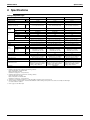
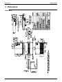
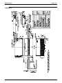
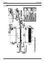
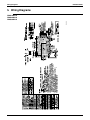
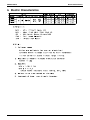
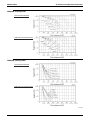
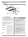
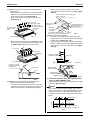
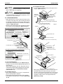
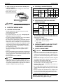
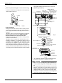
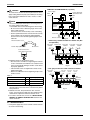
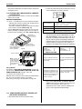
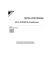
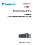
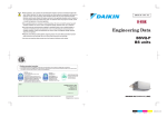
EDUS 39 - 600 - F5 FXHQ-M Ceiling Suspended Type AMERICAS EDUS39-600-F5 FXHQ-M Ceiling Suspended Type 1. 2. 3. 4. 5. 6. 7. Features ......................................................................................................2 Specifications ..............................................................................................3 Dimensions .................................................................................................4 Piping Diagrams..........................................................................................7 Wiring Diagrams..........................................................................................8 Electric Characteristics................................................................................9 Capacity Tables ........................................................................................10 7.1 Cooling Capacity ........................................................................................ 10 7.2 Heating Capacity ........................................................................................ 11 8. Air Velocity and Temperature Distributions...............................................12 9. Sound Levels ............................................................................................15 10.Installation .................................................................................................16 11.Accessories...............................................................................................34 FXHQ-M 1 Features EDUS39-600-F5 1. Features External Appearance Slim body with quieter and wider air flow Adoption of newly designed QUIET STREAM FAN Uses the new quiet stream fan and many more quiet technologies. Sound absor ption member Turbulent flow is produced New quiet stream fan Straightening vane Low operating sound (dB(A)) Class 12 24 36 Operating sound (H/L) 42/38 44/42 46/42 Wide air discharge openings produce a spreading 100° air flow Maintenance is easy New Non-dew Louver Bristle-free Louver minimizes contamination and makes cleaning simpler. Easy to clean flat design New model 100 Non-dew Louver Maintenance is easier because everything can be performed from below the unit A long-life filter (maintenance free up to one year) is equipped as standard 2 FXHQ-M EDUS39-600-F5 Specifications 2. Specifications Ceiling Suspended Type FXHQ12MVJU FXHQ24MVJU FXHQ36MVJU Cooling Capacity1 Model Btu/h 12,000 24,000 36,000 Heating Capacity2 Btu/h 13,500 27,000 40,000 White (10Y9/0.5) White (10Y9/0.5) White (10Y9/0.5) in (mm) 7-11/16×37-13/16×26-3/4” (177.8 x 954.9 x 679.5 mm) 7-11/16×55-1/8×26-3/4” (177.8 x 1400.2 x 679.5 mm) 7-11/16×62-5/8×26-3/4” (177.8 x 1590.7 x 679.5 mm) 2×12×15 3×12×15 2×12×15+2×10×15 ft² (m²) 1.96’ (0.60 m) 3.15’ (0.96 m) 3.66+2.95’ (1.11+0.90 m) Model 3D12K1AA1 3D12K2AA1 ⎯⎯⎯⎯⎯⎯⎯⎯ Type Sirocco Fan Sirocco Fan Sirocco Fan kW 0.06 0.13 0.13 CFM 410/340 710/600 830/670 Casing Color Dimensions: (H × W × D) Coil (Cross Fin Coil) Fan Rows × Stages × FPI Face Area Motor Output Air Flow Rate (H/L) Drive Temperature Control Sound Absorbing Thermal Insulation Material Air Filter Piping Connections Direct Drive Direct Drive Direct Drive Microprocessor Thermostat for Cooling and Heating Microprocessor Thermostat for Cooling and Heating Microprocessor Thermostat for Cooling and Heating Glass Wool Glass Wool Glass Wool Resin Net (with Mold Resistant) Resin Net (with Mold Resistant) Resin Net (with Mold Resistant) Liquid Pipes in (mm) φ1/4” / 6.4 mm (Flare Connection) φ 3/8” / 9.5 mm (Flare Connection) φ 3/8” / 9.5 mm (Flare Connection) Gas Pipes in (mm) φ1/2” / 12.7 mm (Flare Connection) φ 5/8” / 15.8 mm (Flare Connection) φ 5/8” / 15.8 mm (Flare Connection) Drain Pipe in (mm) VP20 External Dia. 1” / 25.4 mm Internal Dia. 3/4” / 19.1 mm VP20 External Dia. 1” / 25.4 mm Internal Dia. 3/4” / 19.1 mm VP20 External Dia. 1” / 25.4 mm Internal Dia. 3/4” / 19.1 mm Machine Weight (Mass) Lbs 55 80 90 Sound Level (H)4 dBA 42 44 46 Fuse Thermal Protector for Fan Motor Fuse Thermal Protector for Fan Motor Fuse Thermal Protector for Fan Motor Electronic Expansion Valve Electronic Expansion Valve Electronic Expansion Valve R-410A Series R-410A Series R-410A Series Operation Manual, Installation Manual, Drain Hose, Paper Pattern for Installation, Clamp Metal, Insulation for Fitting, Clamps, Washers. Operation Manual, Installation Manual, Drain Hose, Paper Pattern for Installation, Clamp Metal, Insulation for Fitting, Clamps, Washers. Operation Manual, Installation Manual, Drain Hose, Paper Pattern for Installation, Clamp Metal, Insulation for Fitting, Clamps, Washers. Safety Devices Refrigerant Control Connectable Outdoor Unit Standard Accessories Drawing No. C:4D049326 Notes: 1. Nominal cooling capacities are based on the following conditions: Return air temperature: 80°FDB, 67°FWB Outdoor temperature: 95°FDB Equivalent ref. piping: 25ft / 7.5 m (Horizontal) 2. Nominal heating capacities are based on the following conditions: Return air temperature: 70°FDB. Outdoor temperature: 47°FDB, 43°FWB Equivalent ref. piping: 25ft / 7.5 m (Horizontal) 3. Capacities are net, including a deduction for cooling (an addition for heating) for indoor fan motor heat. 4. Anechoic chamber conversion value, measured under JISB8616 conditions. During actual operation, these values are normally somewhat higher as a result of ambient conditions. 5. Refer to page 9 for Fan Motor Input. FXHQ-M 3 Dimensions EDUS39-600-F5 3. Dimensions 3D049330 FXHQ12MVJU 4 FXHQ-M EDUS39-600-F5 Dimensions 3D049331 FXHQ24MVJU FXHQ-M 5 Dimensions EDUS39-600-F5 3D049332 FXHQ36MVJU 6 FXHQ-M EDUS39-600-F5 Piping Diagrams 4. Piping Diagrams Gas piping connection port Heat exchanger R3T R1T Fan R2T Liquid piping connection port Filter Electronic Filter expansion valve C:4D024460A R1T : Thermistor for suction air temperature R2T : Thermistor for liquid line temperature R3T : Thermistor for gas line temperature FXHQ-M Capacity GAS 12M φ1/2” Liquid φ1/4” 24/36M φ5/8” φ3/8” 7 Wiring Diagrams EDUS39-600-F5 5. Wiring Diagrams 3D048116 FXHQ12MVJU FXHQ24MVJU FXHQ36MVJU 8 FXHQ-M EDUS39-600-F5 Electric Characteristics 6. Electric Characteristics C:4D049333 FXHQ-M 9 Capacity Tables EDUS39-600-F5 7. Capacity Tables 7.1 Cooling Capacity FXHQ-M Cooling capacity Indoor Air Temp. °FWB Unit size Outdoor air temp. °FDB 12 24 36 75 79 83 87 91 95 99 103 75 79 83 87 91 95 99 103 75 79 83 87 91 95 99 103 61 64 67 70 72 75 TC SHC TC SHC TC SHC TC SHC TC SHC TC SHC MBh MBh MBh MBh MBh MBh MBh MBh MBh MBh MBh MBh 9.5 9.5 9.5 9.5 9.5 9.5 9.5 9.5 18.9 18.9 18.9 18.9 18.9 18.9 18.9 18.9 28.4 28.4 28.4 28.4 28.4 28.4 28.4 28.4 8.5 8.5 8.5 8.5 8.5 8.5 8.5 8.5 15.3 15.3 15.3 15.3 15.3 15.3 15.3 15.3 21.8 21.8 21.8 21.8 21.8 21.8 21.8 21.8 10.7 10.7 10.7 10.7 10.7 10.7 10.7 10.7 21.5 21.5 21.5 21.5 21.5 21.5 21.5 21.5 32.2 32.2 32.2 32.2 32.2 32.2 32.2 32.2 8.8 8.8 8.8 8.8 8.8 8.8 8.8 8.8 16.6 16.6 16.6 16.6 16.6 16.6 16.6 16.6 23.9 23.9 23.9 23.9 23.9 23.9 23.9 23.9 12.0 12.0 12.0 12.0 12.0 12.0 12.0 12.0 24.0 24.0 24.0 24.0 24.0 24.0 24.0 24.0 36.0 36.0 36.0 36.0 36.0 36.0 36.0 36.0 9.4 9.4 9.4 9.4 9.4 9.4 9.4 9.4 17.1 17.1 17.1 17.1 17.1 17.1 17.1 17.1 25.1 25.1 25.1 25.1 25.1 25.1 25.1 25.1 13.3 13.3 13.3 13.2 13.0 12.7 12.5 12.3 26.5 26.5 26.5 26.4 25.9 25.5 25.0 24.6 39.8 39.8 39.8 39.5 38.9 38.2 37.5 36.8 9.7 9.7 9.7 9.6 9.6 9.4 9.5 9.2 17.8 17.8 17.8 17.7 17.5 17.4 17.1 17.0 26.0 26.0 26.0 26.0 25.7 25.3 25.1 24.8 14.0 13.8 13.6 13.3 13.1 12.9 12.7 12.4 28.0 27.6 27.1 26.7 26.2 25.8 25.3 24.9 42.1 41.4 40.7 40.0 39.4 38.7 38.0 37.3 10.0 9.6 9.6 9.3 9.4 9.3 9.3 8.8 18.1 18.0 17.7 17.2 17.2 17.1 16.9 16.8 26.5 26.1 25.8 25.5 25.2 24.6 24.6 24.3 14.3 14.0 13.8 13.6 13.4 13.1 12.9 12.7 28.5 28.1 27.6 27.2 26.7 26.3 25.8 25.4 42.8 42.1 41.5 40.8 40.1 39.4 38.8 38.1 9.3 9.3 9.0 9.0 9.0 8.9 8.9 8.7 17.2 17.0 16.8 16.4 16.6 16.2 16.1 15.7 25.1 24.7 24.4 24.4 24.1 23.7 23.2 22.8 TC : Total capacity ; kW SHC : Sensible heat capacity ; kW Refer to Outdoor Unit Capacity Tables : for the actual performance data of each indoor and outdoor unit combination. 10 FXHQ-M EDUS39-600-F5 7.2 Capacity Tables Heating Capacity FXHQ-M Heating Capacity Indoor Air Temp. °FDB Indoor unit Outdoor Air Temp. °FDB 12 24 36 22.0 26.0 30.0 35.0 39.0 44.0 47.0 51.0 54.0 57.0 60.0 22.0 26.0 30.0 35.0 39.0 44.0 47.0 51.0 54.0 57.0 60.0 22.0 26.0 30.0 35.0 39.0 44.0 47.0 51.0 54.0 57.0 60.0 °FWB 20.0 24.0 28.0 32.0 36.0 40.0 43.0 47.0 50.0 53.0 56.0 20.0 24.0 28.0 32.0 36.0 40.0 43.0 47.0 50.0 53.0 56.0 20.0 24.0 28.0 32.0 36.0 40.0 43.0 47.0 50.0 53.0 56.0 62 65 68 70 72 75 TC TC TC TC TC TC MBh MBh MBh MBh MBh MBh 11.7 12.2 12.8 13.3 13.9 14.5 14.9 15.4 15.5 15.5 15.5 23.3 24.5 25.6 26.7 27.8 28.9 29.7 30.8 31.0 31.0 31.0 35.0 36.7 38.4 40.0 41.7 43.4 44.6 46.3 46.5 46.5 46.5 11.7 12.2 12.8 13.3 13.9 14.4 14.7 14.7 14.7 14.7 14.7 23.3 24.4 25.5 26.6 27.7 28.9 29.5 29.5 29.5 29.5 29.5 35.0 36.6 38.3 40.0 41.6 43.3 44.2 44.2 44.2 44.2 44.2 11.6 12.2 12.7 13.3 13.9 14.0 14.0 14.0 14.0 14.0 14.0 23.3 24.4 25.5 26.6 27.7 28.0 28.0 28.0 28.0 28.0 28.0 34.9 36.6 38.2 39.9 41.6 42.0 42.0 42.0 42.0 42.0 42.0 11.6 12.2 12.7 13.3 13.5 13.5 13.5 13.5 13.5 13.5 13.5 23.2 24.3 25.5 26.6 27.0 27.0 27.0 27.0 27.0 27.0 27.0 34.8 36.5 38.2 39.8 40.0 40.0 40.0 40.0 40.0 40.0 40.0 11.6 12.2 12.7 13.0 13.0 13.0 13.0 13.0 13.0 13.0 13.0 23.2 24.3 25.4 26.0 26.0 26.0 26.0 26.0 26.0 26.0 26.0 34.8 36.5 38.1 39.0 39.0 39.0 39.0 39.0 39.0 39.0 39.0 11.6 12.1 12.3 12.3 12.3 12.3 12.3 12.3 12.3 12.3 12.3 23.2 24.3 24.5 24.5 24.5 24.5 24.5 24.5 24.5 24.5 24.5 34.7 36.4 36.8 36.8 36.8 36.8 36.8 36.8 36.8 36.8 36.8 Refer to Outdoor Unit Capacity Tables : for the actual performance data of each indoor and outdoor unit combination. FXHQ-M 11 Air Velocity and Temperature Distributions EDUS39-600-F5 8. Air Velocity and Temperature Distributions FXHQ12M <Cooling mode> AIRFLOW DISTRIBUTIONS TEMPERATURE DISTRIBUTIONS FXHQ12M <Heating mode> AIRFLOW DISTRIBUTIONS TEMPERATURE DISTRIBUTIONS 3D052938 12 FXHQ-M EDUS39-600-F5 Air Velocity and Temperature Distributions FXHQ24M <Cooling mode> AIRFLOW DISTRIBUTIONS TEMPERATURE DISTRIBUTIONS FXHQ24M <Heating mode> AIRFLOW DISTRIBUTIONS TEMPERATURE DISTRIBUTIONS 3D052939 FXHQ-M 13 Air Velocity and Temperature Distributions EDUS39-600-F5 FXHQ36M <Cooling mode> AIRFLOW DISTRIBUTIONS TEMPERATURE DISTRIBUTIONS FXHQ36M <Heating mode> AIRFLOW DISTRIBUTIONS TEMPERATURE DISTRIBUTIONS 3D052940 14 FXHQ-M EDUS39-600-F5 Sound Levels 9. Sound Levels Overall Ceiling Suspended Type Notes: Operation noise differs with operation and ambient conditions. dBA Model 208~230V, 60Hz H L FXHQ12MVJU 38 33 FXHQ24MVJU 44 36 FXHQ36MVJU 46 41 Octave Band Level 208V~230V FXHQ12MVJU FXHQ24MVJU 4D052512 FXHQ-M FXHQ36MVJU 4D052513 4D052514 15 Installation EDUS39-600-F5 10. Installation Installation Example Air flow flap (at air outlet) Air outlet Discharge air Drain pipe Refrigerant pipe Inlet air Connection electric wire Suction grille Air filter (inside suction grille) Remote controller Grounding wire Wire from the unit into the ground to prevent electric shock. 1. SAFETY CONSIDERATIONS Read these SAFETY CONSIDERATIONS carefully before installing air conditioning equipment, and be sure to install it correctly. After completing the installation, make sure that the unit operates properly during the start-up operation. Instruct the customer how to operate and maintain the unit. Inform customers that they should store this Installation Manual with the Operation Manual for future reference. Always use a licensed installer or contractor to install this product. Improper installation can result in water or refrigerant leakage, electrical shock, fire, or explosion. Meanings of DANGER, WARNING, CAUTION, and NOTE symbols are as follows: DANGER .............. Indicates an imminently hazardous situation which, if not avoided, will result in death or serious injury. WARNING ............ Indicates a potentially hazardous situation which, if not avoided, could result in death or serious injury. CAUTION ...............Indicates a potentially hazardous situation which, if not avoided, may result in minor or moderate injury. It may also be used to alert against unsafe practices. NOTE .................... Indicates situations that may result in equipment or propertydamage accidents only. 16 3PN02401-9X DANGER • Refrigerant gas is heavier than air and displaces oxygen. A massive leak can lead to oxygen depletion, especially in basements, and an asphyxiation hazard can occur leading to serious injury or death. • Do not install unit in an area where flammable materials are present due to risk of explosions that can cause serious injury or death. Refrigerant gas may produce toxic gas if it comes in contact with fire from a fan, heater, stove, cooking device, or other heat source. Exposure to this gas can cause severe injury or death. • If equipment utilizing a burner is used in the same room as the air conditioner, there is the danger of oxygen deficiency which can lead to an asphyxiation hazard resulting in serious injury or death. Be sure to sufficiently ventilate the room to avoid this hazard. • Any abnormalities in the operation of the air conditioner, such as smoke or fire, can result in severe injury or death. Turn off the power and contact your dealer immediately for instructions. • If equipment utilizing a burner is used in the same room as the air conditioner, there is the danger of oxygen deficiency which can lead to an asphyxiation hazard resulting in serious injury or death. Be sure to sufficiently ventilate the room to avoid this hazard. • After completing the installation work, check that the refrigerant gas does not leak. Refrigerant gas may produce toxic gas if it comes in contact with fire from a fan, heater, stove, cooking device, or other heat source. Exposure to this gas can cause severe injury or death. FXHQ-M EDUS39-600-F5 • Do not ground units to water pipes, telephone wires, or lightning rods because incomplete grounding can cause a severe shock hazard resulting in severe injury or death. Do not ground units to gas pipes because a gas leak can result in an explosion which could lead to severe injury or death. • Children playing with plastic bags face the danger of death by suffocation. Tear apart and throw away plastic packaging bags so that children cannot play with them. . Installation • • WARNING • Ask your dealer or qualified personnel to carry out installation work. Do not try to install the machine by yourself. Improper installation may result in water leakage, electric shocks, or fire. • Perform installation work in accordance with this installation manual. Improper installation may result in water leakage, electric shocks, or fire. • Be sure to use only the specified accessories and parts for installation work. Failure to use the specified parts may result in water leakage, electric shocks, fire, or the unit falling. • Check the unit stand for damage on a continual basis, especially if it has been used for a long time. If left in a damaged condition, the unit may fall and cause injury. • Do not touch the air outlet or the horizontal louvers while the swing louver is in operation as fingers may get caught and injured. • Carry out the specified installation work after taking into account strong winds, typhoons, or earthquakes. Improper installation work may result in the equipment falling and causing accidents. • Make sure that a separate power supply circuit is provided for this unit and that all electrical work is carried out by qualified personnel according to local laws and regulations, and this installation manual. An insufficient power supply capacity or improper electrical construction may lead to electric shocks or fire. • Make sure that all wiring is secured, the specified wires are used, and that no external forces act on the terminal connections or wires. Improper connections or installation may result in fire. • When wiring the power supply and connecting the remote controller wiring and transmission wiring, position the wires so that the electric parts box lid can be securely fastened. Improper positioning of the electric parts box lid may result in electric shocks, fire, or the terminals overheating. • Before touching electrical parts, turn off the unit. • Be sure to establish a ground. Do not ground the unit to a utility pipe, arrester, or telephone ground. Incomplete ground may cause electrical shock, or fire. A high surge current from lightning or other sources may cause damage to the air conditioner. • Do not touch the switch with wet fingers. FXHQ-M • • • • Touching a switch with wet fingers can cause electric shock. Be sure to install a ground leakage breaker. Failure to install a ground leakage breaker may result in electric shocks, or fire. Do not install the air conditioner in the following locations: (a) Where a mineral oil mist or oil spray or vapor is produced, for example, in a kitchen. Plastic parts may deteriorate and fall off or result in water leakage. (b) Where corrosive gas, such as sulfurous acid gas, is produced. Corroding copper pipes or soldered parts may result in refrigerant leakage. (c) Near machinery emitting electromagnetic waves Electromagnetic waves may disturb the operation of the control system and result in a malfunction of the equipment. Do not allow children to play on or around the unit as they could be injured. Placing a flower vase or other containers with water or other liquids can result in a shock hazard or fire if a spill occurs. Do not remove the front panel because some parts are dangerous to touch. In addition, some parts may be damaged. For checking and adjusting internal parts, contact your dealer. Do not put a finger or other objects into the air inlet or air outlet. The fan is rotating at high speed and injury can result. CAUTION • Ensure proper drainage by installing drain pipe with thermal insulation to prevent condensate. Improper drain pipe may result in water leakage and property damage. • Be very careful about product transportation. Some products use PP bands for packaging. Do not use any PP bands for a means of transportation. It is dangerous. • Do not turn off the power immediately after stopping operation. Always wait at least 5 minutes before turning off the power. Otherwise, water leakage or other problems may occur. Take adequate measures to prevent the outdoor unit from being as a shelter by small animals. NOTE • Install the indoor and outdoor units, power supply wiring, and connecting wires at least 3.5 ft. away from televisions or radios in order to prevent image interference or noise. (Depending on the radio waves, a distance of 3.5 ft. may not be sufficient to eliminate the noise.) • Remote controller (wireless kit) transmitting distance is shorter than expected in rooms with electronic fluorescent lamps 17 Installation Install the indoor unit as far away from fluorescent lamps as possible. • Arrange the drain hose to ensure smooth drainage. Incomplete drainage may cause leaks in the building and on furniture. • Radio interference may result if installed too close to other electrical devices. • Dismantling of the unit, and treatment of the refrigerant, oil, and other parts, should be done in accordance with the relevant local and national regulations. EDUS39-600-F5 2. BEFORE INSTALLATION • When moving the unit while removing it from the packing case, be sure to lift it by the four hanger brackets. Avoid putting any pressure on other parts especially the refrigerant piping. • Be sure to check the type of R-410A refrigerant to be used before installing the unit as using an incorrect refrigerant will prevent normal operation of the unit. • The accessories needed for installation must be retained in your custody until the installation work is completed. Do not discard them! • Decide upon a line of transport. • Leave the unit inside its packaging until reaching the installation site. Where unpacking is unavoidable, use a sling of soft material or protective plates together with a rope when lifting, to avoid damage or scratches to the unit. • When moving the unit after opening, hold the unit by the hanger brackets (× 4). Do not apply force to the refrigerant piping, drain piping or plastic parts. • For the installation of an outdoor unit, refer to the installation manual attached to the outdoor unit. • Do not install or operate the unit in the following areas: • Kitchens or rooms that might be laden with mineral oil, or filled with oil vapor or spray. Plastic parts may deteriorate and eventually cause the unit to fall out of place or leaks. • Where sulfurous or other corrosive gas exists. Copper tubing and brazed spots may corrode and lead to refrigerant leaks. • Where machines generate electromagnetic waves and cause the control system to malfunction. • Where the air contains high levels of salt as near the ocean, and where voltage fluctuates greatly as in factories. Also in vehicles or vessels. • This unit, both indoor and outdoor, is suitable for installation in a commercial and light industrial environment. If installed as a household appliance, it could cause electromagnetic interference. WARNING • Entrust installation to the place of purchase or a qualified serviceman. Improper installation can result in leaks or even electric shock or fire. • Use of unspecified parts could result in the unit falling, leaks, or even electric shock or fire. NOTE • Be sure to read this manual before installing the indoor unit. • Be sure to procure an air filter in the field and mount it in the suction air passage to prevent water leaks or other problems. 18 FXHQ-M EDUS39-600-F5 Installation 2-1 ACCESSORIES Check that the following accessories are included with your unit. Name (1) Drain pipe Quantity 1 pc. (2) Metal clamp (3) Washer for hanger bracket (4) Clamp 8 pcs. 9 pcs. 1 pc. Does the power supply voltThe unit may malfunction or age correspond to that the components burn out. shown on the name plate? Are wiring and piping correct? The unit may malfunction or the components burn out. Is the unit safely grounded? Electric shock. Is wiring size according to specifications? The unit may malfunction or the components burn out. Is something blocking the air outlet or inlet of either Insufficient cooling. the indoor or outdoor units? Shape Name (5) Paper pattern for installation Quantity 1 pc. Insulation pipe cover Sealing pad 1 each 1 each (6) For gas pipe (8) Large Are refrigerant piping length The refrigerant charge in the and additional refrigerant system is not clear. charge noted down? b. Items to be checked at time of delivery ∗ Also review the SAFETY CONSIDERATIONS Shape (7) For liquid pipe (9) Small Items to be checked Check Did you explain about operations while showing the operation manual to your customer? Name (10) Resin bush (11) Insulating tube Quantity 1 pc. 3 pcs. For wire Shape Did you give the instruction manual to your customer? (Other) • Operation manual • Installation manual 2-2 OPTIONAL ACCESSORIES • The remote controller part numbers options . are shown in the following Table 1: • Select a wired or wireless remote controller according to customer request and install in an appropriate place. Table 1 Remote controller Wired type BRC1D71 Wireless type BRC7E83 NOTE • If you wish to use a remote controller that is not listed in Table 1, select a suitable remote controller after consulting catalogs and technical materials. FOR THE FOLLOWING ITEMS, TAKE SPECIAL CARE DURING CONSTRUCTION AND CHECK AFTER INSTALLATION IS FINISHED. a. Items to be checked after completion of work Items to be checked Results of improper installaCheck tion: Are the indoor and outdoor unit fixed firmly? Units may drop, vibrate, or make noise. Is the gas leak test finished? Insufficient cooling. Is the unit fully insulated? Condensate water may drip. Does drainage flow smoothly? Condensate water may drip. FXHQ-M 2-3 NOTE TO THE INSTALLER Be sure to instruct customers how to properly operate the unit (especially cleaning filters, operating different functions, and adjusting the temperature) by having them carry out operations themselves while looking at the manual. 3. SELECTING INSTALLATION SITE Attach an additional insulation pipe cover to the unit body when it is believed that the relative humidity in the ceiling exceeds 80%. Use glass wool, polyethylene foam, or something similar with a minimum 3/8 inch thickness as insulation. (1) Select an installation site where the following conditions are fulfilled: • Optimum air distribution can be ensured. • Nothing blocks air passage. • Condensate can be properly drained. • Ceiling is strong enough to bear the indoor unit weight. • False ceiling is not noticeably on an incline. • Sufficient clearance for maintenance and service can be ensured. DANGER • Do not install unit in an area where flammable materials are present due to risk of explosion resulting in serious injury or death. WARNING • If the supporting structural members are not strong enough to take the unit’s weight, the unit could fall out of place and cause serious injury. (1-1) When a margin is in the space of the ∗ section, ser- vice and maintenance work will become still easier if it vacates 7 7/8 in. or more. 19 Installation EDUS39-600-F5 ∗ 1 3/16 or more ∗ 1 3/16 or more 4. PREPARATIONS BEFORE INSTALLATION (1) Relative position of holes for indoor unit, suspension bolt position, piping, and wiringg. Wiring hole Rear side pipe hole Air inlet Obstruction Floor 6 5 5/8 F G H A (Indoor unit) B (Suspension bolt pitch) C D (Length : in.) units is within the allowable limit. Refer to the installation manual for the outdoor unit. (1-3) Install the indoor and outdoor units, power wire, and connecting wires at least 3.5 ft. away from televisions or radios in order to prevent image interference or noise. Depending on the radio waves, a distance of 3.5 ft. may not be sufficient enough to eliminate the noise. (2) Use suspension bolts for installation. Check if the ceiling is strong enough to support the weight of the unit. If there is a risk, reinforce the ceiling before installing the unit. Installation pitch is marked on the paper pattern for installation. Refer to it to check for points requiring reinforcing. (3) This product may be installed on ceilings up to 10.6 feet from the floor. (4) A direction of installation. • Refrigerant piping: the rear side, right side, or upper part. • Wiring: only the rear side. • Drain piping: the rear right side or the right side. Installation is not possible at rear left. 26 3/4 (Indoor unit) 10 1/4 (Suspension bolt pitch) 8 1/4 (1-2) Ensure that the pipe between indoor and outdoor Drain pipe hole Conduit hole 6 1/4 7 1/4 Required service space Front view 12 or more Air outlet 3 3/4 6 1/4 E False ceiling view Top gas pipe hole Suspension bolt (× 4) Top liquid pipe hole Air outlet Model A B FXHQ12MVJU 37 13/16 36 1/4 FXHQ24MVJU 55 1/8 53 1/2 FXHQ36MVJU 62 5/8 61 (length : in.) C D E F G H 14 3/4 12 1/4 13 3/4 9 5/8 13 3/8 15 1/4 23 1/2 20 7/8 22 3/8 18 1/4 22 23 15/16 27 3/16 24 5/8 26 1/8 22 25 3/4 27 11/16 (2) Drill holes for suspension bolts, refrigerant, drain pipe, and wire. • Refer to the paper pattern for installation. • Select the location for each of the holes and make the holes in the ceiling. (3) Remove the parts from the indoor unit. (3-1) Detach the suction grille. • Slide the locking knobs (×2) on the suction grille inward (direction of arrows) and lift upwards. (Refer to Fig. 1) • With the suction grille open, remove the suction grille forward, holding on to the rear tabs (×2) on the suction grille. (Refer to Fig. 2) Knob Suction grille Fig. 1 Tab Suction grille Fig. 2 20 FXHQ-M EDUS39-600-F5 Installation (3-2) Remove the decoration panels (left and right) and the protection net. • After removing the securing screws for the decoration panels (one each), pull them forward in the direction of the arrowand remove them. (Refer to Fig. 3) • Remove the securing screws for the protection net. (Refer to Fig. 3) Protection net securing screws (M4) Decoration panel securing screws (M4) Decoration panel securing screw (M4) Decoration panel • When setting the refrigerant pipe to the rear side, remove the securing screws and the metal plate. (Refer to Fig. 6) After removing, attach the resin bush (Refer to Fig. 26) Removable part (metal plate) If setting the drain pipe to the right side, block up the hole for drain pipe with pate etc. Metal plate securing screw (M4) If setting the refrigerant pipe to the rear side, remove this metal plate. Decoration panel Fig. 3 • Raise one side of the protection net upwardin the direction of the arrow (i) and remove back toward the arrow (ii). (Refer to Fig. 4, 5)Take out the accessories. (ii) Fig. 6 (3-4) Remove the hanger brackets. • Loosen the 2 bolts (M8) used to attach the hanger brackets which are on each side (4 places left and right) to within 3/8 in.. (Refer to Fig. 7, 8) • After removing the securing screws (M5) for the hanger brackets on the rear side, pull the hanger brackets back in the direction of the arrow, and remove them. (Refer to Fig. 8) Accessories Protection net (i) Decoration panel Length of loosening should be less than 3/8 Indoor unit 3/8 or less Fig. 4 Decoration panel Fig. 7 If it raises too much, a hook stops catching and falling out. Protection net (i) Hanger bracket (Length : in.) • (ii) Hanger bracket fixing screw (M5) Hook Hanger bracket setting bolt (M8) Hanger bracket Fig. 5 (3-3) Remove the rear metal plate for transmission wire, remote controller wire and refrigerant pipe. • It is necessary to drill the knock out hole in the removable part. Knock down several times with a punch and hammer and remove the removable part with pliers. Fig. 8 (4) Attach the suspension bolts. Use suspension bolts which are W3/8 or M8-M10 in size. • Adjust the distance of the suspension bolts from the ceiling in advance. (Refer to Fig. 9) NOTE • Use a hole-in anchor for existing ceilings, and a sunken insert, sunken anchor or other field supplied parts for new ceilings to reinforce the ceiling to bear the weight of the unit. Adjust clearance from the ceiling before proceeding further. Ceiling slab 1–2 3/16 Anchor FXHQ-M Suspension bolt False ceiling All the above parts are field supplied. (Length : in.) Fig. 9 21 Installation 5. EDUS39-600-F5 INDOOR UNIT INSTALLATION It may be easier to attach accessory parts before installing the indoor unit. Therefore, please also read the instruction manuals provided with the accessory parts. As for the parts to be used for installation work, be sure to use the provided accessories and specified parts designated by Daikin AC. (1) Secure the hanger brackets to the suspension bolts. (Refer to Fig. 10) Refer to Figure 10. (5) When hanging the indoor unit main body, be sure to use a level or a plastic tube with water in it to make sure the drain piping is set either level or slightly tilted to ensure proper drainage. Refer to Fig. 12 A 1˚ or less B 1˚ or less NOTE • To ensure they are safely secured, use the included washers, and secure them with double. (2) While sliding the main body from the front, lift it and insert the bolts (M8) for the hanger brackets into the attachment part on the hanger brackets. (Refer to Fig. 11) (3) Fasten the bolts for the hanger brackets (M8) securely in 4 places, left and right. (Refer to Fig. 11) (4) Replace the screws for the hanger brackets which had been removed (M5) securely in 2 places left and right. This is necessary to prevent any forward and back slide in the main body of the indoor unit. (Refer to Fig. 11) A.B 1˚ or less Fig. 12 A.When the drain piping is tilted to the right, or to the right and back, do the following: Place it level, or tilt it slightly to the right or the back. (1° or less.) B.When the drain piping is tilted to the left, or to the left and back, do the following: Place it level, or tilt it slightly to the left or the back. (1° or less.) CAUTION Nut (Field supplied) • Setting the unit at an angle opposite to the drain piping might cause a water leakage. Washer (3) (attached) 6. Double nuts (Field supplied) Hanger bracket REFRIGERANT PIPING WORK DANGER Fig. 10 • Refrigerant gas may produce toxic gas if it comes in contact with fire such as from a fan, heater, stove or cooking device. Exposure to this gas could result in severe injury or death. Hanger bracket CAUTION Hanger bracket setting bolt (M8) Hanger bracket fixing screw (M5) Fig. 11 22 Attachment part • Use a pipe cutter and flare suitable for the type of refrigerant. • To prevent dust, moisture, or other foreign matter from infiltrating the tube, either pinch the end or cover it with tape. • Do not allow anything other than the designated refrigerant, such as air, to get mixed into the refrigerant circuit. If any refrigerant gas leaks while working on the unit, immediately ventilate the room thoroughly FXHQ-M EDUS39-600-F5 Installation 6-1 GENERAL INSTRUCTIONS Table 2 6-2 CONNECTING THE REFRIGERANT PIPE • Ensure outdoor unit is charged with refrigerant. • Use copper alloy seamless pipes. • Be sure to use both a spanner and torque wrench together, as shown in the drawing, when connecting or disconnecting pipes to/from the unit. (Refer to Fig. 13) • Refer to Table 2 to determine the proper tightening torque. • Refer to Table 2 for the dimensions of flare shape. • When connecting the flare nut, coat the flare section (both inside and outside) with ester oil or ether oil, rotate three or • four times first, then screw in. (Refer to Fig. 14) Torque wrench φ1/4 10.4–12.7 0.342–0.358 φ3/8 24.1–29.4 0.504–0.520 φ1/2 36.5–44.5 0.638–0.654 φ5/8 45.6–55.6 0.760–0.776 Flare shape (in.) 2˚ Flare dimensions A (in.) 45˚± Tightening torque (ft.lbf) R0.016-0.031 A Pipe size (in.) 90˚± 2˚ • For refrigerant pipe of outdoor units, see the installation manual attached to the outdoor unit. • Execute thermal insulation work completely on both sides of the gas pipe and the liquid pipe or a water leak may occur. . (The temperature of the gas pipe can reach up to approximately 250°F, so use insulation pipe cover that is sufficiently resistant.) • In cases where the temperature and humidity of the refrigerant pipe sections might exceed 86°F or RH 80%, reinforce the thermal insulation (3/4 in. or thicker) or condensate may form on the surface of the insulation pipe cover. Before refrigerant pipe work, check which type of refrigerant is used. Proper operation is not possible if the types of refrigerant are not the same. CAUTION • Overtightening may damage the flare and cause a refrigerant leakage. Not recommended but in case of emergency You must use a torque wrench but if one is not available, you can use the following installation method: When you keep tightening the flare nut with a spanner, there is a point where the tightening torque suddenly increases. From that position, further tighten the flare nut the angle shown below: Table 3 Pipe size (in.) Further tightening angle Recommended arm length of tool (in.) φ1/4 60 to 90 degrees φ3/8 60 to 90 degrees Approx. 7 7/8 φ1/2 30 to 60 degrees Approx. 9 13/16 φ5/8 30 to 60 degrees Approx. 11 13/16 Approx. 5 7/8 After the work is finished, make sure to check that there is no gas leak. Pipe union 6-3 BRAZING REFRIGERANT PIPING Flare nut Spanner Fig. 13 • Use the flare nut include with the main body of the unit. CAUTION • Oil must not adhere to any equipment other than a flare. If oil adheres to resin or other parts, deterioration may occur.. Ester oil or ether oil. Fig. 14 • Do not use flux when brazing refrigerant pipe. Use phosphor copper brazing filler metal (BCuP) which does not require flux. • Flux has an extremely negative effect on refrigerant piping systems. For instance, if chlorine based flux is used, it will cause pipe corrosion. If the flux contains fluorine, it will damage the refrigerant oil. • Before brazing local refrigerant pipe, nitrogen gas shall be blown through the pipe to expel air from the pipe. If brazing is done without nitrogen gas blowing, a large amount of oxide film develops inside the pipe which can cause system malfunction. • When brazing the refrigerant pipe, only begin brazing after having carried out nitrogen substitution or while inserting nitrogen into the refrigerant pipe. Once this is done, connect the indoor unit with a flared or a flanged connection. • Nitrogen should be set to 2.9 psi with a pressure-reducing valve if brazing while inserting nitrogen into the pipe. (Refer to Fig. 15) Refrigerant pipe Part to be brazed Pressure-reducing valve Taping hands valve Nitrogen Fig. 15 FXHQ-M Nitrogen 23 Installation EDUS39-600-F5 DANGER • Use of oxygen may cause an explosion resulting in serious injury or death. Only use nitrogen gas. (3) For piping facing right. • Cut out a slit hole on the decoration panel (right) and set the pipe. (Refer to Fig. 17) CAUTION • Be sure to insulate any field piping all the way to the piping connection inside the unit. Any exposed piping may cause condensate or a burn if touched. Rear-facing refrigerant pipe Right-facing refrigerant piping Rear right-facing drain pipe 6-4 PIPING INSULATION • Make absolutely sure to execute thermal insulation works on the pipe-connecting section after checking gas leakage by thoroughly studying the following figure and using the insulation pipe cover (6) and (7). Fasten both ends with the clamps (4). (Refer to Fig. 16) • Wrap the small sealing pad (9) only around the insulation for the joints on the gas piping side. (Refer to Fig. 16) Right-facing drain pipe Decoration panel (right) removable part If only setting the drain pipe to face right, cut this section only. Fig. 17 w Top plate Procedure for thermal insulation of gas-side pipe Insulation pipe cover for gas pipe (6) Flare nut connection Insulation pipe cover (main unit) Orient so that the end of the wrapped insulation Attach to base pipe cover is facing up Wind around the pipe, beginning at the base. Small sealing pad (9) Top penetration lid Main unit Insulation pipe cover (Locally procured) Clamp (4) This hole not using it. Cut out Insulation pipe cover for gas pipe (6) Fig. 18 (A figure from an inside bottom) Gas pipe Liquid pipe Insulation pipe cover for liquid pipe (7) Clamp (4) (× 4) Attach to the bottom (For both gas pipe and liquid pipe) Procedure for thermal insulation of liquid-side pipe Insulation pipe cover for liquid pipe (7) Flare nut connection Insulation pipe cover (main unit) Orient so that the end of the wrapped insulation Attach to base material is facing up Insulation pipe cover (Locally procured) Main unit Clamp (4) Upward-facing refrigerant pipe L-shaped branch pipe kit (Optional accessories) Fig. 19 Thermistor lead line Top penetration lid clamp section Swing motor lead line Fig. 16 (1) For rear-facing piping: • Remove the rear metal plate for pipe. (Refer to Fig. 17) • The figure shows when both the piping and drain pipe are set facing the back. When setting the piping to face up or right, attach the rear metal plate for refrigerant pipe and plug a hole for drain pipe. See Page 186, Section 4. PREPARATIONS BEFORE INSTALLATION, (3-3). (2) For piping facing up. • When setting the piping to face up, the L-shaped branch pipe kit sold separately is required. • Removing the top penetration lid and use the L-shaped branch pipe kit sold separately to set the pipe. (Refer to Fig. 18, 19) 24 Fig. 20 (A figure from an inside bottom) • When piping is complete, use sissors to cut the removed penetration lid into the shape of the pipe and attach. As when removing the top penetration lid, secure the lead lines for the swing motor and thermistor by passing them through the clamp section on the top penetration lid. (Refer to Fig. 18, 20) FXHQ-M EDUS39-600-F5 Installation • When doing this, block any gaps between the pipe penetration lid and the pipes by using putty to prevent dust from entering the indoor unit. NOTE DRAIN PIPING WORK (1) Carry out the drain piping. • Make sure piping provides proper drainage. • You can select whether to bring the drain piping out from the rear right or right. For rear right-facing and right-facing situations, refer to Section6. REFRIGERANT PIPING WORK on Page 188. • Make sure the pipe diameter is the same or bigger than the branch pipingusing vinyl-chloride piping, nominal diameter 1 in., external diameter 1 1/4 in. • Make sure the piping is short, has at least a 1/100 slope, and can prevent air pockets from forming. (Refer to Fig. 21) • Do not allow any slack to gather in the drain pipe inside the indoor unit as slack in the drain pipe can cause the suction grille to break. • To ensure no excessive pressure is applied to the drain pipe (1), do not bend or twist when installing or leakage can occur. • If converging multiple drain pipes, install according to the procedure shown below. 3 7/8 or more 7. • Insulate the metal clamp bracket and drain pipe from the bottom using the large sealing pad (8). (Refer to Fig. 23) • Be sure to insulate all drain piping running indoors. T-joint converging drain pipes Slope downwards at a gradient (Length : in.) of at least 1/100 Select converging drain pipes with gauges suitable for the unit’s operating capacity. ) Good Tilt down Wrong Wrong Fig. 24 Do not lift Make sure there is no slack Make sure it is not in the water Fig. 21 CAUTION • Water accumulating in the drain piping can cause the drain to clog. • Be sure to use the drain pipe (1) and metal clamp (2). Insert the drain pipe completely into the drain socket, and securely attach the metal clamp bracket inside the gray tape area on the inserted tip of the drain pipe. (Refer to Fig. 22) Screw the screws on the metal clamp bracket until there is 5/32 in. left. Pay attention to the direction of the attachment to prevent the metal clamp bracket from coming into contact with the suction grille. (Refer to Fig. 23) Metal clamp (2) Taping area (Gray) Drain pipe (1) Fig. 22 5/32 or less Large sealing pad (8) Metal clamp (2) < Facing rear right or right > Fig. 23 FXHQ-M (Length : in.) 25 Installation EDUS39-600-F5 (2) Check to make sure the water flows smoothly after piping is complete. • Slowly pour 600ml of drain-checking water into the drain pan through the air outlet. Plastic container for pouring Air outlet 8-2 ELECTRICAL CHARACTERISTICS Units Model Power supply Hz Volts Voltage range 60 208230V Max. 253V Min. 187V FXHQ12MVJU FXHQ24MVJU FXHQ36MVJU MCA MFA Fan motor W FLA 0.8 15 62 0.6 1.0 15 130 0.8 1.4 15 130 1.1 MCA: Min. Circuit Amps (A);MFA: Max. Fuse Amps (A) W: Fan Motor Rated Output (W);FLA: Full Load Amps (A) Make sure not to splash the water. Fig. 25 8-3 SPECIFICATIONS FOR FIELD SUPPLIED FUSES AND WIRES CAUTION • 8. Power supply wiring If water collects on drain pipe it will cause blockage. Model Field fuses Size Remote controller wiring Transmission wiring Wire Size ELECTRIC WIRING WORK FXHQ12MVJU 8-1 GENERAL INSTRUCTIONS • All field-supplied parts, materials, and electrical works must conform to local codes. • Use only copper wire . • For electrical wiring work, refer to the Wiring Diagram Label attached to the control box lid. • For remote controller wiring details, refer to the installation manual attached to the remote controller. • All wiring must be performed by an authorized electrician. • This system consists of multiple indoor units. Mark each indoor unit as unit A, unit B,and so on, and be sure the terminal board wiring to the outdoor unit and BS unit are properly matched. If controls wiring and piping between the outdoor and indoor units are mismatched, a communications malfunction is likely. • An ground leakage circuit breaker capable of shutting down the power supply to the entire system must be installed. • Refer to the installation manual attached to the outdoor unit for the size of power supply wiring connected to the outdoor unit, the capacity of the circuit breaker and switch, and wiring instructions. • Be sure to ground the air conditioner. DANGER • Do not ground units to water pipes, telephone wires, or lightning rods because incomplete grounding can cause a severe shock hazard resulting in severe injury or death. Do not ground to gas pipes because a gas leak can result in an explosion leading to severe injury or death. 2 conducutor, FXHQ24MVJU 15A FXHQ36MVJU Wire size must comply with local codes stranded copper, nonshielded, AWG18-16 PVC or vinyl jacket wire Allowable length of transmission wire between indoor/outdoor units and between the indoor unit and the remote controller wire are as follows. (1) Outdoor unit – Indoor unit: Max. 3280 ft. (Total wire length: 6560 ft.) (2) Indoor unit – Remote controller: Max. 1640 ft. 9. WIRING EXAMPLE AND HOW TO SET THE REMOTE CONTROLLER 9-1 HOW TO CONNECT WIRES CAUTION • Even if the control box lid is removed, pull the remote controller wire, transmission wire, and the power supply wire inside the unit, using conduits for each, so that the wires do not come into contact with the opening section of the metal casing. • Pass conduits through the wall and secure them along with the refrigerant pipe in order to prevent external pressure to transmission wire and power supply wire. • Prevent dust from entering into the unit by filling the gap around the pipe or wire with corking or putty. • Arrange the wires and fix the lid firmly so that it does not float during wiring work. • Do not clamp remote controller wire and transmission wire together with power supply wire. Doing so may cause malfunction. • Remote controller wire, transmission wire, and power supply wire should be located at least 5 inches from other electrical wires. Not following this guideline may result in malfunction due to electrical noise. Method of wiring power supply, units, and connecting remote controller wiring: (Refer to Fig. 27) 26 FXHQ-M EDUS39-600-F5 Installation • Attach the plastic bushing (10) for remote controller wiring. • Insert the conduit for power supply wire in the conduit hole, and fix it with the lock nut. wire together with the transmission wire to the anchor. (Refer to Fig. 27, 28, 29) Refer to Fig. 28 Power supply Remote controller wire teminal block (2P) Transmission and transmission wire Control box terminal block (6P) Ground terminal Power supply wire Gas pipe Lock nut Liquid pipe Drain pipe Clamp (4) Insulating tube (11) Conduit Corking or Putty Resin bush (10) Conduit hole Conduit Resin bush (10) Fig. 26 • Power supply wire Holding the control box lid, loosen the 2 securing screws, remove the control box lid, match up the phases on the power supply terminal block inside (2P), and make the connections. After this is done, use the attached clamp (4) to bind wire between units to the anchor point. (Refer to Fig. 28) • Remote controller wire and transmission wire Holding the control box lid, loosen the 2 securing screws, remove the control box lid. Thread the remote controller wire and transmission wire through the conduit (11), secure with the clamp (4), and cut off conduit (11) to suitable length. The conduit (11) can let the wire pass to a maximum of 2 wires. If there are three or more wires, use another conduit (11). Pull the wires inside through plastic bushing and connect the wires to the transmission terminal block (6P inside the control box. After connecting, use the clamp (4) to bind the remote controller Control box lid secuing screw (2 pcs.) Control box lid L1 L2 POWER SUPPLY power supply How to connect power supply terminal block (2P) Fig. 27 Clamp (4) Ground wire Fastener After securing the cramp material to the bracket, cut off any extra material. Power supply wire Clamp (4) Remote controller wire and transmission wire Fastener Fig. 28 Transmission terminal block (6P) P1 P2 F1 F2 T1 T2 REMOTE CNTRL TRANSMISSION WIRING FORCED OFF Clamp (4) Insulating tube (11) 1 in. Transmission wire Fig. 29 Remote controller wire • The conduit (11) allows the remote controller wire and transmission wire pass to a maximum of 2 wires. WARNING • Never connect power supply wiring to the terminal block for remote controller wiring as this could damage the entire system. • Use only specified wire and connect wires to the terminal tightly. Be careful wires do not place external stress on terminals. Keep wires in neat order so as to not obstruct other equipment. Make sure that the electric box lid fits tightly. Incomplete connections could result in overheating and, in worse cases, result in electric shock or fire. FXHQ-M 27 Installation EDUS39-600-F5 COMPLETE SYSTEM EXAMPLE (3 systems) CAUTION • To avoid a short circuit in the electric parts box, be sure to apply sealing material or putty (not included) to the wiring hole to prevent the infiltration of water, insects, or other small creatures. Power supply Power supply wire Transmission wire Switch Main switch Fuse NOTE BS unit (Only for Heat recovery system) 1. Use round crimp-style terminals for connecting wires to the power-supply terminal block. If unavailable, observe the following points when wiring. • Do not connect wires of different gauges to the same power supply terminal. Looseness in the connection may cause overheating. • Use the specified electric wire. Connect the wire securely to the terminal. Lock the wire down without applying excessive force to the terminal. Tightening torque : 0.97 ft.lbf ±10% Indoor unit Remote controller Fig. 30 1. When using 1 remote controller for 1 indoor unit. (Normal operation) Attach insulation sleeve Electric wire Round crimp-style terminal Power supply 208-230V 60Hz • Control box IN/D OUT/D F1 F2 F1 F2 L1 L2 Power supply 208-230V Power supply 208-230V Outdoor unit L1 L2 L1 L2 60Hz Power supply 208-230V L1 L2 60Hz 60Hz Connect wires of the same gauge to both side. L1 L2 2. Tightening torque for the terminal screws. • Use the correct screwdriver for tightening the terminal screws. If the blade of screwdriver is too small, the head of the screw might be damaged, and the screw will not be properly tightened. • If the terminal screws are tightened too hard, screws might be damaged. • Refer to the table below for the tightening torque of the terminal screws. Table 4 Terminal Size Transmission terminal block (6P) M3.5 0.58 – 0.72 Power supply terminal block (2P) M4 0.87 – 1.06 Ground terminal M4 0.87 – 1.06 P 1 P 2 F 1 F 2 T 1 T2 L1 L2 P 1 P 2 F 1 F2 T 1 T 2 L1 L2 Indoor unit B Indoor unit A P1 P2 P 1 P2 F 1 F 2 T 1 T 2 P1 P2 Fig. 31 P1 P2 Most downstream Indoor unit 2. For group control or use with 2 remote controllers Power supply 208-230V 60Hz Power supply 208-230V Outdoor unit Power supply 208-230V Control box IN/D OUT/D F1 F 2 F 1 F 2 L1 L 2 L1 L2 60Hz L1 L2 60Hz Power supply 208-230V L 1 L2 60Hz Most downstream indoor unit Tightening torque (ft.lbf) L1 L2 3. Do not connect wires of different gauges to the same ground terminal. Looseness in the connection may deteriorate protection. 4. Outside of the unit, keep transmission wire at least 5 inches away from power supply wire. The equipment may malfunction if subjected to external electrical noise. 5. For remote controller wire, refer to the INSTALLATION MANUAL OF REMOTE CONTROLLER attached to the remote controller. P 1 P 2 F 1 F2 T 1 T 2 Indoor unit C P1 P2 Remote controller L1 L2 P 1 P2 F 1 F2 T 1 T 2 Indoor unit A L1 L2 P1 P 2 F1 F 2 T1 T 2 Indoor unit B L1 L2 L1 L2 P1 P2 F1 F2 T1 T2 P1 P2 P1 P2 Remote controller P 1 P2 F1 F2 T1 T2 Indoor unit C Fig. 32 P1 P2 For use with 2 remote controllers 9-2 WIRING EXAMPLE • Fit the power supply wire of each unit with a switch and fuse as shown in the drawing. 28 FXHQ-M EDUS39-600-F5 Installation 3. When including BS unit Power supply 208-230V 60Hz Control box IN/D OUT/D F1 F2 F1 F2 L1 L2 Decoration panel Power supply 208-230V Outdoor unit BS unit L1 L2 60Hz BS unit Control box Control box OUT/D IN/D F1 F2 F1 F2 OUT/D IN/D F1 F2 F1 F2 (ii) Protection net Hook (i) Indoor unit A L1 L2 P 1 P 2 F 1 F2 T 1 T 2 L1 L2 P1 P2 P 1 P 2 F 1 F2 T 1 T 2 (ii) Most downstream indoor unit P1 P2 Hook Remote controller (ii) Fig. 33 (i) NOTE 1. It is not necessary to designate an indoor unit address when using group control. The address is automatically set when power is activated. 2. All transmission wires except for remote controller wires are polarized and must match the terminal symbol. 3. A single switch can be used to supply power to units on the same system but branch switches and branch circuit breakers must be selected carefully. 4. Do not ground the equipment on gas pipes, water pipes, or lightning rods, or crossground with telephones. Improper grounding can result in electric shock. 10. ATTACHING THE SUCTION GRILLE, THE DECORATION PANELS AND THE PROTECTION NET Once wiring is complete, firmly attach the control box lid, the suction grille, the decoration panels, and the protection net in the order opposite to detachment. • Attach the protection net from the way of the hook (i), fix 2 securing screws of the middle of the other side first (ii), then fix the remaining securing screws (iii). (iii) Protection net securing screws (M4) Fig. 34 11. FIELD SETTING Make sure the control box lids are closed on the indoor and outdoor units, and turn on the power. Field setting must be made from the remote controller in accordance with the installation manual. • Setting can be made by changing the Mode No., FIRST CODE NO., and SECOND CODE NO. • For setting and operation, refer to the FIELD SETTING section in the installation manual of the remote controller. 11-1 SETTING AIR FILTER SIGN • Remote controllers are equipped with liquid crystal display air filter signs to display when to clean air filters. • Change the SECOND CODE NO. according to Table 5 depending on the amount of dirt or dust in the room. SECOND CODE NO. is factory set to [01] for air filter contamination-light. Table 5 Setting Spacing time of disFIRST SECOND Mode play air filter sign CODE CODE No. (long life type) NO. NO. Air filter contamination-light Approx. 2500 hrs Air filter contamination-heavy Approx. 1250 hrs 01 10 (20) 0 02 Wireless remote controllers: • When using wireless remote controllers, a wireless remotecontroller address setting is necessary. Refer to the instal FXHQ-M 29 Installation EDUS39-600-F5 lation manual attached to the wireless remote controller for setting instructions. • Connect the input from outside to terminals T1 and T2 of the terminal block for remote controller.. 11-2 CONTROLLING 1 INDOOR UNIT BY 2 REMOTE CONTROLLERS F2 • When using 2 remote controllers, one must be set to MAIN and the other to SUB. MAIN/SUB CHANGEOVER (1) Insert a screwdriver into the recess between the upper and lower part of remote controller and, working from the two positions, pry off the upper part. The remote controller PC board is attached to the upper part of remote controller. (Refer to Fig. 35) • Turn the MAIN/SUB changeover switch on one of the two remote controllers PC boards to [S]. (Leave the switch of the other remote controllers set to [M].) (Refer to Fig. 36) Upper part of remote controller Insert the screw driver here and gently work off the upper part of remote controller. Fig. 35 Lower part of remote controller T1 T2 FORCED OFF Input A Wire specification 2-conductor, stranded, non-shielded copper cable / PVC or vinyl jacket Gauge AWG 18 Length Max. 328 ft. External terminal Contact that can ensure the minimum applicable load of 15 V DC, 10 mA. 2. Actuation • The following table explains FORCED OFF and ON/ OFF OPERATIONS in response to Input A. The T1-T2 terminals are standard on all Daikin indoor units and allow for remote starting and stopping of equipment. Individual indoor units can be field prgrammed at the remote controller to change the T1-T2 sequence of operation of the equipment based upon the application. FORCED OFF (Manual Restart) Mode No. 12 First Code No. 1 Second Code No. 01 ON/OFF OPERATION Mode No. 12 First Code No. 1 Second Code No. 02 DEFAULT SETTING (Factory setting) Only 1 remote controller needs to be changed if factory settings have remained untouched. S M Remote controller PC board S M Input A OFF (Open Circuit) Input A OFF (Open Circuit) An open circuit between terminals T1 and T2 allows the unit to run normally. An open circuit between terminals T1 and T2 prevents unit operation. Input A ON (Closed Circuit) Input A ON (Closed Circuit) Fig. 36 Wiring Method See Section 8. ELECTRICAL WIRING WORK on page 192 and Section9. WIRING EXAMPLE AND HOW TO SET THE REMOTE CONTROLLER on pages 192 to 195. (2) Remove the control box lid. Add 2nd remote controller to the transmission terminal block (P1, P2) in the control box. (There is no polarity.) (Refer to Fig. 29 on page 193 and Table 4 on page 194. A closed circuit between termiClosing the normally open circuit between terminals T1 and nals T1 and T2 allows normal operation of the unit. T2 stops operation of the unit. When T1-T2 is opened, the unit must be restarted with the remote controller. . • How to select FORCED OFF and ON/OFF OPERATION Turn the power on and then use the remote controller to select operation. These codes are programmed at the remote controller. Individual unit groups can be programmed independently. 11-3 COMPUTERIZED CONTROL (FORCED OFF AND ON/OFF OPERATION) 1. Wire specifications and how to perform wiring: 30 FXHQ-M EDUS39-600-F5 Installation 12. TEST OPERATION 11-4 CENTRALIZED CONTROL • For centralized control, it is necessary to designate the Group Number. For details, refer to the manual of each optional controllers for centralized control. SECOND CORD NO. Mode No. FIRST CORD NO. SETTING FIELD SET MODE • Set the remote controller to the FIELD SET MODE. For details, refer to HOW TO SET IN THE FIELD in the remote controller manual. • When in the FIELD SET MODE, select mode No. 12, then set the FIRST CODE NO. to [1]. Then set SECOND CODE NO. to [01] for FORCED OFF and [02] for ON/OFF OPERATION. (FORCED OFF at factory set) Refer to the section TAKE SPECIAL CARE DURING CONSTRUCTION on page 185. • Make sure if the service lids are closed on the indoor and outdoor units. • After finishing the construction of refrigerant pipe, drain pipe, and electric wire, conduct the check operation by referring to the installation manual of the outdoor unit. • The operation lamp of the remote controller will flash when a malfunction occurs. Check the displayed malfunction code to identify the trouble. An explanation of malfunction codes and the corresponding trouble is provided in the installation manual of the outdoor unit. It any of the items in Table 6 are displayed, there may be a problem with the wiring or power, so check the wiring again. Table 6 Remote control display Content “ Under Cen- • There is a short circuit at the FORCED OFF terminals (T1, T2). tralized Control is lit U4 is lit UF is lit • The power on the outdoor unit is off. • The outdoor unit has not been wired for power supply. • Incorrect wiring for the transmission wiring and / or FORCED OFF wiring. • The transmission wiring is cut. No display • The power on the indoor unit is off. • The indoor unit has not been wired for power supply. • Incorrect wiring for the remote controller wiring, the transmission wiring and / or the FORCED OFF wiring. • The remote controller wiring is cut. • If U3 is lit up, the malfunction code shows the check operation has not been performed yet. 12-1 HOW TO DIAGNOSE FOR MALFUNCTION With the power on, it is possible to monitor the type of malfunction by looking at the malfunction code displayed in the remote controller. If nothing is displayed in the remote controller, check the following items before attempting a diagnosis based on the malfunction code, as they might be a cause. • Disconnected or incorrect wiring (between power supply and the outdoor unit, between the outdoor and indoor units, and between the indoor unit and the remote controller) • Burnt out indoor or outdoor unit fuse • “ ” will be displayed for a few seconds on the remote controller immediately after the power is turned on. This display indicates that the remote controller is being checked to see whether it is ok or not, and does not indicate a malfunction. FXHQ-M 31 Installation Diagnose with the display on the liquid crystal display remote controller. 1. With the wired remote controller:. When the operation stops due to trouble, the operation lamp flashes and and the malfunction code is indicated in the liquid crystal display. In such a case, diagnose by referring to the table on the malfunction code list. In case of group control, the unit No. is displayed so that the indoor unit No. with the trouble can be recognized. 2. With the wireless remote controller: Also refer to the operation manual attached to the wireless remote controller. When operation stops, the display on the indoor unit flashes. Diagnose the malfunction code with the following procedures:. (1) Press the INSPECTION /TEST OPERATION button, is displayed and [0] flashes. (2) Press the PROGRAMMING TIME button and find the stopped unit No. Number of beeps 3 short beeps Perform all the following operations 1 short beep Perform (3) and (6) 1 long beep No trouble (3) Press the OPERATION MODE SELECTOR button and upper flashing malfunction code. (4) Continue pressing the PROGRAMMING TIME button until it makes 2 short beeps, and find the upper code. (5) Press the OPERATION MODE SELECTOR button and lower figure of the flashing malfunction code. (6) Continue pressing the PROGRAMMING TIME button until it makes a long beep, and find the lower code. A long beep indicates the malfunction code requires attention. NOTES: 1. Using a wired remote controller: Press the INSPECTION / TEST OPERATION button on remote controller till starts flashing. 2. While in inspection mode, hold down the ON/OFF button for 5 seconds or longer till the above trouble history disappears. After the trouble code goes on and off twice the (normal) code is displayed. EDUS39-600-F5 Order (1) Open gas-side stop valve. (2) Open liquid-side stop valve. (3) Electrify crank case heater for 6 hours. Set to cooling with the remote controller and push (4) “ ON/OFF ” button to start operation. (5) Push“ TEST ”button twice and operate in TEST OPERATION MODE for 3 minutes. (6) Push“ SWING ”button and confirm its operation. (7) Push“ TEST ”button and operate normally. (8) Confirm its function according to the operation manual. 12-2 MALFUNCTION CODE • For places where the malfunction code is left blank, the indication is not displayed. The shaded areas indicate when the unit does not display a malfunction code and continues running even though it might need attention.Be sure to inspect the system and make repairs as necessary. • Depending on the type of indoor or outdoor unit, the malfunction code may or may not be displayed. Code Malfunction/Remarks A1 Micro-computer in PCB is not working A3 Drain level is too high A6 Fan motor error A7 A9 AJ C4 Swing louver motor error Electronic expansion valve drive error Capacity setting error Resistance of indoor unit heat exchanger is abnormal. C5 Sensor R3T for heat exchanger temperature impaired C9 Resistance of indoor unit suction-air thermistor is abnormal. Sensor for remote controller impaired CJ Resistance of the remote controller thermistor is abnormal. E3 Abnormally high pressure (outdoor unit) E4 Abnormally low pressure (outdoor unit) E5 Compressor overheats E7 32 Operation Outdoor fan motor locks E9 Electronic expansion valve impaired (outdoor unit) F3 Outdoor unit discharge temperature is too high F6 Overcharged refrigerant H9 Outdoor air thermistor impaired (outdoor unit) J3 Discharge pipe thermistor impaired (outdoor unit) J5 Suction pipe thermistor impaired (outdoor unit) J6 Heat exchanger thermistor impaired (outdoor unit) J9 Sensor for heat exchanger impaired JA Sensor for high pressure impaired JC Sensor for low pressure is fault. L4 Overheating radiation fin or excessive temperature in power transistor (outdoor) FXHQ-M EDUS39-600-F5 Installation Instantaneous overcurrent (outdoor) L5 L8 L9 Compressor motor grounded or short circuit; inverter PCB error Compressor overcurrent or compressor motor wire cut Compressor possibly locked LC Communication error between inverter and outdoor control unit P1 Open-phase (outdoor) P3 PC board temperature sensor malfunction (outdoor) P4 Radiation fin temperature sensor error PJ Capacity setting error (outdoor) or nothing programmed in the data hold IC. U0 U2 U3 U4 UF U9 UA FXHQ-M Low pressure drop due to insufficient refrigerant or electronic expanison valve error. Power source voltage failure Failure to carry out check operation; transmission error Communication error due to incorrect wiring between indoor unit and outdoor unit, or communication error between outdoor unit and BS unit. Failure to carry out check operation for indoor-outdoor or outdoor-outdoor communications. Communication error between indoor and outdoor unit, or BS unit and indoor/outdoor unit. nation error of indoor/BS/outdoor unit; setting error of spare parts PCB when replaced. 33 Accessories EDUS39-600-F5 11. Accessories Standard Accessories Check that the following accessories are included with your unit. Name (1) Drain pipe (2) Metal clamp (3) Washer for hanger bracket (4) Clamp Quantity 1 pc. 1 pc. 8 pcs. 9 pcs. Shape Name (5) Paper pattern for installation Insulation pipe cover Sealing pad Quantity 1 pc. 1 each 1 each (6) For gas pipe (8) Large (7) For liquid pipe (9) Small Shape Name (10) Resin bush (11) Insulating tube Quantity 1 pc. 3 pcs. For wire Shape • Operation manual • Installation manual 3PN06240-1H Optional Accessories (For Unit) No. Model Item 1 Replacement long-life filter (Resin net) 2 L-type piping kit (for upward direction) FXHQ12MVJU FXHQ24MVJU FXHQ36MVJU KAFJ501D56 KAFJ501D112 KAFJ501D160 KHFP5M35 KHFP5M63 KHFP5M160 3D049335 Op For optional accessories for Controllers, refer to the Controller manual. 34 FXHQ-M EDUS 39 - 600 - F2 FXDQ-M Slim Ceiling Mounted Duct Type AMERICAS 1645 Wallace Drive, Suite 110 Carrollton, TX75006 [email protected] www.daikinac.com May 2007 EDUS39-600-F5 Printed in U.S.A. 05/2007 AMERICAS