1
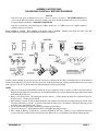
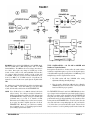
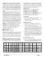
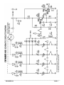
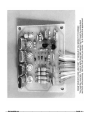
CONSTRUCTION, INSTALLATION, & OPERATION
EXPANDER 160 CRYSTAL OSCILLATOR & SWITCH ©
The EXPANDER 160 is a compact crystal oscillator unit which allows
remote controlled selection of up to four different crystals. This
provides new injection signals for loop mixing in PLL synthesizer
circuits, or additional synthesizer frequencies in 23-channel CB
transceivers. The RF output is approximately 5 V peak-peak when
supplied at +8 VDC, and is buffered to minimize loading at its
connection. Each crystal position includes a series trimmer capacitor
for exact frequency adjustment. Crystal selection is made by diodes,
which eliminates the problem of stray wire capacitance often found in
mechanical switches.
A unique system of wire jumpers allows the EXPANDER 160 to be
used solely as a crystal switch, with the oscillator circuit disconnected.
This configuration is needed for all 23-channel crystal-synthesized
radios, and all 40-channel PLL radios whose crystal frequency is
doubled or tripled before mixing with the VCO signal. In such radios,
the existing crystal is removed from the radio’s chassis, and two
EXPANDER 160 wires are installed at the empty crystal location.
The removed crystal is soldered into the EXPANDER 160 PC board,
along with up to three new crystals. The module is now in series with
the radio’s crystal circuit. This allows up to four crystals (the original
plus your three) to be chosen instead of just the original. The radio’s
total operating range and bandwidth will depend upon the specific
chassis type.
CIRCUIT DESCRIPTION
See the Schematic Diagram on Page 9. The EXPANDER 160 consists
of a Colpitts oscillator, bipolar buffer stage, a diode switching array,
and various jumper wire options.
One of four crystals is chosen when a DC voltage is applied through
your hard switch (toggle, rotary, slide, CB/PA, etc.) to one of the PC
board holes numbered “1” through “4.” The “5” hole is the
common hot side for the hard switch, and connects directly to the
radio’s regulated +DC supply bus. With voltage applied, the
appropriate diode (D1-D4) is turned on by the current flowing
through it and R1/L5 to ground. R1 limits the current to a safe
value. L5 keeps all crystals above RF ground, since the crystal’s hot
side is being switched. RF is decoupled from the DC power supply by
L1-L4 and C1-C4.
OSCILLATOR MODE
The Colpitts oscillator common to CB radios has a relatively high
shunt or parallel input capacitance. This can pull the crystal off
frequency, so series trimmers CT1–CT4 are provided for exact
adjustment after installation. The trimmers have a range of 9-50 pF,
which is more than enough if proper crystals are specified when
ordering.
Jumpers J4-J7 are installed for the OSCILLATOR Mode, and are used
to ground one side of the crystals. Sometimes a particular crystal can
be difficult to trim to the correct frequency. In such cases, you can
often replace the bare jumper wire with a small capacitor (5-68 pF)
or RF choke (1-10 µH) to get the oscillator within the range of the
trimmers.
Q1 is the oscillator. R2, R3, and R4 provide the DC operating biases,
and are chosen to oscillate with any crystal between 10-20 MHz at DC
supply voltages of about +5-12 VDC. C6 is the feedback capacitor
which causes oscillation. The values of C6 and C7 are chosen to
oscillate with any fundamental crystal from approximately 8 MHz to
20 MHz, or any Third Overtone crystal type. (Typically these are in
the 36 MHz range, and are actually cut near 12 MHz.) Q2 is a buffer
stage which isolates the oscillator from possible loading effects in the
radio. C8 has purposely been kept small (22 pF) for this same reason.
DC operating power comes from the radio. The source must be
well regulated for maximum frequency stability. Most CB transceivers
all have at least one such source, usually +5-8 VDC, and this is used to
power the EXPANDER 160. The DC source you choose must be
present for both RX and TX. Connect the RED wire to that, and the
BLACK wire to chassis common.
SWITCH MODE
The EXPANDER 160 is connected as a straight electronic switch in
many PLL radios, and always in the older crystal-synthesized radios.
In this mode J8 is left out, which disconnects the active transistor
stage. J4, J5, J6, and J7 are also removed, and J1, J2, and J3 are
used instead. This ties the low side of all crystals together at hole “A,”
and all the high sides together at hole “B.” In most radios the crystals
are not directly grounded, grounding instead through a Delta Tune
or Clarifier VXO circuit on the crystal’s low side. Thus the jumpers
allow the EXPANDER 160 to be used as a multiple series crystal
switch. Wires from holes “A” and “B” are installed in the appropriate
holes formerly occupied by the original mixing crystal. Crystals are
chosen by diodes D1-D4, in exactly the same way as the
OSCILLATOR Mode.
© Copyright 1983–2002 by L.M. Franklin. All rights reserved.
Published by:
CBC INTERNATIONAL • P.O. BOX 30655 • TUCSON AZ 85751 U.S.A.
TEL/FAX: 888-I-FIX-CBs (1-888-434-9227), (520) 298-7980
Internet: www.cbcintl.com • Email: [email protected]
ASSEMBLY INSTRUCTIONS
PLEASE READ CAREFULLY BEFORE PROCEEDING!
NOTICE
This device will operate as advertised when properly constructed, installed, and adjusted. CBC INTERNATIONAL has no
control over the skill of the purchaser; therefore no warranty can be given. We will repair units built only from our own kits for
$25 prepaid with the returned unit. NO BASKET CASES PLEASE!
This device is intended for educational purposes, 10-Meter Amateur use, or 27 MHz receivers only. Supplier assumes no
liability for improper or illegal use.
Proper soldering is essential. Poor soldering is the biggest cause of problems. Finished joints should look shiny, never dull.
Use only a small iron (25-45 watt) with a very fine round or slot tip to avoid shorts.
Assembly consists of stuffing the parts into the proper PC board holes, as illustrated in the X-Ray View drawing, Page 10. Check against the
schematic circuit diagram if you’re in doubt about the correct holes. Push all parts down tight, wiggling back and forth if necessary as you press
down. (See photo, Page 11.) The diodes and resistors will bend naturally to the proper hole spacing.
NOTES
1. Unless you’re moving the EXPANDER 160 unit from one type of synthesizer circuit to another, you will save time and trouble by
installing the right jumper wires in the first place. Decide which installation type you need, then insert the proper jumpers when stuffing
and soldering all the other parts.
2. Observe correct diode polarity. The banded diode end is the cathode [—]. This is shown in the sketch above and in the X-Ray View.
Diodes also have [—] marks etched on the PCB.
3. Install transistors correctly. See sketch. Match the flat side of the transistor body with the flat side painted on the top of the PC board.
The emitter leads will be to your left.. If in doubt, check against the X-Ray View or the schematic. With the flat side facing you, the
leads will be (left to right) Emitter, Base, Collector.
4. Use cut off parts leads for the jumpers. Determine proper jumpers as described later.
5. Capacitor locations C6, C7, and C8 include extra holes to match different spacings if necessary.
6. Wires: Install the RED in [+], BLACK in [—], and short YELLOW in “RF” holes. An extra 12" wire is included for switch mode
option, as well as the 5-conductor ribbon cable for your switch. Match cable to your switch and crystals with the schematic diagram.
_________________________________________________________________________________________
EXPANDER 160
PAGE 2
CRYSTAL ORDERING
The following specifications should be observed when
ordering crystals.
FREQUENCY:
ACCURACY:
HOLDER TYPE:
CRYSTAL CUT:
LOAD CAPACITANCE:
As desired.
.005% or better.
HC18/U or HC49/U with solder
leads.
Fundamental up to about
20 MHz. Crystals which are
being multiplied in the radio
should be specified as such. (For
example, the 11.325 MHz
crystal
used
in
the
Cobra 148/2000GTL chassis is a
tripler cut type.)
10 pF (series) preferred for easy
adjustment. The 32 pF used in
many CB oscillators can be hard
to net by the trimmer alone.
If you already have crystals with different specs, they can be
tried first and will usually work. If you have the plug-in
HC25/U types, these can also be used by drilling out the PC
board holes to fit their thicker pins. The PC foil pads have
purposely been made extra large for this reason. The drill
size would be 0.052." Solder the pins directly to the PCB;
using a crystal socket adds extra shunt capacitance.
HOW TO FIGURE YOUR
NEW CRYSTAL FREQUENCIES
The effect of the EXPANDER 160 in a PLL circuit is always
the same: the new injection signals simply drive the VCO up
or down as required, until the input to the PLL’s
Programmable Divider is correct and the loop locks. (This
assumes the radio has not been modified by binary code
changes, or has otherwise been returned to its stock circuit
configuration before installation.) Figuring new crystal
frequencies is therefore a matter of adding or subtracting the
desired amount of up or down shift, respectively, to the
output side of the PLL’s Mixer stage.
The 40-channel CB band has a total bandspread of 440 KHz
(27.405 MHz - 26.965 MHz = 440 KHz); the older
23-channel PLL radios have a bandspread of 290 KHz
(27.255 MHz - 26.965 MHz = 290 KHz.) For continuous
expanded range, each new crystal must add or subtract
450 KHz or 300 KHz respectively, to the preceding crystal.
When the oscillator signal is used directly without
multiplication, add or subtract the 450/300 KHz directly to
each succeeding crystal. If the crystal is one that’s being
doubled or tripled, add 1/2 or 1/3 of the 450/300 KHz
respectively, to each succeeding crystal.
The same principle applies to 10-Meter Amateur
conversions. If you want the Channel 1 operating frequency
to start, say, exactly 2 MHz higher (28.965 MHz), just add
2 MHz to a direct loop crystal, 1/3 of 2 MHz (667 KHz) to a
tripler crystal, or 1/2 of 2 MHz (1 MHz) to a doubler crystal.
Refer to the later examples, which should clarify this idea.
CRYSTAL SUPPLIERS
CRYSTEK CORP.
2351/2371 Crystal Dr.
Ft. Myers FL 33907
TEL: (800) 237-3061, (941) 936-2109
FAX: (941) 939-4226
www.crystek.com
INTERNATIONAL CRYSTAL MFG.
10 N. Lee Av., P.O. Box 26330
Oklahoma City OK 73102
TEL: (800) 426-9825, (405) 236-3741
FAX: (405) 235-1904
www.icmfg.com
JAN CRYSTALS
2341 Crystal Dr.
Ft. Myers FL 33907
TEL: (800) 526-9825, (941) 936-2397
FAX: (941) 936-3750
PARTS SUPPLIERS
CIRCUIT SPECIALISTS INC.
220 S. Country Club Dr. #2
Mesa AZ 85210
TEL: (800) 528-1417, (480) 464-2485
FAX: (480) 464-5824
www.web-tronics.com
DIGIKEY CORP.
701 Brooks Av. South
P.O. Box 677
Thief River Falls MN 56701.
TEL: (800) 344-4539, (218) 681-6674
FAX: (218) 681-3380
www.digikey.com
MOUSER ELECTRONICS
1000 N. Main St.
Mansfield TX 76063
TEL: (800) 346-6873, (817) 804-3888
www.mouser.com
_________________________________________________________________________________________
EXPANDER 160
PAGE 3
INSTALLATION
NOTE: The radio’s tuned circuits may need realignment after
installation of the EXPANDER 160. Much depends upon
the desired center operating frequency of the expanded
radio. Therefore a schematic diagram of the radio is
essential, as well as an accurate Frequency Counter.
Although specific installation points are described for some
popular models, the work should be done by a qualified
electronic technician. The supplier assumes no liability for
damage to any equipment resulting from improper
installation.
GENERAL INSTALLATION BY CHASSIS TYPE
Radios to be expanded can be classified into four general categories.
TYPE 1: All 23-channel AM or AM/SSB having crystal synthesizers.
TYPE 2: All AM or AM/SSB PLL types having a crystal oscillator
loop mixing stage which is doubled or tripled by subsequent
tuned circuits.
TYPE 3: All AM or AM/SSB PLL types having a fixed crystal
oscillator loop mixing stage operating directly at the crystal
frequency.
TYPE 4: All AM or AM/SSB PLL types with a loop mixing signal
generated indirectly from some other crystal-based circuit.
Instead it comes from another area of the PLL circuit. An
example would be the very common 15.36 MHz mixer
signal generated from a tripled 5.12 MHz PLL IC pin.
For the TYPE 1 and TYPE 2 radios, the EXPANDER 160 will be
used only in its SWITCH mode. For the TYPE 3 and TYPE 4 radios,
the OSCILLATOR mode will be used. Each mode is determined by
specific jumper wires on the PC board; install the correct jumper wires
for the desired mode.
Remember that any 40-channel radio modified by crystal mixing will
still have exactly the same channel skips as the standard 40 channels.
Examples include the five in-between “A” channels, and the
non-continuous frequencies between Ch. 22 and Ch. 26. These skips
are physically built into the sealed binary or BCD Channel Selector
switch, and can’t be changed.
Page 5 shows the general connection points for each type. Remember,
you must check the radio’s schematic for the exact location.
IMPORTANT: Regardless of the installation type, the YELLOW
“RF” output wire (or “A” and “B” hole wires if
used) must be as short as possible. The YELLOW
kit wires have purposely been left at 6" lengths for
this reason. Find a mounting location where these
wires can be connected into the radio’s PC board
without needing any longer lengths. Stray
capacitance from long wires can detune the circuit,
or even keep the crystals from oscillating. The
switch wires can be any length, and a 1-foot ribbon
cable is provided for this purpose.
TYPE 1 INSTALLATION — All 23-Channel AM or AM/SSB
Crystal-Synthesized Radios
See Figure 1. These radios all use banks of crystals that mix together,
most often in the 6-4-4 or 6-4-2 configurations. For SSB types there
are a few extra crystals in the Carrier Oscillator and synthesizer stages
to provide the SSB frequency offsets; these have no effect on the
location of the EXPANDER 160. The crystals to be added will go in
the bank containing the six mixing crystals, regardless of whether the
radio is AM or AM/SSB. These six crystals always mix to control the
following six continuous channel groups:
Channels 1, 2, 3, 4
Channels 5, 6, 7, 8
Channels 9, 10, 11, 12
Channels 13, 14, 15, 16
Channels 17, 18, 19, 20
Channels 21, 22, 23
For example, the most common AM schemes use a 37 MHz master
oscillator plus separate 10 MHz oscillators for RX and TX
(Figure 1A), or banks of 23 MHz, 14 MHz, and 11 MHz RX and TX
oscillators (Figure 1B). Most older SSB radios generally use crystals
in the 7.8 MHz or 11 MHz range, in the 6-crystal mixing bank.
Remove one of the six crystals from the radio and place it in the
#1 crystal position of the EXPANDER 160 instead. To make it easy
remembering which Channel Selector positions provide which new
channels, you should remove either the lowest or the highest
frequency mixing crystal, depending upon whether you are expanding
the radio below Ch. 1 or above Ch. 23. Install your new crystals in the
remaining three positions of the EXPANDER 160. Put them in the
correct position order (#2, #3, #4) so that your chosen switch makes
the frequency bands continuous. Since you’re adding an extra three
crystals, and each one will be mixed in the radio with four others, this
means you will get a total of twelve additional new channels.
Cut a 12" piece of hookup wire (provided in our kits) in half. Place
the two pieces in the “A” and “B” holes of the EXPANDER 160.
Install wire jumpers to put the EXPANDER 160 in the SWITCH
mode; i.e., remove J8, J4, J5, J6 and J7 and install jumpers in the J1,
J2, and J3 positions as shown on the X-Ray View and the PC board
legend. Install the two loose wire ends from holes “A” and “B” in the
two empty holes where you removed the mixing crystal, being sure to
put the “A” wire in the low or ground side hole, and the “B” wire in
the hot or oscillator side hole of the radio.
EXAMPLE A: Cobra 29 AM chassis. This uses the standard 23 MHz
and 14 MHz mixers, with the 11.730 MHz RX and 11.275 MHz TX
oscillators. There are six 23 MHz crystals, and these are the ones to
change. (Figure 1B.) Note that they change in 50 KHz steps: 23.290,
23.340, 23.390. 23.440, 23.490, 23.540. The next three for
continuous lower frequencies would be 23.240, 23.190, and
23.140 KHz.. This gives twelve continuous lower channels from
26.955 MHz downward in the Ch. 1-4 positions, four channels for
each of the three new crystals plus the original 23.290 MHz.
_________________________________________________________________________________________
EXPANDER 160
PAGE 4
EXAMPLE B: Cobra 134/138/139/Midland 13-895 AM/SSB chassis.
This uses 8 MHz and 11 MHz mixing banks, with a 7.8 MHz
Carrier Oscillator. The 8 MHz are the ones to change, since there are
six of them. Once again, they change in 50 KHz steps: 8.1590,
8.2090, 8.2590, 8.3090, 8.3590, and 8.4090 MHz. The next three
for continuous higher frequencies would be 8.4590, 8.5090, and
8.5590 MHz. This gives you the next twelve channels (Ch.26-37)
from 27.265 MHz to 27.375 MHz in the Ch. 1-4 positions, four
channels for each of the three new crystals plus the original 8.4090
MHz.
For 10-Meter use, add the desired Ch.1 up-shift to the highest radio
crystal, 8.4090 MHz. You’d then install up to ten new 8 MHz
crystals, six in the radio, and four more in the EXPANDER 160.
NOTE: These old CBs will never cover both the 10M and 11M bands
without retuning. You could get a straight 23 channels on
10M by just replacing the existing six crystals, without using
the EXPANDER 160. Using it, you’d get 23 channels plus
12 channels more, for a total of 35 channels on 10M.
This assumes you’re willing to buy a total of ten new crystals,
six to replace the radio’s originals, plus four to fit in the
EXPANDER 160. Obviously, you could choose anything
from 12 channels on up to 35, depending upon how much
you’re willing to spend on new crystals.
TYPE 2 INSTALLATION — All PLL AM or AM/SSB with
Doubler or Tripler Oscillators
Refer again to the sketch above. In these radios, the crystal oscillator
is doubled or tripled in frequency to get close to the output frequency
of the VCO, which is typically operating in the 33-38 MHz range. The
multiplier stage can not be bypassed for two reasons:
1. The SSB versions will have USB/LSB offset tuning
adjustments following the multiplier stage.
2. There is usually a Delta-Tune (AM-only rigs) or Clarifier
(AM/SSB rigs) circuit on the low side of the crystal, which
must be retained for proper operation.
The EXPANDER 160 must be used in its SWITCH Mode for these
types. Jumper for this configuration as previously described. Remove
the radio’s loop mixing crystal, and install it in the EXPANDER 160
along with your new crystals. Remember to use the correct crystal
positions that match your desired switching order. Install two short
hookup wires in the EXPANDER 160’s “A” and “B” holes. Place the
other wire ends in the corresponding high side (“B”) and low side
(“A”) holes where you removed the radio’s crystal. The net effect is
that you now have several loop mixing crystals in series between the
_________________________________________________________________________________________
EXPANDER 160
PAGE 5
Delta Tune or Clarifier (low crystal side) and the oscillator
(high crystal side) circuit points.
stage shown.) Bypassing that would kill the Clarifier! Check
the radio’s schematic to determine the right mode to use.
For the SSB radios in particular, it’s very important to adjust all
crystals for the proper frequency. Make all adjustments in the “AM”
mode. There should be enough range with the trimmers for exact
netting, You should then check the USB/LSB offsets. These are
usually ±1.5 to 2.5 KHz, as measured at the output of the tuned
circuit which does the multiplication. Adjust the offsets according to
the radio service manual, using the standard FCC band, Clarifier at its
midrange. When switching to the new crystals, the existing offset
adjustments should shift them by about the same amount. The
Cybernet PLL02A SSB chassis uses trimmer capacitors for the offsets,
while the Uniden SSB chassis types use coils to trim the offsets.
EXAMPLE A: Any AM Courier model with the REC86345 PLL chip.
The mixer crystal is 36.380 MHz. Use the OSCILLATOR Mode. New
crystals might be 35.930 MHz for the lower 40, and 36.830 MHz for
the upper 40 channels. These are tripler cut (Third Overtone) type
crystals.
EXAMPLE A: Cobra 140/142GTL Uniden chassis. This uses an
11.1125 MHz tripler crystal. New crystals might be 10.9625 for the
lower 40, 11.2625 for the high 40, and 11.4125 MHz for the highhigh 40 channels. For 10 Meters, use 11.5575 MHz (28.300 to
28.740 MHz) or 11.4575 MHz (28.000 to 28.440 MHz) depending
upon your need for the USB or CW/USB parts of the band.
EXAMPLE B: Cobra 148/2000GTL, Uniden GRANT/MADISON
chassis. The existing crystal is a tripler, 11.325 MHz. New crystals
would be 11.175 for the lower 40, 11.475 for the high 40, and
11.625 MHz for the high-high 40 channels. For 10M, use 11.770 or
11.670 for USB or CW/USB respectively; coverage as shown above.
NOTE: The 11.325 MHz crystal used in some older Cobra chassis is
the oversize HC/33 type, not the standard HC/18 case. For CB
expansion you’ll also have to replace that one, since the HC/33 won’t
fit in the EXPANDER 160 PC board.
EXAMPLE C: Cybernet PLL02A SSB chassis (Telsat SSB140,
J.C. Penney 6247, etc.) The existing crystal is 10.0525 MHz and is
doubled. New crystals would be 9.94 MHz for the low 40, 10.165
MHz for the high 40, and 10.2775 MHz for the high-high 40. For
10M, use 10.38625 for USB or 10.31125 MHz for CW/USB.
EXAMPLE D: Early generation Cybernet PLL02A AM chassis with
the 11.8066 MHz crystal. (Midland 13-857B, 13-882C, G.E. 35810B, Kraco KCB2320B, etc.) This crystal is being tripled. New
crystals could be 11.6567 MHz for the low 40, and 11.9567 MHz for
the high 40 channels.
TYPE 3 INSTALLATION — All AM or AM/SSB PLL Radios with
Direct Frequency Mixing
See the previous page. The oscillator output is coupled through a
small disc capacitor or tuning coil to the Mixer stage. You often have
a choice of using the EXPANDER 160 in its SWITCH mode at point
“A” like previous examples, or in its OSCILLATOR mode at point
“B.” We suggest the OSCILLATOR mode. Remove this coupling
capacitor, and place the YELLOW “RF” wire of the EXPANDER 160
in the empty capacitor hole (“B”) that goes to the Mixer side of the
circuit. Remove the original radio crystal, and solder it into the
EXPANDER 160 with the new mixing crystals.
NOTE: In some AM/SSB chassis the SWITCH mode must be used,
because the Clarifier circuit is part of the crystal’s low side.
(Same as the Type 2 sketch, minus the doubler or tripler
NOTE: Many other AM-only PLL radios also use the 36 MHz circuit.
These include those with the SM5104, TC5080, µPD858,
and µPD861 chips, as well as all the Royce “sardine can”
type modular AM models. The same method works in all
these too.
EXAMPLE B: Cobra 29/89XLR Uniden chassis with µPD858 PLL
chip. Either the SWITCH or OSCILLATOR modes could be used
here. However the SWITCH mode is easiest because there is no
coupling capacitor to remove; there is only a PC trace between the
oscillator’s peaking coil secondary and the input to the TR18 FET
Mixer. Rather than having to cut this trace, simply switch in new
crystals along with the existing 36.57 MHz crystal. New crystals
would be 36.12 MHz for the lower 40, and 37.02 MHz for the upper
40. These are also Third Overtone cuts.
EXAMPLE C: Realistic TRC459/TRC480. Because the LC7113 PLL
chip is now extinct and this chassis was very expensive, it’s worth
saving and expanding! The loop crystal is 17.8875 MHz. Use the
SWITCH Mode again, because the Clarifier is on the low side of this
crystal. New crystals might be 17.4375 MHz for the lower 40, and
18.3375 MHz for the upper 40 channels. For 10 Meters, use
18.4825 MHz (CW/USB) or 18.7825 MHz (USB only).
TYPE 4 INSTALLATION — All AM or AM/SSB PLL Radios with
Indirect Frequency Mixing
See Page 5 again. Almost all of these use a 15.36 MHz mixing signal
which comes from the PLL chip itself. The chip has a 5.12 MHz
output pin, and this signal goes through a tripler coil to produce
15.36 MHz which is then capacitively coupled to the Mixer along with
the VCO signal in the 16-17 MHz range. Use the OSCILLATOR
Mode. Remove the coupling capacitor and put the YELLOW “RF”
wire of the EXPANDER 160 in the empty capacitor hole going to the
Mixer side.
NOTE: Because there’s no actual crystal to directly generate the
15.36 MHz signal, you must order this crystal along with the
new ones so you can preserve the standard 40 FCC channels.
Otherwise some complicated switching would be needed to
connect this signal and disconnect the EXPANDER 160
when you want to change bands. For 10M Amateur
conversions, this crystal would not be needed.
EXAMPLE A: Cobra 29GTL/29LTD chassis with µPD2816 PLL
chip. Use the OSCILLATOR Mode. Remove C87 (100 pF) in the PLL
area. Typical new crystals are 14.91 MHz for the low 40, 15.36 MHz
for the standard FCC 40, and 15.81 MHz for the high 40 channels.
____________________________________________________________________________________________
EXPANDER 160
PAGE 6
EXAMPLE B: All late generation Cybernet PLL02A AM chassis with
10.24 MHz and 10.695 MHz crystals. (HyGain 2702, Midland 77857, G.E. 3-5804D, etc.) In this circuit, the 10.24 MHz crystal is used
not only for the PLL Reference Oscillator, but it is also doubled to
20.48 MHz and used for loop mixing. Use the OSCILLATOR Mode.
Remove C17 (47 pF) from the chassis and install the YELLOW “RF”
wire in the empty capacitor hole going to the IC2 Mixer. You will
need a 20.48 MHz crystal to preserve the standard 40 FCC channels,
as well as 20.03 MHz for the low 40 and 20.93 MHz for the upper 40
channels.
EXAMPLE C: Early NDI Chassis with MC14526/MC14568 PLL
circuit. (SBE Sidebander IV, Sidebander V, Console V.) Connect for
the OSCILLATOR Mode. This chassis uses a 10.00 MHz crystal for
the PLL Reference Oscillator, which is also doubled to 20.00 MHz for
loop mixing. Remove C918 (1.5 pF). Install the YELLOW “RF” wire
in the empty capacitor hole going to Mixer Q911. You’ll need a
20.00 MHz crystal to replace the removed signal. New crystals could
be 19.55 MHz for the lower 40, and 20.45 MHz for the upper 40
channels. For 10M, use 20.595 MHz (CW/USB) or 20.895 MHz
(USB only). NOTE: The later NDI chassis with the NDC40013 PLL
chip works in exactly the same way. Those models include: Craig
L131, L231, Johnson Messenger 4730, Johnson Viking 4740, NDI
PC200, PC201, Pace 1000BC, 1000MC, SBE Console VI, Tram D64.
EXAMPLE D: The Uniden µPD2824 SSB chassis. You must use the
OSCILLATOR Mode. Currently includes the following models.
PC833/PC965: Cobra 146GTL, Midland 6001(new), 7001 (new),
Midland 79-260, Pearce-Simpson Super Cheetah (Australian),
President AR-144, AX-144, P300, Realistic TRC451,
Sears 663.3810, Uniden PC244.
PB062: Realistic TRC453, Uniden PC122
PB105: Uniden Pro640e
PB122: Realistic TRC465, Uniden Pro810e
These popular models are still being sold. They require some extra
modifications. The following special section is devoted just to them.
Use the Chart below to find the specific part number being discussed
in the text. Look under the columns “A” through “L” for the
particular circuit function. Then substitute that part number as
you’re reading the text. The small parts are located in the wax VCO
mess
IMPORTANT! The SSB Clarifier control will be lost unless you
make the following changes. This chassis was purposely designed to
use the 10.24 MHz PLL Reference Oscillator signal for the SSB offsets
and the Clarifier too. (Precisely to discourage illegal Clarifier mods!)
Special radio modifications are needed to make it work properly with
the EXPANDER 160. The 5.12 MHz PLL tripler signal will be
disconnected. Since you’re replacing it with an external 15.36 MHz
oscillator (plus your choice of others), the SSB offsets and Clarifier
wouldn’t work afterwards. The following steps will solve this
problem, and will also give you much more slide range too.
CRYSTALS TO USE:
14.460 MHz gives 26.065 to 26.505 MHz (LOW-LOW band)
14.910 MHz gives 26.515 to 26.955 MHz (LOW band)
15.360 MHz gives 26.965 to 27.405 MHz (FCC band)
15.810 MHz gives 27.415 to 27.855 MHz (HIGH band)
16.260 MHz gives 27.865 to 28.305 MHz (HIGH-HIGH +10M CW)
16.455 MHz gives 28.060 to 28.500 MHz (10M Novice band)
You can pick a maximum of only 4 of the 6 possibilities!
VCO BROADBAND
1.
2.
Replace “A” (47 pF) with a .001 µF disc capacitor. This
increases the control of the VCO varactor diode “F.”
Replace both resistors “B” with 180Ω. This increases the gain
of the VCO transistor stage “F.”
CLARIFIER TX/RX SLIDER
1.
2.
3.
4.
Remove parts “C.” This eliminates the fixed TX-only control.
Replace “D” with a bare jumper wire; this adds an extra
+0.7 VDC to the total varactor control voltage.
Use your radio schematic to locate the Clarifier hot side. This is
the end of the pot with the 8 VDC, RX-only normally on it. The
newer chassis use ribbon cables, as the front panel is also a
PC board. You’ll have to trace this conductor very carefully
from the front panel to where it enters the main PC board. Lift
that PCB wire, and put one end of your own wire in that hole.
Run the other end of your wire over to “J.” This is the constant
+8 VDC. The radio will now slide on both RX and TX. Check
this out right now, before even installing the EXPANDER 160.
In the next step the 10.24 MHz PLL stage will be modified;
potential problems are much easier to isolate by logical testing of
each step as you go.
REQUIRED RADIO MODIFICATIONS
1.
UNIDEN
Chassis
Type
“A”
“B”
“C”
“D”
“E”
“F”
VCO
Stage
“G”
10.24 MHz
Oscillator
PC833
PC965
PB015
PB062
C75
(47 pF)
R98
R99
D32
R122
D31
R102
R103
D25
R119
D24
TR23
D23
PB105
PB122
C72
(47 pF)
R102
R103
D25
R119
D24
L14
TR20
D25
L13
TR21
D19
L13
Q21
D19
TR22
C72
(47 pF)
C73
(5 pF)
TR19
C66
(5 pF)
TR20
C66
(5 pF)
Q20
“H”
Clarifier
Varactor
Diode
D30
Q23
D23
Remove X1, the 10.240 (10.2417) MHz crystal. Solder one lead
of a 4.7µF coil in the empty crystal hole that went to the [-] of
“H.” Leave the other end standing up vertically for the moment.
“I”
10.695 MHz
Mode Offsets
USB: L20/C102
LSB: L21/C103
AM: L19/C101
USB: L19/C97
LSB: L20/C98
AM: L18/C96
USB: L19/C97
LSB: L20/C98
AM: L18/C96
“J”
Constant
Regulated
+8 VDC
Collector
of TR35
(2SA473)
Pin 3, IC4
(HA17808)
Pin 3, IC4
(HA17808)
“K”
10.240 MHz
Mode Offsets
L16, L17, L18
(ignore all)
OSC. = TR22
L17, L16, L15
(ignore all)
OSC. = TR23
L17, L16, L15
(ignore all)
OSC. = Q23
“L”
TX Tuning
Mixers & RF
MIX: L40, L39,
L38, L37
Final: L27
MIX: L37, L36,
L35, L34
Final: L26
MIX: L37, L36,
L35, L34
Final: L26
_________________________________________________________________________________________
EXPANDER 160
PAGE 7
2.
Reinstall the crystal directly across the base of the oscillator “K”
and ground. The simplest way is to first splice some short bare
wires to its leads so it will reach the proper PC foil pads. Then lay
it down flat on the solder side of the PC board and solder to the
PC foil pads. Use electrical tape under it to prevent shorts.
Alternately, you could also mount it vertically on the parts side of the
PCB. This means drilling two very small holes in the PC board. You
can use a #58 drill bit, or a #105 or #106 Dremel bit. Try to find a
PCB spot where you only have to drill through the fiberglass. If you
must drill through a foil, pick a wide one, like the common ground.
Then scrape out an extra 1/8" around each hole to prevent shorts
when you pass the spliced crystal leads through the drilled holes.
Recheck for any possible shorts from the crystal leads to the PCB foils.
EXPANDER 160 PREPARATIONS
1.
2.
3.
Jumper for the SWITCH mode, even though you will actually use
the OSCILLATOR mode. Remove jumpers J4, J5, J6, and J7 and
install jumpers J1, J2, J3, and J8. Install a wire in hole “A.”
Ignore hole “B.”
Connect the loose end of the “A” hole wire to the top lead of the
4.7 µH RF choke you installed in Step 1 of the preceding section.
Remove capacitor “E” (5 pF) from the radio. Connect the
YELLOW “RF” wire to the empty hole going to the base of
transistor “E.” Keep this wire very short; 3" should be plenty.
This completes the installation. If you check the radio schematic and
the sketch below, you’ll see that you’re now using the existing
Clarifier circuit to slide the cold end of the EXPANDER 160’s crystal
bank. The radio’s 10.240 MHz PLL oscillator is still functional. But
now you’ve removed the “K” mode offsets and have added your own
Clarifier tuning. The “I” offsets are the only frequency adjustments
you’ll need besides each crystal trimmer in the EXPANDER 160.
You can power the EXPANDER 160 from the same source as the
Clarifier (point “J”). Ground the BLACK wire by soldering to the
closest metal transformer can. Keep the YELLOW “RF” wire very
short You can mount the unit along the PLL side of the radio frame
using a small L-bracket.
ADJUSTMENT & OPERATION, µPD2824 SSB MODELS
A Frequency Counter or second SSB radio is required. Ignore any
alignment instructions for the “K” coils, now out of the circuit. Set
the Clarifier to the 12:00 knob position and adjust the AM “I” coils
and crystal trimmers for the center channel on each band. (26.955,
27.405, 27.855 or whatever in the Ch.40 position.) By using a
second SSB receiver with known accuracy and its own Clarifier at
12:00, you could then set the USB/LSB coils for the most natural
voice sounds, without even needing a Frequency Counter. Use the
best combination of adjustments you can find, consistent with good
Clarifier range and knob symmetry.
Adjust VCO coil “F” to cover the desired range. In most cases the
maximum range is 160 channels before the VCO quits. Adjust all “L”
RF coils for the most even RF power output across the desired range.
RX sensitivity is usually OK as is, with no further adjustment needed.
NOTES
1. Slide range varies from chassis to chassis and also depends upon
crystal load capacitance. (Don’t exceed 20 pF when ordering.)
You may get a case where there’s only about 2-3 KHz USB upslide with the Clarifier knob fully clockwise. To cure this, decrease
the value of USB capacitor “I” by about 20-40 pF; this raises the
USB frequency and makes the Clarifier tune in more closely to the
center position. If you need still more range, try screwing the slug
of the USB coil “I” all the way down to minimize its inductance.
2. You can sometimes boost the slide range by increasing your RF
choke value from 4.7 µH to 10 µH maximum. Don’t exceed this
amount!
Before bolting the EXPANDER 160 to the radio frame, secure all
adjustments and critical VCO parts. You can use an ordinary candle,
dripping fresh wax around the VCO parts as well as the Clarifier
varactor diode. In a pinch you can use your wife’s fingernail polish,
but it’s harder to remove if you must retune. This circuit area is
extremely sensitive, and must be mechanically secure from vibration or
you’ll drift all over the band!
Good DXing!
NOTE: For chassis not included here, send a large #10 stamped self-addressed envelope and the exact radio make and model number. We’ll try to
help.
_________________________________________________________________________________________
EXPANDER 160
PAGE 8
_________________________________________________________________________________________
EXPANDER 160
PAGE 9
C1, C2, C3, C4, C9 = .01 mF
R1, R5, R7 = lKΩ
R2, R3 = 10KΩ
R4 = 220Ω
R6 = 2.2KΩ
L1 - L5 = 470 mH
CT1 - CT4 = 9-50 pF
C5 = .001 mF
C6 = 150 pF
C7 = 68 pF
C8 = 22 pF
D1-D4 = lN914
Q1, Q2 = 2N3904
For OSCILLATOR mode, install jumpers J4, J5, J6, J7, J8. For SWITCH Mode, install Jl, J2, J3, and connect hookup wire to “A” and “B.”
EXPANDER 160 PARTS LIST
Most parts are available from Radio Shack except for the trimmers and RF chokes. See Page 3 for addresses of other suppliers.
5 each, .01 mF ceramic disc capacitor
1 each, .001 mF
1 each, 150 pF
1 each, 68 pF
1 each, 10 pF
3 each, 1KΩ 5% ¼-watt resistor (brown-black-red)
2 each, 10KΩ 5% ¼-watt resistor (brown-black-orange)
1 each, 220 Ω 5% ¼-watt resistor (red-red-brown)
1 each, 2.2KΩ 5% ¼-watt resistor (red-red-red)
2 each, 2N3904 transistor (2N2222A, ECG123A,
Radio Shack #276-2009, 276-2016)
4 each, 1N914 fast-switching diode (1N4148, ECG519,
SK3100, Radio Shack #276-1122)
5 each, 470 mH RF choke (Mouser/Circuit Specialists #43LS474)
4 each, 9-50 pF, 5mm micro-miniature trimmer capacitor
(Mouser/Circuit Specialists #24AA024 or ME242-8050)
1 each, EXPANDER 160 Printed Circuit Board
Misc: Crystals and switch per your requirements. (See text.)
A complete kit is available for $38 postpaid from:
CBC INTERNATIONAL, P.O. BOX 30655, TUCSON AZ 85751 USA
_________________________________________________________________________________
EXPANDER 160
PAGE 10
_________________________________________________________________________________
EXPANDER 160
PAGE 11