1
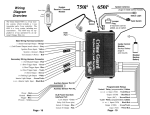
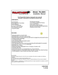
AL-1650-EDPB
AL-1750-EDPB
AL-1850-EDPB
AL-1950-EDPB
AL-2050-EDPB
Deluxe Security & Remote Start System
Installation Guide
July 11, 2012
Temporary cover. Color cover is in a separate file.
Installation Considerations
BEFORE STARTING THE INSTALLATION, READ THIS ENTIRE MANUAL
TO FAMILIARIZE YOURSELF WITH ANY INSTALL REQUIREMENTS
•
•
•
•
•
•
•
BE SURE TO VERIFY EACH CIRCUIT WITH A DIGITAL MULTIMETER
IDENTIFY WHICH CIRCUITS ARE REQUIRED FOR THE VEHICLE IN QUESTION
MOUNT ANY SYSTEM COMPONENTS AND ROUTE WIRING AWAY FROM MOVING PARTS OR PARTS OF THE VEHICLE THAT GENERATE EXCESSIVE HEAT
TAPE OFF OR REMOVE ANY UNUSED WIRING TO PREVENT POSSIBLE SHORT CIRCUITS
ONLY ACTIVATE THE REMOTE START FUNCTION IN A WELL VENTILATED ENVIRONMENT
AFFIX THE UNDERHOOD WARNING STICKER
AVOID ANY AIRBAG CIRCUITS, USUALLY INDICATED BY A YELLOW SLEEVE OR JACKET AROUND THE WIRING
6 Pin Main Wire Harness
Most of the main wiring harness connections are high amperage circuits so high reliability connections must be made. It is recommended to solder and adequately insulate each connection.
Many of these connections are made at the vehicle’s ignition switch so be sure to properly route
the harness away from steering wheel tilt mechanisms or anything that could compromise the wire
insulation. Remember, the goal is for this system to mimic the ignition switch. Keep this in mind
when deciding which ignition & accessory circuits to power. Most, if not all will be required.
Red & Red/White Wires - Constant Power (+) Input
REQUIRED. These wires provide the constant positive 12v power supply for the system’s
operation. CONNECTION: Connect these to a constant +12 volt supply with sufficient amperage
for remote starting. The +12v power supply to the ignition switch is ideal. Some vehicle’s have
low amperage ignition switches in which case you would need to find a power supply at a fuse
block or at the vehicle’s battery. Be sure these wires are fused within 6 inches of the connection
to the vehicle. The two 30AMP fuses in the harness are to protect the system module, NOT THE
VEHICLE. Their use is REQUIRED. It is ideal to have a separate supply for each wire but, if the
chosen supply is sufficient enough, you can combine both the RED & RED/WHITE wires at the
same point.
Pink Wire - Ignition #1 (+) Input/Output
REQUIRED. This connection is required and is critical to the operation of the system. It is
an “IGNITION ON” input when the ignition key is turned on. It is also the primary ignition output
for remote start operation. It turns on when remote start is activated and stays on during engine
cranking for the entire remote start sequence.
CONNECTION: The vehicle’s primary ignition circuit is typically found at the ignition switch. The
proper circuit will show +12v when the ignition key is in the ON/RUN and START positions.
6 Pin Main Wire Harness (cont’d)
Orange Wire - Accessory (+) Output
This circuit is designed to drive accessory circuits like climate control, etc.. It turns on when
remote start is activated (slightly earlier than the primary ignition output) and turns off only during
engine cranking. It will turn back on for the remainder of the remote start sequence.
CONNECTION: An accessory circuit is typically found at the ignition switch. The proper circuit will
show +12v when the ignition key is in the ON/RUN position but not in the START position.
Violet Wire - Start (+) Output
REQUIRED. This output supplies positive voltage to the vehicle’s starter circuit. If using a
starter interrupt circuit for anti-grind, be sure this is connected on the starter side of the interrupt.
CONNECTION: The starter circuit is typically found at the ignition switch. The proper circuit will
show +12v only when the ignition key is in the START position.
Pink/White Wire - Ignition #2 (+) Output - Programmable
This output is programmable to act as an additional ignition, accessory, or start output. It supplies positive voltage for powering any additional circuits required for remote starting the vehicle.
The default operation is as an ignition circuit. See installer feature #8 for options.
CONNECTION: The proper circuit will show +12v only when the ignition key is in the position
of the desired function. See the PINK, ORANGE, or VIOLET wire description for detail on your
desired operation.
18 Pin Secondary Wire Harness
Black Wire - System Ground (-) Input
REQUIRED. This input provides negative ground for all system operations.
CONNECTION: Using a properly sized ring terminal, connect this wire to the vehicle’s chassis.
Using an existing bolt is preferred but make sure that the connection point is clean and free of dirt,
grease, or paint. Bright shiny metal at the connection point is desired.
Orange Wire - Starter Interrupt (-) Output & Relay
This provides 500mA negative ground while the alarm is armed for starter kill and/or during
remote start for anti-grind operation. The operation is selectable with user feature #4.
CONNECTION: This wire is connected to the orange input wire on the included start interrupt
relay socket. Then, locate the vehicle’s (+) starter wire at the ignition switch and cut it. Connect
the starter interrupt relay’s RED wire to the ignition switch side of the cut starter wire. Connect the
starter interrupt relay’s WHITE wire to the starter side of the cut starter wire.
Brown/Red Wire - Brake Pedal (+) Input
REQUIRED. This input is a critical safety circuit which disables the remote start operation
whenever the brake pedal is pressed.
CONNECTION: Connect this to the brake switch wire that shows +12 volts when the brake pedal
is pressed.
Black/White Wire - Neutral Safety (-) Input
REQUIRED. This input is a critical safety circuit which allows remote start operation whenever
the gear selector is in park or neutral (automatic transmission), or when the parking brake is applied (manual transmission). Remote start will not operate unless this wire sees chassis ground.
CONNECTION (Automatic Transmission): Connect this to the neutral safety switch wire that shows (-) ground when the gear selector is in the park and neutral positions.
18 Pin Secondary Wire Harness (cont’d)
CONNECTION (Manual Transmission): Connect this to the brake switch wire that shows (-)
ground when the parking brake is engaged.
Violet/White Wire - Tach Signal Input
This input provides the engine’s RPM signal to the remote start. This is typically the most reliable form of engine detection. To use the tach wire, you must change installer feature #6 to the
tach wire setting.
CONNECTION: This can be connected to any trigger wire for an ignition coil, fuel injector, or the
signal to the tachometer in the dash. Use a digital multimeter set for AC volts to test. The appropriate wire will read between 1-6 volts AC and will increase as the engine RPM increases.
Brown Wire - Siren (+) Output
This output provides a 1 amp positive output to operate the included siren.
CONNECTION: Safely route this wire to the chosen mounting location of the siren and connect it
to the siren’s red wire. Connect the siren’s black wire to chassis ground.
White Wire - Flashing Light (+) Output
This output provides a 10 amp positive output to flash the vehicle’s parking lights (typically). If
the vehicle has a low current negative parking light circuit, use the WHITE/BLACK wire instead.
CONNECTION: Connect this wire to the vehicle’s positive parking light circuit. It will show +12
volts when the parking lights are on. BE SURE NOT TO CONNECT TO THE DIMMER CIRCUIT
WHICH WILL CHANGE VOLTAGE AS YOU TURN THE DIMMER KNOB.
White/Black Wire - Flashing Light (-) Output
This output provides a 250mA negative output to flash the vehicle’s parking lights (typically). If
the vehicle has a positive parking light circuit, use the WHITE wire instead.
CONNECTION: Connect this wire to the vehicle’s negative parking light circuit. It will show ground
when the parking lights are on. BE SURE NOT TO CONNECT TO THE DIMMER CIRCUITWHICH WILL CHANGE RESISTANCE TO GROUND AS YOU TURN THE DIMMER KNOB.
Gray Wire - Hood Trigger (-) Input
REQUIRED. This input is used to detect entry into the hood area of the vehicle. It is also a critical safety circuit that prevents remote start functions while the hood is opened.
CONNECTION: Connect this wire to the vehicle’s existing hood switch or light. It will show ground
when the hood is opened. You can also use the included pin switch and mount it to the radiator
core support.
Green Wire - Door Trigger (-) Input
This input is used to detect entry into the vehicle via any door opening.
CONNECTION: Connect this wire to the vehicle’s existing domelight circuit or door pin circuit. The
circuit will show ground when any door is opened. If you are required to connect to each individual
door pin, diode isolation is required. Use one 1-2 amp diode for each door, facing the diode’s
cathode (stripe) towards the vehicle wiring.
Violet Wire - Door Trigger (+) Input
This input is used to detect entry into the vehicle via any door opening.
CONNECTION: Connect this wire to the vehicle’s existing domelight circuit or door pin circuit.
The circuit will show +12 volts when any door is opened. If you are required to connect to each
individual door pin, diode isolation is required. Use one 1-2 amp diode for each door, facing the
diode’s cathode (stripe) towards the alarm module.
18 Pin Secondary Wire Harness (cont’d)
Red/White Wire - Trunk Release / 2nd Channel (-) Output
This output provides a 250mA negative output when the trunk release/CH2 function is activated
by the controller. The output will remain as long as the controller button(s) is held.
CONNECTION: Connect this wire to the vehicle’s existing trunk release switch if it is a low current
negative circuit. If the circuit is a high current ground or a positive circuit, the use of a relay is required. NOTE: The built-in horn relay circuit can be programmed & utilized for trunk release
if not being used otherwise.
Black/Red Wire - Light Relay N/O (+/-) Input
This circuit provides the constant feed input for the built-in 10 amp domelight relay. Specifically
the normally open pin (pin 87). This relay can be programmed via installer feature #2 for LOCK,
IGNITION, or ACCESSORY if need be.
CONNECTION: Connect this wire to constant power or chassis ground as needed for the chosen
function.
Green/Violet Wire - Light Relay COM Output
This circuit provides the output for the built-in 10 amp domelight relay. Specifically the common
pin (pin 30). This relay can be programmed via installer feature #2 for LOCK, IGNITION, or ACCESSORY if need be.
CONNECTION: Connect this wire to the vehicle circuit chosen to be driven. By default, connect to
the vehicle’s domelight circuit.
White/Red Wire - Light Relay N/C Input
This circuit provides the input for the built-in 10 amp domelight relay. Specifically the normally
closed pin (pin 87a) which is typically only used for polarity reversing circuits. This relay can be
programmed via installer feature #2 for LOCK, IGNITION, or ACCESSORY if need be.
CONNECTION: Connect this wire to constant power or chassis ground as needed for the chosen
function.
Violet/Black Wire - Horn Relay N/O (+/-) Input
This circuit provides the constant feed input for the built-in 20 amp horn relay. Specifically the
normally open pin (pin 87). This relay can be programmed via installer feature #3 for UNLOCK,
TRUNK RELEASE, or PULSE AFTER START if need be.
CONNECTION: Connect this wire to constant power or chassis ground as needed for the chosen
function.
Blue/Black Wire - Horn Relay COM Output
This circuit provides the output for the built-in 20 amp horn relay. Specifically the common pin
(pin 30). This relay can be programmed via installer feature #3 for UNLOCK, TRUNK RELEASE,
or PULSE AFTER START if need be.
CONNECTION: Connect this wire to the vehicle circuit chosen to be driven. By default, connect to
the vehicle’s domelight circuit.
Brown/Black Wire - Horn Relay N/C Input
This circuit provides the input for the built-in 20 amp horn relay. Specifically the normally
closed pin (pin 87a) which is typically only used for polarity reversing circuits. This relay can be
programmed via installer feature #3 for UNLOCK, TRUNK RELEASE, or PULSE AFTER START if
need be.
CONNECTION: Connect this wire to constant power or chassis ground as needed for the chosen
function.
6 Pin Secondary Wire Harness
Pink Wire - 3rd Channel (-) Output
This output provides a 250mA negative output when the CH3 function is activated by the controller. The output will remain as long as the controller button(s) is held.
CONNECTION: Connect this wire to any desired add-on accessory that can utilize a negative
activation input.
White/Blue Wire - Remote Start Activation (-) Input
This input will activate the system’s remote start function when it receives a negative pulse.
Another pulse during remote start operation will turn off the remote start.
CONNECTION: Connect this wire to any device that you desire to activate the remote start feature. It requires a negative pulse input.
White Wire - Alarm Arm (-) Input
This input will arm the system’s alarm when it receives a negative pulse.
CONNECTION: Connect this wire to any device that you desire to arm the alarm. It requires a
negative pulse input.
Brown Wire - Alarm Disarm (-) Input
This input will disarm the system’s alarm when it receives a negative pulse.
CONNECTION: Connect this wire to any device that you desire to disarm the alarm. It requires a
negative pulse input.
Lt. Green/Red Wire - OEM Alarm Arm / CH4 (-) Output
This output provides a 250mA negative pulse when remote start is turned off and when the
system’s alarm is armed. It can be programmed for 4th channel output with installer feature #9.
CONNECTION: Connect this wire to the vehicle’s OEM alarm arm circuit. Typically, it will show
ground when the door cylinder key is turned to the lock position.
Lt. Green/Black Wire - OEM Alarm Disarm / CH5 (-) Output
This output provides a 250mA negative pulse when remote start is activated and when the
system’s alarm is disarmed. It can be programmed for 5th channel output with installer feature #9.
CONNECTION: Connect this wire to the vehicle’s OEM alarm disarm circuit. Typically, it will show
ground when the door cylinder key is turned to the unlock position.
3 Pin Satellite Relay Port (RED)
Green Wire - Start (-) Output
This output provides a 250mA negative pulse when the large VIOLET start wire is active.
CONNECTION: If a negative starter circuit is needed, connect this directly to the vehicle’s negative starter circuit. Otherwise, use a relay (or RS-RP module) to convert this to a high current
circuit.
Red Wire - Constant (+) Output
This output provides a 500mA positive output to drive the positive pin of added relay coils.
Blue Wire - Ignition (-) Output
This provides a 250mA negative output when the large PINK ignition wire is active.
CONNECTION: If a negative ignition circuit is needed, connect this directly to the vehicle’s negative starter circuit. Otherwise, use a relay (or RS-RP module) to convert this to a high current
circuit.
Wiring Overview Diagram
Window-mount Receive / Transmit Module
3rd Chan
Remote Start Activation (-)
Arm Ala
Disarm Alar
OEM Alarm Arm / CH4 (-) Outp
OEM Alarm Disarm / CH5 (-) Output
Status Lights
- OR -
( ( (ECHO) ) )
Valet
Switch
Valet Switch
Status Lights
WIRE LEGEND
Hard wire connection required
Supported via DATA port(s)
BLADE Programming / interafce Module Data
18 PIN HARNESS
Door Trigger (-) Input - GREEN
Tach Input - VIOLET/WHITE
Door Trigger (+) Input - VIOLET
Light Relay N/O (+/-) Input - BLACK/RED
Trunk Release/CH2 (-) Output - RED/WHITE
Light Relay COM Output - GREEN/VIOLET
Starter Interrupt (-) Output - ORANGE
Flashing Light (-) Output - WHITE/BLACK
System Ground (-) Input - BLACK
Brake (+) Input - BROWN/RED
Neutral Safety (-) Input - BLACK/WHITE
Light Relay N/C (+/-) Input - WHITE/RED
Hood Trigger (-) Input - GRAY
Flashing Light (+) Output - WHITE
Siren (+) Output - BROWN
Horn Relay N/C (+/-) Input - BROWN/BLACK
Horn Relay COM Output - BLUE/BLACK
Horn Relay N/O (+/-) Input - VIOLET/BLACK
Interface Module Data
MP
10 A
6 PIN POWE
Constant 12v (+) Input Ignition #2 (+) Output Constant 12v (+)
Start (+) Outp
Ignition #1 (+) Input/Ou
Accessory (+) Outpu
6 PIN AUX HARNESS
3rd Channel (-) Output - PINK
ote Start Activation (-) Input - WHITE/BLUE
Arm Alarm (-) Input - WHITE
Disarm Alarm (-) Input - BROWN
arm Arm / CH4 (-) Output - LT. GREEN/RED
isarm / CH5 (-) Output - LT. GREEN/BLACK
3 PIN SAT. RELAY PORT (RED)
Start (-) Output - GREEN
Constant 12v (+) Output - RED
Ignition (-) Output - BLUE
3 PIN SAT. RELAY PORT (BLUE)
Accessory (-) Output - GREEN
Constant 12v (+) Output - RED
Status (-) Output - BLUE
Valet Switch
Status Light
Antenna
4 PIN DOOR LOCK PORT
Unlock #2 (-) Output - PINK
Unlock #1 (-) Output - BLUE
Constant 12v (+) Output - RED
Lock (-) Output - GREEN
BLADE
Harness Port
BLADE Docking Port
(Bottom of module)
nterafce Module Data Port
nterface Module Data Port
6 PIN POWER HARNESS
nstant 12v (+) Input - RED/WHITE
nition #2 (+) Output - PINK/WHITE
Constant 12v (+) Input - RED
Start (+) Output - VIOLET
gnition #1 (+) Input/Output - PINK
Accessory (+) Output - ORANGE
Backup Battery Port
Slide Bracket For
Backup Battery &
Other Accessories
30 AMP
30 AMP
4 PIN SENSOR PORTS
Constant 12v (+) Output - RED
Ground (-) Output - BLACK
Trigger (-) Input - BLUE
Pre-warn (-) Intput - GREEN
3 Pin Satellite Relay Port (BLUE)
NOTE: There is no dedicated harness included. Use the RED 3-pin harness for this port.
Green Wire - Accessory (-) Output
This provides a 250mA negative output when the large ORANGE accessory wire is active.
CONNECTION: If a negative starter circuit is needed, connect this directly to the vehicle’s negative starter circuit. Otherwise, use a relay (or RS-RP module) to convert this to a high current
circuit.
Red Wire - Constant (+) Output
This output provides a 500mA positive output to drive the positive pin of added relay coils.
Blue Wire - Status (-) Output
This provides a 250mA negative output slightly before and during the large PINK ignition wire’s
operation. This output is programmable. See installer feature #15 for other options.
CONNECTION: This is typically used to activate immobilizer bypass modules. Connect it directly
to the module’s activation input.
4 Pin Door Lock/Unlock Port (RED)
Green Wire - Lock (-) Output
This provides a 0.8 second 250mA negative pulse for any locking operations. The pulse timing
is programmable by installer feature #1.
CONNECTION: Connect this directly to the vehicle’s lock circuit if a negative pulse is required.
Otherwise, a doorlock interface and/or relays are required to convert the output.
Red Wire - Constant (+) Output
This output provides a 500mA positive output to drive the positive pin of added relay coils.
Blue Wire - Unlock #1 (-) Output
This provides a 0.8 second 250mA negative pulse for any unlocking operations. The pulse timing is programmable by installer feature #1.
CONNECTION: Connect this directly to the vehicle’s “all door” unlock circuit if a negative pulse
is required. Otherwise, a doorlock interface and/or relays are required to convert the output. If
you are configuring the system for driver’s priority unlocking, connect this only to the driver’s door
unlock circuit.
Pink Wire - Unlock #2 (-) Output
This provides a 0.8 second 250mA negative pulse for any unlocking operations. The pulse timing is programmable by installer feature #1. This 2nd output is utilized only when you are configuring the system for driver’s priority unlock.
CONNECTION: Connect this directly to the vehicle’s “all door” unlock circuit if a negative pulse is
required. Otherwise, a doorlock interface and/or relays are required to convert the output.
2 Pin Backup Battery Port (WHITE)
This system includes a bracket and harness for utilizing the backup battery option. Thanks to
its innovative design, it only requires a 9 volt battery (can also use the rechargeable
BATPACK-R for a permanent solution). Simply insert the battery into the supplied bracket and
mount the battery pack on the slide bracket next to the backup battery port. Then connect the harness to the battery and module. If using the BATPACK-R, connect its red wire to a fused constant
+12 volt source. When running on backup battery power, the system will only maintain the start
interrupt, siren, door trigger, and hood trigger functions to maintain maximum battery life.
Green Data Port
This port provides a direct digital interface for any Omega IntelliKit, OmegaLink interface module, or other accessories. It can eliminate the need for several wire-to-wire connections. Refer to
the wire diagram overview on page 8 to see which circuits are supported by this port and compare
them to the data functions available from the interface module. This port is also capable of communicating with the standard D2D (Trilogix) protocol and with the ADS (iDataLink) protocol. This
is selectable with installer feature #13. This port also supports a plug-in accessory independently
from the black data port described below. BOTH THE GREEN AND BLACK PORT CAN BE
USED SIMULTANEOUSLY FOR PLUG-IN ACCESSORIES.
Black Data/Programming Port
This port provides a direct digital interface for any OmegaLink interface modules. It can eliminate the need for several wire-to-wire connections. Refer to the wire diagram overview on page 8
to see which circuits are supported by this port and compare them to the data functions available
from the interface module. This port is also capable of communicating with the standard D2D
(Trilogix) protocol and with the ADS (iDataLink) protocol. This is selectable with installer feature
#13.
BLADE OPERATIONS: This port is also used to update the firmware for any BLADE cartridge
used in lieu of a standard interface module. When connected to the OmegaLink OL-LOADER,
this port can also be used to configure all programmable features as well as update the entire
system’s firmware. These functions may require a BLADE cartridge to be installed.
BLADE Cartridge Port
BLADE Cartridge port
On the bottom of the main module, there is a slide door. This door is removed and replaced
with any BLADE cartridge being used. The port is keyed so the cartridge will only insert one way.
Do not use excessive force to install the BLADE, it should snap in with light to moderate pressure.
Also, refer to the install guide for the BLADE firmware being used for further information and
details. When this system detects a BLADE module, the data port protocol will automatic switch to
the ADS protocol. For more info on BLADE modules, visit www.omegaweblink.com.
BLADE Harness Port
When utilizing an OmegaLink BLADE module, this 20 pin connector is used for the harness
that is included with the BLADE module. This allows you to connect directly to the vehicle’s data
bus and other required circuits for the interface.
Dual Zone Sensor Ports (WHITE)
This system is equipped with 2 white dual zone sensor ports. Any Omega single or dual zone
sensor will plug directly into these ports. A dual zone shock sensor is included with this system. If
more than 2 sensors are desired, you can expand a single port with the AU-EXP module. It adds 3
additional sensor ports to the system.
Window Mount Antenna Module
This system is equipped with an outboard receiver or transceiver (2-way) module. It is designed
to be window mounted high on the windshield for optimal performance and range. It is best to
mount this module using the double sided stick pad included (be sure to clean glass before
adhering). Mount it high in the windshield trying to avoid metal parts of the vehicle as they can
create “blind spots” for the antenna. Also, metal based window tint can have an adverse affect on
performance. Since the system’s status lights and valet are contained in this module, high visibility
is also desired for theft deterrence. Route the harness to the antenna module being sure to avoid
sharp metal objects that could compromise the harness jacket.
Status Lights
This system includes 2 status lights that are built into the window mount antenna module. It is
desirable for these to be visible from as many angles around the vehicle as possible for maximum
visual theft deterrence. The control module has a separate port for the status light, so an optional
dash/custom mounted light can be utilized if desired.
Valet / Programming Switch
This system includes a valet switch that is built into the window mount antenna module. The
control module has a separate port for the valet switch, so an optional custom mounted switch can
be used if desired.
Tach Programming
When utilizing the tach wire circuit for engine detection, the vehicle’s tach signal must be programmed to the remote start for proper operation. After making the tach wire connection, perform
the following steps:
Step 1: Turn the ignition key “ON”
Step 2: Within 5 seconds, press the brake pedal 5 times. (the siren will chirp 5 times)
Step 3: Start the engine. The status lights will turn on to indicate it has learned the current tach signal. If it does not light, check your tach connection and start this procedure again.
Step 4: If the engine has a high idle at startup, it may be necessary to allow the idle to “settle” to around 700 RPM. If needed, you can press the valet switch 1 time to resample the tach signal. The status light will flash off then back on once the signal has been resampled.
Step 5: Turn the ignition key “OFF”.
Programming Transmitters
Standard Programming: Using this method to program additional or replacement transmitters
does not turn on or otherwise affect the Unauthorized Transmitter Alert (UTA) feature.
Step 1 Have all transmitters which are to operate the system at hand. Then, turn the ignition “on”.
Step 2 Within 5 seconds of turning on the ignition, press the Valet Switch 5 times. The horn will
briefly sound, confirming that for the next 10 seconds the system is ready to learn a transmitter/
controller code. To enter a code, simply press and release the “lock” button. When the first code
is learned all existing stored codes will be erased.
Step 3 Press the “lock” button on each remaining transmitter one at a time. The system will chirp
the horn once to confirm that each was learned. The transmitter’s other three button’s functions
will automatically be assigned when the “lock” button is learned. If a code is not received within a
10 second period, the learning process will automatically terminate, as indicated by another horn
honk.
If the Unauthorized Transmitter Alert feature is on, programming a transmitter to the
system will activate the “UTA” warning and the extended Status Light indication.
For the next 48 hours, the horn will sound a brief series of chirps every time the
vehicle’s ignition key is turned on.
Special Programming procedure to turn On the UTA feature: Using this method to program
transmitters or optional controllers, and to turn on the Unauthorized Transmitter Alert feature.
Follow the same steps as the Standard Programming, but on any transmitter/controller being
programmed instead of pressing the “lock” button, press the “lock” and the “unlock” buttons
together. This action turns on the Unauthorized Transmitter Alert feature and at the same time
programs the transmitter or controller to operate the system.
Once the Unauthorized Transmitter Alert feature is turned on, the warning will sound for 48
hours after any transmitter programming, including the programming session which was used to
turn it on. This feature can only be turned off again by sending the system back to Omega for a
reset.
Programmable Features
Programming Features
A matrix of all programmable features and their options are on the next page. For detailed information on each feature, please refer to the operation manual. Use the procedure below to make
any necessary changes.
Step 1 Turn the ignition key “ON”, then “OFF”
Step 2 Within 5 seconds of step 1, press the valet switch 5 times to access user features (Press
10 times to access installer features).
~ The siren/horn will sound and the status light will turn on.
Step 3 Within 10 seconds of step 2, press the valet switch the number of times corresponding
with the desired feature’s number.
~ The siren/horn will chirp equal to the selected feature.
Step 4 Change the feature by pressing the transmitter button that corresponds with the desired
setting.
~ The siren/horn will chirp equal to the selected setting.
Step 5 If you wish to change more features, repeat steps 3 & 4 at this time.
Step 6 To exit programming, turn the ignition key “ON” then “OFF”. Or, you can wait 10 seconds
for programming mode to expire.
This device complies with FCC Rules part 15. Operation is subject to the following two conditions, (1) This device may not cause harmful interference and,
(2) This device must accept any interference that may be received, including
interference that may cause undesired operation.
The manufacturer is not responsible for any radio or TV interference caused by
unauthorized modifications to this equipment. Such modifications could void the
user’s authority to operate the equipment.
User Feature Programming: Ignition on, off, press valet 5 times
# Feature
Lock Button
1 Secure Code
1, 0 (default)
2 Last Door Arming
3 Automatic Rearming
”START” button
Unlock button
Trunk button
Off
On w/o lock
On w/ Lock
Off
On w/o lock
On w/ Lock
Enhanced Rearm
4 Starter Interrupt Functions
Alarm
Anti-Grind Only
Alarm+Anti-Grind
Automatic
5 Ignition Override
On
Off
6 Ignition Lock/Unlock
Off
Lock w/ IGN ON
Unlock w/ IGN Off
Lock + Unlock w/
IGN On/Off
7 Open Door Bypass For Ign. Locks
On
Off
8 Confirmation Chirps
On
Except Valet
mode
On Demand
Off
9 Chirp Volume
Low
Med Low
Med Loud
Loud
10 Alarm Cycle
30 sec
60
90
120
11 Flashing Lights Confirmation
On w/ Disarm + On w/ Disarm +
Steady During RS
RS Steady
RS Flashing
12 Disarm Upon Trunk Release
On
Off
13 Arming Delay
3 sec
15
14 Alarm Functions Bypass
On
Off
15 Anti-carjack
Ignition Only
Door Only
16 Open Door Warning Upon Arm
On
Off
17 Remote Start Activation
Start x 2
Start x 1
Lock+Unlock
18 Remote Start Run Time
5 min
10 min
15 min
20 min
Total closure
Flashing During
RS
30
45
Ignition + Door
Off
Installer Feature Programming: Ignition on, off, press valet 10 times
1 Doorlock pulse
0.8 sec
3 sec
Double unlock
2 Light Relay Functions
Dome light
Lock
Ignition
Acc
3 Horn Relay Functions
Horn
Unlock
Trunk Release
Pulse after Start
4 Turbo Timer
Off
1 min
2 min
3 min
5 Manual Transmission
On
Off
Tachless Hi
Tachless Lo
Tach Wire
Datatach
2.25 sec
6 Engine detection
Crank Only (press Lock + Unlock)
7 Crank Time
0.7 sec
1 sec
1.5 sec
8 Pink/White Ignition Wire Function
Ignition
Accessory
Start
9 Arm/Disarm/Additional Ch.
Arm/Disarm
Arm/Ch 5
Ch4/Disarm
Ch 4/Ch 5
10 Gas or Diesel Engine
Gas
Diesel
(15 sec. Delay)
Diesel
(20 sec. Delay)
Diesel
(30 sec. delay)
11 Remote Start Lock control
Off
Lock after start
Unlock before start
Both
12 Low Temp Crank Extender
0ms
200ms
300ms
400ms
13 Data Port Protocol
D2D (Trilogix)
ADS (iData)
14 Lock on prewarn
On
Off
15 Blue Satellite Port Blue Wire Function
Status
Pulse Before
Start
Pulse After Start
Pulse After
Engine Off
16 Low Current/Motorcycle Mode
On
Off
OMEGA REMOTE STARTERS
CAR SECURITY SYSTEM