1
(OIITROEUN
D'ORDNE
ETDEPRESETCT
DEPIIÂSI
PHASE
ROTAIIO]I
TESTER
lloticed'ufilisqtion
User'sMqnuol
E{lriEfitl
o
o
o
FRANçAtS
INDEX
Page
3
........
4
5
6-8
9
10
20
Introduction..
Prescriptions
Oesecuriie...
Caractéristiques...............
Méthode
de mesure....
Spécifications...................
Maintenance
Addresse
et contacts...
ENGLISH
TABLEOFCONTENTS
Description
Ru1es...........
Safety
S a f e tC
yhecks
GeneralDescription...
BriefDescription...............
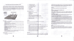
Operating
Instructions..
F r o nPt a n e l L a y o u t . . . . . . . . , .
Principle
of howit w0rk..........
Preparation
foruse.........
F u s eR e p l a c e m e n t . . . . . . . . . . .
Page
11
. . . . . . . . . . . . . . . . .1.2. . . . .
. . . . . . . . . .1. .3.
15
15
16
17
18
. . . . . .1. 8
19
1.
lntroduction
Remarque
cet instrumenta été conçu et testé selon les prescriptionsoe
la norme internationaleIEC publication34g. Safetv
R e q u i r e m e n tfso r E l e c t r o n i cM e a s u r i n gA p p a r a t u s I, E C - i0 1 0
(EN61010).
suivre scrupuleusement
les prescriptionsde sécuritélors de
I'utilisation.
ATTENTION
Lire les prescriptions de sécurité avant toute
utilisation
Prescriptions
de sécurité
2,
.
avanttouteutilisation
de I'appareil.
Lirecesprescriptions
.
quedansleslimites
spécifiées.
Endehors
des
N'utiliser
I'appareil
pounait
l'appareil
êtreendommagé
et la sécurité
de
limites,
I'utilisateur
nonqarantie.
.
vérilerle bonétatdescordons
de mesure
Avanttouteutitilation,
(absence
les
Dansle cascontraire,
remplacer
de craquelure).
cor00ns.
. Toujours
identiques
desfusibles
de caractéristiques
à celles
utiliser
la tension
de service
et le pouvoir
de coupure.
en particulier
spécifiées,
.
Conditionsd'utilisation:
(1)
à l'intérieur
Utilisation
(2)
: 600V- CATlll
d'installation
Catégorie
(3). Degréde pollution
:2
(4). Altitude
: 2000mètresmaximum
d'utilisation
(5). Humidité
relative
: 80%Max.
(6)
: 0'C - +55oC.
Température
d'utilisation
(7). Température
: -20"C- +70"C.
de stockage
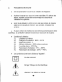
.
:
sontutilisés
surI'appareil
Lessymboles
suivant
I r-t
I
Double
isolement
l-l
A
/-t
/l\
/'\
! Risque
Danger
dechocélectrique
\
Attention
! Seréférer
aumanuel
-4-
3.
Caractéristiques
.
L'appareil
inclusle testde présence
de phaseet le sensde rotation
desphases
r
Cetappareil
estI'outil
idéalpourI'installation
de dispositifs
électrique
ouélectrotechnioue.
.
pasd'alimentation
Autonome,
il ne nécessite
.
Conforme
à la normeIEC1010
o
Livréaveckitde connexion
de sécurité
o
Protection
: parfusibles
(2fusibles
internes
F500mA
/ 250VHPC5 x 20mm)
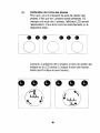
Utilisation
L'indicationde présenceet de rotationse fait par un afficheur
LCDà fort contraste.Dansla partiehaute,on trouveles
indications
de présence,
dansla partiecentrale,
on trouve
I'indication
du sensde rotation.
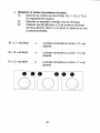
Indicators de
Présence de Phase
Utilisation
entesteur
deprésence
dephase:
(1) Brancher
lescordons
surtesentrées
R(l1)-S(12)-T(13)
Enrespectant
lescouteurs
(2) Brancher
(source
audispositif
à contrôler
d,éneroie)
(3) S'assurer
quelesafficheurs
LCDdeprésence
Oàoi,ase
sonttousallumés.
Sinon,
il y a rupture
ouabsence
surune
ouplusieurs
phases.
Sil( L1r estéteint
Laphaseconnectée
au cordon< R r est
absente
Si ( L2 > estéteint
Laphaseconnectée
au cordon< S > est
absente
Si ( L3 > estéteint
La phaseconnectée
au cordon< T > est
absente
ffiHm
(4)
Vérificationde I'ordredes phases
Pourqu'ily aituneindication
de sensde rotation
des
phases,
il fautqueles3 phases
soientprésentes.
S'il
manque
uneseuledes3 phases,
I'afficheur
LCDcentral
resteraéteint.ll fautalorsrevoirlesbranchements
ou le
disoositif
à tester.
../"--'\
ir-
--
";
y a présence
Lorsqu'il
des3 phases,
le sensde rotation
est
(L indique
indiqué
surle LCDcentral
le sensantihoraire,
tandisqueR indique
le senshoraire).
G
,"'î\
l-
LLL,i
\_ --t
a
f;)
\.-*JF
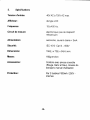
5.
Spécifications
Tensiond'entrée:
40VACà 700VACmax
Afficheur:
detypeLCD
Fréquence:
'15 400
à
Hz
Circuitde mesure:
(pasdedispositif
électronique
mécanique)
Alimentation:
< 3mA
autonome,
courant
drainé
Sécurité:
I E C - 1 0 1C0a tl l l ,- 6 0 0 V
Dimensions:
150(L)
x 72(l)x 34(H)mm.
Masse:
'1609
environ
Accessoires:
Cordons
avecpincescrocodile
(Rouge,
blancet bleu),Housse
de
transport,
manuel
d'utilisation
Protection
:
Par2 fusibles
F500mA
/ 250Vinternes
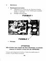
Maintenance
.
Remplacement
desfusibles
(l).
Débrancher
lescordonsde test.Dévisserle fond le
boîtieret remplacerle ou les fusiblespar un modèle
F500mA/ 250VHPC
(2). Revisser
le fondde boîtier.
F U S I B L E1
FUSIBLE
o
Nettoyage:
ATTENTION
Afin d'éviter tout risque de choc électrique, ne jamais
exposer le boîtier à I'eau lors de I'utilisation
Ncttoyerpériodiquement
le boîtierà I'aided'un chiffon doux et
humide.Ne pasutiliserde solvant
-{o-
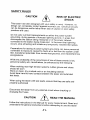
SAFETYRULES
CAUTION
RISKOF ELECTRIC
SHOCK
This testerhas been designedwith your safetyin mind. However,
no
designcan completelyprotectagainstincorrectuse. Electrical
circuits
can be dangerousand/orlethalwhen lackof cautionor poor
safetv
practicesare used.
Do not carryout field measurements
on eitherthe powersystem
grounding,duringperiodsof forecastlightningactivity,
in aieas that
encompassthe stationbeingmeasuredor of the powernetwork
connectedto the stationbeingmeasured.In the eventthat lightning
occurs,stop ail testingand isorateany temporariry
instailedte"stspi[es.
Preparations
for testingof powersystemgroundingcan reavepersonnel
vulnerableto exposurecausedby faurtsal or fed fôm tne syiiem
unoer
test,transferredpotentiars
from remotetest grounds,and inâdvertentrine
energisations.
while the.probabilityof the occurrenceof one of theseevents
is low,
personnersafetywiil, nevertheress,
be enhancedby the foilowiÀg.
When.workingnear hightensionsystemsrubbergtovesand
shoes
shouldbe worn.
Work.onclean,dry crushedrock or an insulatingblanket.
Avoid bare hand to hand contactbetweenthe tetter and extended
test leads.
when usingthe testerwith test reads,ensurethat they are safe
and
properlyauthorized
Disconnectthe testerfrom any externarcircuitwhen checking
or
changingthe Fuses.
/\
CAUTION /I\
READTHEMANUAL
1.\
Followtheinstructions
in theManuar
foreverymeasurement.
Readand
understand
thegenerar
instructions
beforeatiempting
to usethisiester
-11-
SAFEW CHECK
trretester check the conditionof the test leads and the
Before
"singis done by usinga proovingunit'
fuses. This
The test leads must be free of cracks or any damagesand must be
insulatedas when theYwere new.
Fuse replacementis describedlaterin this user'smanual"
When changingthe fusesby removingthe coverto accessthe internal
circuitry,alwaysdisconnectthe test leads'
When replacingthe fuse use only the type specified,HBC fuse' and
insertcorrectlyinto the fuse holder.
Always double check the lead connectionsbefore making
.eaiur"m"nts. This instrumentshas 2 internalfuses' For increased
safety,use fused test leads (optional).
DON'TTOUCH
or other"Live"parts
Dorittouchexposedwiring,connections
of an electricalcircuit.lf in doubt,checkthe circuitfirstfor
voltagebeforetouchingit.
Do not usecrackedof brokentestleads'
SHOULDONLYBE USEDBY A
THISINSTRUMENT
COMPETENTSUITABLYTRAINEDPERSON.
REMEMBER
A
A
SAFETYIS NO ACCIDENT
SHOCK
CAUTIONRISKOF ELECTRIC
CAUTIONREADTHE MANUAL
-12-
GENERALDESCRIPTION
This TestInstrumentis a 3 Phases presence and Rotation Indicator
whichdisplaythe resultson a large ,,highcontrast', Liquid Crystat
Display.
It does not need any battery as it derives it's power from the system
under test.
It can be utilizedon a 3 Phase powered System (thesupplyside)
withouthavingto worryaboutdamageto the tester.Furthermore,
it has
internal fuses, so non fusedtest leadscan be utilized.
when utilizedon a 3 PhasePoweredsystem,the instrumentis then
utilizedas a 3 Phases PresenceIndicator.
oGa
."^4
when utilizedon a 3 PhasePoweredsystem,the instrumentis also
utilizedas a 3 Phases Rotation Indicator.
when utilizedon a 3 Phases powered System,this instrumentis a rotary
field indicationinstrumentwhichdisplayall three phasesby showingup
it's corresponding
LCD PhasepresenceIndicators(L,, L, ând L.). "
It displaythe rotation(clockwiseor anti-clockwise)
on the LCD.
1-6-9 r=6-q
.'â
"',
tt"J'
,i
R',
*+i'
',*ài
I {.7
li
l
-:,:llfiïff i:ïi,. {
;ïJ,îËïî,
3":,:ff
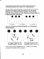
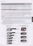
This instrument representsthe quickest and Easiestway for
verifying the presenceand rotation of a 3 Phase System.
You can, beforeconnectingSupplyto Load,and from the supplyside;
Quickly and easily verify the presence of the three
Phases on a 3 Phases Power System. The LCD will
indicate the presence of each respective Phase with it's
Phase presence indicators.
oo
-j
,i
Ll Mrssing
No Rotâtion lndication
L2 Missing
No Rotation Rotation lndication
a
r:-.i
L3 Mrssing
No Rotation Rotation Indicatron
You can confirm the Phase Rotation on a Powered 3
Phase System.
3 Phases Presence OK
R o t a t i n gR i g h t L 1 L 2 L 3
3 Phases Presence OK
R o t a t i n gL E F T L 2 L 1 L 3
The correspondingArrows and L,, L, and L.will clearly
indicatethe rotationof the phases.
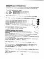
PRoPUcrpESCRtPfl
oN
PFIFE,
This 3 Phasespresenceano Rotâtiontnoicator
has 3 test readswhicn
connectsto the 4 mm femalesocketson the tester,
on the one siOe.
TheseTestleadsare colorcoded.
L1 = Red
whichconnectsto L1 on the tester.
L2 = White whichconnectsto L2 on the tÀster.
L3 = Blue whichconnectsto L3 on the tester
On the otherside of the test leadsare the probes.
atsocolorcoded.
,o
The testerhas three individuars
LCD phase presenceIndicators
L C D f o r I n d i v i d u apl h a s ep r e s e n c eI n d i c a t i o n =
L1
LCD for Individualphase presencelnOtcàiiàn =
L2
L C D f o r I n d i v i d u apl h a s ep r e s e n c efn O i c a i i o n =
L3
Pleasenote that any of theseLCD fnOiiàiàË
wiil ontystart
To tishtup if more tÉan80Vacb
t,";;;i;ùà"n
2 phases.
"ny
,-+R
to
disptay
ctockwise
rotary
direction.
> L,Ll.
I!r" !ç?
The LCD to displaycounterclockwise.
,Q
'Q
,
\l
gqER4ilNG |NSTRUCilONS
.
(
t
Determinationof the rotary field direction
^
and phase
,/.",..
presence
.
L)r
.,
Ol S PhaseSystem,the
sequenceof the 3 phasesdeterminethe=
?
rotationof a 3 phasemotorconnectedto tÀat
system.
The correct3 phase SequenceL,, L., L, results
in a clockwiserotationof
the connectedmotor.
connectthe TestLeadsto the socketsof the Instrument,
respectingthe
correctcolor.Red to L,, Whiteto Lr, Blue to L,.
Clip the test probesto the poweredthreemainspnases,
L,, L,, L,
When connectingto a voltagesuperiorto 40V AC,
the correspondinq
LCD Indicatorwi' show,,ingiqt[b tne presànce
corresponding
lead (1,, 1,, L, LCD).
"rinË "Ëriàs;;ii::
lf the LCD (Rightarrows)L,-Lr-L. is iiluminated,
crockwiserotaryfierdis
present.
lf the LCD(Leftarrows)L.-L2-L,is illuminated,
a counterclockwiserotary
fieldis present.
-15-
I
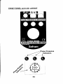
FRONT PANEL and LGD LAYOUT
',/ z
/J
oaa
Phase Presence
,lndicators
PRINCIPLEOF HOW IT WORK
As this instrumenttakes it's power from the
circuitunder test,
it has a power supprycircuitwhich derive it's power
rrôm tne
:y:tqr That supply circuit regutatea +SV tol tne circuitry.
This is why you need a minimumof 40Vac
beforetniiinstrumentis operational.
The first circuit is the 3 phase presence indicator,
which is
shown by the individuarphase presenceLCD
Indicatorsand
the second circuitis the three phase seguence
indicatorby
LCD indication.
3 Phase PresenceIndicationcircuit:
The voltagemeasuredbetweenphasesis
utilizedto triqqer
the,co'espo.ndingphase presence LCD in;l;;til.
o;".Ë
that voltageis high enough,it's presenceis
shown on tÀ"
LCD Indicator.
3 Phase sequence indicatorcircuit.
T-hesequence of these measured vortages
are feed into a
digital circuitwhich compare which phase sequence
to
indicateand indicateit on the LCD.
An oscillatorcrock the LCD to increase it's rife
duration.
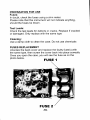
PREPARATIONFOR USE
Fuses:
In doubt,check the fuses using a ohm meter.
Pleasenote that this instrumentwill not indicateanything,
shouldthe fuses be blown.
Test Leads:
Check the test leads for defects or cracks. Replace if cracked
or damaged.Only replacewith the same type
Cleaning:
Use a damp cloth to clean the case. Do not use chemicals
FUSES REPLAGEMENT
Unscrewthe back cover and replacethe faultyfuse(s)with
the same type, then screw the cover back into place correctly
Once you open the case, you will see the fuse as on the
photo below.
I
FUSE
-18-
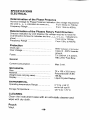
SPECIFICATIONS
ELECTRICAL
Determination of the phase presence
Nominar
Vortage
forphasepresence
lndication
(thevortage
required
for
theLCDL', L,,L. indicators
to comeon)...
From40Vàcto 7ôoù".
Frequency
Range
Froml SHzto 40OHz.
Protection
Overload......
Over Voltage
600V lUetween
alllerminals)
Classllt - G00Vt;;;rd;
groun0.
2X500mA,5X20mm
H B C , 2 5 0 VF a s tB t o w
General
CurrenC
t o n s u m p t i o.n. . . . .
Max 3 mA.
..
ENVIRONMENTAL
O p e r a t i n tge m p e r a t u rR
e ange:.........
7 2 x 1 5 0x 3 3 . 8( m m )
Polycarbonate/A BS
158.59
LiquidCrystatDisptay
0'C to + 55 .C
n o t i n f u l ls u n ! ! ! !
-20 "C to + 70 .C
CLEANING
clean the instrumentcase with an anti-staticcreaner
and
wipe with dry cloth.
Pouch
Vinyl.
-19-
SEFRAM Instruments et Systèmes
32, Rue Edouard MARTEL BP55
F42009- SAINT-ETIENNECedex 2 / FRANCE
Tel : 0825 56 50 50 (o,tserrcrmn)
F a x : + 3 3 ( 0 1 4 7 75 7 2 3 2 3
Site WEB : www.sefram.fr
e-mail : [email protected]
Référence
: M908200F00