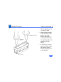
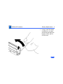
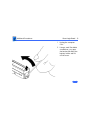
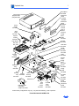
1
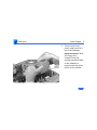
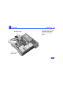
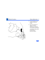
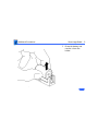
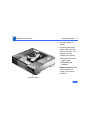
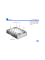
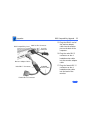
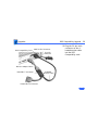
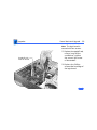
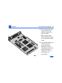
K Service Source
Power Macintosh 6100/
WS 6150
Power Macintosh 6100/60, 6100/60AV, 6100/66,
6100/66AV, 6100/DOS Compatible, and
Workgroup Server 6150
K Service Source
Basics
Power Macintosh 6100/WS 6150
Basics
Power Macintosh System Overview - 1
Power Macintosh System Overview
PowerPC microprocessors are a family of processors built
on reduced instruction-set computing (RISC) technology.
RISC processors streamline the internal workings of
computers. Whereas traditional (complex instruction-set
computing, or CISC) processors contain a wide variety of
instructions to handle many different tasks, RISC
processors contain only those instructions that are used
most often. When a complex instruction is needed, a RISC
processor builds it from a combination of basic instructions.
RISC processors are designed to execute these basic
instructions extremely quickly. The performance gains
achieved by speeding up the most-used instructions more
than compensate for the time spent creating less-used
instructions.
Basics
Power Macintosh System Overview - 2
Previously, RISC technology had been used only in high-end
workstations and commercial database servers. With the
introduction of Macintosh PowerPC computers, Apple
succeeded in bringing RISC technology to personal
computing.
Key Points
Three key points to remember about a PowerPC processorbased Macintosh system: It's a Macintosh; it's compatible; it
offers tremendous performance.
Apple's PowerPC computers feature the same user interface
as their 680x0-based predecessors. Users can mix RISCbased and 680x0-based Macintosh systems on the same network and exchange files and disks between them. In addition,
users can run both 680x0 and native PowerPC applications
on the same Power Macintosh system simultaneously.
Basics
Power Macintosh System Overview - 3
Compatibility is not limited just to applications. INITs,
CDEVs, drivers, and other Macintosh utility software also
work on PowerPC processor-based Macintosh systems. So do
AppleTalk devices (such as printers), SCSI devices (such as
hard drives and scanners), ADB devices (such as mice,
trackballs, and keyboards), and other Macintosh cards and
peripherals.
The primary operating system for PowerPC processorbased Macintosh computers is System 7. The operating
system has been optimized for the highest performance on
the PowerPC processor. This optimization of System 7
benefits applications written for 680x0 systems as well as
those developed specifically for PowerPC processor-based
systems.
And while PowerPC-based Macintosh systems running
native applications offer two to four times the performance
Basics
Power Macintosh System Overview - 4
of the fastest 68040- and 80486-based personal
computers, the real promise of PowerPC technology is that
it enables Apple and other developers to deliver new
software capabilities on Macintosh systems that were
previously available only on high-end workstations.
Troubleshooting Tips
When troubleshooting Power Macintosh systems, keep in
mind the following:
1
2
If a Power Macintosh system does not power up, you
should first attempt to reset the logic board. Instructions are provided in the Additional Procedures chapter.
With Power Macintosh computers, you must install
noncomposite RAM SIMMs only, and the RAM SIMMs
must be installed in like pairs (that is, the same size and
speed). Additional troubleshooting information is
Basics
Power Macintosh System Overview - 5
3
4
provided in the Symptom Charts section of the
Troubleshooting chapter under the “System” topic
heading.
If a Power Macintosh system has bad RAM SIMMs
installed, you will not hear death chimes. Instead, a
dialog box will appear alerting you to the fact that a bad
RAM SIMM has been detected. Additional troubleshooting
information is provided in the Symptom Charts section
of the Troubleshooting chapter under the “System” topic
heading.
If the system hangs shortly after installing a new NuBus
card, contact the vendor to verify that the card is
compatible with the Power Macintosh system or to see if
there is a software upgrade available. If the NuBus card
is an Apple manufactured product, refer to the Service
Tech Info Library for more information.
Basics
Power Macintosh System Overview - 6
5
The Power Macintosh AV systems use the same logic
board as the non-AV versions. The only difference is that
the AV versions have the Power Macintosh AV Card
installed in the PDS slot.
The Power Macintosh 7100/66 and 8100/80 systems
must have a video card installed in the PDS slot. The
Power Macintosh 7100/66 system uses the Power
Macintosh 2 MB Video Card and the Power Macintosh
8100/80 system uses the Power Macintosh 4 MB Video
Card. A missing card can result in a system that won't
boot or a system that crashes.
Basics
HDI-45 Pinouts - 7
HDI-45 Pinouts
This section includes an illustration of the HDI-45
connector and a table containing the pinout descriptions.
Figure: HDI-45 Connector on the Logic Board
Basics
HDI-45 Pinouts - 8
Table: HDI-45 Pinouts
Pin
Description
1
Analog audio ground
3
Left channel audio input
2
4
5
6
7
8
9
Audio input shield
Right channel audio input
Left channel audio output
Right channel audio output
Reserved
Monitor ID sense line 1
Monitor ID sense line 2
(continued)
Basics
HDI-45 Pinouts - 9
Pin
Description
10
Green ground (shield)
12
Video input power ground
11
13
14
15
16
17
18
19
20
Green video output (75Ω)
Power for camera +5 V
Reserved
Reserved
Reserved
Reserved
Monitor ID sense line 3
S-video input shield
S-video input luminance (Y)
(continued)
Basics
HDI-45 Pinouts - 10
Pin
Description
21
S-video input chroma (C)
23
Reserved
22
24
25
26
27
28
29
30
31
Reserved
Reserved
Reserved
Red ground (shield)
Red video output (75Ω)
I 2C data signal
I 2C clock signal
Reserved
Monitor ID
(continued)
Basics
HDI-45 Pinouts - 11
Pin
Description
32
Monitor ID
33
Vertical sync signal
35
ADB power +5 V
34
36
37
38
39
40
41
42
Composite sync signal
ADB ground
ADB data
Keyboard switch
Reserved
Reserved
Monitor ID
Horizontal sync signal
(continued)
Basics
HDI-45 Pinouts - 12
Pin
Description
43
Video sync ground
45
Blue video output (75Ω)
44
Blue ground (shield)
Basics
Rear Panel Connectors - 13
Rear Panel Connectors
The figure on the following page shows the rear panel of a
Power Macintosh 6100/60AV computer. The Workgroup
Server and other non-AV versions of this machine would not
include the S-Video In, DB-15 Video, and S-Video Out ports,
which are actually part of the AV Card.
Basics
Rear Panel Connectors - 14
S-Video In
Ethernet SCSI
HDI-45
Video
DB-15
Video
S-Video Out
Reset/
Interrupt
Sound In
Sound Out
ADB
Modem
Printer
Power Macintosh 6100/60 AV Rear Panel
Basics
Logic Board Connectors - 15
Logic Board Connectors
The figure on the following page shows a Power Macintosh
6100 Series logic board.
Basics
Sound Out
Sound In
Logic Board Connectors - 16
Serial Ports
ADB
AV Display
Connector SCSI
Ethernet
DRAM
SIMMs
601
PDS
ROM
Cache 601
Chip
Soldered
DRAM
Basics
Apple RAID Software - 17
Apple RAID Software
Apple RAID (Redundant Array of Independent Disks)
software protects data from loss during a disk failure and
enhances the speed of data storage and retrieval. It is
available for all Power Macintosh Workgroup servers.
Data protection is achieved through disk mirroring, a data
storage scheme in which identical data is stored on two
different disks. Apple RAID can also be configured for disk
striping, a data storage scheme in which successive units of
data are transferred to several disks at one time.
If you plan to install the Apple RAID software on an existing
Power Macintosh Workgroup Server, or if you are
reinitializing an existing Apple RAID drive, keep in the mind
the following:
Basics
Apple RAID Software - 18
• If you wish to use your server's startup disk for Apple
RAID, do not install the Apple RAID program on your
startup disk until you have initialized and set up new
volumes on that disk. Before you initialize the startup
disk, back up all valuable data.
• You must reinitialize all disks on which you will use
Apple RAID volumes. Initializing with Apple RAID
removes all data, so be sure to back up your disks first.
• Apple HD SC Setup does not recognize Apple RAID
volumes. If you want to remove or resize volumes on
Apple RAID disks, use the Apple RAID program.
• The Apple RAID CD contains the facilities to reinstall
your system software. However, if you have made any
customizations to your system files, such as adding
extension files, control panels, or preference files, then
Basics
Apple RAID Software - 19
back up your system files now. Back them up in such a
way that you can restore your system files separately
from the nonsystem files on your disk. You will later
restore your system files using the backup copy rather
than the System Installer on the RAID CD, so that you
preserve your system customizations.
K Service Source
Specifications
Power Macintosh 6100/WS 6150
Specifications
Processor - 1
Processor
CPU
6100/60 & 6150:
6100/66 & 6150/66:
60 MHz PowerPC 601 RISC microprocessor
Built-in MMU and FPU
32K of on-chip cache memory
Requires system software version 7.1.2 or later
66 MHz PowerPC 601 RISC microprocessor
Built-in MMU and FPU
32K of on-chip cache memory
Requires system software version 7.5 or later
Specifications
Memory - 2
Memory
RAM
6100/60 & 6150:
6150/66:
8 MB RAM soldered on board; expandable to 72 MB via 2 SIMM
sockets on logic board (requires a pair of same size, 80 ns or
faster, 72-pin, noncomposite SIMMs); 16 MB configuration
has two 4 MB SIMMs installed
16 MB RAM standard (8 MB soldered on board and two 4 MB
SIMMs); expandable to 72 MB via 2 SIMM sockets on logic
board (requires a pair of same size, 80 ns or faster, 72-pin,
noncomposite SIMMs)
Note: SIMMs must be installed in pairs of the same size and
speed. Install noncomposite SIMMS only.
Specifications
ROM
Memory - 3
4 MB installed on SIMM socket
VRAM
6100/60, 6100/66,
6150 & 6150/66:
None
6100/60AV & 6100/
66AV:
2 MB on Power Macintosh AV Card
Cache
6100/60 & 6150:
32K of on-chip cache; optional 256K level 2 cache available
6100/66:
32K of on-chip cache; 256K level 2 cache standard
Clock/Calendar
CMOS custom chip with long-life lithium battery
Specifications
Disk Storage - 4
Disk Storage
Floppy Drive
1.4 MB Apple SuperDrive Manual Insert
Hard Drive
6100/60:
160 MB or 250 MB hard drive
6100/66:
350 MB or 500 MB hard drive
6150/66:
700 MB hard drive
Specifications
Disk Storage - 5
CD-ROM Drive
6100/60:
Optional internal CD-ROM drive
6100/60AV:
Internal AppleCD 300 Plus CD-ROM drive
6100/66 & 6100/
66AV:
Internal AppleCD 300 Plus CD-ROM drive standard on some
models and optional on others
6150/66:
Internal AppleCD 600 CD-ROM drive standard
Specifications
I/O Interfaces - 6
I/O Interfaces
SCSI
Serial
Apple Desktop Bus
One SCSI port; DB-25 connector
Supports a maximum of six external SCSI devices (five when CDROM is installed)
Two RS-232/RS-422 LocalTalk/GeoPort serial ports; mini DIN9 connectors (backward compatible with mini DIN-8
connectors)
One Apple Desktop Bus (ADB) port; mini DIN-4 connector
Maximum power draw 500 mA; maximum of three devices total
Specifications
I/O Interfaces - 7
Expansion Slot
6100/60, 6100/66,
6150 & 6150/66:
Internal expansion slot supports either a processor-direct slot
card or 7-in. NuBus card (with appropriate adapter)
6100/60AV & 6100/
66AV:
Units ship with Power Macintosh AV card installed in the internal
expansion slot
Ethernet
Sound
One built-in AUUI-15 Ethernet port
16-bit stereo in and out
Sample rates of 48, 44.1, 24, and 22.05 kHz
Input/output line level: 1 V peak-to-peak
Input/output signal-to-noise ratio (SNR): 82 dB with no audible
discrete tones
Specifications
Sound (continued)
I/O Interfaces - 8
Bandwidth: 20 Hz–20 kHz (± 2 dB) at 44.100 kHz sample rate
THD+N (total harmonic distortion plus noise): less than 0.05%,
measured 20Hz–20kHz with a 1-Vrms sine wave input
Video
6100/60, 6100/66,
6150 & 6150/66:
One HDI-45 DRAM-based video port on logic board supports
direct connection to Apple AudioVision monitors; and, with
HDI-45 to DB-15 adapter (which is included), these
computers support 12", 13", 14", 15" portrait, 16", and 17"
monitors
Specifications
I/O Interfaces - 9
Video (continued)
6100/60AV & 6100/
66AV:
One HDI-45 DRAM-based video port on logic board supports
direct connection to Apple AudioVision monitors; and, with
HDI-45 to DB-15 adapter (which is included), these
computers support 12", 13", 14", 15" portrait, 16", and 17"
monitors; Power Macintosh AV card provides: DB-15 VRAMbased video port that supports 12", 13", 14", 15" portrait,
16", 17", 20", and 21" monitors; one S-video/composite
input and one S-video/composite output port.
Note: Only one monitor can be attached to the AV card at one
time (that is, either through the DB-15 port or the S-video
port).
Specifications
I/O Devices - 10
I/O Devices
Keyboard
Standard, extended, or adjustable keyboard
Keyboard draws 25–80 mA, depending on model of keyboard
Mouse
ADB Mouse II; Draws up to 10 mA
Microphone
6100/60, 6150 & 6150/
66:
6100/60AV, 6100/66
& 6100/66AV:
Optional Apple PlainTalk microphone; unidirectional and
optimized for use with speech recognition
Apple PlainTalk microphone standard
Specifications
Video Display - 11
Video Display
Video Display
All Power Macintosh 6100 series computers support
monochrome, color, VGA, and SVGA formats on the HDI-45
connector, including:
•
•
•
•
•
•
•
Macintosh 12" Monochrome Display (640 x 480)
Macintosh 12" RGB Display (512 x 384)
AppleColor High-Res RGB 14" Monitor (640 x 480)
Apple AudioVision 14 Display (640 x 480)
Macintosh Color Display (640 x 480)
Macintosh 15" Portrait Display (640 x 870)
Macintosh 16" Color Display (832 x 624)
Specifications
Video Display
(continued)
Video Display - 12
In addition, the AV versions support (via the DB-15 connector)
•
•
•
•
•
Macintosh 19" Color Display (1024 x 768)
Apple Multiple Scan 20 Display (1152 x 870)
Macintosh 21" Color Display (1152 x 870)
NTSC (512 x 384 and 640 x 480)
PAL (640 x 480 and 768 x 576)
Specifications
Electrical - 13
Electrical
A/C Line Input
Voltage
Input Line
Frequency
Input Power
Power Supply DC
Output
100–240 VAC; RMS single phase, automatically configured
50–60 Hz
132 W maximum continuous, 201 W peak input (not including
monitor power)
86 W continuous output
Specifications
Physical - 14
Physical
Dimensions
Weight
Height: 3.4 in. (85 mm)
Width: 16.3 in. (415 mm)
Depth: 15.6 in. (399 mm)
14.0 lb. (6.4 kg), weight varies depending on internal devices
installed
Specifications
Environmental - 15
Environmental
Operating
Temperature
Storage
Temperature
10–40° C (50–104° F)
–40 to 47° C (–40 F to 116.6° F)
Relative Humidity
5–95% (noncondensing)
Altitude
0–3,048 m (0–10,000 ft.)
K Service Source
Troubleshooting
Power Macintosh 6100/WS 6150
Troubleshooting
General - 1
General
The Symptom Charts included in this chapter will help you
diagnose specific symptoms related to your product. Because cures
are listed on the charts in the order of most likely solution, try
the first cure first. Verify whether or not the product continues to
exhibit the symptom. If the symptom persists, try the next cure.
(Note: If you have replaced a module, reinstall the original module
before you proceed to the next cure.)
If you are not sure what the problem is, or if the Symptom Charts
do not resolve the problem, refer to the Flowchart for the product
family.
For additional assistance, contact Apple Technical Support.
Troubleshooting
Symptom Charts/Power Supply - 2
Symptom Charts
Power Supply
System does not
power up
1
2
3
4
Reset logic board. (Refer to Additional Procedures.)
Reseat ROM SIMM and cache SIMM.
Replace power supply.
Replace logic board.
Troubleshooting
Symptom Charts/System - 3
System
System
intermittently
crashes or hangs
1
2
3
4
5
6
7
8
9
Verify that system software is version 7.1.2 or later
(6100/60 & 6150) or 7.5 or later (6100/66 &
6150/66).
Verify SIMMs are noncomposite and installed in like pairs
(same size/speed).
Verify that software is known-good.
Verify that software is Power Macintosh compatible (contact
developer).
Clear parameter RAM. Hold down <Command> <Option> <P>
<R> during startup but before “Welcome to Macintosh”
appears.
Replace cache SIMM (if installed).
Replace DRAM SIMMs. Refer to Memory manual.
Replace logic board. Retain SIMMs.
Replace power supply.
Troubleshooting
Symptom Charts/Video - 4
Video
Screen is dark, audio
and at least one drive
operate, fan is
running, and LED is
lit
1
2
3
4
Adjust brightness on monitor.
Replace video cable.
Replace monitor. Refer to appropriate monitor manual to
troubleshoot defective monitor.
Replace logic board. Retain customer’s SIMMs.
Screen is dark, audio
and drive do not
operate, fan is
running, and LED is
lit
1
2
3
4
5
6
Reset logic board. (Refer to Additional Procedures.)
Reseat ROM SIMM and cache SIMM.
Remove peripherals.
Replace DRAM SIMMs.
Replace power supply.
Replace logic board.
Troubleshooting
Symptom Charts/Video (Continued) - 5
Video (Continued)
Partial or whole
screen is bright and
audio is present, but
no video information
is visible
1
2
3
Replace video cable.
Replace monitor. Refer to appropriate monitor manual to
troubleshoot defective monitor.
Replace logic board. Retain customer’s SIMMs.
Screen is completely
dark, fan is not
running, and LED is
not lit
1
2
3
4
Verify that external power cables are properly connected.
Remove peripherals.
Replace power supply.
Replace logic board. Retain customer’s SIMMs.
Troubleshooting
Symptom Charts/Video (Continued) - 6
Video (Continued)
Multiple Scan
monitor attached to
Power Macintosh
6100/60AV displays
ghosting or video
smearing
Replace Power Macintosh AV Card.
Troubleshooting
Symptom Charts/Floppy Drive - 7
Floppy Drive
Audio and video are
present, but internal
floppy drive does not
operate
1
2
3
Replace internal floppy drive cable.
Replace internal floppy drive.
Replace logic board. Retain customer’s SIMMs.
Floppy disk ejects,
and display shows Mac
icon with blinking
“X”
1
2
3
4
Try a different floppy disk.
Replace floppy drive cable.
Replace internal floppy drive.
Replace logic board. Retain customer’s SIMMs.
Floppy disk does not
eject
1
Switch off system and hold mouse button down while
switching on the system
Eject disk manually.
Replace floppy drive cable.
Replace floppy drive.
2
3
4
Troubleshooting
Symptom Charts/Floppy Drive (Continued) - 8
Floppy Drive (Continued)
Floppy drive
attempts to eject disk
but doesn’t
1
2
3
4
Push floppy disk completely in.
Eject floppy disk manually.
Replace floppy drive.
Reseat or replace top housing assembly.
Troubleshooting
Symptom Charts/Hard Drive - 9
Hard Drive
Internal hard drive
runs continuously
1
2
3
4
5
Internal hard drive
does not operate
1
2
3
4
Update driver software of hard drive using HD-SC Setup.
(Note: Use Apple RAID to update driver on RAID WS 6150
drives.)
Reinstall system software.
Replace SCSI data cable.
Replace hard drive. (Note: If replacing an Apple WS 6150
RAID drive, you must reinstall the RAID software on the
drive. See “RAID Information” in Basics.)
Replace logic board. Retain customer’s SIMMs.
Replace SCSI data cable.
Replace SCSI power cable.
Replace hard drive. (Note: If replacing an Apple WS 6150
RAID drive, you must reinstall the RAID software on the
drive. See “RAID Information” in Basics.)
Replace logic board. Retain customer’s SIMMs.
Troubleshooting
Symptom Charts/CD-ROM Drive - 10
CD-ROM Drive
CD-ROM drive does
not accept a compact
disc
1
2
3
Exchange disc (if disc is dirty or damaged).
Replace CD-ROM drive mechanism.
Replace SCSI data cable.
Macintosh does not
display CD-ROM
drive icon
1
2
3
Verify that CD-ROM extension is in System Folder.
Replace CD-ROM drive mechanism.
Replace SCSI data cable.
Compact disc won’t
eject from the drive
1
2
3
Turn off file sharing in Sharing Setup Control Panel.
Manually eject the compact disc.
Press the eject button behind the front bezel (if it is
accessible).
Replace CD-ROM drive mechanism.
4
Troubleshooting
Symptom Charts/CD-ROM Drive (Continued) - 11
CD-ROM Drive (Continued)
Computer with 600i
CD-ROM drive makes
stuttering sounds
when playing CD+ or
CD-R formatted
discs or CD-ROM disc
won’t mount
Replace CD-ROM drive.
Troubleshooting
Symptom Charts/Peripheral - 12
Peripheral
Works with internal
or external SCSI
device, but does not
work with both
1
2
3
4
5
6
Replace external SCSI cables.
Verify that there is only one terminator on external devices.
Verify that SCSI select switch on any external device is set
differently from any internal SCSI device.
Verify that hard drive is terminated but optional CD-ROM is
not terminated.
Replace terminator on external hard drive.
Replace SCSI select cable on external SCSI device.
Troubleshooting
Symptom Charts/Peripheral (Continued) - 13
Peripheral (Continued)
Cursor does not move
1
2
3
4
5
Cursor moves, but
clicking the mouse
button has no effect
1
2
3
Reboot computer.
Verify that mouse is connected properly.
If mouse was connected to keyboard, connect mouse to
computer ADB port instead. If mouse works, replace
keyboard.
If mouse does not work in any ADB port on computer, replace
mouse.
Replace logic board. Retain customer’s SIMMs.
Replace mouse.
Replace logic board. Retain customer’s SIMMs.
If mouse was connected to keyboard, connect mouse to
computer ADB port instead. If mouse works, replace
keyboard.
Troubleshooting
Symptom Charts/Peripheral (Continued) - 14
Peripheral (Continued)
Double-click does not
open application,
disk, or server
1
2
5
Remove duplicate system files from hard drive.
Clear parameter RAM. Hold down <Command> <Option> <P>
<R> during startup but before “Welcome to Macintosh”
appears.
If mouse was connected to keyboard, connect mouse to
computer ADB port instead. If mouse works, replace
keyboard.
If mouse does not work in any ADB port on computer, replace
mouse.
Replace logic board. Retain customer’s SIMMs.
1
2
3
4
Verify that keyboard is connected to ADB port.
Replace keyboard cable.
Replace keyboard.
Replace logic board. Retain customer’s SIMMs.
3
4
No response to any
key on the keyboard
Troubleshooting
Symptom Charts/Miscellaneous - 15
Miscellaneous
About This Macintosh
reports more memory
than is installed
1
About This Macintosh
reports less memory
than is installed
1
Power on/off button
gets stuck
1
2
3
2
2
4
5
Verify that RAM SIMMs are installed in matching pairs
(same size and speed).
Replace RAM SIMMs.
Verify that RAM SIMMs are installed in matching pairs
(same size and speed).
Replace RAM SIMMs.
Remove cover and realign plastic on/off button.
Reseat power supply.
Enlarge metal hole around power on/off button by 1/16 of an
inch.
Bend down metal tabs on bottom housing that guide on/off
button to reduce horizontal play. Be sure on/off button has
no front to back restrictions.
Replace bottom housing.
Troubleshooting
Symptom Charts/Miscellaneous (Continued) - 16
Miscellaneous (Continued)
Stack Overflow
Errors in DOS/
Windows
Environment
If you encounter intermittent manual overflow errors when using
the DOS Compatibility card, remove the card and make sure the
jumper is in the “SX” position (over the two right-most prongs).
Screen at bootup of
DOS Compatibility
Card intermittently
blank
Remove DOS Compatibility card and make sure the jumper is in
the “SX” position (over the two right-most prongs).
Troubleshooting
Symptom Charts/Global Village Modem “Busy Serial Port” - 17
Global Village Modem “Busy Serial Port”
Using modem gives
message: “Can’t find
or can’t access a
modem to use for
registration. Make
sure you have Global
Village software
installed correctly,
reboot your
computer, and try
again. If you want to
use a specific modem
for registration,
select it from
Chooser.”
The TelePort Control Panel becomes corrupted when a Power
Macintosh 6100CD is restarted while AppleTalk is set to
“Inactive” in the Chooser or LocalTalk is not the selected
AppleTalk Connection in the Network Control Panel. Follow these
steps;
1
2
3
4
5
6
Obtain GlobalFax 2.5.2P Update.
Restart the computer with extensions off.
Double-click Performa GlobalFax 2.5.2 Update icon.
Click Update button and watch for update confirmation
window.
Restart computer.
Customer should keep backup copy of 2.5.2 Update program
and run it after reinstalling software from backup CD.
Troubleshooting
Symptom Charts/Global Village Modem “Busy Serial Port” - 18
Global Village Modem “Busy Serial Port”
Resetting modem in
TelePort Control
Panel gives message:
“The current port is
busy and cannot be
opened. Quit any open
communication
application, or turn
off AppleTalk in the
Chooser (if the
modem is connected to
the Printer port),
and then reopen the
TelePort control
panel.”
Here’s an alternative fix that doesn’t require GlobalFax 2.5.2P
Update:
1
2
Replace corrupted control panel in System Folder with
uncorrupted copy of TelePort Control Panel found in Control
Panels folder on backup CDs.
Set AppleTalk to “Active” and select LocalTalk as the
AppleTalk Connection in Network Control Panel.
K Service Source
Take Apart
Power Macintosh 6100/WS 6150
Take Apart
Top Housing - 1
Top Housing
Top Housing
No preliminary steps are
required before you begin
this procedure.
Take Apart
Top Housing - 2
1
Tabs
2
Press up on the tabs at
the back of the top
housing.
Tilt the back of the top
housing and remove it
from the bottom housing.
Take Apart
Power Supply - 3
Power Supply
Power Supply
Before you begin, remove
the top housing.
Caution: Review the ESD
precautions in Bulletins/
Safety.
Take Apart
Power Supply - 4
1
Power Supply
Remove the screw that
secures the power
supply.
Take Apart
Power Supply - 5
2
Tab
For easier access to the
power supply, release
the tabs of the floppy
drive and slide the
floppy drive forward a
few inches.
Note: If a CD-ROM drive
is present, remove the
SCSI data cable and move
the CD-ROM drive
forward. Refer to the
CD-ROM drive topic.
Floppy
Drive
Take Apart
Main
Power Cable
Power Supply - 6
3
CD-ROM Drive
Power Cable
Hard Drive
Power Cable
Disconnect these power
supply cables
• Main power cable
• Hard drive power
cable
• CD-ROM drive power
cable (if installed)
Take Apart
Power Supply - 7
4
Power Supply
Slide the power supply
forward slightly.
Take Apart
Power Supply - 8
5
Power
Switch
Tilt the front of the
power supply and lift it
out of the computer.
Replacement Note: Move
the floppy drive
forward. Press the
actuator toward the back
of the computer to
properly seat the power
switch in the actuator.
Take Apart
Logic Board - 9
Logic Board
Logic Board
Before you begin, remove
the following:
• Top housing
• Power supply (optional)
Caution: Review the ESD
precautions in Bulletins/
Safety.
Note: If removing the logic
board from a 6100/60AV,
you must first remove the
Power Macintosh AV Card.
Refer to “Expansion Cards”
in the Upgrades chapter for
more information.
Take Apart
Floppy Drive
Cable
SCSI Data Cable
SCSI Data Cable
Logic Board - 10
1
Speaker Cable
LED Cable
CD-ROM
Audio Cable
2
Ê
Disconnect these cables
from the logic board:
• SCSI data cable
• Speaker cable
• LED cable
• CD-ROM audio cable
(if present)
• Floppy drive cable
Note: Lift the front edge
of the logic board to
make removing the
floppy drive easier.
Slide forward the hard
drive and CD-ROM drive
(if installed).
Take Apart
Logic Board - 11
3
Standoff with
Internal Screw
Remove the customer’s
RAM SIMMs and 256K
cache SIMM before
returning the logic board
to Apple.
Note: Grasp the cache
SIMM by its corners and
pull up firmly to remove
it.
Take Apart
Logic Board - 12
Standoff with
Internal Screw
4
Note: The connectors for
the cache and ROM
SIMMs are functionally
the same, and the ROM
and 256K cache SIMMs
may be installed in
either connector. Be
sure you remove the
cache SIMM and not the
ROM SIMM. The 256K
cache SIMM has five
chips on each side.
Using a long Phillips
screwdriver, remove
the screw from the
center of the standoff.
Remove the standoff.
Take Apart
Logic Board - 13
5
Logic Board
6
Remove the Phillips
screw from the front
edge of the logic board.
Slide the logic board
toward the front of the
computer.
Take Apart
Logic Board - 14
Logic Board
7
Remove the logic board.
Replacement Note: Slide
the hard drive and
optional CD-ROM drive
forward. Connect the
floppy drive cable before
replacing the logic
board.
Take Apart
DOS Compatibility Card
DOS Compatibility Card - 15
DOS
Compatibility
Card
Before you begin, remove
the top housing.
Caution: Review the ESD
precautions in Bulletins/
Safety.
Note: The DOS
Compatibility card is an
optional upgrade for the
Power Macintosh 6100
Series computers.
Take Apart
DOS Compatibility Card
DOS Compatibility Card - 16
Note: You must remove the
sound card (if present)
before returning the DOS
Compatibility card to Apple.
Take Apart
DOS Compatibility Card - 17
1
Rear
Panel
Thumbscrews
Remove the
thumbscrews that
secure the DOS
Compatibility card to the
computer’s rear panel.
Take Apart
DOS Compatibility Card - 18
2
Adapter Card
Tab
Adapter Card
Connector
Bottom Case
Slot
Expansion Slot
Lift straight up on the
DOS Compatibility card
to remove it from the
expansion slot on the
logic board.
Take Apart
DOS Compatibility Card - 19
DOS Compatibility Card
Sound Out Connector
CD In Connector
3
If a CD-ROM drive is
present, unplug the CD
audio cables from the
Sound Out and CD In
connectors on the DOS
Compatibility card.
Replacement Note: Connect
the CD Audio cable that is
plugged into the CD-ROM
drive into the CD In
connector on the DOS
Compatibility card. Connect
the CD Audio cable that is
plugged into the logic board
into the Sound Out connector
on the DOS Compatibility
card.
Take Apart
DOS Compatibility Card - 20
4
DOS Compatibility Card
Sound Out Connector
CD Audio Cable
If no CD-ROM drive is
present, unplug the CD
audio cable from the
Sound Out connector on
the DOS Compatibility
card.
Replacement Note: The CD
audio cable should connect
from the CD audio connector
on the logic board to the
Sound Out connector on the
DOS Compatibility card.
Take Apart
DOS Compatibility Card - 21
5
Screws
Sound Card
6
Remove the two screws
that secure the sound
card to the DOS
Compatibility card.
Lift straight up on the
sound card to remove it.
Note: You must remove
the sound card before
returning the DOS
Compatibility card to
Apple.
DOS Compatibility Card
Take Apart
DOS Compatibility Card - 22
Important: The jumper
at location J10 on the
DOS Compatibility card
is mismarked. When
installing a new DOS
Compatibility card,
make sure the jumper
at J10 is in the “SX”
position (over the two
right-most prongs) or
you may experience
problems with the card.
See the “Miscellaneous”
topic in the Troubleshooting chapter for
more information.
Screws
Sound Card
DOS Compatibility Card
Take Apart
Floppy Drive - 23
Floppy Drive
Floppy Drive
Before you begin, remove
the top housing.
Caution: Review the ESD
precautions in Bulletins/
Safety.
Take Apart
Floppy Drive - 24
1
2
Slide the drive forward a
couple of inches.
Lift up and out on the
EMI shield to remove it
from the front of the
floppy drive.
Take Apart
Floppy Drive - 25
3
Floppy Drive
Tab
Tab
Press the tabs outward
and slide the floppy
drive forward a few
inches.
Take Apart
Floppy Drive - 26
4
Floppy
Drive
Cable
5
Disconnect the floppy
drive cable.
Note: You can easily
reach the floppy drive
cable connector when the
floppy drive is forward.
Slide out the floppy
drive.
Take Apart
Hard Drive - 27
Hard Drive
Hard Drive
Before you begin, remove
the top housing.
Caution: Review the ESD
precautions in Bulletins/
Safety.
Take Apart
SCSI Data Cable
Hard Drive
Power Cable
Hard Drive - 28
1
Disconnect the SCSI data
and hard drive power
cables from the hard
drive.
Take Apart
Hard Drive - 29
2
Hard Drive EMI Shield
Remove the hard drive
EMI shield.
Take Apart
Hard Drive - 30
3
Tab
Press down on the tab
and slide out the hard
drive.
Take Apart
CD-ROM Drive - 31
CD-ROM Drive
CD-ROM Drive
Before you begin, remove
the top housing.
Caution: Review the ESD
precautions in Bulletins/
Safety.
Take Apart
CD-ROM Drive - 32
1
2
SCSI Data Cable
CD-ROM
Drive
Power
Cable
Disconnect the SCSI data
cable and CD-ROM drive
power cable from the
CD-ROM drive.
Disconnect the CD-ROM
audio cable.
Take Apart
CD-ROM Drive - 33
3
Bottom Cover
CD-ROM
Drive
EMI Shield
Remove the CD-ROM
drive EMI shield.
Take Apart
CD-ROM Drive - 34
4
Press up on the tab and
slide out the CD-ROM
drive.
Replacement Note: Be
sure to remove the CDROM drive from the
carrier prior to
returning the drive to
Apple.
Tab
Take Apart
Bottom Housing Assy
Bottom Housing Assy - 35
Bottom Housing
Assy
Before you begin, remove
the following:
• Top housing
• Power supply
• Floppy drive
• Hard drive
• CD-ROM drive (if
installed)
• Logic board
Caution: Review the ESD
precautions in Bulletins/
Safety.
Take Apart
Bottom Housing Assy
Bottom Housing Assy - 36
Note: Once you have
removed all the parts listed
on the previous page, the
bottom housing assembly is
what remains. It includes
the floppy drive cable, LED
cable, speaker, and internal
chassis.
Take Apart
Speaker & Floppy Cable - 37
Internal Chassis
Floppy Cable
Speaker
Speaker & Floppy
Cable
Before you begin, remove
the following:
• Top housing
• Power supply
• Floppy drive
• Hard drive
• CD-ROM drive (if
installed)
• Logic board
Caution: Review the ESD
precautions in Bulletins/
Safety.
Ê
Take Apart
Speaker & Floppy Cable - 38
Internal Chassis
Support Post
Rail and
Metal Tab
Tab
Note: The chassis is secured
to the bottom cover by two
tabs at the front of the unit,
two rail and tab sets at the
sides of the unit, support
posts at the back of the
chassis, and hidden brackets
that slide into the bottom
cover.
1
2
Press up on one of the
front tabs while lifting
the support post.
Repeat this step on the
other side until the
internal chassis slides
easily toward the back
of the computer.
Take Apart
Speaker & Floppy Cable - 39
3
Internal Chassis
4
Press down and slide the
chassis toward the back
of the computer.
Remove the chassis.
Take Apart
Speaker & Floppy Cable - 40
Speaker and Cable
Note: The LED cable, floppy
drive cable and speaker are
part of the internal chassis
assembly.
5
6
LED Cable
Floppy Drive Cable
Turn the chassis over.
Remove the floppy drive
cable and the LED cable.
Take Apart
Torx Screws
Speaker & Floppy Cable - 41
7
8
9
Remove the two torx
screws from the
speaker.
Remove the speaker
cable from its routing
guides.
Lift out the speaker.
Take Apart
Bottom Cover
Internal Chassis
Metal Tab
Rail
Speaker & Floppy Cable - 42
Replacement Note: To
replace the chassis,
carefully slide rails at the
side of the chassis under the
metal tabs.
Take Apart
Speaker & Floppy Cable - 43
Replacement Note: After
carefully aligning the side
r a i ls, push down firmly on
the chassis and slide it
toward the front of the unit.
The tabs will snap in place.
K Service Source
Additional Procedures
Power Macintosh 6100/WS 6150
Additional Procedures
Battery Verification - 1
Battery
Verification
Before you begin, remove
the top housing.
Warning: If handled or
discarded improperly, the
lithium battery in the
computer could explode.
Review battery handling and
disposal instructions in
Bulletins/Safety.
Battery
Caution: Review the ESD
precautions in Bulletins/
Safety.
Additional Procedures
Battery Verification - 2
1
2
Negative Probe
Positive
Probe
3
Set the voltmeter to the
10 volts DC scale.
Hold the positive probe
of the voltmeter to the
positive end of the
battery (marked “+”
on the logic board) and
the negative probe to the
negative end of the
battery.
If the battery voltage is
below 3.2 volts, replace
the battery. Refer to
“Battery Replacement”
in this chapter.
Additional Procedures
Battery Replacement - 3
Battery
Replacement
Before you begin, remove
the top housing.
Warning: If handled or
discarded improperly, the
lithium battery in the
computer could explode.
Review battery handling and
disposal instructions in
Bulletins/Safety.
Battery
Caution: Review the ESD
precautions in Bulletins/
Safety.
Additional Procedures
Battery Replacement - 4
1
Using a small flat-blade
screwdriver, pry open
the latch at the end of the
battery holder and lift
off the cover.
Additional Procedures
Battery Replacement - 5
2
3
Grasp the battery and
remove it from the
holder.
Return the battery to
Apple for proper
disposal. For information on battery packaging
and labeling, refer to the
instructions in
Bulletins/Safety.
Additional Procedures
Reset Logic Board - 6
Reset Logic Board
Before you begin, remove
the following:
• Top housing
• Power cord
Note: Whenever you have a
unit that fails to power up,
follow this procedure to
reset the logic board before
replacing any modules.
Battery
Additional Procedures
Reset Logic Board - 7
Warning: If handled or
discarded improperly, the
lithium battery in the
computer could explode.
Review battery handling and
disposal instructions in
Bulletins/Safety.
Caution: Review the ESD
precautions in Bulletins/
Safety.
Battery
Additional Procedures
Reset Logic Board - 8
1
2
Unplug the computer
first.
Using a small flat-blade
screwdriver, pry open
the latch at the end of the
battery holder and lift
off the cover.
Additional Procedures
Reset Logic Board - 9
3
Grasp the battery and
remove it from the
holder.
Additional Procedures
Reset Logic Board - 10
4
5
Press the power on
button.
Disconnect the power
supply cable from the
logic board. Wait 5–10
minutes and then
• Replace the battery
• Reconnect the power
supply cable
• Reassemble the
computer
Replacement Note: Make
sure the battery is
facing in the correct
direction.
Power On Button
Additional Procedures
Reset Logic Board - 11
Note: This procedure
resets PRAM. Be sure to
check the computer’s
time/date and other
system parameter
settings.
Note: If this procedure
resolves the problem,
claim an adjustment on
an SRO. If not, replace
the defective component
and do not claim the
adjustment procedure.
Power On Button
K Service Source
Upgrades
Power Macintosh 6100/WS 6150
Upgrades
Expansion Cards - 1
Expansion Card Slot
Expansion Cards
Before you begin, remove
the following:
• Top housing
• SCSI hard drive cable
Caution: Review the ESD
precautions in Bulletins/
Safety.
Note: The Power Macintosh
6100/60AV has an AV card
in the PDS slot. You cannot
install expansion cards in
this machine.
Upgrades
Expansion Cards - 2
Expansion Port
Cover
1
Remove the expansion
port cover from the rear
panel.
Upgrades
Expansion Cards - 3
2
Expansion Card
3
Adapter
Card
Pin
Expansion
Card
Hole
Adapter Card
Loosely connect the
expansion card
connector to the adapter
card connector.
Note: Be sure to fit the
adapter card pin into the
expansion card hole.
Gently press the
connectors together.
Upgrades
Expansion Cards - 4
4
Adapter Card Tab
Adapter Card Connector
Bottom Housing Slot
Expansion Slot
Insert the connector on
the bottom of the
adapter card into the
expansion slot.
Note: Make sure that the
tab on the side of the
adapter card slides into
the slot on the side of the
bottom housing.
Upgrades
Expansion Cards - 5
5
6
Thumbscrews
Attach the thumbscrews.
Reconnect the SCSI hard
drive cable making sure
you run the cable over
the expansion card.
Upgrades
CD-ROM Upgrade - 6
CD-ROM Upgrade
CD-ROM Drive Bay
Before you begin, remove
the top housing.
Caution: Review the ESD
precautions in Bulletins/
Safety.
Upgrades
CD-ROM Upgrade - 7
1
2
Slotted CD-ROM
Drive Bezel
Remove the blank CDROM drive bezel from
the top housing.
Install the slotted CDROM drive bezel in the
top housing.
Upgrades
CD-ROM Upgrade - 8
3
5.25'' Drive Bay Shield
Pry off the metal 5.25"
drive bay shield.
Upgrades
CD-ROM Upgrade - 9
CD-ROM Drive Carrier
CD-ROM Drive
4
Attach the CD-ROM drive
carrier to the CD-ROM
drive with four Phillips
screws.
Upgrades
CD-ROM Upgrade - 10
CD-ROM Drive
CD-ROM Drive Carrier
5
Push in the CD-ROM
drive and carrier.
Upgrades
CD-ROM Upgrade - 11
6
Bottom Cover
7
CD-ROM
Shield
Tabs
Slots
Align the slots at the
lower edge of the CDROM shield with the
tabs on the bottom
housing.
Swing up the CD-ROM
shield until it snaps
securely onto the bottom
housing.
Upgrades
CD-ROM
Audio Cable
CD-ROM Upgrade - 12
SCSI
Data Cable
8
CD-ROM Drive
Power Cable
9
CD-ROM
Audio Cable
Connect these cables
from the power supply
to the CD-ROM drive:
• CD-ROM audio cable
• SCSI data cable
• CD-ROM drive power
cable
Connect the other end of
the CD-ROM audio cable
to the logic board.
Upgrades
DOS Compatibility Upgrade - 13
Expansion Card Slot
DOS
Compatibility
Upgrade
Before you begin, remove
the top housing.
Caution: Review the ESD
precautions in Bulletins/
Safety.
Note: The Power Macintosh
6100/60AV has an AV card
in the PDS slot. You cannot
install the DOS Compatibility card in this machine.
Upgrades
DOS Compatibility Upgrade - 14
Expansion Card Slot
Note: The DOS Compatibility Upgrade Kit comes
with a DOS Compatibility
card installed in a bracket
adapter, a monitor cable
with four connectors, a
hard drive power extension
cable, a monitor cable
adapter, a CD-ROM audio
cable, and two thumbscrews.
Upgrades
DOS Compatibility Upgrade - 15
Expansion Port Cover
1
Remove the expansion
port cover from the rear
panel.
Upgrades
DOS Compatibility Upgrade - 16
2
Hard Drive
Hard Drive Power Cable
Unplug the power cable
from the hard drive.
Upgrades
DOS Compatibility Upgrade - 17
3
Hard Drive
Hard Drive Power
Extension Cable
4
5
Standoff
Hard Drive
Power Cable
Connect the power cable
that you disconnected
from the hard drive to
one end of the hard drive
power extension cable.
Route the extended hard
drive power cable
around the standoff.
Plug the cable into the
hard drive.
Upgrades
DOS Compatibility Upgrade - 18
DOS Compatibility Card
Installation With CD-ROM
Drive Present
6
7
CD In Connector
CD Audio Cable
Unplug the CD audio
cable from the
computer’s logic board.
Plug this end of the CD
audio cable into the CD In
connector on the DOS
Compatibility card.
Note: The CD Audio cable
should now connect the
CD-ROM drive to the
DOS Compatibility card
through the CD In
Connector on the card.
Upgrades
DOS Compatibility Upgrade - 19
DOS Compatibility Card
8
9
Sound Out Connector
CD Audio Cable
CD Audio Connector
on Logic Board
Plug one end of the CD
audio cable that came
with the upgrade kit
into the Sound Out
connector on the DOS
Compatibility card.
Plug the other end of this
cable into the CD audio
connector on the
computer’s logic board.
Upgrades
DOS Compatibility Upgrade - 20
DOS Compatibility Card
Installation Without CD-ROM
Drive
10 Plug one end of the CD
audio cable that came
with the upgrade kit
into the Sound Out
connector on the DOS
Compatibility card.
Sound Out Connector
CD Audio Cable
CD Audio Connector
on Logic Board
11 Plug the other end of this
cable into the CD audio
connector on the
computer’s logic board.
Upgrades
DOS Compatibility Upgrade - 21
Adapter Card Tab
Adapter Card
Connector
Bottom Case
Slot
Expansion Slot
Important: The jumper at
location J10 on the DOS
Compatibility card is
mismarked. When installing
the card, make sure the
jumper at J10 is in the
“SX” position (over the two
right-most prongs) or you
may experience problems
with the card. See the
“Miscellaneous” topic in the
Troubleshooting Chapter for
more information.
Upgrades
DOS Compatibility Upgrade - 22
Adapter Card Tab
Adapter Card
Connector
Bottom Case
Slot
Expansion Slot
Note: Fold the SCSI ribbon
cable back so that it doesn’t
get caught under the DOS
Compatibility card. The
cable should fold over the
top of the card.
Note: Hold the hard drive
power cable, which runs
underneath the DOS
Compatibility card, out of
the way when installing the
card.
12 Insert the connector on
the bottom of the
adapter card into the
expansion slot.
Upgrades
DOS Compatibility Upgrade - 23
Note: Make sure that the tab
on the side of the adapter
card slides into the slot on
the side of the bottom
housing.
Adapter Card Tab
Adapter Card
Connector
Bottom Case
Slot
Expansion Slot
Upgrades
DOS Compatibility Upgrade - 24
13 Attach the thumbscrews
that secure the DOS
Compatibility card to the
computer’s rear panel.
Rear
Panel
Note: Fold the CD Audio
cable inside the
computer so it doesn’t
get caught when you
replace the cover.
14 Replace the top housing
on the computer.
Thumbscrews
Upgrades
DOS Compatibility Card
DOS Compatibility Upgrade - 25
Male 26-Pin Connector
Joystick
Connector
16 Plug the male DB-15
connector on the 4headed monitor cable
into the monitor adapter
cable.
Monitor Adapter Cable
Male DB-15 Connector
Female DB-15 Connector
15 Plug the HDI-45 end of
the monitor adapter
cable into the monitor
port on the back of the
computer.
4-Headed
Monitor Cable
17 Plug the female DB-15
connector on the 4headed monitor cable
into the back of the
monitor.
Upgrades
DOS Compatibility Card
DOS Compatibility Upgrade - 26
Male 26-Pin Connector
Joystick
Connector
Monitor Adapter Cable
Male DB-15 Connector
Female DB-15 Connector
4-Headed
Monitor Cable
18 Plug the 26-pin male
connector on the 4headed monitor cable
into the DOS
Compatibility card.
Upgrades
Power Macintosh Upgrade - 27
Power Macintosh
Upgrade
Before you begin, remove
the following:
• Top housing
• Power supply
• Logic board
Caution: Review the ESD
precautions in Bulletins/
Safety.
Power Macintosh 6100/60 and
WS 6150 Logic Board
Upgrades
Power Macintosh Upgrade - 28
Note: The Power Macintosh
6100/60 and WS 6150
upgrade kits contain a Power
Macintosh logic board,
insulator sheet I/O panel,
rubber foot, SCSI cable,
floppy drive EMI shield, CD
gasket, and PowerPC or WS
6150 sticker. The Power
Macintosh 6100/60AV
upgrade also includes the
Power Macintosh AV Card.
Power Macintosh 6100/60 and
WS 6150 Logic Board
Upgrades
Power Macintosh Upgrade - 29
1
Floppy Drive
Tab
Tab
Press the tabs outward
and slide the floppy
drive forward a few
inches.
Upgrades
Power Macintosh Upgrade - 30
2
EMI Shield
Floppy
Drive
Place the metal openings
that are on the sides of
the EMI shield
(provided in the
upgrade kit) over the
screws that are on either
side of the floppy drive.
Note: The top of the EMI
shield should rest on top
of the floppy drive.
Leave the floppy drive
pushed out until you
replace the power
supply later in this
procedure.
Screw
Ê
Upgrades
Power Macintosh Upgrade - 31
3
CD-ROM Drive
Press up on the tab and
slide out the CD-ROM
drive.
Upgrades
Power Macintosh Upgrade - 32
4
5
Gasket
Remove the adhesive
strip from the rubber
EMI gasket.
Note: The gasket should
be placed in the middle of
the opening for the CDROM drive.
Place the rubber gasket
on the underneath side
of the frame that houses
the CD-ROM.
Note: Replace the CDROM drive, but don’t
push it all the way in
until you replace the
power supply later in
this procedure.
Upgrades
Power Macintosh Upgrade - 33
6
7
Using a flat-blade
screwdriver, press
down and release the
four tabs that secure the
rear panel to the chassis.
Remove the rear panel.
Upgrades
Power Macintosh Upgrade - 34
8
Insulator Sheet
Remove the existing
insulator sheet and
replace it with the
insulator sheet provided
with the upgrade kit.
Upgrades
Power Macintosh Upgrade - 35
9
Line up the bottom tabs
on the rear panel
provided in the upgrade
kit with the slots in the
chassis.
10 Press in on the rear
panel until the top tabs
snap into place.
11 Affix the blank serial
number label that came
with the upgrade kit onto
the new rear panel.
12 Copy the serial number
from the old rear panel
to the upgraded rear
panel.
Upgrades
Power Macintosh Upgrade - 36
Logic Board
Note: Connect the floppy
drive cable before inserting
the logic board.
13 Install the PowerPC
logic board.
14 If the customer’s
original logic board had
DRAM SIMMs installed,
remove them and install
them on the upgraded
logic board.
Upgrades
Power Macintosh Upgrade - 37
Important: These
upgraded units require
that DRAM SIMMs be
installed in matching
pairs (that is, SIMMs of
the same size and speed).
The SIMMs must be 80
ns or faster, noncomposite, 72-pin SIMMs.
Logic Board
Replacement Note:
Return all nonmatching
DRAM SIMMs from the
old logic board to the
customer.
Ê
Upgrades
Power Macintosh Upgrade - 38
Note: The logic board is
secured with two screws.
Standoff with
Internal Screw
15 Replace the standoff and,
using a long Phillips
screwdriver, tighten
the screw in the center
of the standoff.
16 Replace the Phillips
screw at the front edge of
the logic board.
Upgrades
Floppy Drive
Cable
Power Macintosh Upgrade - 39
17 Replace the SCSI data
cable with the one
provided in the upgrade
kit.
Speaker Cable
18 Connect these cables to
the logic board
• Floppy drive cable
• Speaker cable
• LED cable
• CD-ROM audio cable
(if present)
• SCSI data cable
LED Cable
CD-ROM Audio
Cable
SCSI Data Cable
Upgrades
Power Macintosh Upgrade - 40
Main Power
Cable
CD-ROM Drive
Power Cable
Hard Drive
Power Cable
19 Reconnect these power
supply cables
• Main power cable
• Hard drive power
cable
• CD-ROM drive power
cable (if installed)
Upgrades
Power Macintosh Upgrade - 41
20 Replace the power
supply.
21 Tighten the screw that
secures the power
supply to the chassis.
Power Supply
22 Push in the CD-ROM
drive until you hear it
click into place.
Upgrades
Power Macintosh Upgrade - 42
23 Lift up on the top of the
metal EMI shield and
slide the floppy drive
back into place.
Note: The top of the
metal EMI shield should
rest of top of the chassis
frame.
EMI Shield
24 For the Power Macintosh
6100/60AV only,
install the Power
Macintosh AV Card in
the expansion slot on the
logic board. Refer to
“Expansion Cards” in
this chapter for
instructions.
Upgrades
Power Macintosh Upgrade - 43
25 Replace the top housing
and turn the unit over.
26 Remove the adhesive
strip from the rubber
foot provided in the
upgrade kit.
Screw
Foot
27 Press the rubber foot
onto the bottom chassis
towards the back of the
unit and directly in front
of the screw that secures
the logic board to the
chassis.
Upgrades
Power Macintosh Upgrade - 44
28 Adhere the 6100/60 or
WS 6150 sticker to the
front of the unit,
directly over the
current model name.
Note: For the Power
Macintosh 6100/60
upgrade, you must install
the System 7.1.2 software
that came with the upgrade
kit. Refer to the user manual
provided in the upgrade kit
for installation
instructions.
Upgrades
Power Macintosh Upgrade - 45
29 Run MacTest Pro in
looping mode or other
software in demo mode
for 1 hour as a burn-in
test.
Note: Contact Finished
Goods for an RMA
number to return the old
logic board.
K Service Source
Exploded View
Power Macintosh 6100/WS 6150
Exploded View
1
Blank Bezel
922-0358
Slotted CD
Bezel
w/ Caddy
922-0805
Top Housing
(PM) 922-0807
(WS) 922-0993
Slotted CD
Bezel
Caddiless
Internal
Chassis
(part of
Bottom
Housing)
Power
Supply
661-1688
SCSI
Cable
922-1207
Floppy
Drive
Cable
922-0351
Support
Column
922-0356
Speaker
922-0353
Logic Board
661-0207
661-1022
LED cable
922-0354
On/Off
Actuator
922-0357
CD Audio
Cable
922-0842
Insulator
Sheet
922-0808
Manual
Insert
Floppy
Drive
661-0121
Carrier
922-0621
Expansion
Plug
922-0902
Rear
Housing
Feet (4)
Assy 922-0862
922-0720
Floppy
Shield
922-0809
Bottom
Housing
922-0806
Hard Drive*
PDS 922-0768
and NuBus
Adapter 661-0049
Hard
Drive
Carrier
922-0621
CD ROM
Drive
Carrier
922-0850
Product family configurations may vary. For parts with asterisk (*), refer to parts list.
Power Macintosh 6100/WS 6150
CD ROM
Drive
661-0913
CD ROM
Shield
922-0826
Hard Drive
Shield
922-0367