1
LIST No.
WP 14DSL: H846
Oct. 2009
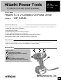
PRODUCT NAME
Hitachi 14.4 V Cordless Oil Pulse Driver
Model
WP 14DSL
MARKETING OBJECTIVE
The new Model WP 14DSL Cordless Oil Pulse Driver is equipped with a 14.4 V lithium-ion battery. Features of
the Model WP 14DSL include the following:
(1) Lightweight and compact
(2) Highest tightening speed and capacity in its class
(3) Quiet: 75 dB (Equipped with the oil pulse unit)
(4) Switchable impact rate between two modes (save mode and power mode)
With the new Model WP 14DSL, we intend to expand our market share.
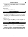
APPLICATIONS
• Tightening and loosening of small screws, tapping screws, wood screws, Teks screws, Hex screws, etc.
• Tightening and loosening of bolts are not available due to possible trouble.
SELLING POINTS
[NEW FEATURES]
Lightweight and compact
Highest tightening speed and capacity
in its class
Quiet: 75 dB
With a 2-stage switching function
(rotational speed and number of impacts)
SPECIFICATIONS AND PARTS ARE SUBJECT TO CHANGE FOR IMPROVEMENT.
International Sales Division
W
REMARKS:
• For more information about HANDLING INSTRUCTIONS, visit our website at:
http://www.hitachi-koki.com/manual_view_export/
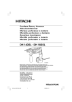
• This TECHNICAL DATA AND SERVICE MANUAL utilizes symbols to denote the company and model
names of our competitors. The symbols utilized herein are as follows:
Competitors
Symbols utilized
M
Company name
Model name
MAKITA
BTS130
CONTENTS
Page
SELLING POINTS -------------------------------------------------------------------------------------------------------------- 1
SPECIFICATIONS -------------------------------------------------------------------------------------------------------------- 4
1. Specifications------------------------------------------------------------------------------------------------------ 4
2. Optional Accessories -------------------------------------------------------------------------------------------- 5
COMPARISON WITH SIMILAR PRODUCTS---------------------------------------------------------------------------- 6
1. Comparison of Specifications --------------------------------------------------------------------------------- 6
2. Screwing Time and Capacity (Number of Screws Tightened) ----------------------------------------- 7
3. Continuous Service Durability--------------------------------------------------------------------------------- 7
PRECAUTIONS ON SALES PROMOTION ------------------------------------------------------------------------------ 8
1. Safety Instructions ----------------------------------------------------------------------------------------------- 8
2. Not Using the Pulse Driver at -5°C or Lower ------------------------------------------------------------ 10
3. About Reduction in Tighten Torque ------------------------------------------------------------------------ 11
4. Notes on use of the Charger and the Battery ----------------------------------------------------------- 11
5. Continuous Tightening Work -------------------------------------------------------------------------------- 11
6.Other Notices ---------------------------------------------------------------------------------------------------- 11
REPAIR GUIDE --------------------------------------------------------------------------------------------------------------- 12
1. Precautions on Disassembly and Reassembly --------------------------------------------------------- 12
2. Precautions on Disassembly and Reassembly of the Battery Charger --------------------------- 23
STANDARD REPAIR TIME (UNIT) SCHEDULES ------------------------------------------------------------------- 24
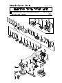
Assembly Diagram for WP 14DSL
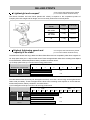
SELLING POINTS
*As of August, 2009 researched by Hitachi
(14.4 V Class Cordless Oil Pulse Driver)
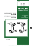
Lightweight and compact*
The Hitachi Cordless Oil Pulse Driver (Model WP 14DSL) is superior to the competitive product of
Company M in both weight and full length, and can be easily wired even in narrow places.
Full length
Maker
Model
Weight
Full length
HITACHI
WP 14DSL
1.6 kg
169 mm
HITACHI
WP 12DM
1.9 kg
177 mm
M
1.7 kg
183 mm
Highest tightening speed and
capacity in its class*
*As of August, 2009 researched by Hitachi
(14.4 V Class Cordless Oil Pulse Driver)
The table below shows how long it takes the Hitachi Pulse Driver and our competitor's pulse driver to tighten an
H/L sharp point screw (ø 4.5 x 90) into lauan wood. These are approximate values since screwing times depend
on wood hardness, ambient temperature, battery conditions, and other factors.
(1) H/L sharp point screw (4.5 mm dia. x 90 mm long), lauan wood
←
1
Manufacturer Voltage Model
HITACHI
Fast
Slow
2
3
4
14.4 V WP 14DSL
2.7
M
14.4 V
2.8
→
5
(sec.)
The table below shows how many H/L sharp point screws (4.5 mm dia. x 90 mm long) can be tightened into
lauan wood per battery. These are approximate values since screwing times depend on wood hardness,
ambient temperature, battery conditions, and other factors.
(2) H/L sharp point screw (4.5 mm dia. x 90 mm long), lauan wood
←
Manufacturer Voltage Model
20
40
Few
60
80
100
120
140
14.4 V WP 14DSL
130
12.0 V WP 12DM
105
M
14.4 V
110
HITACHI
-1-
160
Many
→
180
200
(pcs.)
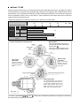
Quiet: 75 dB
While the impact mechanism of a conventional impact driver generates impact force by striking iron pieces
for impact driving, an oil pulse driver generates high impact force by applying motor rotational force to an oil
pulse section (in an oil pressure mechanism), thereby increasing oil pressure in the section and using this
force for tightening screws. The oil pulse driver is much quieter than the impact driver since it does not
strike iron pieces to generate force.
<Noise when tightening H/L sharp point screw (ø 5.3 x 120mm) into cedar lumber>
60
70
80
90
100
(dB)
Manufacturer Voltage Model
HITACHI
14.4 V WP 14DSL
75
12.0 V WP 12DM
70
14.4 V WH 14DSL
84
M
14.4 V
75
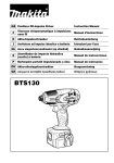
• Impact mechanism of oil pulse driver
Motor rotation
The torque-generating seal portion of
the main shaft does not match that of
the liner (see 3 ).
There is no pressure difference, and
only the liner casing and liner rotate.
Blade
Liner case
Liner
Oil
Oil
Main shaft
Before torque
generation
After torque
generation
There is no pressure
difference, and only
the liner casing and
liner rotate.
There is no pressure
difference, and only the
liner casing and liner
rotate.
Torque-generating seal
portion
Torque-generating seal portion
Torque generation
The torque-generating seal portion of
the main shaft matches that of the liner.
Four chambers of different pressure are
formed. High pressure works on the
blade and causes the main shaft to
rotate. This action generates torque.
Main shaft
Liner case
As shown in operations 1 , 2 , 3 , and 4 above, this mechanism generates one torque per revolution of
the main shaft (one impact per revolution).
-2-
With a 2-stage switching function
(rotational speed and number of impacts)
With the changeover lever, you can change impact force in two modes. Use Save mode to tighten small-diameter wood
screws or for driving screws into soft wood. Use Power mode to tighten large-diameter wood screws or for driving
screws into hard wood. It is very convenient for you to change screwing force according to the purpose of work and
work conditions.
Screwing in Save mode (16 N•m)*
• Best suitable for light load works
Use to tighten wood screws of small
Switchable
diameters or to adjust screwing!
Screwing in Power mode (30 N•m)
• Best suitable for heavy load work
Use to tighten wood screws of large
diameters!
*: Notes on use in Save mode: When operating the Pulse Driver continuously in Save mode, note
that electronic circuitry components inside the switch may get hot
and even burn in extreme cases.
-3-
SPECIFICATIONS
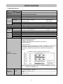
1. Specifications
Model
WP 14DSL
Item
Capacity
Tightening torque
Tip condition
Type of motor
Main body
Enclosure
Battery
Charger
Type of switch
No-load rotation speed
Impact rate
Weight
Net
Gross
Overall length x height
Type of battery
Battery
Nominal voltage
(Type
Nominal life
BSL 1430)
Nominal capacity
Machine screw*1: 4 to 8 mm
Wood screw: 3.5 mm to 9.5 mm
30 N•m (306 kgf•cm 266 in-lbs.)
6.35 mm (1/4”) bit holder
Fan-cooled, rare-earth magnet motor
Polyamide resin + elastomer -------------------------------Housing
Aluminum alloy die casting----------------------------------Hammer case
Polyamide resin------------------------------------------------Front cover
Polycarbonate resin
ABS resin
Trigger switch with forward/reverse changeover pushing button (with brake)
0 to 2,600 min-1 (power mode) / 0 to 2,000 min-1 (save mode)
0 to 1,600 min-1 (power mode) / 0 to 1,200 min-1 (save mode)
Main body (including Type BSL 1430 Battery) ---------1.6 kg
Charger unit (including cord) -------------------------------0.5 kg
4.2 kg
169 mm x 238 mm
Sealed cylindrical lithium-ion storage battery
DC 14.4 V
Charging/discharging: approximately 1,500 times
3.0 Ah
Overcharge protection system:
(1) Stop current detection
(2) Battery surface temperature detection (thermistor)
(3) 180 minute timer
Power input: 90 W
Charging time: Approx. 45 minutes [for Type BSL 1430 Battery at 20°C (68°F)]
Operable ambient temperature range: 0°C to 40°C (32°F to 104°F)
The maximum allowable temperature of the Type BSL 1430 Battery is 50°C
(122°F).
Indication method of battery charging function
Charger
(Model UC 18YRSL)
NOTE: The Model UC 18YRSL cools an overheated battery by using the
cooling fan in standby mode.
Standard
accessories
LSRK
• Charger (Model UC 18YRSL) ---------------------------------------------------1
• Battery (Type BSL 1430) ---------------------------------------------------------2
• Case -----------------------------------------------------------------------------------1
• Battery cover-------------------------------------------------------------------------1
*1: Down to 3 mm of tapping screw
-4-
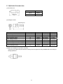
2. Optional Accessories
(1) Plus driver bit
Bit No.
Code No.
No. 2
992671
No. 3
992672
Stamped figures
Code No.
L (mm)
4 mm hexagon socket
7
992689
65 (2-9/16”)
7 (1/4”)
5 mm hexagon socket
8
996177
65 (2-9/16”)
8 (5/16”)
6 mm hexagon socket
10
985329
65 (2-9/16”)
10 (3/8”)
5/16” hexagon socket
12
996178
65 (2-9/16”)
12 (15/32”)
8 mm hexagon socket
13
996179
65 (2-9/16”)
13 (1/2”)
10 mm hexagon socket (small type)
14
996180
65 (2-9/16”)
14 (9/16”)
10 mm hexagon socket
16
996181
65 (2-9/16”)
16 (5/8”)
10 mm hexagon socket
17
996182
65 (2-9/16”)
17 (21/32”)
50mm (2”)
(2) Hexagon socket
Stamped figures
B
L
Part name
B (mm)
(3) Drill chuck adaptor set (Code No. 321823)
The drill chuck adaptor set permits the mounting of various types of locally available drills for a variety of
drilling operations.
-5-
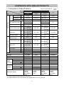
COMPARISON WITH SIMILAR PRODUCTS
1. Comparison of Specifications
Maker
Model
Catalog values
Capacity
Item
Machine screw mm
Wood screw
Ordinary bolt
Max. tightening torque N•m
width across flat of bit
mm
No-load rotation speed min-1
Impact rate
Measured values
mm
min-1
(Superior specifications:
)
HITACHI
WP 14DSL
(LSRK)
WP 12DM
(RCK)
WH 14DSL
(2SLCK)
M
4 to 8
-
4 to 8
4 to 8
3.5 to 9.5
3.5 to 9.5
M5 to M14
-
-
-
M5 to M12
M6 to M10
Power mode (P): 30
-
Save mode (S): 16
6.35
6.35
Power mode (P):
0 to 2,600
Save mode (S):
0 to 2,000
Power mode (P):
0 to 1,600
Save mode (S):
0 to 1,200
0 to 2,300
0 to 1,500
Power mode (P): 145
Save mode (S): 80
6.35
Power mode (P):
0 to 2,600
Save mode (S):
0 to 2,000
Power mode (P):
0 to 1,600
Save mode (S):
0 to 1,200
30
6.35
0 to 2,400
0 to 1,600
Main body weight
kg
1.6
1.9
1.4
1.7
Maximum
tightening torque*1
N•m
28.4
23.7
153*2
24.8
No-load rotation speed min
-1
Power mode (P):
0 to 2,632
Save mode S):
0 to 1,928
0 to 2,280
Power mode (P):
0 to 2,580
Save mode (S):
0 to 1,960
Power mode (P):
0 to 2,790
Save mode S):
0 to 2,210
-
Impact rate
min-1
0 to 1,500
0 to 1,590
Full length x height x
center height
mm
169.8 x 237.2 x 29
177 x 228 x 26.5
145 x 235 x 29
-
Main body weight
kg
1.69
1.91
1.49
1.70
Full-load load noise
dB
74.7
69.6
84.1
75.3
Equipped
Equipped
Plastic
Equipped
BSL 1430
Slide
3.0
Equipped
None
None
Plastic
None
EB 1230R
Plug-in
3.0
None
Equipped
Equipped
Plastic
Equipped
BSL 1430
Slide
3.0
Equipped
None
Equipped
Plastic
None
BL 1430
Slide
3.0
Equipped
UC 18YRSL
UC 24YH
UC 18YSL2
DC 18RA
45
21
22
22
Impact switch
LED light
Case
Battery indicator
Type
14.4V
battery
Mount type
(Li-ion/Ni-MH) Nominal capacity
Ah
Protective circuit
Model
Charger
Charging time
Battery mount type
Standard accessory
min.
Slide
• Charger
• Casing
• Plus bit
• Aux. battery
• Hook
Plug-in
• Charger
• Casing
• Plus bit
• Hook
Slide
• Charger
• Casing
• Plus bit
• Aux. battery
• Hook
*1: Torque to tighten a torque tester for one second
*2: Torque to tighten an M14 high-tensile bolt (Strength class 12.9) for 3 seconds
-6-
-
Slide
• Charger
• Casing
• Plus bit
• Aux. battery
• Hook
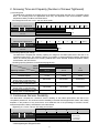
2. Screwing Time and Capacity (Number of Screws Tightened)
(1) Screwing time
The table below compares the screwing time for the Hitachi pulse driver with that of our competitor’s pulse
driver. The screwing times are approximate since they are dependent upon wood hardness, ambient
temperature, battery conditions, and other factors.
<H/L sharp point screw ø 5.3 mm x 120 mm, lauan wood>
1
Manufacturer Voltage Mode
←
Fast
2
3
4
5
6
7
HITACHI 14.4 V WP 14DSL
→
9
10
Slow
→
(sec.)
6.6
M
14.4 V
<H/L sharp point screw ø 4.5 mm x 90 mm, lauan wood>
←
7.8
Fast
1
Manufacturer Voltage Mode
8
Slow
2
3
4
HITACHI 14.4 V WP 14DSL
2.7
M
14.4 V
2.8
5
(sec.)
(2) Screwing capacity per charge
The table below compares the screwing capacity per charge for the Hitachi pulse driver with that of our
competitor's pulse driver. The screwing capacity (or numbers of screws tightened) indicates approximate
values, and actually depends on the screwing material state, screw diameter, ambient temperature, battery
characteristics, and other factors.
<Screwing capacity (Numbers of screws actually tightened) >
Maker
Model
HITACHI
WP 14DSL
14.4 V
WP 12DM
12.0 V
M
14.4 V
Battery
BSL 1430
EB 1230R
BL 1430
Nominal capacity
3.0 Ah
3.0 Ah
3.0 Ah
590 screws
440 screws
540 screws
300 screws
235 screws
250 screws
130 screws
105 screws
110 screws
60 screws
50 screws
50 screws
Tightening condition
H/L sharp point screw ø 4.0 x 50L
(lauan wood, no prepared hole)
H/L sharp point screw ø 4.2 x 75L
(lauan wood, no prepared hole)
H/L sharp point screw ø 4.5 x 90L
(lauan wood, no prepared hole)
H/L sharp point screw ø 5.3 x 120L
(lauan wood, no prepared hole)
3. Continuous Service Durability
The table below compares the continuous service durability of the Hitachi pulse driver with that of our
competitor's pulse driver. The continuous service durability in the table shows approximate values, and actually
depends on the presence of any wood knots, wood hardness due to the percentage of moisture content,
ambient temperature, battery characteristics, and other factors.
<Tightening of ø 4.5 mm x 90 mm H/L sharp point screws>
Number of batteries
2
3
1
4
Manufacturer Voltage Model
3.3 batteries*1
(500 screws)
HITACHI 14.4 V WP 14DSL
M
3.3 batteries*1
(315 screws)
14.4 V
*1: After continuous screwing work by 3.3 batteries, the oil pulse and motor portions get hot, but the pulse driver can
continue tightening H/L sharp point screws.
-7-
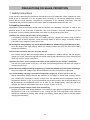
PRECAUTIONS ON SALES PROMOTION
1. Safety Instructions
In the interest of promoting the safest and most efficient use of the Model WP 14DSL Cordless Oil Pulse
Driver by all our customers, it is very important when concluding a sale that the salesperson carefully
ensure that the buyer seriously recognizes the importance of the Handling Instructions, and fully
understands the precautions listed on the Caution Plate and Nameplate attached to each tool.
A. Handling instructions
Salespersons must be thoroughly familiar with the contents of the Handling Instructions in order to give
pertinent advice to the customers. In particular, they must possess a thorough understanding of the
precautions on using cordless tools that differ from those of ordinary electric power tools.
(1) Before use, ensure that the battery is fully charged.
A new battery is not fully charged. Even if the battery was fully charged at the factory, long periods of
inactivity, such as during shipment, cause the storage battery to lose its charge. Customers must be
instructed to fully charge the battery prior to use.
(2) To charge the storage battery, only use the dedicated Model UC 18YRSL Charger provided with the tool.
Given the design of the rapid-charging feature (for charging in about one hour), the use of other battery
chargers is hazardous.
(3) Follow the prescribed steps for using the charger.
First connect the Type BSL 1430 Storage Battery to the Model UC 18YRSL Charger, and then plug the
charger into an AC outlet (ensuring that the voltage matches that indicated on the unit). Reversing this
order may result in charger malfunction.
(4) Ensure the power source voltage is the same as that indicated on the charger’s nameplate.
The use of any other power source (e.g., DC outlet, fuel powered generator) will cause the charger to
overheat and burn out.
(5) Do not use any voltage-increasing equipment (e.g., transformer) between the power source and charger.
Using the charger with voltage higher than that indicated on the unit will result in malfunction.
(6) Conduct battery charging in an ambient temperature range of 0° to 40 °C (32 °F to 104 °F).
Special temperature-sensitive devices are employed in the charger to permit rapid charging. Ensure
that customers are instructed to use the charger within the indicated ambient temperature range. At
temperatures below 0 °C (32 °F), the thermostat will not function properly, and the storage battery may
be overcharged. At temperatures above 40 °C (104 °F), the storage battery cannot be sufficiently
charged. The optimum temperature range is 20 °C to 25 °C (68 °F to 77 °F).
(7) The battery charger should not be used continuously.
Charging more than three storage batteries in succession at high ambient temperature will cause the
temperature of coils on the transformer to rise, running the risk of the temperature fuse inside the
transformer inadvertently melting. After charging one battery, please wait at least 15 minutes before
charging the next battery.
-8-
(8) Do not insert foreign objects into the air vents on the charger.
The charger case is equipped with air vents to protect internal electronic components against
overheating. Caution the customer not to drop or insert such foreign matter as metallic or flammable
objects into the air vents. This could cause electrical shock, fire or other serious hazards.
(9) Do not attempt to disassemble the storage battery or charger.
Special devices such as a thermostat are built into the storage battery and charger to permit rapid
charging. Incorrect parts replacement and/or wiring will cause malfunctions that could result in fire or
other hazards. Instruct the customer to bring these units to an authorized service center for any
necessary repair or replacement.
(10) Properly dispose of the storage battery.
Ensure that all customers understand that storage batteries should be returned to the Hitachi power tool
sales outlet or authorized service center when the batteries can no longer be recharged or repaired. If
thrown into a fire, the batteries may explode.
(11) Effects of permanent magnet
The Model WP 14DSL has a strong permanent magnet in its motor. Please instruct the customers about
dust adhering to the Model WP 14DSL and the effects on electronic devices as follows:
• Do not place the Model WP 14DSL on a workbench or in a work area subject to the scattering of metal
dust.
• Do not touch a dusty Model WP 14DSL. Instruct the customers to remove adhered dust with a brush.
• The users of such medical electronic products such as a pacemaker must not use or approach the
Model WP 14DSL.
• Do not bring precision equipment such as a mobile phone or electronic recording media such as a
magnetic card near the Model WP 14DSL.
(12) Keep the battery free of dust.
• Protect the battery against being covered with dust during operation.
• Protect the battery against being covered with dust accumulated on the Model WP 14DSL during
operation.
• Do not leave the battery in a dusty area when not in use.
• Remove dust from the battery and store it separately from such metallic parts as screws and nails.
B. Caution plate
(1) The following cautions are listed on the Nameplate attached to the main body of each tool.
[For the USA and Canada]
WARNING
• To reduce the risk of injury, user must read and understand Instruction Manual.
AVERTISSEMENT
• Afin de réduire le risque de blessures, I'utilisateur doit lire et bien comprendre
le mode d'emploi.
-9-
(2) The following cautions are listed on the Nameplate attached to each storage battery.
[For Europe]
CAUTION
• Read thoroughly HANDLING INSTRUCTIONS before use.
• Do not disassemble nor throw into fire.
[For the USA and Canada]
CAUTION
• Read thoroughly HANDLING INSTRUCTIONS before use.
• Do not disassemble nor throw into fire.
(3) The following cautions are listed on the Nameplate attached to the Model UC 18YRSL Charger.
[For the USA and Canada]
• For safe operation, see instruction manual.
CAUTION • Charge HITACHI rechargeable batteries types BSL 14, BSL 18
series. Other types of batteries may burst causing personal injury and damage.
• Charge between 32 °F and 104 °F. Rest 15 minutes between the charging of
batteries. • Indoor use only. • Replace defective cord immediately. • Do not install on
or over combustible surfaces
AVERTISSEMENT
2. Not Using the Pulse Driver at -5 °C or Lower
Do not use the Pulse Driver in a working environment of –5 °C or lower or after storing it for a long time at –5 °C
or lower. Using the Pulse Driver under such a condition will generate no impact (torque) when you operate the
switch or may disable the motor due to overload and the extremely reduced number of impacts. Please tell the
users to warm up the Pulse Driver (by tightening some short screws before beginning ordinary tightening work.
-10-
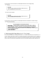
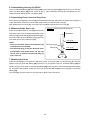
3. About Reduction in Tighten Torque
(1) Battery voltage ------------------------------The tightening torque of the Pulse Driver is affected by battery voltage.
The battery voltage gradually goes down as more screws are
tightened. In particular, the battery voltage quickly drops just before
activation of the over-voltage prevention circuit.
This symptom is specific to cordless oil pulse drivers and impact
drivers/wrenches. Therefore, please ask the users to understand
these characteristics before using the tool.
Notices on use of Type BSL 1430 battery (lithium ion battery)
To prolong battery service life, the Pulse Driver is equipped with a
protective function to stop output. In case of low remaining battery
charge (when the battery voltage drops down to approx. 8 V), this
function stops the motor, even if you are pulling the switch. This is no
failure since it is caused by the protective function.
In this case, please tell the user to recharge the battery as soon as
possible.
(2) Low ambient temperature ----------------At very low ambient temperature, oil and grease in the Pulse Driver
become less viscous and lubricative, thereby resulting in reduced
tightening torque.
(3) Different kinds of wood --------------------The hardness of wood depends upon percentage of moisture in the
wood. The tighten torque reduces when the wood is hard.
4. Notes on use of the Charger and the Battery
(1) The battery should not be recharged just after you stop using the Pulse Driver .
If the battery (Type BSL 1430) becomes very hot (such as when exposing the Pulse Driver to direct
sunlight for a long time or just after you stop using the Pulse Driver), the charge indicators of the
charger may not light when you connect the Pulse Driver to the charger. See the table below for the
chargeable battery temperature range.
In such a case, please tell the user to place the battery pack in a cool well-ventilated place, allow it to
fully cool down, and then recharge it.
The charging time ranges from a few minutes to about 10 minutes, depending on tightening load,
service hours, ambient temperature, and other factors.
<Chargeable battery temperature range>
Battery
BSL 1430
Battery temperature
UC 18YRSL
0 °C to 50 °C
5. Continuous Tightening Work
(1) When used continuously to tighten wood screws, the Pulse Driver becomes hot and may exhibit degraded
performance (such as reduced torque). In this case, allow the Pulse Driver to fully cool down. Once the
Pulse Driver has cooled down, you can use it again.
Such continuous work should be avoided, with about a 15 minute idle period prior to using the Pulse
Driver again after changing the batteries.
(2) The front cover of the Pulse Driver becomes very hot during continuous tightening work. Do not touch it.
6. Other Notices
(1) Countermeasures against impacts and water
This Pulse Driver contains high-precision parts. Be careful not to drop it, subject it to any strong force,
or wet it with water. These actions may cause failure or malfunction of the Pulse Driver.
-11-
REPAIR GUIDE
WARNING: Always remove the battery from the main body before starting repair or maintenance work.
Because the tool is cordless, leaving the battery inside and inadvertently activating the
switch will start unexpected motor rotation, possibly resulting in serious injury.
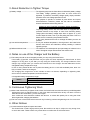
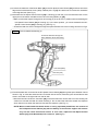
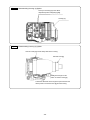
1. Precautions on Disassembly and Reassembly
The [Bold] numbers in the descriptions below correspond to item numbers in the Parts List and exploded
view assembly diagram of the Model WP 14DSL.
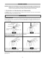
Disassembly
1. Guide Sleeve (A)
Follow the steps in Fig.1. You can take out Retaining Ring [1], Retainer [2], Guide Spring [3], and Guide
Sleeve (A) [4] in this order. Be careful not to lose the two Steel Balls D3.175 [12] in the main shaft hole of
the Pulse Unit [13].
Small flat-blade screwdriver
Pulse Unit [13]
Retaining Ring [1]
Retainer [2]
Retaining Ring [1]
Opening
Guide Sleeve (A) [4]
Fig. 1-1
Secure the body of the Pulse Driver, match the
opening of Retaining Ring [1] to the notch of the main
shaft in Pulse Unit [13], and then insert the small flatblade screwdriver at an angle.
Fig. 1-3
Slide the small flat-blade screwdriver under one
side of the gap of the Retaining Ring [1].
Fig. 1-2
Press down Retainer [2] with the small flat-blade
screwdriver.
Fig. 1-4
Slowly raise the Retaining Ring [1] using the end
face of Guide Sleeve (A) [4] as a fulcrum.
One side of the opening of Retaining Ring [1] rises. Slowly lift the other portion of the opening with the
small flat-blade screwdriver. You can then remove it. Do not lift it up too quickly. Otherwise, Retaining Ring
[1] will pop out.
-12-
2. Front Cap, Front Cover
Insert the small flat-blade screwdriver between the Front Cap [5] and Front Cover [6], and then remove
both from Hammer Case [7].
3. Hook
Remove Truss Hd. Screw M4 (Black) [38] and Hook [37]. You can conduct disassembly work without
removing Hook [37]. This would help simplify later disassembly work.
4. Carbon Brush
Remove the two Brush Caps [32] of the left and right Carbon Brushes 5 x 6 x 11.5 [31]. Remove each
Carbon Brush 5 x 6 x 11.5 [31] by hooking the flange of Carbon Brush 5 x 6 x 11.5 [31] with the small flatblade screwdriver or similar tool.
5. Housing (B)
Remove the nine Tapping Screws (W/Flange) D4 x 20 (Black) [33] from the Pulse Driver. Housing (B) can
only be detached when the Brush Caps [32] are removed. Be sure to remove the Brush Caps [32] before
detaching Housing (B). You can remove the Strap (Black) [48] after removing Housing (B).
6. DC-Speed Control Switch
(1) Th e FET of the DC-Speed Control Switch [45] is firmly fitted to the housing. Insert the tip of the small
flat-blade screwdriver between the FET and Housing (B), and then pry up and remove the FET.
(2) You can remove the Hammer Case [7], Pulse Unit [13], Inner Cover (D) [25], Armature DC 14.4V [26],
Magnet (D) [27], Brush Block [30], DC-Speed Control Switch [45], Controller [46], terminal support,
and LED light together as one unit. You can also remove Pushing Button (A) [42].
NOTE: Be careful not to damage the three leads extending from the FET. If the leads are broken,
the switching speed cannot be varied.
7. Impact mechanism parts
In case of Pulse Unit [13] failure, replace the entire unit. Do not disassemble it.
8. Switch assembly
Remove the two Machine Screws (W/Sp. Washer) M3 x 5 [41] from the flag terminals when removing the
two lead wires (red and black) of Brush Block [30] from the DC-Speed Control Switch [45].
NOTE: Three FET lead wires are soldered to the DC-Speed Control Switch [45]. Do not disassemble
this setup.
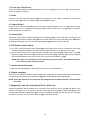
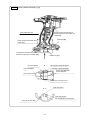
9. Magnet (D), Yoke (A), Dust Guard Fin (C), Side Yoke
Magnet (D) [27] has strong magnetic force. Therefore, firmly hold Inner Cover (D) [25] and slide it in the
direction of B (see Fig. 2) to remove it. Similarly, Dust Guard Fin (C) [29] and Side Yoke [50] are also
magnetically attracted to Magnet (D) [27]. Firmly hold Magnet (D) [27] and pull both parts in the radial
direction for removal. You can remove Yoke (A) [28] in the same manner.
-13-
Fig. 2 • Magnet (D), Yoke (A), Dust Guard Fin (C), Side Yoke
B
Magnet (D) [27]
Yoke (A) [28]
Inner Cover (D) [25]
Armature
DC 14.4 V [26]
B
Armature DC 14.4 V [26] (pinion)
Damper [24]
Inner Cover (D) [25]
Ring Gear (E) [21]
Armature DC 14.4V [26]
Side Yoke [50]
Brush Block [30]
Dust Guard Fin (C) [29]
Fit the projected portion of Dust Guard Fin (C) [29] to
the depressed portion of Brush Block [30].
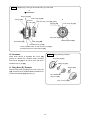
10. Armature
Fig. 3 • Ring Gear (E), Damper
Press down the tip of Armature DC 14.4V [26]
(pinion) to remove the armature while receiving
Inner Cover (D) [25] so as not to touch the fan of
Armature DC 14.4V [26].
Ring Gear (E) [21]
Washer (E) [22]
11. Ring Gear (E), Damper
Damper [24]
Remove Ring Gear (E) [21] from Inner Cover (D)
[25], and then use a small flat-blade screwdriver to
remove the Damper [24]. (See Fig. 3.)
BALL BEARING
6901VV-N [23]
Inner Cover (D) [25]
-14-
Reassembly
Conduct reassembly by reversing the disassembly procedures, but note the following:
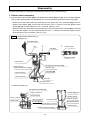
1. Switch-related reassembly
(1) Connect wires of the Controller [46] or DC-Speed Control Switch [45] according to the connection diagram
(Fig. 4) when replacing these units individually. Item (1) is omitted when replacing the Switch Ass'y [47].
• Solder the red and white lead wires extending from the upper part of the Controller [46] to the DCSpeed Control Switch [45]. Connect the red lead wire to the "+" terminal of the DC-Speed Control
Switch [45] and the white lead wire to the "-" terminal. (See Fig. 4 (a).)
• Solder the black and white lead wires extending from the lower part of the Controller [46] to terminals
of the terminal support. Connect the black lead wire to the "-" terminal of the terminal support and the
white lead wire to the LD terminal. (See Fig. 4 (b).)
Fig. 4 • Switch-related reassembly (1)
Connection diagram (a)
Brush Block [30]
FET
Lead wire (red)
LED light
Lead wire (black)
Flag terminal
DC-Speed Control Switch [45]
Machine Screw
(W/Sp. Washer) M3 x 5 [41]
Lead wire (red)
Controller [46]
Lead wire (white)
Lead wire (brown)
Capacitor
Terminal support
Connection diagram (b)
DC-Speed Control Switch [45]
Switch (+) terminal
Controller [46] (front)
Lead wire (red))
Lead wire (black)
Switch (-) terminal
Lead wire (white)
Lead wire (brown)
Lead wire (white)
Controller [46] (front)
Terminal support (-) terminal
Lead wire (brown)
Terminal support (+) terminal
Terminal support
Terminal support LD terminal
-15-
(2) Connect the lead wire of the Brush Block [30] to the DC-Speed Control Switch [45], and then secure the
flag terminal with Machine Screw (W/Sp. Washer) M3 x 5 [41]. Be careful not to reverse the orientation
of the flag terminal. (See Fig. 4.)
(3) Assemble the DC-Speed Control Switch [45] in Housing (A) with the jut of the CW/CCW lever on the
upper part of the switch inserted into the hole of Pushing Button (A) [42].
• Make sure that the Impact Change lever of Housing (A) is set to the "P" position when assembling the
DC-Speed Control Switch [45] in Housing (A). In the other position, you cannot assemble the DCSpeed Control Switch [45] in Housing (A). (See Fig. 6.)
• Thread the lead wire of the LED light through the space between ribs of the housing as shown in Fig.5.
Fig. 5 • Switch-related reassembly (3)
Thread the lead wire through the
space between ribs of the housing
Lead wire (black)
Lead wire (red)
(4) Thread the lead wire connected to the DC-Speed Control Switch [45] through the space between ribs as
shown in Fig. 6. Insert the white lead wire to the left side of the rib, followed by the red and brown lead
wires in this order to the right side from the far side.
• Bend the lead wire under the Controller [46] so that the lead wire can be well set in the housing. Be
careful not to break the lead wire when bending it. Do not bend the lead wire toward the capacitor
since failure occurs when the lead wire touches the capacitor. (See Fig. 6.)
NOTE: When contaminated with black oxides or having separated plated films, the contacts of
the DC-Speed Control Switch [45] with the battery of the terminal support will become
very hot and cause Pulse Driver failure. In such case, replace the DC-Speed Control
Switch [45] (Code No.326784) with a new one. (See Fig. 6.)
-16-
Fig. 6 • Switch-related reassembly (3)(4)
Set the Impact Change lever of
Housing (A) to the "P" position for
reassembly.
Insert white lead wire.
Controller [46]
Insert red and brown lead wires
in this order.
Thread brown lead wire into space
between housing and Controller [46].
Terminal support
D
Lead wire (white)
D
LD terminal of terminal support
"-" terminal of terminal support
Lead wire (black)
Do not bend lead wire
toward capacitor.
Lead wire (brown)
"+" terminal of terminal support
A-A
Lead wire (white)
Lead wire (brown)
Put red lead wire in this groove.
Lead wire for LED light
-17-
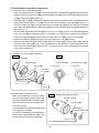
2. Reassembly of machine components
(1) Armature DC 14.4V related reassembly
• Fit the jut of Dust Guard Fin (C) [29] to the depressed portion of Magnet (D) [27] and match the outer
diameter of Dust Guard Fin (C) [29] with that of Magnet (D) [27] when reassembling Dust Guard Fin
(C) [29] to Magnet (D) [27]. (See Fig. 7.)
• Assemble Yoke (A) [28] to Magnet (D) [27] with the depressed portion of Yoke (A) [28] fitted to the
flange shape of Dust Guard Fin (C) [29]. (Do not reverse the orientation of Yoke (A) [28].) (See Fig. 7.)
• Fit the jut of Side Yoke [50] to the depressed portion of Magnet (D) [27] and match the outer diameter
of the Side Yoke [50] with that of Magnet (D) [27] when assembling the Side Yoke [50] to Magnet (D)
[27]. (See Fig. 7.)
• Press-fit BALL BEARING 6901VV-N [23] to Inner Cover (D) [25]. Insert the two Dampers [24] into
Inner Cover (D) [25] according to shape. Fit the detent rib of Ring Gear (E) [21] to the depressed
portion of the Damper [24], and then press-fit Armature DC 14.4V [26] to Inner Cover (D) [25].
• Combine the Magnet (D) [27] assembly with the Armature DC 14.4V [26] assembly.
• Mount the Idle Gear Set [17], Needle Roller [19], and Washer [16] on Gear Holder [18], and then
insert the Gear Holder [18] to Ring Gear (E) [21] while paying attention to gear engagement. Then,
make sure Gear Holder [18] rotates smoothly. If it does not rotate, gear engagement is incomplete.
Correct gear engagement.
• Armature DC 14.4V related reassembly
Fig. 7
Fig. 8
Side Yoke [50]
Magnet (D) [27]
Brush Block [30]
Yoke (A) [28]
Depressed part
Dust Guard Fin (C) [29]
Projected part
Dust Guard
Fin (C) [29]
Depressed part
Projected part
Flange
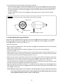
(2) Reassembling the Hammer Case
Make sure the Hammer Case [7] contains
the Felt Packing [8], Packing Washer [9],
and BALL BEARING 6801VVCMSRL [10],
and then insert the Pulse Unit [13] into the
Hammer Case [7].
Press-fit Ball Bearing 6902VVCMPS2L [15]
to the Bearing Cover [14].
Fit the jut of the Bearing Cover [14] having
Ball Bearing 6902VVCMPS2L [15] to the
groove portion of the Hammer Case [7].
Fig. 9 • Reassembling Hammer Case
Hammer Case [7]
Felt Packing [8]
Ball Bearing
6801VVCMSRL [10]
Packing Washer [9]
Insert with projected portion in Felt Packing [8]
-18-
(3) Connecting hammer case assembly and armature assembly
Mount the Washer [16] on the Gear Holder [18] and push Inner Cover (D) [25] into the Hammer Case
[7] while matching the hexagonal portion of the Pulse Unit [13] with that of the Gear Holder [18]. Make
sure the end surface of Inner Cover (D) [25] is located in the farther side than the end surface of the
Hammer Case [7].
Locate so that the rib of Inner Cover (D) [25] is at right angles to the rib of the Hammer Case [7].
(See Fig. 10.)
Fig. 10 • Connecting hammer case assembly and armature assembly
Inner cover rib
Hammer case rib
Hammer Case [7] end surface
3. Reassembling Housing (A).(B) Set
Mount the Pulse Unit [13], Hammer Case [7], Inner Cover (D) [25] (including Armature DC 14.4V [26]),
Magnet (D) [27] (including Yoke (A) [28], Dust Guard Fin (C) [29], and Side Yoke [50]), and the Brush
Block [30] together in Housing (A). (See Fig. 14.)
Notices on reassembly:
• Be sure to fit the projected portion of Dust Guard Fin (C) [29] to the depressed portion of the Brush Block
[30] in advance. (See Fig. 8.)
• Fit the detent depressed portion of Magnet (D) [27] to the jut of Housing (A) at reassembly.
(See Fig. 7 and Fig. 11.)
• Make the detent jut of Hammer Case [7] contact with the detent receiver of the housing (see Fig. 13)
when fitting the Hammer Case [7] to the housing. Thread the lead wire of LED light through the space
between the housing and Hammer Case [7] as shown in Fig.12.
• Make sure the Hammer Case [7] is correctly set in the housing. If the Hammer Case [7] is not set in the
preset groove of the housing or if the rib of Inner Cover (D) [25] is not at a right angle to the rib of the
Hammer Case [ 7] , then re-fit the Hammer Case [7] to the housing. (See Figs. 10, 12, and 13.)
Only when the Hammer Case [7] is correctly fitted can its axial movement be prevented. Therefore, make
sure that the Hammer Case [7] is correctly fitted to the housing.
• Apply silicon grease (Shin-Etsu Chemical Co., Ltd. KS609) to the DC-Speed Control Switch [45] surfaces
where the FET and Dust Guard Fin (C) [29] contact each other before assembling the DC-Speed Control
Switch [45] in Housing (A).
NOTE: Without silicon grease on the surface, the FET becomes very hot. Bend the three lead
wires from the FET and pass them over the DC-Speed Control Switch [45] without touching
Pushing Button (A) [42] as shown in Fig.14. (See Fig.14.)
-19-
Fig. 11 • Reassembling Housing (A).(B)Set
Fit the jut of Housing (A) to the detent
depressed portion of Magnet (D) [27].
Housing (A)
Fig. 12 • Reassembling Housing (A).(B)Set
Hammer Case [7] must be firmly fitted to the housing.
Hammer Case [7]
Mount the LED light on this
portion of Hammer Case [7].
Thread the LED lead wire through the space between the
detent portion of Hammer Case [7] and the housing.
-20-
Fig. 13 • Reassembling Housing (A).(B)Set
Detent jut of Hammer Case [7]
Make the detent portion of Hammer Case [7]
touch this portion of the housing.
Fig. 14 • Reassembling Housing (A).(B)Set
The blade portion of Dust Guard Fin (C) [29]
must come under the rib of Housing (A).
Packing [44]
Lock Nut M4
(Black) [43]
Strap (Black) [48] insertion boss
Packing [44]
-21-
4. Reassembling Housing (A).(B)Set
Insert Lock Nut M4 (Black) [43] and Packing [44] into Housing (A).(B)Set [39] as shown in Fig.14, and then
insert the Strap (Black) [48] into the boss of Fig.14. Next, assemble Housing (B) and tighten the nine
Tapping Screws (W/Flange) D4 x 20 (Black) [33].
5. Remounting Front Cover and Front Cap
Fit the Front Cover [6] and Front Cap [5] to the assembled housing. Make sure the PCB of the LED light is
in the LED holder, and fit the jut of the LED holder to the jut of the Hammer Case [7].
After setting the Front Cover [6], mount the Front Cap [5] and secure the Front Cover [6].
6. Mounting Guide Sleeve (A)
Fig. 15 • Mounting Guide Sleeve (A)
Insert the two Steel Balls D3.175 [12] into the main
shaft hole of the Pulse Unit [13], reassemble Guide
Sleeve (A) [4], Guide Spring [3], and Retainer [2] in
this order, and then fit the Retaining Ring [1] to the
main shaft groove of the Pulse Unit [13].
NOTE:
• Orient the shoulder portion of the Retainer [2]
towards the bit at assembly.
• The Retaining Ring [1] may be deformed when
disassembled and Guide Sleeve (A) [4] may
fall. Be sure to replace the Retaining Ring [1]
with a new one.
Push down.
J-295 jig (B)
for retaining ring
Retaining Ring [1]
Retainer [2]
J-295 jig (A)
for retaining ring
7. Mounting the Hook
Insert the Hook [37] into the groove in the lower portion of the side surface of Housing (A),(B), and then
tighten Truss Hd. Screw M4 (Black) [38] to secure it. Do not tighten Truss Hd. Screw M4 (Black) [38] too
quickly. Doing so may result in Lock Nut M4 (Black) [43] becoming idle in the housing and possibly sliding
off. To prevent this situation, slowly turn Truss Hd. Screw M4 (Black) [38] so as to engage Lock Nut M4
(Black) [43].
The Hook [37] can be mounted on any side (left or right) of the Pulse Driver
-22-
Application of lubricant
(1) ATTOLUB MS No. 2
• Armature DC 14.4V [26] pinion gear face, Ring Gear (E) [21] face, and gears of the two Idle Gear
Sets [17]
• Two Steel Balls D3.175 [12]
(2) HITACHI MOTOR GREASE No. 29
• Main shaft (Pulse Unit [13] component) surface on which Guide Sleeve (A) [4] slides
• Housing (A) assembly surface on which Lever (C) [40] slides
(3) MOLUB-ALLOY 777-1
• ø 5 holes of the two Idle Gear Sets [17]
• Entire peripheral surface of the Needle Roller [19]
Checks after Reassembly
Check the following after reassembly.
(1) ON/OFF check of the LED light and the battery indicator lamps
Press the Light switch of the Controller [46] and make sure that the LED lights. After the LED lights,
press the Light switch once more and make sure the LED goes off.
Then press the Battery Indicator switch and make sure that both two battery indicator lamps light. Use
the fully charged battery pack for Lamp ON/OFF checks and hold down the Battery Indicator switch
during the Lamp ON/OFF check. When you release the Battery Indicator switch, the battery indicator
lamps go off.
(2) Rotational direction check
Check and make sure the rotational direction of the Pulse Unit [13] matches the direction of rotation
made when you press Pushing Button (A) [42]. When you press Pushing Button (A) [42] to the (R)
position, the Pulse Unit [13] must rotate right (clockwise) (when viewed from the back opposite to Guide
Sleeve (A) [4]).
Screw Tightening Torques
• Tapping Screw (W/Flange) D4 x 20 (Black) [33] ------------------------ 1.96 ± 0.49 N•m {20 ± 5 kgf•cm}
• Machine Screw (W/Sp. Washer) M3 x 5 [41] ---------------------------- 0.29 to 0.39 N•m {3 to 4 kgf•cm}
• Brush Cap [32] ------------------------------------------------------------------ 0.78 ± 0.10N•m {8 ± 1 kgf•cm}
• Truss Hd. Screw M4 (Black) [38] ------------------------------------------- 1.8 ± 0.40 N•m {18 ± 4 kgf•cm}
2. Precautions on Disassembly and Reassembly of the Battery Charger
Refer to the Technical Data and Service Manual for precautions on disassembly and reassembly of the
Model UC 18YRSL Battery Charger.
-23-
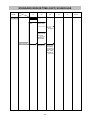
STANDARD REPAIR TIME (UNIT) SCHEDULES
MODEL
Variable
10
Fixed
20
30
Work Flow
WP 14DSL
Hook
Switch Ass'y
Housing
(A). (B)Set
Inner Cover (D)
Armature
DC 14.4V
Magnet (D)
Brush Block
General assembly
Guide Sleeve (A)
Hammer Case
Ring Gear (E)
-24-
Pulse Unit
Bearing Cover
Ball Bearing
6902VVCMPS2L
Idle Gear Set
Gear Holder
Ball Bearing
6901VV-N
40
50
60 min.
LIST NO. H846
CORDLESS OIL PULSE DRIVER
Model WP 14DSL
2010 • 10 • 6
(E2)
1
2
3
501
502
503
504
4
505
5
506
507
6
508
7
20
8
9
10
21
11
22
12
23
13
24
25
14
26
15
50
16
17
27
18
28
19
29
30
32
31
33
42
39
34
41
41
40
43
35
44
45
46
44
43
49
47
36
48
37
38
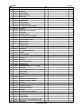
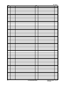
PARTS
ITEM
NO.
WP 14DSL
CODE NO.
DESCRIPTION
NO.
USED
1
995-933
RETAINING RING
1
2
307-899
RETAINER
1
3
995-931
GUIDE SPRING
1
4
307-782
GUIDE SLEEVE (A)
1
5
322-239
FRONT CAP
1
6
331-958
FRONT COVER
1
7
331-833
HAMMER CASE
1
8
322-218
FELT PACKING
1
9
322-219
PACKING WASHER
1
10
322-220
BALL BEARING 6801VVCMSRL
1
11
996-184
BIT PIECE
1
12
959-148
STEEL BALL D3.175 (10 PCS.)
2
13
331-835
PULSE UNIT
1
14
322-217
BEARING COVER
1
15
690-2VV
BALL BEARING 6902VVCMPS2L
1
16
313-058
WASHER
1
17
326-295
IDLE GEAR SET (2 PCS.)
2
18
322-221
GEAR HOLDER
1
19
319-914
NEEDLE ROLLER
2
HITACHI LABEL
1
20
21
326-787
RING GEAR(E)
1
22
319-911
WASHER (E)
1
23
323-118
BALL BEARING 6901VV-N
1
24
319-909
DAMPER
2
25
326-786
INNER COVER(D)
1
26
360-752
ARMATURE DC 14.4V
1
27
322-744
MAGNET (D)
1
28
324-828
YOKE (A)
1
29
324-830
DUST GUARD FIN (C)
1
30
321-662
BRUSH BLOCK
1
31
999-054
CARBON BRUSH 5 X 6 X 11.5 (1 PAIR)
2
32
319-918
BRUSH CAP
2
33
301-653
TAPPING SCREW (W/FLANGE) D4 X 20 (BLACK)
9
34
NAME PLATE
1
35
HITACHI PLATE
1
36
326-783
LEVER(B)
1
37
330-666
HOOK
1
38
327-001
TRUSS HD. SCREW M4 (BLACK)
1
39
329-710
HOUSING (A).(B)SET (GREEN)
1
40
326-782
LEVER(C)
1
41
994-532
MACHINE SCREW (W/SP. WASHER) M3 X 5
2
42
321-661
PUSHING BUTTON (A)
1
43
327-002
LOCK NUT M4 (BLACK)
2
44
327-004
PACKING
2
45
326-784
DC-SPEED CONTROL SWITCH
1
46
329-708
CONTROLLER
1
47
329-707
SWITCH ASS'Y
1
48
306-952
STRAP (BLACK)
1
49
330-068
BATTERY BSL 1830 (EUROPE, AUS, NZL)
2
50
323-327
SIDE YOKE
1
-2-
*ALTERNATIVE PARTS
REMARKS
10 - 10
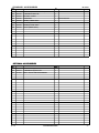
STANDARD ACCESSORIES
ITEM
NO.
CODE NO.
501
WP 14DSL
DESCRIPTION
NO.
USED
CHARGER (MODEL UC18YRSL)
1
502
983-006
+ DRIVER BIT NO.2 65L
1
503
329-897
BATTERY COVER
1
504
329-440
CASE ASS'Y
1
505
324-096
KNOB (L) DARK GRAY
1
506
324-090
HANDLE (DARK GRAY)
1
507
324-099
KNOB (R) DARK GRAY
1
508
324-093
LATCH (DARK GRAY)
2
REMARKS
INCLUD.505-508
OPTIONAL ACCESSORIES
ITEM
NO.
CODE NO.
DESCRIPTION
NO.
USED
601
992-671
+ DRIVER BIT (B) NO.2 50L
1
602
992-672
+ DRIVER BIT (B) NO.3 50L
1
603
321-823
DRILL CHUCK AND ADAPTER SET
1
10 - 10
*ALTERNATIVE PARTS
REMARKS
-3-
WP 14DSL
ITEM
NO.
-4-
CODE NO.
DESCRIPTION
NO.
USED
*ALTERNATIVE PARTS
REMARKS
Printed in Japan 10 - 10
(101006N)