1
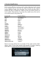
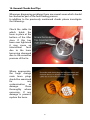
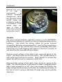
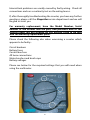
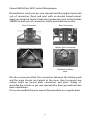
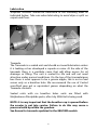
Scooter
Service Manual
Index
1. Safety advice.
2. Warranty Information.
3. Tools required.
4. Product identification.
5. Tiller head components checks and re-fitting.
6. Body panel removal.
7. Seat removal and adjustments.
8. Wheels and tyres.
9. Main controller checks.
10. Battery and battery charging information.
11. Battery removal and testing.
12. Brake removal and testing.
13. Motor brush removal and checks.
14. General checks and tips.
15. Controller errors and diagnostic guide.
16. Troubleshooting guide.
17. Annex & Wiring diagrams.
2
1. Safety Advice
Always observe a safe working practice.
Scooters and their component parts such as batteries and subassemblies can be very heavy so care must be taken when lifting and
carrying/moving. Always seek the assistance of a colleague or use
suitable lifting equipment wherever possible.
Be aware of where component parts are placed when dismantling a
scooter. Do not leave parts in walkways or in places where they may
fall and cause injury (edge of a bench etc.).
Never attempt maintenance or repair if the scooter is connected to
the mains power supply. Also disconnect the batteries to prevent any
unexpected movement that could result in injury.
3
2. Warranty Information
This is the text from the rear cover of the user manuals:
“This is to certify that your Roma Medical/Shoprider® product is
warranted for a period of 12 months from the date of original
purchase. This warranty is not transferable.
Should a defect or operating fault arise within this period the Dealer
from where the product was originally purchased should be notified
immediately. Failure to register the fault may invalidate the warranty.
Roma Medical warrants that if a fault occurs within this period due to
faulty workmanship or materials that the product will be repaired (or
replaced at the Companys discretion) free of charge.
Any unauthorised modifications will invalidate the warranty.
Parts which are subjected to normal wear and tear, accidental
damage, neglect or misuse are excluded from this warranty. Normal
wear and tear includes tyres, chassis covers, bulbs, seat coverings etc.
Component parts replaced outside this period carry a six-month
warranty. (Standard terms and conditions apply for this period).”
Please note: Battery warranties MUST be accompanied by a valid
test certificate. A multimeter reading will not be sufficient to
determine a batterys performance.
4
3. Tools Required
The following list is a guide to what tools are required to comfortably
maintain powered scooters.
•
•
•
•
•
•
•
•
•
•
•
•
•
•
•
•
•
Multimeter
Set of metric allen keys
Socket set (metric)
Set of open end spanners from 3mm to 15mm
Magnetic tipped screwdriver set
Bondlock B270 / B220 thread locking compound
Torque wrench – up to 25Nm rated
Wire stripper
Crimp tool and crimps
Mole grips
Rubber mallet
Stanley knife
Circlip pliers
Pliers (long nose and combination)
Tyre pump and pressure gauge
Tape measure and metal rule
Soldering iron
Recommended Stock Spares
Although Roma Medical carries a comprehensive stock of spare parts
it is recommended that certain parts should be to hand, these would
include:Motor Brushes
Blade Fuses
Various Nyloc Nuts and Washers (always replace nyloc nuts for new)
Wig Wag Potentiometers (see part 12)
Recovery Fuses (see part 13)
5
4. Product Identification
Each scooter will have a unique serial number allowing it to be traced
to its original date of sale and the serial numbers of the original
motor, gearbox, brake and controller. The scooter will also have a
product ID that is located on a label on the rear chassis frame on
most models. Alternatively, if you have the model name; this can be
cross-referenced to the product ID.
Product ID
SN7-3/7
SL-8
GK8
GK9
SL7
S787M
S787NA
S787L
S778NR
S888NR
S889NR
S888SLR
S888SL
S889SL
S889XLSB
S889DXS
S778XLS
S889XLS
S889XLSBN
S889XLSBN/CAN
Product Name
Sunrunner 3 / 4
Superlite 4
Cameo
Paris
Altea
Capri
Whisper
Napoli
Sovereign 3
Sovereign 4
Deluxe
Perrero
Perez
Cadiz
Milan
Monza
Torino
Madrid
Cordoba
Traveso
Please see image below for an example of the serial number label.
Always refer to the serial number and product ID when ordering
spare parts or contacting the Roma Medical technical staff.
6
5. Tiller Head Component Checks And Re-fitting
There are a few components within the tiller head which can be
replaced / maintained:
Throttle (Wig Wag) Potentiometer (5kΩ)
Maximum Speed Variable Resistor (20kΩ)*
Battery Meter*
Charge Socket*
Light / Horn Buttons*
Indicator Switch*
Hi-Lo Speed Setting Switch (Class 3 scooters only)*
Key switch*
* Should these components become faulty the function of that
particular component will fail and repair is a simple replacement
(check switches / buttons for continuity). Should the throttle
potentiometer fail / become mis-aligned you will hear a bleep error
(see page 11).
Wig Wag Potentiometer Replacement
There are two types of potentiometer which both have the same 5kΩ
value. Please see the image below to determine which type is
required before replacing.
7
Continued…
Please see above image for wiring details for the potentiometer. It is
imperative that the ‘pot’ is set in it’s neutral position for it to work.
Failure to do this will result in the bleep error as mentioned
previously. Generally this can be done by aligning the slot in the
shaft with the middle terminal (2) and switching the scooter on, if
there is a bleep error switch the scooter off and re-align the pot and
switch on again until the bleep error disappears.
A multimeter may be required to ‘fine tune’ the pot to get the neutral
position. Use wire 2 as the common and test either side terminal, the
resistance should measure between 2.5 and 2.6kΩ each side. Use a
flat bladed screwdriver in the slot to adjust the pot. When neutral is
achieved, tighten the grub screws which hold the wig-wag lever onto
the shaft of the pot.
Reversing the polarity
To reverse the polarity (reverse the wig-wag function) simply desolder the two outer wires (1 & 3) and swap their position and resolder.
8
Battery Meter Replacement
Depending on the age and model of the scooter, there will be either
a ribbon type meter which consists of a LED display and PCB control
board connected by a grey ribbon type cable or an integrated type.
The newer battery meter is an integrated design where all
components are combined. The older ribbon type can easily be
replaced for the newer integrated design.
The battery meter may have a plug connection or be hard soldered
to the electronics. The picture below shows the two types with plug
connections. The soldered types are identical but have bared wire
ends.
9
Maximum System Speed Variable Resistor
Some models have a variable resistor ‘hidden’ inside the tiller control
assembly which is not intended for user interaction. This variable
resistor dictates the maximum available speed the scooter can
achieve. As standard this will be set to allow the scooter to achieve a
maximum of 4mph (the legal maximum for class 2 scooters).
The value of the variable resistor is 10kΩ. (see image below for
typical location).
10
6. Body Panel Removal
Rear chassis covers are held in place with Velcro strips for ease of
access to the working components of the drive train and controller.
The seat should be removed before taking off the rear chassis cover.
The front chassis covers are secured by screws, which are located
under the carpet or rubber mat depending on the model of scooter please see image below. The example shown is a S889XLSBN –
Cordoba which has 8 screws (circled) securing the cover to the main
chassis of the scooter.
Note: The tiller assembly must be removed before attempting to
replace the front chassis cover (except for models 889SL/XLS & XLSB.
These have a cut-out to enable the cover to be removed by sliding it
to the front of the scooter).
The tiller can be removed by unplugging the
loom and undoing the bolts ’A’ as indicated in
the image.
11
7. Seat Removal
Before undertaking maintenance or repair work on the rear part of
the scooter, you will have to remove the rear chassis cover, which will
involve the removal of the seat.
Depending on the model, you will have a red ‘paddle’ like lever or a
smaller yellow tipped lever on the right underside of the seat. The
lever will also allow the user to swivel the seat for easier transfers.
To remove the seat simply pull up on the red or yellow lever and
simultaneously lift the seat away from the seat post/adapter.
Caution should be taken when lifting the larger type captain seats
(20kgs) these are heavier than the standard seat (17kgs).
12
8. Wheels & Tyres
The smaller scooters will be fitted with one-piece plastic rims and
solid tyres, the larger scooters have split aluminium rims and either
pneumatic or infill tyres. Whenever replacing tyres or inner tubes it is
essential that the tyres are completely deflated before attempting
any replacement.
Above is the breakdown of a typical rear wheel assembly which
consists of an inner and outer rim; these are held together by four
bolts.
The wheel is mounted using a central 8mm bolt which should be
tightened to 15Nm torque. Always use a thread locking compound
to the specification previously mentioned when re-assembling the
wheel and on the main axle bolts when re-fitting the wheel to the
scooter.
The chart below shows the manufacturers recommended tyre
pressure for different sized wheels. Tyre pressure may be reduced by
3 psi. to give a smoother ride over small bumps.
Wheel Size
2.80 x 2.50 [8 inch]
260 x 85 [10 inch]
330 x 100 [13 inch]
Tyre Pressure (psi)
Min.
Max
25.
25.
25
22
22
22
25
25
25
13
9. Main Controller Checks
Depending on the age of your scooter you could have an analogue
or digital controller. Older analogue AC type controllers can be
replaced with the newer digital AC2 type controllers. Penny & Giles
‘Solo’ controllers can still be obtained from Penny & Giles or
alternatively be repaired. An interface loom is available to replace
‘Solo’ controllers with the ‘AC2’ digital type.
There are very few components within the controller which can be
serviced or replaced. There is a low value automotive blade type fuse
‘B’ (normally 1 – 3amp rating) which protects the controller, and a flat
yellow recovery fuse ‘A’ which protects the controller during charge
cycles. Some controllers may have a blade type fuse instead of the
recovery fuse – these will be rated at 5, 10 & 15amp depending on
the controller.
Component Failure
Should ‘A’ become faulty, the
scooter will appear to take very
long periods to charge. This may
also be tested by checking the
voltage across the batteries when
charging. Whilst charging up to 14
volts may be measured at each
battery. If there is no power
difference at the batteries when on
or off charge replace this
component with either a new
recovery fuse or the fuse holder
with the correctly rated fuse.
Should a fuse holder be fitted, the
charger will indicate a circuit fault
(red flashing led) if the fuse blows.
14
Continued…
Should component ‘B’ fail there will appear to be no power at all
when the scooter is switched on and all other fuses are intact. Simply
replace the fuse inside the holder.
The PCB may also suffer from water ingress or condensation if the
scooters are stored outdoors. This may appear obvious if the control
box has standing water in it. If it is thought that moisture
contamination has occurred, the PCB can be removed to allow it to
dry. DO NOT apply direct heat to the PCB or place it on a heater or
radiator, allow it to dry at normal room temperature. Sometimes,
moisture can permanently damage the PCB and the main controller
will need to be replaced or repaired.
15
10. Battery And Battery Charging Information
Each scooter is fitted with two 12 volt sealed, maintenance free gel or
AGM (absorbent glass mat) batteries. These are connected in series
to provide the 24-volt operating voltage. Batteries (if faulty) will
normally fail within the first three months of use, after this period it is
normally incorrect maintenance or charging procedure which will
lead to failure.
* Charger type – T = Transformer S = Switch mode
Product ID
Product Name
SN7-3/7
SL-8
GK8
GK9
SL7
S787M
S787NA
S787L
S778NR
S888NR
S889NR
S888SLR
S888SL
S889SL
S889XLSB
S889DXS
S778XLS
S889XLS
S889XLSBN
S889XLSBN/CAN
Sunrunner 3 / 4
Superlite 4
Cameo
Paris
Altea
Capri
Whisper
Napoli
Sovereign 3
Sovereign 4
Deluxe
Perrero
Perez
Cadiz
Milan
Monza
Torino
Madrid
Cordoba
Traveso
Battery
Capacity (Ah)
17
10
10
21
10
12
12
21
34/36
34/36
45
34/36
34/36
34/36 – 45
73/75
34/36 – 73/75
73/75
73/75
73/75
34/36 - 73/75
Charger
(Type/Output)
T – 3amp
S – 1.2amp
S – 1.2amp
T – 3amp
S – 1.2amp
S – 1.2amp
S – 1.2amp
T – 3amp
T – 3amp
T – 3amp
T – 3amp
S – 8amp**
T – 3amp
T – 3amp
S – 8amp**
S – 8amp**
S – 8amp**
S – 8amp**
S – 8amp**
S – 8amp**
** This model has a cooling fan which will continue to operate after the charge cycle has completed.
Charging
Each scooter is supplied with a charger – this may be either a switch
type or transformer type. The switch mode charger will automatically
stop charging when the cycle is complete. The transformer type will
revert to a ‘trickle’ charge mode when the cycle is complete.
Charging status will be indicated by LEDs on the charger. Red
indicates a disconnection, flashing green or amber indicates
charging and a continuous green LED indicates the charging cycle is
complete. Avoid interrupting the charge cycle as this may damage
the batteries.
16
11. Battery Removal.
Should a problem occur which would indicate a battery fault; each
battery should be tested to find the faulty cell. Industry standard
devices such as the Alpha Bat tester can be used to give a percentage
of the battery’s true capacity rating.
ALWAYS charge the scooter fully before undertaking any battery
tests.
DO NOT use devices that are designed for use with automotive type
batteries. These are not designed to test deep cycle batteries used
with scooters and can cause permanent damage to a battery.
A simple test to indicate a possibly failed battery is to run the scooter
under load and take a voltage reading of each battery with a
multimeter. To do this, remove the shroud covering the batteries and
connect the multimeter to one of the batteries. Re-fit the seat and
drive the scooter a small distance. The battery voltage should not fall
lower than about 11 volts. Repeat the test for each battery.
Overall system power can be
tested via the charge socket
with a multimeter. Switch the
scooter on and carefully place
the multimeter probes in the
corresponding sockets (1 & 2)
as shown in the image. A fully
charged scooter should give a
reading between 25 & 26
volts.
Ensure the multimeter is set
to measure voltage. DO NOT
short circuit poles 1 & 2.
17
12. Brake Removal And Testing
Old Type
New Type
The electromagnetic brake is located on the end of the motor and
can be removed by undoing the three screws.
When 24v is applied, the brake will release allowing the scooter to
drive (this can be heard by an audible ‘click’). If the scooter fails to
move there may be a problem with the wigwag potentiometer or the
brake itself may be faulty. Use a multimeter to determine if 24v is
reaching the brake when the throttle is applied. If there is 24v
measured at the plug and the brake fails to operate the brake is
either faulty or possibly stuck.
It is easier to diagnose brake faults when the brake is removed from
the motor as you can see the internal mechanism physically release
and lock. A brake may stick if the scooter has not been used for a
prolonged period of time. If power is reaching the brake but it does
not release check to see if there is any corrosion inside the end of the
brake (by the plate with the hexagonal hole). If necessary, use a
release agent such as WD40 to lubricate the brake and re-apply
power to try and release the brake. If the brake is releasing you will
be able to move the internal plate with the hexagonal cutout when
power is supplied. The brake should show continuity when tested
with a multimeter – if this is not the case, replace the brake.
18
13. Motor Brush Removal And Checks
Each motor has a pair of carbon brushes. Depending on the model,
the brushes will be accessible by removing brush caps (Type 1) or by
removing the brake from the motor and removing the back plate
from within the motor (Type 2).
Type 2
Type 1
If you have a Type1 motor and the brushes are mounted vertically, it
is possible to remove the motor and refit it after turning it through
90 degrees, this will enable easier future access to the brush caps.
When new, the carbon brushes will be approximately 15mm long.
Care should be taken when re-fitting the brush caps – gently tighten
until the cap securely locates, do not over tighten as this can cause
the brush cap to break.
When changing the brushes it is a good idea to make sure the
commutator contacts are clean. Look down the brush housing to see
for any visible signs of dust/debris. If necessary clean out the motor
with compressed air or electrical contact cleaning spray. DO NOT use
any form of lubricating oil to clean the motor internals.
For motor draw specifications please see annex (X)
19
14. General Checks And Tips
Whenever diagnosing problems there are several areas which should
be checked as part of the fault finding process.
In addition to the previously mentioned checks please investigate
the following:Check the cable tie
which holds the
loom in place at the
bottom of the tiller
stem. If this has
been over tightened
it may cause an
intermittent
fault
due to the loom
becoming damaged
due to the excessive
pressure of the tie.
Where appropriate,
the large orange
main loom plugs
should be examined
for
any
contamination
or
damage.
Clean
thoroughly where
necessary. If any
damage is present,
replace the loom.
20
Continued…
Examine the motor,
if
it
has
a
microswitch
to
indicate freewheel
engagement, check
the operation of the
switch using the
continuity mode on
a multimeter. If the
switch does not
open or close in
either lever position
replace the switch.
Checklist
The most common problem with the scooters is in the BATTERIES.
Load testing batteries is a good first step in troubleshooting scooter
problems. Also check the battery cables for secure terminal
connection. Batteries are guaranteed for 1 year but from experience
and dependent on the user this time can be considerably extended.
Faults that occur with batteries will appear in the first 3 months of
use, later than this normally is due to misuse.
Measure motor voltage at the white 4-pin connector going to the
motor. (The thicker wires are the motor wires). This should measure 0
volts when you first turn on scooter. Press throttle to increase the
speed, this will increase to a maximum of 24 Volts.
Measure brake voltage at the white 2-pin connector going to the
brake. This should measure 0 volts when the brake is engaged (either
with scooter powered on or off). Once you engage the throttle, the
brake voltage should increase to 24 volts, thus releasing the brake. (If
less than 24 volts is going to the brake, the brake may only be partially
releasing.)
21
Intermittent problems are usually caused by faulty wiring. Check all
connections and run a continuity test on the wiring looms.
If, after thoroughly troubleshooting the scooter, you have any further
questions, please call the Shoprider service department and we will
be glad to assist you.
For warranty replacement, have the Model Number, Serial
number of the scooter and the part, and purchase date of the
scooter ready. We will arrange for our Returns Form to be sent
with the warranty replacement parts.
Please check the following also when examining a scooter which
appears to be faulty:Circuit breakers
Battery fuses
Control box fuse
All loom connections
Motor brushes and brush caps
Battery voltages
Please see below for the required settings that you will need when
using the multimeter.
22
Cameo GK8 & Paris GK9 Contact Maintenance
Dismantle the scooter as per user manual and thoroughly clean both
sets of connectors (front and rear) with an alcohol based solvent.
Apply an electrical contact treatment grease/gel such as Electrolube
SGB20S to both sets of connectors and re-assemble the scooter.
Front Connectors
Rear Connectors
Battery Pack Connectors
Chassis Battery Connectors
Underside of battery
pack
We also recommend that the connectors between the battery pack
and the main chassis are treated at the same time to prevent any
carbon build up (round plate connectors and pins). Simply reassemble the scooter as per user manual after these procedures have
been undertaken.
It is recommended that you repeat this procedure on a regular basis.
23
Lubrication
Shoprider Scooters should be lubricated in the following areas as
indicated below. Take care when lubricating to avoid drips or spills on
carpets and floors.
Breather Cap
Fill / Drain Plug
Transaxle
The Transaxle is a sealed unit and should not need lubrication unless
it is leaking or has developed a squeak or noise. At the side of the
transaxle there is a porthole cover that will allow access for oil
drainage or filling. The unit is sealed for life and will not need
attention under normal conditions. On the top of the transaxle/gear
box there is what appears to be a grease nipple, this is not so and
serves only as a breather hole. We recommend the use of Castrol
semi-fluid gear gel or equivalent grease depending on what the
Transaxle contains.
Sealed units with no breather holes units are fitted with
Molybdenum Disulphide paste, after July 2006 Gel is being used.
NOTE: It is very important that the breather cap is opened before
the scooter is put into service. Failure to do this may cause a
pressure build up within the gearbox.
See Annex for transaxle updates for the 888/9NR models.
24
15. Controller Errors and Diagnostic Guide
Category
Error
Status
Battery
Voltage
Battery
Error
Alarm Alarm- Alarm- Probable Cause
Span On
Off
(sec)
Time
Time
(sec)
(sec)
0.3
0.2
0.1
1.Low Battery
2.Battery wiring
Fault
3.Battery old.
Troubleshooting
Replace
the
battery if battery is
old.
Check and correct
the battery wiring.
If battery voltage
is low – recharge.
Motor/Brake
Current
Current
Error
5
4
1
Abnormal
current in motor
/ brake.
Motor/Brake
Off-line
Detection
Error
0.4
0.3
0.1
Motor / brake
off line error.
Brake
cable
probably
broken
while
your scooter is
switched
on
along
with
alarm.
Motor
cable probably
broken
while
the throttle is
activated along
with alarm.
2
0.2
1.8
Potentiometer
Reset / replace the
assembly
potentiometer
damaged
or assembly.
short circuit.
Potentiometer
neutral
point
needs resetting.
Accelerating
Speed
Device
Command
Error
Check the motor /
brake for any
mechanical
or
wiring
error.
Repair or replace
where necessary.
Check
that
freewheel
is
engaged,
reengage drive and
turn the scooter
on and off.
Check motor and
brake cables for
damage. Repair /
replace
where
necessary.
Check
motor
brush caps are
secure
and
brushes
are
locating correctly.*
* If the motor brushes housings are mounted vertically, it maybe necessary to remove
the motor from the drivetrain to gain access to the lower brush. It is possible to turn the
motor through 90° and re-fit the motor to allow for easier future servicing.
25
16. Scooter Troubleshooting Guide
This guide covers the most common queries.
Please refer to this guide as your first port of call.
Fault Finder
•
No power, the scooter will not move with the key switched on.
•
The scooter has reduced power, limited speed and range.
•
The scooter has no power or reduced power in forward or
reverse.
•
Erratic throttle control, the scooter hesitates in forward or
reverse, dead spots in throttle control travel.
•
The horn sounds when the throttle applied.
•
The scooter suddenly stops while in motion and brakes engage
immediately.
•
The circuit breaker trips repeatedly.
•
Reduced braking power, engaging slowly and slipping on
slopes.
•
The brake will not disengage or engage.
•
The motor runs but the scooter does not move.
•
Excessive noise from the transaxle / gearbox.
•
The scooter pulls to one side.
•
Excessive play in the steering and tyre noise when moving.
•
Batteries not charging or not holding charge.
•
Motor / Brake overheating.
•
The Cameo GK8 runs intermittently.
26
Possible Causes / Failures
No power, the scooter will not move with the key switched on.
The circuit breaker is tripped (see manual for location).
The main fuses are blown (see manual for location).
Incorrect polarity when connecting batteries.
Dead / flat batteries.
The charging cable is still connected to the charging socket.
One of the plugs at the controller is loose.
Tiller head loom not connected / loose.
Broken key switch.
Throttle stuck fully open.
Throttle control potentiometer broken.
Speed control potentiometer broken.
Controller broken.
Advice:
Check the above possible causes first. If these are okay, the
problem is likely to be in the main loom or tiller head. Check to
see if the tiller head is getting 24V.
If the tiller head is not getting 24V, replace the loom.
If the tiller head is getting 24V, check the key switch and verify
the wiring in the tiller head. Trace the voltage from the key
switch to find where the problem occurs. Replace the tiller head
if necessary.
27
Possible Causes / Failures
The scooter has reduced power, limited speed and range.
One, or both batteries need replacement.
Insufficient charging time, the batteries are not at full capacity.
Faulty charger, the batteries are not receiving a full charge.
Cable connectors not making proper contact.
Corroded or bad connections at the battery terminals.
Battery charger fuse / circuit breaker blown.
Advice:
Perform a battery load test.
Check all connections from batteries to controller.
Check battery charger output.
Check battery charger for short circuit or reverse polarity.
Check battery charger fuse and mains plug fuse.
Check carbon brush holder is not cracked.
28
Possible Causes / Failures
The scooter has no power or reduced power in forward or reverse.
A connection may be loose.
The throttle control lever may have slipped on the
potentiometer shaft and is not fully rotating.
The throttle or speed potentiometer is broken.
The throttle lever is not centred on the potentiometer shaft.
The acceleration settings in the controller may need re-setting
(digital controllers only).
The motor may not be receiving full voltage.
The motor may be damaged.
Advice:
Check connections.
Test the throttle and speed potentiometers.
Check the throttle lever for looseness on the potentiometer
shaft.
Check the brake fully releases when the throttle lever is pressed.
Check the voltage from the controller to the motor. It should
range between 0V to 24V (up to full throttle).
If the motor voltage is okay, check the current draw on the
motor; this should be around 4A unloaded. If the motor is
drawing too much current, replace it.
29
Possible Causes / Failures
Erratic throttle control, the scooter hesitates in forward or reverse,
dead spots in throttle control travel.
Faulty throttle potentiometer.
Loose connection to motor.
Loose or corroded battery terminal connection.
Worn carbon brushes or brush springs in motor.
Advice:
Test the throttle control potentiometer or test with a new tiller
head.
Check the connections between the motor and the batteries.
Test the scooter with a new motor.
The horn sounds when the throttle applied.
Low battery voltage.
Fault in the tiller head.
Moisture in the tiller head.
Advice:
Load test the batteries and check the connections.
Test the scooter with a new tiller head. If this rectifies the
problem, change the PCB.
30
Possible Causes / Failures
The scooter suddenly stops while in motion and brakes engage
immediately.
Broken contact at the key switch.
Blown fuse or tripped circuit breaker.
Broken connection in the loom assembly.
Blown fuse in the tiller head.
Broken relay, or lost connection to relay.
Advice:
Check all loom connections.
Check all fuses and circuit breakers.
Test scooter with new tiller head.
Check the connections to the relay, replace if necessary.
The circuit breaker trips repeatedly.
Overload caused by excessive demand on the motor.
Heavy load on a steep gradient.
Brake seized or not disengaging causing motor to strain and
overheat.
Low tyre pressure or seized wheel bearings.
Advice:
Establish the conditions in which the scooter is being used. The
person may require a more powerful model.
Check the battery capacity matches (is sufficient) for the motor.
Check the brakes disengage when the scooter is used.
Check the motor is not drawing too much current (around 4A
unloaded).
If no other fault is found, replace the circuit breaker.
31
Possible Causes / Failures
Reduced braking power, engaging slowly and slipping on slopes.
Worn brake.
Worn brake spring.
Deceleration setting needs adjusting (digital controllers only).
Throttle control potentiometer not centred.
Advice:
The brake should engage about 3 seconds after releasing the
throttle.
Check the wire connection to the magnetic brake.
Replace the brake if necessary.
Adjust the deceleration setting.
The brake will not disengage or engage.
Faulty brake.
Wires disconnected or damaged.
Faulty loom or controller.
Advice:
Test for voltage at the brake by attaching a voltmeter across the
brake and applying the throttle. If the reading is 0V the
controller could be faulty.
Test the brake spring, the scooter should not be able to be
pushed with the power turned off and the brake engaged.
32
Possible Causes / Failures
The motor runs but the scooter does not move.
The freewheel lever has been activated.
The freewheel lever is not fully re-engaged.
Advice:
Re-engage the brake.
Roll the scooter back and forth and try to re-engage the brake,
as the gears may have become slightly out of mesh.
Excessive noise from the transaxle / gearbox.
Gear lubricant is not reaching parts of the transaxle.
Wheel axle bearings contaminated or worn.
Bad mounting between the motor and gearbox.
Advice:
Remove motor and check for grease in gearbox.
Remove motor, rotate 180 degrees then re-install.
Check wheel axle bearings.
Ensure the motor is correctly aligned with the gearbox.
Ensure there is a gasket in place.
33
Possible Causes / Failures
The scooter pulls to one side.
Uneven tyre pressure in one of the front wheels.
Excessive wear on one of the front tyres.
Front wheels out of alignment.
Worn ball joints or excessive play in the steering linkage.
Worn wheel bearings.
Advice:
Lift the front of the scooter and secure the tiller. Check wheels
and linkages for any ‘play’. Use a straight edge to correct any
alignment problems. Replace if necessary.
Batteries not charging or not holding charge.
Battery voltage too low.
Faulty charging cable.
Charger not working.
Charging circuitry in main controller faulty.
Faulty thermal protection fuse (pielter).
Advice:
Ohm test the charging cable – replace if necessary.
Test scooter with a replacement charger.
Check the wiring in the main controller. Replace the relay if
necessary.
If the batteries, charger and all wiring is good, replace the
controller PCB.
Replace thermal protection fuse (pielter) in main control box.
34
Possible Causes / Failures
Motor / Brake Overheating.
Brake sticking.
No power to the brake (Brake does not release).
Worn motor.
Advice:
Remove the brake and see if it is possible to move the brake’s
internals with your finger.
Check the voltage to the brake. At standstill it should be 0V,
with the throttle activated it should be 24V.
35
17. Annex
Service Checklist
Motor draw matrix
AGM battery information
Transaxle updates
Wiring diagrams (see CD)
36
Service Checklist
Batteries:
Check for any physical damage
Check terminals and connections
OK/Fail
OK/Fail
Battery Charger:
Check for any physical damage
Check mains lead
Check LED functions are correct
OK/Fail
OK/Fail
OK/Fail
Motors:
Check plugs for damage / connection
Check cable insulation for damage
Check and clean brushes
Check brake and freewheel mechanism
OK/Fail
OK/Fail
OK/Fail
OK/Fail
Chassis:
Check welds and other fixtures
Check paintwork for corrosion
Check hand-knobs and nuts for tightness
Check axle/wheel bolts for tightness
OK/Fail
OK/Fail
OK/Fail
OK/Fail
Seat:
Check for tears
Recline mechanism function (if applicable)
Swivel function
Lap-belt function (if fitted)
Arms secure
OK/Fail
OK/Fail
OK/Fail
OK/Fail
OK/Fail
37
Shoprider Motor Current Draw
Model Name Model Code
Motor Part No.
Motor Ref.
Altea 3
Altea 4
Cameo
Paris
Capri
Whisper
Napoli
Sovereign 3
Sovereign 4
Deluxe
Perrero
Cadiz
Milan
Monza
Torino
Madrid
Cordoba
Traveso
Sena
Malaga
Lugano
Vienna
Venice
100201-78704
100201-78704
100201-78704
1302-00100-05-A2
100201-78704
100201-78704
1302-00100-02
1302-00101-02-A2
1302-00101-02-A2
1302-00101-02-A2
1302-00101-02-A2
100201-89604-A2
100201-89604-A2
100201-89603-A2
100205-66904
100201-89604-A2
100205-68201
100205-68201
100201-78704
1302-00202-00-A2
1302-00201-00-A2
100201-78704
100201-78704
7uM #1-1
7uM #1-1
7uM #1-1
7MNW-2
7uM #1-1
7uM #1-1
7MNW-2
8MNW-2, BLACK
8MNW-2, BLACK
8MNW-2, BLACK
8MNW-2, BLACK
9MNF-2B, BLACK, A2
9MNF-2B, BLACK, A2
9MNF-2A, BLACK, A2
PH-9XL-1A
9MNF-2B, BLACK, A2
PH-9XL-D
PH-9XL-D
7uM #1-1
8MNW-4, BLACK, A2
9MNS-2A, BLACK, A2
7uM #1-1
7uM #1-1
SL7-3
SL7-4
GK8
GK9
S787M
S787NA
S787L
S778NR
S888NR
S889NR
S888SLR
S889SL
S889XLSB
S889DXS
S778XLS
S889XLS
S889XLSBN
S889XLSBN/CAN
S888WNLS
S888WNLM
S888WNLL
SUL-7
SUL-8
* Without gearbox attached. The gearbox may add up to 2A on the rated load.
** An average sized adult will be sufficient for test purposes under load.
38
Free Load*
(Amps)
Under Load**
(Amps)
2
2
2
2
2
2
2
4
4
4
4
5
5
5
4
5
3
3
2
5
4
2
2
20
20
20
23.5
20
20
23.5
18
18
18
18
31
31
31
18
31
35
35
20
22
21
20
20
What is an AGM battery?
An AGM battery is a lead-acid electric storage battery that:• is sealed using special pressure valves and should never be opened.
• is completely maintenance-free.*
• has all of its electrolyte absorbed in separators consisting of a sponge-like mass of matted
glass fibers.
• uses a recombination reaction to prevent the escape of hydrogen and oxygen gases
normally lost in a flooded lead-acid battery (particularly in deep cycle applications).
• is non-spillable, and therefore can be operated in virtually any position. However, upsidedown installation is not recommended.
* Connections must be retorqued and the batteries should be cleaned periodically.
How does a VRLA battery work?
A VRLA battery is a “recombinant” battery. This means that the oxygen normally produced
on the positive plates of all lead-acid batteries is absorbed by the negative plate. This
suppresses the production of hydrogen at the negative plate. Water (H2O) is produced
instead, retaining the moisture within the battery. It never needs watering, and should never
be opened as this would “poison” the battery with additional oxygen from the air. Opening
the battery will void the warranty.
What are the differences between gel batteries and absorbed
glass mat (AGM) batteries?
Both are recombinant batteries. Both are sealed valve-regulated (SVR) – also called valveregulated lead-acid (VRLA). AGM batteries and gel batteries are both considered “acidstarved”. In a gel battery, the electrolyte does not flow like a normal liquid. The electrolyte
has the consistency and appearance of petroleum jelly. Like gelled electrolyte batteries,
absorbed electrolyte batteries are also considered non-spillable – all of the liquid electrolyte
is trapped in the sponge-like matted glass fibre separator material.
The “acid-starved” condition of gel and AGM batteries protects the plates during heavy
deep-discharges. The gel battery is more starved, giving more protection to the plate;
therefore, it is better suited for super-deep discharge applications.
Due to the physical properties of the gelled electrolyte, gel battery power declines faster
than an AGM battery’s as the temperature drops below 32ºF. AGM batteries excel for high
current, high power applications and in extremely cold environments.
39
What is the difference between VRLA batteries and traditional
wet batteries?
Wet batteries do not have special pressurized sealing vents, as they do not work on the
recombination principle. They contain liquid electrolyte that can spill and cause corrosion if
tipped or punctured. Therefore, they are not air transportable without special containers.
They cannot be shipped via UPS or Parcel Post or used near sensitive electronic equipment.
They can only be installed “upright.”
Wet batteries lose capacity and become permanently damaged if:• left in a discharged condition for any length of time (due to sulphation). This is especially
true of antimony and hybrid types.
• continually over-discharged, due to active material shedding. This is especially true of
automotive starting types.
Our gel cells have triple the deep cycle life of wet cell antimony alloy deep cycle batteries,
due to our unique design. The shelf life of a VRLA battery is seven times higher than the shelf
life of a deep cycle antimony battery.
How do VRLA batteries recharge?
Are there any special precautions?
While our VRLA batteries accept a charge extremely well due to their low internal resistance,
any battery will be damaged by continual under- or overcharging. Capacity is reduced and
life is shortened.
Overcharging is especially harmful to any VRLA battery because of the sealed design.
Overcharging dries out the electrolyte by driving the oxygen and hydrogen out of the
battery through the pressure relief valves. Performance and life are reduced.
If a battery is continually undercharged, a power-robbing layer of sulfate will build up on the
positive plate, which acts as a barrier to recharging. Premature plate shedding can also
occur. Performance is reduced and life is shortened.
Therefore, it is critical that a charger be used that limits voltage. The charger must be
temperature-compensated to prevent under- or overcharging due to ambient temperature
changes.
40
For models 888/9NR effective November 2007
41