1
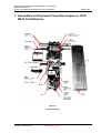
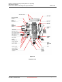
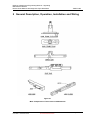
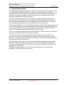
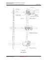
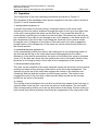
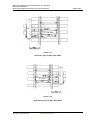
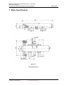
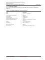
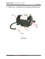
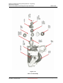
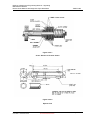
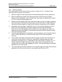
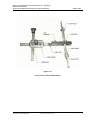
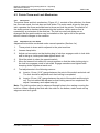
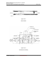
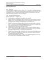
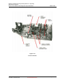
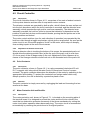
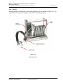
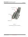
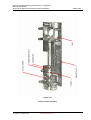
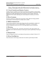
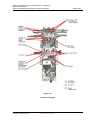
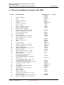
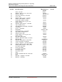
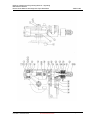
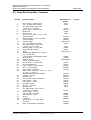
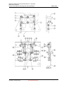
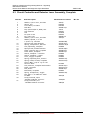
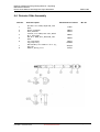
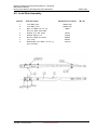
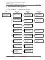
RailCorp Infrastructure Engineering Manual – Signalling Maintenance Manual Electric Point Machine Westinghouse Style M70 MKIII TMG E1583 Electric Point Machine Westinghouse Style M70 MK III TMG E1583 Owner Version 1.0 Issue Date: 1st December 2009 Chief Engineer Signals Revision Control Table Revision 1.0 Date of Approval 1/12/2009 ECP/DCN No. Summary of change First issue. Contents 1 ASSEMBLED AND EXPLODED VIEWS WESTINGHOUSE 'M70' MKIII POINT MACHINE ................................................................................................................................ 4 2 GENERAL DESCRIPTION, OPERATION, INSTALLATION AND WIRING........................ 6 2.1 GENERAL DESCRIPTION ................................................................................................ 7 2.2 OPERATION .................................................................................................................. 9 2.3 INSTALLATION ............................................................................................................. 11 2.3.1 Installation of Machine ........................................................................................ 11 2.3.2 Timber Details .................................................................................................... 12 2.3.3 Installation of Lock and Detector Slides .............................................................. 13 2.4 WIRING ...................................................................................................................... 15 3 MAJOR SPECIFICATIONS ............................................................................................. 16 3.1 4 TECHNICAL DETAILS ................................................................................................... 17 COMPONENTS – REPLACEMENT, SERVICING AND ADJUSTMENTS ....................... 18 4.1 MOTOR ...................................................................................................................... 19 4.1.1 Description ......................................................................................................... 19 4.1.2 Removal and Replacement................................................................................. 19 4.1.3 Overhaul............................................................................................................. 19 4.2 GEAR TRAIN AND CLUTCH ASSEMBLY .......................................................................... 21 4.2.1 Description ......................................................................................................... 21 4.2.2 Adjustment of Friction Clutch .............................................................................. 21 4.2.3 Overhaul of Clutch.............................................................................................. 23 4.3 POINTS THROW AND LOCK MECHANISM ....................................................................... 25 4.3.1 Description ......................................................................................................... 25 4.3.2 Adjustment of Lock Slides .................................................................................. 25 4.4 POINT DETECTOR ....................................................................................................... 27 4.4.1 Description ......................................................................................................... 27 4.4.2 Adjustment of Detector Slides............................................................................. 27 4.5 CIRCUIT CONTROLLER ................................................................................................ 29 Version 1.0 Issue Date: 1 December 2009 © RailCorp 2009 Uncontrolled when Printed Page 2 of 52 RailCorp Infrastructure Engineering Manual – Signalling Maintenance Manual Electric Point Machine Westinghouse Style M70 MKIII TMG E1583 4.5.1 Description ......................................................................................................... 29 4.5.2 Adjustment of Detector Push Rods ..................................................................... 29 4.6 POINT CONTACTOR ..................................................................................................... 29 4.6.1 Description ......................................................................................................... 29 4.6.2 Removal ............................................................................................................. 29 4.7 MOTOR PROTECTION UNIT AND RECTIFIER .................................................................... 29 4.7.1 Description ......................................................................................................... 29 4.7.2 Rectifier .............................................................................................................. 30 4.8 MANUAL CRANKING DEVICE ........................................................................................ 33 4.8.1 Description ......................................................................................................... 33 4.8.2 Adjustment of Cut-Out Switch............................................................................. 33 5 MAINTENANCE PROCEDURES .................................................................................... 34 5.1 5.2 5.3 5.4 5.5 5.6 5.7 5.8 5.9 5.10 5.11 5.12 5.13 5.14 5.15 5.16 5.17 5.18 6 PARTS LIST AND DRAWINGS....................................................................................... 39 6.1 6.2 6.3 6.4 6.5 6.6 7 GENERAL ................................................................................................................... 34 TOOLS ....................................................................................................................... 34 CHECK THAT POINT MACHINE IS SECURE ..................................................................... 34 EXAMINE TRACK CONDITIONS AT SWITCH LOCATION ..................................................... 35 ADJUST FACING POINT LOCKS (F.P.L.) ........................................................................ 35 ADJUST DETECTOR SLIDES ......................................................................................... 35 CHECK SWITCH TRAVEL .............................................................................................. 35 MOTOR MAINTENANCE ................................................................................................ 35 CIRCUIT CONTROLLER AND DETECTOR CONTACTS ....................................................... 36 POINT CONTACTOR ................................................................................................. 36 MOTOR PROTECTION UNIT ....................................................................................... 36 DRAINING ................................................................................................................ 36 ADJUST CLUTCH ...................................................................................................... 36 CLEAN POINT MACHINE ........................................................................................... 36 LUBRICATION .......................................................................................................... 38 EXCESS BALLAST .................................................................................................... 38 CHECK OPERATION OF POINT MACHINE .................................................................... 38 OVERHAUL .............................................................................................................. 38 ELECTRIC POINT MACHINE COMPLETE, ‘M70’ MKIII...................................................... 40 GEAR BOX ASSEMBLY, COMPLETE ............................................................................... 43 CIRCUIT CONTROLLER AND DETECTOR LEVER ASSEMBLY, COMPLETE ........................... 45 DETECTOR SLIDE ASSEMBLY ....................................................................................... 46 LOCK SLIDE ASSEMBLY ............................................................................................... 47 CUT-OUT SWITCH ASSEMBLY ...................................................................................... 48 DIAGNOSTIC FAULT FINDING CHARTS....................................................................... 49 7.1 FAULT FINDING CHART 1 - POINT MACHINE NOT OPERATING ......................................... 49 7.2 FAULT FINDING CHART 2 - SWITCH FAILS TO LOCK IN NORMAL OR REVERSE POSITION ... 50 7.3 FAULT FINDING CHART 3 - OPERATION OF THROW MECHANISM SLOW OR JERKY............ 51 7.4 FAULT FINDING CHART 4 - POINT MACHINE OPERATES BUT DETECTION FAILS................ 52 7.5 FAULT FINDING CHART 5 - POINT MACHINE OPERATES ONLY IN NORMAL OR REVERSE POSITION ............................................................................................................................. 53 Version 1.0 Issue Date: 1 December 2009 © RailCorp 2009 Uncontrolled when Printed Page 3 of 52 RailCorp Infrastructure Engineering Manual – Signalling Maintenance Manual Electric Point Machine Westinghouse Style M70 MKIII TMG E1583 1 Assembled and Exploded Views Westinghouse 'M70' MKIII Point Machine Figure 1.1 Assembled View Version 1.0 Issue Date: 1 December 2009 © RailCorp 2009 Uncontrolled when Printed Page 4 of 52 RailCorp Infrastructure Engineering Manual – Signalling Maintenance Manual Electric Point Machine Westinghouse Style M70 MKIII TMG E1583 Figure 1.2 Exploded View Version 1.0 Issue Date: 1 December 2009 © RailCorp 2009 Uncontrolled when Printed Page 5 of 52 RailCorp Infrastructure Engineering Manual – Signalling Maintenance Manual Electric Point Machine Westinghouse Style M70 MKIII TMG E1583 2 General Description, Operation, Installation and Wiring Figure 2.1 Main Components of Throw and Lock Mechanism Version 1.0 Issue Date: 1 December 2009 © RailCorp 2009 Uncontrolled when Printed Page 6 of 52 RailCorp Infrastructure Engineering Manual – Signalling Maintenance Manual Electric Point Machine Westinghouse Style M70 MKIII TMG E1583 2.1 General Description The Westinghouse Brake & Signal Co. "M70" Mk Ill point machine is similar in design to the McKenzie and Holland Style 'M' machines. It comprises a throw and lock mechanism driven by an electric motor, both of which are housed in a single cast iron casing. The casing also houses a motor protection unit, a circuit controller, points detection mechanism and a point contactor. The motor drives the throw and lock mechanism through a spur gear train which incorporates a friction clutch and a worm gear drive to engage the main crank. The main crank drives the throw bar and the slide bar to which the lock box is attached. The lock slides engage the lock box to positively lock the mechanism. The locking mechanism is of the 'straight through' type, with the lock slides having one notch on the top and one notch on the bottom, which engage corresponding lock dogs on each end of the lock box, ensuring that the machine cannot complete its travel unless the lock slides correspond to the position of the points. The circuit controller incorporates motor and detection contacts, which check that the points are closed and locked in their correct position. The motor protection unit is located near the motor and the point controller. For protection of the motor, the motor circuit is switched off automatically by the motor protection unit when operation takes abnormally long. The point contactor determines the switching direction of the motor. A heavy gauge sheet steel cover with a moulded neoprene gasket provides ample protection and a granulated cork coating on the inside crank inhibits condensation. The cover, which is hinged at one end, can be removed completely and has a hasp and staple for padlocking. Emergency manual operation is achieved by inserting a hand crank through a separately covered hole in the main cover. Version 1.0 Issue Date: 1 December 2009 © RailCorp 2009 Uncontrolled when Printed Page 7 of 52 RailCorp Infrastructure Engineering Manual – Signalling Maintenance Manual Electric Point Machine Westinghouse Style M70 MKIII TMG E1583 Figure 2.2 Main Operation Version 1.0 Issue Date: 1 December 2009 © RailCorp 2009 Uncontrolled when Printed Page 8 of 52 RailCorp Infrastructure Engineering Manual – Signalling Maintenance Manual Electric Point Machine Westinghouse Style M70 MKIII TMG E1583 2.2 Operation The components of the main operating mechanism are shown in Figure 2.1. The operation of the mechanism when power is applied to the main crank is shown in Figure 2.2 and is described below: 1. Normal position (Figure 2.2-1) A reverse movement is commenced by a clockwise rotation of the main crank. Unlocking of the lock slide is achieved through the action of the lug on the upper side of the main crank against the rollers on the slide bar. This causes the slide bar to move thereby unlocking the lock box from the lock slide. Simultaneously, the roller on the underside of the crank moves through an arc of 40 degrees in the radial section of the escapement of the throw bar, thus freeing the throw bar for the reverse stroke. During the next 140 degrees of revolution of the main crank, the roller engages the straight section of the escapement of the throw bar, which moves the throw bar into the reverse position. 2. Intermediate Position (Figure 2.2-2) At the intermediate position the crank is still rotating but is not transmitting motion to the slide bar as the lug on the crank has become disengaged from the rollers. Movement of the slide is prevented by the action of the ends of the crank on surfaces X and Y of the slide bar, which are now radial to the centre of the shaft. Motion of the throw bar is occurring by action of the roller on the escapement of the throw bar. 3. Reverse Position (Figure 2.2-3) The roller on the underside of the main crank has thrown the throw bar into the reverse position and secured it by entering radial section of the throw bar escapement. The opposite lug at the top of the crank has engaged the rollers on the slide bar and moved the slide bar and the lock box into the reverse position. The lock box has engaged the notch in the lock slide, which has also been moved into the reverse position by the action of the points. 4. Locking The locking of the lock slides in the lock box is achieved by means of two lock dogs in opposite ends of the lock box, one at the top and one at the bottom. The lock slides have corresponding notches cut in the top and bottom of the slides. Positive locking in both normal and reverse positions is achieved by engagement of the dog in the notch. Version 1.0 Issue Date: 1 December 2009 © RailCorp 2009 Uncontrolled when Printed Page 9 of 52 RailCorp Infrastructure Engineering Manual – Signalling Maintenance Manual Electric Point Machine Westinghouse Style M70 MKIII TMG E1583 Figure 2.3.1 Left Hand Layout of Style ‘M70’ MKIII Figure 2.3.2 Right Hand Layout of Style ‘M70’ MKIII Version 1.0 Issue Date: 1 December 2009 © RailCorp 2009 Uncontrolled when Printed Page 10 of 52 RailCorp Infrastructure Engineering Manual – Signalling Maintenance Manual Electric Point Machine Westinghouse Style M70 MKIII TMG E1583 2.3 Installation The right and left hand layouts of the M70 MKIII point machine are illustrated in Figures 2.3.1 and 2.3.2. For complete details of layouts refer to "Switch and Detail Layouts — Power Operation Book" (SRA publication). 2.3.1 (a) Installation of Machine Preparation Instructions The following instructions outline the necessary preparation prior to installation of the point machine. 1. Ballasting, tamping and alignment of track to be completed by the civil maintainer. 2. Excess ballast is to be removed to allow free movement of switches and connecting rods. Particular attention should be given to small particles of ballast under the switches. This will be evident when the switches are moved back and forth. 3. Check that heel blocks (if fitted), studs at each chair and all rail fastenings are secure. 4. Check that switches are square at point of switches. 5. Move each switch independently and check that they bear evenly on each chair A, B, C, D. 6. Each switch should move freely and fit evenly against the stock rail without undue force. 7. Any defects regarding the above steps should be brought to the attention of the civil maintainer. NOTE: When operating points by hand prior to connection of the points machine the same effort should apply to both normal and reverse position. (b) Installation Procedure 1. Fit front rod. 2. Fit back rod. 3. Fit additional back rods 3rd and 4th if required depending on switch length. 4. Fit cradle to front rod. 5. Fit extension pieces to N and R switches. 6. Fit lock rod. 7. Adjust point opening to 115mm (4 1/2"). 8. Bar points to both normal and reverse and ensure they bear evenly on the stock rails without having to exert undue pressure. 9. Fit tie plates to rail brace chairs on scarfed timbers (note insulation to be provided). Version 1.0 Issue Date: 1 December 2009 © RailCorp 2009 Uncontrolled when Printed Page 11 of 52 RailCorp Infrastructure Engineering Manual – Signalling Maintenance Manual Electric Point Machine Westinghouse Style M70 MKIII TMG E1583 10. Fit and align switch machines on tie plates. 11. Drill 4 x 21mm holes through tie plates and scarfed timber. 12. Fit switch machine using specified hexagon bolts with headlock washers underneath, round and spring washer on top. 13. Assemble lock and detector slides to machine as described in Section 2.3.3 A and B. 14. Fit point driving rod with bobbins to cradle and throw bar of machine. 15. Crank machine both to normal and reverse positions, and adjust spring on points. Note: Excessive spring should be avoided. 16. Fit lock driving rod and adjust normal and reverse facing point locks according to Section 4.3.3. 17. Fit normal and reverse detector rods, note that sleeve bearings must be used on each rod. 18. Adjust detector slides according to Section 4.4.2. Check that all fittings, lock nuts on switch connections, and adjustments are correct. Points are now ready for power operation and are to be tested for correct operation using manual cranking. 21. When all connections and adjustments have been made, track movement and heel condition should be observed under traffic and any problems brought to the attention of the civil maintainer. 22. Forty eight hours after installation, the points adjustment must again be checked and the operation observed under traffic to ensure that no settling of the track has occurred. 2.3.2 Timber Details The details of the timbers on which the machine is mounted are shown in Figure 2.3.2. Figure 2.3.2 Mounting Timber Details Version 1.0 Issue Date: 1 December 2009 © RailCorp 2009 Uncontrolled when Printed Page 12 of 52 RailCorp Infrastructure Engineering Manual – Signalling Maintenance Manual Electric Point Machine Westinghouse Style M70 MKIII 2.3.3 TMG E1583 Installation of Lock and Detector Slides A Installation of Lock Slides 1. Assemble lock slides with serrations together. 2. Using manual operation, throw the switch to the mid-stroke position. 3. Insert slides into machine so that serrations are on left hand side of machine viewed from detector end and the bar with long set of serrations facing towards same end of the machine. 4. Fit drop lug to appropriate end of bar and connect to points. 5. Adjust lock slides according to Section 4.3.2. B Installation of Detector Slides 1. Insert detector slides into machine with long threaded end for drop lug towards points. 2. Connect to points and adjust according to Section 4.4.2. Version 1.0 Issue Date: 1 December 2009 © RailCorp 2009 Uncontrolled when Printed Page 13 of 52 RailCorp Infrastructure Engineering Manual – Signalling Maintenance Manual Electric Point Machine Westinghouse Style M70 MKIII TMG E1583 Figure 2.4 Internal Wiring Diagram ‘M70’ MKIII Version 1.0 Issue Date: 1 December 2009 © RailCorp 2009 Uncontrolled when Printed Page 14 of 52 RailCorp Infrastructure Engineering Manual – Signalling Maintenance Manual Electric Point Machine Westinghouse Style M70 MKIII TMG E1583 2.4 Wiring The internal wiring is in high temperature PVC insulated wire, 50/02.mm (70/.0076) for motor circuits and 30/0.2mm (40/.0076) for control and detection circuits. Wiring between the terminal board and the circuit controller is protected by a rigid PVC conduit. A 51 mm (inside diameter) flexible conduit connection is provided near the terminal board for incoming wires. The point machines are wired to short-circuit the detection relay(s) while the detection is open. If this is not required, remove the three links between 9-8 and 9-4, 9-4 and 8 3, 8-3 and 8-7 on the detector switches. The internal wiring diagram for the point machine is given in Figure 2.4. Version 1.0 Issue Date: 1 December 2009 © RailCorp 2009 Uncontrolled when Printed Page 15 of 52 RailCorp Infrastructure Engineering Manual – Signalling Maintenance Manual Electric Point Machine Westinghouse Style M70 MKIII TMG E1583 3 Major Specifications Figure 3.1 Overall Dimensions Version 1.0 Issue Date: 1 December 2009 © RailCorp 2009 Uncontrolled when Printed Page 16 of 52 RailCorp Infrastructure Engineering Manual – Signalling Maintenance Manual Electric Point Machine Westinghouse Style M70 MKIII TMG E1583 3.1 Technical Details The technical information describing the 'M70' MKIII point machine is tabulated in Table 3.1. Table 3.1 M70 MKIII Point Machine Technical Information Item Description Motor 110V, D.C., Split Field Point Controller Thrust Rated 50V, D.C. Thrust Rated 3000N Approx. Thrust Maximum 4500N Approx. Gear Box Ratio Operating Time 112:1 Ambient Temperature Range 4 Seconds at rated voltage - 10 to 60 degree C. Weight 214 kg. approximately Dimensions Refer to Figure 3.1. Motor Protection Unit 50V D.C Cut-off Time 10 seconds (+25% -25%) ± 25% Version 1.0 Issue Date: 1 December 2009 © RailCorp 2009 Uncontrolled when Printed Page 17 of 52 RailCorp Infrastructure Engineering Manual – Signalling Maintenance Manual Electric Point Machine Westinghouse Style M70 MKIII TMG E1583 4 Components – Replacement, Servicing and Adjustments Figure 4.1.1 Motor M70 MKIII Version 1.0 Issue Date: 1 December 2009 © RailCorp 2009 Uncontrolled when Printed Page 18 of 52 RailCorp Infrastructure Engineering Manual – Signalling Maintenance Manual Electric Point Machine Westinghouse Style M70 MKIII TMG E1583 4.1 Motor 4.1.1 Description The point machine is fitted with a plug-connected series-wound motor, as shown in Figure 4.1.1. The split field enables a regenerative braking circuit to provide snubbing at the end of the stroke. The plug connector is indexed to prevent use of a wrong type motor. If required, the machine can also be fitted with a 110V DC, AC immune permanent magnet motor. 4.1.2 Removal and Replacement 1. Unplug the lead from the terminal board. 2. Remove the two bolts from the baseplate. 3. Slide the motor towards the end of the machine until the spur gear disengages from the gear cluster and then remove the motor. 4. Replacement involves the above procedures in reverse order. Care should be taken to ensure that the spur gear meshes properly and that the location spigot seats properly before bolting down. 4.1.3 Overhaul The operation of the motor should be observed during normal monthly maintenance visits. If it shows signs of abnormal noise, slackness in the bearings or heavy burning of the commutator, the motor should be exchanged. Version 1.0 Issue Date: 1 December 2009 © RailCorp 2009 Uncontrolled when Printed Page 19 of 52 RailCorp Infrastructure Engineering Manual – Signalling Maintenance Manual Electric Point Machine Westinghouse Style M70 MKIII TMG E1583 Figure 4.2.1 Gear Train Assembly Version 1.0 Issue Date: 1 December 2009 © RailCorp 2009 Uncontrolled when Printed Page 20 of 52 RailCorp Infrastructure Engineering Manual – Signalling Maintenance Manual Electric Point Machine Westinghouse Style M70 MKIII TMG E1583 4.2 Gear Train and Clutch Assembly 4.2.1 Description The motor drives a spur gear train, which in turn drives a worm through a friction clutch. The worm engages the main gear, which drives the lock and throw mechanism. The clutch protects the mechanism from shock at the end of the movement and also when the points are obstructed. The worm shaft is also engaged by a bevel gear driven by a shaft, which engages the manual crank handle. 4.2.2 Adjustment of Friction Clutch Before leaving the manufacturer, the friction clutch is adjusted for greater than average point loads. This adjustment should adequately allow any high point loads, which may be encountered during the machine's operation. However the clutch must be tested on completion of installation. Re-adjustment may be necessary during the maintenance visit and conducted in the following manner. To Test Clutch 1. Connect an ammeter in series with the motor circuit, and measure the normal operating current. 2. Insert a block of wood or similar between the switch and the stock rail so as to obstruct the operation of the switch. 3. Operate the switch machine, and measure the obstruction current. The clutch should slip at approximately 150% of the normal operating current. To Adjust Clutch 1. Remove supply from the motor by removing circuit fuses. 2. Remove split pin from clutch adjusting nut. 3. Tighten clutch adjusting nut, replace split pin and re-test. Repeat items 1-3 as required until the correct adjustment is achieved. NOTE: Clutch slippage may be caused by worn clutch discs or by fouling of the clutch discs with lubricant from the gear train due to ineffective packing between the clutch shaft and housing (see Section 4.2.3). Version 1.0 Issue Date: 1 December 2009 © RailCorp 2009 Uncontrolled when Printed Page 21 of 52 RailCorp Infrastructure Engineering Manual – Signalling Maintenance Manual Electric Point Machine Westinghouse Style M70 MKIII TMG E1583 Figure 4.2.3.1 Cross -Section of Friction Clutch Figure 4.2.3.2 Special Tool Version 1.0 Issue Date: 1 December 2009 © RailCorp 2009 Uncontrolled when Printed Page 22 of 52 RailCorp Infrastructure Engineering Manual – Signalling Maintenance Manual Electric Point Machine Westinghouse Style M70 MKIII 4.2.3 TMG E1583 Overhaul of Clutch The cross-section of the friction clutch is shown in Figure 4.2.3.1. Overhaul of the clutch should be carried out as follows: 1. Measure length of clutch spring before dis-assembling and note this dimension. 2. Remove adjusting nut and clutch spring and slide clutch housing off shaft. Remove discs and plates, take out small lock screw and use special tool (Figure 4.2.3.2) to remove packing gland nut. 3. Remove old felt packing and clean shaft and inside of clutch housing by washing with chlorothene. After parts are thoroughly cleaned and dried, a light coating of lubricant should be applied to shaft at point where new packing is to be applied. 4. Assemble clutch housing on shaft with end of clutch housing meshed in hub of gear. One new felt packing, should be slipped over the shaft and tamped securely into the packing gland with the plain end of the special tool. After first packing has been assembled. A second felt packing should be inserted in same manner and tamped down. 5. Insert the packing gland nut and tighten using the spanner end of special wrench until it is flush with bottom of clutch housing. Insert lock screw and tighten securely. 6. Clutch plates and fabric discs should be thoroughly cleaned with chlorothene to remove any accumulation of lubricant, inspected for damage and wear and replaced if necessary prior to reassembly in the order shown in Figure 4.2.3.1. It will be noted that a fabric disc goes in the bottom of the housing and the first metallic disc is one with teeth engaging the shaft. The remaining discs and plates assemble in the order shown. 7. The clutch spring should be adjusted to its original length and finally checked and adjusted to the correct slip current in accordance with Section 4.2.2. Version 1.0 Issue Date: 1 December 2009 © RailCorp 2009 Uncontrolled when Printed Page 23 of 52 RailCorp Infrastructure Engineering Manual – Signalling Maintenance Manual Electric Point Machine Westinghouse Style M70 MKIII TMG E1583 Figure 4.3.1 Point’s Throw and Lock Mechanism Version 1.0 Issue Date: 1 December 2009 © RailCorp 2009 Uncontrolled when Printed Page 24 of 52 RailCorp Infrastructure Engineering Manual – Signalling Maintenance Manual Electric Point Machine Westinghouse Style M70 MKIII TMG E1583 4.3 Points Throw and Lock Mechanism 4.3.1 Description The points throw and lock mechanism, Figure 4.3.1, consists of the slide bar, the throw bar, the main crank, the lock box and lock slides. The main crank, driven by the gear train, operates the throw and slide bars to throw and lock the points. The position of the switch points is checked and secured by the lock box, which rests on and is operated by an extension of the slide bar. The lock box and lock slides are so arranged that the point machine may be installed on the right or left of the points without internal changes to the machine. 4.3.2 Adjustment of Lock Slides Adjustment should be conducted under manual operation (Section 4.e). 1. Throw points to close switch adjacent to the point machine. 2. Loosen clamp bolts. 3. Adjust rod connection so that locking dog in lock box engages notch in lock slide and in doing so, holds point blade against stock rail. 4. Wind the points to close the opposite switch. 5. Move the second lock slide into correct position so that the other locking dog in the lock box engages notch in lock slide. Engage serrations and tighten bolts clamping slides together at each end. 6. Test adjustments in the following manner: (a) Insert a 1.6mm (1/16") gauge between the point of the switch and stock rail. The lock should be adjusted such that locking is completed. (b) Insert a 3.2mm (1/8") gauge between the point of the switch and the stock rail. The lock should be adjusted so that locking cannot be completed. Re adjust if necessary and repeat step (a). Note: The locking action may be observed through holes in the casting covering the lock box. When adjusting the slide with the notch on the bottom, marks made on top edge are used as a guide. Version 1.0 Issue Date: 1 December 2009 © RailCorp 2009 Uncontrolled when Printed Page 25 of 52 RailCorp Infrastructure Engineering Manual – Signalling Maintenance Manual Electric Point Machine Westinghouse Style M70 MKIII TMG E1583 Figure 4.4.1.1 Detector Rods Figure 4.4.1.2 Point Detector Assembly Version 1.0 Issue Date: 1 December 2009 © RailCorp 2009 Uncontrolled when Printed Page 26 of 52 RailCorp Infrastructure Engineering Manual – Signalling Maintenance Manual Electric Point Machine Westinghouse Style M70 MKIII TMG E1583 4.4 Point Detector 4.4.1 Description The point detector assembly, shown in Figure 4.4.1.2, consists of rod shaped detector slides, Figure 4.4.1.1, which mechanically determine the position of the switches. The mechanical movement is transferred through a detector lever assembly to open and close the required contacts on the circuit controller. TAPERED FACE 4.4.2 Adjustment of Detector Slides (Refer to Figures 4.4.1.1 and 4.4.1.2). 1. Crank machine to close switch furthest from the machine. 2. Adjust connecting rod of detector slide connected to the closed switch so that the detector roller, in contact with this detector slide and nearest to the points, is just touching the small diameter and tapered face of the detector rod. 3. Adjust connecting rod of detector slide connected to the open switch so that the roller, in contact with this detector slide and nearest to the points, is resting in the small diameter and about 3 mm clear of the tapered face. 4. Crank machine to close switch nearest machine. 5. Adjust sleeve of detector rod connected to the open switch so that the detector roller, in contact with this slide and furthest from the points is resting in the small diameter and approximately 3 mm clear of the tapered face. 6. Adjust sleeve of detector slide connected to the closed switch so that the detector roller, in contact with this slide and furthest from the points is just touching both the small diameter and tapered face. 7. Check the adjustment by using a 3.2mm (1 /8") facing point gauge to check that the contacts are just made at 3.2mm switch opening. Version 1.0 Issue Date: 1 December 2009 © RailCorp 2009 Uncontrolled when Printed Page 27 of 52 RailCorp Infrastructure Engineering Manual – Signalling Maintenance Manual Electric Point Machine Westinghouse Style M70 MKIII TMG E1583 Figure 4.5.1 Circuit Controller Version 1.0 Issue Date: 1 December 2009 © RailCorp 2009 Uncontrolled when Printed Page 28 of 52 RailCorp Infrastructure Engineering Manual – Signalling Maintenance Manual Electric Point Machine Westinghouse Style M70 MKIII TMG E1583 4.5 Circuit Controller 4.5.1 Description The circuit controller shown in Figure 4.5.1, comprises of two sets of sealed contacts for the points detector and two sets of snap action motor contacts. The detector contacts are operated by both a roller, which follows the cam surface cut into the lock box above which the circuit controller is mounted, and the detector lever assembly, which operates through a roller, and lever assembly. The detector lever assembly overrides the lock box roller to ensure that detection is dependent on the position of both the lock box and the switch blades, proving that the points are in the correct position and locked. The motor control switches (one for each direction of operation) are operated by the lock box roller through a toggle mechanism, which gives a snap action. As soon as the motor circuit is cut, the switch applies a "snub" to the motor, which stops it abruptly, thus avoiding impact at the end of the traverse. 4.5.2 Adjustment of Detector Push Rods When a detector roller is touching the bottom of its recess, the associated push-rod should allow the detector switch roller (at the far end of the push- rod) to rest clear (10.4 mm max) of the 45 degree step in the rod. Adjustment of this clearance is by means of the hexagon domed nut and lock nut on the threaded end of the push-rod. 4.6 4.6.1 Point Contactor Description The point contactor, shown in Figure 4.6.1, is a plug-connected interlocked 50 volt D.C. magnetic stick relay which actuates 3 sets of normal and 3 sets of reverse contacts. The point contactor determines the direction of the motor by switching to the appropriate field winding. To protect the contacts from foreign matter which may disrupt operation, the unit is sealed by a protective plastic cover. 4.6.2 Removal The point contactor is simply removed by unplugging the lead and loosening the two screws at the base. 4.7 4.7.1 Motor Protection Unit and Rectifier Description The motor protection unit, shown in Figure 4.7.1, is located on the mounting plate of the terminal board. It is designed to protect the motor and the friction clutch in the event that an obstruction prevents movement of the throw mechanism by cutting the motor circuit when operation takes abnormally long. The motor circuit is reconnected automatically by restoring the points lever to its original position. Version 1.0 Issue Date: 1 December 2009 © RailCorp 2009 Uncontrolled when Printed Page 29 of 52 RailCorp Infrastructure Engineering Manual – Signalling Maintenance Manual Electric Point Machine Westinghouse Style M70 MKIII 4.7.2 TMG E1583 Rectifier A bridge rectifier is fitted next to the motor protection unit, as shown in Figure 4.7.1, to convert the incoming A.G. supply current to D.C. operating current. Figure 4.6.1 Point Contactor Version 1.0 Issue Date: 1 December 2009 © RailCorp 2009 Uncontrolled when Printed Page 30 of 52 RailCorp Infrastructure Engineering Manual – Signalling Maintenance Manual Electric Point Machine Westinghouse Style M70 MKIII TMG E1583 Figure 4.7.1 Terminal Board, Motor Protection Unit and Rectifier Version 1.0 Issue Date: 1 December 2009 © RailCorp 2009 Uncontrolled when Printed Page 31 of 52 RailCorp Infrastructure Engineering Manual – Signalling Maintenance Manual Electric Point Machine Westinghouse Style M70 MKIII TMG E1583 Figure 4.8.1 Cut-Out Switch Assembly Version 1.0 Issue Date: 1 December 2009 © RailCorp 2009 Uncontrolled when Printed Page 32 of 52 RailCorp Infrastructure Engineering Manual – Signalling Maintenance Manual Electric Point Machine Westinghouse Style M70 MKIII TMG E1583 4.8 Manual Cranking Device 4.8.1 Description Manual operation is obtained by inserting a crank handle through a separately covered hole in the cover of the machine. Opening of the cap on the cover reveals the yoke of the cut-out mechanism, shown in Figure 4.8.1. Pushing the yoke across allows the crank handle to be inserted onto the cut-out spindle and simultaneously opens the cut out switch through an extended shaft to disconnect the motor. Removal of the crank handle re-closes the cut-out switch and restores the motor circuit. 4.8.2 Adjustment of Cut-Out Switch Adjustment is achieved by the adjusting bolt as shown in Figure 4.8.1. The bolt should be adjusted so that it just touches the plunger of the cut-out switch when the yoke is in its normal position. Version 1.0 Issue Date: 1 December 2009 © RailCorp 2009 Uncontrolled when Printed Page 33 of 52 RailCorp Infrastructure Engineering Manual – Signalling Maintenance Manual Electric Point Machine Westinghouse Style M70 MKIII TMG E1583 5 Maintenance Procedures 5.1 General Before commencing, notify the signalman and carry out normal safeworking procedures. All PPE applying to personnel working on or near the track must be observed. Whenever possible the maintenance activities of the Signal Electrician and the Signal Sectionman should be performed simultaneously. 5.2 Tools Description Size Quantity BACHO adjustable spanner 18" (450mm) 2 BACHO adjustable spanner 15" (375mm) 2 BACHO adjustable spanner 12" (300mm) 2 Screwdriver 8" (200mm) 1 Chisel (cold) 1 Podger (claw type) 1 F.P.L. gauge 1/8" (3.2mm) 1 F.P.L. gauge 1/16" (1.6mm) 1 Whitworth, A.F. and metric socket sets with drive extension and ratchet 1 set 1 set Whitworth, A.F. and metric ring spanners Relay spanner 1 Crank handle 1 Vernier Calipers 1 Special tool for clutch overhaul 1 Check also that the kit includes consumables such as chamois leather, cotton waste, emery cloth, and lubricants. 5.3 Check that Point Machine is Secure Holding down bolts should be checked for security and tightness. Check for lost motion in switch connections, point slides, lock slides and detector rods. Version 1.0 Issue Date: 1 December 2009 © RailCorp 2009 Uncontrolled when Printed Page 34 of 52 RailCorp Infrastructure Engineering Manual – Signalling Maintenance Manual Electric Point Machine Westinghouse Style M70 MKIII TMG E1583 5.4 Examine Track Conditions at Switch Location Examine track in respect to ballast condition and rail movement at switch heel, fit of switch to stock rail, condition of chairs, bolts and spikes. If lateral or longitudinal movement is detected, notify the civil maintainer for rectification. 5.5 Adjust Facing Point Locks (F.P.L.) Facing point locks must be tested to ensure that the switches are kept tight against the running face of the stock rail, and to ascertain if "A" chairs or stock rails are worn. The following steps should be conducted under manual operation: (i) Adjust lock slides in accordance with procedures outlined in Section 4.3.2. (ii) Test adjustments in the following manner: (a) Insert a 1.6mm (1.16") gauge between the point of the switch and stock rail. The lock should be adjusted such that locking is completed. (b) Insert a 3.2mm (1 /8") gauge between the point of the switch and the stock rail. The lock should be adjusted so that locking cannot be completed. Re adjust if necessary and repeat step (a). 5.6 Adjust Detector Slides Adjust detector slides in accordance with procedures outlined in Section 4.4.2. and ensure that contacts are just made with the 3.2mm gauge inserted between switch and stock rail. 5.7 Check Switch Travel Ensure that travel at the point of the switch is correct at 115mm. 5.8 Motor Maintenance The motor is equipped with sealed ball bearings which eliminates the need for lubrication. The operation of the motor should be observed at each maintenance visit. If it shows signs of abnormal noise, slackness in the bearings or heavy burning of the commutator, the motor should be exchanged and forwarded to the workshops for over haul. If the motor is operating properly, the only maintenance required is as follows: a) Check the wear on the brushes and replace them if necessary. Do NOT interchange the brushes. Brushes should not be removed unless absolutely necessary. If they are removed, care should be taken to ensure that brushes are replaced in the same positions as they were in prior to removal. b) If the commutator has a polished bronze or coffee-coloured finish leave untouched. Otherwise clean carbon dust off the commutator and brushes and clean the commutator with a chamois. Do not use emery paper to clean the commutator. If commutator is burnt, clean with fine glass paper and polish with a chamois. c) Check that the brushes slide freely in their holders. d) Check by observing the motor in operation that the brushes are seating over the full width. (Poor seating is evidenced by uneven arcing.) If they are not, hold a Version 1.0 Issue Date: 1 December 2009 © RailCorp 2009 Uncontrolled when Printed Page 35 of 52 RailCorp Infrastructure Engineering Manual – Signalling Maintenance Manual Electric Point Machine Westinghouse Style M70 MKIII TMG E1583 25mm x 150mm strip of emery cloth tightly around the commutator, face out wards and rotate against the brush in both directions until seating is improved. 5.9 Circuit Controller and Detector Contacts Visually check the condition of all contacts and observe the operation of each contact assembly ensuring adequate wipe of the contacts as the machine is operated by hand. Replace any contact assemblies which have pitted or burnt contacts. Check the adjustment of the contact assembly push rod and adjust if necessary as in Section 4.5.2. 5.10 Point Contactor The point contactor is a sealed unit and must be closely observed during operation and changed if contacts appear to be badly burnt or pitted. 5.11 Motor Protection Unit Test the motor protection unit by obstructing points with a wood block or similar and ensure that the motor is cut off in approximately 10 seconds. If it is less than 7 seconds temporarily wire the unit out of circuit and replace as soon as practical. 5.12 Draining During each maintenance visit, remove the 9.5mm B.S.P. drain plug (located in the crankcase cover under the machine) for draining the machine, particularly if freezing is likely. 5.13 Adjust Clutch Check and adjust the clutch in accordance with procedures outlined in Section 4.2.2. 5.14 Clean Point Machine Clean all excess oil and foreign matter from the machine, particularly the slides. Version 1.0 Issue Date: 1 December 2009 © RailCorp 2009 Uncontrolled when Printed Page 36 of 52 RailCorp Infrastructure Engineering Manual – Signalling Maintenance Manual Electric Point Machine Westinghouse Style M70 MKIII TMG E1583 Figure 5.15 Lubrication Diagram Version 1.0 Issue Date: 1 December 2009 © RailCorp 2009 Uncontrolled when Printed Page 37 of 52 RailCorp Infrastructure Engineering Manual – Signalling Maintenance Manual Electric Point Machine Westinghouse Style M70 MKIII TMG E1583 5.15 Lubrication Remove the covers to the machine and lubricate all moving parts as indicated on the Lubrication Diagram 5.15 and with lubricants specified in Table 5.15. Table 5.15 Lubrication Parts Lubricants Remarks Small pins and sliding parts marked "0". Oil SAE – 30 Clean the parts well before applying. Surplus oil should be wiped off as it attracts dust Medium and heavy load bearings marked “G” Grease, multi-purpose Lithium Based, M1 26843151 Use a grease gun for lubrication Sliding surfaces detector, lock slides and throw bar, gear teeth marked “M” Molybond GA10 Grease Apply sparingly by brush after cleaning off build up Points to be observed while carrying out lubrication: 1. Use only the recommended grade of oil. Inferior grades should be avoided as they may cause rust, material fatigue or blockage in oil holes. 2. On locations of light pin movement, only a few drops of oil are required. 3. Use brushes to grease gear surface where heavy weight is applied. 4. Supply a thin layer of oil on all sliding surfaces and at times wipe with an oil cloth to remove accumulated grit. 5. The slide chairs must be cleaned and lubricated with an approved dry lubricant at each maintenance visit by the maintainer. 5.16 Excess Ballast Clear all ballast and foreign matter likely to foul the operation of the point machine to ensure clearance around all moving parts of the points. 5.17 Check Operation of Point Machine Check smoothness and correctness of operation by switching several times using manual operation, and finally by power operation. 5.18 Overhaul A fixed overhaul period cannot be set due to traffic movement frequencies and local conditions. Overhaul periods must be determined by inspection during maintenance, to determine the amount of wear on the gears, throw bar, lock slide bearing surfaces and the general condition of the mechanism. General overhaul involves complete stripping, cleaning and inspection, replacement of worn and faulty parts and reassembly as discussed in appropriate sections of this manual. Version 1.0 Issue Date: 1 December 2009 © RailCorp 2009 Uncontrolled when Printed Page 38 of 52 RailCorp Infrastructure Engineering Manual – Signalling Maintenance Manual Electric Point Machine Westinghouse Style M70 MKIII TMG E1583 6 Parts List and Drawings Version 1.0 Issue Date: 1 December 2009 © RailCorp 2009 Uncontrolled when Printed Page 39 of 52 RailCorp Infrastructure Engineering Manual – Signalling Maintenance Manual Electric Point Machine Westinghouse Style M70 MKIII TMG E1583 6.1 Electric Point Machine Complete, ‘M70’ MKIII Item No. 1 2 3 4 5 6 7 8 9 10 11 12 Item Description Manufacturer's Part No. 17 18 Cover, Complete Stud Roller — 2 in. Dia. Roller — 1 3/4 in. Dia. Lock Box Cover — Crankcase Crank — Main Bar — Slide with connector Block — Terminal, 4 Way Detector Slide, Complete Detector Lever Assembly (Double) Bolt, 3/8 in. B.S.W. x 1 1/4 in Lg. Hex. Hd. Steel Tin Plate Hood, Lock Slide Lug, Throw Bar Washer, Spring 3/16 in. Tin Plate Screw, 2BA x 3/8 in. Lg. Ch. Hd. Steel, Tin Plate Washer, Plain 3/16 in. Base 19 Tube, Insulating 20 21 22 23 24 25 26 Terminal, Chassis. Cu. Tin Plate Motor Protection Unit — 50 V dc Nut Nyloc. 2BA Steel Washer, 2BA, Plain, Brass, Tin Plate Rectifier, S10 PFA Washer, Spring, 3/16 in. Tin Plate Screw, 2BA x 3/8 in. 1g. Ch. Hd.y Steel, Tin Plate Screw, 3/8 in. BSW x 3/4 in. Lg. Hex. Hd. Steel, Tin Plate Conduit, outlet 'ELMACO' , 'ELMACO Cat. No. 161' Hasp and Staple, Safety Type 6 1/2 in. `McPHERSONS Cat. No. F1607' Bracket, Contactor Mounting, AC Immune Contactor, Complete, 50Vdc Clip, Spring Tab. Housing 'AMP No. 480171-1' Receptacle Screw, 4BA x 1/4 in. Lg. Ch. Hd. Steel, Tin Plate Rivet, Pop. 1/8 in. Washer, Star, 3/8 in. Screw, 3/8 in., UNC X 3/4 in. Lg. Hex. Hd. Steel, Tin Plate Motor, Complete, 110 Vdc Series Wound Bolt, 3/8 in. BSW x 2 ins. Lg. Hex. Hd. 13 14 15 16 27 28 29 30 31 32 33 34 35 36 37 38 39 40 Version 1.0 Issue Date: 1 December 2009 © RailCorp 2009 Uncontrolled when Printed M.I. No. M20750 M20461 M7624 M7625 CM267-27/2 146290 71158 146444 181829 M23930 M6800 M20548 146443 4024/10 M2103 4023/14 M20484 AM4811 33/2 BM510-54/1 M23832 4254/30 17376 4940/10 4024/10 M2103 4166/23 4467/137 4742/15 M23471 M23856 AM3879-59/1 4036/87 4036/176 M2328 4745/0 4025/0 4166/52 M23805 Page 40 of 52 RailCorp Infrastructure Engineering Manual – Signalling Maintenance Manual Electric Point Machine Westinghouse Style M70 MKIII Item No. 41 42 43 44 45 46 47 48 49 50 51 52 53 54 55 56 57 58 59 60 61 62 63 64 65 66 67 68 69 70 71 72 73 74 Item Description TMG E1583 Manufacturer's Part No. Steel, Tin Plate Washer, Spring, 3/8 in. Cad. Plate Washer, Special Gear Box Assembly, Complete Cover, Gear M6797 4024/16 AM1780-89/1 M23834 M21879 Washer, Spring 1/2 in., Tin Plate Screw, 1/2 in. BSW x 1 1/2 in. Socket Hd., Steel, Tin Plate Screw, 2BA x 3/8 in. Lg. Ch. Hd. Steel Tin Plate Washer, Spring 3/16 in., Tin Plate Clip, Conduit, 3/4 in. Cut-Out Switch Assembly, Complete Throw Bar Hood — Throw Bar Nameplate Screw, Drive No. 4, Tin Plate Clip, Cable, `Plaskip No. 6' Washer, Plain, 4BA Screw, 4BA x 1/4 in. Lg. Ch. Hd. Steel Tin Plate Nut, Nyloc, 2BA. Steel Washer, 2BA Plain, Brass, Tin Plate Bolt, Special Washer, Spring 3/8 in. Cad. Plate Circuit Controller, Complete Cover, complete — Circuit Controller Washer, Spring, 3/8 in. Cad. Plate Screw, 3/8 in. B.S.W. x 1/2 Lg. Hex. Hd. Steel, Cad. Plate Hood, Lock Slide Lock Slide, Complete Pin-Hinge, Long Pin-Hinge, Short Stud Circlip, 'TRUARC Ref. No. 5100-162' Bush Bracket — Support, Lock Rod Bracket — Wearing 4024/3 Version 1.0 Issue Date: 1 December 2009 © RailCorp 2009 Uncontrolled when Printed M.I. No. 4155/1 M2101 4024/10 4407/78 M23837 146441 148141 AM4881-325/1 4091/11 4023/15 M2328 4254/30 17376 AM7598-43/1 4024/16 M23835 M23840 4024/16 4166/25 M20548 M21103 M21097 M21368 4484/93 AM426-117/1 M16969 189024 Page 41 of 52 RailCorp Infrastructure Engineering Manual – Signalling Maintenance Manual Electric Point Machine Westinghouse Style M70 MKIII Version 1.0 Issue Date: 1 December 2009 © RailCorp 2009 Uncontrolled when Printed TMG E1583 Page 42 of 52 RailCorp Infrastructure Engineering Manual – Signalling Maintenance Manual Electric Point Machine Westinghouse Style M70 MKIII TMG E1583 6.2 Gear Box Assembly, Complete Item No. 1 2 3 4 5 6 7 8 9 10 11 12 13 14 15 16 17 18 19 20 21 22 23 24 25 26 27 28 29 30 31 32 33 34 35 36 37 38 39 40 Item Description Manufacturer's Part No. Bush, Upper — Main Crank Nut, 1 in. BSW Hex. Slotted Pin, Split Cotter 3/16 in. Dia x 1 5/8 in. Lg. Tin Plate Bush, Lower — Main Crank Main Crank Worm Wheel Screw, 1/2 in. BSW x 1 1/4 in. Hex. Steel, Tin Plate Washer, Spring, 1/2 in. Tin Plate Cover, Bearing Gearbox Steel Nut, 1 in. BSW Hex. Slotted Pin, Split Cotter, 3/16 in. Dia x 1 5/8 in. Lg. Tin Plate Washer, Plain, 1 in. Tin Plate Seal, Milos, No. 6307JV Shim Ball Bearing, Ridged Type 1.378 in. I.D., 3.149 in. OD, 1,374 in Wide 'HOFFMAN No. 5307' Shaft, Worm Washer, Thrust Circlip, External 4484/91 Pinion, Bevel — Hand Crank Key, Woodruff No. 9 Gear — Bevel — Hand Crank Bush — Worm Shaft Gear, Clutch, Complete Bush, Clutch Housing, 1 1/2 in. L.D., 1 3/4 in. O.D. x 1 1/8 in. Lg. 'SHOR LUBE PART No C4856-3' Housing — Clutch Washer, Felt Nut, Round, 1 5/8 in., SAE Fine Disc, Clutch — Inner Disc, Clutch — Outer End Plate, Clutch Spring — Coil Nut, Special, Hex Pin, Split Cotter, 3/16 in. Dia x 1 5/8 in. Lg. Tin Plate Screw, 3BA x 1/4 in.Lg. C'sk Hd. Steel Tin Plate Disc, Clutch — Liner Shaft Lockplate Screw, 5/16 in. C'sk Hd. Steel, Tin Plate Gear, Transmission, Complete Version 1.0 Issue Date: 1 December 2009 © RailCorp 2009 Uncontrolled when Printed M.I. No. 74741 74742 7103 M21110 71158 74805 4166/12 4024/3 M21226 EM140-13/1 74742 7103 4022/2 4944/5 AM1780-73/1 4405/4 146378 AM1780-86/1 146374 4757/2 146374 M20879 147130 4236/19 M21244 209442 172739 146574 146573 146575 74731 75423 M7103 M2184 146650 146627 M20886 4179/43 146569 Page 43 of 52 RailCorp Infrastructure Engineering Manual – Signalling Maintenance Manual Electric Point Machine Westinghouse Style M70 MKIII Version 1.0 Issue Date: 1 December 2009 © RailCorp 2009 Uncontrolled when Printed TMG E1583 Page 44 of 52 RailCorp Infrastructure Engineering Manual – Signalling Maintenance Manual Electric Point Machine Westinghouse Style M70 MKIII TMG E1583 6.3 Circuit Controller and Detector Lever Assembly, Complete Item No. 1 2 3 4 5 6 7 8 9 10 11 12 13 14 15 16 17 18 19 20 21 22 23 24 25 26 27 28 29 30 31 Item Description Manufacturer's Part No. Washer, 7/16 in. Dia., Tin Plate Spring, Coil Cover Plate, Lock Box Push Rod Nut, Special 5/16 in., BSW, Hex. Arm. Detector Link Pin 7/16 in. Dia Pin, 3/8 in. Dia Washer, 5/16 in. Dia., Tin Plate Washer, Special, 1 in. dia x 7/16 in. sq. Tin Plate Spring Guide, Male Detector Spring, Compression, Detector Arm, Operating, Complete Spring Guide, Female Detector Roller, Detector Arm, Complete Roller Guide, Complete Switch, Complete — Detector Switch, Complete — Motor Lever, Toggle, Complete Spring, Operating Arm, Tension Spring, Guide, Female, Complete Screw, 4BA x 1 1/8 in. Lg. Ch. Hd. Steel Tin Plate Arm, Detector, Complete with Bushes Roller, Complete Post, Roller Base Plate, Complete Spring, Compression, Toggle Nut, 3/8 in. x 24 UNF. Hex. Steel Tin Plate Circlip, External, 3/8 in 'TRUARC TYPE No. 5133-37' Circlip, External 1/4 in. `TRUARC TYPE No. 5133-25' Version 1.0 Issue Date: 1 December 2009 © RailCorp 2009 Uncontrolled when Printed M.I. No. 4023/6 M20535 M20446 AM758-44/1 74776 M20507 M13108 M20532 AM678-2/5 4022/14 AM1780-88/1 AM758-67/2 AM3935-50/6 M23848 AM758-68/2 AM758-66/2 AM758-65/2 M23846 M23847 M23849 AM3935-51/1 AM758-45/2 M17596 AM758-63/3 AM758-47/2 AM758-48/1 M23845 AM3935-50/1 4254/56 44184/57 4484/90 Page 45 of 52 RailCorp Infrastructure Engineering Manual – Signalling Maintenance Manual Electric Point Machine Westinghouse Style M70 MKIII TMG E1583 6.4 Detector Slide Assembly Item No. 1 2 3 4 5 6 7 8 Item Description Manufacturer's Part No. Nut Hex. ¾ in. BWS, Bright MS, Cad Plate Sleeve, Complete Slide, Detector Locknut, ¾ in. BSW, STD. Hes., Black M.S., Cad. Plate Nut ¾ in. BSW, Hex., Black MS, Cad. Plate Lug, Drop-Short Lug, Drop-Long Bolt and Nut, ¾ in. BSW x 2 ½ in. Lg., Hex, Hd. Washer, Spring, ¾ in. Version 1.0 Issue Date: 1 December 2009 © RailCorp 2009 Uncontrolled when Printed M.I. No. 17854 M8634 M3542 M6940 M6928 M3544 M18620 4150/14 4024/1 Page 46 of 52 RailCorp Infrastructure Engineering Manual – Signalling Maintenance Manual Electric Point Machine Westinghouse Style M70 MKIII TMG E1583 6.5 Lock Slide Assembly Item No. 1 2 3 4 5 6 7 8 Item Description Manufacturer's Part No. Lock Slide, Rear Lock Slide, Front Bolt, ¾ in. BSW x 2 ¾ in. Lg Hex. Hd., Steel, Cad. Plate Washer, ¾ in. Std., Steel Washer, Spring, ¾ in. Nut ¾ in. BSW. Hex. Steel Lug – Prop Bolt and Nut, ¾ in. BSW x 2 ½ in. Lg. Hex. Hd. Steel Version 1.0 Issue Date: 1 December 2009 © RailCorp 2009 Uncontrolled when Printed M.I. No. CM267-28/1 CM267-35/1 M684 80749 4024/6 M6928 M6344 4150/14 Page 47 of 52 RailCorp Infrastructure Engineering Manual – Signalling Maintenance Manual Electric Point Machine Westinghouse Style M70 MKIII TMG E1583 6.6 Cut-Out Switch Assembly Item No. 1 2 3 4 5 6 7 8 Item Description Manufacturer's Part No. Cut out Switch Plunger Spring Loaded Plate Adjusting Nut Adjusting Rod Base Plate Yoke Spring Version 1.0 Issue Date: 1 December 2009 M.I. No. M23867 © RailCorp 2009 Uncontrolled when Printed Page 48 of 52 RailCorp Infrastructure Engineering Manual – Signalling Maintenance Manual Electric Point Machine Westinghouse Style M70 MKIII TMG E1583 7 Diagnostic Fault Finding Charts 7.1 Fault Finding Chart 1 - Point Machine Not Operating Fault Most Likely Causes Point machine does not operate when control circuit is energised Internal contactor or N or R relay not operating Check control circuitry. Replace control relay or contactor if necessary Return relay(s) and/or contactor to workshop for repair Mechanism damaged or jammed due to impact If practical repair damage. If not, replace machine Refurbish damaged machine if economically justified. If not, cannibalise for parts Points obstructed Remove blockage Overload timer is defective Bridge timer contacts Replace timer Local wiring to mechanism is defective Test motor operating circuits to mechanism. If defective run temporary wiring Replace defective wiring Defective points motor Check brushes or replace motor if necessary Return defective motor to workshops for overhaul Supply failure or loose terminations in internal wiring Check supply source and fuses. Clean and tighten terminations Faulty toggle mechanism or associated motor control switch(s) Check toggle action and replace components or switch(s) as required Version 1.0 Issue Date: 1 December 2009 Emergency Action © RailCorp 2009 Uncontrolled when Printed Subsequent Action Page 49 of 52 RailCorp Infrastructure Engineering Manual – Signalling Maintenance Manual Electric Point Machine Westinghouse Style M70 MKIII 7.2 TMG E1583 Fault Finding Chart 2 - Switch Fails to Lock in Normal or Reverse Position Point machine fails to lock in normal or reverse positions Emergency Action Most Likely Causes Fault Damage by run – through or dragging equipment etc If practical repair machine &/or rodding, otherwise replace Point machine not secure on mounting Secure mounting bolts Tight heel blocks, rail brace or chairs. Switches loose or out of alignment, track movement Arrange the civil maintainer to replace heel blocks, realign or tighten switches (often rectified by running back, cutting, welding) Threaded adjustment on lock rod loose Loose connections on extension pieces (ie cradle on point front rod etc) or wear in pins and bushes Refurbish damaged machine if economically justified. If not cannibalize for parts Organise the civil maintainer to replace defective timbers if required Adjust lock rod length and tighten fixings Check and tighten bolts. Replace if necessary. Replace worn pins and bushes Worn components in point machine If practical replace worn components. If not, replace machine Excessive spring in switch Adjust drive rod connection to cradle Incorrect adjustment of lock slides Adjust lockslides in accordance with relevant procedure Version 1.0 Issue Date: 1 December 2009 Subsequent Action © RailCorp 2009 Uncontrolled when Printed Overhaul replaced machine Page 50 of 52 RailCorp Infrastructure Engineering Manual – Signalling Maintenance Manual Electric Point Machine Westinghouse Style M70 MKIII 7.3 TMG E1583 Fault Finding Chart 3 - Operation of Throw Mechanism Slow or Jerky Throw mechanism operation abnormally slow or jerky Emergency Action Most Likely Causes Fault Machine or rodding damaged by run-thru or dragging equipment If practical repair damaged components. If not replace mechanism Switch slide chairs dry or fouled by crushed ballast Clean and lubricate chairs Obstruction in throw mechanism Remove obstruction. Check for damage. If damaged replace part or point machine Faulty motor or motor fails to engage gear box properly Check brushes and commutator, re-align motor. Replace connecting gear or motor if necessary Friction clutch slipping Adjust friction clutch in accordance with relevant procedure. Replace if necessary Worn pins or brushes on linkages, worn bearings, gears etc Replace worn components if practical. If not replace machine Faulty toggle mechanism or associated motor cut-off switch(s) Check toggle action and replace components or switch(s) as required Version 1.0 Issue Date: 1 December 2009 © RailCorp 2009 Uncontrolled when Printed Subsequent Action Refurbish damaged machine if economically justified. If not cannibalize for parts Overhaul machine Page 51 of 52 RailCorp Infrastructure Engineering Manual – Signalling Maintenance Manual Electric Point Machine Westinghouse Style M70 MKIII 7.4 TMG E1583 Fault Finding Chart 4 - Point Machine Operates but Detection Fails Fault Point machine operates but detection fails Most Likely Causes Detector slides or rods damaged Replace detector slides Detector slides out of adjustment Re-adjust detector slides in accordance with appropriate procedures Internal linkage damaged or displaced Re-align or replace linkage and re-adjust circuit controller Faulty detection switch(s) Replace faulty switch(s) Loose connections in circuit controller wiring Version 1.0 Issue Date: 1 December 2009 Emergency Action © RailCorp 2009 Uncontrolled when Printed Subsequent Action Clean and tighten terminations Page 52 of 52 RailCorp Infrastructure Engineering Manual – Signalling Maintenance Manual Electric Point Machine Westinghouse Style M70 MKIII TMG E1583 7.5 Fault Finding Chart 5 - Point Machine Operates Only in Normal or Reverse Position Emergency Action Fault Most Likely Causes Point machine operates in normal or reverse position only Open circuit contacts in points contactor Faulty toggle mechanism or associated motor control switch Points obstructed Obstruction in point mechanism Version 1.0 Issue Date: 1 December 2009 Replace contactor Subsequent Action Recondition contactor in workshops Check toggle action and replace components or switch as required Remove obstruction Remove obstruction. Check for damage. If damaged replace part or point machine © RailCorp 2009 Uncontrolled when Printed Overhaul mechanism in point machine Page 53 of 52