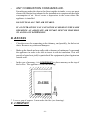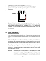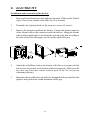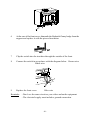
1
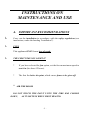
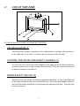
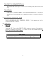
F:\Home\RD\ME\FUNNY\FUNNYGB.WP
D
IN-FIRE
Jubilee
USER’S MANUAL,
MAINTENANCE MANUAL
INSTALLATION INSTRUCTIONS
03/99
07DHIFFUA
-1-
Dear Customer!
Congratulations on the purchase of your new Bodart & Gonay appliance!
Your choice shows the interest you have for high quality products. You are
now a full member of the large international family of Bodart & Gonay customers,
who have enjoyed for many years the elegance, efficiency and reliability of our
equipment.
This is why we deem it important to provide you with this user's and
maintenance manual: to allow you to use your equipment under the best possible
conditions and in the most optimal manner, and furthermore to increase its
operating life. We strongly advise you to read it carefully.
And, of course, to store it in a place where you are sure to find it again
without any problem.
We also provide hereunder a space where you can note for yourself the date
of purchase, reference and the name and address of your supplier, so that this
information is always kept safely.
Also keep carefully the invoice or proof of purchase (necessary for the
guarantee) and we advise you to clip them together with this manual.
We wish you every satisfaction with your Bodart & Gonay equipment.
After sales service.
* Type of equipment : ..........................................
* Reference : .........................................................
* Date of purchase : ....../......./.........
* Dealer :
- Name : ...................................
- Street : ...................................
- City : ......................................
-2-
- Phone : ...................................
CONTENTS
INSTRUCTIONS ON MAINTENANCE AND USE
A. IMPORTANT RECOMMENDATIONS
4
B. CHARACTERISTICS
5
C. USE OF THE FIRE
6
D. MAINTENANCE
9
E. TROUBLE SHOOTING
11
F. GUARANTEE
12
INSTALLATION INSTRUCTIONS
A. SAFETY
14
B. RECESS
15
C. CHIMNEY
16
D. HOT AIR DUCT
17
E. ELECTRICITY
18
F. INSTALLATION OF THE FIRE
20
-3-
-4-
INSTRUCTIONS ON
MAINTENANCE AND USE
A. IMPORTANT RECOMMENDATIONS
L
Carry out the installation in accordance with the safety regulations (see
instructions, under the heading “Installation”).
L
FUEL
This appliance ONLY burns logs of wood.
L
THE FIRST TIME YOU LIGHT IT
*
If you have selected the fan option, set the fan on maximum speed to
run it in (for about 12 hours).
*
The first fire bakes the paint, which causes fumes to be given off.
" AIR THE ROOM
DO NOT TOUCH THE PAINT UNTIL THE FIRE HAS COOLED
DOWN,
AS IT SOFTENS WHEN FIRST HEATED.
-5-
B.CHARACTERISTICS
TYPE: Jubilee
RATED HEATING POWER:
47B66B4P
7 KW
FUEL:
DIAMETER OF SMOKE OUTLET:
NUMBER OF SMOKE OUTLETS / DIAMETER
WOOD CONSUMPTION (ON TOP SETTING):
VENTILATION 1 TANGENTIAL TURBINE
MAXIMUM FAN OUTPUT:
ELECTRIC POWER:
ELECTRIC VOLTAGE:
WEIGHT :
-6-
6020 Kcal
WOOD
180 MM
2 X Ø 125
2.8 Kg/h
150 M3/H
29W
230 V A.C.
77 Kg WITHOUT FAN
79 Kg WITH FAN
C.
USE OF THE FIRE
I) USE OF MOVING PARTS AND SAFETY DEVICES
AIR REGULATOR (1)
This adjusts the quantity of primary air for combustion according to the position (+
to the right and - to the left). It can be moved using the safety handle.
CLOSING THE DOOR AND SAFETY HANDLE (2)
To close the door, insert the safety handle in the top hole of the right hand door
section, and then close it until you hear the catch click. (N.B.: the catch resistance can
be adjusted using a screwdriver).
DOOR SAFETY DEVICE (3)
This device prevents the door from being opened accidentally. To use it, push the end
of the safety handle into the lower hole in the door. Pivot the safety handle to the left,
until it is horizontal, and then let it rest against the bottom of the door. Now the door
cannot be opened.
-7-
THE SWITCH (FAN OPTION) (4)
This activates the fan and gives a choice of two rotation speeds (fast and slow) and
stop.
THE FAN (5)
If this option is included, it must be switched on every time the fire is lit. The fan
should be cut off every time the door is opened and restarted as soon as you close the
door.
II) OPENING AND CLOSING THE DOOR
WHEN A FIRE IS ON, OPEN THE DOOR SLOWLY. A fast opening may lead to
a temporary spillage of smoke.
III) OPERATION
1
THE WOOD
The QUALITY of the wood is ESSENTIAL for an optimal operation of the appliance
(efficiency, cleanliness of the window, ...). A quality wood is a dry wood having dried at
least 2 years under a ventilated shelter.
Jubilee MODEL
Maximum load (only for moderate setting)
Recommended load for 1 hour on maximum setting
-8-
6 Kg
2.8 Kg
LIGHTING THE FIRE
Î
OPEN fully the air flow.
Ï
Place crumpled paper (or fire lighters) and KINDLING FIREWOOD in the
appliance on the grate.
Ð
LIGHT the FIRE.
Ñ
Leave the door SLIGHTLY AJAR to avoid an accumulation of dirt on the
window, its temperature is too low it could leads to condensation and a deposit of
particles on the glass if the door is closed to early .
Ò
As soon as the window is sufficiently HOT, CLOSE THE DOOR.
Ó
Wait until the kindling firewood burns briskly and LOAD the first logs,
choosing the smaller ones to start with.
Ô
START THE FAN (OPTION).
Õ
When the fire is burning brightly and the appliance is hot, set the air regulator
to the required position.
LONG LASTING COMBUSTION
-
Keep a bed of glowing embers of 3 to 5 cm on the bottom of the appliance.
A: Let the air inlet holes free
-9-
-
Choose logs of very high cross section.
-
Reduce the air flow according to the draught of your chimney.
REMARK:
-
-
The use at a reduced rate for a long time may, because
of condensation, lead to an accumulation of creosote in
the chimney and thus to a risk of setting the chimney on
fire.
AVOID AN OPERATING AT A REDUCED RATE WHEN THE
ATMOSPHERIC CONDITIONS ARE UNFAVOURABLE (low
pressure and high humidity) as this could cause problems .
2 FORBIDDEN FUELS
This heater is designed to burn LOGS OF WOOD ONLY.
The use of treated wood (e.g. painted) or any other recycled material giving off
gases
which are environmentally harmful or damage the components of the fire, is
FORBIDDEN and will invalidate the guarantee. As the fire has no grate, coal
must not be burned.
The use of LIQUID FUELS (e.g. petrol) is FORBIDDEN (even for lighting).
D. MAINTENANCE
CHIMNEY SWEEPING: have your chimney swept at least once a year both to comply with the LAW, and with a view to SAFETY.
-
Remove the baffle and chimney deflector (See Dismantling the baffle).
Close the door and the air regulator.
-
When the dust has fallen, just remove it with a vacuum cleaner.
Check the condition of parts subject to high combustion temperatures.
Slight deformations will not prevent them from continuing to work properly.
- 10 -
CARRY OUT THE FOLLOWING OPERATIONS:
AIR DISTRIBUTOR: If necessary, clear the air inlet holes.
FAN:
DISCONNECT from the electricity supply. Remove the frame and
take out the fan box. Dismantle the protective grid (4 screws).
Remove dust using a fine brush (not compressed air). Fit everything
back in place.
DOOR:
Check that the lock is working properly. (See installation of fire).
GLASS:
If you use a chemical product for cleaning, PROTECT exposed
painted surfaces. We recommend use of the “BG Clean”, which
you can obtain from your distributor.
PAINT:
Dirty areas can be restored using special HIGH TEMPERATURE
paint sprays which you can obtain from your supplier.
- 11 -
E. TROUBLESHOOTING
PROBLEMS
SOLUTIONS
GLASS GETTING DIRTY TOO
QUICKLY
– Check whether the fuel is damp
– Increase the fire setting
FAN
stops working
– Check that the motor is working
– Check (and reconnect) the
supply
– Check the switch
FAN
works, but weak flow
– Clean the turbine blades
– Dust the fan
DRAUGHT
too strong
– Consult your supplier
DRAUGHT
– Check the chimney (see
too weak, possibly giving off fumes
installation instructions)
into the room
– Remove any obstructions
– Have the chimney swept
Disturbances linked with
atmospheric conditions
– If this is continuous, consult your
supplier
The fire is not brisk enough
–
–
–
Check the humidity of the fuel
Check the air regulator
Clear the hole of the distributor
If there is a chimney fire, close the door and air regulator immediately.
- 12 -
F. GUARANTEE
DURATION AND LIMITATION
– 6-year guarantee on:
– 1-year guarantee on:
– no guarantee on:
the overall structure;
the internal removable parts and the fan;
the glass, bricks and cast iron plates.
RESERVATIONS
Bodart & Gonay reserve the right to modify their equipments, catalogues, and
manuals independently, at any time and without prior notice.
The validity of the guarantee is cancelled in case the mandatory recommendations
of this manual are not fulfilled.
The intervention under the guarantee are only made through the dealer on
presentation of the purchase invoice.
Parts will be delivered only against the faulty parts.
EXCLUSION
Disasters, breakdown or faulty operation linked to:
-
inadequate relation between the nominal power of the equipment and the heat
requirements of the premises;
a faulty installation or faulty connections;
an insufficient or excessive draught;
incorrect use;
non compatible fuels, destructive and/or damp fuels (treated wood,...);
consumption exceeding the use limits;
a lack of maintenance;
the use of electrical or electronic components that are not approved by
Bodart & Gonay;
any modification, transformation inside the appliance;
transport and installation.
Transport and packaging cost.
All costs not previously accepted by Bodart & Gonay.
- 13 -
Costs due to the non-use of the equipment.
TAKING EFFECT
The guarantee starts on the date written on the invoice. The invoice is the only
document valid for the guarantee.
- 14 -
INSTALLATION INSTRUCTIONS
Your dealer is the SPECIALIST that BODART & GONAY have chosen to
represent them in your area.
For your SAFETY and SATISFACTION we recommend that you entrust him
with carrying out your installation.
The appliance must be installed in compliance with the rules of building
regulations and any local regulations.
However, if you want to assume the installation, to avoid any mistakes
allow us to recommend that you:
- refer to the terms of our guarantee
- take the advice of your dealer.
As it is impossible to mention all the particularities of all cases that may occur,
we limit ourselves to the important points:
A. SAFETY:
-
-
-
COMBUSTIBLE MATERIALS must be avoided in the proximity of the
appliance and of the connection to the chimney.
Example: a decorative wooden beam above the appliance
requires to be well insulated.
It is forbidden to place the frame against combustible material (for ex : well
paper)
INSULATING MATERIALS: use preferably materials that withstand
HIGH TEMPERATURES (DO NOT USE GLASS WOOL).
Example: around a metal part linking to the chimney, a ceramic
insulation is mandatory.
THE SEALING OF THE CHIMNEY and of the linking parts is
absolutely required in order:
- to prevent any combustion gas leak
- not to interfere with the draught of the chimney
- 15 -
-
ANY COMBUSTION CONSUMES AIR.
From the gap under the door to the direct outside air intake, every one must
choose the solution best adapted to the installation to compensate the slight
consumption of air. Never create a depression in the room where the
appliance is installed.
DO NOT SEAL ALL THE AIR INTAKES.
IF AN EXTRACTION FAN CANNOT BE AVOIDED IN THE SAME
PREMISES, AN ADEQUATE AIR INTAKE MUST BE PROVIDED
TO AVOID ANY DEPRESSION.
B. RECESS
-
Clear the recess for connecting to the chimney, and possibly, for the hot air
ducts. Remove any sinks and dampers.
-
Make up the lateral and rear walls with a clearance of minimum 3 cm around
the appliance in order to be able to insert it with its insulation. This will
provide a better heat yield, in particular if the equipment is placed against an
outside wall.
-
In the case of masonry, it is FORBIDDEN to place masonry on the top of
the In-Fire. The appliance is not load bearing.
* Leave a gap of approx. 5 mm under the fire (see drawing).
C. CHIMNEY
- 16 -
The chimney flue must be made according to the best rules of the trade,
here are the most important ones:
Minimum height 4 m
-
The cross section must be neither too small (not less than the output cross
section of the equipment)
nor too large (risk of condensation and poor draught)
-
The flue must be thermally insulated
-
Avoid sloping parts, never exceed a slope of 45 ° and avoid any sharp bends
of direction (large curving radius)
-
THE OUTPUT OF THE CHIMNEY AND ITS PLACEMENT ARE
VERY IMPORTANT: ask for advice from a chimney expert (any device
which reduces the cross section at the output must be avoided)
-
If there are obstacles near the output of the chimney, they must be taken into
account.
-
Foresee later chimney sweepings
-
Connect only one appliance per flue
-
In case of a double flue:
* choose the best one
* seal the one that is not used
-
In case of a lateral connection to an existing flue, make one of the following
assemblies:
- 17 -
-
TIGHTNESS AND CLEANLINESS are important.
Seal all the linking parts so that the bottom of the flue socket is
placed 10 mm higher than the top of the appliance that will be
introduced.
.
-
On installation, if necessary install a draught regulator.
The depression must be measured at the time of the first fire. The
IDEAL DRAUGHT is between 12 and 20 Pa (1.2 to 2 mm water
column). If it goes outside these limits, it is MANDATORY to act on
the chimney.
D. HOT AIR DUCT
Two ducts can be connected to the top of the appliance to heat adjacent
rooms. (Their installation is recommended if the fire is installed without the
fan).
When installing these ducts, limit their length, never bring them back down,
avoid bends and changes of direction as much as possible, as the losses of
speed caused reduce the efficiency of the hot air outlets at the end of the run.
Depending on requirements and the risks of heat loss, it may be of use to
insulate these ducts. Take care, as without a fan, the hot air temperature may
reach 200oC. It is therefore vital to isolate the ducts and their outlets from
any combustible material.
Remark:
an efficient hot air circuit requires an air return so as to avoid
depression in the room where the appliance is. For each room
concerned, a ventilating grid placed near the ground allows the
cooled air to come out of the place in order to complete its circuit.
- 18 -
E. ELECTRICITY
Installation and connection of the fan box
1
Remove the front frame by simply pulling it forwards. (Take out the 4 lateral
clips). Then let the central screw slide out of its location.
2
Dismantle the right hand side of the protective screen (2 screws).
3
Remove the protective grid from the fan box. Connect the female connector
of the silicone cable to the connector inside the fan box. Bring the silicone
cable out through the right or left hand side opening in the box according to
the side selected for the supply, and locate the rigid cable grip.
4
Attach the self-adhesive tabs to the bottom of the fire so as to place the fan
box as close as possible to the bottom of the heating body. Make sure the
box does not come into contact with the parts of the fire (to prevent
vibration problems).
5
Bring the silicone cable back out of the fire through the hole provided for this
purpose and position the round membrane cable grip.
- 19 -
5°
6
At the rear of the front cover, dismantle the Bodart & Gonay badge from the
support and replace it with the pierced insulation.
7°
6°
6°
7
Clip the switch into the insulator through the outside of the front.
8
Connect the switch in accordance with the diagram below. Brown wire
Black wire
9
Replace the front cover.
Blue wire
Reminder: - Don’t use the same circuit as your video and audio equipment.
- The electrical supply must include a ground connection.
- 20 -
F. INSTALLING THE FIRE
1
Dismantle removable parts:
the door (open beyond 45o and lift)
the baffle and chimney deflector
the false brick set.
2
Insert the fire in the recess and locate in correct position.
3
Connect the hot air fittings if any, through the chimney outlet.
Reminder: If the fire is installed without a fan, installation of the hot air
fittings is recommended to improve the natural convection.
4
From inside the fire, find the fitting and pull it until it sticks. Then fold back
the safety lugs.
5
Make the electric connection through one of the sides, either right or left (fan
option).
6
Fit the outer frame, placing the screw in line with the housing.
7
Fit the removable parts.
8
Check that the moving parts and the fan are working (LEAVE ON
MAXIMUM SPEED FOR THE FIRST FIRE).
*
Check that the door is working correctly (if necessary, adjust the
catch tightness using the 2 screws).
- 21 -
*
With the door closed, check that there is no clearance between the
door and the heating body, by pressing on the right hand side of the
door. A slight clearance can be accepted at the lower right hand
corner.
9
Dust visible painted surfaces.
10
Light the first fire to bake the paint (air the room and do not touch the fire).
CHECK THE DRAUGHT.
- 22 -
SPARE PARTS LIST
Ref.
Code No.
DESCRIPTION
1
37B66008
Chimney deflector
2
37B66007
Baffle
3
37B66006
Distributor
4
37B66005
Air regulator
5
37B66013
False brick 240 x 120 x 30
6
37B66021
False brick 240 x 100 x 30
7
37B66019
False brick 150 x 93 x 30
8
37B66018
Air duct
9
07CB300
Brick 240 x 120 x 30
10
07CB313
Brick 240 x 60 x 30
11
07RV1037
Glass
12
07ADVSH1 Catch
13
37B66003
Fitted door
14
37B66004
Outer frame
15
37B66009
Catch support
16
37116411
Chimney connection fitting Ø 180
17
07PB0104
Safety handle
18
37115018
Poker
19
07I79902
Door washer
20
07I79903
Air regulator washer
- 23 -
- 24 -