1
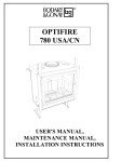
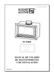
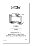
OPTIFIRE
703-704
783-784
USER’S MANUAL,
MAINTENANCE MANUAL,
INSTALLATION INSTRUCTIONS
02/2001
Dear Customer!
Congratulations on the purchase of your new Bodart & Gonay appliance!
Your choice shows the interest you have for high quality products. You are now a full member of the large
international family of Bodart & Gonay customers, who have enjoyed for many years the elegance, efficiency
and reliability of our equipment.
This is why we deem it important to provide you with this user's and maintenance manual: to allow you to use
your equipment under the best possible conditions and in the most optimal manner, and furthermore to
increase its operating life. We strongly advise you to read it carefully.
And, of course, to store it in a place where you are sure to find it again without any problem.
We also provide hereunder a space where you can note for yourself the date of purchase, reference and the
name and address of your supplier, so that this information is always kept safely.
Also keep carefully the invoice or proof of purchase (necessary for the guarantee) and we advise you to clip
them together with this manual.
We wish you every satisfaction with your Bodart & Gonay equipment.
After sales service.
* Type of equipment: ....................................................................................................
* Reference: ....................................................................................................................
* Date of purchase: ....../....../20......
* Dealer: - name: ...........................................................................................................
- street: ..........................................................................................................
- city: ...............................................................................................................
- phone: .............................................................................................................
In order to put back the baffles in the position adapted to your chimney stack after a chimney
sweeping, note here the ideal position (cf. page, adjustment of the baffles):
Upper baffle: open - ½ open - closed
Lower baffle: open - closed
3
TABLE OF CONTENTS
USERS AND MAINTENANCE MANUAL . . . . . . . . . . . . . . . . . . . . . . . . . . . . . 4
A
IMPORTANT RECOMMENDATIONS . . . . . . . . . . . . . . . . . . . . . . 4
B
OPERATION OF THE APPLIANCE . . . . . . . . . . . . . . . . . . . . . . . . 5
C
MAINTENANCE . . . . . . . . . . . . . . . . . . . . . . . . . . . . . . . . . . . . . . . 9
D
OPERATION ANOMALIES . . . . . . . . . . . . . . . . . . . . . . . . . . . . . . 10
E
GUARANTEE . . . . . . . . . . . . . . . . . . . . . . . . . . . . . . . . . . . . . . . . . 11
INSTALLATION INSTRUCTIONS . . . . . . . . . . . . . . . . . . . . . . . . . . . . . . . . . 13
A
SAFETY . . . . . . . . . . . . . . . . . . . . . . . . . . . . . . . . . . . . . . . . . . . . . 13
B
RECESS . . . . . . . . . . . . . . . . . . . . . . . . . . . . . . . . . . . . . . . . . . . . . 13
C
CHIMNEY . . . . . . . . . . . . . . . . . . . . . . . . . . . . . . . . . . . . . . . . . . . 13
D
SUPPLY OF COMBUSTION AIR . . . . . . . . . . . . . . . . . . . . . . . . . 15
E
CONVECTION SYSTEM . . . . . . . . . . . . . . . . . . . . . . . . . . . . . . . . 15
F
ELECTRICAL CONNECTION . . . . . . . . . . . . . . . . . . . . . . . . . . . . 15
G
ADJUSTMENT OF THE BAFFLES . . . . . . . . . . . . . . . . . . . . . . . . 16
H
DISMANTLING THE BAFFLES . . . . . . . . . . . . . . . . . . . . . . . . . . 17
I
INSTALLATION OF THE APPLIANCE . . . . . . . . . . . . . . . . . . . . 18
J
FAN INSTALLATION . . . . . . . . . . . . . . . . . . . . . . . . . . . . . . . . . 22
K
HOW TO INSTALL A THERMOCONTACT . . . . . . . . . . . . . . . .
4
24
USERS AND MAINTENANCE MANUAL
A
IMPORTANT RECOMMENDATIONS
S Carry out the installation and follow the safety rules (cf. Installation instructions).
FIRST FIRE
C Set the fan to maximum speed to run it in (during about 12 hours).
C The first fire bakes the paint which leads to an emission of smoke.
(L VENTILATE THE ROOM)
DO NOT TOUCH THE PAINT UNTIL THE APPLIANCE HAS COOLED,
BECAUSE IT GETS SOFT AT THE FIRST FIRING.
S IT IS MANDATORY AT EACH FIRE:
* TO SHUT THE DOOR OF THE ASH BOX
* TO CLOSE THE DOOR FLAP
* OPERATE THE CONVECTION FAN (except when running at the minimum rate)
S IMPORTANT REMARK:
To have a good airtightness adjust the ventilation cap with the front ashtray box.
5
B
OPERATION OF THE APPLIANCE
I.
USE OF THE CONTROL AND SAFETY DEVICES
1) The door flap: NEVER KEEP IT OPEN DURING THE OPERATION OF THE
APPLIANCE.
2) The thermostat: It adjusts the quantity of primary air for burning in function of its
position. Its flap opens and closes according to the temperature
of the convection chamber. Its control button is telescopic to
make its operation easier.
3) The ashpan door: It provides access to the ash box and to the de-ashing arm. IT
MUST ALWAYS BE TIGHTLY CLOSED WHEN THE FIRE IS
ON (otherwise the combustion air is not controlled and the fire
races => OVERHEATING OF THE APPLIANCE).
4) De-ashing arm: To use it, pull it towards the front. It is used to adapt the grate to
the type of fuel to be burnt (left position: open grate for coal;
right position: closed grate for wood). Removing the ashes is
made by moving it from the right to the left.
5) The ash pan: In the shape of a shovel to allow the collection of ashes at the back
of the equipment. Monitor the filling of the ash pan and empty it
before it overflows.
6) Closing the door and the "cold handle": Place the cold handle in the hole of the
latch to open and close.
6
7) Microswitch: If ventilation installed, a switch which automatically stops the fan
convection when the door is opened.
8) Adjuster: 1 Speed regulation
2 Fuse (remove the button, unscrew the plate, pull to replace; replace with an
identical fuse).
3 Regulation screw of the minimal speed under the button (calibrated in the
factory).
II.
OPENING AND CLOSING THE DOOR
WHEN A FIRE IS ON, OPEN THE DOOR SLOWLY. A fast opening
may lead to a temporary spillage of smoke.
TO SHUT THE DOOR, lift the handle, press the door against the
combustion chamber in order to crush the seal slightly, then lower the
handle to its stop position.
III.
OPERATING WITH DIFFERENT FUELS
1
Wood
The quality of the wood is ESSENTIAL for an optimal operation
of the appliance (efficiency, cleanliness of the window, ...). A
quality wood is a dry wood having dried at least 2 years under a
ventilated shelter. To use your appliance with WOOD, you must
place the GRATE in the CLOSED POSITION.
Closed position
7
Model
OPTI 700
OPTI 780
Maximum load (for low rate burning only)
9 Kg
11 kg
Recommended load for 1 hour at max.rate
3,5 Kg
4,5 Kg
Remark: The use of briquettes is similar to operation with wood.
LIGHTING THE FIRE
1.
OPEN fully the air flow: THERMOSTAT on 9. Place the grate in the open
position (lever to the left).
2.
Place crumpled parer (or fire lighters) and KINDLING FIREWOOD in the
appliance on the grate.
3.
LIGHT THE FIRE.
4.
If the door is closed too early, too low temperature can lead to
condensation and a deposit of particles on the glass.
5.
As soon as the window is sufficiently HOT, CLOSE THE DOOR.
6.
Wait until the kindling firewood burns briskly and LOAD the first logs,
choosing the smaller ones to start with.
7.
START the VENTILATION (if installed).
8.
When the fire is brisk and the unit is hot, CLOSE THE GRATE (lever to
the right), adjust the thermostat to the position wanted.
9.
When burning a fame, ADJUST THE SPEED OF THE VENTILATION in
function of the quantity of hot air that you need.
LONG DURATION COMBUSTION
- Keep a bed of glowing embers of 3 to 5 cm on the bottom of the appliance.
- Choose logs of very high cross section
- Position the thermostat in accordance with the draught of your chimney. A
reduced rate is generally obtained from 0 to 3.
Remark: The use at a reduced rate for a long time may, because of
condensation, lead to an accumulation of creosote in the chimney on
fire.
8
AVOID OPERATING AT A REDUCED RATE WHEN THE
ATMOSPHERE CONDITIONS ARE UNFAVOURABLE (low
pressure and high humidity) as this could cause problems.
2 Coal
Use anthracite or non bituminous coal, with a size of 20/30 (or 12/22 if the
draught is sufficient). To use your appliance with COAL, place the GRATE in
the OPEN POSITION.
Open position
LIGHTING A COAL FIRE
Points 1 to 5 as for wood fuel.
6.
START the VENTILATION.
7.
Place two coal shovels full of coal, WITHOUT SPREADING IT on the top of
the briskly burning fire.
8.
As soon as the fire burns through, place a LOAD of about 6 kg.
9.
When the fire has burn through the mass (flames will appear), add a SECOND
LOAD.
10. Let the fire increase before reducing GRADUALLY the air admission until
the position corresponding to the heat requirement is reached.
11. ALSO ADJUST THE SPEED OF THE VENTILATION (option).
Remark: Do not use the equipment with coal in warm weather. The draught and
the burn rate being reduced, the combustion risks becoming incomplete.
3 Prohibited fuels
9
The use of treated wood (painted, ... etc.) and any other salvaged material that can
emit noxious gazes for the environment and aggressive towards the components of
the appliance is NOT ALLOWED and eliminates the rights of guarantee. For the
same reasons, PETROLEUM COKE must not be used. The use of LIQUID FUELS
(petrol, ...)is FORBIDDEN (even to light the fire).
IV. OPERATION OF THE THERMOCONTACT (option)
This thermocontact is a switch that automatically switches the ventilation on when the
equipment is hot and stops it when it has cooled. At the time of LIGHTING, there is
a DELAY of about 20 minutes before it switches on, this is NORMAL.
C
MAINTENANCE
CHIMNEY SWEEPING: Not only to comply with the LAW, but from the point of view of
SAFETY, have the chimney swept at least once per year.
- Dismantle the 2 baffles (cf. “Dismantling the baffles”). Close the door, thermostat and
the ash box door.
- Place the grate in the closed position (wood).
- After dust has settled, it can be removed with a vacuum cleaner.
General Maintenance
Components exposed to high combustion temperatures should be controlled regularly.
Small deformation does not alter a normal operating.
CARRY OUT THE FOLLOWING OPERATIONS
- AIR DISTRIBUTOR: Clear, if necessary, the air intake holes.
- GRATES: Check that there are no objects limiting their movements.
- FAN: DISCONNECT the power supply, DISMANTLE the fan and REMOVE it.
CLEAN the vanes of the turbine using a brush (COMPRESSED AIR IS NOT
ALLOWED)
Reassemble all.
- THERMOSTAT: Check its correct clearance. Your dealer can check the adjustment.
- DOOR: Check the sealing of the stainless steel seal.
If necessary, your dealer may adjust or replace it. Check the correct operation
of the lock and of the opening safety.
10
- WINDOW:
If, for cleaning, you use a chemical product, PROTECT the exposed
painted surfaces. We recommend the use of the “BG Clean” product
available at your dealer’s.
- ASH BOX DOOR: Check the seal and if necessary replace it to ensure correct
sealing. Check the operation of the spring clip.
- REFRACTORY BRICKS: A split brick may function quite correctly. However, a
missing piece should lead to the replacement to maintain an
efficient protection of the appliance.
- PAINT: The soiled areas may be restored using aerosols of a special HIGH
TEMPERATURE paint, available at your dealer’s.
- LUBRIFICATION: In frequent use, it is recommended to lubricate every year the
following elements:
- door and door flap: hinges and lock;
- thermostat: control axis.
DO NOT USE NORMAL GREASE. In fact, subjected to high temperatures it would dry up
and lead to a seizing. If necessary, clean thoroughly the surfaces, then apply a GREASE
RESISTANT TO HIGH TEMPERATURES, available at your dealer’s.
D
OPERATION ANOMALIES
CURES
ANOMALIES
THE WINDOW GETS DIRTY TOO QUICKLY
- Check the humidity of the fue;l
- Open the passage of the baffles
( cf. "Adjusting the baffles");
VENTILATION
Does not function
- Check the operation of the motor;
- Check the microswitch;
- Check (and replace) the fuse of the variator;
- Check the thermocontact;
- Check (and repair) the power supply.
VENTILATION
Operates but the flow is low
- Clean the vanes of the turbines.
Excessive DRAUGHT
- Tighten the passage of the baffles
(cf. Installation);
- Consult your dealer.
DRAUGHT
Too low with a possible generation of smoke in the room
- Check the chimney (cf. installation instructions);
- Remove the possible obstruction;
- Have the chimney swept;
- Open the passage of the baffles
(cf. "Adjustment of the baffles");
11
Trouble linked to weather conditions
- If this is permanent, consult your dealer.
THE FIRE IS NOT BRISK ENOUGH
- Check the humidity of the fuel;
- Check the thermostat;
- Empty the ash box;
- Clear the holes of the distributor.
THE THERMOSTAT DOES NOT CLOSE ANYMORE:
- A foreign body prevents the closing of the flap
- Mechanical blocking
- Remove the foreign body.
THE THERMOSTAT REMAINS CLOSED:
1 When COLD, the flap only rises from mean positions
2 When COLD, the flap does not rise
- Calibrate the adjustment.
- Replace the thermostat.
THE FIRE CANNOT BE CONTROLLED:
- The DOOR of the ash box is open or unsealed
- The DOOR of the appliance is not sealed
- Replace the thermostat.
- Check the correct closing of the ash box door;
- Check the seal, replace if necessary;
- Adjust again the door seal;
- Adjust again the position of the closing roller.
In case of chimney catches fire, immediately close the door, the ash box door, close the
thermostat and the air doser.
E
GUARANTEE
DURATION AND LIMITATION
-
6 years guarantee on: the general structure
2 years guarantee on: the inner removable parts
1 year guarantee on: grates, thermostat, fan and speed variator
no guarantee on: window, seals, bricks and cast iron plates
RESERVATIONS
Bodart & Gonay reserve the right to modify their equipments, catalogues and manuals
independently, at any time and without prior notice.
The validity of the guarantee is cancelled in case the mandatory recommendations of this
manual are not fulfilled.
The interventions under the guarantee are only made through the dealer on presentation of
the purchase invoice.
Parts will be delivered only against the faulty parts.
12
EXCLUSION
Disasters, breakdown or faulty operation linked to:
S inadequate relation between the nominal power of the equipment and the heat
requirements of the premises;
S a faulty installation or faulty connections;
S a damage to the thermostat through overheating due to intensive use:
* the ash box door is left open
* the ventilation is left off
S an insufficient or excessive draught;
S incorrect use;
S non compatible fuels, destructive and/or damp fuels (treated wood, ...);
S consumption exceeding the use limits;
S a lack of maintenance;
S the use of electrical or electronic components that are not approved by
Bodart & Gonay;
S any modification, transformation inside the appliance;
S transport and installation.
S Transport and packaging cost.
All costs not previously accepted by Bodart & Gonay.
Costs due to the non-use of the equipment.
TAKING EFFECT
The guarantee starts on the date written on the invoice. The invoice is the only document
valid for the guarantee.
Your dealer is the SPECIALIST that BODART & GONAY has chosen to represent they
your area.
For your SAFETY and SATISFACTION we recommend that you entrust him with carrying
out your installation.
The appliance must be installed in compliance with the rules of building regulations
and any local regulations. As there are no precise regulations in Belgium, the
French installation regulations (D. T. U. 24.2.2) are applicable.
However, if you want to assume the installation, to avoid any mistakes allow us to
recommend that you:
- refer to the terms of our guarantee;
- take the advice of your dealer.
As this is impossible to mention all the particularities of all cases that may occur, we limit
ourselves to the important points:
13
INSTALLATION INSTRUCTIONS
A
SAFETY
- COMBUSTIBLE MATERIALS must be avoided in the proximity of the appliance and
of the connection to the chimney.
Example: a decorative wooden beam above the appliance requires to be well insulated.
- INSULATING MATERIALS: use preferably materials that withstand HIGH
TEMPERATURES (DO NOT USE GLASS WOOL).
Example: around a metal part linking to the chimney, a ceramic insulation is
mandatory.
- THE SEALING OF THE CHIMNEY and of the linking parts is absolutely required in
order:
- to prevent any combustion gas leak;
- not to interfere with the draught of the chimney.
- Any COMBUSTION consumes AIR.
From the gap under the door to the direct outside air intake, everyone must choose the
solution best adapted to the installation to compensate the slight consumption of air.
Never create a depression in the room where the appliance is installed.
DO NOT SEAL ALL THE AIR INTAKES.
IF AN EXTRACTION FAN CANNOT BE AVOIDED IN THE SAME PREMISES, AN
ADEQUATE AIR INTAKE MUST BE PROVIDED TO AVOID ANY DEPRESSION.
B
RECESS
- Clear the recess for connecting to the chimney, and possibly, for the hot air ducts.
Remove any sinks and dampers.
- Make up the lateral and rear walls with a clearance of 2 cm around the appliance in order
to be able to insert it with its insulation. This will provide a better heat yield in
particular if the equipment is placed against an outside wall.
- In the case of masonry, it is FORBIDDEN to place masonry on the top of the Optifire.
The appliance is not load bearing.
C
CHIMNEY
The chimney flue must be made according to the best rules of the trade, here are the
most important ones:
- minimum height 4 m;
- the cross section must be neither too small (not less than the output cross section of
the equipment, nor too large (risk of a condensation and poor draught);
- the flue must be thermally insulated;
- avoid sloping parts, never exceed a slope of 45° and avoid any sharp bends of direction
(large curving radius);
- THE OUTPUT OF THE CHIMNEY AND ITS PLACEMENT ARE VERY IMPORTANT:
14
-
-
ask for advice from a chimney expert (any device which reduces the cross section at the
output must be avoided);
if there are obstacles near the output of the chimney they must be taken into account;
foresee later chimney sweepings;
connect only one appliance per flue;
in case of a double flue:
* choose the best one;
* seal the one that is not used.
in case of a lateral connection to an existing flue, make one of the following
assemblies:
SOOT TRAP
- TIGHTNESS AND CLEANLINESS are important
- Seal all the linking parts so that the bottom of the flue socket is placed 10 mm higher
than the top of the appliance that will be introduced.
Tightness
Infire height + 10 mm
- On installation, if necessary, install a draught regulator.
The depression must be measured at the time of the first fire. THE IDEAL
DRAUGHT is between 10 and 20 Pa (1 to 2 mm water column). If it goes outside
these limits, it is MANDATORY to act on the chimney.
15
D
SUPPLY OF COMBUSTION AIR
EVERY COMBUSTION CONSUMES AIR.
A supplementary air supply is necessary if the room is too airtight. In all the cases, avoid
causing a depression in the room. If there is a cooker in the room that is absolutely
necessary, foresee a sufficient air entry to avoid any depression.
E
CONVECTION SYSTEM
1 NATURAL CONVECTION
You must open the 4 central inlets of the hot air outflow.
For the entry of convection air, the opening under the fan has to be open what the height
of foot regulation is.
Provide a way of ± 7 dm² (without filter) in the masonry as air entry.
2 FORCED CONVECTION (FAN OPTION)
It is advised to open the 4 inlets of hot air outflow.
Provide a way of minimum 6 dm² without filter or minimum 9 dm² with dust filter in the
masonry for the entry of convection air.
It is necessary to separate the air arrival and outflow correctly in the masonry.
3 HOT AIR DUCTS
Thermally insulated ducts are necessary for the optimal operation of the appliance
(these cause a “draught” for the convection air). Using A MAXIMUM DUCTS
IMPROVES THE YIELD AND THE NOISE (sent out through the air moving).
Limit the length and the direction modifications when installing these ducts, bend
the most large and avoid using OUTFLOW GRILLS with a low way coefficient
because the caused losses of speed decrease the efficiency of the hot air outflows.
Remark: Do not push air in another room without providing a hole of air return.
F
ELECTRICAL CONNECTION
- Avoid using the same circuit as those of the audio and video equipment.
- Do not install the variator near these household equipments
BEWARE! The use of a variator and/or an unsuitable fuse that is not approved by Bodart &
Gonay risks the exclusion to the right of the guarantee on the whole of the electric
16
equipment.
The electric connection has to be done on a 230-vac 50 Hz line protected by fuses with an
earth plug.
G
ADJUSTMENT OF THE BAFFLES
The baffle system is designed to adapt the appliance to the draught of the chimney. The
baffles rest on square supports.
Baffles from the most closed to the most opened position (pictures 1 to 3).
Picture 4: wrong position
The upper baffle has on each side 3 positioning notches, allowing to open or to close the
flow of smoke at the back, as well as release notch for the assembly and dismantling of the
baffles.
1
2
1 POSITIONING NOTCHES
2 RELEASE NOTCH
17
The lower baffle may be turned around and thus open the passage for the smoke in the front
(for instance if the equipment forces back too easily). It also includes two release notches.
1 POSITIONING NOTCH
2 RELEASE NOTCH
The most closed position is the best for the efficiency of the appliance. However, if the
equipment tends to smoke back, open the baffles gradually.
H
DISMANTLING THE BAFFLES
1 Place the upper baffle in the release position
2 Raise slightly the lower baffle and move it to bring the release notch at the height of the
square support.
3 Lift one side and try to lower the other side of the baffle by passing the square support
through the notch.
4 Remove the baffle obliquely outside of the appliance.
5 Raise slightly the upper baffle and move it to bring the release notch at the height of the
square support.
6 Lower one side of the baffle by passing the square support through the notch.
7 Remove the baffle obliquely outside of the appliance.
To reassemble them, proceed inversely with the same steps.
I
INSTALLATION OF THE APPLIANCE
18
- Unblock the used holes of the convection circuit.
- Determine the height (telescopic feet). BEWARE! Respect the minimal sucking up
section of the convection air.
- Provide a sufficient place for the fan, if necessary.
- Insulate thermally the back wall.
- Install the appliance in height and LEVEL (right-left and before and behind).
- You must pin the feet. Therefore: bore a 5,25 diameter with the delivered bit and place
the 6 auto tapping screws.
- Provide a passage of the electrical feeding wire of the motor when making the masonry.
- Connect the hot air tubes through the chimney outlet, if necessary.
- Take the tube out through the inside of the fireplace and push it until jamming. Then
shut down the security flaps.
19
- Insulate completely the appliance and also the hot air ducts.
- Fit the brickwork: first the back and then the sides.
BRICK REFERENCE
DIMENSIONS (mm)
1
07CB315
300 x 150 x 30
2
07CB344
300 x 90 x 30
3
07CB300
240 x 120 x 30
CAST IRON REFERENCE
DIMENSIONS
1
07FF0305
300 x 150 x 30
2
07FF0306
300 x 90 x 30
3
07FF0301
240 x 120 x 30
-
Check the position of the baffles.
-
We advise to make an operation test before bricking up around the appliance.
-
Realize the frame of the appliance. (In the conception of the frame, do not forget to
provide the MINIMAL SECTION for the passage of the CONVECTION CIRCUIT - see
chap. E. Convection circuit).
-
Fitting the frame.
Fit the frame (pictures 2-3). Just slide it between the frame and the springs.
-
Reassemble the movable parts. Place the baffles in the most closed position (see chap.
G Adjustment of the baffles).
-
Remove the dust on the visible painted surfaces.
-
Make a first fire to bake the paint (ventilate the room and do not touch the appliance).
CHECK THE DRAUGHT.
20
-
Adjust the position of the baffles, if necessary (cf. Adjustment of the baffles).
Note the ideal position of the baffles for your chimney in the space provided on
the first page of this manual. This will allow you to position them again
correctly after a chimney sweeping.
21
22
17
8
4
15
24
5
20
21
13
7
23
28
16
1
6
3
2
18
12
9
14
11
19
10
27
26
25
22
J
FAN INSTALLATION
To install the fans, we advise you to take off the frame and the door.
The fan is to install through the inside. Take off the 2 fire grates and their stainless steel
blocking parts in front of them, the bricks behind and on the sides and the grates support.
Unscrew the 6 screws from the ash-pan’s box.
Take off the ash-pan and then the box through the ash-pan door.
23
You can make the electrical connexion. The fan wire need to pass through the dedictated
hole on the left side of ash box (foto 4). Then you can place the switch support on the
appliance and screw it (foto 5).
Foto 4
Foto 5
Connect with the fan. Introduce it in the insert (be careful with the way !).
Check the cable carefully and connect the variator on the left side from the insert.
Now you can rebuilt the insert.
24
K
HOW TO INSTALL A THERMOCONTACT
1. Screw the thermocontact on the back side from the electrical box. (B) (1 nut is fixed). Be carefull
Don’t screw the thermocontact too hord.
2. Disconnect a terminal spade tag from one of the doorswitch terminals (A) and connect it to one of
the thermocontact terminals (A). Connect the remaining cable to the two free terminals.
25