1
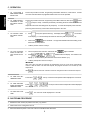
TCO2114
P/N 43336
Rev. B V1 5/00
Domestic, Std. Export
& European Export
Models:
TCO21140063 (USA & std. export, 208V)
TCO21140066 (USA & std. export, 240V)
TCO21140035 (European export, 230V)
TCO21140077 (European export, 380-400V)
Conveyor Oven
Combinations:
Single Oven
Double Oven (Two-Stack)
Triple Oven (Three-Stack)
OWNER'S OPERATING
& INSTALLATION
MANUAL
© 2000 CTX, A Middleby Company
is a registered trademark of Middleby Marshall, Inc. All rights reserved.
Middleby Cooking Systems Group 1400 Toastmaster Drive Elgin, IL 60120 (847)741-3300 FAX (847)741-4406
página 37
TM
ESPAÑOL
page 25
FRANÇAIS
seite 13
DEUTSCH
page 1
ENGLISH
ENGLISH/German
French/Spanish
TABLE OF CONTENTS
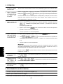
WARNING: IN CASE OF FIRE
Disconnect the oven from its power source
IMMEDIATELY. Shutting down the electrical
heating elements allows the unit to cool, making it
easier to put out the fire.
SECTION 1
DESCRIPTION .............................................. 3
ENGLISH
WARNING: FOR YOUR SAFETY
DO NOT STORE OR USE GASOLINE OR OTHER
FLAMMABLE VAPORS OR LIQUIDS IN THE
VICINITY OF THIS OR ANY OTHER APPLIANCE
A. Features .......................................................... 3
WARNING
IMPROPER INSTALLATION, ADJUSTMENT,
ALTERATION, SERVICE OR MAINTENANCE
CAN CAUSE PROPERTY DAMAGE, INJURY OR
DEATH. READ THE INSTALLATION AND
OPERATING INSTRUCTIONS THOROUGHLY
BEFORE INSTALLING OR SERVICING THIS
EQUIPMENT.
SECTION 2
INSTALLATION ............................................ 4
B. Component Location and Function .................. 3
C. Electrical Specifications .................................. 3
A. Installation Options and Kit Availability ........... 4
B. Assembly ......................................................... 4
C. Electrical Connection ...................................... 4
SECTION 3
OPERATION ................................................. 5
WARNING
DISCONNECT THE OVEN FROM ITS
ELECTRICAL POWER SUPPLY BEFORE
CLEANING OR SERVICING.
A. Location and Function of Controls ................... 5
B. Daily Startup Procedure .................................. 5
CAUTION
Using any parts other than genuine CTX factory
parts relieves the manufacturer of all liability.
C. Operation ......................................................... 6
D. Shutdown Procedure ....................................... 6
IMPORTANT
Contact your authorized service agent to perform
maintenance and repairs. A service agency
directory is supplied with your oven.
E. Programming Preset Menu Selections ............ 7
IMPORTANT
CTX (manufacturer) reserves the right to change
specifications and product design without notice.
Such revisions do not entitle the buyer to
corresponding changes, improvements, additions or
replacements for previously purchased equipment.
H. Daily Cleaning ................................................. 9
F. Cooking Time and Temperature Guidelines .... 8
G. Draft Curtain Adjustment ................................. 8
I.
Display Messages and Error Codes .............. 10
SECTION 4
ELECTRICAL WIRING DIAGRAMS ............ 11
A. Wiring Diagram and Schematic:
TCO21140063 (USA & Std. Export, 208V)
and TCO21140066 (USA & Std. Export,
240V) ............................................................. 11
RETAIN THIS MANUAL FOR FUTURE
REFERENCE
This manual provides detailed information for the
installation and operation of your conveyor oven. It
also contains information to assist the operator in
diagnosing problems in the event of a malfunction.
This manual is an important tool for the operator
and should be kept readily available.
B. Wiring Diagram and Schematic:
TCO21140035 (European Export, 230V) ...... 11
C. Wiring Diagram and Schematic:
TCO21140077 (European Export,
380-400V) ...................................................... 12
© 2000 CTX, A Middleby Company
is a registered trademark of CTX, A Middleby Company. All rights reserved.
CTX
1400 Toastmaster Drive
Elgin, IL 60120
USA
(847)741-3300
Middleby Corp 24-Hour Service Hotline 1-800-238-8444
www.middleby.com
2
FAX (847)741-4406
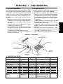
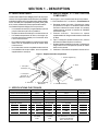
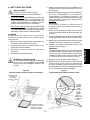
A. FEATURES
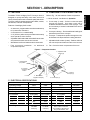
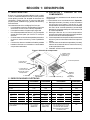
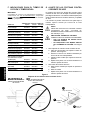
B. COMPONENT LOCATION AND FUNCTION
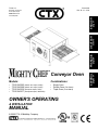
The Model TCO2114 Mighty Chef Conveyor Oven is
designed to quickly and easily cook, bake, and broil a
variety of food products with consistent quality and results.
The oven is ideal for preparing pizza, garlic toast, cookies,
sandwiches, and other food products.
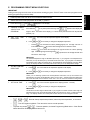
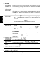
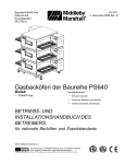
Refer to Fig. 1 for the locations of these components.
1-3.Oven controls - see Section 3, Operation.
4. Crumb trays (3 total) - Collect crumbs that pass
through the conveyor. One center crumb tray is
located underneath the center of the conveyor. One
end crumb tray is located underneath EACH end of
the conveyor.
Features of the Mighty Chef include:
An electronic, programmable controller that allows up
to 5 preset menu selections
A cool exterior for increased safety
A 14 (356mm)-wide conveyor belt that can be easily
set to operate in either direction
Adjustable draft curtains that reduce draft into the oven
and prevent heat loss into the environment
Welded and reinforced stainless steel construction
Fast countertop installation - no additional
components required
5. Conveyor end trays - Provide additional loading/exit
space at the ends of the conveyor.
6. Conveyor - Transports the product through the oven,
and between the top and bottom heating elements.
7. Adjustable draft curtains (2 total) - Reduce draft into
the oven and prevent heat loss into the environment.
8. Fan - Cools the interior components of the oven.
Figure 1 - Component location
7. Adjustable draft
curtains (2)
6. Conveyor
1. Power On/Off
(I/O) switch
2. Conveyor
reversing
switch
8. Fan
5. Conveyor
end trays (2)
3. MenuSelect®
keypad and display
4. Crumb trays (3)
C. ELECTRICAL SPECIFICATIONS
Operating Voltage
Frequency
Phase
kW Rating
Current Draw
TCO21140063
TCO21140066
TCO21140035
TCO21140077
208V
240V
230V
380-400V
50/60 Hz
50/60 Hz
50 Hz
50 Hz
1 Ph
1 Ph
1 Ph
3 Ph
5.0kW
5.3kW
5.0kW
5.0kW
24.0A (total)
22.1A (total)
21.1A (total)
L1
N/A
N/A
N/A
0.3A
L2
N/A
N/A
N/A
10.5A
L3
N/A
N/A
N/A
10.3A
N
Cord/Plug Information
N/A
N/A
N/A
10.3A
Attached cord
with NEMA
6-30P plug
Attached cord
with NEMA
6-30P plug
Kabelmetal-type HO7RN-F cord
with 3 x 4.0mm conductors
and moulded-on IEC 309 plug
Plug is rated 230VAC, 32A
N/A
3
ENGLISH
SECTION 1 - DESCRIPTION
SECTION 2 - INSTALLATION
ENGLISH
IMPORTANT
IT IS THE CUSTOMERS RESPONSIBILITY TO REPORT ANY
CONCEALED OR NON-CONCEALED DAMAGE TO THE
FREIGHT COMPANY.
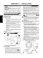
A. INSTALLATION OPTIONS & KIT AVAILABILITY
If the installation will require two or three ovens to be stacked,
you must use the separately-available Stacking Kit (P/N
T2114STACK). One Kit is required for a two-stack, while two
kits are required for a three-stack. Stacking more than three
ovens is not permitted.
1.
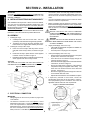
B. ASSEMBLY
Installing the Legs
a. Carefully tilt the oven onto its rear side. The front
(controller) side should be facing directly upwards.
b. Thread the four legs into the holes provided on the
bottom of the oven. Tighten them until they are secure.
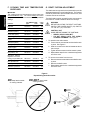
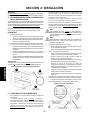
2.
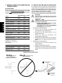
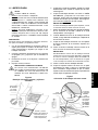
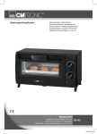
Installing the Conveyor End Trays
a. Press one of the conveyor end trays down over the
end plate of the conveyor frame, as shown in Figure
2.
b. Fasten the end tray in place with one of the supplied
8-32x3/8 screws, as shown in Figure 2.
c. Repeat the above steps to install the second end tray
at the opposite end of the conveyor frame.
WARNING
ENSURE THAT ANY PACKING MATERIAL RESIDUE
HAS BEEN REMOVED FROM INSIDE THE OVENS
COOKING CHAMBER.
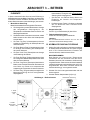
2.
Single-phase Mighty Chef ovens only:
Check that the appropriate receptacle is available for
the power cord plug.
Insert the power cord plug into its receptacle.
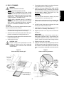
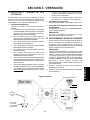
3.
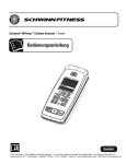
Three-phase Mighty Chef ovens only:
Remove the two screws that hold the rear cover panel
in place; then, remove the cover panel.
Insert the end of the electrical supply through the
connector shown in Figure 3.
Attach the electrical supply wires to their terminal block
connections, as shown in Figure 3.
Secure the supply wires to the floor of the electrical
compartment using the supplied cable clamp. The
wires must not interfere with the drive chain and
sprocket. See Figure 3.
Secure the supply as it passes through the connector
on the outside wall of the oven.
Replace the rear wall of the oven and fasten it in place.
4.
If required by national or local codes, connect an
equipotential ground wire to the lug shown in Figure 3.
The equipotential ground connection must meet all
applicable national and local code requirements.
CAUTION
THE SUPPLIED LEGS AND THE END TRAYS MUST BE
FASTENED IN PLACE BEFORE OPERATING THE OVEN.
Figure 2 - End Tray Installation
1
2
Position tray
Before proceeding with the electrical connection, check
that the electrical supply matches the ovens requirements.
Refer to the serial plate and to the Electrical Specifications
table (in Section 1 of this Manual).
WARNING
ENSURE THAT BOTH THE CIRCUIT BREAKER/
FUSED DISCONNECT AND THE POWER ON/OFF (I/
O) SWITCH ARE IN THE O (OFF) POSITION BEFORE
PROCEEDING.
Wherever the Stacking Kits instructions are different from those
listed below, follow the instructions provided with the Kit.
1.
The toasters power cord and plug provide an electrical
ground connection. A separate equipotential ground connection must also be made if required by national or local
codes.
Consult all applicable national and local codes for further
electrical connection requirements.
Fasten in
place
with screw
Figure 3 - Electrical Connections
3
Wiring
connections
Repeat for
second tray
Terminal
block
C. ELECTRICAL CONNECTION
IMPORTANT
Wiring diagrams for the oven are provided on pages 9-10
of this Manual.
The electrical connection to the oven requires a circuit
breaker/fused disconnect. Consult applicable national and
local code requirements to determine the rating of the
breaker/disconnect. Electrical specifications are listed on
the ovens serial plate and in the Electrical Specifications
table (in Section 1 of this Manual).
(3-phase ovens
only)
Equipotential ground
lug and symbol
(European ovens)
4
Connector
(3-phase ovens only)
Cable clamp
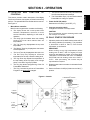
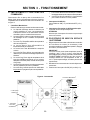
SECTION 3 - OPERATION
AND
FUNCTION
OF
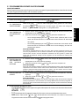
j.
k.
The Up Arrow and Down Arrow keys are used to edit
cook time and temperature settings.
The Preset Menu keys (1-5) are used to select a
Preset Menu to change or operate.
This section provides a basic description of the Mighty
Chef ovens controls, their location, and the functions they
perform. The operator MUST be familiar with the controls.
See Figure 4.
2. Power On/Off (I/O) switch
Switches the oven ON (I) and OFF (O).
1. MenuSelect® controller
Multi-function keypad which contains the following:
3. Conveyor reversing switch
Changes the direction of conveyor travel.
a. The display shows the current preset menu
selection, temperatures, cook time, or error/
service information, depending on the mode of
operation.
CAUTION
Do not operate the conveyor reversing switch while
the conveyor is in motion.
B. DAILY STARTUP PROCEDURE
b. The ready light illuminates when both heating
zones of the oven have reached their set
temperatures.
c.
1. Adjust the position of the draft curtains at the ends of
the cooking chamber (if necessary). This procedure
is described in detail in Part G, Draft Curtain
Adjustment, in this Section.
The Top Temp key displays/sets the top zone
temperature.
d. The Bottom Temp key displays/sets the bottom
zone temperature.
IMPORTANT
When cooking at very high temperatures (either
heating zone is 400°F / 204°C or higher), the oven
should be pre-heated for at least 10 minutes WITH
THE DRAFT CURTAINS IN THE FULLY-LOWERED
POSITION and both heating zones set to 599°F /
315°C. After pre-heating, the curtains may be
repositioned as required.
e. The Cook Time key displays/sets the cook time.
f.
The Ref Temp key displays a reference
temperature for the top or bottom heating zone.
g. The Sngl Pizza key adjusts the temperature of
the top heating zone to properly cook a single
pizza, or the last of a group of pizzas.
h. The Prog key allows reprogramming of the five
Preset Menu Selections.
2. Restore power to the oven at the circuit breaker/fused
disconnect.
i.
3. Switch the Power On/Off (I/O) Switch to the ON (I)
position.
The Prog Override key allows a Preset Menu
Program to be temporarily changed.
Figure 4 - Controls
1. MenuSelect® controller
a
b
2. Power
On/Off (I/O)
switch
c
g
d
h
e
j
f
i
3. Conveyor
reversing
switch
5
k
ENGLISH
A. LOCATION
CONTROLS
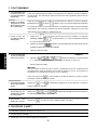
C. OPERATION
ENGLISH
1.
TO PROGRAM A
NEW PRESET MENU
SELECTION:
Perform the procedure in Part E, Programming Preset Menu Selections, in this Section. At least
one menu selection MUST be programmed before the oven can be operated.
2.
TO TEMPORARILY
OVERRIDE A PRESET MENU SELECTION:
Perform the procedure in Part E, Programming Preset Menu Selections, BUT press
instead
(in Steps 3 and 8). Instead of permanently overwriting the menu selection, the new set
of
temperature and cook time settings are only temporary. To cancel the temporary menu selection,
press any preset menu key or disconnect electrical power to the oven.
3.
TO CHOOSE A PRESET MENU SELECTION:
a.
(or any other preset menu key). The display will read
Press
. The number
in the display (1 is shown above) will match the menu key that was pressed (1-5).
b.
Wait for the
light to illuminate. The light will illuminate after both heating zones
reach their set temperatures.
4.
TO COOK A SINGLE
PIZZA, OR THE LAST
OF A GROUP OF PIZZAS:
c.
Load the product onto the conveyor.
a.
Choose a preset menu selection, and wait for the
b.
Press
.
and
light to illuminate.
will alternate in the display. The number in the
display (1 is shown above) will match the current menu selection (1-5).
c.
Load the pizza product onto the conveyor.
IMPORTANT
After 1/2 of the cook time has elapsed, the temperature of the top zone will be automatically
lowered. After the entire cook time has elapsed, the program will return to its normal top zone
temperature.
After
5.
TO VIEW THE SET
TEMPERATURES:
6.
TO VIEW HEATING
ZONE REFERENCE
TEMPERATURES:
7.
TO VIEW THE COOK
TIME:
is pressed, the menu selection cannot be changed until the cook time has elapsed.
or
Press either
Press
+
or
. The top or bottom set temperature will be displayed for 5 seconds.
+
. The top or bottom reference temperature will be displayed
for 5 seconds.
Press
. The cook time will be displayed for 5 seconds.
D. SHUTDOWN PROCEDURE
1.
Switch the Power On/Off (I/O) switch to the OFF (O) position.
2.
Wait for the ovens cooling fan to turn off.
3.
Disconnect electrical power to the oven at the circuit breaker/fused disconnect.
6
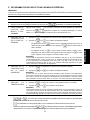
E. PROGRAMMING PRESET MENU SELECTIONS
IMPORTANT
Adding a menu program to the oven will overwrite an existing program. DO NOT enter a new menu program over an
existing program that you wish to keep!
ENGLISH
1. Restore power to the oven at the circuit breaker/fused disconnect.
2. Switch the Power On/Off (I/O) Switch to the ON (I) position.
3. Press and hold
until
4. CHOOSE A MENU
SELECTION TO
PROGRAM
appears in the display.
Press and hold
(or any other preset menu key) until
appears in the display and
begins to flash. The number in the display (1 is shown above) will match the menu key that was
pressed (1-5).
5. SET TOP TEMPERATURE
a.
Press
. The current top set temperature appears in the display.
b.
Press
and
Pressing
as necessary to change the displayed temperature.
once increases the active (flashing) digit by one. This digit rolls over to
its minimum value if
Pressing
is pressed when the digit shows its maximum value.
once causes the next digit to the right to become the active (flashing)
digit. If the far-right digit is flashing when
is pressed, the far-left digit will flash and
become the active digit.
IMPORTANT
The allowed temperature range is 200-599°F (93-315°C). If you program a set temperature between 0°F (or 0°C) and 99°F (37°C), the heater will be set to OFF. If you program a set temperature between 100°F (38°C) and 199°F (92°C), the temperature will automatically change to 200°F
(93°C), the display will flash, and a beep will sound to alert you to the temperature change.
6. SET BOTTOM TEMPERATURE
a.
Press
. The current bottom set temperature appears in the display.
b.
Press
and
as necessary to change the displayed temperature.
IMPORTANT
Unless you are following specific time and temperature instructions, the top and bottom zone
temperatures should be set WITHIN 50°F (28°C) of each other. Greater temperature differences
may cause the hotter zone to heat the cooler zone. This can cause inconsistent cooking results.
7. SET COOK TIME
a.
Press
. The current cook time appears in the display (minutes : seconds).
b.
Press
and
as necessary to change the displayed time.
IMPORTANT
The allowed cook time range is 00:30-15:00. If you program a cook time outside of this range, the
time will change to the closest allowed time (00:30 if your time was too short, or 15:00 if it was too
long). The display will flash, and a beep will sound to alert you to the changed cook time.
8. Press ONE of the following keys:
,
: Turn off Programming Mode. This returns the oven to normal operation.
, or
Any other key except
: Re-enter the top setpoint temperature, bottom set point temperature, or cook time.
or
: Resume operation, but leave Programming Mode active. Other Preset
Menu Selections can be programmed at this time.
7
F. COOKING TIME AND TEMPERATURE
GUIDELINES
G. DRAFT CURTAIN ADJUSTMENT
The draft curtains may need to be repositioned to provide
adequate clearance for some food products. The curtains
should be positioned to prevent drafts into the oven, and
heat loss into the environment.
IMPORTANT
ENGLISH
The cooking times and temperatures shown below are
recommendations only. You should always test each
food product to determine correct time and temperature
settings.
PRODUCT
SET TEMPERATURE
upper
lower
The draft curtains can be removed from the oven to permit
the maximum vertical clearance above the conveyor.
COOK
TIME
Bagel Bites
400°F/204°C
420°F/216°C
5:00
Biscuits
250°F/121°C
335°F/168°C
6:45
Bread Sticks (retherm)
425°F/218°C
475°F/246°C
4:30
Cheese Sticks (frozen)
460°F/238°C
445°F/229°C
6:00
Chicken Nuggets (frozen)
460°F/238°C
445°F/229°C
6:00
Cookies
375°F/191°C
375°F/191°C
9:00
Garlic Bread (retherm)
425°F/218°C
475°F/246°C
2:30
Hamburgers (frozen)
540°F/282°C
540°F/282°C
5:00
Jalapeno Poppers
460°F/238°C
400°F/204°C
6:45
Pizza (fresh), 12 (300mm) dia.
375°F/191°C
480°F/249°C
6:30
Pizza (retherm), slice
425°F/218°C
500°F/260°C
2:15
Pizza (frozen - slacked in
refrigerator 12 hrs. before
cooking), 6-8(150-200mm) dia.
380°F/193°C
430°F/221°C
6:30
Pizza, par baked crust
470°F/243°C
525°F/274°C
6:30
Pretzels (pre-cooked)
505°F/263°C
540°F/282°C
0:45
Sandwiches, open-faced
550°F/288°C
550°F/288°C
0:50
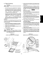
WARNING
BEFORE ADJUSTING THE DRAFT CURTAINS,
SWITCH THE POWER ON/OFF (I/O) SWITCH
TO THE OFF (O) POSITION.
CAUTION - HOT
WHEN REPOSITIONING THE CURTAINS:
WEAR A HEAVY OVEN MITT.
DO NOT REACH INTO THE OVENS
COOKING CHAMBER! See Figure 5.
1. To reposition the draft curtains:
a. Loosen the two screws that hold the draft curtain
in place. See Figure 5.
b. Slide the curtain to the desired clearance above
the conveyor.
c. Tighten the two screws to hold the curtain in place.
d. Repeat these steps for the curtain at the opposite
end of the oven.
2. To remove the curtains from the oven:
a. Remove the two screws that hold the draft curtain
in place.
b. Remove the draft curtain.
c. Repeat these steps for the curtain at the opposite
end of the oven.
Figure 5
Repositioning the draft curtains
DO keep hands outside
of cooking chamber
DO NOT reach inside
cooking chamber
1
2
Loosen
screws
Reposition
curtain
3
8
Tighten
screws
H. DAILY CLEANING
WARNING
WHEN CLEANING THE OVEN:
NEVER USE PRESSURIZED WATER.
NEVER USE A CLEANING SOLUTION OTHER
THAN SOAP AND WATER ON PORTIONS OF THE
OVEN THAT COME INTO CONTACT WITH FOOD
PRODUCTS. THESE AREAS INCLUDE THE
CONVEYOR BELT AND END TRAYS.
6. Clean the end trays USING SOAP AND WATER
ONLY and towel them dry. If necessary, the end trays
can be removed for cleaning by removing the screws
that hold them in place. See Figure 2 (in the
Installation section of this Manual).
IMPORTANT
If the end trays are removed for cleaning, they must
be replaced prior to operating the oven.
NEVER APPLY ENOUGH LIQUID TO STAND IN
PLACE ON THE OVEN. LIQUID INSIDE THE OVEN
WILL CAUSE A SEVERE ELECTRICAL HAZARD
AND MAY OTHERWISE DAMAGE THE OVEN.
7. Slide the end crumb trays out from underneath the
entrance and exit ends of the conveyor. See Figure
6.
8. Lift BOTH ends of the center crumb tray; then, slide
the tray out of either end of the oven.
CAUTION
DO NOT clean your oven using abrasive cleaners or pads.
Both will scratch and dull the finish.
9. Clean all three of the crumb trays using a commercial
oven cleaner. If necessary, towel them dry.
1. With the conveyor running, use a brush to clean any
crumbs off the conveyor into the crumb trays.
10. Replace the center crumb tray in the oven as shown
in Figure 7.
2. Switch the Power On/Off (I/O) switch to the OFF (O)
position, and wait for the cooling fan to turn off.
IMPORTANT
Proper positioning of the center crumb tray is
REQUIRED for proper cooking. Ensure that the tray
is replaced inside the conveyor frame, as shown in
Figure 7, and NOT on the floor of the cooking chamber!
3. Disconnect electrical power to the oven at the circuit
breaker/fused disconnect.
4. Allow the oven to cool.
11. Replace the two end crumb trays.
CAUTION - HOT
DO NOT TOUCH HOT SURFACES ON THE
OVEN, OR REACH INTO THE COOKING
CHAMBER, UNTIL THE UNIT HAS COOLED
THOROUGHLY.
12. Clean the outside of the oven using a damp cloth with
EITHER soap and water OR a stainless steel cleaner.
Use caution to ensure that liquids do not enter the
oven during cleaning, especially when wiping the fan
grill.
Figure 6
End crumb trays and fan grill
Figure 7
Center crumb tray placement
Clean fan grill
using stiff
nylon brush
Conveyor
belt
Support
tab
Slide trays straight out
(trays are underneath both
ends of conveyor)
9
Tray fits
BETWEEN
conveyor belt
and support
tab.
DO NOT
insert tray
on floor of
oven!
ENGLISH
5. Thoroughly clean the fan grill on the front of the oven
using a stiff nylon brush. See Figure 6.
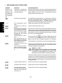
I. DISPLAY MESSAGES AND ERROR CODES
ENGLISH
DISPLAY SHOWS PROBLEM
ACTION
Flashing temperatures or
cook times during programming, and oven
is beeping
Set Temperatures or Cook
Time Outside of Allowed
Range
Re-enter the program using Set Temperatures and Cook Time
within the allowed range. Also, refer to Part E, Programming
Preset Menu Selections, in this Section.
OFF
Heating Element turned off
If the element should be on, re-enter the program using Set
Temperatures within the allowed range. Also, refer to Part E,
Programming Preset Menu Selections, in this Section.
----
No Menu Selection Chosen
Choose or program a preset menu selection.
E-00
E-01
Preset Menu Program Lost
Re-enter the Preset Menu program.
High Ambient Condition
Temperature inside the control enclosure exceeds 65°C.
The oven shuts down, then
beeps continuously.
Check the cooling fan (centered on the front panel of the oven) for
cleanliness and proper operation. If the fan is not running after the
oven heats, or the oven remains in a high ambient condition,
contact your local Authorized Service Agent.
Conveyor Runaway
The conveyor runs at full
speed. The oven shuts down,
then beeps continuously.
Check for the proper speed setting by pressing
Conveyor Loose or Jammed
Conveyor is stopped when
the speed setting is between
0:15 and 15:00.
Switch the Power On/Off (I/O) Switch to the OFF (O) position.
Switch the breaker/fused disconnect to the OFF position. Allow
the oven to cool for at least 30 minutes.
E-02
E-04
. If the speed
setting is correct, and the conveyor continues to run at full speed,
contact your Authorized Service Agent.
CAUTION - HOT
DO NOT ATTEMPT TO FREE A JAMMED CONVEYOR
BELT WHILE THE COOKING CHAMBER IS WARM.
SEVERE INJURY MAY RESULT.
If the conveyor is jammed, free the obstruction from the conveyor
belt. If the conveyor still will not operate properly after the jam is
cleared, OR if the error message appears when the conveyor is
NOT jammed, contact your local authorized service agent.
E-35
E-36
Top Heating Zone Failure
Contact your local authorized service agent.
Bottom Heating Zone Failure
Contact your local authorized service agent.
E-40
Heating Zone Temperature
High Limit
One or both of the heating
zones have reached a temperature greater than 315°C.
Contact your local authorized service agent.
10
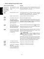
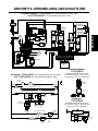
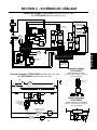
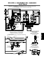
SECTION 4 - ELECTRICAL WIRING DIAGRAMS
Wiring Diagram, TCO21140063 (Domestic & Std. Export 208V)
and TCO21140066 (Domestic & Std. Export 240V)
ENGLISH
L1 N E
TOP HEATER
CC FUSES (2)
5.0A/600V
TC
BOTTOM HEATER
CONTACTOR
MOTOR
PICKUP ASSY
TSTAT
N.C.
FUSE
0.25A
TC
TFRMR
230Vp
12Vs
TFRMR
230Vp
115Vs
TSTAT
VAR
VAR
FUSE
0.5A
N.O.
SSR 1
SSR 2
BLACK
WHITE
FAN
RED
POWER ON/OFF
(I/O) SWITCH
CONVEYOR
REVERSING SWITCH
MENUSELECT®
CONTROLLER
Wiring Diagram,
TCO21140035
(European Export 230V)
Remainder of wiring matches
TCO21140063/0066
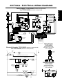
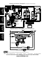
Electrical Schematic, TCO21140063 (Domestic & Std. Export 208V)
and TCO21140066 (Domestic & Std. Export 240V)
N
L1
TSTAT
N.O.
CC FUSES (2)
5.0A/600V
FAN
TSTAT
N.C.
POWER ON/OFF (I/O) SWITCH 2 POLE
C1
C
CC FUSE
5.0A/600V
230Vp
115Vs
RFI
FILTER
230Vp
12Vs
CC FUSE
5.0A/600V
Electrical Schematic,
TCO21140035
0.5A
MENUSELECT® CONTROLLER
CONVEYOR
REVERSING
SWITCH
SSR 1
(European Export 230V)
Remainder of wiring matches
TCO21140063/0066
SSR 2
0.25A
C2
E
M
TOP HEATER 2500W
SSR 2
230Vp
115Vs
SSR 1
BOTTOM HEATER 2500W
RFI FILTER
11
230Vp
12Vs
0.5A
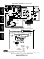
Wiring Diagram, TCO21140077 (European Export 380-400V)
N L1 L2 L3 E
TOP HEATER
page 1
ENGLISH
CC FUSES (2)
5.0A/600V
CONTACTOR
LINE
FILTER
TC
BOTTOM HEATER
TSTAT
FUSE
0.25A
TC
TFRMR
230Vp
12Vs
TFRMR
230Vp
115Vs
MOTOR
PICKUP ASSY
RFI
FILTER
VAR
VAR
N.C.
FUSE
0.5A
DEUTSCH
TSTAT
SSR 1
N.O.
SSR 2
seite 13
BLACK
WHITE
FAN
RED
POWER ON/OFF
(I/O) SWITCH
FRANÇAIS
MENUSELECT®
CONTROLLER
page 25
CONVEYOR
REVERSING SWITCH
Electrical Schematic, TCO21140077 (European Export 380-400V)
TSTAT
N.O.
L2
L3
E
FAN
POWER ON/OFF (I/O) SWITCH 2 POLE
página 37
ESPAÑOL
TSTAT
N.C.
C1
L1
LINE FILTER
N
C2
C
RFI FILTER
CC FUSE
5.0A/600V
C3
C4
CC FUSE
5.0A/600V
230Vp
115Vs
230Vp
12Vs
0.5A
MENUSELECT® CONTROLLER
CONVEYOR
REVERSING
SWITCH
SSR 2
0.25A
SSR 1
M
TOP HEATER 2500W
SSR 2
SSR 1
BOTTOM HEATER 2500W
is a registered trademark of CTX, A Middleby Company. All rights reserved.
CTX
1400 Toastmaster Drive
Elgin, IL 60120
USA
(847)741-3300
Middleby Corp 24-Hour Service Hotline 1-800-238-8444
www.middleby.com
FAX (847)741-4406
TCO2114
Teilenummer 43336
Rev. B V1 5/00
US-Version, Standard- und
europäische Export-Version
Modelle:
TCO21140063
(US- und Standard-Export-Version, 208V)
TCO21140066
(US- und Standard-Export-Version, 240V)
Förderbandofen
Kombinationen:
Einfach-Ofen
Doppel-Ofen (zwei Etagen)
Dreifach-Ofen (drei Etagen)
TCO21140035
(Europäische Export-Version, 230V)
TCO21140077
(Europäische Export-Version, 380-400V)
INSTALLATIONS- UND
BENUTZERHANDBUCH
© 2000 CTX, A Middleby Company
ist eine eingetragene Marke von Middleby Marshall, Inc. Alle Rechte
vorbehalten.
Middleby Cooking Systems Group 1400 Toastmaster Drive Elgin, IL 60120 Tel.: 1-847-741-3300 Fax: 1-847-741-4406
página 37
TM
ESPAÑOL
page 25
FRANÇAIS
Seite 13
DEUTSCH
page 1
ENGLISH
Englisch/DEUTSCH
Französisch/Spanisch
INHALT
WARNUNG: IM FALLE EINES BRANDES
TRENNEN SIE DEN OFEN SOFORT VOM STROMNETZ. DURCH AUSSCHALTEN DER ELEKTRISCHEN
HEIZELEMENTE KANN DER OFEN ABKÜHLEN, WODURCH DER BRAND EINFACHER ZU LÖSCHEN IST.
ABSCHNITT 1
BESCHREIBUNG ....................................... 15
A. Produktmerkmale ............................................ 15
WARNUNG: ZU IHRER EIGENEN SICHERHEIT
LAGERN UND VERWENDEN SIE KEIN BENZIN ODER
ANDERE ENTZÜNDLICHE FLÜSSIGKEITEN ODER
DÄMPFE IN DER UNMITTELBAREN UMGEBUNG
DIESES UND ANDERER GERÄTE.
B. Komponenten .................................................. 15
C. Elektrische Daten ........................................... 15
ABSCHNITT 2
INSTALLATION ........................................... 16
DEUTSCH
WARNUNG
UNSACHGEMÄßE INSTALLATION, EINSTELLUNGEN,
MODIFIKATION ODER WARTUNG KANN ZU SACHSCHÄDEN, VERLETZUNGEN UND TOD FÜHREN. LESEN SIE SICH VOR INSTALLATION ODER WARTUNG
DIESES GERÄTS SORGFÄLTIG DIE ANWEISUNGEN
ZU INSTALLATION, BETRIEB UND WARTUNG DURCH.
A. Installationsoptionen und verfügbare Kits ........ 16
B. Zusammenbau ................................................ 16
C. Elektrischer Anschluss ................................... 16
ABSCHNITT 3
BETRIEB ..................................................... 17
WARNUNG
TRENNEN SIE DEN OFEN VOR REINIGUNGS- UND
WARTUNGSARBEITEN VOM STROMNETZ.
A. Lage und Funktion der Bedienelemente .......... 17
B. Normaler Einschaltvorgang ............................. 17
VORSICHT
Die Verwendung anderer Teile als CTX-Originalteile
enthebt den Hersteller von jeglicher Verpflichtung.
C. Betrieb ............................................................ 18
D. Normaler Ausschaltvorgang ............................ 18
WICHTIGER HINWEIS
Wenden Sie sich für Wartungs- und Reparaturarbeiten an
Ihre Vertragswerkstatt. Dem Ofen liegt ein Verzeichnis
der Vertragswerkstätten bei.
E. Programmieren eigener Garprogramme ........... 19
F. Empfehlungen für Garzeiten und
Temperaturen .................................................. 20
WICHTIGER HINWEIS
CTX (als Hersteller) behält sich jederzeit ankündigungsfreie Änderungen an den technischen Daten und dem
Produktdesign vor. Derartige Weiterentwicklungen begründen keinen Anspruch des Käufers auf entsprechende
Änderungen, Verbesserungen, Erweiterungen oder
Teileaustausch an zuvor gekauften Geräten.
G. Einstellen der Abschlussbleche ...................... 20
H. Tägliche Reinigung .......................................... 21
I.
Meldungen und Fehlercodes ........................... 22
ABSCHNITT 4
VERKABELUNGS- UND SCHALTPLÄNE . 23
DIESES HANDBUCH DIENT ALS NACHSCHLAGEWERK. BEWAHREN SIE ES SORGFÄLTIG AUF.
Dieses Handbuch enthält detaillierte Angaben zu
Installation und Betrieb des Förderbandofens.
Weiterhin enthält es wichtige Informationen, die im
Falle einer Fehlfunktion bei der Diagnose des
Problems helfen können. Dieses Handbuch ist von
großer Bedeutung für den Bediener des Ofens und
sollte daher stets verfügbar sein.
A. Verkabelungs- und Schaltplan:
TCO21140063 (US- und Standard-ExportVersion, 208V) und TCO21140066
(US- und Standard-Export-Version, 240V) ....... 23
B. Verkabelungs- und Schaltplan:
TCO21140035 (Europäische ExportVersion, 230V) ................................................ 23
C. Verkabelungs- und Schaltplan:
TCO21140077 (Europäische ExportVersion, 380-400V) ......................................... 24
© 2000 CTX, A Middleby Company
ist eine eingetragene Marke von CTX, A Middleby Company. Alle Rechte vorbehalten.
CTX 1400 Toastmaster Drive Elgin, IL 60120 USA Tel.: 1-847-741-3300 Fax: 1-847-741-4406
Middleby Corp. 24-Stunden-Service-Hotline: 1-800-238-8444
www.middleby.com
14
A. PRODUKTMERKMALE
B. KOMPONENTEN
Der Förderbandofen Modell TCO2114 Mighty Chef wurde
für das schnelle und einfache Garen, Backen und Grillen
einer Vielzahl von Gerichten mit gleichbleibender Qualität
entwickelt. Der Ofen eignet sich ideal für die Zubereitung
von Pizza, Knoblauchbrot, Cookies, Sandwiches u.v.a.m.
Der Mighty Chef verfügt über die folgenden Produktmerkmale:
Die programmierbare elektronische Steuerung erlaubt
die Auswahl von fünf verschiedenen Garprogrammen.
Das hitzeisolierte Außengehäuse sorgt für erhöhte
Sicherheit.
Das 14 Zoll (356mm) breite Förderband kann in beiden
Laufrichtungen betrieben werden.
Die einstellbaren Abschlussbleche reduzieren das
Eindringen von Zugluft in den Ofen sowie die Abgabe
von Hitze an die Umgebung.
Verschweißte und verstärkte Stahlkonstruktion
Schnelle Installation - es sind keine zusätzlichen
Komponenten erforderlich.
Abbildung 1 zeigt die Position der einzelnen Komponenten.
1-3. Ofen-Steuerung - siehe Abschnitt 3, Betrieb.
4. Krümelbleche (insgesamt 3) - Diese dienen zum
Auffangen der durch das Förderband fallenden Krümel.
Ein zentrales Krümelblech befindet sich unterhalb des
Förderbandes in der Ofenkammer. An BEIDEN Enden
des Förderbandes befindet sich jeweils ein weiteres
Krümelblech.
5. Förderbandendbleche - Diese bieten an den Enden des
Förderbandes zusätzliche Arbeitsflächen für das Beund Entladen des Förderbandes.
6. Förderband - Dieses transportiert die Gerichte
zwischen den oberen und unteren Heizelementen durch
den Ofen.
7. Einstellbare Abschlussbleche (insgesamt 2) - Diese
reduzieren das Eindringen von Zugluft in den Ofen sowie
die Abgabe von Hitze an die Umgebung.
8. Lüfter - Kühlt die internen Komponenten des Ofens.
Abbildung 1 - Komponenten
7. Einstellbare
Abschlussbleche (2)
6. Förderband
1. Hauptschalter (I/O)
2. Förderbandumkehrschalter
5. Förderbandendbleche (2)
8. Lüfter
C. ELEKTRISCHE DATEN
3. MenuSelect®Tastenfeld und
Anzeige
TCO21140063
Betriebsspannung
4. Krümelbleche (3)
TCO21140066
TCO21140035
TCO21140077
208V
240V
230V
380-400V
Netzfrequenz
50/60Hz
50/60Hz
50Hz
50Hz
Phasen
einphasig
einphasig
einphasig
dreiphasig
5,0 kW
5,3 kW
5,0 kW
5,0 kW
24,0 A (gesamt)
22,1 A (gesamt)
21,1 A (gesamt)
Anschlusswert
Strombedarf
L1
Nicht belegt
Nicht belegt
Nicht belegt
0,3 A
L2
Nicht belegt
Nicht belegt
Nicht belegt
10,5 A
L3
Nicht belegt
Nicht belegt
Nicht belegt
10,3 A
Nicht belegt
Nicht belegt
Nicht belegt
N
Informationen zu Kabel und
Stecker
Fest angeschlosse- Fest angeschlosseKabelmetal HO7RN-F-Kabel mit
nes Kabel mit NEMA- nes Kabel mit NEMA- drei 4,0-mm-Leitern und angegos6-30P-Stecker
6-30P-Stecker
senem IEC 309-Stecker, Steckerklassifizierung: 230VAC, 32A
15
10,3 A
Nicht belegt
DEUTSCH
ABSCHNITT 1 - BESCHREIBUNG
ABSCHNITT 2 - INSTALLATION
Wichtiger Hinweis
DER KUNDE IST DAFÜR VERANTWORTLICH, DEM
FRACHTFÜHRER SICHTBARE UND VERBORGENE
SCHÄDEN ZU MELDEN.
A. INSTALLATIONSOPTIONEN UND VERFÜGBARE KITS
Für die Installation von zwei oder drei Öfen übereinander ist
das separat erhältliche Stapel-Kit (Teilenummer
T2114STACK) erforderlich. Bei einem Doppel-Ofen benötigen
Sie ein Kit, bei einem Dreifach-Ofen zwei Kits. Es dürfen
maximal drei Öfen übereinander installiert werden.
1.
DEUTSCH
Wo die dem Stapel-Kit beiliegenden Anweisungen von den
folgenden Anweisungen abweichen, haben die Anweisungen
des Stapel-Kits Vorrang.
WARNUNG
VERGEWISSERN SIE SICH, DASS SOWOHL DER
LEISTUNGS-SCHUTZSCHALTER/DIE SICHERUNG ALS
AUCH DER HAUPTSCHALTER (I/O) AUSGESCHALTET
(STELLUNG O) SIND, BEVOR SIE FORTFAHREN.
B. AUFSTELLUNG
1.
Installation der Füße
a. Legen Sie den Ofen vorsichtig auf die Rückseite. Die
Vorderseite (mit den Bedienelementen) sollte nach
oben weisen.
b. Schrauben Sie die vier Füße an der Unterseite des
Ofens in den dafür vorgesehenen Löchern fest.
Ziehen Sie diese fest an, bis sie sicher sitzen.
2. Installation der Förderbandendbleche
a. Hängen Sie wie in Abbildung 2 dargestellt eines der
Förderbandendbleche in das Ende des Förderbandrahmens ein.
b. Befestigen Sie das Endblech wie in Abbildung 2
dargestellt mit einer der mitgelieferten 8-32x3/8'Schrauben.
c. Wiederholen Sie die Schritte a und b mit dem zweiten
Endblech am entgegen gesetzten Ende des
Förderbandrahmens.
VORSICHT
VOR INBETRIEBNAHME DES OFENS MÜSSEN DIE FÜßE
UND DIE ENDBLECHE MONTIERT WERDEN.
Abbildung 2 - Montage der Endbleche
1
WARNUNG
VERGEWISSERN SIE SICH, DASS ALLE
VERPACKUNGSRESTE AUS DER GARKAMMER DES
OFENS ENTFERNT WURDEN.
2.
3.
2
Bringen Sie das
Blech an
sowie in der Tabelle Elektrische Daten in
Abschnitt 1 dieses Handbuchs.
Der Ofen wird über das Netzkabel und den Netzstecker
geerdet. Sofern aufgrund nationaler oder regionaler
Bestimmungen erforderlich muss außerdem eine
separate Erdverbindung hergestellt werden.
Sofern nationale oder regionale Bestimmungen weitere
Anforderungen an den elektrischen Anschluss stellen,
sind diese zu erfüllen.
Kontrollieren Sie, dass die Stromversorgung den
Anforderungen des Ofens (Spannung, Leistung)
entspricht, bevor Sie mit dem elektrischen Anschluss
fortfahren. Die entsprechenden Informationen finden Sie
auf dem Typenschild sowie in der Tabelle Elektrische
Daten in Abschnitt 1 dieses Handbuchs.
Schrauben Sie
das Blech
fest
4.
Bei einphasig betriebenen Mighty Chef-Öfen:
Stellen Sie sicher, dass eine geeignete Steckdose für
den Stecker des Netzkabels vorhanden ist.
Führen Sie den Stecker des Netzkabel in die Steckdose
ein.
Bei dreiphasig betriebenen Mighty Chef-Öfen:
Entfernen Sie die beiden Schrauben der rückseitigen
Abdeckung. Entfernen Sie dann die Abdeckung.
Führen Sie das Ende des Anschlusskabels durch die
in Abbildung 3 dargestellte Kabeldurchführung.
Schließen Sie wie in Abbildung 3 dargestellt die
einzelnen Leiter des Anschlusskabels am Anschlussblock an.
Fixieren Sie das Anschlusskabel mit Hilfe der
mitgelieferten Kabelschelle am Ofenboden. Achten Sie
darauf, dass das Kabel nicht zwischen Antriebsritzel
und -kette geraten kann (siehe Abbildung 3).
Fixieren Sie das Anschlusskabel in der Kabeldurchführung.
Bringen Sie die Abdeckung wieder an, und schrauben
Sie diese wieder fest.
Sollten nationale oder regionale Bestimmungen dies
erfordern, so schließen Sie eine Erdleitung an den
Erdungsanschluss (siehe Abbildung 3) an. Die
Erdverbindung muss allen zutreffenden nationalen und
regionalen Anforderungen entsprechen.
Abbildung 3 - Elektrischer Anschluss
Zuleitungsanschlüsse
3
Verfahren Sie ebenso
mit dem zweiten Blech
Anschlussblock
C. ELEKTRISCHER ANSCHLUSS
WICHTIGER HINWEIS
Auf den Seiten 23 und 24 dieses Handbuchs finden Sie
die Verkabelungs- und Schaltpläne für den Ofen.
Der elektrische Anschluss des Ofens muss über
Leistungsschutzschalter oder Sicherungen abgesichert
sein. Die Dimensionierung des Schutzschalters/der
Sicherungen ergibt sich aus den anwendbaren
nationalen und lokalen Bestimmungen. Die elektrischen
Anschlusswerte finden Sie auf dem Typenschild des Ofens
(nur dreiphasig betriebene Öfen)
Erdungsanschluss
und -symbol (nur bei
europäischer ExportVersion)
16
Kabeldurchführung (nur
dreiphasig betriebene Öfen)
Kabelschelle
ABSCHNITT 3 BETRIEB
A. LAGE UND FUNKTION DER BEDIENELEMENTE
In diesem Abschnitt finden Sie eine kurze Einführung in
die Bedienelemente des Mighty Chef-Ofens, wo diese liegen
und welche Funktion sie haben. Der Bediener muss mit
diesen Steuerelementen (siehe Abbildung 4) vertraut sein.
Die Taste Prog Override (Programmierung
überschreiben) ermöglicht die vorübergehende
Änderung eines Garprogramms.
j.
Die Pfeil-Auf- und Pfeil-Ab-Tasten dienen zum
Einstellen der Garzeit und Temperatureinstellungen.
k. Die Garprogramm-Tasten (1-5) dienen zur Auswahl
des zu ändernden oder auszuführenden
Garprogramms.
1. MenuSelect®-Steuerung
Multifunktionstastenfeld mit folgenden Elementen:
a. Die Anzeige dient je nach Betriebsart zur Anzeige
des ausgewählten Garprogramms, der
Temperaturen und Garzeiten sowie von Fehler- und
Wartungsinformationen.
3. Förderbandumkehrschalter
Ändert die Laufrichtung des Förderbands.
VORSICHT
Der Förderbandumkehrschalter darf nur bei still
stehendem Förderband betätigt werden.
c. Die Taste Top Temp (Obertemperatur) dient zur
Anzeige und Einstellung der Solltemperatur der
oberen Heizzone.
B. NORMALER EINSCHALTVORGANG
1. Stellen Sie (sofern erforderlich) die Abschlussbleche
an beiden Enden der Garkammer ein. Dieser Vorgang
wird in Teil G dieses Abschnitts, Einstellen der
Abschlussbleche, detailliert beschrieben.
d. Die Taste Bottom Temp (Untertemperatur) dient
zur Anzeige und Einstellung der Solltemperatur
der unteren Heizzone.
e. Die Taste Cook Time (Garzeit) dient zur Anzeige
und Einstellung der Garzeit.
WICHTIGER HINWEIS
Beim Betrieb mit extrem hohen Temperaturen
(mindestens eine der Heizzonen wird über 200°C
betrieben) muss der Ofen mindestens 10 Minuten lang
vorgeheizt werden. Dabei müssen die Abschlussbleche
vollständig abgesenkt und beide Heizzonen auf 315°C
eingestellt sein. Nach dem Vorheizen können die
Abschlussbleche ggf. neu eingestellt werden.
Die Taste Ref Temp (Referenztemperatur) dient
zur Anzeige einer Referenztemperatur für die obere
oder die untere Heizzone.
g. Die Taste Sngl Pizza (Einzelpizza) bewirkt beim
Backen einer einzelnen Pizza oder der letzten aus
einer Reihe von Pizzen eine entsprechende
Anpassung der Temperatur der oberen Heizzone.
2. Schalten Sie den Leistungsschutzschalter oder die
Sicherungen ein.
h. Die Taste Prog (Programmieren) ermöglicht eine
Neuprogrammierung der fünf voreingestellten
Garprogramme.
3. Schalten Sie den Hauptschalter (I/O) ein (I).
Abbildung 4 Bedienelemente
1. MenuSelect®-Steuerung
a
b
2. Hauptschalter
(I/O)
c
g
d
h
e
j
f
i
3. Förderbandumkehrschalter
17
k
DEUTSCH
2. Hauptschalter (I/O)
Zum Ein- (I) und Ausschalten (O) des Ofens.
b. Die Bereitschafts-Kontrollleuchte leuchtet, sobald
beide Heizzonen des Ofens die Solltemperatur
erreicht haben.
f.
i.
C. BETRIEB
1.
PROGRAMMIEREN
EINES NEUEN GARPROGRAMMS:
Detaillierte Informationen zur Programmierung finden Sie in Teil E dieses Abschnitts,
Programmieren eigener Garprogramme. Bevor Sie den Ofen in Betrieb nehmen können, MUSS
mindestens ein Garprogramm programmiert sein.
2.
VORÜBERGEHENDE
ÄNDERUNG EINES
GARPROGRAMMS:
Detaillierte Informationen zur Programmierung finden Sie in Teil E dieses Abschnitts,
Programmieren eigener Garprogramme. Drücken Sie aber in den Schritten 3 und 8 statt der
Taste
die Taste
. Die neu eingestellte(n) Garzeit und Solltemperaturen ändern das
Garprogramm nicht, sondern gelten nur vorübergehend. Zum Aufheben der vorübergehenden
Einstellung drücken Sie eine der Garprogramm-Tasten, oder schalten Sie den Ofen aus.
3.
DEUTSCH
AUSWAHL EINES
GARPROGRAMMS:
a.
(oder eine andere Garprogramm-Taste). Die Anzeige zeigt nun
Drücken Sie die Taste
. Die Ziffer in der Anzeige (im Beispiel 1) gibt an, welches Garprogramm (1-5)
ausgewählt wurde.
b.
Warten Sie, bis die Kontrollleuchte
aufleuchtet. Diese Kontrollleuchte leuchtet
auf, sobald beide Heizzonen des Ofens die Solltemperatur erreicht haben.
4.
BACKEN EINER EINZELNEN PIZZA ODER
DER LETZTEN AUS
EINER REIHE VON
PIZZEN:
c.
Beladen Sie das Förderband mit dem Gargut.
a.
Drücken Sie eine Garprogramm-Taste, und warten Sie, bis die Kontrollleuchte
aufleuchtet.
b.
Drücken Sie die Taste
. Nun erscheint in der Anzeige abwechselnd
und
. Die Ziffer in der Anzeige (im Beispiel 1) gibt an, welches Garprogramm (1-5)
ausgewählt wurde.
c.
Beladen Sie das Förderband mit der Pizza.
WICHTIGER HINWEIS
Nach Ablauf der halben Garzeit wird die Temperatur der oberen Heizzone automatisch abgesenkt.
Nach Ablauf der gesamten Garzeit wird die Temperatur der oberen Heizzone wieder auf den
Sollwert eingestellt.
kann das Garprogramm erst wieder nach Ablauf der Garzeit
Nach dem Drücken der Taste
geändert werden.
5.
6.
7.
KONTROLLE DER
E I N G E S T E L LT E N
SOLLTEMPERATUREN:
KONTROLLE DER
REFERENZTEMPERATUREN:
KONTROLLE
GARZEIT:
DER
oder
Drücken Sie eine der Tasten
. Danach wird für fünf Sekunden die Solltemperatur
für die obere bzw. die untere Heizzone angezeigt.
Drücken Sie eine der Tastenkombinationen
+
oder
+
. Danach wird für
fünf Sekunden die Referenztemperatur für die obere bzw. die untere Heizzone angezeigt.
Drücken Sie die Taste
. Danach wird für fünf Sekunden die Garzeit angezeigt.
D. NORMALER AUSSCHALTVORGANG
1.
Schalten Sie den Hauptschalter (I/O) aus (O).
2.
Warten Sie, bis der Lüfter der Ofens stoppt.
3.
Schalten Sie den Leistungsschutzschalter bzw. die Sicherungen aus.
18
E. PROGRAMMIEREN EIGENER GARPROGRAMME
WICHTIGER HINWEIS
Bei der Programmierung eines neuen Programms wird das vorhandene Programm überschrieben. Achten Sie darauf, dass
Sie keine Programme überschreiben, die Sie behalten möchten.
1. Schalten Sie den Leistungsschutzschalter oder die Sicherungen ein.
2. Schalten Sie den Hauptschalter (I/O) ein (I).
gedrückt, bis in der Anzeige die Meldung
3. Halten Sie die Taste
4. AUSWÄHLEN DES
ZU ÄNDERNDEN
GARPROGRAMMS.
Halten Sie die Taste
die Meldung
erscheint.
(oder eine andere Garprogramm-Taste) gedrückt, bis in der Anzeige
erscheint und zu blinken beginnt. Die Ziffer in der Anzeige (im
5. EINSTELLEN DER
SOLLTEMPERATUR
DER OBEREN HEIZZONE
a.
Drücken Sie die Taste
b.
Solltemperatur für die obere Heizzone angezeigt.
und
die gewünschte Temperatur ein.
Stellen Sie mit Hilfe der Tasten
. Nun wird in der Anzeige die aktuelle Einstellung der
Durch einmalige Betätigung der Taste
wird die aktive (blinkende) Ziffer um eins
erhöht. Hat die Ziffer den Wert 9, so wird sie beim erneuten Drücken der Taste wieder
auf 0 gesetzt.
Durch einmalige Betätigung der Taste
wird die nächste Ziffer rechts aktiviert. Blinkt
bereits die Ziffer der Einerstelle, so wird durch erneute Betätigung die Ziffer der
Hunderterstelle aktiviert.
WICHTIGER HINWEIS
Der zulässige Temperaturbereich ist 93°C bis 315°C. Wenn Sie eine Temperatur zwischen 0°C
und 37°C programmieren, wird die Heizzone deaktiviert. Bei Programmierung eines Wertes
zwischen 38°C und 92°C wird die Temperatur automatisch auf 93°C gesetzt. In diesem Fall
weisen Sie die blinkende Anzeige und ein Signalton auf die automatische Änderung der
Temperatur hin.
6. EINSTELLEN DER
SOLLTEMPERATUR
DER UNTEREN
HEIZZONE
7. EINSTELLEN DER
GARZEIT
a.
. Nun wird in der Anzeige die aktuelle Einstellung der
Drücken Sie die Taste
Solltemperatur für die untere Heizzone angezeigt.
und
die gewünschte Temperatur ein.
b. Stellen Sie mit Hilfe der Tasten
WICHTIGER HINWEIS
Sofern Sie nicht spezielle Vorgaben für Garzeit und Temperaturen haben, sollten die eingestellten
Temperaturen für die obere und die untere Garzone maximal 28°C voneinander abweichen. Bei
größeren Temperaturunterschieden besteht die Gefahr, dass die heißere Zone die kühlere
aufheizt. Dies kann zu unregelmäßigen Garresultaten führen.
a.
Drücken Sie die Taste
angezeigt.
. Nun wird in der Anzeige die aktuelle Garzeit (Minuten : Sekunden)
b. Stellen Sie mit Hilfe der Tasten
und
die gewünschte Garzeit ein.
WICHTIGER HINWEIS
Die Garzeit muss in einem Bereich von 00:30 bis 15:00 liegen. Wenn Sie eine kürzere (längere)
Garzeit programmieren, wird automatisch der zulässige Mindestwert (Höchstwert) eingestellt. In
diesem Fall weisen Sie die blinkende Anzeige und ein Signalton auf die automatische Änderung
der Garzeit hin.
8. Drücken Sie EINE der folgenden Tasten:
,
oder
. : Erneute Programmierung der Solltemperatur für die obere oder die untere Heizzone oder
der Garzeit.
: Deaktivieren des Programmiermodus. Der Ofen kehrt in den normalen Betriebsmodus zurück.
Jede andere Taste außer
oder
: Wiederaufnahme des Betriebs bei weiterhin aktiviertem
Programmiermodus. Nun können Sie weitere Garprogramme programmieren.
19
DEUTSCH
Beispiel 1) gibt an, welches Garprogramm (1-5) ausgewählt wurde.
F. EMPFEHLUNGEN FÜR GARZEITEN UND
TEMPERATUREN
G. EINSTELLEN DER ABSCHLUSSBLECHE
Für manche Gerichte müssen die Abschlussbleche
möglicherweise neu eingestellt werden, damit diese durch
die Ein- und Auslassöffnung passen. Diese Abschlussbleche reduzieren das Eindringen von Zugluft in den Ofen
sowie die Abgabe von Hitze an die Umgebung.
Wird die maximal mögliche Höhe der Öffnungen benötigt,
so können die Abschlussbleche auch ganz entfernt werden.
WARNUNG
SCHALTEN SIE VOR DEM EINSTELLEN DER
ABSCHLUSSBLECHE DEN HAUPTSCHALTER
(I/O) AUS (O).
VORSICHT HEIß
VORSICHTSMAßNAHMEN BEIM EINSTELLEN
DER ABSCHLUSSBLECHE:
LEGEN SIE EINEN DICKEN HITZESCHUTZHANDSCHUH AN..
GREIFEN SIE NICHT IN DIE GARKAMMER
DES OFENS (siehe Abbildung 5).
WICHTIGER HINWEIS
Bei den angegebenen Garzeiten und Temperaturen handelt
es sich um unverbindliche Empfehlungen. Sie sollten
zunächst jedes Gericht testen, um die richtigen Garzeitund Temperatur-Einstellungen zu ermitteln.
GERICHT
SOLLTEMPERATUR GARZEIT
oben
unten
DEUTSCH
Bagels
204°C
216°C
5:00
Brötchen
121°C
168°C
6:45
Brotsticks (aufbacken)
218°C
246°C
4:30
Käsesticks (gefroren)
238°C
229°C
6:00
Chicken Nuggets (gefroren)
238°C
229°C
6:00
Cookies
191°C
191°C
9:00
Knoblauchbrot (aufbacken)
218°C
246°C
2:30
Hamburger (gefroren)
282°C
282°C
5:00
Jalapeno Poppers
238°C
204°C
6:45
Pizza (frisch), 30 cm
Durchmesser
191°C
249°C
6:30
Pizza-Stück (aufbacken)
218°C
260°C
2:15
Pizza (gefroren, bereits seit
193°C
mindestens 12 Stunden im
Gefrierschrank), 15 bis 20 cm
Durchmesser
221°C
6:30
Pizza, gleichmäßige Kruste
243°C
274°C
6:30
Brezeln (vorgebacken)
263°C
282°C
0:45
Sandwiches, offen
288°C
288°C
0:50
1. Einstellen der Abschlussbleche:
a. Lockern Sie die beiden Schrauben des
Abschlussblechs (siehe Abbildung 5).
b. Schieben Sie das Abschlussblech in die
gewünschte Position.
c. Ziehen Sie dann die Schrauben des
Abschlussblechs wieder fest.
d. Wiederholen Sie diese Schritte mit dem zweiten
Abschlussblech am entgegen-gesetzten Ende des
Ofens.
2. Entfernen der Abschlussbleche:
a. Entfernen Sie die beiden Schrauben des
Abschlussblechs.
b. Entfernen Sie das Abschlussblech.
c. Wiederholen Sie diese Schritte mit dem zweiten
Abschlussblech am entgegen gesetzten Ende des
Ofens.
Abbildung 5
Einstellen der Abschlussbleche
Richtig: Bleiben
Sie mit den Händen
außerhalb der Garkammer
Falsch: Greifen Sie nicht
in die Garkammer
1
2
Lockern Sie die
Schrauben
Stellen Sie das
Abschlussblech ein
3
20
Ziehen Sie die
Schrauben
wieder fest
H. Tägliche Reinigung
WARNUNG
VORSICHTSMAßNAHMEN BEIM REINIGEN DES
OFENS:
DER OFEN DARF NICHT ABGESPRITZT WERDEN.
DIE MIT NAHRUNGSMITTELN IN KONTAKT
KOMMENDEN TEILE DES OFENS DÜRFEN NUR
MIT WASSER UND SEIFE GEREINIGT WERDEN.
DAZU GEHÖREN INSBESONDERE DAS
FÖRDERBAND UND DIE ENDBLECHE.
ACHTEN SIE BEI DER REINIGUNG DES OFENS
DARAUF, DASS SIE NICHT SO VIEL FLÜSSIGKEIT
VERWENDEN, DASS DIESE AUF DEM OFEN
VERBLEIBT. FLÜSSIGKEIT IM INNEREN DES
OFENS KANN ZU SCHWERWIEGENDEN
ELEKTRISCHEN UNFÄLLEN UND/ODER ZU EINER
BESCHÄDIGUNG DES OFENS FÜHREN.
VORSICHT
Verwenden Sie zur Reinigung des Ofens unter keinen
Umständen aggressive Reinigungsmittel oder
Scheuerschwämme, da diese die Oberfläche verkratzen
und stumpf machen.
1. Kehren Sie bei laufendem Förderband mit einer Bürste
alle Krümel vom Förderband auf die Krümelbleche.
2. Schalten Sie den Hauptschalter (I/O) aus (O), und
warten Sie, bis der Lüfter stoppt.
3. Schalten Sie den Leistungsschutzschalter bzw. die
Sicherungen aus.
4. Lassen Sie den Ofen abkühlen.
VORSICHT - HEIß
BERÜHREN SIE KEINE HEIßEN FLÄCHEN
DES OFENS, UND GREIFEN SIE NICHT IN DIE
GARKAMMER DES OFENS, BEVOR DER OFEN
VÖLLIG ABGEKÜHLT IST.
7.
8.
9.
10.
WICHTIGER HINWEIS
Wenn Sie die Endbleche zum Reinigen abgenommen
haben, müssen Sie diese vor Wiederinbetriebnahme
des Ofens wieder anbringen.
Schieben Sie die Krümelbleche unter den beiden
Förderbandenden heraus (siehe Abbildung 6).
Heben Sie BEIDE Enden des zentralen Krümelblechs
an, und schieben Sie es an einem Ende aus dem Ofen.
Reinigen Sie alle Krümelbleche mit einem gewerblichen
Ofenreiniger. Trocken Sie sie ggf. ab.
Setzen Sie das zentrale Krümelblech wie in Abbildung
7 dargestellt wieder in den Ofen ein.
WICHTIGER HINWEIS
Für den ordnungsgemäßen Betrieb des Ofens muss
das zentrale Krümelblech unbedingt korrekt eingesetzt
werden. Achten Sie darauf, dass Sie das Krümelblech
wie in Abbildung 7 dargestellt in den Förderbandrahmen
einsetzen und nicht einfach auf den Boden der
Garkammer legen.
11. Setzen Sie die beiden Krümelbleche an den
Förderbandenden wieder ein.
12. Reinigen Sie das Außengehäuse des Ofens mit einem
befeuchteten Tuch (Wasser und Seife ODER
Edelstahlreiniger). Achten Sie sorgfältig (insbesondere
bei der Reinigung des Lüftergitters) darauf, dass bei
der Reinigung keine Flüssigkeit in das Innere des Ofens
gelangt.
Abbildung 6
Seitliche Krümelbleche und Lüftergitter
Abbildung 7
Wiedereinsetzen des zentralen Krümelblechs
Reinigen
Sie das Lüftergitter mit einer
harten Nylonbürste
Förderband
Trageschiene
Ziehen Sie die Bleche
gerade heraus
(an beiden Enden des
Förderbandes befinden
sich Krümelbleche)
21
Das Blech
passt
zwischen das
Förderband
und die
Trageschiene.
Legen Sie
das Blech
KEINESFALLS
einfach auf
den Boden
der Garkammer!
DEUTSCH
5. Reinigen Sie das Lüftergitter an der Vorderseite des
Ofens gründlich mit einer harten Nylonbürste (siehe
Abbildung 6).
6. Reinigen Sie die Endbleche nur mit Wasser und Seife.
Trocken Sie diese anschließend ab. Bei Bedarf können
Sie die Endbleche für die Reinigung abmontieren. Lösen
Sie dafür die diese haltenden Schrauben (siehe
Abbildung 2 im Abschnitt Installation dieses Handbuchs).
I.
MELDUNGEN UND FEHLERCODES
DEUTSCH
ANZEIGE
PROBLEM
VORGEHENSWEISE
Blinkende Temperaturen oder
Garzeiten bei der
Programmierung, der Ofen
gibt Signaltöne
aus
Eingestellte Temperaturen
oder Garzeit außerhalb des
zulässigen Bereichs.
Geben Sie das Programm erneut ein. Achten Sie darauf, dass die
Solltemperaturen und die Garzeit innerhalb des zulässigen Bereichs
liegen. Beachten Sie auch Teil E, Programmieren eigener
Garprogramme, dieses Abschnitts.
OFF
Heizelement ausgeschaltet.
----
Kein Garprogramm ausgewählt
Garprogramm verloren gegangen
Hohe Umgebungstemperatur
Die Temperatur innerhalb des
Gehäuses der Steuerung liegt
über 65°C. Der Ofen schaltet
sich ab und gibt laufend
Signaltöne aus.
Durchgegangenes Förderband
Das Förderband läuft mit
Maximalgeschwindigkeit. Der
Ofen schaltet sich ab und gibt
laufend Signaltöne aus.
Förderband locker oder
verklemmt
Das Förderband stoppt,
obwohl eine Garzeit zwischen
00:15 und 15:00 eingestellt
ist.
Soll das Element eingeschaltet sein, so geben Sie das Programm
erneut ein. Achten Sie darauf, dass die Solltemperaturen innerhalb
des zulässigen Bereichs liegen. Beachten Sie auch Teil E,
Programmieren eigener Garprogramme, dieses Abschnitts.
Wählen oder programmieren Sie ein Garprogramm.
E-00
E-01
E-02
E-04
Geben Sie das Garprogramm neu ein.
Überprüfen Sie, ob der Lüfter (an der Vorderseite des Ofens) nicht
verschmutzt ist und ob er ordnungsgemäß funktioniert. Sollte der
Lüfter nach dem Aufheizen des Ofens nicht anlaufen, oder sollte der
Ofen weiterhin eine hohe Umgebungstemperatur melden, so wenden
Sie sich an Ihre Vertragswerkstatt.
Drücken Sie die Taste
, um die Geschwindigkeitseinstellung
zu überprüfen. Stimmt die Einstellung der Förderbandgeschwindigkeit, und läuft das Förderband weiterhin mit maximaler
Geschwindigkeit, so wenden Sie sich an Ihre Vertragswerkstatt.
Schalten Sie den Hauptschalter (I/O) aus (O). Schalten Sie den
Leistungsschalter/die Sicherung aus (O). Lassen Sie den Ofen
mindestens 30 Minuten lang abkühlen.
VORSICHT - HEIß
VERSUCHEN SIE UNTER KEINEN UMSTÄNDEN, EINE
VERKLEMMUNG DES FÖRDERBANDES ZU BEHEBEN,
SOLANGE DIE GARKAMMER NOCH WARM IST. SIE
KÖNNTEN SCHWERE VERLETZUNGEN ERLEIDEN.
Ist das Förderband verklemmt, so beseitigen Sie die Ursache der
Verklemmung. Läuft das Förderband auch nach Beseitigung der
Verklemmung nicht richtig, oder erscheint die Fehlermeldung bei
einem nicht verklemmten Förderband, so wenden Sie sich an Ihre
Vertragswerkstatt.
E-35
Ausfall der oberen Heizzone
Wenden Sie sich an Ihre Vertragswerkstatt:
E-36
Ausfall der unteren Heizzone
Wenden Sie sich an Ihre Vertragswerkstatt:
E-40
Temperaturüberschreitung
Eine oder beide Heizzonen
haben eine Temperatur über
315°C erreicht.
Wenden Sie sich an Ihre Vertragswerkstatt:
22
ABSCHNITT 4 - VERKABELUNGS- UND SCHALTPLÄNE
Verkabelungsplan: TCO21140063 (US- und Standard-Export-Version, 208V)
und TCO21140066 (US- und Standard-Export-Version, 240V)
L1 N E
Obere Heizelemente
CCSicherungen (2)
5,0 A/600 V
TS
Untere Heizelemente
Verteiler
Sicherung
0,25A
TS
Transformator
230V primär /
12V sekundär
Transformator
230V primär/
115V sekundär
Thermostat
Öffner
DEUTSCH
Motor
Befehlsgeber
Varistor
Varistor
Thermostat
Schließer
Sicherung
0,5 A
Halbleiterrelais 1
Halbleiterrelais 2
schwarz
weiß
Lüfter
rot
Hauptschalter (I/O)
Förderbandumkehrschalter
MenuSelect®Steuerung
Verkabelungsplan:
TCO21140035
(Europäische Export-Version, 230V)
Die restlichen Leitungen entsprechen dem
Verkabelungsplan für TCO21140063/0066
Schaltplan: TCO21140063 (US- und Standard-Export-Version, 208V)
und TCO21140066 (US- und Standard-Export-Version, 240V)
N
L1
Thermostat
Schließer
CCSicherungen (2)
5,0A/600V
Lüfter
Thermostat
Öffner
Hauptschalter (I/O), zweipolig
C1
C
CC-Sicherung
5,0 A/600 V
230 V
primär /
115 V
sekundär
Entstörfilter
230 V primär /
12 V sekundär
CC-Sicherung
5,0 A/600 V
Schaltplan:
TCO21140035
0,5 A
MenuSelect®-Steuerung
Förderbandumkehrschalter
0,25 A
C2
E
M
(Europäische Export-Version, 230 V)
Die restlichen Leitungen entsprechen dem
Schaltplan für TCO21140063/0066
Halbleiter- Halbleiterrelais 1
relais 2
Obere Heizelemente 2500W
Halbleiterrelais 2
230V
primär /
115 V
sekundär
Halbleiterrelais 1
Untere Heizelemente 2500W
Entstörfilter
23
230 V primär /
12 V sekundär
0,5 A
Verkabelungplan: TCO21140077
(Europäische Export-Version, 380-400V)
N L1 L2 L3 E
Obere Heizelemente
page 1
ENGLISH
CCSicherungen (2)
5,0 A/600 V
Verteiler
Leitungsfilter
Entstörfilter
TS
Untere Heizelemente
Befehlsgeber
Transformator
230 V primär /
115 V
sekundär
Motor
Thermostat
Öffner
Sicherung
0,25A
TS
Transformator
230 V primär /
12 V sekundär
Varistor
Varistor
Sicherung
0,5 A
Seite 13
DEUTSCH
Thermostat
Schließer
Halbleiterrelais 1
Halbleiterrelais 2
schwarz
weiß
Lüfter
rot
Hauptschalter (I/O)
FRANÇAIS
page 25
MenuSelect®Steuerung
Förderbandumkehrschalter
Schaltplan: TCO21140077
Thermostat
Schließer
L1
L2
L3
E
Lüfter
Hauptschalter (I/O), zweipolig
C2
C
Entstörfilter
CC-Sicherung
5,0 A/600 V
C3
C4
CC-Sicherung
5,0 A/600 V
230 V
primär /
115 V
sekundär
230 V primär /
12 V sekundär
0,5 A
MenuSelect®-Steuerung
Förderbandumkehrschalter
Halbleiterrelais Halbleiterrelais
1
2
0,25 A
página 37
ESPAÑOL
Thermostat
Öffner
C1
(Europäische Export-Version, 380-400V)
Leitungsfilter
N
M
Obere Heizelemente 2500W
Halbleiterrelais 2
Halbleiterrelais 1
Untere Heizelemente 2500W
ist eine eingetragene Marke von CTX, A Middleby Company. Alle Rechte vorbehalten.
CTX 1400 Toastmaster Drive Elgin, IL 60120 USA Tel.: 1-847-741-3300 Fax: 1-847-741-4406
Middleby Corp. 24-Stunden-Service-Hotline: 1-800-238-8444
www.middleby.com
TCO2114
P/N 43336
Rev. B V1 5/00
Exportation USA, Std.,
et Europe
Modèles :
TCO21140063 (Exportation USA & std., 208 V)
TCO21140066 (Exportation USA & std., 240 V)
TCO21140035 (Exportation Europe, 230 V)
TCO21140077 (Exportation Europe, 380-400 V)
Four tunnel
Combinaisons :
Four unique
Double four (superposition de deux éléments)
Triple four (superposition de trois éléments)
MANUEL
D'INSTALLATION
ET DE FONCTIONNEMENT
© 2000 CTX, une société Middleby
est une marque déposée par Middleby Marshall, Inc. Tous droits réservés.
Middleby Cooking Systems Group 1400 Toastmaster Drive Elgin, IL 60120 (847)741-3300 FAX (847)741-4406
página 37
TM
ESPAÑOL
page 25
FRANÇAIS
seite 13
DEUTSCH
page 1
ENGLISH
Anglais/Allemand
FRANÇAIS/Espagnol
SOMMAIRE
AVERTISSEMENT : EN CAS D'INCENDIE
Débranchez IMMÉDIATEMENT le four de sa source
électrique. La mise hors service des éléments de
chauffage électrique permet un refroidissement de
l'unité, et par conséquent une maîtrise plus aisée du feu.
SECTION 1
DESCRIPTION ............................................ 27
A. Caractéristiques .............................................. 27
AVERTISSEMENT : POUR VOTRE SÉCURITÉ
NE STOCKEZ PAS ET N'UTILISEZ PAS D'ESSENCE
OU AUTRES PRODUITS INFLAMMABLES
À PROXIMITÉ DE CET APPAREIL OU
DE TOUT AUTRE ÉQUIPEMENT.
B. Emplacement et fonction des composants ..... 27
C. Spécifications électriques ............................... 27
SECTION 2
INSTALLATION ........................................... 28
AVERTISSEMENT
UNE INSTALLATION, UN RÉGLAGE, UNE
MODIFICATION, UN ENTRETIEN OU UNE
MAINTENANCE INAPPROPRIÉS PEUVENT
ENTRAINER DES DÉGÂTS MATÉRIELS, DES
BLESSURES CORPORELLES GRAVES, VOIRE
MORTELLES. LISEZ ATTENTIVEMENT LES
INSTRUCTIONS D'INSTALLATION ET DE
FONCTIONNEMENT AVANT DE METTRE EN
SERVICE OU D'ENTRETENIR CET ÉQUIPEMENT.
A. Options d'installation et disponibilité du kit ..... 28
B. Assemblage .................................................... 28
C. Connexions électriques ................................... 28
SECTION 3
FONCTIONNEMENT ................................... 29
FRANÇAIS
AVERTISSEMENT
DÉBRANCHEZ LE FOUR DE SA SOURCE
D'ALIMENTATION ÉLECTRIQUE AVANT UN
NETTOYAGE OU UNE RÉPARATION.
A. Emplacement et fonction des commandes ..... 29
ATTENTION
L'utilisation de pièces autres que les pièces CTX
d'origine décharge le fabricant de toute responsabilité.
D. Procédure d'arrêt ............................................. 30
B. Procédure de mise en service quotidienne ...... 29
C. Fonctionnement .............................................. 30
E. Programmation des sélections
par menus prédéfinis ....................................... 31
IMPORTANT
Contactez votre réparateur agréé pour effectuer la
maintenance et les réparations. Une liste de sociétés
de réparation est fournie avec votre équipement.
F. Temps de cuisson et température ................... 32
G. Positionnement des rideaux ............................ 32
H. Nettoyage quotidien ........................................ 33
IMPORTANT
CTX (fabricant) se réserve le droit de modifier les
spécifications et la conception du produit sans
préavis. Ces révisions n'impliquent pas, pour
l'acheteur, l'obtention de modifications, améliorations,
ajouts ou remplacements correspondants en ce qui
concerne l'équipement acheté préalablement.
I.
Affichage des messages et codes d'erreur ...... 34
SECTION 4
DIAGRAMMES DE CÂBLAGE .................... 35
A. Diagramme de câblage et schéma :
TCO21140063 (Exportation USA & Std.,
208 V) et TCO21140066 (Exportation
USA & Std., 240 V) ........................................ 35
B. Diagramme de câblage et schéma :
TCO21140035 (Exportation Europe, 230 V) ..... 35
CONSERVEZ CE MANUEL POUR LES
RÉFÉRENCES FUTURES
Ce manuel fournit des informations détaillées relatives
à l'installation et au fonctionnement de votre four tunnel.
Il contient également des informations permettant d'aider
l'opérateur à diagnostiquer les problèmes en cas de
défaut de fonctionnement. Ce manuel est un outil
important qu'il convient d'avoir sous la main.
C. Diagramme de câblage et schéma :
TCO21140077 (Exportation Europe,
380-400 V) ...................................................... 36
© 2000 CTX, une société Middleby
est une marque déposée par CTX, une société Middleby. Tous droits réservés.
CTX
1400 Toastmaster Drive
Elgin, IL 60120
USA
(847)741-3300
FAX (847)741-4406
Middleby Corp Assistance téléphonique 24 heures sur 24 1-800-238-8444
www.middleby.com
26
SECTION 1 - DESCRIPTION
A. CARACTÉRISTIQUES
B. EMPLACEMENT ET FONCTION DES
COMPOSANTS
FRANÇAIS
Le four tunnel modèle TCO2114 Mighty Chef est conçu pour
cuisiner, cuire et griller rapidement et facilement une variété de
Voir la figure 1 pour l'emplacement de ces composants.
produits alimentaires avec une qualité et des résulats parfaits.
1-3. Commandes du four - voir section 3, Fonctionnement.
Le four est idéal pour la préparation de pizzas, pains grillés
4. Ramasse-miettes (3 au total) - Récupère les miettes
à l'ail, cookies, sandwiches et autres produits alimentaires.
qui passent sur le tapis. Un ramasse-miettes central
Les caractéristiques du Mighty Chef comprennent :
est situé en dessous du centre du tapis. Un ramasse Un contrôleur électronique, programmable qui permet
miettes externe est situé en dessous de CHAQUE
jusqu'à 5 sélections par menus prédéfinis
extrémité du tapis.
Des parois extérieures froides pour une sécurité accrue
5. Plateaux externes - Fournissent un espace
Une bande transporteuse de 356 mm de largeur qui
supplémentaire de chargement/de sortie aux extrémités
peut être facilement installée pour fonctionner dans
du tapis.
l'une ou l'autre direction
6. Tapis - Transporte le produit à travers le four, entre les
Des rideaux flexibles réglables qui réduisent les tirages
éléments chauffants supérieur et inférieur.
dans le four et empêchent la perte de chaleur dans
7. Rideaux flexibles réglables (2 au total) - Réduisent les
l'environnement
tirages dans le four et empêchent la perte de chaleur
dans l'environnement.
Une construction en acier inoxydable soudé et renforcé
8. Ventilateur - Refroidit les composants internes du four.
Une installation de comptoir rapide - aucun composant
supplémentaire n'est requis
Figure 1 - Emplacement des composants
7. Rideaux réglables (2)
6. Tapis
1. Interrupteur
On/Off (I/O)
2. Interrupteur
d'inversion du
défilement du tapis
8. Ventilateur
5. Plateaux
externes (2)
3. Clavier et affichage
MenuSelect®
4. Ramasse-miettes (3)
C. SPÉCIFICATIONS ÉLECTRIQUES
Tension de fonctionnement
Fréquence
Phase
Calibre kW
Appel de courant
TCO21140063
TCO21140066
TCO21140035
TCO21140077
208 V
240 V
230 V
380-400 V
50/60 Hz
50/60 Hz
50 Hz
50 Hz
1 Ph
1 Ph
1 Ph
3 Ph
5,0 kW
5,3 kW
5,0 kW
5,0 kW
24,0 A (total)
22 A (total)
21,1 A (total)
L1
S/O
S/O
S/O
0,3 A
L2
S/O
S/O
S/O
10,5 A
L3
S/O
S/O
S/O
10,3 A
N
Cordon/prise
S/O
S/O
S/O
10,3 A
Cordon
prise NEMA
6-30P
Cordon
prise NEMA
6-30P
Cordon type Kabelmetal HO7RN-F
avec conducteurs 3 x 4,0 mm
et prise moulée IEC 309
Prise : 230 V AC, 32 A
S/O
27
SECTION 2 - INSTALLATION
IMPORTANT
IL EST DE LA RESPONSABILITÉ DU CLIENT DE SIGNALER
À LA SOCIÉTÉ DE TRANSPORT TOUT DOMMAGE APPARENT
OU NON APPARENT.
A. OPTIONS D'INSTALLATION & DISPONIBILITÉ
DU KIT
Si l'installation requiert la superposition de deux ou trois fours,
vous devez utiliser le kit de superposition vendu séparément
(P/N T2114STACK). Un kit est nécessaire pour une
superposition de deux éléments, tandis que deux kits sont
nécessaires pour la superposition de trois éléments.
La superposition de plus de trois fours n'est pas autorisée.
1.
Le cordon et la prise du grilloir fournissent une connexion
de masse. Une connexion de masse équipotentielle
séparée doit également exister si les réglementations
nationales ou locales le requièrent.
Consultez toutes les réglementations nationales et locales
applicables pour les exigences en matière de connexions
électriques supplémentaires.
Avant d'entreprendre les connexions, vérifiez si
l'alimentation électrique est adaptée au four. Consultez la
plaque de série et le tableau des Spécifications électriques
(section 1 de ce manuel).
Lorsque les instructions du kit diffèrent de celles énoncées
ci-dessous, suivez les instructions fournies avec le kit.
AVERTISSEMENT
AVANT DE CONTINUER, ASSUREZ-VOUS QUE LE
DISJONCTEUR/SECTIONNEUR ET L'INTERRUPTEUR
ON/OFF (I/O) SONT POSITIONNÉS SUR « O » (OFF).
B. ASSEMBLAGE
AVERTISSEMENT
ASSUREZ-VOUS QU'IL N'Y A PLUS AUCUN RESTE
D'EMBALLAGE À L'INTÉRIEUR DE LA CHAMBRE DE
CUISSON DU FOUR.
1.
FRANÇAIS
Installation des pieds
a. Inclinez le four sur la face arrière avec précaution. Il
convient de toujours diriger la face avant (contrôleur)
vers le haut.
b. Insérez les quatre pieds dans les trous situés sous
le four. Serrez-les jusqu'à fixation complète.
2. Installation des plateaux externes
a. Encastrez l'un des plateaux externes sur la plaque à
l'extrémité du cadre du tapis, comme le montre la
figure 2.
b. Fixez le plateau externe avec l'une des vis 8-32x3/8"
fournies, comme le montre la figure 2.
c. Répétez les étapes précédentes pour installer le
second plateau externe à l'extrémité opposée du
cadre du tapis.
ATTENTION
LES PIEDS ET LES PLATEAUX EXTERNES FOURNIS
DOIVENT ÊTRE FIXÉS AVANT LA MISE EN SERVICE DU FOUR.
Figure 2 - Installation des plateaux externes
1
2.
3.
2
Positionnez
le plateau
4.
Fixez avec
une vis
Fours Mighty Chef monophasés uniquement :
Vérifiez si la prise de courant appropriée est
disponible pour le cordon d'alimentation.
Insérez le cordon d'alimentation dans la prise.
Fours Mighty Chef triphasés uniquement :
Retirez les deux vis qui maintiennent le panneau
arrière puis ôtez ce dernier.
Insérez l'extrémité de l'alimentation électrique par le
connecteur présenté à la figure 3.
Fixez les câbles d'alimentation électrique aux
raccordements, comme le montre la figure 3.
Fixez les câbles d'alimentation à la base du
compartiment électrique à l'aide du collier de câble
fourni. Les câbles ne doivent pas être en contact avec
la chaîne et la roue d'entraînement. Voir la figure 3.
Fixez le câble d'alimentation, au niveau de son
passage à travers le connecteur, sur la paroi externe
du four.
Replacez le panneau arrière du four et fixez-le.
Si les réglementations nationales ou locales l'exigent,
connectez un fil de masse équipotentielle à la prise
présentée sur la figure 3. La connexion de masse
équipotentielle doit satisfaire toutes les exigences des
réglementations nationales et locales applicables.
Figure 3 - Connexions électriques
3
Connexions
Répétez l'opération pour
le second plateau
Boîtier de
raccordement
C. CONNEXIONS ÉLECTRIQUES
(fours triphasés
uniquement)
IMPORTANT
Les diagrammes de câblage du four sont fournis aux
pages 9-10 de ce manuel.
La connexion électrique au four requiert un disjoncteur/
sectionneur. Consultez les exigences des réglementations
nationales et locales applicables pour la détermination du
calibre du disjoncteur/sectionneur. Les spécifications
électriques sont énoncées sur la plaque de série du four et
dans le tableau des Spécifications électriques (section 1
de ce manuel).
Prise et symbole masse
équipotentielle (fours
européens)
Connecteur (fours triphasés
uniquement)
28
Collier de câble
SECTION 3 - FONCTIONNEMENT
j.
Les touches fléchées sont utilisées pour modifier
les réglages de temps de cuisson et de température.
k. Les touches de menu prédéfini (1-5) sont utilisées
pour modifier ou lancer un menu prédéfini.
A. EMPLACEMENT ET FONCTIONS DES
COMMANDES
Cette section offre un aperçu des commandes du four
Mighty Chef, de leur emplacement et de leurs fonctions.
L'opérateur DOIT se familiariser avec les commandes. Voir
la figure 4.
2. Interrupteur On/Off (I/O)
Permet d'allumer ON (« I ») et d'éteindre OFF (« O »)
le four.
1. Contrôleur MenuSelect®
Clavier multifonction qui contient les éléments suivants :
a. Le dispositif d'affichage résente la sélection par
menus prédéfinis en cours, les températures,
le temps de cuisson ou les informations d'erreur/
d'entretien, selon le mode de fonctionnement.
b. Le témoin READY s'allume lorsque les deux zones
de chauffage du four ont atteint la température
prédéfinie.
c. La touche Top Temp affiche/définit la température
de la zone supérieure.
d. La touche Bottom Temp affiche/définit la
température de la zone inférieure.
e. La touche Cook Time affiche/définit le temps de
cuisson.
f. La touche Ref Temp affiche une température de
référence pour la zone de chauffage supérieure ou
inférieure.
g. La touche Sngl Pizza règle la température de la
zone de chauffage supérieure pour la cuisson
adéquate d'une seule pizza, ou de la dernière pizza
d'un groupe.
h. La touche Prog permet une nouvelle programmation
des cinq sélections par menus prédéfinis.
i. La touche Prog Override permet une modification
temporaire d'un programme par menus prédéfinis.
3. Interrupteur d'inversion du défilement du tapis
Inverse la marche du tapis transporteur.
ATTENTION
N'activez pas l'interrupteur d'inversion lorsque le tapis
est en mouvement.
B. PROCÉDURE DE MISE EN SERVICE
QUOTIDIENNE
IMPORTANT
Lors d'une cuisson à très haute température (zone de
chauffage : 400 °F / 204 °C ou plus), le four doit être
préchauffé pendant au moins 10 minutes, LES RIDEAUX
COMPLÈTEMENT BAISSÉS et les deux zones de
chauffage définies sur une température de 599 °F /
315 °C. Après le préchauffage, les rideaux peuvent être
repositionnés.
2. Remettez le four sous tension au niveau du disjoncteur/
sectionneur.
3. Positionnez l'interrupteur On/Off (I/O) sur ON (« I »).
Figure 4 - Commandes
1. Contrôleur MenuSelect®
a
b
2. Interrupteur
On/Off (I/O)
c
g
d
h
e
j
f
i
3. Interrupteur
d'inversion
du défilement
29
k
FRANÇAIS
1. Réglez la position des rideaux flexibles aux extrémités
de la chambre de cuisson (si nécessaire). Cette
procédure est décrite en détail dans la partie G, Réglage
des rideaux, de cette section.
C. FONCTIONNEMENT
1. P R O G R A M M AT I O N
D'UNE NOUVELLE SÉLECTION PAR MENUS
PRÉDÉFINIS :
2. R E M P L A C E M E N T
TEMPORAIRE D'UNE
SÉLECTION PAR MENUS PRÉDÉFINIS :
Suivez la procédure décrite à la partie E, Programmation des sélections par menus prédéfinis,
de cette section. Une sélection par menus au moins DOIT être programmée avant la mise en
service du four.
Suivez la procédure décrite à la partie E, Programmation des sélections par menus prédéfinis,
au lieu de
MAIS appuyez sur
(étapes 3 et 8). Les nouveaux réglages de température
et de temps de cuisson ne sont que temporaires ; la sélection par menus n'est pas remplacée
définitivement. Pour annuler la sélection par menus temporaire, appuyez sur une touche
quelconque de menu prédéfini ou débranchez le four.
3. CHOIX D'UNE SÉLECTION PAR MENUS
PRÉDÉFINIS :
a.
Appuyez sur
(ou une touche quelconque de menu prédéfini). Le dispositif
. Le numéro affiché (« 1 » dans cet exemple) correspond
d'affichage indique
à la touche sélectionnée (1-5).
b.
Attendez que le témoin
s'allume. Le témoin s'allume une fois que les deux zones de
chauffage ont atteint leur température prédéfinie.
FRANÇAIS
4. CUISSON D'UNE PIZZA
OU DE LA DERNIÈRE
PIZZA D'UN GROUPE :
c.
Placez le produit sur le tapis.
a.
Choisissez une sélection par menus prédéfinis et attendez que le témoin
b.
Appuyez sur
.
et
s'allume.
s'affichent en alternance. Le numéro affiché
(« 1 » dans cet exemple) correspond à la sélection par menus en cours (1-5).
c.
Placez la pizza sur le tapis.
IMPORTANT
Une fois la moitié du temps de cuisson écoulé, la température de la zone supérieure baisse
automatiquement. Après écoulement de la totalité du temps de cuisson, le programme se
repositionne sur la température normale de la zone supérieure.
, il n'est possible de modifier la sélection par menus qu'après
Après avoir appuyé sur
écoulement complet du temps de cuisson.
5. AFFICHAGE DES TEMPÉRATURES PRÉDÉFINIES :
6. AFFICHAGE DES TEMPÉRATURES DE RÉFÉRENCE DES ZONES
DE CHAUFFAGE :
7. AFFICHAGE
DU
TEMPS DE CUISSON :
Appuyez sur
ou sur
.La température prédéfinie de la zone supérieure ou inférieure
s'affiche pendant 5 secondes.
Appuyez sur
+
ou sur
+
. La température de référence de la zone supérieure
ou inférieure s'affiche pendant 5 secondes.
Appuyez sur
. Le temps de cuisson s'affiche pendant 5 secondes.
D. PROCÉDURE D'ARRÊT
1.
Positionnez l'interrupteur On/Off (I/O) sur OFF (« O »).
2.
Attendez l'arrêt du ventilateur.
3.
Débranchez le four au niveau du disjoncteur/sectionneur.
30
E. PROGRAMMATION DES SÉLECTIONS PAR MENUS PRÉDÉFINIS
IMPORTANT
L'ajout d'un programme de menu supprimera un programme existant. N'EFFECTUEZ PAS une nouvelle programmation
de menu sur un programme existant que vous souhaitez conserver !
1. Remettez le four sous tension au niveau du disjoncteur/sectionneur.
2. Positionnez l'interrupteur On/Off (I/O) sur ON (« I »).
3. Appuyez sur la touche
4. CHOIX D'UNE SÉLECTION
PAR
MENUS À PROGRAMMER
5. RÉGLAGE DE LA
T E M P E R AT U R E
DE LA ZONE SUPÉRIEURE
et maintenez-la jusqu'à ce que
apparaisse sur le dispositif d'affichage.
Appuyez sur la touche
(ou une touche quelconque de menu prédéfini) et maintenez-la
jusqu'à ce que
apparaisse et clignote sur le dispositif d'affichage. Le numéro
affiché (« 1 » dans cet exemple) correspond à la touche sélectionnée (1-5).
a.
Appuyez sur
. La température en cours de la zone supérieure apparaît.
b.
Appuyez sur
et sur
pour modifier la température affichée.
En appuyant une fois sur
, le chiffre « actif » (clignotant) augmente d'une unité. Ce
chiffre reprend sa valeur minimale si vous appuyez sur
lorsque le chiffre affiche sa
En appuyant une fois sur
, le chiffre suivant de droite devient le chiffre « actif »
(clignotant). Si le chiffre le plus à droite clignote lorsque vous appuyez sur
, le chiffre
le plus à gauche se met à clignoter et devient le chiffre « actif ».
IMPORTANT
La fourchette de températures autorisée est de 200-599 °F (93-315 °C). Si vous programmez
une température entre 0 °F (ou 0 °C) et 99 °F (37 °C), l'élément chauffant sera positionné sur OFF.
Si vous programmez une température entre 100 °F (38 °C) et 199 °F (92 °C), celle-ci sera
automatiquement définie sur 200 °F (93 °C), le dispositif d'affichage clignotera et un signal
sonore annoncera la modification de température.
6. RÉGLAGE DE LA
T E M P E R AT U R E
DE
LA
ZONE
INFÉRIEURE
7. RÉGLAGE
DU
TEMPS DE CUISSON
a.
Appuyez sur
. La température en cours de la zone inférieure apparaît.
b.
Appuyez sur
et sur
pour modifier la température affichée.
IMPORTANT
À moins que vous ne suiviez des instructions spécifiques quant au temps et à la température,
l'écart entre la température de la zone supérieure et de la zone inférieure ne doit pas excéder
50 °F (28 °C). Dans le cas de différences de températures plus importantes, la zone plus chaude
peut réchauffer la zone plus froide. Dans ce cas précis, la cuisson peut ne pas être homogène.
a.
Appuyez sur
. Le temps de cuisson en cours apparaît (minutes : secondes).
b.
Appuyez sur
et sur
pour modifier le temps affiché.
IMPORTANT
La fourchette de temps de cuisson autorisée est 00:30-15:00. Si vous programmez un temps de
cuisson qui se situe en dehors de cette fourchette, celui-ci sera adapté sur le temps autorisé le
plus proche (00:30 si le temps choisi est trop court ou 15:00 si le temps choisi est trop long). Le
dispositif d'affichage clignote et un signal sonore annonce la modification du temps de cuisson.
8. Appuyez sur L'UNE des touches suivantes :
,
, ou
: pour entrer de nouveau la température prédéfinie de la zone supérieure, la température
prédéfinie de la zone inférieure ou le temps de cuisson.
pour désactiver le mode programmation. Le four repasse en mode de fonctionnement normal.
Une touche quelconque à l'exception de
ou
: pour reprendre le fonctionnement, mais le Mode programmation
demeure actif. À ce moment, il est possible de programmer d'autres sélections par menus prédéfinis.
31
FRANÇAIS
valeur maximale.
F. INSTRUCTIONS RELATIVES AU TEMPS
DE CUISSON ET À LA TEMPÉRATURE
G. POSITIONNEMENT DES RIDEAUX
Il peut s'avérer nécessaire de repositionner les rideaux afin
d'obtenir un espace adéquat pour certains produits
alimentaires. Il convient de positionner les rideaux afin
d'éviter les tirages dans le four et les pertes de chaleur
dans l'environnement.
Il est possible de retirer les rideaux pour bénéficier de la
hauteur maximale au-dessus du tapis.
IMPORTANT
Les temps de cuisson et les températures présentés
ci-dessous sont uniquement des recommandations. Il
convient d'essayer systématiquement chaque produit
alimentaire afin de déterminer les réglages adéquats de
temps et de température.
PRODUCT
AVERTISSEMENT
AVANT DE RÉGLER LES RIDEAUX,
POSITIONNEZ L'INTERRUPTEUR ON/OFF (I/O)
SUR OFF (« O »).
TEMPÉRATURE
TEMPS DE
supérieure inférieure CUISSON
FRANÇAIS
Bagel Bites
204,44°C/204°C 215,56°C/216°C
5:00
Biscuits
121,11°C/121°C 168,33°C/168°C
6:45
Pains baguette (à réchauffer)
218,33°C/218°C 246,11°C/246°C
4:30
Bâtonnets de fromage (congelés)
237,78°C/238°C 229,44°C/229°C
6:00
Beignets de poulet (congelés)
237,78°C/238°C 229,44°C/229°C
6:00
Cookies
190,56°C/191°C 190,56°C/191°C
9:00
Pain à l'ail (à réchauffer)
218,33°C/218°C 246,11°C/246°C
2:30
Hamburgers (congelés)
282,22°C/282°C 282,22°C/282°C
5:00
Jalapeno Poppers
237,78°C/238°C 204,44°C/204°C
6:45
Pizza (fraîche), diam. 12" (300 mm). 190,56°C/191°C 248,89°C/249°C
6:30
Pizza (à réchauffer), quartier
218,33°C/218°C 260,00°C/260°C
2:15
Pizza (congelée - placée dans
le réfrigérateur 12 heures
avant la cuisson),
diam. 6-8" (150-200 mm).
193,33°C/193°C 221,11°C/221°C
6:30
Pizza, croûte épaisse
243,33°C/243°C 273,89°C/274°C
6:30
Bretzels (précuites)
262,78°C/263°C 282,22°C/282°C
0:45
Sandwiches, canapé
550 °F/288 °C 550 °F/288 °C
0:50
ATTENTION - SURFACE CHAUDE
LORS DU REPOSITIONNEMENT DES RIDEAUX :
PORTEZ UN GANT DE CUISINE RÉSISTANT
N'INTRODUISEZ PAS LA MAIN DANS LA
CHAMBRE DE CUISSON ! Voir la figure 5.
1. Repositionnement des rideaux :
a. Desserrez les deux vis de fixation qui maintiennent
le rideau. Voir la figure 5.
b. Faites glisser le rideau jusqu'à obtention de
l'espace désiré au-dessus du tapis.
c. Serrez les deux vis de fixation qui maintiennent le
rideau.
d. Répétez ces étapes pour le rideau situé à
l'extrémité opposée du four.
2. Retrait des rideaux :
a. Retirez les deux vis de fixation qui maintiennent le
rideau.
b. Ôtez le rideau.
c. Répétez ces étapes pour le rideau situé à
l'extrémité opposée du four.
Figure 5
Repositionnement des rideaux
GARDEZ les mains
en dehors de la chambre
de cuisson.
N'INTRODUISEZ PAS
les mains à l'intérieur de la chambre de cuisson
1
2
Vis
deserrées
Repositionnement
du rideau
3
32
Vis
serrées
5. Nettoyez soigneusement la grille du ventilateur sur la
face avant du four à l'aide d'une brosse en nylon dur.
Voir la figure 6.
H. NETTOYAGE QUOTIDIEN
AVERTISSEMENT
DURANT LE NETTOYAGE DU FOUR :
N'UTILISEZ JAMAIS D'EAU SOUS PRESSION.
N'UTILISEZ JAMAIS DE DÉTERGENT AUTRE QUE
DU SAVON ET DE L'EAU SUR LES PARTIES DU
FOUR EN CONTACT AVEC LA NOURRITURE. CES
ZONES COMPRENNENT LA BANDE TRANSPORTEUSE ET LES PLATEAUX EXTERNES.
IMPORTANT
Si les plateaux externes sont démontés pour le
nettoyage, ils doivent être replacés avant la mise en
service du four.
NE LAISSEZ JAMAIS DE LIQUIDE STAGNER DANS
LE FOUR. UN LIQUIDE À L'INTERIEUR DU FOUR
PEUT ENDOMMAGER L'APPAREIL ET ENTRAÎNER
UN RISQUE D'ÉLECTROCUTION IMPORTANT.
7. Faites glisser les ramasse-miettes externes situés
sous les extrémités d'entrée et de sortie du tapis. Voir
la figure 6.
ATTENTION
NE NETTOYEZ PAS votre four avec des produits de
nettoyage ou des tissus abrasifs. Ceux-ci peuvent rayer et
ternir la surface.
8. Soulevez LES DEUX extrémités du ramasse-miettes
central puis glissez-le par l'un des deux côtés du four.
9. Nettoyez les trois ramasse-miettes à l'aide d'un produit
nettoyant spécial fours. Essuyez-les si nécessaire.
1. Mettez en marche le tapis et évacuez les miettes sur
les ramasse-miettes à l'aide d'une brosse.
10. Replacez le ramasse-miettes central dans le four
comme le montre la figure 7.
2. Positionnez l'interrupteur On/Off (I/O) sur OFF (« O »)
et attendez l'arrêt du ventilateur.
IMPORTANT
Un positionnement correct du ramasse-miettes central
est NÉCESSAIRE à l'obtention d'une cuisson adéquate.
Assurez-vous que le ramasse-miettes est repositionné
à l'intérieur du cadre du tapis, comme le montre la figure
7, et NON sur la base de la chambre de cuisson !
3. Débranchez le four au niveau du disjoncteur/
sectionneur.
4. Attendez le refroidissement du four.
11. Replacez les deux ramasse-miettes externes.
ATTENTION - SURFACE CHAUDE
NE TOUCHEZ PAS LES SURFACES CHAUDES
DU FOUR OU LA CHAMBRE DE CUISSON
AVANT LE REFROIDISSEMENT COMPLET DE
L'UNITÉ.
12. Nettoyez l'extérieur du four à l'aide d'un chiffon humide
imbibé de savon et d'eau OU d'un produit nettoyant
pour acier inoxydable. Assurez-vous qu'aucun liquide
ne pénètre dans le four durant le nettoyage, notamment
lors du nettoyage de la grille du ventilateur.
Figure 6
Ramasse-miettes externes et grille du ventilateur
Figure 7
Positionnement du ramasse-miettes central
Nettoyez la grille
du ventilateur à
l'aide d'une
brosse en nylon
dur
Bande
transporteuse
Support
Faites glisser les plateaux
vers l'extérieur (les plateaux
se situent sous les deux
extrémités du tapis)
33
Le plateau
s'encastre
ENTRE la
bande
transporteuse
et les
supports.
NE PAS
insérer le
plateau sur
la base du
four !
FRANÇAIS
6. Nettoyez les plateaux externes avec DU SAVON ET
DE L'EAU UNIQUEMENT, puis essuyez-les
soigneusement. Si cela s'avère nécessaire, il est
possible de démonter les plateaux externes en retirant
leurs vis de fixation. Voir la figure 2 (dans la section
Installation de ce manuel).
I.
AFFICHAGE DE MESSAGES ET DE CODES D'ERREUR
FRANÇAIS
AFFICHAGE
PROBLÈME
ACTION
Les températures
ou temps de
cuisson clignotent durant la
programmation et
le four émet un
signal sonore
Températures ou temps de
cuisson en dehors de la limite
autorisée
Effectuez une reprogrammation en utilisant les températures
prédéfinies et temps de cuisson situés dans les limites autorisées.
Consultez également la partie E, Programmation des sélections
par menus prédéfinis, de cette section.
OFF
Élément chauffant éteint
Si l'élément doit être allumé, effectuez une reprogrammation en
utilisant les températures prédéfinies comprises dans les limites
autorisées. Consultez également la partie E, Programmation des
sélections par menus prédéfinis, de cette section.
----
Aucun choix de sélection par
menus
Choisissez ou programmez une sélection par menus prédéfinis.
E-00
Perte du programme par
menus prédéfinis
Reprogrammez le menu prédéfini.
E-01
Température ambiante élevée
La température à l'intérieur du
contrôleur est supérieure à
65 °C. Le four s'arrête, puis émet
un signal sonore en continu.
Vérifiez la propreté et le fonctionnement adéquat du ventilateur
(situé au centre de la face avant du four). Si le ventilateur ne
fonctionne pas lorsque le four est chaud, ou si la température du four
reste élevée, contactez votre réparateur local agréé.
E-02
Emballement du tapis
Le tapis défile à pleine vitesse.
Le four s'arrête puis émet un
signal sonore en continu.
Vérifiez le réglage de la vitesse en appuyant sur
Tapis non tendu ou bloqué
Le tapis s'arrête lorsque le
réglage de la vitesse se situe
entre 0:15 et 15:00.
Positionnez l'interrupteur On/Off (I/O) sur OFF (« O »). Positionnez
le disjoncteur/sectionneur sur OFF. Attendez que le four refroidisse
pendant au moins 30 minutes.
E-04
. Si le réglage
de la vitesse est correct mais que le tapis continue à défiler à pleine
vitesse, contactez votre réparateur local agréé.
ATTENTION - SURFACE CHAUDE
N'ESSAYEZ PAS DE DÉBLOQUER LA BANDE
TRANSPORTEUSE LORSQUE LA CHAMBRE DE
CUISSON EST CHAUDE. DES BLESSURES GRAVES
PEUVENT EN RÉSULTER.
Si le tapis est bloqué, débloquez-le à partir de la bande transporteuse.
Si le tapis ne fonctionne toujours pas correctement, OU si le
message d'erreur apparaît lorsque le tapis N'EST PAS bloqué,
contactez votre réparateur local agréé.
E-35
Panne de la zone de chauffage
supérieure
Contactez votre réparateur local agréé.
E-36
Panne de la zone de chauffage
inférieure
Contactez votre réparateur local agréé.
Limite de température
maximale de la zone de
chauffage
Une zone de chauffage ou les
deux zones ont atteint une
température supérieure à
315 °C.
Contactez votre réparateur local agréé.
E-40
34
SECTION 4 - SCHÉMAS DE CÂBLAGE
Schéma de câblage, TCO21140063 (Exportation USA & Std.
et TCO21140066 (Exportation USA & Std. 240 V)
208 V)
L1 N E
ÉLÉMENT CHAUFFANT
SUPÉRIEUR
FUSIBLES CC (2)
5,0 A/600 V
TC
ÉLÉMENT CHAUFFANT
INFÉRIEUR
CONTACTEUR
ENSEMBLE
DIRECTEUR
MOTEUR
TSTAT
N.C.
FUSIBLE
0,25 A
TC
TFRMR
230 Vp
12 Vs
TFRMR
230 Vp
115 Vs
TSTAT
VAR
VAR
FUSIBLE
0,5 A
N.O.
SSR 1
SSR 2
NOIR
VENTILATEUR
BLANC
FRANÇAIS
ROUGE
INTERRUPTEUR
ON/OFF (I/O)
INTERRUPTEUR
D'INVERSION DU
DÉFILEMENT DU TAPIS
CONTRÔLEUR
MENUSELECT®
Schéma de câblage,
TCO21140035
Schéma électrique, TCO21140063 (Exportation USA & Std.
et TCO21140066 (Exportation USA & Std. 240 V)
N
L1
TSTAT
N.O.
TSTAT
N.C.
FUSIBLES CC (2)
5,0 A/600 V
INTERRUPTEUR ON/OFF (I/O) 2 PÔLES
C1
C
FUSIBLE CC
5,0 A/600 V
230 Vp
115 Vs
FILTRE
RFI
230 Vp
12 Vs
FUSIBLE CC
5,0 A/600 V
Schéma électrique,
TCO21140035
0,5 A
CONTRÔLEUR MENUSELECT®
INTERRUPTEUR
D'INVERSION
DU DÉFILEMENT
DU TAPIS
E
VENTILATEUR
SSR 1
Schéma électrique, TCO21140035
Suite des correspondances électriques
TCO21140063/0066
SSR 2
0,25 A
C2
(Exportation Europe 230 V)
Suite des correspondances électriques
TCO21140063/0066
208 V)
M
ÉLÉMENT CHAUFFANT
SUPÉRIEUR 2 500 W
ÉLÉMENT CHAUFFANT
INFÉRIEUR 2 500 W
SSR 2
FILTRE RFI
230 Vp
115 Vs
SSR 1
35
230 Vp
12 Vs
0,5 A
Schéma de câblage, TCO21140077
(Exportation Europe 380-400 V)
N L1 L2 L3 E
ÉLÉMENT CHAUFFANT
SUPÉRIEUR
page 1
ENGLISH
FUSIBLES CC (2)
5,0 A/600 V
CONTACTEUR
FILTRE
DE LIGNE
ENSEMBLE
DIRECTEUR
TSTAT
TC
ÉLÉMENT CHAUFFANT
INFÉRIEUR
TC
TFRMR
230 Vp
12 Vs
TFRMR
230 Vp
115 Vs
MOTEUR
FUSIBLE
0,25 A
FILTRE
RFI
VAR
VAR
N.C.
FUSIBLE
0,5 A
DEUTSCH
TSTAT
SSR 1
N.O.
SSR 2
seite 13
NOIR
VENTILATEUR
BLANC
ROUGE
INTERRUPTEUR
ON/OFF (I/O)
FRANÇAIS
page 25
INTERRUPTEUR
D'INVERSION DU
DÉFILEMENT DU TAPIS
CONTRÔLEUR
MENUSELECT®
Schéma électrique, TCO21140077
N
TSTAT
N.O.
L1
L2
L3
E
VENTILATEUR
INTERRUPTEUR ON/OFF (I/O) 2 PÔLES
página 37
ESPAÑOL
TSTAT
N.C.
C1
(Exportation Europe 380-400 V)
FILTRE DE LIGNE
C2
C
FILTRE RFI
FUSIBLE CC
5,0 A/600 V
C3
C4
FUSIBLE CC
5,0 A/600 V
230 Vp
115 Vs
230 Vp
12 Vs
0,5 A
CONTRÔLEUR MENUSELECT®
INTERRUPTEUR
D'INVERSION DU
DÉFILEMENT DU TAPIS
SSR 2
0,25 A
SSR 1
M
ÉLÉMENT CHAUFFANT
SUPÉRIEUR 2 500 W
SSR 2
SSR 1
ÉLÉMENT CHAUFFANT
INFÉRIEUR 2 500 W
est une marque déposée par CTX, une société Middleby. Tous droits réservés.
CTX
1400 Toastmaster Drive
Elgin, IL 60120
USA
(847)741-3300
FAX (847)741-4406
Middleby Corp Assistance téléphonique 24 heures sur 24 1-800-238-8444
www.middleby.com
TCO2114
N/P 43336
Rev. B V1 5/00
page 25
FRANÇAIS
seite 13
DEUTSCH
page 1
ENGLISH
Nacional, de exportación estándar y
de exportación europea
Inglés/Alemán
Francés/ESPAÑOL
Horno con cinta
transportadora
TCO21140063 (EE.UU. y de exportación estándar, 208V)
TCO21140066 (EE.UU. y de exportación estándar, 240V)
TCO21140035 (de exportación europea, 230V)
TCO21140077 (de exportación europea, 380-400V)
Combinaciones:
Horno sencillo
Horno doble (torre de dos unidades)
Horno triple (torre de tres unidades)
MANUAL DE INSTALACIÓN
Y OPERACIÓN
DEL PROPIETARIO
© 2000 CTX, A Middleby Company
es una marca registrada de
Reservados todos los derechos.
Middleby
Marshall,
Inc.
Middleby Cooking Systems Group 1400 Toastmaster Drive Elgin, IL 60120 EE.UU. (847)741-3300 FAX (847)741-4406
página 37
Modelos:
ESPAÑOL
TM
ÍNDICE
AVISO: EN CASO DE INCENDIO
En caso de incendio, desconecte
INMEDIATAMENTE el horno del suministro eléctrico.
Al desconectar los elementos caloríficos eléctricos
permitirá que la unidad se enfríe, facilitando la
extinción del incendio.
SECCIÓN 1
DESCRIPCIÓN ............................................ 39
A. Características ................................................ 39
B. Ubicación y función de los componentes ........ 39
AVISO: PARA SU SEGURIDAD
NO UTILICE NI ALMACENE GASOLINA NI OTROS
GASES O LÍQUIDOS INFLAMABLES CERCA DE
ÉSTE U OTROS APARATOS ELÉCTRICOS
C. Especificaciones eléctricas ............................ 39
SECCIÓN 2
INSTALACIÓN ............................................. 40
AVISO
UNA INSTALACIÓN, AJUSTE, ALTERACIÓN,
SERVICIO O MANTENIMIENTO INAPROPIADOS
PUEDEN CAUSAR DAÑOS MATERIALES,
LESIONES PERSONALES O LA MUERTE. LEA
ATENTAMENTE LAS INSTRUCCIONES DE
INSTALACIÓN Y OPERACIÓN ANTES DE
INSTALAR O PRESTAR SERVICIO A ESTE
EQUIPO.
A. Opciones de instalación y disponibilidad del
kit de instalación ............................................. 40
B. Montaje ........................................................... 40
C. Conexión eléctrica .......................................... 40
SECCIÓN 3
OPERACIÓN ............................................... 41
A. Ubicación y función de los controles ............... 41
AVISO
DESCONECTE EL HORNO DEL SUMINISTRO
ELÉCTRICO ANTES DE REALIZAR TAREAS DE
LIMPIEZA O SERVICIO.
B. Procedimiento diario de conexión ................... 41
C. Operación ....................................................... 42
D. Procedimiento de desconexión ....................... 42
E. Programación de menús preajustados ............ 43
PRECAUCIÓN
Si se utilizan piezas distintas de las originales
suministradas en fábrica por CTX, el fabricante
queda libre de toda responsabilidad.
F. Indicaciones para el tiempo de cocción y
temperatura ..................................................... 44
G. Ajuste de las cortinas contra corriente
de aire ............................................................. 44
ESPAÑOL
IMPORTANTE
Antes de realizar tareas de mantenimiento y
reparación, póngase en contacto con el técnico de
servicio autorizado. Con el horno se proporciona una
lista de establecimientos de servicio.
H. Limpieza diaria ................................................ 45
I.
IMPORTANTE
CTX (el fabricante) se reserva el derecho a modificar
las especificaciones y diseño del producto sin previo
aviso. Estas modificaciones no dan derecho al
comprador a los cambios, mejoras, adiciones o
reemplazos por equipo comprado con anterioridad.
Mensajes y códigos de error mostrados en la
pantalla ........................................................... 46
SECCIÓN 4
DIAGRAMAS DEL CABLEADO
ELÉCTRICO ................................................ 47
A. Diagrama y esquema del cableado:
TCO21140063 (EE.UU. y de exportación
estándar, 208V) y TCO21140066 (EE.UU. y
de exportación estándar, 240V) ....................... 47
CONSERVE ESTE MANUAL PARA USARLO
COMO REFERENCIA EN EL FUTURO
Este manual proporciona información detallada
sobre la instalación y operación de su horno con
cinta transportadora. También contiene información
para ayudar al operador a solucionar problemas en
el caso de una avería. Este manual es una
herramienta importante para el operador y debe
conservarse en un lugar de fácil acceso.
B. Diagrama y esquema del cableado:
TCO21140035 (de exportación
europea, 230V) ............................................... 47
C. Diagrama y esquema del cableado:
TCO21140077 (de exportación
europea, 380-400V) ......................................... 48
© 2000 CTX, A Middleby Company
es una marca registrada de Middleby Marshall, Inc. Reservados todos los derechos.
CTX
1400 Toastmaster Drive
Elgin, IL 60120
EE.UU.
(847)741-3300
FAX (847)741-4406
Servicio de atención al cliente de Middleby Corp. (24 horas al día) 1-800-238-8444
www.middleby.com
38
SECCIÓN 1: DESCRIPCIÓN
A. CARACTERÍSTICAS
B. UBICACIÓN Y FUNCIÓN DE LOS
COMPONENTES
El horno con cinta transportadora Mighty Chefä, modelo
TCO2114, está diseñado para cocinar, hornear y asar de
forma rápida y sencilla una variedad de alimentos con
resultados y calidad uniformes. El horno es ideal para
preparar pizzas, tostadas de ajo, galletas, sándwiches y
otros alimentos.
Las características del horno Mighty Chef incluyen:
Un controlador electrónico programable que permite
seleccionar un máximo de 5 menús preajustados
Una superficie exterior fría para mayor seguridad
Una cinta transportadora de 356 mm (14") que se puede
ajustar fácilmente para que funcione en cualquier
dirección
Cortinas contra corriente de aire ajustables para reducir
el aire en el interior del horno y evitar la pérdida de
calor
Construcción de acero inoxidable reforzada y soldada
Instalación fácil sobre un mostrador sin necesidad de
componentes adicionales
Observe la figura 1 para determinar la ubicación de estos
componentes.
1-3. Controles del horno: consulte la sección 3, Operación.
4. Bandejas colectoras (3 en total): reciben los residuos
de alimentos que pasan a través de la cinta
transportadora. La bandeja central se encuentra debajo
del centro de la cinta transportadora. Las bandejas
laterales se encuentran debajo de CADA extremo de
la cinta transportadora.
5. Bandejas laterales de la cinta transportadora:
proporcionan espacio adicional para carga y salida en
los extremos de la cinta transportadora.
6. Cinta transportadora: transporta los alimentos a través
del horno y entre los elementos caloríficos superior e
inferior.
7. Cortinas contra corriente de aire ajustables (2 en total):
reducen las corrientes de aire en el interior del horno y
evitan la pérdida de calor.
8. Ventilador: enfría los componentes internos del horno.
Figura 1: Ubicación de componentes
7. Cortinas contra
corriente de aire
ajustables (2)
2. Interruptor de
inversión de la
dirección de la cinta
transportadora
8. Ventilador
3. Teclado y pantalla
MenuSelect®
4. Bandejas colectoras (3)
C. ESPECIFICACIONES ELÉCTRICAS
Voltaje de funcionamiento
Frecuencia
ESPAÑOL
6. Cinta transportadora
1. Interruptor de
potencia (I/O)
5. Bandejas
laterales de
la cinta
transportadora
(2)
TCO21140063
TCO21140066
TCO21140035
TCO21140077
208V
240V
230V
380-400V
50/60 Hz
50/60 Hz
50 Hz
50 Hz
Fase
1 Ph
1 Ph
1 Ph
3 Ph
Potencia en kW
5 kW
5,3kW
5 kW
5 kW
24 A (total)
22,1A (total)
21,1A (total)
L1
N/A
N/A
N/A
0,3A
L2
N/A
N/A
N/A
10,5A
L3
N/A
N/A
N/A
10,3A
N/A
N/A
N/A
10,3A
Cable conectado
con enchufe
NEMA 6-30P
Cable conectado
con enchufe
NEMA 6-30P
Cable HO7RN-F tipo Kabelmetal
con conductores de 3 x 4 mm
y enchufe IEC 309 moldeado.
El enchufe tiene una potencia
de 230VCA, 32A.
N/A
Amperaje real
N
Información acerca de cables
y enchufes
39
SECCIÓN 2: INSTALACIÓN
IMPORTANTE
ES RESPONSABILIDAD DEL CLIENTE INFORMAR A LA EMPRESA
DE TRANSPORTE SOBRE CUALQUIER DAÑO VISIBLE U OCULTO.
A. OPCIONES DE INSTALACIÓN Y DISPONIBILIDAD
DEL KIT DE INSTALACIÓN
Si va a instalar dos o tres hornos apilados, deberá utilizar el kit de
apilado disponible por separado (N/P T2114STACK). Para instalar dos
hornos necesitará un kit, mientras que para tres hornos necesitará
dos kits. No está permitido instalar más de tres hornos.
1.
Siempre que las instrucciones del kit de apilado difieran de las descritas
a continuación, siga las instrucciones suministradas con el kit.
1.
Instalación de las patas
a. Incline con cuidado el horno sobre el lado posterior. El lado
delantero (controlador) debe quedar orientado hacia arriba.
b. Inserte las cuatro patas en los orificios de la parte inferior
del horno. Apriételas firmemente.
2. Instalación de las bandejas laterales de la cinta transportadora
a. Empuje una de las bandejas laterales de la cinta
transportadora hacia abajo, sobre la placa del extremo del
bastidor de la cinta transportadora, tal como se muestra en
la figura 2.
b. Asegure la bandeja lateral en posición con uno de los
tornillos suministrados 8-32x3/8", tal como se muestra en la
figura 2.
c. Repita los pasos anteriores para instalar la segunda bandeja
lateral en el extremo opuesto del bastidor de la cinta
transportadora.
PRECAUCIÓN
ANTES DE UTILIZAR EL HORNO, DEBERÁ AJUSTAR EN POSICIÓN
LAS PATAS Y LAS BANDEJAS LATERALES SUMINISTRADAS.
AVISO
ASEGÚRESE DE HABER RETIRADO DE LA CÁMARA DE
COCCIÓN DEL HORNO CUALQUIER RESTO DEL
MATERIAL DE EMBALAJE.
2.
3.
Figura 2: Instalación de las bandejas laterales
ESPAÑOL
1
Antes de proceder con la conexión eléctrica, compruebe que el
suministro eléctrico coincida con los requisitos del horno. Vea la
placa de serie y la tabla de Especificaciones eléctricas (en la
sección 1 de este manual).
AVISO
ASEGÚRESE DE QUE TANTO EL DISYUNTOR O
DESCONEXIÓN POR FUSIBLE COMO EL INTERRUPTOR
(I/O) ESTÉN DESCONECTADOS (POSICIÓN "O") ANTES
DE CONTINUAR.
B. MONTAJE
2
Colocar la bandeja
en posición
El cable de potencia y el enchufe del horno proporcionan una
conexión eléctrica a tierra. Asimismo, se debe efectuar una
conexión a tierra equipotencial independiente si los códigos
nacionales o locales lo requieren.
Consulte todos los códigos nacionales y locales aplicables
para conocer otros requisitos de conexión eléctrica.
Ajustar en
posición con
el tornillo
4.
Sólo hornos Mighty Chef de una sola fase:
Compruebe que el enchufe del cable de potencia cuente
con el receptáculo apropiado.
Inserte el enchufe del cable de potencia en su receptáculo.
Sólo hornos Mighty Chef de tres fases:
Retire los dos tornillos que sujetan el panel de la cubierta
posterior en posición y retire el panel de la cubierta.
Inserte el extremo del suministro eléctrico a través del
conector como se muestra en la figura 3.
Conecte los cables de suministro eléctrico a sus conexiones
del bloque terminal como se muestra en la figura 3.
Asegure los cables de suministro a la base del
compartimento eléctrico con la abrazadera suministrada.
Los cables no deben interferir con la cadena impulsora ni la
rueda dentada. Vea la figura 3.
Asegure el suministro eléctrico cuando pasa a través del
conector en el panel exterior del horno.
Vuelva a colocar el panel posterior del horno y asegúrelo
en posición.
Si lo requieren los códigos nacionales o locales, conecte un
cable de tierra equipotencial a la lengüeta mostrada en la figura
3. La conexión equipotencial a tierra debe cumplir todos los
requisitos aplicables de los códigos nacionales y locales.
Figura 3: Conexiones eléctricas
3
Conexiones
del cableado
Repetir con la
segunda bandeja
C. CONEXIÓN ELÉCTRICA IMPORTANTE
Bloque
terminal
(hornos de 3 fases
solamente)
En las páginas 9 y 10 de este manual se incluyen diagramas
del cableado.
La conexión eléctrica al horno requiere un disyuntor o
desconexión por fusible. Consulte los requisitos aplicables de
los códigos nacionales y locales para determinar la potencia
del disyuntor o desconexión. Las especificaciones eléctricas
aparecen en la placa de serie del horno y en la tabla de
Especificaciones eléctricas (en la sección 1 de este manual).
Lengüeta y símbolo de
tierra equipotencial
(hornos europeos)
Conector (hornos de 3
fases solamente)
40
Abrazadera del
cable
SECCIÓN 3: OPERACIÓN
A. UBICACIÓN Y FUNCIÓN DE LOS
CONTROLES
j.
Las teclas con las flechas hacia arriba y hacia abajo
se utilizan para modificar el tiempo de cocción y los
ajustes de las temperaturas.
En esta sección se proporciona una descripción básica
de los controles del horno Mighty Chef, además de su
ubicación y funciones. El operador DEBE estar
familiarizado con los controles. Vea la figura 4.
k.
Las teclas de los menús preajustados (1-5) se utilizan
para seleccionar y cambiar un menú preajustado.
2. Interruptor de potencia (I/O)
Se utiliza para encender ("I") y apagar ("O") el horno.
1. Controlador MenuSelect®
Teclado de múltiples funciones que contiene lo
siguiente:
a. En la pantalla se muestra la selección actual del
menú preajustado, las temperaturas, el tiempo de
cocción o errores e información de servicio,
dependiendo del modo de operación.
b. La luz de "Ready" (listo) se ilumina cuando las
dos zonas de calentamiento del horno han
alcanzado las temperaturas ajustadas.
c. Con el botón [Top Temp] se muestra o ajusta la
temperatura de la zona superior.
d. Con el botón [Bottom Temp] se muestra o ajusta
la temperatura de la zona inferior.
e. Con el botón [Cook Time] se muestra o ajusta el
tiempo de cocción.
f. Con el botón [Ref Temp] se muestra una
temperatura de referencia para la zona de
calentamiento superior o inferior.
g. Con el botón [Sngl Pizza] se ajusta la temperatura
de la zona de calentamiento superior para hornear
correctamente una sola pizza, o la última de un
grupo de pizzas.
h. Con el botón [Prog] se pueden volver a programar
las selecciones de los cinco menús preajustados.
i. Con el botón [Prog Override] se puede modificar
temporalmente la programación de los menús
preajustados.
3. Interruptor de inversión de la dirección de la cinta
transportadora
Se utiliza para cambiar la dirección de desplazamiento
de la cinta transportadora.
PRECAUCIÓN
No opere el interruptor de inversión de la cinta
transportadora cuando ésta se mueva.
B. PROCEDIMIENTO DIARIO DE CONEXIÓN
IMPORTANTE
Cuando utilice temperaturas muy altas para cocinar
(temperatura de la zona de calentamiento de 204ºC
(400ºF) o superior), el horno debe precalentarse durante
10 minutos como mínimo, CON LAS CORTINAS
CONTRA CORRIENTE DE AIRE BAJADAS
COMPLETAMENTE, y ambas zonas de calentamiento
ajustadas a 315ºC (599ºF). Después del
precalentamiento las cortinas deben colocarse en la
posición adecuada.
2. Vuelva a encender el horno con el disyuntor o
desconexión por fusible.
3. Coloque el interruptor de potencia (I/O) en la posición
de encendido ("I").
Figura 4: Controles
1. Controlador MenuSelect®
a
b
2.
Interruptor
de potencia
(I/O)
c
g
d
h
e
j
f
i
3. Interruptor
de inversión
de la cinta
transportadora
41
k
ESPAÑOL
1. Ajuste la posición de las cortinas contra corriente de
aire en los extremos de la cámara de cocción (si es
necesario). Este procedimiento se describe
detalladamente en el apartado G, Ajuste de las cortinas
contra corriente de aire, de esta sección.
C. OPERACIÓN
1.
2.
PARA PROGRAMAR
UN NUEVO MENÚ
PREAJUSTADO
Realice el procedimiento que aparece en la apartado E, Programación de menús preajustados,
PARA CANCELAR
TEMPORALMENTE
LA SELECCIÓN DE
UN MENÚ PREAJUSTADO:
Realice el procedimiento que aparece en el apartado E, Programación de menús preajustados,
de esta sección. Antes de hacer funcionar el horno, DEBERÁ programar como mínimo un menú.
en lugar de
PERO pulse
(en los pasos 3 y 8). En lugar de cancelar permanentemente
la selección de un menú, los nuevos ajustes de temperatura y tiempo de cocción son sólo
temporales. Para cancelar la selección de un menú temporal, pulse cualquier botón de los
menús preajustados o desenchufe el horno.
3.
PARA ELEGIR UN
MENÚ PREAJUSTADO
a.
(u otro botón de los menús ajustados). La pantalla mostrará
Pulse el botón
. El número de la pantalla (arriba se muestra "1") coincidirá con el botón del
menú que haya pulsado (1-5).
b
Espere a que se muestre
(listo). Se iluminará cuando se alcance la temperatura
ajustada en ambas zonas de calentamiento.
4.
PARA PREPARAR
UNA SOLA PIZZA O
LA ÚLTIMA DE UN
GRUPO DE PIZZAS:
c.
Coloque el producto en el cinta transportadora.
a.
Elija un menú preajustado y espere a que se muestre
b.
Pulse
.
y
(listo).
se mostrarán alternativamente en la pantalla. El
número en la pantalla (arriba se muestra "1") coincidirá con la selección del menú actual
(1-5).
c.
Coloque la pizza en el cinta transportadora.
ESPAÑOL
IMPORTANTE
Cuando haya transcurrido la mitad del tiempo de cocción, la temperatura de la zona superior
descenderá automáticamente. Cuando haya transcurrido el tiempo completo de cocción, el
programa regresará a la temperatura normal de la zona superior.
, no podrá cambiar la selección de menú hasta que haya transcurrido
Después de pulsar
el tiempo de cocción.
5.
6.
7.
PARA VER LAS
T E M P E R AT U R A S
AJUSTADAS
PARA VER LAS
TEMPERATURAS DE
REFERENCIA DE
LAS ZONAS DE
CALENTAMIENTO:
PARA VER EL TIEMPO
DE COCCIÓN:
Pulse
o
. La temperatura ajustada para la parte superior o inferior se mostrará
durante 5 segundos.
Pulse
+
o
+
. La temperatura de referencia para las zonas superior o
inferior se mostrará durante 5 segundos.
Pulse
. El tiempo de cocción se mostrará durante 5 segundos.
D. PROCEDIMIENTO DE DESCONEXIÓN
1.
Coloque el interruptor de potencia (I/O) en la posición de apagado ("O").
2.
Espere a que el ventilador del horno se apague.
3.
Desconecte el suministro eléctrico del horno en el disyuntor o desconexión por fusible.
42
E. PROGRAMACIÓN DE MENÚS PREAJUSTADOS
IMPORTANTE
La programación de un nuevo programa de menú sobrescribirá el programa existente. NO sobrescriba un programa que desee
conservar.
1.
Encienda el horno en el disyuntor o desconexión por fusible.
2.
Coloque el interruptor de potencia (I/O) en la posición de encendido ("I").
3.
Pulse y mantenga pulsado el botón
4.
ELIJA EL MENÚ
QUE
DESEE
PROGRAMAR.
hasta que
Pulse y mantenga pulsado
aparezca en la pantalla.
(u otro botón de los menús preajustados) hasta que
aparezca en la pantalla y comience a destellar. El número de la pantalla (arriba se muestra "1") coincidirá con
la tecla del menú que haya pulsado (1-5).
5.
AJUSTE
LA
T E M P E R AT U R A
SUPERIOR
a.
Pulse
b.
Pulse
. La temperatura ajustada actualmente para la zona superior aparece en la pantalla.
y
Al pulsar
según sea necesario para cambiar la temperatura mostrada
una vez, incrementará en una unidad el dígito "activo" (destellante). Este dígito
pasará a su valor mínimo si pulsa
Al pulsar
cuando el dígito muestra su valor máximo.
una vez, el siguiente dígito a la derecha se pasará a ser el dígito "activo" (destellante).
Si el dígito situado en el extremo derecho destella cuando se pulsa
el dígito situado en el
extremo izquierdo destellará y se convertirá en el dígito "activo".
6.
AJUSTE
LA
T E M P E R AT U R A
INFERIOR
a.
Pulse
. La temperatura ajustada actualmente para la zona inferior aparece en la pantalla.
b.
Pulse
y
según sea necesario para cambiar la temperatura mostrada
IMPORTANTE
A menos que siga unas instrucciones específicas para el tiempo y la temperatura, las temperaturas de la
zona superior e inferior deben ajustarse A NO MÁS DE de 28ºC (50ºF) de diferencia entre sí. Si la
diferencia entre las temperaturas es mayor, puede ser que la zona de más calor caliente la zona más fría.
Esto producirá unos resultados de cocción variables.
7.
AJUSTE
TIEMPO
COCCIÓN
EL
DE
a.
Pulse
b.
Pulse
. El tiempo de cocción actual aparece en la pantalla (minutos : segundos)
y
según sea necesario para cambiar el tiempo mostrado.
IMPORTANTE
El intervalo de tiempo de cocción permitido es 00:30-15:00. Si programa un tiempo de cocción que no se
encuentra dentro de estos límites, se adoptará el tiempo más cercano permitido (00:30 si el tiempo es
demasiado corto o 15:00 si es demasiado largo). La pantalla destellará y se oirá un tono para avisarle del
cambio del tiempo de cocción.
8.
Pulse UNO de los siguientes botones:
,
,o
: vuelva a introducir la temperatura del punto de ajuste superior, la temperatura del punto de
ajuste inferior o el tiempo de cocción.
: desactive el modo de programación. De esta forma, el horno volverá a al modo de funcionamiento normal.
Cualquier otra tecla excepto
or
: reanuda el modo de funcionamiento pero deja el modo de programación
activo. En este momento puede programar otras selecciones de menús preajustados.
43
ESPAÑOL
IMPORTANTE
Los límites de temperatura permitidos oscilan entre 93 y 315ºC (200 y 599ºF). Si programa una temperatura
ajustada entre 0ºC (0ºF) y 37ºC (99ºF), el calentador se ajustará a APAGADO (OFF). Si programa una
temperatura ajustada entre 38ºC (100ºF) y 92ºC (199ºF), la temperatura cambiará automáticamente a 93ºC
(200ºF), la pantalla destellará y se oirá un tono avisándole del cambio de temperatura.
F. INDICACIONES PARA EL TIEMPO DE
COCCIÓN Y TEMPERATURA
G. AJUSTE DE LAS CORTINAS CONTRA
CORRIENTE DE AIRE
IMPORTANTE
Los tiempos de cocción y las temperaturas mostradas a
continuación son sólo recomendaciones. Compruebe
siempre cada alimento para determinar los ajustes correctos
de tiempo y temperatura.
Es posible que tenga que ajustar las cortinas contra
corriente de aire con el fin de dejar el suficiente espacio
para algunos alimentos. Las cortinas se deben ajustar para
evitar corrientes de aire en el interior del horno y la pérdida
de calor.
TEMPERATURA AJUSTADA TIEMPO DE
superior
inferior COCCIÓN
Las cortinas se pueden retirar del horno para dejar el
máximo espacio vertical por encima de la cinta
transportadora.
PRODUCTO
Porciones de bagels
400°F/204°C
420°F/216°C
5:00
Galletas
250°F/121°C
335°F/168°C
6:45
Barritas de pan (a recalentar)
425°F/218°C
475°F/246°C
4:30
Barritas de queso (congeladas)
460°F/238°C
445°F/229°C
6:00
Porciones de pollo (congeladas)
460°F/238°C
445°F/229°C
6:00
Galletas
375°F/191°C
375°F/191°C
9:00
Pan de ajo (a recalentar)
425°F/218°C
475°F/246°C
2:30
Hamburguesas (congeladas)
540°F/282°C
540°F/282°C
5:00
Palomitas de maíz de jalapeños
460°F/238°C
400°F/204°C
6:45
Pizza (fresca) diá. 300 mm (12")
375°F/191°C
480°F/249°C
6:30
Pizza (a recalentar), una porción
425°F/218°C
500°F/260°C
2:15
Pizza (congelada - en el refrigerador
12 hrs. antes de la cocción) diá.
150-200 mm (6-8")
380°F/193°C
430°F/221°C
6:30
Pizza, corteza crujiente
525°F/274°C
6:30
470°F/243°C
AVISO
ANTES DE AJUSTAR LAS CORTINAS CONTRA
CORRIENTE DE AIRE, COLOQUE EL
INTERRUPTOR DE POTENCIA EN LA POSICIÓN
DE APAGADO ("O").
PRECAUCIÓN: SUPERFICIE CALIENTE
CUANDO VUELVA A AJUSTAR LAS CORTINAS:
USE UN GUANTE DE HORNO PARA
SERVICIO PESADO.
NO INTRODUZCA LAS MANOS DENTRO
DE LA CÁMARA DE COCCIÓN. Vea la figura
5.
1.
a.
2.
ESPAÑOL
Rosquillas tipo "Pretzels"
(precocinadas)
505°F/263°C
540°F/282°C
0:45
Sándwiches, abiertos
550°F/288°C
550°F/288°C
0:50
Para reajustar las cortinas contra corriente de aire:
Afloje los dos tornillos que sujetan la cortina en
posición. Vea la figura 5.
b. Deslice la cortina a la distancia deseada por
encima de la cinta transportadora.
c. Apriete los dos tornillos que sujetan la cortina en
posición.
d. Repita estos pasos con la cortina situada en el
extremo opuesto del horno.
Para retirar las cortinas del horno:
a. Retire los dos tornillos que sujetan en posición la
cortina.
b. Retire la cortina.
c. Repita estos pasos con la cortina situada en el
extremo opuesto del horno.
Figura 5
Reajuste de las cortinas contra corriente de aire
MANTENGA las NO introduzca las manos
manos fuera de la cámara
de cocción.
dentro de la cámara de
cocción.
1
Afloje los tornillos
2
Reajuste la
cortina
3
44
Apriete los
tornillo
H. LIMPIEZA DIARIA
AVISO
CUANDO LIMPIE EL HORNO:
NUNCA UTILICE AGUA A PRESIÓN.
NUNCA UTILICE UNA SOLUCIÓN DE LIMPIEZA QUE
NO SEA AGUA Y JABÓN PARA LIMPIAR LOS
COMPONENTES DEL HORNO QUE ENTREN EN
CONTACTO CON LOS ALIMENTOS. ESTAS ÁREAS
INCLUYEN LA CINTA TRANSPORTADORA Y LAS
BANDEJAS LATERALES.
NUNCA APLIQUE DEMASIADO LÍQUIDO. SI EL
LÍQUIDO QUEDARA ESTANCADO DENTRO DEL
HORNO PODRÍA SER CAUSA DE UN GRAVE
PELIGRO ELÉCTRICO Y ADEMÁS PODRÍA DAÑAR
EL HORNO.
Con la cinta transportadora en movimiento, utilice un
cepillo para limpiar los residuos de alimentos de la
cinta transportadora, dejando que caigan en las
bandejas colectoras.
2.
Coloque el interruptor de potencia (I/O) en la posición
de apagado ("O") y espere a que el ventilador se
apague.
3.
Desconecte el horno en el disyuntor o desconexión
por fusible.
4.
Deje que el horno se enfríe.
6.
Limpie las bandejas laterales con AGUA Y JABÓN
SOLAMENTE y séquelas con una toalla. Si es
necesario, puede sacar las bandejas para limpiarlas
retirando los tornillos que las sujetan. Vea la figura 2
(en la sección Instalación de este manual).
IMPORTANTE
Si retira las bandejas laterales para limpiarlas, vuelva
a colocarlas antes de hacer funcionar el horno.
PRECAUCIÓN
NO limpie el horno con limpiadores o estropajos abrasivos.
Se rayará el acabado y se perderá el brillo.
1.
Limpie bien la rejilla del ventilador, situada en la parte
delantera del horno, usando un cepillo duro de nilón.
Vea la figura 6.
7.
Deslice las bandejas laterales para sacarlas de debajo
de los extremos de entrada y salida de la cinta
transportadora. Vea la figura 6.
8.
Levante AMBOS extremos de la bandeja colectora
central y luego deslícela sacándola por cualquiera de
los extremos del horno.
9.
Limpie las tres bandejas colectoras con un limpiador
de hornos comercial. Si es necesario, séquelas con
una toalla.
10. Vuelva a colocar la bandeja colectora central en el
horno tal como se muestra en la figura 7.
IMPORTANTE
ES NECESARIO colocar bien la bandeja colectora
central para cocinar de forma adecuada. Asegúrese
de volver a colocar la bandeja dentro del bastidor de
la cinta transportadora, como se muestra en la figura
7. NO la coloque en la base de la cámara de cocción.
11. Vuelva a colocar las dos bandejas laterales.
12. Limpie la superficie exterior del horno con un paño
humedecido con jabón y agua O un limpiador para
acero inoxidable. Tenga cuidado de que no entren
líquidos en el horno durante la limpieza, especialmente
cuando limpie la rejilla del ventilador.
PRECAUCIÓN: SUPERFICIE CALIENTE
NO TOQUE LAS SUPERFICIES CALIENTES
DEL HORNO NI INTRODUZCA LAS MANOS EN
LA CÁMARA DE COCCIÓN HASTA QUE LA
UNIDAD SE HAYA ENFRIADO COMPLETAMENTE.
Figura 7
Colocación de la bandeja colectora central
Figura 6
Bandejas colectoras laterales y rejilla del
ventilador
Limpiar rejilla
de ventilador
con cepillo
duro de nilón.
Cinta
transportadora
Lengüeta
de soporte
Deslizar y extraer
bandejas (las bandejas se
encuentran debajo de
ambos extremos de la
cinta transportadora)
45
La bandeja
se encuentra
ENTRE la
cinta
transportadora
y la lengüeta
de soporte.
NO inserte
la bandeja
en la base
del horno.
ESPAÑOL
5.
I. MENSAJES Y CÓDIGOS DE ERROR MOSTRADOS EN LA PANTALLA
LA PANTALLA
MUESTRA
Lastemperaturas
o tiempos de
c o c c i ó n
destellan durante
la programación
y el horno emite
un tono
ESPAÑOL
PROBLEMA
ACCIÓN
Las temperaturas o tiempos
de cocción no han sido
ajustados dentro de los límites
permitidos
Vuelva a programar usando temperaturas y tiempos de cocción que
estén dentro de los límites permitidos. Asimismo, consulte el
apartado E, Programación de menús preajustados en esta sección.
OFF
Elemento
desactivado
Si el elemento debe estar activado, vuelva a programar usando
temperaturas ajustadas dentro de los límites permitidos. Asimismo,
refiérase al apartado E, Programación de menús preajustados en
esta sección.
---E-00
No se ha elegido un menú
Elija o programe un menú preajustado
Se ha perdido el programa del
menú preajustado
Vuelva a introducir el programa del menú preajustado.
E-01
Temperatura
elevada
La temperatura dentro del
compartimento de control
supera los 65ºC. El horno se
apaga y emite un tono
continuo.
Compruebe el ventilador (centrado en el panel delantero del horno)
para determinar si está limpio y si funciona apropiadamente. Si el
ventilador no funciona una vez que se ha calentado el horno o si el
horno permanece con una temperatura alta, póngase en contacto
con un técnico de servicio autorizado.
E-02
Embalamiento de la cinta
transportadora
La cinta
transportadora funciona a
máxima velocidad. El horno
se apaga y emite un tono
continuo.
Compruebe el ajuste de velocidad apropiado al pulsar
Cinta transportadora floja o
atascada
La cinta
transportadora se detiene
cuando el ajuste de velocidad
se encuentra entre 0:15 y
15:00.
Coloque el interruptor de potencia (I/O) en la posición de apagado
("O"). Desconecte el disyuntor o desconexión por fusible. Deje que
el horno se enfríe durante 30 minutos como mínimo.
E-04
calorífico
. Si el
ajuste de la velocidad es correcto y la cinta transportadora continua
funcionando a máxima velocidad, póngase en contacto con un
técnico de servicio autorizado.
PRECAUCIÓN: SUPERFICIE CALIENTE
NO INTENTE ELIMINAR UN ATASCO EN UNA CINTA
TRANSPORTADORA CUANDO LA CÁMARA DE
COCCIÓN ESTÁ CALIENTE. PODRÍA SUFRIR GRAVES
LESIONES PERSONALES.
Si la cinta transportadora está atascada, elimine el atasco desde
la cinta. Si la cinta transportadora sigue sin funcionar correctamente
después de eliminar el atasco O si aparece un mensaje de error
cuando la cinta transportadora NO está atascada, póngase en
contacto con un técnico de servicio local autorizado
E-35
Avería de la zona de
calentamiento superior
Póngase en contacto con un técnico de servicio local autorizado.
E-36
Avería de la zona de
calentamiento inferior
Póngase en contacto con un técnico de servicio local autorizado.
E-40
Límite alto de la temperatura
de la zona de calentamiento
La temperatura de una o
ambas
zonas
de
calentamiento es superior a
315ºC.
Póngase en contacto con un técnico de servicio local autorizado.
46
SECCIÓN 4. DIAGRAMAS DEL CABLEADO
ELÉCTRICO
Diagrama del cableado, TCO21140063 (nacional y de exportación estándar 208V)
y TCO21140066 (nacional y de exportación estándar 240V)
L1 N E
CALENTADOR SUPERIOR
FUSIBLES DE CC(2)
5.0A/600V
TC
CALENTADOR
INFERIOR
CONTACTOR
CONJ.
RECOLECTOR
FUSIBLE
0,25A
TC
TRANSFORMADOR TRANSFORMADOR
230Vp
230Vp
115Vs
12Vs
TERMOSTATO
N.C
MOTOR
TERMOSTATO
N.A.
VAR
VAR
FUSIBLE
0,5A
SSR 1
SSR 2
VENTILADOR
NEGRO
BLANCO
ROJO
INTERRUPTOR DE
POTENCIA (I/O)
INTERRUPTOR DE
INVERSIÓN DE LA CINTA
TRANSPORTADORA
CONTROLADOR
MENUSELECT®
Diagrama del cableado
TCO21140035
Esquema eléctrico, TCO21140063
y TCO21140066
(nacional y de exportación estándar 240V)
L1
TERMOSTATO
N.C.
FUSIBLES DE CC
5,0A/600V
FUSIBLES DE
CC (2)
5,0A/600V
INTERRUPTOR DE POTENCIA (I/O) CC FUSE - FUSIBLE DE CC
C1
C
230Vp
115Vs
FILTRO RFI
230Vp
12Vs
FUSIBLES DE CC
5,0A/600V
Esquema eléctrico
TCO21140035
0,5A
CONTROLADOR MENUSELECT®
INTERRUPTOR DE
INVERSIÓN DE
LA CINTA
TRANSPORTADORA
E
VENTILADOR
SSR 1
(Exportación europea 230V)
El resto del cableado es idéntico a
TCO21140063/0066
SSR 2
0,25A
C2
TCO21140063/0066
N
TERMOSTATO
N.A.
M
CALENTADOR SUPERIOR 2500W
SSR 2
FILTRO RFI
230Vp
115Vs
SSR 1
CALENTADOR INFERIOR 2500W
ESPAÑOL
(Exportación europea 230 V)
El resto del cableado es idéntico a
(nacional y de exportación estándar 208V)
47
230Vp
12Vs
0,5A
Diagrama del cableado, TCO21140077
(de exportación europea 380-400V)
N L1 L2 L3 E
CALENTADOR SUPERIOR
page 1
ENGLISH
FUSIBLES DE
CC (2)
5,0A/600V
CONTACTOR
FILTRO
DE
LÍNEA
CONJ.
RECOLECTOR
TC
CALENTADOR
INFERIOR
TC
TRANSFORMADOR TRANSFORMADOR
230Vp
230Vp
12Vs
115Vs
MOTOR
TERMOSTATO
N.C.
FUSIBLE
0,25A
FILTRO RFI
DEUTSCH
TERMOSTATO
N.A.
VAR
VAR
FUSIBLE
0,5A
SSR 1
SSR 2
seite 13
VENTILADOR
NEGRO
BLANCO
ROJO
INTERRUPTOR DE
POTENCIA (I/O)
FRANÇAIS
page 25
INTERRUPTOR DE
INVERSIÓN DE LA CINTA
TRANSPORTADORA
CONTROLADOR
MENUSELECT®
Esquema eléctrico, TCO21140077
TERMOSTATO
N.A.
L1
L2
L3
E
VENTILADOR
INTERRUPTOR DE POTENCIA (I/O) 2 POLOS
página 37
ESPAÑOL
TERMOSTATO
N.C
C1
(de exportación europea 380-400V)
FILTRO DE LÍNEA
N
C2
C
FILTRO RFI
FUSIBLE DE
CC
5,0A/600V
C3
C4
FUSIBLE DE
CC
5,0A/600V
230Vp
115Vs
230Vp
12Vs
0,5A
CONTROLADOR MENUSELECT®
INTERRUPTOR DE
INVERSIÓN DE LA CINTA
TRANSPORTADORA
SSR 2
0,25A
SSR 1
M
CALENTADOR SUPERIOR 2500W
SSR 2
SSR 1
CALENTADOR INFERIOR 2500W
es una marca registrada de CTX, A Middleby Company. Reservados todos los derechos.
CTX
1400 Toastmaster Drive
Elgin, IL 60120
EE.UU.
(847)741-3300
FAX (847)741-4406
Servicio de atención al cliente de Middleby Corp. (24 horas al día) 1-800-238-8444
www.middleby.com