1
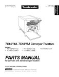
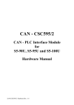
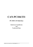
TCO2114 P/N 43336 Rev. B V1 5/00 Domestic, Std. Export & European Export Models: TCO21140063 (USA & std. export, 208V) TCO21140066 (USA & std. export, 240V) TCO21140035 (European export, 230V) TCO21140077 (European export, 380-400V) Conveyor Oven Combinations: Single Oven Double Oven (Two-Stack) Triple Oven (Three-Stack) OWNER'S OPERATING & INSTALLATION MANUAL © 2000 CTX, A Middleby Company is a registered trademark of Middleby Marshall, Inc. All rights reserved. Middleby Cooking Systems Group 1400 Toastmaster Drive Elgin, IL 60120 (847)741-3300 FAX (847)741-4406 página 37 TM ESPAÑOL page 25 FRANÇAIS seite 13 DEUTSCH page 1 ENGLISH ENGLISH/German French/Spanish TABLE OF CONTENTS WARNING: IN CASE OF FIRE Disconnect the oven from its power source IMMEDIATELY. Shutting down the electrical heating elements allows the unit to cool, making it easier to put out the fire. SECTION 1 DESCRIPTION .............................................. 3 ENGLISH WARNING: FOR YOUR SAFETY DO NOT STORE OR USE GASOLINE OR OTHER FLAMMABLE VAPORS OR LIQUIDS IN THE VICINITY OF THIS OR ANY OTHER APPLIANCE A. Features .......................................................... 3 WARNING IMPROPER INSTALLATION, ADJUSTMENT, ALTERATION, SERVICE OR MAINTENANCE CAN CAUSE PROPERTY DAMAGE, INJURY OR DEATH. READ THE INSTALLATION AND OPERATING INSTRUCTIONS THOROUGHLY BEFORE INSTALLING OR SERVICING THIS EQUIPMENT. SECTION 2 INSTALLATION ............................................ 4 B. Component Location and Function .................. 3 C. Electrical Specifications .................................. 3 A. Installation Options and Kit Availability ........... 4 B. Assembly ......................................................... 4 C. Electrical Connection ...................................... 4 SECTION 3 OPERATION ................................................. 5 WARNING DISCONNECT THE OVEN FROM ITS ELECTRICAL POWER SUPPLY BEFORE CLEANING OR SERVICING. A. Location and Function of Controls ................... 5 B. Daily Startup Procedure .................................. 5 CAUTION Using any parts other than genuine CTX factory parts relieves the manufacturer of all liability. C. Operation ......................................................... 6 D. Shutdown Procedure ....................................... 6 IMPORTANT Contact your authorized service agent to perform maintenance and repairs. A service agency directory is supplied with your oven. E. Programming Preset Menu Selections ............ 7 IMPORTANT CTX (manufacturer) reserves the right to change specifications and product design without notice. Such revisions do not entitle the buyer to corresponding changes, improvements, additions or replacements for previously purchased equipment. H. Daily Cleaning ................................................. 9 F. Cooking Time and Temperature Guidelines .... 8 G. Draft Curtain Adjustment ................................. 8 I. Display Messages and Error Codes .............. 10 SECTION 4 ELECTRICAL WIRING DIAGRAMS ............ 11 A. Wiring Diagram and Schematic: TCO21140063 (USA & Std. Export, 208V) and TCO21140066 (USA & Std. Export, 240V) ............................................................. 11 RETAIN THIS MANUAL FOR FUTURE REFERENCE This manual provides detailed information for the installation and operation of your conveyor oven. It also contains information to assist the operator in diagnosing problems in the event of a malfunction. This manual is an important tool for the operator and should be kept readily available. B. Wiring Diagram and Schematic: TCO21140035 (European Export, 230V) ...... 11 C. Wiring Diagram and Schematic: TCO21140077 (European Export, 380-400V) ...................................................... 12 © 2000 CTX, A Middleby Company is a registered trademark of CTX, A Middleby Company. All rights reserved. CTX 1400 Toastmaster Drive Elgin, IL 60120 USA (847)741-3300 Middleby Corp 24-Hour Service Hotline 1-800-238-8444 www.middleby.com 2 FAX (847)741-4406 A. FEATURES B. COMPONENT LOCATION AND FUNCTION The Model TCO2114 Mighty Chef Conveyor Oven is designed to quickly and easily cook, bake, and broil a variety of food products with consistent quality and results. The oven is ideal for preparing pizza, garlic toast, cookies, sandwiches, and other food products. Refer to Fig. 1 for the locations of these components. 1-3.Oven controls - see Section 3, Operation. 4. Crumb trays (3 total) - Collect crumbs that pass through the conveyor. One center crumb tray is located underneath the center of the conveyor. One end crumb tray is located underneath EACH end of the conveyor. Features of the Mighty Chef include: An electronic, programmable controller that allows up to 5 preset menu selections A cool exterior for increased safety A 14 (356mm)-wide conveyor belt that can be easily set to operate in either direction Adjustable draft curtains that reduce draft into the oven and prevent heat loss into the environment Welded and reinforced stainless steel construction Fast countertop installation - no additional components required 5. Conveyor end trays - Provide additional loading/exit space at the ends of the conveyor. 6. Conveyor - Transports the product through the oven, and between the top and bottom heating elements. 7. Adjustable draft curtains (2 total) - Reduce draft into the oven and prevent heat loss into the environment. 8. Fan - Cools the interior components of the oven. Figure 1 - Component location 7. Adjustable draft curtains (2) 6. Conveyor 1. Power On/Off (I/O) switch 2. Conveyor reversing switch 8. Fan 5. Conveyor end trays (2) 3. MenuSelect® keypad and display 4. Crumb trays (3) C. ELECTRICAL SPECIFICATIONS Operating Voltage Frequency Phase kW Rating Current Draw TCO21140063 TCO21140066 TCO21140035 TCO21140077 208V 240V 230V 380-400V 50/60 Hz 50/60 Hz 50 Hz 50 Hz 1 Ph 1 Ph 1 Ph 3 Ph 5.0kW 5.3kW 5.0kW 5.0kW 24.0A (total) 22.1A (total) 21.1A (total) L1 N/A N/A N/A 0.3A L2 N/A N/A N/A 10.5A L3 N/A N/A N/A 10.3A N Cord/Plug Information N/A N/A N/A 10.3A Attached cord with NEMA 6-30P plug Attached cord with NEMA 6-30P plug Kabelmetal-type HO7RN-F cord with 3 x 4.0mm conductors and moulded-on IEC 309 plug Plug is rated 230VAC, 32A N/A 3 ENGLISH SECTION 1 - DESCRIPTION SECTION 2 - INSTALLATION ENGLISH IMPORTANT IT IS THE CUSTOMERS RESPONSIBILITY TO REPORT ANY CONCEALED OR NON-CONCEALED DAMAGE TO THE FREIGHT COMPANY. A. INSTALLATION OPTIONS & KIT AVAILABILITY If the installation will require two or three ovens to be stacked, you must use the separately-available Stacking Kit (P/N T2114STACK). One Kit is required for a two-stack, while two kits are required for a three-stack. Stacking more than three ovens is not permitted. 1. B. ASSEMBLY Installing the Legs a. Carefully tilt the oven onto its rear side. The front (controller) side should be facing directly upwards. b. Thread the four legs into the holes provided on the bottom of the oven. Tighten them until they are secure. 2. Installing the Conveyor End Trays a. Press one of the conveyor end trays down over the end plate of the conveyor frame, as shown in Figure 2. b. Fasten the end tray in place with one of the supplied 8-32x3/8 screws, as shown in Figure 2. c. Repeat the above steps to install the second end tray at the opposite end of the conveyor frame. WARNING ENSURE THAT ANY PACKING MATERIAL RESIDUE HAS BEEN REMOVED FROM INSIDE THE OVENS COOKING CHAMBER. 2. Single-phase Mighty Chef ovens only: Check that the appropriate receptacle is available for the power cord plug. Insert the power cord plug into its receptacle. 3. Three-phase Mighty Chef ovens only: Remove the two screws that hold the rear cover panel in place; then, remove the cover panel. Insert the end of the electrical supply through the connector shown in Figure 3. Attach the electrical supply wires to their terminal block connections, as shown in Figure 3. Secure the supply wires to the floor of the electrical compartment using the supplied cable clamp. The wires must not interfere with the drive chain and sprocket. See Figure 3. Secure the supply as it passes through the connector on the outside wall of the oven. Replace the rear wall of the oven and fasten it in place. 4. If required by national or local codes, connect an equipotential ground wire to the lug shown in Figure 3. The equipotential ground connection must meet all applicable national and local code requirements. CAUTION THE SUPPLIED LEGS AND THE END TRAYS MUST BE FASTENED IN PLACE BEFORE OPERATING THE OVEN. Figure 2 - End Tray Installation 1 2 Position tray Before proceeding with the electrical connection, check that the electrical supply matches the ovens requirements. Refer to the serial plate and to the Electrical Specifications table (in Section 1 of this Manual). WARNING ENSURE THAT BOTH THE CIRCUIT BREAKER/ FUSED DISCONNECT AND THE POWER ON/OFF (I/ O) SWITCH ARE IN THE O (OFF) POSITION BEFORE PROCEEDING. Wherever the Stacking Kits instructions are different from those listed below, follow the instructions provided with the Kit. 1. The toasters power cord and plug provide an electrical ground connection. A separate equipotential ground connection must also be made if required by national or local codes. Consult all applicable national and local codes for further electrical connection requirements. Fasten in place with screw Figure 3 - Electrical Connections 3 Wiring connections Repeat for second tray Terminal block C. ELECTRICAL CONNECTION IMPORTANT Wiring diagrams for the oven are provided on pages 9-10 of this Manual. The electrical connection to the oven requires a circuit breaker/fused disconnect. Consult applicable national and local code requirements to determine the rating of the breaker/disconnect. Electrical specifications are listed on the ovens serial plate and in the Electrical Specifications table (in Section 1 of this Manual). (3-phase ovens only) Equipotential ground lug and symbol (European ovens) 4 Connector (3-phase ovens only) Cable clamp SECTION 3 - OPERATION AND FUNCTION OF j. k. The Up Arrow and Down Arrow keys are used to edit cook time and temperature settings. The Preset Menu keys (1-5) are used to select a Preset Menu to change or operate. This section provides a basic description of the Mighty Chef ovens controls, their location, and the functions they perform. The operator MUST be familiar with the controls. See Figure 4. 2. Power On/Off (I/O) switch Switches the oven ON (I) and OFF (O). 1. MenuSelect® controller Multi-function keypad which contains the following: 3. Conveyor reversing switch Changes the direction of conveyor travel. a. The display shows the current preset menu selection, temperatures, cook time, or error/ service information, depending on the mode of operation. CAUTION Do not operate the conveyor reversing switch while the conveyor is in motion. B. DAILY STARTUP PROCEDURE b. The ready light illuminates when both heating zones of the oven have reached their set temperatures. c. 1. Adjust the position of the draft curtains at the ends of the cooking chamber (if necessary). This procedure is described in detail in Part G, Draft Curtain Adjustment, in this Section. The Top Temp key displays/sets the top zone temperature. d. The Bottom Temp key displays/sets the bottom zone temperature. IMPORTANT When cooking at very high temperatures (either heating zone is 400°F / 204°C or higher), the oven should be pre-heated for at least 10 minutes WITH THE DRAFT CURTAINS IN THE FULLY-LOWERED POSITION and both heating zones set to 599°F / 315°C. After pre-heating, the curtains may be repositioned as required. e. The Cook Time key displays/sets the cook time. f. The Ref Temp key displays a reference temperature for the top or bottom heating zone. g. The Sngl Pizza key adjusts the temperature of the top heating zone to properly cook a single pizza, or the last of a group of pizzas. h. The Prog key allows reprogramming of the five Preset Menu Selections. 2. Restore power to the oven at the circuit breaker/fused disconnect. i. 3. Switch the Power On/Off (I/O) Switch to the ON (I) position. The Prog Override key allows a Preset Menu Program to be temporarily changed. Figure 4 - Controls 1. MenuSelect® controller a b 2. Power On/Off (I/O) switch c g d h e j f i 3. Conveyor reversing switch 5 k ENGLISH A. LOCATION CONTROLS C. OPERATION ENGLISH 1. TO PROGRAM A NEW PRESET MENU SELECTION: Perform the procedure in Part E, Programming Preset Menu Selections, in this Section. At least one menu selection MUST be programmed before the oven can be operated. 2. TO TEMPORARILY OVERRIDE A PRESET MENU SELECTION: Perform the procedure in Part E, Programming Preset Menu Selections, BUT press instead (in Steps 3 and 8). Instead of permanently overwriting the menu selection, the new set of temperature and cook time settings are only temporary. To cancel the temporary menu selection, press any preset menu key or disconnect electrical power to the oven. 3. TO CHOOSE A PRESET MENU SELECTION: a. (or any other preset menu key). The display will read Press . The number in the display (1 is shown above) will match the menu key that was pressed (1-5). b. Wait for the light to illuminate. The light will illuminate after both heating zones reach their set temperatures. 4. TO COOK A SINGLE PIZZA, OR THE LAST OF A GROUP OF PIZZAS: c. Load the product onto the conveyor. a. Choose a preset menu selection, and wait for the b. Press . and light to illuminate. will alternate in the display. The number in the display (1 is shown above) will match the current menu selection (1-5). c. Load the pizza product onto the conveyor. IMPORTANT After 1/2 of the cook time has elapsed, the temperature of the top zone will be automatically lowered. After the entire cook time has elapsed, the program will return to its normal top zone temperature. After 5. TO VIEW THE SET TEMPERATURES: 6. TO VIEW HEATING ZONE REFERENCE TEMPERATURES: 7. TO VIEW THE COOK TIME: is pressed, the menu selection cannot be changed until the cook time has elapsed. or Press either Press + or . The top or bottom set temperature will be displayed for 5 seconds. + . The top or bottom reference temperature will be displayed for 5 seconds. Press . The cook time will be displayed for 5 seconds. D. SHUTDOWN PROCEDURE 1. Switch the Power On/Off (I/O) switch to the OFF (O) position. 2. Wait for the ovens cooling fan to turn off. 3. Disconnect electrical power to the oven at the circuit breaker/fused disconnect. 6 E. PROGRAMMING PRESET MENU SELECTIONS IMPORTANT Adding a menu program to the oven will overwrite an existing program. DO NOT enter a new menu program over an existing program that you wish to keep! ENGLISH 1. Restore power to the oven at the circuit breaker/fused disconnect. 2. Switch the Power On/Off (I/O) Switch to the ON (I) position. 3. Press and hold until 4. CHOOSE A MENU SELECTION TO PROGRAM appears in the display. Press and hold (or any other preset menu key) until appears in the display and begins to flash. The number in the display (1 is shown above) will match the menu key that was pressed (1-5). 5. SET TOP TEMPERATURE a. Press . The current top set temperature appears in the display. b. Press and Pressing as necessary to change the displayed temperature. once increases the active (flashing) digit by one. This digit rolls over to its minimum value if Pressing is pressed when the digit shows its maximum value. once causes the next digit to the right to become the active (flashing) digit. If the far-right digit is flashing when is pressed, the far-left digit will flash and become the active digit. IMPORTANT The allowed temperature range is 200-599°F (93-315°C). If you program a set temperature between 0°F (or 0°C) and 99°F (37°C), the heater will be set to OFF. If you program a set temperature between 100°F (38°C) and 199°F (92°C), the temperature will automatically change to 200°F (93°C), the display will flash, and a beep will sound to alert you to the temperature change. 6. SET BOTTOM TEMPERATURE a. Press . The current bottom set temperature appears in the display. b. Press and as necessary to change the displayed temperature. IMPORTANT Unless you are following specific time and temperature instructions, the top and bottom zone temperatures should be set WITHIN 50°F (28°C) of each other. Greater temperature differences may cause the hotter zone to heat the cooler zone. This can cause inconsistent cooking results. 7. SET COOK TIME a. Press . The current cook time appears in the display (minutes : seconds). b. Press and as necessary to change the displayed time. IMPORTANT The allowed cook time range is 00:30-15:00. If you program a cook time outside of this range, the time will change to the closest allowed time (00:30 if your time was too short, or 15:00 if it was too long). The display will flash, and a beep will sound to alert you to the changed cook time. 8. Press ONE of the following keys: , : Turn off Programming Mode. This returns the oven to normal operation. , or Any other key except : Re-enter the top setpoint temperature, bottom set point temperature, or cook time. or : Resume operation, but leave Programming Mode active. Other Preset Menu Selections can be programmed at this time. 7 F. COOKING TIME AND TEMPERATURE GUIDELINES G. DRAFT CURTAIN ADJUSTMENT The draft curtains may need to be repositioned to provide adequate clearance for some food products. The curtains should be positioned to prevent drafts into the oven, and heat loss into the environment. IMPORTANT ENGLISH The cooking times and temperatures shown below are recommendations only. You should always test each food product to determine correct time and temperature settings. PRODUCT SET TEMPERATURE upper lower The draft curtains can be removed from the oven to permit the maximum vertical clearance above the conveyor. COOK TIME Bagel Bites 400°F/204°C 420°F/216°C 5:00 Biscuits 250°F/121°C 335°F/168°C 6:45 Bread Sticks (retherm) 425°F/218°C 475°F/246°C 4:30 Cheese Sticks (frozen) 460°F/238°C 445°F/229°C 6:00 Chicken Nuggets (frozen) 460°F/238°C 445°F/229°C 6:00 Cookies 375°F/191°C 375°F/191°C 9:00 Garlic Bread (retherm) 425°F/218°C 475°F/246°C 2:30 Hamburgers (frozen) 540°F/282°C 540°F/282°C 5:00 Jalapeno Poppers 460°F/238°C 400°F/204°C 6:45 Pizza (fresh), 12 (300mm) dia. 375°F/191°C 480°F/249°C 6:30 Pizza (retherm), slice 425°F/218°C 500°F/260°C 2:15 Pizza (frozen - slacked in refrigerator 12 hrs. before cooking), 6-8(150-200mm) dia. 380°F/193°C 430°F/221°C 6:30 Pizza, par baked crust 470°F/243°C 525°F/274°C 6:30 Pretzels (pre-cooked) 505°F/263°C 540°F/282°C 0:45 Sandwiches, open-faced 550°F/288°C 550°F/288°C 0:50 WARNING BEFORE ADJUSTING THE DRAFT CURTAINS, SWITCH THE POWER ON/OFF (I/O) SWITCH TO THE OFF (O) POSITION. CAUTION - HOT WHEN REPOSITIONING THE CURTAINS: WEAR A HEAVY OVEN MITT. DO NOT REACH INTO THE OVENS COOKING CHAMBER! See Figure 5. 1. To reposition the draft curtains: a. Loosen the two screws that hold the draft curtain in place. See Figure 5. b. Slide the curtain to the desired clearance above the conveyor. c. Tighten the two screws to hold the curtain in place. d. Repeat these steps for the curtain at the opposite end of the oven. 2. To remove the curtains from the oven: a. Remove the two screws that hold the draft curtain in place. b. Remove the draft curtain. c. Repeat these steps for the curtain at the opposite end of the oven. Figure 5 Repositioning the draft curtains DO keep hands outside of cooking chamber DO NOT reach inside cooking chamber 1 2 Loosen screws Reposition curtain 3 8 Tighten screws H. DAILY CLEANING WARNING WHEN CLEANING THE OVEN: NEVER USE PRESSURIZED WATER. NEVER USE A CLEANING SOLUTION OTHER THAN SOAP AND WATER ON PORTIONS OF THE OVEN THAT COME INTO CONTACT WITH FOOD PRODUCTS. THESE AREAS INCLUDE THE CONVEYOR BELT AND END TRAYS. 6. Clean the end trays USING SOAP AND WATER ONLY and towel them dry. If necessary, the end trays can be removed for cleaning by removing the screws that hold them in place. See Figure 2 (in the Installation section of this Manual). IMPORTANT If the end trays are removed for cleaning, they must be replaced prior to operating the oven. NEVER APPLY ENOUGH LIQUID TO STAND IN PLACE ON THE OVEN. LIQUID INSIDE THE OVEN WILL CAUSE A SEVERE ELECTRICAL HAZARD AND MAY OTHERWISE DAMAGE THE OVEN. 7. Slide the end crumb trays out from underneath the entrance and exit ends of the conveyor. See Figure 6. 8. Lift BOTH ends of the center crumb tray; then, slide the tray out of either end of the oven. CAUTION DO NOT clean your oven using abrasive cleaners or pads. Both will scratch and dull the finish. 9. Clean all three of the crumb trays using a commercial oven cleaner. If necessary, towel them dry. 1. With the conveyor running, use a brush to clean any crumbs off the conveyor into the crumb trays. 10. Replace the center crumb tray in the oven as shown in Figure 7. 2. Switch the Power On/Off (I/O) switch to the OFF (O) position, and wait for the cooling fan to turn off. IMPORTANT Proper positioning of the center crumb tray is REQUIRED for proper cooking. Ensure that the tray is replaced inside the conveyor frame, as shown in Figure 7, and NOT on the floor of the cooking chamber! 3. Disconnect electrical power to the oven at the circuit breaker/fused disconnect. 4. Allow the oven to cool. 11. Replace the two end crumb trays. CAUTION - HOT DO NOT TOUCH HOT SURFACES ON THE OVEN, OR REACH INTO THE COOKING CHAMBER, UNTIL THE UNIT HAS COOLED THOROUGHLY. 12. Clean the outside of the oven using a damp cloth with EITHER soap and water OR a stainless steel cleaner. Use caution to ensure that liquids do not enter the oven during cleaning, especially when wiping the fan grill. Figure 6 End crumb trays and fan grill Figure 7 Center crumb tray placement Clean fan grill using stiff nylon brush Conveyor belt Support tab Slide trays straight out (trays are underneath both ends of conveyor) 9 Tray fits BETWEEN conveyor belt and support tab. DO NOT insert tray on floor of oven! ENGLISH 5. Thoroughly clean the fan grill on the front of the oven using a stiff nylon brush. See Figure 6. I. DISPLAY MESSAGES AND ERROR CODES ENGLISH DISPLAY SHOWS PROBLEM ACTION Flashing temperatures or cook times during programming, and oven is beeping Set Temperatures or Cook Time Outside of Allowed Range Re-enter the program using Set Temperatures and Cook Time within the allowed range. Also, refer to Part E, Programming Preset Menu Selections, in this Section. OFF Heating Element turned off If the element should be on, re-enter the program using Set Temperatures within the allowed range. Also, refer to Part E, Programming Preset Menu Selections, in this Section. ---- No Menu Selection Chosen Choose or program a preset menu selection. E-00 E-01 Preset Menu Program Lost Re-enter the Preset Menu program. High Ambient Condition Temperature inside the control enclosure exceeds 65°C. The oven shuts down, then beeps continuously. Check the cooling fan (centered on the front panel of the oven) for cleanliness and proper operation. If the fan is not running after the oven heats, or the oven remains in a high ambient condition, contact your local Authorized Service Agent. Conveyor Runaway The conveyor runs at full speed. The oven shuts down, then beeps continuously. Check for the proper speed setting by pressing Conveyor Loose or Jammed Conveyor is stopped when the speed setting is between 0:15 and 15:00. Switch the Power On/Off (I/O) Switch to the OFF (O) position. Switch the breaker/fused disconnect to the OFF position. Allow the oven to cool for at least 30 minutes. E-02 E-04 . If the speed setting is correct, and the conveyor continues to run at full speed, contact your Authorized Service Agent. CAUTION - HOT DO NOT ATTEMPT TO FREE A JAMMED CONVEYOR BELT WHILE THE COOKING CHAMBER IS WARM. SEVERE INJURY MAY RESULT. If the conveyor is jammed, free the obstruction from the conveyor belt. If the conveyor still will not operate properly after the jam is cleared, OR if the error message appears when the conveyor is NOT jammed, contact your local authorized service agent. E-35 E-36 Top Heating Zone Failure Contact your local authorized service agent. Bottom Heating Zone Failure Contact your local authorized service agent. E-40 Heating Zone Temperature High Limit One or both of the heating zones have reached a temperature greater than 315°C. Contact your local authorized service agent. 10 SECTION 4 - ELECTRICAL WIRING DIAGRAMS Wiring Diagram, TCO21140063 (Domestic & Std. Export 208V) and TCO21140066 (Domestic & Std. Export 240V) ENGLISH L1 N E TOP HEATER CC FUSES (2) 5.0A/600V TC BOTTOM HEATER CONTACTOR MOTOR PICKUP ASSY TSTAT N.C. FUSE 0.25A TC TFRMR 230Vp 12Vs TFRMR 230Vp 115Vs TSTAT VAR VAR FUSE 0.5A N.O. SSR 1 SSR 2 BLACK WHITE FAN RED POWER ON/OFF (I/O) SWITCH CONVEYOR REVERSING SWITCH MENUSELECT® CONTROLLER Wiring Diagram, TCO21140035 (European Export 230V) Remainder of wiring matches TCO21140063/0066 Electrical Schematic, TCO21140063 (Domestic & Std. Export 208V) and TCO21140066 (Domestic & Std. Export 240V) N L1 TSTAT N.O. CC FUSES (2) 5.0A/600V FAN TSTAT N.C. POWER ON/OFF (I/O) SWITCH 2 POLE C1 C CC FUSE 5.0A/600V 230Vp 115Vs RFI FILTER 230Vp 12Vs CC FUSE 5.0A/600V Electrical Schematic, TCO21140035 0.5A MENUSELECT® CONTROLLER CONVEYOR REVERSING SWITCH SSR 1 (European Export 230V) Remainder of wiring matches TCO21140063/0066 SSR 2 0.25A C2 E M TOP HEATER 2500W SSR 2 230Vp 115Vs SSR 1 BOTTOM HEATER 2500W RFI FILTER 11 230Vp 12Vs 0.5A Wiring Diagram, TCO21140077 (European Export 380-400V) N L1 L2 L3 E TOP HEATER page 1 ENGLISH CC FUSES (2) 5.0A/600V CONTACTOR LINE FILTER TC BOTTOM HEATER TSTAT FUSE 0.25A TC TFRMR 230Vp 12Vs TFRMR 230Vp 115Vs MOTOR PICKUP ASSY RFI FILTER VAR VAR N.C. FUSE 0.5A DEUTSCH TSTAT SSR 1 N.O. SSR 2 seite 13 BLACK WHITE FAN RED POWER ON/OFF (I/O) SWITCH FRANÇAIS MENUSELECT® CONTROLLER page 25 CONVEYOR REVERSING SWITCH Electrical Schematic, TCO21140077 (European Export 380-400V) TSTAT N.O. L2 L3 E FAN POWER ON/OFF (I/O) SWITCH 2 POLE página 37 ESPAÑOL TSTAT N.C. C1 L1 LINE FILTER N C2 C RFI FILTER CC FUSE 5.0A/600V C3 C4 CC FUSE 5.0A/600V 230Vp 115Vs 230Vp 12Vs 0.5A MENUSELECT® CONTROLLER CONVEYOR REVERSING SWITCH SSR 2 0.25A SSR 1 M TOP HEATER 2500W SSR 2 SSR 1 BOTTOM HEATER 2500W is a registered trademark of CTX, A Middleby Company. All rights reserved. CTX 1400 Toastmaster Drive Elgin, IL 60120 USA (847)741-3300 Middleby Corp 24-Hour Service Hotline 1-800-238-8444 www.middleby.com FAX (847)741-4406