1
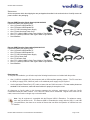
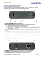
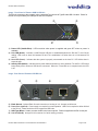
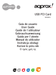
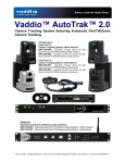
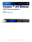
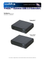
Installation and User Guide Vaddio™ Extreme USB 2.0 Extenders Part Numbers: 999-1005-022 - North America 999-1005-122 - International Extreme USB 2.0 Extender TX Extreme USB 2.0 Extender RX © 2013 Vaddio - All Rights Reserved. Extreme USB 2.0 Extenders, Document Number 342-0468 Rev D Extreme USB 2.0 Extenders Table of Contents Overview .................................................................................................................................................................... 3 Intended Use: ......................................................................................................................................................... 3 Important Safeguards: ........................................................................................................................................... 3 Save These Instructions: ....................................................................................................................................... 3 Unpacking .................................................................................................................................................................. 4 Extreme USB Extenders (North America) 999-1005-022 ...................................................................................... 4 Extreme USB Extenders (International) 999-1005-122 ......................................................................................... 4 Requirements: ........................................................................................................................................................ 4 Anatomy of the Extreme USB 2.0 Extenders ............................................................................................................ 5 Image: Front Panel Extreme USB 2.0 TX Unit .................................................................................................. 5 Image: Rear Panel Extreme USB 2.0 TX ........................................................................................................... 5 Image: Front Panel of Extreme USB 2.0 RX Unit ............................................................................................. 6 Image: Rear Panel of Extreme USB RX Unit .................................................................................................... 6 Installation Instructions .............................................................................................................................................. 7 Checking out the Installation: ................................................................................................................................. 7 Diagram: Basic Connectivity of the Extreme USB 2.0 Extenders ..................................................................... 8 Troubleshooting ......................................................................................................................................................... 9 Specifications:.......................................................................................................................................................... 12 Compliance and CE Declaration of Conformity: ...................................................................................................... 13 Warranty Information ............................................................................................................................................... 14 Extreme USB 2.0 Extenders - Document Number 342-0468 Rev D Page 2 of 16 Extreme USB 2.0 Extenders OVERVIEW The Vaddio Extreme USB 2.0 Extenders provide a complete working solution powered by Extreme USB Long Reach USB 2.0 enabled by the Lion’sGate™ USB 2.0 Extension ASIC. The system has a transmit (TX) or remote device side and a receive (RX) or Host PC side and extends USB 2.0 high speed and USB 1.1 devices up to 100m (328.1’) over Cat-5e or better cable. Extreme USB 2.0 Extenders - RX (left) and TX (right) The TX side has the USB Type-A female USB 2.0 port and is located with the device and powered with the 5 VDC power supply while the RX side is port powered by the Host PC. Power is not required on the RX Host side for normal operation. The Extenders operate with USB 2.0 high-speed host controllers and USB 1.1 classic hosts. All USB device types are supported including Control, Interrupt, Bulk and Isochronous at up to 480Mbp/s. The Extenders are true plug and play and ready to operate out of the box and no new driver installation is required (bonus). The Extreme USB 2.0 Extenders support all major operation systems including Windows®, Mac OS® and Linux® and are ideal for a wide variety of fine USB devices like Vaddio HD-USB Camera, AV Bridge, Quick-Connect™ USB and EasyTalk™ Wireless USB Mic System as well as printers, scanners, and game controllers. Intended Use: Before operating the device, please read the entire manual thoroughly. The system was designed, built and tested for use indoors, and with the provided power supply and cabling. The use of a power supply other than the one provided or outdoor operation has not been tested and could damage the device and/or create a potentially unsafe operating condition. Important Safeguards: Read and understand all instructions before using. Do not operate any device if it has been dropped or damaged. In this case, a Vaddio technician must examine the product before operating. To reduce the risk of electric shock, do not immerse in water or other liquids and avoid extremely humid conditions. Do not connect Ethernet or Power over Ethernet (PoE) cables directly to the RJ-45 ports on the device as damage may result. Use only the power supply provided with the system. Use of any unauthorized power supply will void any and all warranties. Please do not use “pass-thru” type RJ-45 connectors. These pass-thru type connectors do not work well for professional installations and can be the cause of intermittent connections which can result in the data and/or control line failing and locking up. For best results please use standard RJ-45 connectors and test all cables for proper pin-outs prior to use. Save These Instructions: The information contained in this manual will help you install and operate your product. If these instructions are misplaced, Vaddio keeps copies of Specifications, Installation and User Guides and most pertinent product drawings for the Vaddio product line on the Vaddio website. These documents can be downloaded from www.vaddio.com free of charge. Extreme USB 2.0 Extenders - Document Number 342-0468 Rev D Page 3 of 16 Extreme USB 2.0 Extenders UNPACKING All the components within the shipping box are packaged as described in the sections below. Carefully remove all parts included in the packaging. Extreme USB Extenders (North America) 999-1005-022 Unpack and identify the following parts One (1) Extreme USB Extender TX One (1) Extreme USB Extender RX One (1) 5 VDC Switching Power Supply One (1) North American Power Cord One (1) 6’ (1.83m) USB 2.0 Cable Type-A Male to Type-B Male One (1) 1’ (305mm) USB 2.0 Cable Type-A Male to Type-B Male Documentation Extreme USB Extenders (International) 999-1005-122 Unpack and identify the following parts One (1) Extreme USB Extender TX One (1) Extreme USB Extender RX One (1) 5 VDC Switching Power Supply One (1) Euro Power Cord One (1) UK Power Cord One (1) 6’ (1.83m) USB 2.0 Cable Type-A Male to Type-B Male One (1) 1’ (305mm) USB 2.0 Cable Type-A Male to Type-B Male Documentation Requirements: To complete the installation, you will also require the following items that are not included with the product: One (1) USB 2.0 compatible PC (host computer) with a USB compliant operating system. The PC must have the ability to supply 5VDC, 500ma of power or an additional power supply may be required. Cat-5e Unshielded Twisted Pair (UTP) cable or better with two RJ45 connectors. For best results please use standard RJ-45 connectors, mark and test all cables for proper pin-outs prior to use. All references to Cat-5e cable in this document represent the minimum requirement of solid core Cat-5e unshielded twisted pair cable or better. Cat -6 and STP cables can be substituted. Regular Cat-5 cable can be used; however the maximum length may not be achievable. Note: Not all equipment is compatible with the Extreme USB 2.0 Extenders. For whatever reason, some stuff just doesn’t work. The Extreme USB 2.0 Extenders do comply with the USB 1.1 and USB 2.0 specifications, but there are a number of factors that can affect the operation of USB devices over distance. Extreme USB 2.0 Extenders - Document Number 342-0468 Rev D Page 4 of 16 Extreme USB 2.0 Extenders ANATOMY OF THE EXTREME USB 2.0 EXTENDERS Image: Front Panel Extreme USB 2.0 TX Unit The TX unit provides USB Type-A port for standard USB devices. The TX unit is powered by an external AC adapter or the Vaddio HD-USB PTZ camera in the WallVIEW HD-USB PRO kit. ➍ ➊ ➋ ➎ ➌ ➏ 1) USB Device Port (USB Type-A): Accepts USB device. 2) Device LED (Green/Orange): Indicates when a USB device is connected to the Device Port. a. Will illuminate solid green when device is plugged in and active. b. Off when device is in suspend mode or TX unit is powered off. c. Orange when the TX unit detects an overcurrent condition and the attached USB device attempts to draw more than the 500mA current. 3) Power LED (Vaddio Blue): LED turns blue when power is supplied and goes OFF when no power is available. 4) Link LED (Green): Indicates a valid Extreme USB link is established between the RX and TX over Cat-5e cabling. LED turns on when link between RX and TX is established. Off when there is no link between RX and TX. 5) Host LED (Green): Indicates that the system is properly enumerated on the host PC. LED blinks when in suspend state. 6) Activity LED (Amber): Indicates activity when data transmission is active between TX and RX. LED blinks intermittently with or without a USB device connected. The LED is off when in suspend mode. Image: Rear Panel Extreme USB 2.0 TX ➐ ➑ ➒ 7) Earth Ground: Optional Earth Ground connection to housing of unit. Accepts an M2 screw. 8) Power Port: Connects to the AC power supply. Required at TX for proper operation. 9) Link Port (RJ-45): Accepts an RJ-45 connector for Cat-5e cabling (or better). Extreme USB 2.0 Extenders - Document Number 342-0468 Rev D Page 5 of 16 Extreme USB 2.0 Extenders Image: Front Panel of Extreme USB 2.0 RX Unit The RX unit connects to the computer using a standard Type-A male to Type-B male USB 2.0 cable. Power for the RX Unit is provided by the USB port on the Host computer. ➋ ➊ ➌ ➍ 1) Power LED (Vaddio Blue): LED turns blue when power is supplied and goes OFF when no power is available. 2) Link LED (Green): Indicates a valid Extreme USB link is established between the RX and TX over Cat-5e cabling. LED turns on when link between RX and TX is established. Off when there is no link between RX and TX. 3) Host LED (Green): Indicates that the system is properly enumerated on the host PC. LED blinks when in suspend state. 4) Activity LED (Amber): Indicates activity when data transmission is active between TX and RX. LED blinks intermittently with or without a USB device connected. When the TX and RX are in suspend mode, the LED is off. Image: Rear Panel of Extreme USB RX Unit ➎ ➏ ➐ ➑ 5) Earth Ground: Optional Earth Ground connection to housing of unit. Accepts an M2 screw. 6) Power Port (optional): Power supply not required in normal operation. USB Port is required to deliver 500mA to the RX unit. Please avoid the use of inexpensive USB hubs. 7) USB Type-B Port: Used to connect the RX to the host computer. Power is supplied to the RX on this port. 8) Link Port (RJ-45): Accepts RJ-45 connector for Cat-5e cabling (or better). Extreme USB 2.0 Extenders - Document Number 342-0468 Rev D Page 6 of 16 Extreme USB 2.0 Extenders INSTALLATION INSTRUCTIONS Step 1: Before installing the Extreme USB 2.0 Extenders: A. Determine where the computer is going to be located. B. Determine the location of the USB device or USB camera. C. To ensure proper operation it is recommended that only Cat-5e or better (Unshielded Twisted Pair - UTP) cabling is used to connect between the RX unit to the TX unit. The cabling must have a straight-through conductor configuration (568B) with no crossovers and must be terminated with 8P8C RJ-45 connectors at both ends. The combined length of any patch cords using stranded conductors must not exceed 33’ (10m). Please make every effort to minimize the use of stranded Cat-5e patch cables between the extenders. Step 2: Place the RX unit near the host computer and install the supplied 6’ (1.83m) USB 2.0 cable between the RX unit and the USB port on the host computer. The USB port must supply 5 VDC, 500mA to the RX unit. If the computer cannot supply the proper power levels to the RX host unit, then another %V power supply must be used. Step 3: Place the TX unit near the USB device in the desired remote location and install the supplied 1’ (305mm) USB 2.0 cable into the TX unit and the USB Device. For the USB signal, please use the USB 2.0 cables only. Step 4: Plug the 5VDC power supply into a suitable electrical outlet and connect the supply to the TX unit. Step 5: Connect the Cat-5e cabling (not included) into the RJ-45 Link port on the TX unit. Step 6: Plug the other end of the Cat-5e cable into the RJ-45 Link port on the RX unit. Checking out the Installation: A. On the RX and TX units, check that the Power, Host, and Link LEDs are on and that the Activity LED is blinking. If the Link LED is permanently off, then the cabling between the RX and TX unit is not installed properly or is defective. B. For Windows users (2000, XP, Vista, Windows 7), open Device Manager to confirm that the “Generic USB Hub” has been installed. C. For Mac OS X users, open the System Profiler to confirm that the “Hub” has installed correctly. In the left hand column under Hardware, select “USB” and inspect the right hand panel. If the system has been installed correctly, you should find it listed as a “Hub” under the USB High-Speed Bus/USB Bus. Operating System Notes: To open System Profiler in OS X: Open the Finder, select Applications, then open the Utilities folder and double click on the System Profiler icon. To open Device Manager in Windows 2000 or XP: Right click “My Computer” then select: Properties >> Hardware tab >> Device Manager. To open Device Manager in Windows Vista or Windows 7: Open the Start menu, right click on “Computer” then select: Manage >> Device Manager. Extreme USB 2.0 Extenders - Document Number 342-0468 Rev D Page 7 of 16 Extreme USB 2.0 Extenders Diagram: Basic Connectivity of the Extreme USB 2.0 Extenders Vaddio HD-USB PTZ Camera with local power for the camera and the Extreme USB 2.0 TX unit are shown. A Cat-5e cable run from the TX extender (remote side) to the RX extender located at the Host PC to extend USB 2.0 video up to 100m (328.1’). Use the supplied 1’ (305mm) USB 2.0 cable at the camera side USB port and the provided 6’ (1.83m) at the PC side USB host port. Cat-5e patch cords are typically use stranded pairs and can stop working on the High Speed USB 2.0 Signal at over 10’ (3.04m). Local Power 5 VDC 12 VDC USB 2.0 over Cat-5e Cable (solid core) Up to 100m (328.1’) (Not supplied) Extreme USB 2.0 TX Unit (Remote) Supplied 1’ (305mm) USB 2.0 Cable to the USB 2.0 port on the camera Vaddio ClearVIEW™ HD-USB PTZ Camera or other USB 2.0 Device Extreme USB 2.0 RX Unit (Host) Supplied 6’ (1.83m) USB 2.0 Cable Large Format Flat Screen Monitor USB 2.0 Video using UVC Drivers 5VDC, 500ma supplied by PC over USB 2.0 port HD Video Host PC with UC Soft Client Software Simulated Video Images of TCF “The Bank” Stadium (MPLS, MN) Extreme USB 2.0 Extenders - Document Number 342-0468 Rev D Page 8 of 16 Extreme USB 2.0 Extenders TROUBLESHOOTING The following table provides troubleshooting tips. The topics are arranged in the order in which they should be executed in most situations. If you are unable to resolve the problem after following these instructions, please contact technical support for further assistance. Problem Probable Cause All LEDs on the RX unit (PC-Host side) are off. The RX unit is not receiving enough power from the USB port. Solution Possibilities 1) Ensure the USB connection between the RX unit and the host PC is properly installed. Remember to use a USB 2.0 rated cable with USB 2.0 signals. 2) Move the USB connector to another USB port on the host PC. Some PCs have internal hubs and adequate power may not be available on every port. All LEDs on the TX unit (device side) are off. The TX unit is not receiving power for the AC Adapter. 1) Ensure that the AC power adapter is properly connected to the TX unit. 2) Check the viability of the AC electrical outlet. Check that the TX unit’s power LED comes on when plugged into a working outlet. Link LEDs on the TX and RX units are off. The is no connection between the TX and RX units 1) Check the Cat-5e connection and the cable. Avoid using the pull-through or EZ type RJ-45 connectors. Check the pinouts and use 568B straight through standard. 2) Connect a short and known good patch cable between the TX and RX units. If it works, then there is a Cat-5 cabling problem. Link LED on RX unit is on but the Host LED on RX unit is off. The host computer is not powered on. The LEX unit is not connected to the computer (when used with the optional LEX AC adapter). The computer does not support USB hubs. The USB Ranger® 2201 is malfunctioning. Extreme USB 2.0 Extenders - Document Number 342-0468 Rev D 1) Disconnect all USB devices from the TX unit. 2) Disconnect the RX unit from the computer. 3) Disconnect the TX unit from the AC power adapter. 4) Reconnect the RX unit to the computer. 5) Reconnect the TX unit to the AC power adapter. 6) In the Universal Serial Bus controllers section of Device Manager, check that the RX unit is recognized as a “Generic USB Hub”. Page 9 of 16 Extreme USB 2.0 Extenders Troubleshooting (continued) Problem Probable Cause The Extreme USB Extenders were working, but then the Host LED on the TX and RX units are all of a sudden blinking. Now what? The TX unit is in suspend/standby mode. The PC operating system may have put the Extreme USB 2.0 Extenders into a standby state, or no USB devices are attached to the TX unit. All LEDs on both the RX unit and the TX unit are on, but the USB device does not operate correctly or is detected as an unknown device in the operating system. The USB device may be malfunctioning. 1) Disconnect the Extreme USB 2.0 Extenders from the computer. The computer does not recognize the USB device. 2) Connect the USB device directly to the USB port on the computer. The application software for the device is not operating properly. 3) If the device does not operate properly, consult the user documentation for the device. The Extreme USB 2.0 Extenders are malfunctioning Solution Possibilities 1) Recover/Resume the operating system from standby mode (see the PC’s operating system documentation). 2) Attach a USB device to the system. 4) Update your system BIOS, chipset, or USB Host controller drivers from your System/Mother- board manufacturer’s website. 5) If the device operates properly when directly connected to the computer, connect another device (of a different type) to the USB Ranger® 2201. Connect the USB Ranger® 2201 to the computer. 6) If the second device does not operate, the USB Ranger® 2201 may be malfunctioning. Contact technical support for assistance. 7) If the second device does operate properly, the first device may not be compatible with the USB Ranger® 2201. Extreme USB 2.0 Extenders - Document Number 342-0468 Rev D Page 10 of 16 Extreme USB 2.0 Extenders Troubleshooting (continued) Problem USB device is attached to TX unit’s USB port but TX device LED is off. Probable Cause A USB device must have the appropriate driver installed on the computer operating system. Or must us UVC (universal video class) drivers. Solution Possibilities 1) Install the required USB device driver on the computer operating system prior to attaching the USB device to the TX unit. Please see the USB device manufacturer’s website for details. 2) Consult your USB device documentation and power the USB device with the additional USB device manufacturer supplied power supply (if available). Device LED is orange and units are no longer functioning. Overcurrent condition has occurred because USB device draws more power than can be supplied per USB specification (500mA). Power cycle TX Unit. Host and LINK LEDs on RX / TX units blink intermittently. There is a possibility that the TX and RX units don’t have the same firmware revision. Use a different TX / RX pair that has the same firmware revision. Upgrade the TX /RX firmware, contact technical support for assistance. Extreme USB 2.0 Extenders - Document Number 342-0468 Rev D Page 11 of 16 Extreme USB 2.0 Extenders SPECIFICATIONS: Extreme USB 2.0 Extenders Part Numbers Range USB device support USB host support AC adapter(s) AC adapter connector Current available to USB device at RX unit RX unit USB connector TX unit Link connector TX unit Link connector TX unit USB connector RX unit dimensions TX unit dimensions TX power consumption RX power consumption System shipping weight Operating temperature range Storage temperature range Operating humidity Storage humidity Regulatory testing ESD rating 999-1005-022 North America 999-1005-122 International 100m (330ft) over Cat-5e (or better) cable High-speed devices (480 Mb/s) (USB 2.0) Full speed devices (12 Mb/s) (USB 2.0 & 1.1) Low speed devices (1.5 Mb/s) EHCI (USB 2.0) and OHCI/UHCI (USB 1.1) Input: 100/240 V AC, 50 – 60 Hz, 600 mA maximum Output: 5 VDC, 3 A 1.7 mm center-positive jack 500 mA 1 x USB Type-B 1 x RJ45 1 x RJ45 1 x USB Type-A 3.94” x 2.99” x 1.02” (100 mm x 76 mm x 26 mm) 3.94” x 2.99” x 1.02” (100 mm x 76 mm x 26 mm) 500 mA maximum Approx. 500 mA (No Load). 1.5A (Full load) 2.0 lbs. (0.9 kg) 0°C to 50°C -20°C to 70°C 20% to 80% relative humidity, non-condensing 10% to 90% relative humidity, non-condensing FCC (Class B), IC (Class B), CE (Class B) EMC EN-61000-4-2 8kV Contact, 16kV Air Extreme USB 2.0 Extenders - Document Number 342-0468 Rev D Page 12 of 16 Extreme USB 2.0 Extenders COMPLIANCE AND CE DECLARATION OF CONFORMITY: Extreme USB 2.0 Extenders Compliance testing was performed to the following regulations: FCC Part 15, Subpart B ICES-003 ISSUE 4, 2004 EN55022 A1 2007 IEC 60950-1:2005 (2nd Edition); Am 1:2009 EN 60950-1:2006+A11:2009+A1:2010+A12:2011 Class B Class B Class B Class A Class A FCC Part 15 Compliance This equipment has been tested and found to comply with the limits for a Class A digital device, pursuant to Part 15, Subpart B, of the FCC Rules Operation is subject to the following two conditions: (1) This device may not cause interference, and (2) This device must accept any interference including interference that may cause undesired operation of the device. ICES-003 Compliance ICES-003, Issue 4: 2004 This digital apparatus does not exceed the Class B limits for radio noise emissions from digital apparatus set out in the Radio Interference Regulations of the Canadian Department of Communications. Le présent appareil numérique n’emet pas de bruits radioélectriques dépassant les limites applicables aux appareils numeriques de la classe B préscrites dans le Règlement sur le brouillage radioélectrique édicte par le ministère des Communications du Canada. European Compliance This product has been evaluated for Electromagnetic Compatibility under the EMC Directive for Emissions and Immunity and meets the requirements for a Class A digital device. In a domestic environment this product may cause radio interference in which case the user may be required to take adequate measures. Standard(s) To Which Conformity Is Declared: European Standard EMC EN-55022:2006+A1:2007 Class B EN 61000-3-2:2006 EN 61000-3-3:2003 EN55024:1998 + A2:2003 Extreme USB 2.0 Extenders - Document Number 342-0468 Rev D Page 13 of 16 Extreme USB 2.0 Extenders WARRANTY INFORMATION: (See Vaddio Warranty, Service and Return Policies posted on vaddio.com for complete details): Hardware* Warranty: One year limited warranty on all parts. Vaddio warrants this product against defects in materials and workmanship for a period of one year from the day of purchase from Vaddio. If Vaddio receives notice of such defects during the warranty period, they will, at their option, repair or replace products that prove to be defective. Please see Vaddio’s Service Terms and Conditions at vaddio.com for specific details and policies. Exclusions: The above warranty shall not apply to defects resulting from: improper or inadequate maintenance by the customer, customer applied software or interfacing, unauthorized modifications or misuse, operation outside the normal environmental specifications for the product, use of the incorrect power supply, improper installation (plugging things in wrong), improper extension of the power supply cable or improper site operation and maintenance. Vaddio Customer Service: Vaddio will test, repair, or replace the product or products without charge if the unit is under warranty and is found to be defective. If the product is out of warranty, Vaddio will test then repair the product or products. The cost of parts and labor charge will be estimated by a technician and confirmed by the customer prior to repair. All components must be returned for testing as a complete unit. Vaddio will not accept responsibility for shipment after it has left the premises. Vaddio will only advance replace out of box failures or random equipment failures up to 30 days after the purchase date (not the install date). Vaddio Technical Support: Vaddio technicians will determine and discuss with the customer the criteria for repair costs and/or replacement. Vaddio Technical Support can be contacted through one of the following resources: e-mail support at [email protected] or online at www.vaddio.com. Return Material Authorization (RMA) Number: Before returning a product for repair or replacement, request an RMA from Vaddio’s technical support. Provide a technician with a return phone number, e-mail address, shipping address, and product serial numbers and describe the reason for repairs or returns as well as the date of purchase and proof of purchase. Include your assigned RMA number in all correspondence with Vaddio. Write your assigned RMA number on the clearly on the shipping label when returning the product. All products returned for credit are subject to a restocking charge without exception. Voided Warranty: The warranty does not apply if the original serial number has been removed or if the product has been disassembled or damaged through misuse, accident, modifications, or unauthorized repair. Cutting the power supply cable on the secondary side (low voltage side) to extend the power to the device voids the warranty for that device. Shipping and Handling: Vaddio will not pay for inbound shipping transportation or insurance charges or accept any responsibility for laws and ordinances from inbound transit. Vaddio will pay for outbound shipping, transportation, and insurance charges for all items under warranty but will not assume responsibility for loss and/or damage by the outbound freight carrier. If the return shipment appears damaged, retain the original boxes and packing material for inspection by the carrier. Contact your carrier immediately. Products Not Under Warranty: Payment arrangements are required before outbound shipment for all out of warranty products. *Vaddio manufactures its hardware products from parts and components that are new or equivalent to new in accordance with industry standard practices. Other General Information: Care and Cleaning Do not attempt to take this product apart at any time. There are no user-serviceable components inside. Do not spill liquids in the product Keep this device away from food and liquid For smears or smudges on the product, wipe with a clean, soft cloth Use a lens cleaner on the lens, but this doesn’t have a lens, so don’t Do not use any abrasive chemicals. Operating and Storage Conditions: Do not store or operate the device under the following conditions: Temperatures above 40°C (104°F) or temperatures below 0°C (32°F) High humidity, condensing or wet environments In swimming pools or wading ponds In inclement weather Dry environments with an excess of static discharge Under severe vibration Extreme USB 2.0 Extenders - Document Number 342-0468 Rev D Page 14 of 16 Extreme USB 2.0 Extenders Inside Back Cover - Blank Extreme USB 2.0 Extenders - Document Number 342-0468 Rev D Page 15 of 16 Extreme USB 2.0 Extenders Toll Free: 800-572-2011 ▪ Phone: 763-971-4400 ▪ FAX: 763-971-4464 www.vaddio.com ©2012 Vaddio All Extenders Rights Reserved. Reproduction in wholeRev or inD part without written permission is prohibited. Specifications pricing Extreme USB- 2.0 - Document Number 342-0468 Pageand 16 of 16 are subject to change without notice. Vaddio, Quick-Connect, EasyTalk and ClearVIEW are trademarks of Vaddio. All other trademarks are property of their respective owners. Document 342-0468 Rev. D