1
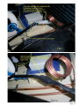
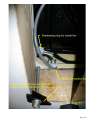
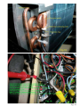
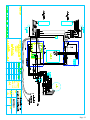
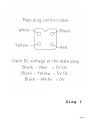
TECHNICAL MANUAL
for IBIS ROOFTOP
AIRCONDITIONER
ERROR CODES &
THEIR MEANING
Aircommand Australia Pty Ltd
954 Port Road
Albert Park
South Australia 5014
Email: [email protected]
Pantone Cool Grey 9U
Pantone 301 U
TECHNICAL MANUAL for IBIS ROOFTOP CARAVAN
AIRCONDITIONER
ERROR CODES & THEIR MEANING:
E1: Room sensor fault. Usually a faulty connection (plug), damaged lead or a faulty sensor
itself.
Action:Check White plug is connected on main board.
Check resistance of thermistor & cable by measuring
with a multimeter. 10K ohm @25C. See fig 19 and table 1.
If open circuit or out of calibration, replace.
E2: Inside coil sensor fault: Usually a faulty connection (2 plugs)
Damaged lead or faulty sensor.
Action:Check Yellow plug is connected on the main board. And also plug in
bundled wiring near the coil.
Check resistance of thermistor & cable by measuring
with a multimeter. 10K ohm @25C. See fig 19 and table 1.
If open circuit or out of calibration, replace.
When replacing this thermistor, install such that cable is downward from
the copper pocket on the coil. See fig 18
E3: Outside coil sensor fault Usually a faulty connection (2 plugs), damaged lead or
faulty sensor.
Action:Check Red plug on main board and extension plug in
bundled wiring usually located near capillary tube coils.
Check resistance of thermistor & cable by measuring
with a multimeter. 10K ohm at 25C. See fig 19 and table 1.
If open circuit or out of calibration, replace.
E4: Indicates lack of refrigerant, or the compressor is not running, or the thermistor is out of
calibration.
Action:
Check that the compressor is running by listening.
If it is apparent that the compressor is running, then check the
temperature difference across the evaporator.
i.e. Measure temperature of return air at inlet filters and
measure temp. of discharge air at grilles. This temp diff.
should be 14 to 18 C. with fan on hi speed. If temp diff. is less than this,
suspect lack of refrigerant.
Fit a suction gauge to access valve at rear of unit. See fig 12. On a 35C
outside temp. then suction should be 380 to 450Kpa.
Page 1
Action (continued)
If the temp. differential is 14C or more but unit goes out on E4 after
approx. 30 minutes, please check the actual
thermistor temperature by the following procedure.
With the inside fan running on Hi.
Press Temp down button followed by the mode button.
Hold them both in for approx 5 seconds. The amber
Lock LED illuminates.
Now press the Temp down button and the Sleep button
Together for about 1 second. The green Med speed will be Flashing. The
display is now reading the temp of the
outside coil. Now press the Temp up button once. The
Green Hi speed will be flashing. The display is now
reading the temp. of the inside coil.
This temp will usually be from 5 to 12 C. If it is above 24C. It is another
indication of lack of refigerant. If on the other hand the air on /air off
differential is 14C or greater then suspect the thermistor itself to be out
of calibration. Check the thermistor as per an E1,E2 or E3 failure by
measuring its resistance. See fig 19 and referring to table 1.
E5 indicates excessive temp. of the outside coil if on cooling, OR excessive temp of the inside coil in
heat mode. On cooling, the E5 will appear if the outside coil temp exceeds 68C. This is an indication
of condenser airflow reduced or non-existent. Using the procedure described above it is possible to
watch the condenser coil temp using the Temp down button and Medium fan speed combination to
display this temp. NB: if fans etc seem to be OK then measure thermistor resistance and refer to table
12. In case the problem is thermistor calibration.
Action:
If unit is in cooling mode, examine both condenser fans are running. If
one is running then suspect a faulty motor. If both fans not running then
on units up to serial No. IBSA 01175, investigate the fan speed control
card located in enclosure on the LHS See fig 6.
If this checks OK then investigate main control card.
Fig 1, 2 or 3. Units with serial No’s IBSA01176 and
onward are multi speed tapped wound motors not requiring a speed
control card. If both motors inoperative then suspect main control card.
Fig 1, 2 or 3.
If unit is in heating mode, examine the indoor fan that it is free to rotate.
If fan is inoperative but free to rotate, then. Units up to S/N IBSA01175,
examine speed control card. See Fig 1. If OK then examine fan motor &
capacitor.
Winding resistance: Blue /Black approx 165 Ω
Blue / Brown approx 480 Ω
If after S/N IBSA01175, check winding resistance
Blue /Black 580Ω
Blue /Grey 630Ω
Blue /White 685Ω
Brown/Yellow 785Ω
If fan motor and capacitor check out OK then
change the main control board.
NB: When in Heat mode, at outside temps above 18C, the outside fan motors may cycle on and off .
This is the system-shedding load to avoid overheating the inside coil and is not a fault.
Error codes E6 & E7 are not utilised in this system. If either of these codes appear, then change the
main control board.
Page 2
When attempting to diagnose a fault over the phone, please ask the following questions. Also it is
usually possible to direct the customer to extract thermistor temp. data as described before. This
can make fault finding more accurate.
1: Is or have there been any error codes displayed?
2: Does the display board appear normal?
Are temperatures displayed from 16 to 30 C?
3: In heating or cooling modes, can the temperatures be altered via the up /down buttons from 16 to
30C?
4: Is the display showing “0”?
5: Is the display showing an unusual figure?
6: When the unit is set to “FAN” only, does the inside fan have 3 speeds?
Does the inside fan blow air?
7: Can the compressor be heard running?
Error codes are an important clue to diagnosing various problems.
Refer to pages 1 & 2 for information on error codes E1 to E7.
However if you have a blank display it may be due to either a faulty 12 volt power supply to the main
board or a broken conductor in the control cable or a displaced plug. See pp: 6 para. 2 & 3.
The control cable has 4 conductors, Black, Red, White & Yellow.
If the Black or White conductors are broken, then there will be no display
If the Yellow or Red conductors are broken, then the display will read “0”
In addition, if one or the other Yellow or Red conductors are broken, then, if the unit is in “Auto
change over” mode, then both the Green cooling LED and the Red heating LED will be flashing
together. This will be conclusive proof of a break in the conductors.
(Auto changeover mode is established by pressing the mode button Cool - Dry - Heat - Fan - Cool.
Either the Green LED is illuminated constantly and the Red LED is flashing. This indicated the unit is
ready to cool. If the Red is constant and the Green is flashing, then the unit is ready to heat.)
If an unusual figure is displayed it may be attributed to an external switch mode power supply (SMPS)
out of adjustment. Fig 4 & 5A shows an external SMPS.
Serial No’s. IBSA 03280 to 034821.Serial no’s IBSA03482 to 03504 were fitted with remote SMPS’s
(see fig 4 & 5A and 20). and IBSA 03505 onwards have the power supply integrated into the main
control board see fig 3.
If the unit is being operated on a generator, a “0” or any other unusual display occurs, this indicates a
problem with the sine wave ouput from the generator.
Assuming the unit is OK on mains power.
Page 3
Typical faults or complaints
1: Any complaint accompanied with an error code, see earlier pages.
2: Unit will not work and no display is evident.
Check the following:
Main ECB breaker is set to ON
Mains power is OK at output from ECB
Is the 4 core control cable plugged into the receiver in the inside plenum? Fig 23
Faulty mains connection at the underside of unit. See Fig 11
A blown fuse on the main control board. See fig 1, 2 & 3.
A blown fuse may be caused by a faulty condenser or evaporator fan
Or a faulty fan speed control card (up to serial No 001176)
Poor connection on main board.
The power supply to the main control board is faulty. This condition can be
diagnosed by checking at the breakaway plug between the control cable and the display in the
plenum. See wiring diag. 1 & 1A. If the DC voltage is not attainable there then suspect a faulty
power supply. See onward:
Earlier models had a transformer. See fig 1. Check output by measuring
for 12V AC at the red plug. See fig 1 & 2. If no output replace transformer with an
SMPS.
If unit is of later manufacture and has an external SMPS (fig 4 shows the SMPS
mounted also fig 20) then measure the output at red plug. Should be 12V DC. If no
output, change the SMPS. Some SMPS have an adjustment pot fig 20. Try adjusting
either direction to see if it regains output.
Units from IBSA 03280 have an integrated SMPS on the main board fig 3.
Except for units IBSA 03482 to 03504 which had external SMPS’s
3: Unit drops out the ECB breaker:
Use a 500V megger to check for ground leakage.
It is possible to unplug both condenser fans and the evaporator fan.
Unplug each until the megger shows at least 10MegΩ or greater to earth.
Likewise the compressor can be disconnected to isolate it from the system.
In this way any faulty components can be identified.
Other places to check: earlier models did not have heatshrink on breakaway plugs on the
condenser fans.
Check also the mains connection on the underside of the unit within the 356mm square ceiling
hole.
4: Compressor will not start:
Check that the control board is outputting to the compressor.(yellow wire
from compressor relay). See fig 1, 2 & 3.
Check start and run capacitors. (LHS enclosure see Fig 6) Note: Not all units are fitted with
start capacitors and relays.
Use a clamp ammeter to check for current to compressor. Continuous current
above 6 Amps indicates a faulty compressor.
Check winding continuity:
If a Sanyo: C-RHN1005A or B
Main Wdg. 2.9 Ω @ 25C
Start Wdg. 6.6Ω @ 25C
If an Aisulu: QHR 19E
Main Wdg 2,2 Ω @ 25C
Start Wdg. 4.2 Ω @ 25C
Page 4
Resistance to earth minimum 20 Meg Ω
5: On cooling mode, compressor and outside fans stop.
Unit ceases to cool but display temp. drops to a low figure. Maybe
less than 10C.
This is typical of an inside coil icing up. The thermistor detects that the coil
is at or below zero and turns off the compressor until temp. rises to 12C,
Whereupon the compressor will restart.
This situation is usually associated with the unit running for a prolonged period
on low fan speed particularly in high humidity conditions.
This problem is usually overcome by running the unit on a higher speed and not
using ‘Auto” fan.
Check also that the return air filters are clean.
In heating mode, the unit stops heating, inside fan stops, and the red heat LED blinks.
This condition indicates that the unit has entered the de-ice mode to rid itself of frost on the
outside coils. The unit will restart automatically in 5 to 10 minutes.
It may be noted that the display temp drops to a low figure.
On resumption of heating, the blinking red light turns to a steady red, and the
inside fan start will be delayed until the inside coil is warmed to 32C. When the inside fan does
start there may be a momentary puff of vapour. This is normal.
7: In very cold conditions the compressor can be heard running but the inside fan does not start.
Be patient, in very cold conditions the unit needs time to warm sufficiently to start producing
warm air.
8: Compressor transmits excessive vibration.
Check that the top washer of the four compressor studs are clear of the rubber
Mount by 1 to 2 mm. Adjust if necessary. See fig 7
9: On heating, the unit cycles regularly, the temperature display indicates say 24 to 28C but the average
temperature in the van is very much less.
Disassemble the facia from the inside plenum (4 screws) and examine carefully
the extension duct for leaks, particularly where it joins the horizontal duct.
A leaking duct will short cycle warm air onto the return air sensor causing the compressor to
close down prematurely.
Repair any leaks and reassemble. (see Fig 10 and 24)
10: On cooling, the unit cycles regularly, the temperature display indicates say 22 to 25C but the
average temperature in the van is very much more.
Disassemble the facia from the inside plenum (4 screws) and examine carefully
the extension duct for leaks, particularly where it joins the horizontal duct.
A leaking duct will short cycle cold air onto the return air sensor causing the
compressor to close down prematurely.
Repair any leaks and reassemble. (see Fig 10 and 24)
11: Water drips from the inside plenum when the unit is in cooling mode.
Ingress of water on cooling mode may be due to either of four conditions.
1: The unit is installed more than 5°out of level, particularly nose down.
2: The drain holes in the evaporator area are blocked. See Fig 8
3: Condensation that has drained onto the roof, has re entered the installation hole either
under the roof seal of the airconditioner or a roof seam near the unit is faulty. If case 3
appears likely, the unit should be reinstalled using a new sealing gasket and following the
Aircommand instructions explicity.
If there is a roof seam involved, clean the seam area thoroughly and reseal
Page 5
with silicone.
Please Note: If water “pools” around the airconditioner (ie. The roof has
sagged around the airconditioner) then the caravan manufacturer should be
consulted.
4: In high humidity areas, condensation may occur on the underside of the evaporator tray
above the inside plenum. See fig 10 and 24.
This usually is associated with running the unit on low speed for a prolonged period. Under
these conditions use the high or medium speeds and avoid “auto”
As it will cause the inside fan to drop to low speed as the set point temperature is
approached.
Later production is fitted with more insulation on the underside to alleviate this problem.
Quote part No 8001056……..
12: Water drips from the inside plenum only when it rains.
Check condition 11 point 3 above.
Water ingress could also be due to rain entering the canopy/chassis
joint and not being able to drain away to the outside. Check the limber holes in the nose
of the chassis. Refer fig 9 and check that the two drain holes are clear in the evaporator area.
13:Unit does not turn on. No display lights on the flip down display.
Proceed to check the following in order.
1: Check circuit breaker is on and the van has power.
2: Unscrew the inside plenum (4 screws) and disconnect plenum from control cable via the
4 pin plug. With a multimeter, check power at inlet junction block. 240V AC. If OK, shift
multimeter to 12V DC range.
Check voltage across the control cable conductors. See Diag 1 & 1A
If the correct voltages are detected as per Diag 1, then suspect a break
between this plug and the display module. Inspect plug pins. Disassemble the display and
check the plug to board is OK. (see fig 23) If the voltages can be detected right up to the
display, replace display.
3: If the voltages cannot be detected at the breakaway plug, then suspect the problem to be in
the main control board enclosure.
Remove the canopy from the unit. Isolate the power to the aircon.
Remove lid of the RHS enclosure to gain access to the control board.
See Fig 1, 2 & 3. Firstly check the fuse on the board. If this fuse is blown it may
indicate a fan motor fault. If the fuse is ruptured, replace with a M205 S/Blow 5A 20 x
5. If the fuse blows again, start investigating for a faulty condenser, evaporator motor or
R/V.
If the fuse is not an issue, and the serial no of the unit is below IBSA02177. Then one
needs to investigate the power supply driving the main board. If the board is powered
from a transformer see fig1, then power up the unit, remove the 2 pin white plug that
connects the transformer to board and with a multimeter set to 12V AC, check output. If
no output, suspect a faulty transformer. Replace with a SMPS Part No 8001039……..
For units below serial no IBSA 03280 and above 02177, these units will be fitted with
an external switch mode power supply. See fig 2.
Here again remove the 2 pin white plug from the SMPS to board, set
multimeter to 12V DC and check output. Earlier SMPS’s had an adjustment pot see fig
20. It is worthwhile adjusting this pot if there is no output.
If the power supply is deemed faulty then replace part No 8001039……
If the power supply is outputting OK, then change the main board.
Units Serial no above IBSA 03280 will have a main control board
with the power supply integrated on it. see fig 3
If there is no voltage output at the control cable with the integrated version, change the
control board.
Page 6
Recharging in the field:
If the unit has the following deficiencies in cooling mode:
Assuming outside temp. is close to 35C and inside 27C
1: The difference in temp. between the inside return air and the
discharge air is less than 14C. (inside fan on Hi )
2: The inside coil temp (as measured with thermistor (see pp 1&2)
is more than 14C
3: The suction pressure (measured at access valve see figs 12) is less than 400 Kpa, then
it is indicative of a lack of refrigerant charge.
Firstly examine the hermetic system for possible leaks. Check both access valves with an
electronic detector.
If any access valves are suspect, then renew the caps with models incorporating a seal. See fig
12d.
Any leak found in solder joints etc. will require the unit to have any remaining refrigerant
recovered, the leak repaired and checked and the unit evacuated and recharged. (720 grams)
A unit that may have had a leak at an access valve and this has been rectified, can have
refrigerant added. Add refrigerant until a good fit is made with the above parameters. I.e. Suction
pressure above 400 Kpa, delta T greater than 14C and the inside coil below 14C.
The use of Independent generators or Inverters:
Failure to start the Aircon:
1: Check that the Generator or Inverter is rated at 2.8 KW or
greater.
2: Check that no other accessories are making a demand on the
power load.
To check on possible hidden loads, directly wire the aircon.
to the genset. If unit starts OK then advise the client to identify and isolate the extra
electrical load.
The display panel has an unusual display of numerals. Unit is however OK
On mains power:
1: This is a sign of a poor waveform being generated.
Advise client to have generator repaired or replaced with
A better quality unit.
Page 7
SPECIFICATIONS
Electrical rating:
Nom. Cooling capacity
Nom. Heating capacity
Max rated current cooling
Max rated current heating
L/R Amps
Inside air delivery
Installed weight
240V 50Hz
3.2KW
3.2KW
5.4Amps
5.6Amps
20Amps
140 l/s
49Kg
Overall height 220mm
Overall width
825mm
Overall length1040mm
Inside plenum height
Inside plenum width
Inside plenum length
Plenum weight
65mm
535mm
555mm.
2.4kg
Refrigerant Charge
720grms R22 or 720grms R407C if marked
Compressor:
Or
Or
Aisulu QHR 19E (early production)
Sanyo C-RH100H5B Pt. No 0018290
Run capacitor 30 µf x 440 VAC4101072
Start capacitor(if used) 64 µf x 330 VAC
8001040
Start relay
Omron AMVL-300A
8001042
PTC relay
GYE101A
Condenser and Evap fan motors (single speed to s/n 001177)
Fan Capacitor 1.5 µf
4402060
Condenser Fan (3 speed s/n 001178 upward)
Fan Capacitor 2 µf
8001052
Evaporator Fan (3 speed s/n 001178 upward)
Fan Capacitor 2 µf
8001051
Main electronic controller (outside unit) up to s/n 001177
Modified for single speed evap fan
Main electronic conroller (outside unit) with inbuilt SMPS
5601050
Speed control card (up to s/n 001178)
4402061
5601056
Inside electronic display5601060
Page 8
Table 1
Thermistor temperature / resistance relationship
Actual temperature °C
Resistance in K Ω
-10
-9
-8
-7
-6
-5
-4
-3
-2
-1
0
1
2
3
4
5
6
7
8
9
10
11
12
13
14
15
16
17
18
19
20
21
22
23
24
25
26
27
28
29
30
31
32
33
34
45
43
41
39
37
36
34
32
31
30
28
27
26
25
24
23
22
21
20
19
18
17.5
17
16
15.5
15
14.3
13.7
13
12.6
12.2
11.7
11.2
10.8
10.4
10
9.6
9.2
8.9
8.6
8.3
8
7.7
7.4
7.1
Page 9
35
36
37
38
39
40
41
42
43
44
45
46
47
48
49
50
51
52
53
54
55
56
57
58
59
60
61
62
63
64
65
66
67
68
6.8
6.6
6.4
6.1
5.9
5.7
5.5
5.3
5.2
5
4.8
4.6
4.5
4.4
4.2
4.1
3.9
3.8
3.7
3.6
3.5
3.3
3.25
3.1
3
2.9
2.8
2.75
2.7
2.6
2.5
2.45
2.4
2.3
Example:
The thermistor sensor is in free air and the free air temp. is measured as 35C.
The resistance of the thermistor assy. is measured at 6.8KΩ
This indicates the thermistor assy is OK
The thermistor assy in free air is 20 C.
The resistance is measured as 6.6KΩ which relates to 36C
This indicates that the thermistor is defective and should be changed.
Page 10
Page 11
Page 12
Page 13
Page 14
Page 15
Page 16
Page 17
Page 18
Page 19
Page 20
Page 21
Page 22
Page 23
Page 24
Page 25
Page 26
Page 27
Page 28
Page 29
Page 30
Page 31
Page 32
Page 33
Page 34
Page 35
Page 36
Diag 1
Page 37
Page 38
INDEX
A:
Access valve
Accumulator
Air registers
Amperage
B:
Buffer
Broken control cable
see figs 4b,12,A,B,C,D
see fig 4b,13,21
see fig 14
see pp. 9 general specifications
see fig 15A & B, fig 21
see pp3
C:
Cable control
Capacitor
Capillary
Chassis
Coil Ice Up
Compressor
Condensate
Connection block
Condenser fan
Condenser coil
Control cable
Controller main
Controller speed
see fig 1, see pp4, see wiring diags
see general speci. pp9, see also figs 4b & 5
see fig 3, 21
see fig 21
see pp5:5
see speci. pp9, see figs 15 a&b, 21
see pp5,6 paragraph 11&12
see figs 22 & 24
see fig 10
see pp2 & 4, see figs 4b, 21
see figs 16 & 21
see wiring diags, see figs 1, 11 & 11a , 14, pp3
see figs 1,2 & 2a
see pp4, see fig 5
D:
De-Icing
Display
Discharge temp.
Drain
Duct extension
Duct horizontal
see pp5
see pp3 figs 22 , 23, pp3
see pp 7
see fig 21
see fig 24
see figs 9, 17
E:
F:
Electrical faults
Enclosures
Electrical data
Error codes
Evaporator
Evaporator tray
Evaporator fan
Extension duct
see speci pp9 for fan motor data. See pp5 for compressor data
see figs 1,2,3,21
see specifications pp9
see pp1,2,3
see Fig 18, 21
see figs 10,18,21
see fig 21
see fig 10 & 24
Fans
Filters
Fin coils
see pp 2,3,4(3),6
see figs 4b,17 21
see pp5 see fig 14
see fig, 16,18,21
G:
Generator operation
see pp 3,7
Grille condenser dischargesee fig 21
Grille plenum discharge see fig 14
Page 39
H:
Hermetic system Hold down bolts
I:
J:
Inside coil
Inverter
see fig 21
see fig 10 & 21
see fig 18, 21
see pp 7
K:
L:
Limber holes
see fig 8
M:
N:
Noise compressor
see pp5 (8) see fig 6
O:
Display
see pp3
P:
Power requirements
Plenum
Plugs
Pressure
see Speci. pp 9
see fig 14
see pp4 see figs 4b , 18, 11, 11a
see speci pp9
Q:
R
Recharging
Refigerant
Roof seal
Return air
Return air sensor
Return air filter
Reversing valve
Rubbers
see pp 7
see speci pp9
see pp 5 (11)
see pp5 (9 ), pp5 (10) see fig 14
see pp 1
see fig 14
see fig 21
see fig 6
S:
Seal roof
see pp 5 (11)
Sensor
see pp 1 & 2 see figs 16,18,19 & Table 1
Specifications
see pp 9
Speed controller (module) see pp 4 & fig 1 & 5
Springs
see fig 6
Schrader valves
see Access valves
Suction pressure
see pp 7
Switch mode power supply
External
see pp 3 &4 see fig 3 & 20
Switch mode power supply
Internal
see fig 25…. See wiring diag
Page 40
T:
Thermistor
see pp1,2
see figs 16,18,19
see table 12
U:
V:
Voltage
W:
Water ingress
Watts in
Wiring Diags.
see speci pp9
see pp6
see speci pp9
see pp 10,11,12
Page 41