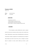
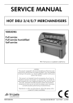
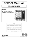
1
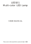
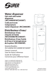
SERVICE MANUAL
TG - ROTISSERIE OVEN MODELS
MODELS
Manual controls
TG50 M
TG110 M
TG330 M
TG550 M
Model TG330 M
- NOTICE This manual is prepared for the use of trained Service Technicians and
should not be used by those not properly qualified. If you have attended
a trianing for this product, you may be qualified to perform all the procedures in this manual.
This manual is not intended to be all encompassing. If you have not
attended a training for this product, you should read, in its entirety, the
repair procedure you wish to performto determine if you have the necessary tools, instruments and skills required to perform the procedure.
Procedures for which you do not have the necessary tools, instruments
and skills should be performed by a trained technician.
Reproduction or other use of this Manual, without the express written
consent of Fri-Jado, is prohibited.
WWW.FRIJADO.COM
Service Manual TG50/110/330/550 form 9123648 rev. 04/2006
EMPTY PAGE
Page 2
Service Manual TG50/110/330/550 form 9123648 rev. 04/2006
Index
Index............................................................................................................................................................3
General technical data.................................................................................................................................4
Technical Data U.S. Standard Models....................................................................................................................................4
Technical Data U.S. Special Models.......................................................................................................................................4
Removal and replacement of parts for the TG50/110/330/550 M................................................................5
Right or left side panel TG330/550.......................................................................................................................................5
Right side Panel TG110........................................................................................................................................................5
Right or left side panel TG50................................................................................................................................................5
Top cover TG330/550..........................................................................................................................................................6
Top cover TG110.................................................................................................................................................................6
Top cover TG50...................................................................................................................................................................6
Left side panel TG110..........................................................................................................................................................7
Knob...................................................................................................................................................................................7
Control panel TG330/550...................................................................................................................................................7
Control panel TG110...........................................................................................................................................................8
Control panel TG50.............................................................................................................................................................8
Electric panel TG330/550....................................................................................................................................................9
Electric panel TG110............................................................................................................................................................9
Quartz light.........................................................................................................................................................................9
High limit thermostat..........................................................................................................................................................10
Thermostat TG330/550.....................................................................................................................................................10
Thermostat TG110.............................................................................................................................................................11
Thermostat TG50...............................................................................................................................................................11
Timer or main switch..........................................................................................................................................................11
Timer TG50.......................................................................................................................................................................12
Contactor..........................................................................................................................................................................12
Blower motor.....................................................................................................................................................................12
Blower motor bottom rotisserie (TG550 only).......................................................................................................................13
Blower motor TG50...........................................................................................................................................................13
Heating element TG110/330/550......................................................................................................................................14
Heating element TG50.......................................................................................................................................................14
Drive motor TG330/550....................................................................................................................................................15
Drive motor TG110............................................................................................................................................................15
Drive motor TG50..............................................................................................................................................................16
Door adjustment TG330/550.............................................................................................................................................16
Door adjustment TG110....................................................................................................................................................17
Door glass.........................................................................................................................................................................17
Changing handle of door...................................................................................................................................................17
Changing door TG330/550...............................................................................................................................................18
Changing door TG110......................................................................................................................................................18
Changing door TG50........................................................................................................................................................18
Reversal of grill door TG330/550.......................................................................................................................................19
Reversal of grill door TG110..............................................................................................................................................19
Reversal of grill door TG50................................................................................................................................................20
Changing neoprene ring of the drain plug..........................................................................................................................20
Changing complete drain plug...........................................................................................................................................21
Changing fuse...................................................................................................................................................................21
Changing castor (TG550 only)...........................................................................................................................................21
Adjusting chain tension TG50 (motor side)..........................................................................................................................22
Replacing toothed wheel TG50 (general).............................................................................................................................22
Adjusting/Aligning rotor discs TG50....................................................................................................................................23
Drive head TG50...............................................................................................................................................................23
Electrical tests.............................................................................................................................................24
Heating element test..........................................................................................................................................................24
Control location.................................................................................................................................................................24
Changing Quartz light functions.........................................................................................................................................25
General troubleshooting list.......................................................................................................................26
Troubleshooting the TG110/330/550 M Rotisserie...............................................................................................................26
Troubleshooting the TG50 M Rotisserie................................................................................................................................26
Analytic troubleshooting list.......................................................................................................................27
Servicing and repairing of the TG110/330/550 M...............................................................................................................27
Servicing and repairing of the TG50 M...............................................................................................................................31
Exploded views & Partlists..........................................................................................................................34
Electrical diagrams.....................................................................................................................................46
Service Manual TG50/110/330/550 form 9123648 rev. 04/2006
Page 3
GENERAL TECHNICAL DATA
General technical data
This manual covers the TG series rotisserie ovens 50/110/330/550 M. These are manual
controlled ovens.
• TG 50 M – Oven with three spits ( 9 chickens ).
• TG 110 M – Oven with four spits ( 16 chickens ).
• TG 330 M – Oven with seven spits ( 28 to 35 chickens ).
• TG 550 M – Double oven with both seven spits ( 56 to 70 chickens ).
All of the information, illustrations and specifications contained in this manual are based on the
latest product information available at the time of printing.
Technical Data U.S. Standard Models
Type
TG 50
TG 110
TG 330
TG 550
Power (W)
3250
5200
9500
18000
Fuses needed with power connection
208 V, 3 ~ 60 Hz
( 3 phases without zero )
-
3x 15 A
3x 35 A
-
Fuses needed with power connection
208 V, 1N ~ 60 Hz
( 1 phase with zero )
1x 20 A
-
-
-
NEMA 6-20P
NEMA 15-15P
Standard plug from factory
NEMA 15-50P
G
G
G
X
Z
Z
n/a
(fixed wiring)
X
Y
Y
Net weight
117
165 lbs.
337 lbs.
668 lbs.
Gross weight
140
192 lbs.
395 lbs.
741 lbs.
Height
27 3/16”
291/2”
42 3/16”
80 15/16”
Width
22 7/16”
321/2”
38 13/16”
38 13/16”
Depth
19 13/16”
19 11/16”
311/2”
311/2”
Technical Data U.S. Special Models
Type
Power (W)
Fuses needed with power connection
208 V, 1N ~ 60 Hz
( 1 phase with zero )
Standard plug from factory
TG 110
TG 330
5200
9500
1x 35 A
1x 60 A
NEMA 6-50P
n/a ( fixed wiring )
G
Tools
• Standard set of tools.
• Metric wrenches, sockets and hex socket key wrenches.
• VOM with AC current tester (any VOM with a sensitivity of at least 20,000 ohms per volt can be used).
• Insulation value tester (Megger)
• Temperature tester.
Page 4
Service Manual TG50/110/330/550 form 9123648 rev. 04/2006
REMOVAL AND REPLACEMENT OF PARTS
Removal and replacement of parts for the TG50/110/330/550 M
WARNING: Disconnect the electrical power to the machine at
the main circuit box. Place a tag on the circuit box indicating the
circuit is being serviced.
Right or left side panel TG330/550
1. Remove the screws that secure the panel to the frame.
2. Remove the panel.
3. Reverse the procedure to install.
Right side Panel TG110
1. Remove the screws that secure the panel to
the frame.
2. Remove the panel.
3. Reverse the procedure to install.
Right or left side panel TG50
1. Remove the screws on top and front side
(behind the drawer) that secure the panel to
the frame.
2. Remove the panel. Panel is hooked on back
panel with socket-head screw.
3. Reverse the procedure to install.
Service Manual TG50/110/330/550 form 9123648 rev. 04/2006
Page 5
REMOVAL AND REPLACEMENT OF PARTS
Top cover TG330/550
1. Remove the right side panel according prior
procedure.
2. Remove the bolts and nuts on the inside of
the top cover.
3. Remove the screws on the top cover and
remove the cover.
4. Reverse the procedure to install.
Top cover TG110
1. Remove the right side panel according prior
procedure.
2. Remove the 4 wing nuts and bolts on the
inside of the top cover.
3. Lift the top cover, slide it to the left and remove the cover.
4. Reverse the procedure to install.
Top cover TG50
1. Remove the right and left side panel according prior procedure.
2. Remove the nuts on the inside of the top cover.
3. Lift the top cover, while supporting the door,
over the hinge pin and remove the door.
4. Pull top cover towards yourself, lift this out of
the fixation with the socket-head screws and
remove
the cover.
5. Reverse the procedure to install.
Note: Between the lower hinge pin and bearing
lies a washer.
Page 6
Service Manual TG50/110/330/550 form 9123648 rev. 04/2006
REMOVAL AND REPLACEMENT OF PARTS
Left side panel TG110
1. Remove the right side panel and the top cover according prior procedures.
2. Remove the wing nuts at the top of the left
side panel.
3. Allow the panel to slide down and remove it
from the unit.
4. Reverse the procedure to install.
Knob
1. Remove cover plate on the knob with a small screw driver.
2. Loosen the srew inside the knob.
3. Remove the knob with ring.
4. Reverse the procedure to install.
Note: check that the ring behind the knob is in
the right position and runs free from the panel.
Control panel TG330/550
1. Remove the right side panel according prior
procedure.
2. Remove the knobs according prior procedure.
3. Remove the screws that secure the panel.
4. Loosen the wing nut from the cover box on
the electric panel and remove the box.
5. Remove the bolts and nuts on the backside
that secure the panel and remove the panel.
6. Reverse the procedure to install.
Service Manual TG50/110/330/550 form 9123648 rev. 04/2006
Page 7
REMOVAL AND REPLACEMENT OF PARTS
Control panel TG110
1. Remove the right side panel according prior
procedures.
2. Remove the knobs according prior procedures.
3. Remove the screws that secure the panel.
4. Remove the wing nuts and bolts on the backside that secure the panel and remove the
panel.
5. Reverse the procedure to install.
Control panel TG50
1. Remove the fat drawer.
2. Remove the knobs according prior procedure.
3. Remove the screws that secure the front panel and remove the front panel.
4. Remove the 4 screws on the front side and
the nut on the back side and remove the
panel.
5. Reverse the procedure to install.
Page 8
Service Manual TG50/110/330/550 form 9123648 rev. 04/2006
REMOVAL AND REPLACEMENT OF PARTS
Electric panel TG330/550
1. Remove the knobs according prior procedure.
2. Remove the screws on the front side that
secure the panel.
3. Remove the cover box on the electric panel
according prior procedure.
4. Disconnect all necessary wiring.
5. Remove the wing nuts that secure the electric
panel and slide panel to the right to remove
the panel.
6. Reverse the procedure to install.
Electric panel TG110
1. Remove the control panel according prior
procedure.
2. Disconnect all necessary wiring.
3. Remove the nuts that secure the electric panel
and remove the panel.
4. Reverse the procedure to install.
Quartz light
1. Remove the insulators of the lamp.
2. Remove the bolt from each end of the lamp
and remove the lamp.
TG330/550
3. Install the lamp with the painted side towards
the top of the oven. Hold the metal ends
when tightening the bolts to prevent the metal from twisting and damaging the lamp.
4. Tighten the insulators evenly to prevent damage.
Caution: Do not touch the glass with your hands. The
moisture from your hands could affect the live span of the
lamp. This moisture can be removed with alcohol while the
TG110
Service Manual TG50/110/330/550 form 9123648 rev. 04/2006
lamp is cold.
Note: Use a clean rag or paper towel to replace the lamp.
Page 9
REMOVAL AND REPLACEMENT OF PARTS
High limit thermostat
TG330/550
1. Remove the right side panel according prior
procedure.
2. (TG 330-550 only) Remove the suction and
fan plate on the inside of the oven.
3. (TG 110 only) Remove the nut on the clamp
and slide clamp towards yourself. Loosen the
screw in the clamp that secures the probe
and remove the probe.
4. (TG 330-550 only) Remove the thermostatprobe from the clip in the oven and guide it
outside through the opening in the side wall.
5. Remove the screws on the electric panel that
secure the thermostat.
6. Remove the thermostat and disconnect the
wiring.
7. Reverse the procedure to install.
Note: Set the new high limit thermostat to its
maximum position.
TG110
Thermostat TG330/550
1. Remove the control panel cover and the
suction and fan plate according prior procedures.
2. Remove the thermostat-probe from the clip
in the oven and guide it outside through the
opening in the side wall.
3. Remove the screws on the electric panel that
secure the thermostat.
4. Remove the thermostat and disconnect the
wiring.
5. Reverse the procedure to install.
Page 10
Service Manual TG50/110/330/550 form 9123648 rev. 04/2006
REMOVAL AND REPLACEMENT OF PARTS
Thermostat TG110
1. Remove the control panel according prior
procedure.
2. Remove the nut on the clamp and slide
clamp towards yourself. Loosen the screw in
the clamp that secures the probe and remove
the probe.
3. Remove the screws on the electric panel that
secure the thermostat.
4. Remove the thermostat and disconnect the
wiring.
5. Reverse the procedure to install.
Thermostat TG50
1. Remove the front panel and the left side panel according prior procedures.
2. Remove the cap nuts that secure the fan plate
and remove this plate.
3. Remove the thermostat-probe from the clip
in the oven and guide it outside through the
opening in the side wall.
4. Remove the screws on the control panel that
secure the thermostat.
5. Remove the thermostat and disconnect the
wiring.
6. Reverse the procedure to install.
Timer or main switch
1. Remove the control panel according prior
procedure.
2. Remove the screws on the electric panel that
secure the switch.
3. Remove the switch and disconnect the wiring.
4. Reverse the procedure to install.
Service Manual TG50/110/330/550 form 9123648 rev. 04/2006
Page 11
REMOVAL AND REPLACEMENT OF PARTS
Timer TG50
1. Remove the control panel according prior
procedure.
2. Remove the screws on the electric panel that
secure the timer.
3. Remove the timer and disconnect the wiring.
4. Reverse the procedure to install.
Contactor
1. Remove the right side panel according prior
procedure.
2. Disconnect the lead wires to the switch.
3. Push down on the locking tab and lift out
and then up to remove it from the mounting
bracket.
4. Reverse the procedure to install.
Blower motor
TG330/550
1. Remove the right side panel and the top cover according prior procedures.
2. Remove the rotor discs, suction and fan plate
in the oven.
3. Remove the wing nut on the fan blade and
remove fan blade. (Left handed threads).
4. Disconnect wiring of the motor.
5. Remove the screws that secure the motor and
remove the motor.
6. Reverse the procedure to install.
Note: The blowers of TG 330-550 are equipped
with a capacitor. Check the direction of rotation
of the motor (clockwise) and change the wiring if
necessary.
TG110
Page 12
Service Manual TG50/110/330/550 form 9123648 rev. 04/2006
REMOVAL AND REPLACEMENT OF PARTS
Blower motor bottom rotisserie (TG550 only)
1. Remove the right side panel according prior
procedures.
2. Remove the rotor discs, suction and fan plate
in the bottom oven.
3. Remove the wing nut on the fan blade and
remove fan blade. (Left handed threads!)
4. Remove fat drawer from upper oven.
5. Remove the drip trays from the upper oven.
6. Remove the 4 screws that secure the intermediate plate above the blowers and slide this
plate off to the service side.
7. Disconnect wiring of the motor.
8. Remove the screws that secure the motor and
remove the motor.
9. Reverse the procedure to install.
Note: The blowers are equipped with a capacitor. Check the direction of rotation of the motor
(clockwise) and change the wiring if necessary.
Blower motor TG50
1. Remove the right and left side panel and the
top cover according prior procedures.
2. Remove the fan plate in the oven.
3. Remove the wing nut on the fan blade and
remove fan blade. (Left handed threads).
4. Disconnect wiring of the motor.
5. Remove the screws that secure the motor and
remove the motor.
6. Reverse the procedure to install.
Service Manual TG50/110/330/550 form 9123648 rev. 04/2006
Page 13
REMOVAL AND REPLACEMENT OF PARTS
Heating element TG110/330/550
TG330/550
1. Remove the rotor discs, right side panel,
suction and fan plate according prior procedures.
2. Disconnect the wiring from the element.
3. Remove the mounting nut.
4. Remove the element from the mounting clip
and pull it from the wall.
5. Reverse the procedure to install.
TG110
Heating element TG50
1.
2.
3.
4.
Remove the left side panel and fan plate
according prior procedures.
Disconnect the wiring from the element.
Remove the mounting nut.
Remove the element from the mounting clip
and pull it from the wall.
5. Reverse the procedure to install.
Page 14
Service Manual TG50/110/330/550 form 9123648 rev. 04/2006
REMOVAL AND REPLACEMENT OF PARTS
Drive motor TG330/550
1. Remove the right side panel and rotor discs
according prior procedures.
2. Disconnect the wiring of the motor. Check
where the wire, marked A is connected.
3. Remove the screws that secure the fan cover
and remove the cover.
4. Set the drive arm in horizontal position
towards the service side. You can do this by
manual operation or by turning the fan blade
by hand.
5. Mark the position of the motor support with a
marker.
6. Remove the bolts that secure the motor and
the nuts that secure the motor support and
remove the motor.
7. Check the white Teflon ring. Replace if necessary.
8. Install the fan blade on the new motor.
9. Reverse the procedure to install.
Note: Always make a test run on maximum temperature to insure the motor is well mounted and
adjusted.
Drive motor TG110
1. Remove the right side panel and rotor discs
according prior procedures.
2. Disconnect the wiring of the motor.
3. Remove the bolts that secure the motor and
remove the motor.
4. Check the white Teflon ring. Replace if necessary.
5. Reverse the procedure to install.
Note: Always make a test run on maximum temperature to insure the motor is well mounted and
adjusted.
Service Manual TG50/110/330/550 form 9123648 rev. 04/2006
Page 15
REMOVAL AND REPLACEMENT OF PARTS
Drive motor TG50
1. Remove the left side panel according prior
procedure.
2. Remove the screws that hold the back panel
and remove this panel.
3. Remove the 4 screws on the bottom side that
secure the motor.
Note: If necessary release the tension on the chain.
5. Measure how far the toothed wheel is mounted on the motor shaft.
6. Loosen the socket-head bolt that secures the
toothed wheel and remove this wheel.
7. Remove the key from the motor shaft.
8. Disconnect the wiring of the motor and
remove the motor. Check where the wire,
marked A, is connected.
9. Reverse the procedure to install.
Note: Always make a test run on maximum temperature to insure the motor is well mounted and adjusted.
Door adjustment TG330/550
1. Open the door and loosen the bolts on top
side that secure the hinge plate.
2. Adjust the hinge and tighten the bolts.
Page 16
Service Manual TG50/110/330/550 form 9123648 rev. 04/2006
REMOVAL AND REPLACEMENT OF PARTS
Door adjustment TG110
1. Remove the left side panel according prior
procedure.
2a. Loosen the 2 bolts on the hinge to adjust the
door in horizontal way.
2b. Loosen the 4 bolts on the reinforcement
plate to adjust the door in the depth.
3. Reverse the procedure to install.
Door glass
1. Remove the retaining strip from the handle
edge while supporting the glass.
3. Loosen the nuts of the retaining strip on the
hinge side of the door and remove the glass.
4. Install the glass with the painted strips to the
outside of the unit due to the reflective coating on the inside of the glass.
5. Install the retaining strip on the handle side
of the door and tighten the nuts.
6. Adjust door if necessary as described under
“door adjustment”.
Changing handle of door
1. Secure the window by means of adhesive
tape.
2. Remove the retaining strip from the handle
edge.
3. Remove the screw that secures the holder for
the handle on the bottom side and remove
the holder and handle.
4. Reverse the procedure to install.
Service Manual TG50/110/330/550 form 9123648 rev. 04/2006
Page 17
REMOVAL AND REPLACEMENT OF PARTS
Changing door TG330/550
1. Open the door and remove the bolts that
secure the hinge plate, while supporting the
door, and remove the plate.
2. Lift the door to remove the lower hinge pin
from the bearing.
3. Reverse the procedure to install.
Note: Between the lower hinge pin and bearing
lies a washer.
Changing door TG110
1. Remove the left side panel according prior
procedure.
2. Remove the 2 bolts that secure the hinge,
while supporting the door.
3. Open and lift the door to remove the lower
hinge pin from the bearing.
4. Reverse the procedure to install.
Note: Replace top bearing to new door. Between the lower hinge pin and bearing lies a
washer.
Changing door TG50
1. Remove the left and right side panel and the
top cover with door according prior procedures.
2. Place new door and reverse the procedure to
install.
Note: Between the lower hinge pin and bearing
lies a washer.
Page 18
Service Manual TG50/110/330/550 form 9123648 rev. 04/2006
REMOVAL AND REPLACEMENT OF PARTS
Reversal of grill door TG330/550
1. Follow procedure of “changing door” point 1
and 2.
2. Drill a hole of 10 mm in the pilot hole on
the handle side of the frame and replace the
bearing (part nr.0602072).
3. Replace the bearing (part nr. 0602072) in
the hinge plate to the other side of the hinge.
4. Place the washer on the bearing.
5. Rotate the door 180º and insert the hinge
pin into the washer and bearing.
6. Mount the hinge plate on the right side, adjust the door and tighten the bolts.
7. Put a plastic plug (part nr. 9087350) in the
hole on the left side and tighten the 2 screws
in the top.
Reversal of grill door TG110
For this procedure you need to order the following parts:
1x hinge plate
9041273
1x tap plate
9041061
2x bolt M5x12
0211520
2x serrated washer
0142030
1x brass bearing
0602072
1x plastic plug
9087350
1. Follow procedure of “changing door” point 1
to 3.
2. Drill a hole of 10 mm in the pilot hole on
the handle side of the frame and replace the
bearing.
3. Mount the new hinge plate on the right side
on the tap plate with 2 bolts M5x12 and serrated washers. Do not tighten this yet.
4. Place the washer on the bearing on bottom
side.
5. Rotate the door 180° and insert the hinge pin
in the washer and bearing.
6. Adjust the door and tighten the bolts.
7. Put a plastic plug (part nr. 9087350) in the
hole on the left side.
Note: It is necessary to make a small opening
in the top cover to allow the hinge to pass through. Leave the original hinge on its place, just
remove the bearing.
Service Manual TG50/110/330/550 form 9123648 rev. 04/2006
Page 19
REMOVAL AND REPLACEMENT OF PARTS
Reversal of grill door TG50
1. Follow procedure of “changing door”.
2. Drill a hole of 10 mm in the pilot hole on
the handle side of the frame and replace the
bearing (part nr.0602072).
3. Replace the bearing (part nr. 0602072) in
the top cover to the other side.
4. Place the washer on the bearing.
5. Rotate the door 180º and insert the hinge
pin into the washer and bearing.
6. Mount the top cover over the door pin and
tighten the nuts.
7. Mount the left and right side panels.
8. Put a plastic plug (part nr. 9087350) in the
hole on the left side.
Changing neoprene ring of the drain plug
1. Open fat drawer and remove bolt at bottom
side.
Note: The bolt is tightened with Loctite on the
first 2 threads.
2. Unlock the drain plug by means of the wing
nut and remove the ring.
3. Reverse the procedure to install.
Note: Before mounting the bolt put Loctite on the
first 2 threads.
Page 20
Service Manual TG50/110/330/550 form 9123648 rev. 04/2006
REMOVAL AND REPLACEMENT OF PARTS
Changing complete drain plug
1. Open fat drawer and loosen the plug by means of the wing nut.
2. Loosen the setscrew of the wing nut on the
brass ring.
3. Remove drain plug by unscrewing the wing
nut.
4. Reverse the procedure to install.
Note: Before mounting put Loctite on the first 2
threads of the bolt and in the brass ring.
Changing fuse
1. Remove the right side panel according prior
procedure.
2. Remove cover from fuse holder and replace
the fuse.
Changing castor (TG550 only)
1. Loosen the 4 bolts and slide the castor with
mounting plate from the base frame.
Note: The castors on the front side are with
brake and on the backside without break.
2. Remove the bolts from the mounting plate.
3. Reverse the procedure to install.
Service Manual TG50/110/330/550 form 9123648 rev. 04/2006
Page 21
REMOVAL AND REPLACEMENT OF PARTS
Adjusting chain tension TG50 (motor side)
1. Remove the left side panel according prior
procedure.
2. Loosen the 2 screws that secure the chain
stretcher.
3. Adjust the chain tension with the bolt on top
of the chain stretcher.
4. Secure the bolt by means of the nut.
5. Mount left side panel.
6. Make a test run.
Replacing toothed wheel TG50 (general)
1. Remove the left or right side panel according
prior procedure.
2. Release the chain tension with the chain stretcher.
3. Measure how far the toothed wheel is mounted on the shaft.
4. Replace the toothed wheel.
Page 22
Service Manual TG50/110/330/550 form 9123648 rev. 04/2006
REMOVAL AND REPLACEMENT OF PARTS
Adjusting/Aligning rotor discs TG50
1. Remove the left side panel according prior
procedure.
2. Loosen the clamp nut on the front shaft.
3. Put a spit between the rotor discs and align
the discs by turning the right side disk.
4. Reverse the procedure to install.
Drive head TG50
1. Remove the left or right side panel according
prior procedure.
2. Release the chain tension with the chain stretcher.
3. Remove the disc in the oven.
4. Measure how far the toothed wheel is mounted on the shaft.
5. If necessary, remove the insulation for easy
access to the bolts of the housing.
6. Remove the nuts that secure the housing and
remove the housing.
7. Loosen the socket-head bolt that secures the
toothed wheel and remove the wheel.
8. Remove the clip on the shaft and remove the
drive head.
9. Reverse the procedure to install.
Service Manual TG50/110/330/550 form 9123648 rev. 04/2006
Page 23
ELECTRICAL TESTS AND SERVICE PROCEDURES
Electrical tests
WARNING: Disconnect the electrical power to the machine at
the main circuit box. Place a tag on the circuit box indicating the
circuit is being serviced.
Heating element test
Type
Wattage/Voltage
Resistance Ω
-5% + 10%
Current A
TG50
1000 / 200
1000 / 230
40.0
53.0
5.0
4.3
TG110
1500 / 208
1500 / 230
29.0
35.5
7.2
6.5
TG330/550 2100 / 208
2100 / 230
20.5
25.0
10.0
9.1
TG330/550 3100 / 208
3100 / 230
14.0
17.0
14.9
13.4
Note: When testing the resistance of the element remove
the wiring.
Control location
TG110M
temperature
control
temperature
control
timer
timer
main/rotor
switch
main/rotor
switch
TG550M
upper unit
TG330M
TG550M
lower unit
temperature
control
temperature
control
timer
main/rotor
switch
timer
main/rotor
switch
TG50M
Page 24
temperature
control
main/timer/
rotor switch
Service Manual TG50/110/330/550 form 9123648 rev. 04/2006
ELECTRICAL TESTS AND SERVICE PROCEDURES
Changing Quartz light functions
For the standard rotisseries (with doors on both sides) the Quartz light on customer side is always
on during the process and the light on service side switches on and off with the heating elements. In
some cases it is desirable that the lights work the other way around. To do this you have to change
the wiring of the Quartz lights. Below is described how to do this with the different rotisseries. See
also the circuit and wiring diagrams.
TG 110 M:
Change the wires 36+M2 on the Quartz light on customer side with the wire 33 on the Quartz light
on service side.
TG 330 and 550 M 3~208V:
Change the wire 23 on the main switch with the wire 25 on the connection block.
Change the wire 24 on the contactor with the wire 36 on the connection block.
TG 330 M 1N~208V:
Change the wire 24 on the contactor with the wire 36 on the connection block.
Service Manual TG50/110/330/550 form 9123648 rev. 04/2006
Page 25
TROUBLESHOOTING
General troubleshooting list
Troubleshooting the TG110/330/550 M Rotisserie
Symptom
Possible causes
Main fuse or breaker blows
1. Wiring incorrectly.
2. Heating element, drive motor, blower or contactor shorted.
3. Wiring shorted.
Drive motor does not run.
1. Main fuse on L3 inoperative.
2. Capacitor malfunction.
3. Motor malfunction.
4. Main switch malfunction.
5. Timer switch malfunction.
6. Fuse F 1 or F 2 burned.
7. Wiring loose.
Blower motor does not run.
1. Capacitor malfunction.
2. Wiring loose.
3. Motor inoperative.
Oventemperature differs from temperature
setting in manual mode.
1. Incorrect line voltage.
2. Thermostat malfunction.
3. Blower motor(s) inoperative.
4. Dirty fan guard or fanblade(s).
All heating elements out, one quartzlamp
and blowers operate while oven cavity
is below set temperature.
1. Thermostat malfunction (open).
2. Contactor inoperative.
3. Wiring loose.
4. Main switch malfunction.
Oven temperature does not reach desired
temperature.
1. Thermostat malfunction.
2. Heater(s) inoperative.
3. Incorrect voltage line.
Troubleshooting the TG50 M Rotisserie
Symptom
Possible causes
Drive head does not run.
1. Main fuse open.
2. Capacitor malfunction.
3. Motor malfunction.
4. Timer switch malfunction.
5. Wiring loose.
6. Chain broken.
7. Chainwheel loose.
Oven temperature differs from temperature setting.
1. Thermostat malfunction.
2. Blower motor inoperative.
3. Dirty fanguard or fanblade.
4. Thermostat probe loose.
Oven temperature does not reach desired temperature.
1. Thermostat malfunction.
2. Heater(s) inoperative.
Page 26
Service Manual TG50/110/330/550 form 9123648 rev. 04/2006
TROUBLESHOOTING
Analytic troubleshooting list
Servicing and repairing of the TG110/330/550 M
This is an analytic description for servicing and repairing all major parts of the rotisseries and warmers. It consists off 4 basic steps to recognize and solve the problems. These steps are:
1. Symptoms.
2. Possible causes.
3. Solving of the problem: checking/action.
4. Replacing of parts and testing.
a. Replacing is described in the service manual.
b. For testing see programming of rotisserie on page 5 in this manual.
Description of part
Symptoms
Possible causes
Solving: checking/action
Door
Broken glass
Slamming of door.
Give instruction to operator.
Fastening bolts and nuts
are loose.
Tighten all fastenings.
Door adjustment
Door not well adjusted and
closes against bottom side.
Adjust door on hinge and
tighten the hinge plate.
Rotisserie doesn’t reach
adjusted temperature
Wiring.
Check the wiring.
Heating element
Thermostat
Main switch
Check the power on the
element.
Element malfunction.
Check the current with AC
current tester. See table on
page 24.
Duration of grilling time is
too long
Wiring.
Check the wiring.
Element malfunction.
Check the current with AC
current tester. See table on
page 24.
Contactor doesn’t come in
after starting of program
Wiring.
Check the wiring.
Thermostat malfunction.
Check if the thermostat is
making contact.
Contactor switches off before reaching the adjusted
temperature in program
Thermostat malfunction.
Check if the safety thermostat on the inside is
turned fully clockwise (contact closed).
Thermostat probe not in
right position.
Check the position of the
thermostat probe.
Wiring.
Check the wiring on the
switch.
Malfunction of the cams on
the switch.
Check the cams.
Contacts burned.
Check the contacts on the
switch.
No power to all, or some
oven controls
Service Manual TG50/110/330/550 form 9123648 rev. 04/2006
Page 27
TROUBLESHOOTING
Description of part
Symptoms
Possible causes
Solving: checking/action
Timer
No functions of oven are
working
Wiring.
Check the wiring on the
switch.
Check the power on the
switch.
Malfunction of the timer.
Check functions after connecting a new timer.
Malfunction of the timer.
Check if the time is running
down on timer (does it tick).
Grilling process is working,
but doesn’t stop
Check if the timer switches
off after reaching the zero
position.
Contactor
Contactor doesn’t come in
Contactor comes in, but
one or more functions from
the switch don’t work
Wiring.
Check the wiring.
Coil malfunction.
Check resistance of the coil.
This should be ±525Ω.
Contact burned.
Check the wiring.
Check the power on all
contacts.
Check the contacts of the
switch.
Capacitor
Drive motor or blower
doesn’t work
Wiring.
Check the wiring.
Capacitor malfunction.
Check function after connecting a new capacitor.
Checking of capacitor:
Discharge capacitor with
screwdriver. Set meter on
MΩ and connect the pins
of the meter on contacts,
value runs up. Change the
pins on contacts, value runs
up again. This means the
capacitor is OK.
Another test is to charge
the capacitor with a Megger on 250V and first check
the insulation value. Wait
for a minute and discharge
the capacitor with a screw
driver. When it still flashes it
means the capacitor is OK.
Page 28
Service Manual TG50/110/330/550 form 9123648 rev. 04/2006
TROUBLESHOOTING
Description of part
Symptoms
Possible causes
Solving: checking/action
Drive motor
Motor doesn’t run
Wiring.
Check the wiring.
Check the power to the
motor.
Coil malfunction.
Check resistance of the
coils. TG 330 and 550:
Between whiteA and white
wire ±234Ω
Between whiteA and brown
wire ±117Ω
Between white and brown
wire ±117Ω
TG 110: Between all wires
±67 Ω
Reduction gearbox.
Check if reduction gearbox
is blocked.
Motor runs after starting it
up by hand
Capacitor malfunction.
Check capacitor (see capacitor)
or connect new capacitor.
Motor stops during process
and comes in again after a
period of time
Coil overheated, thermistor switches off (105°C
– 221°F).
Check position of fan
blade. Air is sucked up over
the motor.
Check cooling circuit of
motor.
Check if rotisserie is close to
another heat source.
Measure temperature motor
during process.
Fuse F1 or F2 burned
Service Manual TG50/110/330/550 form 9123648 rev. 04/2006
Short circuit in coil to earth.
Check insulation value of
coil with Megger on 500V.
Minimum value is 0.5 MΩ.
Page 29
TROUBLESHOOTING
Description of part
Symptoms
Possible causes
Solving: checking/action
Blower TG 330-550
Blower doesn’t run
Wiring.
Check the wiring.
Check the power on the
blower.
Coil malfunction.
Check resistance of the
coils. Between blue and
brown wire
STG 7= ±310Ω; STG 5=
±310Ω
Between blue and black
wire
STG 7= ±320Ω; STG 5=
±190Ω
Between brown and black
wire
STG 7= ±630Ω; STG 5=
±500Ω
Blower runs after starting it
up by hand
Capacitor malfunction.
Blower stops during process Coil overheated, thermisand comes in again after a tor switches off (150°C
period of time
– 302°F).
Check capacitor (see
capacitor) or connect new
capacitor.
Check cooling circuit of
blower.
Check if rotisserie is close to
another heat source.
Measure temperature blower during process.
Blower TG 110
Temperature increases very Blower doesn’t turn and
fast (180°C - 355°F within 5 heat stays in top of cavity.
minutes)
Check the wiring.
Fuse F1 or F2 burned
Short circuit in coil to earth.
Check insulation value
of coil with a Megger on
500V. Minimum value is 0.5
MΩ.
Blower doesn’t run
Wiring.
Check the wiring.
Check the power on the
blower.
Check the power on the
blower.
Coil malfunction.
Blower stops during process Coil overheated, thermistor
and comes in again after a switches off (150°C-302°F).
period of time
Check resistance of the
coils. Between the 2 black
wires = ±115 Ω.
Check cooling circuit of
blower.
Check if rotisserie is close to
another heat source.
Measure temperature blower during process.
Page 30
Temperature increases very Blower doesn’t turn and
fast (180°C - 355°F within 5 heat stays in top of cavity
minutes)
Check the wiring.
Fuse F1 or F2 burned
Check insulation value
of coil with a Megger on
500V. Minimum value is 0.5
MΩ.
Short circuit in coil to earth
Check the power on the
blower.
Service Manual TG50/110/330/550 form 9123648 rev. 04/2006
TROUBLESHOOTING
Servicing and repairing of the TG50 M
Description of part
Symptoms
Possible causes
Solving: checking/action
Door
Broken glass
Slamming of door.
Give instruction to operator.
Fastening bolts and nuts
are loose.
Tighten all fastenings.
Door adjustment
Door not well adjusted and
closes against bottom side.
Adjust door on hinge and
tighten the hinge plate.
Rotisserie doesn’t reach
adjusted temperature
Wiring.
Check the wiring.
Heating element
Thermostat
Main switch
Timer
Check the power on the
element.
Element malfunction.
Check the current with AC
current tester. See table on
page 24.
Duration of grilling
time is too long
Wiring.
Check the wiring.
Element malfunction.
Check the current with AC
current tester. See table on
page 24.
Oven temperature differs
from temperature setting
Wiring.
Check the wiring.
Thermostat malfunction.
Check if the thermostat is
making contact.
Thermostat probe not in
right position.
Check the position of the
thermostat probe.
Wiring.
Check the wiring on the
switch.
Malfunction of the cams on
the switch.
Check the cams.
Contacts burned.
Check the contacts on the
switch.
Wiring.
Check the wiring on the
switch.
No power to all, or some
oven controls
No functions of oven are
working
Check the power on the
switch.
Grilling process is working,
but doesn’t stop
Malfunction of the timer.
Check functions after connecting a new timer.
Malfunction of the timer.
Check if the time is running
down on timer (does it tick).
Check if the timer switches
off after reaching the zero
position.
Service Manual TG50/110/330/550 form 9123648 rev. 04/2006
Page 31
TROUBLESHOOTING
Description of part
Symptoms
Possible causes
Solving: checking/action
Capacitor
Drive motor doesn’t work
Wiring.
Check the wiring.
Capacitor malfunction.
Check function after connecting a new capacitor.
Checking of capacitor:
Discharge capacitor with
screwdriver. Set meter on
MΩ and connect the pins
of the meter on contacts,
value runs up. Change the
pins on contacts, value runs
up again. This means the
capacitor is OK.
Another test is to charge
the capacitor with a Megger on 250V and first check
the insulation value. Wait
for a minute and discharge
the capacitor with a screw
driver. When it still flashes it
means the capacitor is OK.
Drive motor
Motor doesn’t run
Wiring.
Check the wiring.
Check the power to the
motor.
Coil malfunction
Check resistance of the
coils. Between whiteA and
white wire ± ….Ω
Between whiteA and black
wire ± ….Ω
Between white and black
wire ± …Ω
Reduction gearbox.
Check if reduction gearbox
is blocked.
Motor runs after starting it
up by hand
Capacitor malfunction.
Check capacitor (see
capacitor) or connect new
capacitor.
Motor stops during process
and comes in again after a
period of time
Coil overheated, thermistor switches off (105°C
– 221°F).
Check cooling circuit of
motor.
Check if rotisserie is close to
another heat source.
Measure temperature motor
during process.
Main fuse burned
Page 32
Short circuit in coil to earth.
Check insulation value of
coil with Megger on 500V.
Minimum value is 0.5 MΩ.
Service Manual TG50/110/330/550 form 9123648 rev. 04/2006
TROUBLESHOOTING
Description of part
Symptoms
Possible causes
Solving: checking/action
Blower
Blower doesn’t run
Wiring.
Check the wiring.
Check the power on the
blower.
Coil malfunction.
Blower stops during process Coil overheated, thermisand comes in again after a tor switches off (150°C
period of time
– 302°F).
Check resistance of the
coils. Between the 2 black
wires = ±115 Ω.
Check cooling circuit of
blower.
Check if rotisserie is close to
another heat source.
Measure temperature blower during process.
Temperature runs up very
Blower doesn’t turn and
fast (180°C - 355°F within 5 heat stays in top of cavity.
minutes)
Check the wiring.
Main fuse burned
Check insulation value
of coil with a Megger on
500V. Minimum value is 0.5
MΩ.
Service Manual TG50/110/330/550 form 9123648 rev. 04/2006
Short circuit in coil to earth.
Check the power on the
blower.
Page 33
Exploded views & Partlists
TG110M - Assembly
EXPLODED VIEWS AND PARTLISTS
Page 34
Service Manual TG50/110/330/550 form 9123648 rev. 04/2006
1
1
1
1
1
1
1
1
1
1
4
2
2
1
1
1
1
1
1
1
1
1
2
1
1
1
8
1
2
2-1
2-2
2-3
2-4
2-5
2-6
2-7
2-8
2-9
2-10
2-12
2-13
2-14
3
Service Manual TG50/110/330/550 form 9123648 rev. 04/2006
4
5
6
7
8
9.S
9-1
9-2
9-3
9-4
9-5
9-6
9-7
9048518
1
1
1
8
2
10-1
10-4
10-5
10-6
10-7
9044378
9040081
9041053
9045099
9046020
10.C
9077054
9040081
9041053
9045099
9040243
9040031
9048518
9046030
9045057
9045049
9048267
9048048
9041022
9041012
9041362
9040625
9056082
9110023
9045065
9070581
9041354
9041312
9070167
9041192
9041184
9045081
9045015
9045023
Plug
Magnet block
Holder, magnet
Hinge pin, profile
Doorframe
Door customer side, ass.
Glass
Magnet block
Holder, magnet
Hinge pin, profile
Door handle
Holder, door handle
Doorframe
Door service side, ass.
Front, under, customer side
Front, under, service side
Name panel
Operation panel
Plate, outer, right
Plate, outer, left
Mounting plate
Heating element 208 V, 1500 W
Quartz light, 1000 W
Lamp holder, cap + housing
Fan plate
Blower
Air deflector
Reinforcement, bearing
Steel bearing, 12 mm
Reinforcement, service side
Reinforcement, customer side
Ceiling
Side panel, left
Side panel, right
45
44
43
41
40
36
33
32
31
30
28
26
25
23
21
20
18
16
15
14-11
14-10
14-9
14-8
14-7
14-6
14-5
14-4
14-3
14-2
14-1
14
13
12
11
10-8
9045007
Cap, top
1
1
DESCRIPTION
QTY
ITEM
PARTNUMBER
ITEM
TG110M - ASSEMBLY
3
3
1
3
1
4
3
3
1
1
1
1
1
1
1
4
1
1
1
1
1
1
1
1
1
1
1
1
1
2
1
2
2
1
1
QTY
9172022
9172050
9008233
9040099
0166505
9082910
9110250
9044205
9074500
9073131
9070840
9070565
9070206
9050426
9123467
9010549
9044815
9045188
9045073
0166555
9077101
9044572
9044564
9040374
9045324
9077070
9077088
9172056
9040463
9070531
9046373
9041142
9175000
9170571
9077054
PARTNUMBER
Control knob, black
Cover, knob
Screw, adjusting
Control knob
Connection block
Leg,adjustable
Fuse SC10, 10A
Fuse holder
Fuse-bracket
Sealing ring
Grommet
Gearmotor
Drive head
Strain relief
Indication plate
Meatfork, stainless steel
Drawer
Plate, air guide
Mounting plate, gear motor
Earth symbol
Capacitor 2,5 mF
Connecting block, 4,5,6
Connecting block, 1,2,3
Connecting block
Mounting plate, electrical components
Contactor
Bracket, magnetic switch
Main switch
Timer, 120 min.
Thermostat 50-250 °C
Electric panel, ass.
Bottom plate
Rotor disc 3 mm, stainless steel
Rotor shaft, incl. disc studs, stainless steel
Glass
DESCRIPTION
EXPLODED VIEWS AND PARTLISTS
Page 35
QTY
1
1
1
3
3
1
1
1
1
1
2
1
2
1
1
1
1
1
1
1
ITEM
46
47
Page 36
48
49
50
51
52
53
54
55
56
57
58
59
60
61
62
63
71
72
9073150
9110153
9172403
9175151
9175150
9175096
9175094
9175097
9041320
0602072
9070688
9070670
9073987
9070777
4311047
9110802
9172052
9172031
9172296
9172297
PARTNUMBER
Wingnut, left hand threaded
Fanblade
Connecting cable with plug 15-20P
Hinge, customer side
Hinge plate, customer side
Hinge, service side
Hinge plate, service side
Tap plate, hinge
Mounting plate
Brass bearing, 6 mm
Bolt, M8x12
Gasket, Viton
Washer
Brass seat
Wingscrew
Plug
Locking ring, knob
Back plate, 480º F
Back plate, 120 min.
Back plate, main switch
DESCRIPTION
EXPLODED VIEWS AND PARTLISTS
Service Manual TG50/110/330/550 form 9123648 rev. 04/2006
TG330M - Sheet Iron Work
EXPLODED VIEWS AND PARTLISTS
Service Manual TG50/110/330/550 form 9123648 rev. 04/2006
Page 37
TG330M - Components
EXPLODED VIEWS AND PARTLISTS
Page 38
Service Manual TG50/110/330/550 form 9123648 rev. 04/2006
1
1
1
1
1
1
1
1
2
1
1
1
1
1
1
1
1
1
1
1
2
1
1
4
4
4
1
1
1
1
1
4
1
1
2
3
4
5
6
7
8
9
10
11
12
14
15
16
18
Service Manual TG50/110/330/550 form 9123648 rev. 04/2006
19
21
22
25
26
27
28
29
30
32
33
34
35
36
38
39
41
65
67
4311047
9123467
9011260
9118135
9118021
9116581
9111604
9111565
9042148
9041778
9112202
9112171
9112155
9112139
9112121
9112105
9112058
9112016
9111939
9111913
9111727
9116573
9116670
9116646
9116638
9116620
9116612
9116599
9116557
9111549
9116549
9116531
9116523
9116515
Wingscrew
Indication plate
Leg, rubber
Name panel
Operation panel
Cover plate, blower
Driptray, small
Driptray, large
Mounting plate, leg
Mounting plate, castor/leg
Reinforcement, hinge
Support, gear motor
Reinforcement, ceiling
Side reinforcement
Reinforcement, side plate
Mounting plate
Filling part
Cover plate
Side panel, left
Air guide plate
Sealing profile
Mounting plate, blower
Reinforcement, side plate, right
Border, service side
Border, customer side
Border
Heat shield
Drawer
Cap, top
Ceiling
Inner front, customer side
Inner front, service side
Side panel, left
Side panel, right
4
1
1
1
1
1
1
1
QTY
9112430
9112406
9073351
9070688
9070670
9073987
9077004
9070777
PARTNUMBER
40-4
40-3
40-2
40-1
40.S
37-15
37-13
37-12
37-11
37-9
37-8
37-7
37-6
37-5
37-4
37-3
37-2
37-1
37
31
24
23
20
17
13
ITEM
12
2
1
1
1
1
2
1
2
1
1
1
1
1
2
1
2
1
1
2
1
1
1
2
2
QTY
9040081
9040031
9040251
9048550
9046180
9077088
9070840
0166555
9040374
9044572
9044564
9077070
9172056
9040463
9070531
9077101
9110030
9116696
9118771
9112210
9112090
9112074
9116785
9111882
9116662
PARTNUMBER
TG330M - COMPONENTS
78
77
74
72
71
70
69
68
9116507
Base frame
1
1
DESCRIPTION
QTY
ITEM
PARTNUMBER
ITEM
TG330M - SHEET IRON WORK
Magnet block
Holder, door handle
Door handle
Doorframe
Door service side, ass.
Bracket, magnetic switch
Grommet
Earth symbol
Connecting block
Connecting block, 4,5,6
Connecting block, 1,2,3
Contactor
Main switch
Timer, 120 min.
Thermostat 50-250 °C
Capacitor 2,5 mF
Capacitor 1,5 mF
Mounting plate, electrical components
Electric panel, ass.
Mounting plate, lamp holder
Washer, seal
Hinge (angle)
Cover plate, electric components
Hinge
Protection, lamp
DESCRIPTION
Washer, insulation support
Side panel, right
Sticker, warning
Bolt, M8x12
Gasket, Viton
Washer
Screw, adjusting
Brass seat
DESCRIPTION
EXPLODED VIEWS AND PARTLISTS
Page 39
Page 40
1
2
14
14
12
3
82
83
84
85
14
62
81-10
4
61
81-7
1
60
1
1
59
1
2
57
81-6
1
56
81-5
1
53
12
1
52
1
1
51
81-4
2
50
81-1
4
48
1
1
46
1
1
45
81.C
1
44
76
2
43
1
2
42
1
2
40-9
75
1
40-7
66
1
40-6
7
1
40-5
63
QTY
ITEM
9044205
4288230
0142056
4312271
9044378
9045162
9077062
9041590
9040081
9048550
9046190
9112383
9112375
9110797
9070353
9172169
0602072
2000072
9070840
9174351
9070272
9073131
9116808
9070175
9056082
9110023
9050426
9172405
9110909
9040633
9110048
4288319
9045162
9077062
9041590
PARTNUMBER
Fuse holder
Tensilock bolt M5x10
Spring washer M8, support pin, stainless steel
Nut M8, support pin, stainless steel
Plug
Hinge pin, profile
Glass
Holder, magnet
Magnet block
Doorframe
Door customer side, ass.
Bracket, timer
Protection support
Sealring, drive bearing
Meatfork, stainless steel
Support pin, stainless steel
Brass bearing, 6 mm
Fanblade, motor
Grommet
Rotor disc 3 mm, stainless steel
Rotor shaft, stainless steel
Sealing ring
Gearmotor, complete with drive arm
Steel bearing, 14 mm
Quartz light, 1000 W
Lamp holder, cap + housing
Strain relief
Connecting cable with plug 15-50P
Heating element 208 V, 3100 W
Heating element 208 V, 2100 W
Blower
Screw 6x20
Hinge pin, profile
Glass
Holder, magnet
DESCRIPTION
93
92
91
90
89
88
87
86
ITEM
3
3
3
3
1
1
1
3
QTY
9172052
9110802
9172050
9172022
9172297
9172296
9172031
9110250
PARTNUMBER
Locking ring, knob
Plug, TG
Cover, knob
Control knob, black
Back plate, main switch
Back plate, 120 min.
Back plate, 480º F
Fuse SC10, 10A
DESCRIPTION
EXPLODED VIEWS AND PARTLISTS
Service Manual TG50/110/330/550 form 9123648 rev. 04/2006
TG550M - Sheet Iron Work
EXPLODED VIEWS AND PARTLISTS
Service Manual TG50/110/330/550 form 9123648 rev. 04/2006
Page 41
TG550M - Components
EXPLODED VIEWS AND PARTLISTS
Page 42
Service Manual TG50/110/330/550 form 9123648 rev. 04/2006
2
2
2
2
2
1
1
2
4
2
2
2
2
1
2
2
1
2
1
2
2
4
2
2
1
8
4
1
2
2
2
2
2
2
2
3
4
5
6
7
8
9
10
11
12
14
15
16
17
Service Manual TG50/110/330/550 form 9123648 rev. 04/2006
19
20
22
23
26
27
28
29
30
31
32
34
35
36
37
38
39
40
42
9118039
9011430
9011422
9116581
9111604
9111565
9116654
9041778
9112202
9116565
9112171
9112155
9112139
9112121
9112105
9112058
9112016
9111921
9111913
9111727
9116604
9116573
9116670
9116646
9116638
9116620
9116612
9116599
9116557
9111549
9116549
9116531
9116523
9116515
Operation panel
Castor without brake
Castor with brake
Cover plate, blower
Driptray, small
Driptray, large
Cover plate, blower
Mounting plate, castor/leg
Reinforcement, hinge
Separation plate
Support, gear motor
Reinforcement, ceiling
Side reinforcement
Reinforcement, side plate
Mounting plate
Filling part
Cover plate
Side panel, outer
Air guide plate
Sealing profile
Drawer
Mounting plate, blower
Reinforcement, side plate, right
Border, service side
Border, customer side
Border
Heat shield
Drawer
Cap, top
Ceiling
Inner front, customer side
Inner front, service side
Side panel, left
Side panel, right
8
1
1
2
2
2
2
2
2
1
1
1
QTY
9112430
9112391
9073351
9070688
9070670
9073987
9077004
9070777
4311047
9123467
9118151
9118135
PARTNUMBER
41-15
41-14
41-13
41-12
41-11
41-9
41-8
41-7
41-6
41-5
41-4
41-3
41-2
41-1
41
33
25
24
21
2
2
2
2
4
2
2
2
2
2
4
2
4
2
2
4
2
2
2
4
4
13
18
QTY
ITEM
9077088
0054211
9070840
0166555
9040374
9044572
9044564
9077070
9172056
9040463
9070531
9077101
9110030
9116696
9118771
9112210
9112090
9112074
9116785
9111882
9116662
PARTNUMBER
TG550M - COMPONENTS
82
81
78
76
75
74
73
72
71
69
45
43
9116507
Base frame
1
1
DESCRIPTION
QTY
ITEM
PARTNUMBER
ITEM
TG550M - SHEET IRON WORK
Bracket, magnetic switch
Strain relief
Grommet
Earth symbol
Connecting block
Connecting block, 4,5,6
Connecting block, 1,2,3
Contactor
Main switch
Timer, 120 min.
Thermostat 50-250 °C
Capacitor 2,5 mF
Capacitor 1,5 mF
Mounting plate, electrical components
Electric panel, ass.
Mounting plate, lamp holder
Washer, seal
Hinge (angle)
Cover plate, electric components
Hinge
Protection, lamp
DESCRIPTION
Washer, insulation support
Side panel, outer
Sticker, warning
Bolt, M8x12
Gasket, Viton
Washer
Screw, adjusting
Brass seat
Wingscrew
Indication plate
Panel, customer side
Name panel
DESCRIPTION
EXPLODED VIEWS AND PARTLISTS
Page 43
Page 44
2
2
2
24
2
2
85-1
85-4
85-5
85-6
6
59
85.C
6
58
80
2
57
2
2
56
2
2
55
79
4
54
70
8
52
1
2
50
28
1
48
67
5
47
66
4
46
8
4
44-9
2
2
44-7
65
2
44-6
64
2
44-5
2
24
44-4
4
4
44-3
63
2
44-2
61
2
44-1
2
2
44.S
60
QTY
ITEM
9077062
9041590
9040081
9048550
9046190
9112383
9112375
9110797
9070353
9172169
0602072
2000072
9070840
9174351
9070272
9110250
9044205
9073131
9116808
9070175
9056082
9110023
9050426
9110909
9040633
9110048
4288319
9045162
9077062
9041590
9040081
9040031
9040251
9048550
9046180
PARTNUMBER
Glass
Holder, magnet
Magnet block
Doorframe
Door customer side, ass.
Bracket, timer
Protection support
Sealring, drive bearing
Meatfork, stainless steel
Support pin, stainless steel
Brass bearing, 6 mm
Fanblade, motor
Grommet
Rotor disc 3 mm, stainless steel
Rotor shaft, stainless steel
Fuse SC10, 10A
Fuse holder
Sealing ring
Gearmotor, complete with drive arm
Steel bearing, 14 mm
Quartz light, 1000 W
Lamp holder, cap + housing
Strain relief
Heating element 208 V, 3100 W
Heating element 208 V, 2100 W
Blower
Screw 6x20
Hinge pin, profile
Glass
Holder, magnet
Magnet block
Holder, door handle
Door handle
Doorframe
Door service side, ass.
DESCRIPTION
95
94
93
92
91
90
89
88
87
86
85-10
85-7
ITEM
6
6
6
6
2
2
2
24
28
28
4
2
QTY
9172052
9110802
9172050
9172022
9172297
9172296
9172031
4288230
0142056
4312271
9044378
9045162
PARTNUMBER
Locking ring, knob
Plug, TG
Cover, knob
Control knob, black
Back plate, main switch
Back plate, 120 min.
Back plate, 480º F
Tensilock bolt M5x10
Spring washer M8, support pin, stainless steel
Nut M8, support pin, stainless steel
Plug
Hinge pin, profile
DESCRIPTION
EXPLODED VIEWS AND PARTLISTS
Service Manual TG50/110/330/550 form 9123648 rev. 04/2006
Electrical diagrams
TG110M - Circuit Diagram
EXPLODED VIEWS AND PARTLISTS
Service Manual TG50/110/330/550 form 9123648 rev. 04/2006
Page 45
TG110M - Wiring Diagram
EXPLODED VIEWS AND PARTLISTS
Page 46
Service Manual TG50/110/330/550 form 9123648 rev. 04/2006
TG330M - Circuit Diagram
EXPLODED VIEWS AND PARTLISTS
Service Manual TG50/110/330/550 form 9123648 rev. 04/2006
Page 47
TG330M / TG550M - Wiring Diagram
EXPLODED VIEWS AND PARTLISTS
Page 48
Service Manual TG50/110/330/550 form 9123648 rev. 04/2006
TG550M - Circuit Diagram
EXPLODED VIEWS AND PARTLISTS
Service Manual TG50/110/330/550 form 9123648 rev. 04/2006
Page 49
EMPTY PAGE
Page 50
Service Manual TG50/110/330/550 form 9123648 rev. 04/2006
Fri-Jado Inc. • 180 Kehoe Blvd. • Carol Stream, Ill. 60188 • USA • tel. 630-784-3469 • fax 630-784-1650 • toll free 877-FRI-JADO • [email protected] • www.frijado.com
Service Manual TG50/110/330/550 form 9123648 rev. 04/2006
Page 51