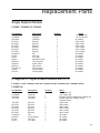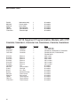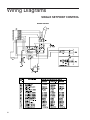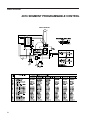
1
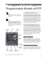
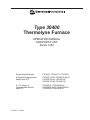
Type 30400
Thermolyne Furnace
OPERATION MANUAL
AND PARTS LIST
Series 1262
Single Setpoint Models
F30420C, F30420C-33, F30428C
8 Segment Programmable
Models with OTP
F30420C-33-80, F30420-33-60-80
F30420C-60-80, F30420C-80
F30428C-60-80, F30428C-80
4 X 16 Segment
Programmable Models
with OTP
F30430CM, F30430CM-33,
F30430CM-33-60, F30430CM-60
F30438CM, F30438CM-60
LT1262X1 • 10/8/04
Table of Contents
IMPORTANT INFORMATION
This manual contains important operating and safety information. You must carefully
read and understand the contents of this manual prior to the use of this equipment.
Safety Information ..............................................................................................................................................4
Alert Signals..................................................................................................................................................4
Warnings ......................................................................................................................................................4
General Specifications ........................................................................................................................................6
Environmental Conditions ............................................................................................................................6
Declaration of Conformity ............................................................................................................................7
Introduction..........................................................................................................................................................8
Intended Use ................................................................................................................................................8
General Usage..............................................................................................................................................8
Principles of Operation ................................................................................................................................9
Unpacking ........................................................................................................................................................10
Installation ........................................................................................................................................................11
Site Selection ..............................................................................................................................................11
Electrical Connections ................................................................................................................................11
Operation, All Models ........................................................................................................................................12
Power Switch ..............................................................................................................................................12
Cycle Light ..................................................................................................................................................12
Door Safety Switch ....................................................................................................................................12
Single Setpoint Models with OTP ....................................................................................................................13
Basic Operation ..........................................................................................................................................13
Buttons and Indicators ................................................................................................................................13
To View or Change the Setpoint ................................................................................................................14
To View the Display Units ..........................................................................................................................14
To View the % Output Power......................................................................................................................14
Controller Parameters ................................................................................................................................14
Alarms ........................................................................................................................................................15
Sensor Break Protection ............................................................................................................................16
Over Temperature Protection (OTP) ..........................................................................................................16
Tuning ........................................................................................................................................................17
Single Ramp and Dwell ....................................................................................................................................18
Functions ....................................................................................................................................................18
Program Overview ......................................................................................................................................18
Program Setup............................................................................................................................................19
Running the Program..................................................................................................................................20
Stopping the Program ................................................................................................................................20
Clearing the Flashing End ..........................................................................................................................20
Switching from Manual Mode to Automatic Mode ......................................................................................20
Verifying a Running Program......................................................................................................................20
8 Segment & 4x16 Segment Programmable Models w/OTP............................................................................21
Basic Operation ..........................................................................................................................................21
To Change the Setpoint ..............................................................................................................................21
To View the Display Units ..........................................................................................................................22
To View the % Output Power......................................................................................................................22
Buttons and Indicators ................................................................................................................................22
Controller Parameters ................................................................................................................................23
Alarms ........................................................................................................................................................26
2
TABLE
OF
CONTENTS
Sensor Break Protection ............................................................................................................................26
Over Temperature Protection......................................................................................................................27
To Operate the Controller as a Single Setpoint Controller ........................................................................27
Programming Controller..............................................................................................................................27
Creating a New Program or Editing an Existing Program ..........................................................................28
Setting the Target Setpoint ........................................................................................................................28
Running a Program ....................................................................................................................................34
Holding a Program......................................................................................................................................35
Cancelling a Program ................................................................................................................................35
Tuning Your Furnace ..................................................................................................................................35
Gain Scheduling ........................................................................................................................................36
Installation and Operation of Air Control ..........................................................................................................38
Installation ..................................................................................................................................................38
Furnace Loading ..............................................................................................................................................39
Preventative Maintenance ................................................................................................................................40
General Cleaning Instructions ....................................................................................................................40
Problem Solving ................................................................................................................................................41
Maintenance and Servicing ..............................................................................................................................44
Warning ......................................................................................................................................................44
To Replace a Heating Element ..................................................................................................................44
To Replace a Platinel II Thermocouple ......................................................................................................45
To Replace Solid State Relay ....................................................................................................................46
To Replace Door Switch (Microswitch) ......................................................................................................46
To Realign Door Strike ......................................................................................................................................47
To Replace Control Module ..............................................................................................................................48
Replacement Parts List ....................................................................................................................................49
Ordering Procedures ........................................................................................................................................51
Wiring DIagrams................................................................................................................................................52
Two Year Limited Warranty ..............................................................................................................................56
3
Safety Information
Alert Signals
Warning
Warnings alert you to a possibility of
personal injury.
Caution
Cautions alert you to a possibility of
damage to the equipment.
Note
Notes alert you to pertinent facts and
conditions.
Hot Surface
Hot surfaces alert you to a
possibility of personal injury if you
come in contact with a surface during
use or for a period of time after use.
Your Barnstead Thermolyne furnace has been designed
with function, reliability and safety in mind. It is your responsibility to install it in conformance with local electrical
codes. For safe operation, please pay attention to the
alert signals throughout the manual.
To avoid electrical shock, this furnace must:
1. Use a properly grounded electrical outlet of correct voltage and current handling capacity.
2.
Disconnect from the power supply prior to maintenance and servicing.
3.
Have the door switch operating properly.
To avoid burns, this furnace must:
1. Not be touched on the exterior or interior surfaces during use or for a period of time after
use.
To avoid personal injury:
1. Do not use in the presence of flammable or
combustible materials; fire or explosion may
result. This device contains components which
may ignite such material.
2.
Refer servicing to qualified personnel.
Warning
Please note the following WARNINGS:
This warning is presented for compliance with California
Proposition 65 and other regulatory agencies and only
applies to the insulation in this product. This product
contains refractory ceramic, refractory ceramic fiber or
fiberglass insulation, which can produce respirable dust or
fibers during disassembly. Dust or fibers can cause
irritation and can aggravate preexisting respiratory
diseases. Refractory ceramic and refractory ceramic
fibers (after reaching 1000°C) contain crystalline silica,
which can cause lung damage (silicosis). The International Agency for Research on Cancer (IARC) has classified
refractory ceramic fiber and fiberglass as possibly
4
SAFETY INFORMATION
carcinogenic (Group 2B), and crystalline silica as carcinogenic to humans (Group 1).
The insulating materials can be located in the door, the
hearth collar, in the chamber of the product or under the
hot plate top. Tests performed by the manufacturer indicate that there is no risk of exposure to dust or respirable
fibers resulting from operation of this product under normal conditions. However, there may be a risk of exposure
to respirable dust or fibers when repairing or maintaining
the insulating materials, or when otherwise disturbing
them in a manner which causes release of dust or fibers.
By using proper handling procedures and protective
equipment you can work safely with these insulating
materials and minimize any exposure. Refer to the appropriate Material Safety Data Sheets (MSDS) for information regarding proper handling and recommended protective equipment. For additional MSDS copies, or additional
information concerning the handling of refractory ceramic
products, please contact the Customer Service
Department at Barnstead International
(1-800-553-0039).
5
General Specifications
Models
F30420C, (-33),
(-33-60-80), (-33-80),
(-60-80) & (-80)
F30428C, (-60-80)
& (-80)
F30438CM & (-60)
F30430CM, (-33),
(-33-60) & (-60)
Overall Dimensions
IN. (CM)
Width
Height
Depth
21 1/2 (55)
29 1/2 (75)
25 1/2 (65)
21 1/2 (55)
29 1/2 (75)
25 1/2 (65)
Chamber Dimensions
IN. (CM
Width
Height
Depth
14 (35)
14 (35)
14 5/8 (37)
14 (35)
14 (35)
14 5/8 (37)
Weight
Lbs. (KG)
188 (86)
188 (86)
Electrical Ratings
Volts
Amps
Watts
Freq.
Phase
240
22.9
5500
50/60
1
208
26.4
5500
50/60
1
Temperature Ratings
°F (°C)
Cont.
400°F-1800°F*
(204°C)-(982°C)
400°F-1800°F*
(204°C)-(982°C)
Intermittent
1800°F-2000°F
(982°C)-(1093°C)
1800°F-2000°F
(982°C)-(1093°C)
* The maximum continuous temperature for ashing furnaces (-60 models) is 1787°F (975°C).
Environmental Conditions
Operating:
17°C - 27°C; 20% to 80% relative humidity, non-condensing. Installation Category II
(over-voltage) in accordance with IEC 664. Pollution Degree 2 in accordance with IEC 664.
Altitude limit: 2,000 meters.
Storage:
-25°C to 65°C; ; 10% to 85% relative humidity.
6
GENERAL SPECIFICATIONS
Declaration of Conformity
(for 230 volt CE models only)
Barnstead International hereby declares under its sole responsibility that this product conforms with the technical requirements of the following standards:
EMC:
EN 61000-3-2
EN 61000-3-3
EN 61326-1
Safety: EN 61010-1
EN 61010-2-010
Limits for harmonic current emissions
Limits for voltage fluctuations and flicker
Electrical equipment for measurement, control, and laboratory use; Part I:
Generic Requirements
Safety requirements for electrical equipment for measurement, control, and
laboratory use; Part I: General Requirements
Part II: Particular requirements for laboratory equipment for the heating of
materials
per the provisions of the Electromagnetic Compatibility Directive 89/336/EEC, as amended by 92/31/EEC and
93/68/EEC, and per the provisions of the Low Voltage Directive 73/23/EEC, as amended by 93/68/EEC.
The authorized representative located within the European Community is:
Electrothermal Engineering, Ltd.
419 Sutton Road
Southend On Sea
Essex SS2 5PH
United Kingdom
Copies of the Declaration of Conformity are available upon request.
7
Introduction
Intended Use
1.
The Type 30400 Automatic and Programmable
furnaces are general laboratory and heat treating furnaces. For optimum element life,
Barnstead Thermolyne recommends these furnaces for applications requiring temperatures
from 400°F (204°C) to 1800°F (982°C) for continuous use, or temperatures from 1800°F
(982°C) to 2000°F (1093°C) for intermittent use.
Continuous use is operating the furnace for
more than 3 hours and intermittent use is operating the furnace for less than 3 hours.
2.
The unit consists of 1) a heating chamber; 2) an
automatic proportioning digital set, digital read
control with overtemperature protection and 3) a
door interlock relay for user safety.
3.
The Type 30400 Programmable furnace is
designed to control a programmed temperature
profile. The profile is in the format of ramps and
dwell segments. The first ramp, RAMP 1, starts
at the initial measured furnace temperature. This
ramp is positive going at a programmed rate
until the programmed level is reached. The setpoint will stay at this level for a period determined by the setting of DWELL 1. Additional
positive or negative going ramps are now initiated starting at the level at the end of DWELL 1.
When the second ramp reaches the second programmed level, the setpoint stays at that level
for the duration of the segment. Depending
upon the model ordered, additional ramp and
dwell segments may be added. See specific
model number in proceeding chart for total number of program segments.
4.
The Type 30400 Automatic furnace is designed
as a single set point controller which reaches
and maintains one temperature value.
Note
When in the program RUN mode, the
programmable controller serves to provide a programmed temperature profile as described earlier. When in the
single setpoint automatic mode, the
unit serves as an automatic temperature controller.
General Usage
Do not use this product for anything other than its intended usage.
8
INTRODUCTION
MODEL NUMBER
DIGITAL COMMUM.
F30420C-33-80
F30420-33-60-80
F30420C-60-80
F30420C-80
F30428C-60-80
F30428C-80
F30430CM
F30430CM-33
F30430CM-33-60
F30430CM-60
F30438CM
F30438CM-60
NO
NO
NO
NO
NO
NO
YES
YES
YES
YES
YES
YES
TOTAL NUMBER OF
PROGRAMMABLE
SEGMENTS
8
8
8
8
8
8
64
16
64
16
64
16
64
16
64
16
64
16
NUMBER OF
STORED
PROGRAMS
Segment
Segment
Segment
Segment
Segment
Segment
Programs
Programs
Programs
Programs
Programs
Programs
Principles of Operation
1.
Furnace: The furnace chamber is heated by four
electric resistance heaters which are embedded in a
refractory material. The chamber is insulated with a
ceramic fiber insulation. The temperature is controlled by an automatic proportioning controller using
a platinel thermocouple to feed back information. The
control is located under the furnace chamber and is
well insulated from the heat generated in the furnace
chamber. The temperature is controlled by one of
three types of controllers.
9
Unpacking
10
1.
Visually check for any physical damage to the
shipping container.
2.
Inspect the equipment surfaces that are adjacent to any damaged area.
3.
Open the furnace door and remove the packing
material from inside the furnace chamber.
4.
Vacuum the chamber prior to use to remove the
insulation dust due to shipment.
5.
Retain the original packaging material if reshipment is foreseen or required.
Installation
Site Selection
Caution
Be sure ambient temperature does not
exceed 40°C (104°F). The recommended
ambient temperature is 17°C - 27°C.
Ambients above this level may result in
damage to the controller.
Caution
Allow at least six inches of space
between the furnace and any combustible
surface. This permits the heat from the
furnace case to escape so as not to create a possible fire hazard.
Install furnace on a sturdy surface and allow adequate
space for ventilation.
Electrical Connections
The electrical ratings are located on the specification
plate on the back of the furnace. Consult
Barnstead/Thermolyne if your electrical service is different than those listed on the specification plate. Be
sure the front power switch is in the OFF position
before connecting the furnace to your electrical supply.
Warning
To avoid electrical shock, this furnace
must always use a properly grounded
outlet of correct voltage and current handling capacity.
11
Operation, All Models
Warning
To avoid personal injury do not use in the
presence of flammable or combustible
chemicals; fire or explosion may result.
This device contains components which
may ignite such materials.
Power Switch
Both the ON/OFF power switch and the digital display
will illuminate when power is switched ON. The furnace
will begin to heat to its controller's current setpoint.
(See the instructions for your type of controller for information on checking and setting the setpoint.)
Cycle Light
Hot Surface
Caution: Avoid Contact. To avoid burns,
this furnace must not be touched on the
exterior or interior surfaces during use or
for a period of time after use.
Warning
Always wear safety glasses or a safety
shield and high temperature gloves when
loading or unloading the furnace. Long
sleeved, fire retardant clothing and a fire
retardant apron is also recommended.
Warning
To avoid electrical shock, the door safety
switch must be operating properly.
12
The amber cycle light will illuminate whenever the
power is being applied to the heating elements. The
cycle light will turn on and off as the furnace reaches
the setpoint.
Door Safety Switch
The door safety switch removes power from the heating elements when the door is opened. Open and
close the door a few times; note that the amber
CYCLE light will switch off when the door is opened. If
this condition is not true, consult the Troubleshooting
section before proceeding. This check must be done
when the furnace is heating and the cycle light is illuminated.
Single Setpoint Models w/OTP
Output 2
Output 1
Temperature
Display
Manual
The single setpoint model w/ OTP furnace controller
is a single setpoint controller which provides a single
digital display to indicate the current chamber temperature or setpoint temperature. This temperature controller features sensor break protection, self-tuning
capability and over temperature protection (OTP) with
an additional OTP relay device.
Display
Window
Basic Operation
MAN
When the controller is turned ON it will perform a short
self-test and then display the measured value (process
value) in the HOME DISPLAY.
Buttons and Indicators
PAGE
Button
SCROLL
Button
DOWN ARROW
Button
UP ARROW
Button
Single Setpoint Models
OP1 (Output 1): Illuminates when the logic output is
ON.
OP2 (Output 2): Illuminates when the relay output is
ON (will go out during an alarm situation).
PAGE button: Allows you to select a new list of
parameters.
SCROLL button: Allows you to select a parameter
within a list of parameters.
DOWN button: Allows you to decrease a value.
UP button: Allows you to increase a value.
Note
If at any time you want to return to the
HOME DISPLAY, simultaneously press
the PAGE and SCROLL buttons.
13
SINGLE SETPOINT MODELS
W/OTP
To View or Change the Setpoint
To view the setpoint, press and release the UP or DOWN
buttons. If you want to change the setpoint, continue pressing until the desired setpoint value is displayed and then
release the button. A few seconds after the button is
released, the controller will accept the new value and revert
to the HOME DISPLAY.
To View the Display Units
From the HOME DISPLAY press the SCROLL button. The
display will show the temperature units in °C/F/K and then
return to the HOME DISPLAY. (Call Customer Service if you
require a different temperature unit.)
To View the % Output Power
From the HOME DISPLAY press the SCROLL button twice.
Press and release the UP or DOWN button to view the %
output power. This value is a read-only value and cannot be
changed.
Controller Parameters
Home display
°C: Temperature units in Celsius. Temperature units can not
be changed without entering the configuration. Contact
Customer Service if a different temperature unit is required.
OP: % output power demand.
IdHi: Deviation high alarm.
Al List
IdHi: Deviation high alarm.
Atun List
tunE: One-shot autotune enable.
14
SINGLE SETPOINT MODELS
W/OTP
Pid List
Pb: Proportional band (in display units).
ti: Integral time in seconds.
td: Derivative time in seconds.
ACCS List Code: Access code (Code needed to enter or
change the other configuration parameters which are not
normally accessible.) Not accessable.
Note
The following alarm messages are
factory default settings and may vary
if you have changed the configuration
of your controller:
IDHi: = 50°C
2FSH = 1118°C
Alarms
The controller will flash an alarm message in the home
display if an alarm condition is detected.
2FSH: Measured value full scale high alarm.
IdHi: Measured value deviation high alarm.
S.br: Sensor break: check that sensor is connected correctly.
L.br: Loop break: check that the heating circuits are working properly.
Ld.F: Heater Circuit fault: indication of either an open or
short solid sate relay, a blown fuse, missing supply or
open circuit heater.
15
SINGLE SETPOINT MODELS
W/OTP
Sensor Break Protection
This controller provides sensor break protection in the
event the thermocouple opens. If an open thermocouple condition occurs, the digital display will blink “S.br”
and the power to the heating element will be shut OFF
(Cycle light will extinguish).
Over-Temperature Protection
(OTP)
The OTP will be in effect during any alarm condition
when the temperature of the furnace has deviated
beyond the limit. The “Deviation High” alarm is the only
alarm value which can be changed. To change it, press
the SCROLL button until “IdHi” appears on the display.
Press the UP or DOWN button to select the OTP value
you desire. We recommend a value of 20° above your
working temperature to provide protection for your
workload.
In addition to over-temperature protection, units containing a single setpoint controller w/OTP feature a
mechanical OTP relay device which disconnects power
from the elements in an alarm condition (only in furnaces with OTP relay). See models listed on front
page.
16
SINGLE SETPOINT MODELS
W/OTP
Tuning
Note
Furnace must be at ambient
temperature before starting a tune.
Note
“Stat” and “Sp.rr” in Sp list must be
set to OFF or “tunE” will not initiate.
This controller incorporates a self-tuning feature which
determines the optimum control parameters for the
best temperature accuracy with your load and setpoint.
Use this feature the first time you use your furnace and
each time you change either your setpoint or the type
of load you are heating. Barnstead|Thermolyne recommends you use this feature to provide the best temperature accuracy the controller can attain. To use the tuning feature:
1. Adjust the setpoint to your desired value.
2.
Press the PAGE button until display reads,
“Atun.”
3.
Press the SCROLL button. Display will read,
“tunE.”
4.
Press the UP or DOWN button to select, “on.”
5.
Simultaneously press the PAGE and
SCROLL buttons to return to the HOME DISPLAY. The display will alternately flash
between “tunE” and the HOME DISPLAY
while tuning is in progress.
6.
The controller will then turn the heating on
and off to induce an oscillation. When the
measured value reaches the required setpoint
the first cycle will end.
7.
Tuning will be complete after two oscillation
cycles and then the tuner will turn itself off.
8.
Normal control function will resume after the
controller calculates tuning parameters.
Note
Tune has completed when “tunE”
stops flashing on display.
17
Single Ramp & Dwell
Note
These instructions are used with the Single Setpoint models with OTP only
(See models listed on front page).
Functions
This type of controller has single ramp and dwell programming capabilities. The Ramp and Dwell can be configured
to five different modes.
1.
Mode 1 (Opt. 1) is a Ramp (if needed) to the
Setpoint temperature, a Dwell, and then a cool
down.
2.
Mode 2 (Opt. 2) is the same as mode 1, except
the controller continues to heat at the Setpoint
after the Dwell has completed. (This mode does
not cool down.)
3.
Mode 3 (Opt. 3) is the same as mode 1, except
the Dwell time includes the Ramp (if needed).
4.
Mode 4 (Opt. 4) is the same as mode 2, except
the Dwell time includes the Ramp (if needed).
5.
Mode 5 (Opt. 5) is a Dwell (delay time) before the
controller Ramps (if needed) to the Setpoint temperature.
Mode 1 (Opt. 1)
Mode 2 (Opt. 2)
Mode 3 (Opt. 3)
Mode 4 (Opt. 4)
Mode 5 (Opt. 5)
18
Program Overview
•
A program mode can be set by changing the
“tm.OP” variable to “Opt. 1, Opt. 2, Opt. 3, Opt. 4,
or Opt. 5.
•
A Ramp rate may be set by changing the “SPrr”
variable to a value. The Ramp rate units are in
degrees per minute.
•
The Dwell time can be set by changing the
“dwEll” variable to the desired value. Dwell time
units are in minutes.
•
The program Status can be set by changing the
“StAt” variable to “run” or “oFF.” This variable will
start or stop the program.
SINGLE RAMP & DWELL CONTROLLER
Program Setup
Note
The program must be stopped and
the controller must be displaying the
actual temperature before beginning
the Setup.
1.
Press the PAGE button until the “SP” is displayed.
2.
Press the SCROLL button once, “SPrr” (Ramp Rate)
will be displayed, set the desired Ramp rate with the
UP or DOWN buttons, if the ramp to setpoint feature is
needed. If the Ramp rate is not needed, then set to
“OFF” with the UP or DOWN buttons.
3.
Press the SCROLL button once, “tm.OP” (Ramp &
Dwell mode) will be displayed, select the desired
mode with the UP or DOWN buttons. (Opt. 1, Opt. 2,
Opt. 3, Opt. 4, Opt. 5)
4.
Press the SCROLL button once, “dwEll” will be displayed, set the desired Dwell time with the UP or
DOWN buttons. (Dwell in minutes.)
5.
Press the PAGE button until the Actual temperature is
displayed.
Running the Program
1.
Press the SCROLL button until “StAt” is displayed, set
to “run” with the UP or DOWN buttons.
2.
Press the PAGE button to display Actual temperature.
Stopping the Program
Press the SCROLL button until “StAt” is displayed, set to “oFF”
with the UP or DOWN buttons.
Clearing the Flashing End
Press the PAGE and SCROLL buttons at the same time.
19
SINGLE RAMP & DWELL CONTROLLER
Verifying a Running Program
Press the SCROLL button until “StAt” is displayed.
The display will show “run” if the program is running, or
“oFF” if it is not running. Press the PAGE button to display Actual temperature.
20
8 Segment & 4x16 Segment
Programmable Models w/OTP
Note
The controller will return to the HOME
DISPLAY if left idle for more than a few
seconds.
Note
Once the desired parameter has been
selected, depressing either the UP or
DOWN button will change the parameter
value. In all cases, the value shown on
the display is the current working value of
that parameter.
AUTO/MAN
Button
Output 1
Display
Window
Upper
Display
Lower
Display
RUN/HOLD
Button
UP ARROW
Button
PAGE
Button
SCROLL
Button
DOWN ARROW
Button
The 8 segment programmable controller consists of
a microprocessor based three-mode PID
(Proportional, Integral, Derivative), programmable
temperature controller with over-temperature protection and appropriate output switching devices to control the furnace. The digital readout continuously displays chamber (upper display) and setpoint (lower
display) temperatures unless the SCROLL or PAGE
button is depressed. The programmable controller can
be used as a single setpoint controller or as a programmable controller. The 8 segment digital model
enables eight segments of programming.
The 4x16 segment programmable controller consists of a microprocessor based three-mode PID
(Proportional, Integral, Derivative), programmable
temperature controller with over-temperature protection and appropriate output switching devices to control the furnace. The digital readout continuously displays chamber (upper display) and setpoint (lower
display) temperatures unless the SCROLL or PAGE
button is depressed. The programmable controller can
be used as a single setpoint controller or as a programmable controller. The 4 program controller has
four 16 segment programs.
Basic Operation
When the controller is turned ON, it will perform a
short self-test and then change to the HOME DISPLAY. The HOME DISPLAY shows the measured
temperature (process value) in the upper display and
the desired value (setpoint) in the lower display.
To Change the Setpoint
If you want to change the setpoint, press the UP or
DOWN button until the desired setpoint value is displayed in the lower display and then release the button.
4x16 & 8 Segment Programmable Models with OTP
21
8 SEGMENT & 4X16 SEGMENT PROGRAMMABLE MODELS
W/OTP
To View Display Units
From the HOME DISPLAY press the SCROLL button. The
display will briefly show the temperature units in °C/F/K
and then return to the HOME DISPLAY. (If you require a
different temperature unit call Barnstead|Thermolyne
Customer Service.)
To View the % Output Power
From the HOME DISPLAY press the SCROLL button
twice. This value is a read-only value and cannot be
changed.
Buttons and Indicators
OP1 (Output 1): illuminates when the heating output of
the temperature controller is on.
AUTO/MAN: (Auto/Manual Mode): when the controller is
in the automatic mode the output automatically adjusts to
keep the temperature or process value at the setpoint.
The “AUTO” light will illuminate. The manual mode has
been disabled through factory configuration. Call
Customer Service for further information.
RUN/HOLD (Run/Hold button):
•
Starts a program when pressed once—RUN
light illuminates.
22
•
Holds a program when pressed again—HOLD
light illuminates.
•
Cancels hold and continues running when
pressed again—HOLD light is off and RUN light
illuminates.
•
Exits a program when the button is held down
for two seconds—RUN and HOLD lights are off.
•
At the end of a program the RUN light will flash.
•
During holdback the HOLD light will flash.
8 SEGMENT & 4X16 SEGMENT PROGRAMMABLE MODELS
W/OTP
PAGE button: allows you to choose a parameter from a
list of parameters.
SCROLL button: allows you to choose a parameter within
a list of parameters.
UP button: allows you to increase the value in the lower
display.
DOWN button: allows you to decrease the value in the
lower display.
Controller Parameters
Home Display
°C: measured temperature in Celsius. Temperature units
can not be changed without entering the configuration.
Contact Customer Service if a different temperature unit is
required.
OP: % output power demand; displayed in lower display
(cannot be changed).
C.id: Controller identification number.
PrG: Program number (displayed when a program is running; 4x16 programmable models only.)
IdHi: Deviation High Alarm
tunE: One-shot autotune enable.
run LiSt (Program Run List)
PrG: Currently running program (only used on 4x16 programmable models)
StAt: Displays the program status [OFF, run (running
active program), hoLd (program on hold), HbAc (waiting for
process to catch up), End (program completed)] in the
lower display. The controller will default to “OFF.”
FASt: Fast run through program (no/YES). The controller
will default to “no.”
SEG.d: Flash active segment type in the lower display of
the home display (no/YES). The controller will default to
“no.”
23
8 SEGMENT & 4X16 SEGMENT PROGRAMMABLE MODELS
W/OTP
ProG LiSt (Program Edit List)
PrG.n: Press the UP or DOWN ARROW to select the
program number (program number will be displayed in
lower display on 4x16 programmable models only.)
Hb: Press the UP or DOWN ARROW to select the
holdback type [OFF (disables holdback), Lo (deviation
low holdback), Hi (deviation high holdback) or bAnd
(deviation band holdback)] for the entire program. The
controller will default to “OFF.”
Hb.U: Press the UP or DOWN ARROW to select the
holdback value (in display units).
rmP.U: Press the UP or DOWN ARROW to toggle
between ramp units (SEc, min or Hour). Controller will
default to “SEc.”
dwL.U: Press the UP or DOWN ARROW to toggle
between dwell units (SEc, min or Hour). Controller will
default to “SEc.”
Cyc.n: Press the UP or DOWN ARROW to set the
number of program cycles (1 to 999 or cont). The controller will default to “cont.”
SEG.n: Press the UP or DOWN ARROW to select the
segment number (1-8 in 8 segment models, 1-16 in
4x16 models).
tYPE: Press the UP or DOWN ARROW to select the
segment type [End (end of program), rmP.r = ramp rate
(ramp to a specified setpoint at a set rate), rmp.t =
ramp time (ramp to a specified temperature in a set
time), dwEll (to maintain a constant temperature for a
set time), StEP (climb instantaneously from current to
specified temperature), cALL (to call a program as a
subroutine, available only on 4x16 programmable models)]. The controller will default to “End.” Other parameters used with tYPE include; tGt target setpoint), Rate
(rate of temperature increase) and dur (time to target
setpoint or time to dwell).
End.t: End segment type: dwELL (dwell continuous),
rSEt (reset) and S OP (End Segment Output power
level.
24
8 SEGMENT & 4X16 SEGMENT PROGRAMMABLE MODELS
W/OTP
AL LiSt (Alarm List)
IdHi: Deviation High Alarm.
Atun LiSt: (Autotune List)
tunE: One-shot autotune enable.
drA: Adaptive tune enable.
drA.t: Adaptive tune trigger level in display units.
Range = 1 9999.
Pid LiSt
G.SP (Gain Setpoint): Is the temperature at which the
controller switches from the (SEt1) PID values to the
(SEt 2) PID values.
Pb: Proportional band in display units. (SEt 1)
ti: Integral time in seconds. (SEt 1)
td: Derivative time in seconds. (SEt 1)
Pb2: Proportional band. (SEt 2)
ti2: Integral time in seconds. (SEt 2)
td2: Derivative time in seconds. (SEt 2)
ACCS LiSt (Access List)
Access Code (Code needed to enter or change the
other configuration parameters which are not normally
accessible.) Not accessable.
25
8 SEGMENT & 4X16 SEGMENT PROGRAMMABLE MODELS
W/OTP
Alarms
Note
The following alarm messages are factory
default settings and may vary if you have
changed the configuration of your
controller:
The controller will flash an alarm message in the home
display if an alarm condition is detected.
IdHi: PV deviation high alarm.
2FSH: PV full scale high alarm.
IDHi: =
50°C
2FSH = 1118°C (all models
except -60)
2FSH = 1000°C (-60 models only)
LCr: load current low alarm.
HCr: load current high alarm.
S.br: Sensor break: check that sensor is connected
correctly.
L.br: Loop Break: Check that the heating circuits are
working properly.
Ld.F: Heater Circuit Fault: indication of either an open
or short solid sate relay, a blown fuse, missing supply
or open circuit heater.
SSr.F: Solid state relay failure indications in a solid
state relay: indicates either an open or short circuit in
the SSR.
Htr.F: Heater failure: Indication that there is a fault in
the heating circuit: indicates either a blown fuse, missing supply or open circuit heater.
Sensor Break Protection
This controller provides sensor break protection in the
event the thermocouple opens. If an open thermocouple condition occurs, the digital display will Blink “S.br”
and the power to the heating element will be shut OFF
(Cycle light will extinguish).
26
8 SEGMENT & 4X16 SEGMENT PROGRAMMABLE MODELS
W/OTP
Over-Temperature Protection
(OTP)
The OTP will be in effect during any alarm condition
when the temperature of the furnace has deviated
beyond the limit. The “Deviation High” alarm is the only
alarm value which can be changed. To change it, press
the SCROLL button until “idHi” appears on the display.
Press the UP or DOWN button to select the OTP value
you desire. We recommend a value of 20° above your
working temperature to provide protection for your
workload.
To Operate the Controller as a
Single Setpoint Controller
1.
Switch the circuit breaker to the “ON” position. The setpoint temperature presently set in
the controller will appear in the lower display.
(The upper display indicates the actual chamber temperature.)
2.
To change the setpoint, press the UP or
DOWN button until the desired setpoint value
is displayed; then release the button.
3.
The furnace will begin to heat if the new setpoint temperature is higher than the present
chamber temperature.
Programming the Controller
The controller is capable of varying temperature or
process value with time through programming. A program is stored as a series of segments and can be run
once, repeated a set number of times or run continuously. To create a customized program using the controller parameters listed under “Controller Parameters”
at the beginning of this section, follow the procedures
outlined in the proceeding sections of this manual.
27
8 SEGMENT & 4X16 SEGMENT PROGRAMMABLE MODELS
W/OTP
Creating a New Program or Editing an
Existing Program (4x16 Segment
Programmable Models Only)
The same steps are used when creating a new program and editing an existing program with the exception being that a new program starts with all its segments set to End in the tYPE parameter. Temporary
changes can be made to these parameters when the
program is in the hold state but permanent changes
must be made in the reset state. Follow the steps
below to create or edit a program.
1. Press the PAGE button until you reach the
program list (ProG LiSt).
2.
Press the SCROLL button until display reads,
“PrG.n.”
3.
Press the UP or DOWN button to select a
number for a new program or to edit an existing program.
Hb: Holdback
Holdback consists of a value and a type. If the measured value lags behind the setpoint by an undesirable
amount during a ramp or dwell, the holdback feature
can be used to freeze the program at its current state
(the HOLD light will flash). The program will resume
when the error comes within the holdback value.
OFF: holdback is disabled.
Lo (Deviation Low Holdback): holds the program
back when process variable deviates below the setpoint by more than the holdback value.
Hi (Deviation High Holdback): holds the program
back when process variable deviates above the setpoint by more than the holdback value.
28
8 SEGMENT & 4X16 SEGMENT PROGRAMMABLE MODELS
W/OTP
bAnd (Deviation Band Holdback): combines the features of the high and low deviation holdback in that it
holds the program back when the process variable
deviates above or below the setpoint by more than the
holdback value.
To set the holdback type:
1. Press the PAGE button until you reach the
program list (ProG LiSt).
2.
Press the SCROLL button until display reads,
“Hb.”
3.
Press the UP or DOWN button to toggle
between “bAnd, Hi, Lo and OFF.”
Note
The value set in this parameter is always
Hb U: Holdback Value
for the entire program.
To set the holdback value:
1. Press the PAGE button until you reach the
program list (ProG LiSt).
2.
Press the SCROLL button until display reads,
“Hb.U.”
3.
Press the UP or DOWN button to enter a
holdback value.
rmP.U: Setting Ramp Units
Ramp units are time units which are used in “rmP.r”
segments (ramp to a setpoint at degrees per second,
minute or hour) and “rmP.t” segments (ramp to setpoint
in a specific amount of time). See “Setting the
Segment Type” for an explanation on how to set a
ramp segment.
1. Press the PAGE button until you reach the
program list (ProG LiSt).
2.
Press the SCROLL button until display reads,
“rmP.U.”
3.
Press the UP or DOWN button to toggle
between seconds, minutes and hours.
29
8 SEGMENT & 4X16 SEGMENT PROGRAMMABLE MODELS
W/OTP
dwL.U: Setting Dwell Units
Dwell units are time units which are used in “dwELL” segments (amount of time to remain at a specific temperature
). See “Setting the Segment Type” for an explanation on
how to set a dwell segment.
1. Press the PAGE button until you reach the program list (ProG LiSt).
2.
Press the SCROLL button until display reads,
“dwL.U.”
3.
Press the UP or DOWN button to toggle between
seconds, minutes and hours.
CYC.n: Setting the Number of Cycles
Set the number of times a group of segments or programs
are to be repeated by following the steps listed below.
1. Press the PAGE button until you reach the program list (ProG LiSt).
Note
The program ramp rate is designed to
reduce the heatup rate or cooling rate
that the furnace normally exhibits.
When not using this feature, the furnace will operate at its maximum
heating and cooling capability.
2.
Press the SCROLL button until display
reads,”CYC.n.”
3.
Press the UP or DOWN button to select the number of cycles you want to run or, press the DOWN
button to select “cont.” so the program will run
continuously.
Setting the Segment Type
There are five segment types. Proceed with the following
steps according to the type of segment you have selected.
Note
When the program ramp has ended
or has been reset, the furnace will
continue to maintain setpoint temperature. It will not cool to ambient temperature unless the setpoint is set to
ambient temperature by the program
or by the operator.
30
rmP.r (Ramp)
To ramp linearly at a set rate to a specified temperature:
1. Press the PAGE button until you reach the program list (ProG LiSt).
2.
Press the SCROLL button until display
reads,”tYPE.”
3.
Press the UP or DOWN button until display
reads, “rmP.r.”
8 SEGMENT & 4X16 SEGMENT PROGRAMMABLE MODELS
W/OTP
Steps 4 and 5 are used in the 4 program model only. If
you are using an 8 segment program, skip to step 6.
4.
Press the SCROLL button until display reads
“Hb.”
5.
Press the UP or DOWN button to toggle
between “bAnd, Hi, Lo and OFF.”
6.
Press the SCROLL button until display reads,
“tGt.”
7.
Press the UP or DOWN button to set a target
setpoint.
8.
Press the SCROLL button until display
reads,”rAtE.”
9.
Press the UP or DOWN button to select a
value in ramp units (seconds, minutes or
hours; set in the “rmP.U” parameter).
rmP.t
To ramp to a specified temperature at a set time:
1. Press the PAGE button until you reach the
program list (ProG LiSt).
2.
Press the SCROLL button until display reads,
“tYPE.”
3.
Press the UP or DOWN button until display
reads, “rmP.t.”
4.
Press the SCROLL button until display reads,
“tGt.”
5.
Press the UP or DOWN button to set a target
setpoint.
6.
Press the SCROLL button until display reads,
“dur.”
7.
Press the UP or DOWN button to select a
time in ramp units (seconds, minutes or
hours; set in the “rmP.U” parameter.
31
8 SEGMENT & 4X16 SEGMENT PROGRAMMABLE MODELS
W/OTP
dwEll
To maintain a constant temperature for a specified time:
1. Press the PAGE button until you reach the program list (ProG LiSt).
2.
Press the SCROLL button until display reads,
“tYPE.”
3.
Press the UP or DOWN button until display
reads, “dwEll.”
4.
Press the SCROLL button until display reads,
“dur.”
5.
Press the UP or DOWN button to select a time in
dwell units (seconds, minutes or hours; set in the
“dwL.U” parameter).
StEP
To climb instantaneously from the current temperature to a
specified temperature.
1. Press the PAGE button until you reach the program list (ProG LiSt).
2.
Press the SCROLL button until display reads,
tYPE.”
3.
Press the UP or DOWN button until the display
reads, “StEP.”
4.
Press the SCROLL button until display reads,
“tGt.”
5.
Press the UP or DOWN button to set a target setpoint.
cALL (Running Multiple Programs; 4x16 Segment
Programmable Models Only)
To call a program as a subroutine:
If you want to run multiple programs, you can program the
controller to “call” or link one program to another. This
makes it possible to run one program at any time during
another program and also return to the original program if
desired.
1. Press the PAGE button until you reach the program list (ProG LiSt).
32
8 SEGMENT & 4X16 SEGMENT PROGRAMMABLE MODELS
W/OTP
2.
Press the SCROLL button until display reads,
“tYPE.”
3.
Press the UP or DOWN button until display
reads, “cALL.”
4.
Press the SCROLL button until display reads,
“PrG.n.”
5.
Press the UP or DOWN button to select a program number to be linked.
6.
Press the SCROLL button until display reads,
“CYC.n.”
7.
Press the UP or DOWN button to select the
number of cycles the linked program is to be
run.
End
To end or repeat a program:
1. Press the PAGE button until you reach the program list (ProG LiSt).
2.
Press the SCROLL button until display reads,
“tYPE.”
3.
Press the UP or DOWN button until display
reads, “End.”
4.
Press the SCROLL button until display reads,
“End.t.”
5.
Press the UP or DOWN button to toggle
between “dwEll” (an indefinite dwell), “S OP”
(End Segment Output Power) and “rSET”
(reset).
33
8 SEGMENT & 4X16 SEGMENT PROGRAMMABLE MODELS
W/OTP
Setting the Target Setpoint (4x16
Segment Programmable Models Only)
1.
Press the PAGE button until you reach the
program list (ProG LiSt).
2.
Press the SCROLL button until display reads,
“tGt.”
3.
Press the UP or DOWN button to set the target setpoint temperature.
Running a Program (8
Segment Programmable
Models)
To run a program, press the RUN/HOLD button. (The
RUN light will illuminate.)
Running a Program (4x16
Segment Programmable
Models)
To run a program, press the RUN/HOLD button. (The
RUN light will illuminate) or:
1. Press the PAGE button until you reach the run
list (run LiSt).
34
2.
Press the SCROLL button until display reads,
“PrG.”
3.
Press the UP or DOWN button to select the
program number you want to run.
4.
Press the RUN/HOLD button once to start the
program. (The RUN light will illuminate.)
Holding a Program
To put a running program on hold, press the RUN/HOLD
button. (The HOLD light will illuminate.)
Cancelling a Program
To cancel a program, hold the RUN/HOLD button down
until the RUN and HOLD lights go off.
Note
Display will flash “tu.ER” if an error
occurs during tuning. To clear the
error and restart tuning, simultaneously press the PAGE and SCROLL
buttons and follow the steps outlined
in “Autotuning.”
Note
To stop the tuning function, simultaneously press the PAGE and
SCROLL buttons.
Tuning your Furnace
The purpose of tuning your furnace is to match the characteristics of your controller to the characteristics of the
process being controlled. Good control is evidenced by:
stable, straight-line control of the setpoint temperature
with no fluctuations; No overshoot or undershoot of the
setpoint temperature; rapid restoration of the setpoint
temperature when external disturbances cause deviations
from the setpoint.
This controller has automatic tuning features which install
optimum tuning parameters to give the best temperature
accuracy. No manual loading of tuning parameters is
needed. We recommend that you tune the furnace to your
specific application to obtain the best results. To provide
the best temperature accuracy possible, use these features when you install your furnace and whenever you
change your application or procedure.
Tuning Error
The display will flash “tu.ER” if an error occurs during tuning. To clear the error and restart tuning, simultaneously
press the PAGE and SCROLL buttons and follow the
steps outlined in “Autotuning.”
35
8 SEGMENT & 4X16 SEGMENT PROGRAMMABLE MODELS
W/OTP
Gain Scheduling
G.SP: Gain Scheduling
Gain scheduling is the automatic transfer of control
between two sets of PID values. The 2416 controller
does this at a presettable process value. Gain scheduling is used for difficult control processes which show
large changes in their response time or sensitivity at
high or low temperatures, or when heating or cooling.
The G.SP gain schedule setpoint is factory set at 700°
C. The G.SP must be adjusted to 200°C from the
desired setpoint temperature when tuning.
Setting the Transfer Point
If gain scheduling has been enabled, “G.SP will appear
at the top of the PID list. This sets the value at which
the transfer will occur. When the process value is
below this level, PID1 will be active and when it is
above, Pid2 will be active. Set a value between the
control regions that show the greatest change to
achieve the best point of transfer.
Tuning
The two sets of PID values can be manually set or
automatically tuned. To tune automatically you must
tune above and below the transfer point G.SP. If the
process value is below the transfer point G.SP, the calculated values will automatically be inserted into the
(SEt 1) set and if the process value is above G.SP, the
calculated values will automatically be inserted into the
(SEt 2).
Autotuning
The Autotune feature automatically sets up the PID values in the control parameters to suit new process conditions.
To tune your furnace using autotuning:
1. Load your furnace with a load similar to your
normal load and close the door.
36
8 SEGMENT & 4X16 SEGMENT PROGRAMMABLE MODELS
W/OTP
2.
Set the setpoint temperature.
3.
Press the PAGE button until the display reads,
“Atun LiSt.”
4.
Press the SCROLL button until “tunE OFF” is
displayed.
5.
Press the UP or DOWN button to select “on.”
6.
Simultaneously press the PAGE and SCROLL
buttons to return to the HOME DISPLAY. The
display will flash “tunE” while tuning is in
progress.
Adaptive Tuning
Adaptive tuning continuously evaluates tuning parameters. Adaptive tuning automatically installs new values if
better accuracy is possible. Adaptive tuning should be
used when the characteristics of a process change due to
load or setpoint changes or, in a process that can not
handle the oscillation caused by a one-shot tune.
To tune your furnace using adaptive tuning:
1. Load your furnace with a load characteristic of
those you intend to heat in it.
2. Press the PAGE button until display reads, “Atun
LiSt.”
3.
Press the SCROLL button until “drA OFF” is displayed.
4.
Press the UP or DOWN button to select “on.”
5.
Press the SCROLL button until “drA.t” is displayed.
6.
Press the UP or DOWN button until the desired
trigger value is achieved.
37
Installation and Operation of
Air Control
Models F30420-33-60-80, F30420C-60-80,
F30428C-60-80, F30430CM-33-60, F30430CM60, F30438CM-60
Installation
Note
Ashing furnaces -60 models contain a
feature to provide air (or inert gas)
flow within the furnace chamber.
Note
A pressurized air line with a minimum
working pressure range of 0 to 40 psi
is required.
Note
If furnace is to be used regularly, the
airline regulator may be left open to 30
psi.
Note
Appropriate exhaust must be provided
to remove smoke and gases produced
in an ashing procedure.
Compressed air hook-up
1.
A 0.250 inch tube fitting is located at the rear of
the furnace.
2.
Using 0.250 inch I.D. rubber tubing, connect a
length of tubing from this input fitting to a corresponding 0.250 inch fitting located on the regulated side of a pressurized air service line.
3.
Prior to making connections at the regulator,
insure that the regulator is turned fully closed (0
psi).
4.
Turn flow control valve located at the bottom of
the flow meter (front control panel) fully clockwise
to closed position.
5.
Turn regulator to maximum output pressure of 30
psi. Check for any leaks at connection points of
connecting tubing.
6.
Open flow control valve slowly until ball in flow
meter reads between 40 to 45 liters per minute
flow rate.
7.
Open furnace door and check that air is exhausting from the manifold located at the bottom rear
of the chamber.
8.
Turn flow control valve to off (fully clockwise).
Exhaust tubing hook-up
38
Using accessory tubing available from Barnstead
International (part number AY408X1A for furnace temperatures less than 975°C, part number AY718X1 for furnace
temperatures of 975°C or greater) or equal quality 2.5" I.D.
tubing appropriate for the temperatures at which you will
operate your furnace, connect flexible tubing from vent port
at top of furnace case to an appropriate negative pressure
exhaust system. This exhaust system must be capable of
handling smoke and gases produced in an ashing procedure.
Furnace Loading
Note
Failure to connect the exhaust port to
an appropriate exhaust system will result in smoke and gases filling the
work area. Without the connection,
gases and smoke will escape around
the door seal and at the rear of the
furnace.
Caution
Do not overload your furnace chamber. If the load is to be heated uniformly it should not occupy more than twothirds of the furnace chamber. Failure
to observe this caution could result in
damage to furnace components.
•
For best results, use only the center two-thirds
of the furnace chamber.
•
Use Hearth plate to elevate load when placing
on bottom heating element. This prevents bottom heating element from overheating and burning out. (Part Numbers PHX1 & PHX2)
•
If you are heating a number of small parts,
spread them throughout the center of the furnace chamber.
•
Keep objects away from thermocouple.
•
Use insulated tongs and mittens when loading
and unloading furnace.
•
Always wear safety glasses.
39
Preventative Maintenance
This unit is equipped with a venting system on the top of
the furnace. This is for the removal of fumes from the
chamber of the unit. Contamination is a major cause of element failure, therefore, remove all fume forming material
before heating. (e.g. clean cutting oil from tool steel).
Housekeeping is vital to your electric furnace - KEEP IT
CLEAN. Run your furnace up to 1600°F empty occasionally to burn off the contamination that may exist on the insulation and elements. Maintain 1600°F for at least 4
hours to insure complete ashing of foreign materials.
Element life is reduced somewhat by repeated heating
and cooling. If the furnace is to be used again within a
few hours, it is best to keep it at the operating temperature or at a reduced level such as 500°F (260°C).
General Cleaning Instructions
Wipe exterior surfaces with lightly dampened cloth containing mild soap solution.
40
Problem Solving
The Problem Solving section is intended to aid in defining and correcting possible service problems. When
using the chart, select the problem category that resembles the malfunction. Then proceed to the possible
causes category and take necessary corrective action.
Problem
Probable Causes
Corrective Action
The cycle light does
not illuminate.
The furnace is not connected to
power supply.
Check furnace connection
to power source.
ON and OFF power switch is
defective.
Replace power switch.
Door switch defective.
Realign door strike or
replace door safety switch.
Incorrect power source.
Check power source.
Defective circuit breaker.
Replace circuit breaker.
No power.
Check power source and fuses or
breakers.
Defective electrical hookup.
Repair electrical hookup.
Thermocouple has oxidized
and opened the circuit.
Replace thermocouple.
Controller malfunction.
Contact customer service.
Two or more heating elements
burned out.
Replace defective elements.
Door switch malfunction.
Realign door strike or replace door
safety switch.
Defective safety relay.
Replace safety repay.
Defective solid state relay (SSR)
Replace SS relay.
The furnace does not heat.
41
PROBLEM SOLVING
Problem
Probable Causes
Corrective Action
Slow heatup.
Low line voltage.
Install line of sufficient size
and proper voltage (Isolate
furnace from other electrical loads).
Heavy load in chamber.
Lighten load in chamber
to allow heat to circulate.
Wrong heating element
Install proper element.
One or more heating
elements are burned out.
Replace burned out elements.
Wired improperly.
Check wiring diagram for
correct wiring of your furnace.
Door switch is not functioning.
Realign door strike or
replace door safety switch.
Safety relay malfunction.
Replace safety relay.
Overheating furnace.
Do not exceed the maximum
operating temperature of
furnace or recommended
continuous intermittent use
values.
Heating harmful materials.
Enclose material in container.
Clean up spills on chamber.
Ventilate chamber by leaving door
cracked slightly open when heating
known harmful reagents.
Door switch does not cut
power to the furnace chamber.
Repeated element burnout.
42
PROBLEM SOLVING
Problem
Inaccurate.
Probable Causes
Corrective Action
Contamination present from
previous burnout.
Clean and/or replace insulation
material.
Wired improperly.
Check wiring diagram for
correct wiring of your furnace.
Oxidized or contaminated
thermocouple.
Replace thermocouple.
Poor thermocouple connections.
Tighten connections.
Improper loading.
Use proper loading procedures.
Poor ventilation of base.
Clear area around furnace base.
Control out of calibration.
Contact customer service.
43
Maintenance and Servicing
Warning
Refer servicing to qualified personnel.
Warning
Replace fuses with same type and
rating.
Warning
This product contains refractory
ceramic, refractory ceramic fiber or
fiberglass insulation, which can produce respirable dust or fibers during
disassembly. Dust or fibers can cause
irritation and can aggravate preexisting
respiratory diseases. Refractory
ceramic and refractory ceramic fibers
(after reaching 1000°C) contain crystalline silica, which can cause lung
damage (silicosis). The International
Agency for Research on Cancer
(IARC) has classified refractory ceramic fiber and fiberglass as possibly
carcinogenic (Group 2B), and crystalline silica as carcinogenic to
humans (Group 1).
Warning
To avoid electrical shock, this furnace
must always be disconnected from the
power supply prior to maintenance
and service.
Perform only maintenance described
in this manual. Contact an authorized
dealer or our factory for parts and assistance.
44
Warning
Please note the following WARNINGS:
This warning is presented for compliance with California
Proposition 65 and other regulatory agencies and only
applies to the insulation in this product. This product
contains refractory ceramic, refractory ceramic fiber or
fiberglass insulation, which can produce respirable dust or
fibers during disassembly. Dust or fibers can cause
irritation and can aggravate preexisting respiratory
diseases. Refractory ceramic and refractory ceramic
fibers (after reaching 1000°C) contain crystalline silica,
which can cause lung damage (silicosis). The International Agency for Research on Cancer (IARC) has classified
refractory ceramic fiber and fiberglass as possibly
carcinogenic (Group 2B), and crystalline silica as
carcinogenic to humans (Group 1).
The insulating materials can be located in the door, the
hearth collar, in the chamber of the product or under the
hot plate top. Tests performed by the manufacturer
indicate that there is no risk of exposure to dust or
respirable fibers resulting from operation of this product
under normal conditions. However, there may be a risk of
exposure to respirable dust or fibers when repairing or
maintaining the insulating materials, or when otherwise
disturbing them in a manner which causes release of dust
or fibers. By using proper handling procedures and
protective equipment you can work safely with these
insulating materials and minimize any exposure. Refer to
the appropriate Material Safety Data Sheets (MSDS) for
information regarding proper handling and recommended
protective equipment. For additional MSDS copies, or
additional information concerning the handling of refractory ceramic products, please contact the Customer Service
Department at Barnstead International at 1-800-553-0039.
To Replace a Heating Element
a.
Disconnect furnace from power supply.
b.
Remove the back terminal cover of the furnace
(Note placement and connections of wires).
c.
Loosen the screws and nuts on the terminals of
MAINTENANCE AND SERVICING
c.
Loosen the screws and nuts on the terminals of
the element to be replaced.
d.
Open the door and pull the defective element
out.
e.
Slide the new element into place, threading the
leads through the insulating porcelain bushing on
the back of the furnace.
f.
Cut off any excess lead wire. Be careful not to
nick element lead wires. Reinstall terminal connections and tighten screws and nuts securely.
g.
Replace the back terminal cover.
h.
Reconnect furnace to power supply.
i.
Test operation of furnace.
To Replace a Platinel II
Thermocouple
a.
Disconnect furnace from power supply.
b.
Remove the back terminal cover of the furnace.
(Note placement and connection of T/C lead
wires).
c.
Remove the screws on the thermocouple terminals and pull the thermocouple straight out.
d.
Insert the new thermocouple into the furnace
with colored beaded lead connected to the positive (+) marked terminal and other lead to negative (-) terminal.
e.
Secure connections with screws removed earlier.
f.
Replace the back terminal cover.
g.
Reconnect the furnace to power supply.
h.
Test operation of furnace.
45
MAINTENANCE AND SERVICING
To Replace Solid State Relay:
a.
Disconnect furnace from power supply.
b.
Remove the screws on the front dial and the
screws on the lower back cover.
c.
Remove the upper back cover.
d.
Disconnect the element lead wires and one
ground wire from back of furnace. Also, disconnect T/C lead wire from terminal block. (Note
placement and connection of wires).
e.
Slide control section forward and disconnect two
wires from door switch. (Note placement and
connection of wires).
f.
Control section can now be removed from furnace housing.
g.
Disconnect the wires from the relay and remove
relay. (Note placement and connection of wires).
h.
Install new relay.
i.
Reverse steps a - e to reassemble furnace.
j.
Test operation of furnace.
To Replace Door Switch
(Microswitch)
46
a.
Disconnect furnace from power supply.
b.
Remove the screws on the front dial and the
screws on the lower back cover.
c.
Remove the upper back cover.
d.
Disconnect the element lead wires and one
ground wire from back of furnace. Also, disconnect the lead wire from terminal block (note
placement and location of wires).
MAINTENANCE AND SERVICING
e.
Slide the control section forward.
f.
Disconnect the wires from the door switch.
(Note connection and placement of wires to
Microswitch).
g.
Control section can now be removed from furnace housing.
h.
Remove the two screws and nuts from the
Microswitch.
i.
Insert new Microswitch and secure with screws
and nuts removed in Step h.
j.
Slide control section back and replace the wires
on the door switch.
k.
Reverse steps b, c, d and e to reassemble furnace.
l.
Reconnect to power supply.
m.
Test operation of door switch. (To realign door
strike, see To Realign Door Strike).
To Realign Door Strike
a.
Disconnect furnace from power supply.
b.
Loosen the screws which retain the door strike
on the bottom left side of the door.
c.
Move the bracket closer to the furnace to make
strike engage sooner. Move bracket further
away to make strike engage later. (Lightly tighten screws between each adjustment to hold
bracket while you test the strike.)
d.
The door switch should click when the door is
approximately 1” from being completely closed.
e.
Tighten screws when bracket is positioned correctly.
47
MAINTENANCE AND SERVICING
f.
Reconnect to power supply.
g.
To test the operation of the door strike: turn the
power switch on, set the control to a setting high
enough to keep the control from cycling, open
and close the door; the cycle light should switch
on when the door is approximately 1” from being
closed.
To Replace Control Module
a.
48
Gently pry the retaining tabs on both sides out,
then pull the control straight out of the sleeves.
Install the new controller to the sleeve.
Replacement Parts
Single Setpoint Models
F30420C, F30420C-33, F30428C
Part Number
CAX99
CA1249X1
CN71X88
EL412X1
EL412X2
EL412X3
EL412X4
EL412X5
EL412X6
FA1262X1
PLX82
RYX37
RYX62
SWX103
SWX144
SWX163
TC412X119
TRX96
TRX178
Description
Line filter
Capacitor
Controller
Element
Element
Element
Element
Element
Element
Fan
Pilot light
S.S. relay
Mechanical relay
Circuit breaker
Power switch
Door switch
Thermocouple
Terminal block
Terminal block
Quantity
1
1
1
1
1
2
1
1
2
1
1
1
1
1
1
1
1
1
1
Notes
“-33” model only
“-33” model only
All models
208V model
208V model
208V model
240 V model
240 V model
240 V model
All models
All models
All models
All models
All models
All models
All models
All models
All models
All models
8 Segment Programmable Models with OTP
F30420C-33-80, F30420-33-60-80, F30420C-60-80, F30420C-80, F30428C-60-80,
F30428C-80
Part Number
CAX98
CA1249X1
CN71X89
CN71X91
Description
Line Filter
Capacitor
Controller
Controller
Quantity
1
1
1
1
EL412X1
EL412X2
EL412X3
EL412X4
EL412X5
EL412X6
FA1262X1
SWX103
PLX82
RYX37
Element
Element
Element
Element
Element
Element
Fan
Circuit breaker
Pilot light
S.S. relay
1
1
2
1
1
2
1
1
1
1
Notes
“-33” model only
“-33” model only
F30420C-38-80, F30420C-80, F30428C-80
F30420-33-60-80, F30420C-60-80,
F30428C-60-80
208V model
208V model
208V model
240 V model
240 V model
240 V model
All models
All models
All models
All models
49
REPLACEMENT PARTS
RYX62
SWX144
SWX163
TRX96
TRX178
TC412X1A
Mechanical relay
Power switch
Door switch
Terminal block
Terminal Block
Thermocouple
1
1
1
1
1
1
All
All
All
All
All
All
models
models
models
models
models
models
4X16 Segment Programmable Models with OTP
F30430CM, F30430CM-33, F30430CM-33-60, F30430CM-60, F30438CM, F30438CM-60
Part Number
CAX99
CA1249X1
CN71X90
CN71X92
Description
Line Filter
Capacitor
Controller
Controller
Quantity
1
1
1
1
EL412X1
EL412X2
EL412X3
EL412X4
EL412X5
EL412X6
FA1262X1
SWX103
PLX82
RYX37
RYX62
SWX144
SWX163
TRX96
TRX178
TC412X1A
Element
Element
Element
Element
Element
Element
Fan
Circuit breaker
Pilot light
S.S. relay
Mechanical relay
Power switch
Door switch
Terminal block
Terminal Block
Thermocouple
1
1
2
1
1
2
1
1
1
1
1
1
1
1
1
1
50
Notes
“-33” model only
“-33” model only
F30430CM, F30430CM-33, F30438CM
F30430CM-33-60, F30430CM-60,
F30438CM-60
208V model
208V model
208V model
240 V model
240 V model
240 V model
All models
All models
All models
All models
All models
All models
All models
All models
All models
All models
Ordering Procedures
Please refer to the Specification Plate for the complete model
number, serial number, and series number when requesting
service, replacement parts or in any correspondence concerning this unit.
All parts listed herein may be ordered from the Barnstead
International dealer from whom you purchased this unit or can
be obtained promptly from the factory. When service or
replacement parts are needed we ask that you check first with
your dealer. If the dealer cannot handle your request, then contact our Customer Service Department at 563-556-2241 or
800-553-0039.
Prior to returning any materials to Barnstead International,
please contact our Customer Service Department for a “Return
Goods Authorization” number (RGA). Material returned without
a RGA number will be refused.
51
Wiring Diagrams
SINGLE SETPOINT CONTROL
WIRING DIAGRAM
52
WIRING DIAGRAMS
SEGMENT PROGRAMMABLE CONTROL
WIRING DIAGRAM
53
WIRING DIAGRAMS
4X16 SEGMENT PROGRAMMABLE CONTROL
WIRING DIAGRAM
54
55
Two Year Limited Warranty
BARNSTEAD INTERNATIONAL (“BARNSTEAD”) warrants that a product manufactured by Barnstead shall be
free of defects in materials and workmanship for two (2) year from the first to occur of (i) the date the product
is sold by BARNSTEAD or (ii) the date the product is purchased by the original retail customer (the
“Commencement Date”). Except as expressly stated above, BARNSTEAD MAKES NO OTHER WARRANTY,
EXPRESSED OR IMPLIED, WITH RESPECT TO THE PRODUCTS AND EXPRESSLY DISCLAIMS ANY AND
ALL WARRANTIES, INCLUDING BUT NOT LIMITED TO, WARRANTIES OF DESIGN, MERCHANT ABILITY
AND FITNESS FOR A PARTICULAR PURPOSE.
An authorized representative of BARNSTEAD must perform all warranty inspections. In the event of a defect
covered by BARNSTEAD’s warranty, BARNSTEAD shall, as its sole obligation and exclusive remedy, provide
free replacement parts to remedy the defective product. In addition, for products sold by BARNSTEAD within
the continental United States or Canada, BARNSTEAD shall provide provide free labor to repair the products
with the replacement parts, but only for a period of ninety (90) days from the Commencement Date.
BARNSTEAD’s warranty provided hereunder shall be null and void and without further force or effect if there
is any (i) repair made to the product by a party other than BARNSTEAD or its duly authorized service representative, (ii) misuse (including use inconsistent with written operating instructions for the product), mishandling, contamination, overheating, modification or alteration of the product by any customer or third party or
(iii) use of replacement parts that are obtained from a party who is not an authorized dealer of BARNSTEAD.
Heating elements, because of their susceptibility to overheating and contamination, must be returned to the
BARNSTEAD factory and if, upon inspection, it is concluded that failure is due to factors other than excessive
high temperature or contamination, BARNSTEAD will provide warranty replacement. As a condition to the
return of any product, or any constituent part thereof, to BARNSTEAD’s factory, it shall be sent prepaid and a
prior written authorization from BARNSTEAD assigning a Return Goods Number to the product or part shall
be obtained.
IN NO EVENT SHALL BARNSTEAD BE LIABLE TO ANY PARTY FOR ANY DIRECT, INDIRECT, SPECIAL,
INCIDENTAL, OR CONSEQUENTIAL DAMAGES, OR FOR ANY DAMAGES RESULTING FROM LOSS OF
USE OR PROFITS, ANTICIPATED OR OTHERWISE, ARISING OUT OF OR IN CONNECTION WITH THE
SALE, USE OR PERFORMANCE OF ANY PRODUCTS, WHETHER SUCH CLAIM IS BASED ON CONTRACT, TORT (INCLUDING NEGLIGENCE), ANY THEORY OF STRICT LIABILITY OR REGULATORY
ACTION.
The name of the authorized Barnstead International dealer nearest you may be obtained by calling 1-800-4466060 (563-556-2241) or writing to:
2555 Kerper Boulevard
P.O. Box 797
Dubuque, Iowa 52001-0797
Phone: 563-556-2241 or 800-553-0039
Fax: 563-589-0516
E-mail: [email protected]
www.barnstead.com
56