1
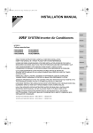
00_CV_3P086156-10X.fm Page 1 Monday, April 13, 2009 4:46 PM
INSTALLATION MANUAL
English
SYSTEM Inverter Air Conditioners
Deutsch
MODELS
(Ceiling suspended Cassette type)
FXUQ71MV1
FXUQ100MV1
FXUQ125MV1
FXUQ71MAV1
FXUQ100MAV1
FXUQ125MAV1
Français
Español
Italiano
ΕλληνικÜ
READ THESE INSTRUCTIONS CAREFULLY BEFORE INSTALLATION.
KEEP THIS MANUAL IN A HANDY PLACE FOR FUTURE REFERENCE.
LESEN SIE DIESE ANWEISUNGEN VOR DER INSTALLATION SORGFÄLTIG DURCH.
BEWAHREN SIE DIESE ANLEITUNG FÜR SPÄTERE BEZUGNAHME GRIFFBEREIT AUF.
LIRE SOIGNEUSEMENT CES INSTRUCTIONS AVANT L’INSTALLATION.
CONSERVER CE MANUEL A PORTEE DE MAIN POUR REFERENCE ULTERIEURE.
LEA CUIDADOSAMENTE ESTAS INSTRUCCIONES ANTES DE INSTALAR.
GUARDE ESTE MANUAL EN UN LUGAR A MANO PARA LEER EN CASO DE TENER
ALGUNA DUDA.
PRIMA DELL’INSTALLAZIONE LEGGERE ATTENTAMENTE QUESTE ISTRUZIONI.
TENERE QUESTO MANUALE A PORTATA DI MANO PER RIFERIMENTI FUTURI.
ÄΙΑΒΑΣΤΕ ΠΡΟΣΕΚΤΙΚΑ ΑΥΤΕΣ ΤΙΣ ΟÄΗΓΙΕΣ ΠΡΙΝ ΑΠΟ ΤΗΝ ΕΓΚΑΤΑΣΤΑΣΗ ΕΧΕΤΕ ΑΥΤΟ
ΤΟ ΕΓΧΕΙΡΙÄΙΟ ΕΥΚΑΙΡΟ ΓΙΑ ΝΑ ΤΟ ΣΥΜΒΟΥΛΕΥΕΣΤΕ ΣΤΟ ΜΕΛΛΟΝ.
LEES DEZE INSTRUCTIES ZORGVULDIG DOOR VOOR INSTALLATIE. BEWAAR DEZE HANDLEINDING WAAR U HEM KUNT TERUGVINDEN VOOR LATERE NASLAG.
LEIA COM ATENÇÃO ESTAS INSTRUÇÕES ANTES DE REALIZAR A INSTALAÇÃO.
MANTENHA ESTE MANUAL AO SEU ALCANCE PARA FUTURAS CONSULTAS.
ПЕРЕД НАЧАЛОМ МОНТАЖА ВНИМАТЕЛЬНО ОЗНАКОМЬТЕСЬ С ДАННЫМИ
ИНСТРУКЦИЯМИ. СОХРАНИТЕ ДАННОЕ РУКОВОДСТВО В МЕСТЕ, УДОБНОМ ДЛЯ
ОБРАЩЕНИЯ В БУДУЩЕМ.
Nederlands
Portugues
Рóссêий
EN60335-2-40,
FXZQ20MVE, FXZQ25MVE, FXZQ32MVE, FXZQ40MVE, FXZQ50MVE
FXCQ20MVE, FXCQ25MVE, FXCQ32MVE, FXCQ40MVE, FXCQ50MVE, FXCQ63MVE, FXCQ80MVE, FXCQ125MVE
FXMQ40MVE, FXMQ50MVE, FXMQ63MVE, FXMQ80MVE, FXMQ100MVE, FXMQ125MVE, FXMQ200MVE, FXMQ250MVE
FXLQ20MVE, FXLQ25MVE, FXLQ32MVE, FXLQ40MVE, FXLQ50MVE, FXLQ63MVE
FXNQ20MVE, FXNQ25MVE, FXNQ32MVE, FXNQ40MVE, FXNQ50MVE, FXNQ63MVE
FXHQ32MVE, FXHQ63MVE, FXHQ100MVE
FXSQ20MVE, FXSQ25MVE, FXSQ32MVE, FXSQ40MVE, FXSQ50MVE, FXSQ63MVE, FXSQ80MVE, FXSQ100MVE, FXSQ125MVE
DAIKIN INDUSTRIES, LTD.
Shinri Sada
Manager Quality Control Department
1st of May 2009
Low Voltage 2006/95/EC
Machinery Safety 98/37/EC
Electromagnetic Compatibility 2004/108/EC
FXKQ25MVE, FXKQ32MVE, FXKQ40MVE, FXKQ63MVE
FXAQ20MVE, FXAQ25MVE, FXAQ32MVE, FXAQ40MVE, FXAQ50MVE, FXAQ63MVE
FXUQ71MV1, FXUQ100MV1, FXUQ125MV1
BEVQ71MVE, BEVQ100MVE, BEVQ125MVE
FXMQ125MFV1, FXMQ200MFV1, FXMQ250MFV1
FXAQ20MHV1, FXAQ25MHV1, FXAQ32MHV1, FXAQ40MHV1, FXAQ50MHV1
BEVQ50MVE
0305020101
TÜV Rheinlard EPS B.V.
DAIKIN.TCF.022E1/10-2007
FXHQ32MAVE, FXHQ63MAVE, FXHQ100MAVE
FXKQ25MAVE, FXKQ32MAVE, FXKQ40MAVE, FXKQ63MAVE
FXAQ20MAVE, FXAQ25MAVE, FXAQ32MAVE, FXAQ40MAVE
FXAQ50MAVE, FXAQ63MAVE
FXUQ71MAV1, FXUQ100MAV1, FXUQ125MAV1
BEVQ71MAVE, BEVQ100MAVE, BEVQ125MAVE
Umeda Center Bldg., 2-4-12, Nakazaki-Nishi,
Kita-ku, Osaka, 530-8323 Japan
FXLQ20MHV1, FXLQ25MHV1, FXLQ32MHV1, FXLQ40MHV1, FXLQ50MHV1,
FXMQ40MAVE, FXMQ50MAVE, FXMQ63MAVE, FXMQ80MAVE
FXMQ100MAVE, FXMQ125MAVE, FXMQ200MAVE, FXMQ250MAVE
FXLQ20MAVE, FXLQ25MAVE, FXLQ32MAVE, FXLQ40MAVE
FXLQ50MAVE, FXLQ63MAVE
FXNQ20MAVE, FXNQ25MAVE, FXNQ32MAVE, FXNQ40MAVE
FXNQ50MAVE, FXNQ63MAVE
3P109591-1E.fm Page 1 Saturday, April 18, 2009 10:25 AM
3P109591-1E
01_EN_3P086156-10X.fm Page 1 Wednesday, April 15, 2009 3:48 PM
FXUQ71MV1
FXUQ100MV1
FXUQ125MV1
FXUQ71MAV1
FXUQ100MAV1
FXUQ125MAV1
VRV SYSTEM Inverter Air Conditioners
CONTENTS
1. SAFETY PRECAUTIONS............................................... 1
2. BEFORE INSTALLATION .............................................. 2
3. SELECTING INSTALLATION SITE AND AIR FLOW
DIRECTION ..................................................................... 3
4. PREPARATIONS BEFORE INSTALLATION ................. 4
5. INDOOR UNIT INSTALLATION ..................................... 7
6. REFRIGERANT PIPING WORK .................................... 8
7. DRAIN PIPING WORK ................................................... 9
8. ELECTRIC WIRING WORK ......................................... 11
9. INSTALLATION OF CORNER COVER AND AIR
INTAKE GRILLE............................................................ 13
10. FIELD SETTINGS ........................................................ 14
11. TEST OPERATION ...................................................... 14
1.
SAFETY PRECAUTIONS
Please read these “SAFETY PRECAUTIONS” carefully before
installing air conditioning unit and be sure to install it correctly.
After completing installation, conduct a trial operation to check
for faults and explain to the customer how to operate the air conditioner and take care of it with the aid of the operation manual.
Ask the customer to store the installation manual along with the
operation manual for future reference.
This air conditioner comes under the term “appliances not
accessible to the general public”.
Safety Precaution
This unit is a class A product. In a domestic environment this
product may cause radio interference in which case the user
may be required to take adequate measures.
Meaning of WARNING and CAUTION notices
WARNING........Failure to follow these instructions properly may result in personal injury or loss
of life.
CAUTION.........Failure to observe these instructions
properly may result in property damage
or personal injury, which may be serious
depending on the circumstances.
WARNING
• Ask your dealer or qualified personnel to carry out installation
work.
Do not attempt to install the air conditioner yourself. Improper
installation may result in water leakage, electric shocks or
fire.
• Install the air conditioner in accordance with the instructions
in this installation manual.
Improper installation may result in water leakage, electric
shocks or fire.
• Consult your local dealer regarding what to do in case of
refrigerant leakage. When the air conditioner is to be
installed in a small room, it is necessary to take proper measures so that the amount of any leaked refrigerant does not
exceed the concentration limit in the event of a leakage.
Otherwise, this may lead to an accident due to oxygen
depletion.
• Be sure to use only the specified accessories and parts for
installation work.
Failure to use the specified parts may result in the unit falling, water leakage, electric shocks or fire.
English
Installation manual
• Install the air conditioner on a foundation strong enough to
withstand the weight of the unit.
A foundation of insufficient strength may result in the equipment falling and causing injury.
• Carry out the specified installation work after taking into
account strong winds, typhoons or earthquakes.
Failure to do so during installation work may result in the unit
falling and causing accidents.
• Make sure that a separate power supply circuit is provided
for this unit and that all electrical work is carried out by qualified personnel according to local laws and regulations and
this installation manual.
An insufficient power supply capacity or improper electrical
construction may lead to electric shocks or fire.
• Make sure that all wiring is secured, the specified wires are
used, and that there is no strain on the terminal connections
or wires.
Improper connections or securing of wires may result in
abnormal heat build-up or fire.
• When wiring the power supply and connecting the remote
controller wiring and transmission wiring, position the wires
so that the control box lid can be securely fastened.
Improper positioning of the control box lid may result in electric shocks, fire or the terminals overheating.
• If refrigerant gas leaks during installation, ventilate the area
immediately.
Toxic gas may be produced if the refrigerant comes into contact with fire.
• After completing installation, check for refrigerant gas leakage.
Toxic gas may be produced if the refrigerant gas leaks into the
room and comes into contact with a source of fire, such as a
fan heater, stove or cooker.
• Be sure to switch off the unit before touching any electrical
parts.
• Do not directly touch the refrigerant leaked from refrigerant
piping connections.
Frostbite may be caused.
• Be sure to earth the air conditioner.
Do not earth the unit to a utility pipe, lightning conductor or
telephone earth lead. Imperfect earthing may result in electric shocks or fire.
A high surge current from lightning or other sources may
cause damage to the air conditioner.
• Be sure to install an earth leakage breaker.
Failure to install an earth leakage breaker may result in electric shocks or fire.
CAUTION
• While following the instructions in this installation manual,
install drain piping to ensure proper drainage and insulate
piping to prevent condensation.
Improper drain piping may result in indoor water leakage
and property damage.
• Install the indoor and outdoor units, power cord and connecting wires at least 1 meter away from televisions or
radios to prevent picture interference and noise.
(Depending on the incoming signal strength, a distance of
1 meter may not be sufficient to eliminate noise.)
• Remote controller (wireless kit) transmitting distance can be
shorter than expected in rooms with electronic fluorescent
lamps (inverter or rapid start types).
Install the indoor unit as far away from fluorescent lamps as
possible.
1
01_EN_3P086156-10X.fm Page 2 Wednesday, April 15, 2009 3:48 PM
• Do not install the air conditioner in the following locations:
1. Where there is a high concentration of mineral oil spray or
vapour (e.g. a kitchen).
Plastic parts will deteriorate, parts may fall off and water
leakage could result.
2. Where corrosive gas, such as sulphurous acid gas, is produced.
Corroding of copper pipes or soldered parts may result in
refrigerant leakage.
3. Near machinery emitting electromagnetic radiation.
Electromagnetic radiation may disturb the operation of the
control system and result in a malfunction of the unit.
4. Where flammable gas may leak, where there is carbon
fibre or ignitable dust suspensions in the air, or where volatile flammables such as paint thinner or gasoline are
handled.
Operating the unit in such conditions may result in fire.
• The air conditioner is not intended for use in a potentially
explosive atmosphere.
2-2
ACCESSORIES
Check the following accessories are included with the unit.
Name
1) Drain hose
2) Metal clamp
Quantity
1 pc.
1 pc.
3) Washers for
locking hanger
8 pcs.
Shape
Name
4) Clamp
Quantity
6 pcs.
5) Washer fixing
plate
4 pcs.
Insulation for
fitting
1 each
6) For gas piping
Shape
7) For liquid piping
2.
BEFORE INSTALLATION
When moving the unit after removing it from the box,
remove the corner covers and use the 4 hoisting hooks to
move it. Do not apply force to the refrigerant piping, drain
piping or resin parts.
• When moving the unit while removing it from the box, be
sure to lift it by holding on to the four lifting lugs without
exerting any pressure on other parts, especially swing flap,
the refrigerant piping, drain piping, and other resin parts.
• Be sure to check the type of R410A refrigerant to be used
before installing the unit. (Using an incorrect refrigerant will
prevent normal operation of the unit.)
• Decide upon a line of transport.
• Leave the unit inside its packaging while moving, until
reaching the installation site. Use a sling of soft material,
where unpacking is unavoidable or protective plates
together with a rope when lifting, to avoid damage or
scratches to the unit.
• Refer to the installation manual of the outdoor unit for items
not described in this manual.
• A separate BEV unit is required for this model.
See the installation manual that comes with the BEV unit
when doing the installation.
• Installation should only be carried out after checking in
advance the type of refrigerant to be used. (Using the wrong
refrigerant will prevent the unit from functioning properly.)
• Do not dispose of any parts necessary for installation until
the installation is complete.
2-1
PRECAUTIONS
• Be sure to read this manual before installing the indoor unit.
• When selecting installation site, refer to the paper pattern.
• This unit is suitable for installation in a household, commercial and light industrial environment.
• Do not install or operate the unit in rooms mentioned below.
• Laden with mineral oil, or filled with oil vapor or spray like
in kitchens. (Plastic parts may deteriorate.)
• Where corrosive gas like sulfurous gas exists. (Copper
tubing and brazed spots may corrode.)
• Where volatile flammable gas like thinner or gasoline is
used.
• Where machines can generate electromagnetic waves.
(Control system may malfunction.)
• Where the air contains high levels of salt such as that near
the ocean and where voltage fluctuates greatly such as
that in factories. Also in vehicles or vessels.
2
Name
Quantity
Shape
Sealing pad
10) Elbow
2 pcs.
8) Large
1 pc.
11) Paper pattern
for installation
1 pc.
Also used as
packing material
9) Small
Name
12) Blocking pad
Quantity
2 pcs.
13) Retainer for
blocking pad
2 pcs.
14)Retainer for
blocking pad
2 pcs.
Shape
15) Center retainer
for blocking pad
Quantity
2 pcs.
Name
Shape
2-3
(Other)
• Operation manual
• Installation manual
OPTIONAL ACCESSORIES
• The remote controller are required for this indoor unit.
• These are two types of remote controllers: wired and wireless. Select a remote controller from Table 1 according to
customer request and install in an appropriate place.
(For installation, follow the Installation manual included with
the remote controllers.)
Table 1
Remote controller
Wired type
Wireless type
Heat pump type
Cooling only type
NOTE
• If you wish to use a remote controller that is not listed in
Table 1, select a suitable remote controller after consulting
catalogs and technical materials.
English
01_EN_3P086156-10X.fm Page 3 Wednesday, April 15, 2009 3:48 PM
[PRECAUTION]
If installing the wireless kit in a room with electronic fluorescent
lighting (inverter or rapid start type), the remote controller’s
transmission distance may be shortened. Indoor units should
be installed as far away from fluorescent lighting as possible.
• Install the indoor and outdoor units, power supply wiring and
connecting wiring at least 1 meter away from televisions or
radios in order to prevent image interference or noise.
(Depending on the radio waves, a distance of 1 meter may
not be sufficient enough to eliminate the noise.)
[CAUTION]
Only use the included parts or parts which match the specifications when installing the unit.
• Install the indoor unit no less than 2.5m above the floor.
Where unavoidably lower, take what measures are necessary to keep hands out of the air outlet.
Space required for installation
2. Items to be checked at time of delivery
Items to be checked
Check
Did you explain about operations while showing the
operation manual to your customer?
Did you hand the operation manual over to your customer?
Air discharge
For installation
in high places.
The items with
WARNING and
CAUTION marks in
the operation manual are the items pertaining to possibilities for bodily injury and material damage in addition
to the general usage of the product. Accordingly, it is
necessary that you make a full explanation about the
described contents and also ask your customers to read
the operation manual.
NOTE TO THE INSTALLER
3.
SELECTING INSTALLATION SITE AND
AIR FLOW DIRECTION
3-1
Select an installation site where the following
conditions are fulfilled and that meets your
customer’s approval.
• In the upper space (including the back of the ceiling) of the
indoor unit where there is no possible dripping of water from
the refrigerant piping, drain piping, water pipinge, etc.
• Where optimum air distribution can be ensured.
English
≥ 1500
Obstruction
Floor
3. Points for explanation about operations
Be sure to instruct customers how to properly operate the unit
(especially cleaning filters, operating different functions, and
adjusting the temperature) by having them carry out operations
themselves while looking at the manual.
≥ 1500
Air inlet
≥ 1000
∗Also review the “SAFETY PRECAUTIONS”
2-4
Air discharge
Air discharge
≥ 1500
Floor
Air inlet
Obstruction
≥ 1000
Check
≥ 2500
If not properly done, what
is likely to occur
Are the indoor and outThe unit may drop,
door unit fixed firmly?
vibrate or make noise.
Is the gas leak test finIt may result in insufficient
ished?
cooling.
Is the unit fully insulated? Condensate may drip.
Does drainage flow
Condensate may drip.
smoothly?
The unit may malfunction
Does the power supply
voltage correspond to that or the components burn
shown on the name plate? out.
The unit may malfunction
Are wiring and piping coror the components burn
rect?
out.
Is the unit safely
Risk of electric shock at
grounded?
electric leakage.
The unit may malfunction
Is wiring size according to
or the components burn
specifications?
out.
Is something blocking the
air outlet or inlet of either It may result in insufficient
the indoor or outdoor
cooling.
units?
Are refrigerant piping
length and additional
The refrigerant charge in
refrigerant charge noted the system is not clear.
down?
Items to be checked
≥ 2500
1. Items to be checked after completion of work
• Where nothing blocks air passage.
• Where condensate can be properly drained.
• Where the ceiling is strong enough to bear the indoor unit
weight.
• Where the false ceiling is not noticeably on an incline.
• Where sufficient clearance for maintenance and service can
be ensured.
• Where there is no risk of flammable gas leakage.
• Where piping between indoor and outdoor units is possible
within the allowable limit.
(Refer to the installation manual for the outdoor and BEV units.)
For installation
in high places.
FOR THE FOLLOWING ITEMS, TAKE SPECIAL CARE
DURING CONSTRUCTION AND CHECK AFTER
INSTALLATION IS FINISHED.
≥ 30∗∗
(length: mm)
∗∗ Space is required to attach/detach corner covers.
3-2
Air flow direction
Select the air flow direction that best suits the unit’s location.
2-way and 3-way air flow must be set from the remote controller. For details, see “10. FIELD SETTINGS”.
NOTE
• Restrictions are placed on piping direction, therefore select
flow direction from the below patterns.
[Air flow patterns] (Refer to Fig. 1)
(IIlustrations seen from ceiling)
A, B, C and D indicate drain pans.
3
01_EN_3P086156-10X.fm Page 4 Wednesday, April 15, 2009 3:48 PM
Air flow
direction
C
D
B
D
B
Ceiling slab
D
C
C
A
4-way air
discharge
3-way air
3-way air
discharge
discharge
Optional parts required
(Back-to-back blocking pad kit)
C
C
False ceiling
Long nut or turnbuckle
Suspension bolt
Fig. 3
(length: mm)
NOTE
• All the above parts are field supplied.
D
A
2-way air
discharge
2-way air
discharge
Fig. 1
Refrigerant piping direction
To the rear (Straight piping)
To the right (Elbow required)
Upward running refrigerant piping are possible in all patterns.
3-3
50-100
Anchor
A
Use suspension bolts for installation. Check
whether the ceiling is strong enough to support
the weight of the unit or not. If there is a risk,
reinforce the ceiling before installing the unit.
(Installation pitch is marked on the paper pattern for installation. Refer to it to check for points requiring reinforcing.)
4.
PREPARATIONS BEFORE
INSTALLATION
4-1
FOR 4-WAY AIR DISCHARGE
(Use either a M8-M10 size bolt)
Use a hole-in anchor for existing ceilings, and a sunken insert,
sunken anchor or other field supplied parts for new ceilings to
reinforce the ceiling to bear the weight of the unit. Adjust clearance from the false ceiling before proceeding further.
3. Detach the air intake grille and corner covers from the
indoor unit.
• Detach the air intake grille. (Refer to Fig. 4 and 5)
• Slide the locking knobs (×2) on the air intake grille inward
(direction of arrows) and lift upwards.
• Open the air intake grille to a 45° angle and detach from
the unit.
• Detach the corner covers.
Air intake
grille
Cornercover (×4)
1. Relation of holes for indoor unit, suspension bolt position, piping and wiring. (Refer to Fig. 2)
(Illustrations seen from ceiling)
Fig. 4
Hold the indoor unit by the
hanger brackets when carrying.
895
790∗∗∗
B
30
D
790∗∗∗
895
C
180
83
Fig. 5
33
A
163
Upward running drain
piping shown above
∗ 40 (107)
∗ 58 (125)
∗ 80 (147)
Drain hose connection (VP20)
Shutter
Liquid piping
Gas piping
Fig. 2
(length: mm)
∗ Dimensions in ( ) for 100 and 125 models
∗∗∗ Suspension bolt pitch
2. Make holes for suspension bolts, refrigerant and drain
piping, and wiring. (Refer to Fig. 3)
• Refer to the paper patten for the locations.
• Select the location for each of holes and open the holes in
the ceiling.
4
[TO CHANGE AIR FLOW RATE]
• When shipped from the factory, the shutters on air outlets C
and D are closed so that air flow rate is the same in all four
directions.
• Air flow rate can be changed by sliding the shutter.
(Refer to Fig. 6 and 7)
Fig. 6
CAUTION
Be careful not to touch the heat exchanger fins.
English
01_EN_3P086156-10X.fm Page 5 Wednesday, April 15, 2009 3:48 PM
NOTE
• IIlustration seen from ceiling
895
790∗∗∗
C
B
180
Air discharge
Shutter (Indicates drain pan.)
C
D
B
Ceiling slab
Moderate
flow rate
B
D
False ceiling
Long nut or turnbuckle
(length: mm)
NOTE
• To change air flow rate, select a pattern from “TO CHANGE
AIR FLOW RATE” and determine the location of piping.
• All the above parts are field supplied.
C
B
D
Moderate
flow rate
Fig. 7
[CEILING HEIGHT]
The indoor unit may be installed on ceilings up to 3.5m in height.
However, it becomes necessary to make field settings by remote
controller when installing the unit at a height over 2.7m.
Refer to the section entitled “10. FIELD SETTINGS” .
Install this unit where the height of bottom panel is more than
2.5m so that user cannot easily touch.
FOR 2-WAY OR 3-WAY AIR DISCHARGE
2-way and 3-way air discharge must be set from the remote
controller. For details, see “10. FIELD SETTINGS”.
1. Relation of holes for indoor unit, suspension bolt position, piping and wiring. (Refer to Fig. 8)
English
Anchor
Suspension bolt
Fig. 9
A
A
(length: mm)
D
C
Moderate
flow rate
Drain hose
connection (VP20)
2. Make holes for suspension bolts, refrigerant and drain
piping, and wiring. (Refer to Fig. 9)
• Refer to paper pattern for the locations.
• Select the location for each of holes and open the holes in
the ceiling.
C
A
Moderate flow rate
Moderate
flow rate
Liquid piping
Gas piping
NOTE
• Illustrations seen from ceiling
∗ Dimension in ( ) for 100 and 125models
∗∗∗ Suspension bolt pitch
A
B
Rightward running drain
piping shown above
117
Fig. 8
50-100
Moderate
flow rate
Moderate
flow rate
∗ 40 (107)
Moderate
flow rate
∗ 58 (125)
C
∗ 80 (147)
D
Piping area A
When shipped from factory
4-2
A
33
B
83
A
Piping area
D
30
Shutter
790∗∗∗
D
B
895
C
(Use either a M8-M10 size bolt.)
Use a hole-in anchor for existing ceilings, and a sunken
insert, sunken anchor or other field supplied parts for new
ceilings to reinforce the ceiling to bear the weight of the unit.
Adjust clearance from the false ceiling before proceeding
further.
3. Detach the air intake grille and corner covers from the
indoor unit.
• Detach the air intake grille. (Refer to Fig. 10)
• Slide the locking knobs (×2) on the air intake grille inward
(direction of arrows) and lift upwards.
• Open the air intake grille to a 45° angle and detach from
the unit.
• Detach the corner covers.
5
01_EN_3P086156-10X.fm Page 6 Wednesday, April 15, 2009 3:48 PM
4. After installing the blocking pads, attach the center retainer for
blocking pad and the top decorative plate. (Refer to Fig. 13)
Air intake
grille
Cornercover (×4)
Fig. 10
Hold the indoor unit by the
hanger brackets when carrying.
Center retainer
for blocking pad (15)
(accessory)
Screw for top
decorative plate
Insert
here.
Top decorative
plate
Insert
here.
Center retainer for
blocking pad (15)
(accessory)
Bottom decorative plate
[THE WAY TO BLOCK AIR DISCHARGE OUTLETS]
Blocking pad
For 2-way air discharge, outlets A and B must be blocked.
For 3-way air discharge, outlets A or B must be blocked.
1. Detach the top decorative plate from the outlets to be
blocked. (Refer to Fig. 11)
Top decorative
plate
Fig. 13
CAUTION
Unless blocking pads are installed as indicated, air will leak
and consequently cause dewing.
Bottom
decorative plate
Flap
Top decorative plate
Screw for top
decorative plate
Fig. 11
2. Detach the flap from the outlets, too.
3. Attach the retainers to the blocking pad. (Refer to Fig. 12)
Align the projections on the pads with the holes on the
retainers, and tape parts together with 2-sided tape.
Retainers for
blocking pad (13)(14)
(accessory)
[TO CHANGE AIR FLOW RATE]
• When shipped from the factory,
the shutters on air discharge outlets C and D are closed so that
air flow rate is the same in all four
directions.
• Air flow rate can be changed by
sliding the shutter.
(Refer to Fig. 14)
Fig. 14
CAUTION
Be careful not to touch the heat exchanger fins.
2-way air discharge (Refer to Fig. 15)
NOTE
• Illustrations seen from ceiling
Blocking pad (12)
(accessory)
Projection
C
Hole
Fig. 12
Shutter
B
2-sided tape
D
Shutter
Piping
area
A
Air discharge
(Indicates drain pan.)
Blocking pad
C
B
Piping
area
6
A
D
Shutter
English
01_EN_3P086156-10X.fm Page 7 Wednesday, April 15, 2009 3:48 PM
Moderate flow rate
C
C
B
Moderate
flow rate
D
A
A
Blocking pad
D
B
C
Moderate
flow rate
Moderate
flow rate
C
B
B
A
Blocking pad
A
D
D
C
C
B
Moderate
flow rate
B
D
D
A
Blocking pad
B
A
Blocking pad
A
C
D
5.
A
B
Shutter
C
English
Blocking pad
D
Shutter
INDOOR UNIT INSTALLATION
<<Installing optional accessories before installing the
indoor unit is easier. >>
As for the parts to be used for installation work, be sure to use
the provided accessories and specified parts designated by
our company.
5-1
A
D
[CEILING HEIGHT]
The indoor unit may be installed on ceilings up to 3.8 m in height.
However, it becomes necessary to make field settings by remote
controller when the height of the ceiling is over 3m in three directions or over 3.5m in two directions. Refer to the section entitled
“10. FIELD SETTINGS” and the decoration panel installation
manual.
Install this unit where the height of bottom panel is more than
2.5m so that user cannot easily touch.
3-way air discharge (Refer to Fig. 16)
B
A
Moderate flow rate
Fig. 16
Moderate
flow rate
Fig. 15
Piping
area
C
C
D
Piping
area
Moderate
flow rate
Fit the top nuts and washers over the
suspension bolts (×4).
• Use the washer fixing plate (5) to keep the washer from falling out of place. Hang the unit from the hangers on side A,
and then fit the bottom washers and nuts over the suspension bolts on that side. (Refer to Fig. 17)
7
01_EN_3P086156-10X.fm Page 8 Wednesday, April 15, 2009 3:48 PM
Securing the washer
Piping area
A
B
D
5-2
C
Fig. 17
Insert below
washer.
Washer fixing plate (5)
(accessory)
Install the indoor unit. (Refer to Fig. 18)
• Lock the unit to the hangers on side A.
• Hook the unit onto the other 2 hangers and lock with bottom
washers and nuts.
CAUTION
• Use a pipe cutter and flare suitable for the type of refrigerant.
• Apply ester oil or ether oil around the flare section
before connecting.
• To prevent dust, moisture or other foreign matter from
infiltrating the tube, either pinch the end or cover it with
tape.
• Do not allow anything other than the designated refrigerant to get mixed into the refrigerant circuit, such as
air, etc. If any refrigerant gas leaks while working on the
unit, ventilate the room thoroughly right away.
6-1
Refrigerant piping can be run in 3 directions
(Refer to Fig. 20)
Hanger bracket
Nut (Field supplied)
Upward running piping
Washers for locking
Tighten
hanger (3) (accessory)
(double nuts.)
Fig. 18
5-3
Check whether the unit is level from sides C
and D both. (Refer to Fig. 19)
Level check
A
D
Fig. 19
5-4
Rearward running piping
Piping area
B
C
Rightward running piping
Fig. 20
Level
Remove the washer fixing plate (5) used for
preventing the washer from falling and tighten
the upper nut.
CAUTION
• Do not hold the swing flap when mounting, as this may
break it.
• The indoor unit is equipped with a built-in drain pump and
float switch. At each of the unit’s 4 corners, verify that it is
level by using a water level or a waterfilled vinyl tube.
(If the unit is tilted against condensate flow, the float switch
may malfunction and cause water to drip.)
• Use copper alloy seamless piping (ISO 1337).
• The outdoor unit is charged with refrigerant.
• Be sure to use both a spanner and torque wrench together,
when connecting or disconnecting piping to/from the unit.
(Refer to Fig. 21)
• Refer to the Table 2 for flare dimensions and tightening torque.
Torque wrench
Spanner
Piping union
Flare nut
6.
REFRIGERANT PIPING WORK
〈For refrigerant piping of outdoor and BEV units, see the
installation manual attached to the outdoor and BEV units.〉
〈Execute heat insulation work completely on both sides of
the gas piping and the liquid piping.
Otherwise, a water leakage can result sometimes.〉
〈When using a heat pump, the temperature of the gas piping can reach up to approximately 120°C, so use insulation
which is sufficiently resistant.〉
〈Improve the insulation on the refrigerant piping depending on the installation environment.
If the insulation is not sufficient, condensation may form
on the surface of the insulation.〉
〈Before refrigerant piping work, check which type of refrigerant is used. Proper operation is not possible if the types
of refrigerant are not the same.〉
8
Fig. 21
NOTE
• Use the flare nut included with the unit main body.
CAUTION
• Over-tightening the flare nut may break it and/or cause the
refrigerant to leak.
• When connecting the flare nut,
apply ester oil or ether oil to
the flare section (both inside
and outside), and spin 3-4
times before screwing in.
(Refer to Fig. 22 )
Ester oil or ether oil
Fig. 22
English
01_EN_3P086156-10X.fm Page 9 Wednesday, April 15, 2009 3:48 PM
Table 2
φ9.5(3/8”)
32.7-39.9 N • m
12.8 – 13.2
φ15.9(5/8”)
61.8-75.4 N • m
19.3 – 19.7
Flare
45˚±2˚
Flare
dimensions A (mm)
R0.4-0.8
A
Tightening torque
90˚±2˚
Pipe size
• Refer to “Table 2” to determine the proper tightening torque.
Not recommendable but in case of emergency
You must use a torque wrench but if you are obliged to install
the unit without a torque wrench, you may follow the installation
method mentioned below.
When you keep on tightening the flare nut with a spanner, there
is a point where the tightening torque suddenly increases.
From that position, further tighten the flare nut the angle shown
below:
Table 3
Pipe size
Further tightening angle
φ9.5 (3/8”)
φ15.9 (5/8”)
60 to 90 degrees
30 to 60 degrees
Recommended arm
length of tool
Approx. 200mm
Approx. 300mm
After the work is finished, make sure to check that there is
no gas leak.
• Make absolutely sure to execute heat insulation works on
the pipe-connecting section after checking gas leakage by
thoroughly studying the following figure and using the
attached insulation for fitting (6) and (7). (Fasten both ends
with the clamps (4).) (Refer to Fig. 23)
• Wrap the sealing pad (9) only around the insulation for the
joints on the gas piping side.
Attach to tha root
Insulation for gas
piping (6)
(accessory)
Small sealing
pad (9)
(accessory)
• Before brazing local refrigerant piping, nitrogen gas shall be
blown through the piping to expel air from the piping.
If you brazing is done without nitrogen gas blowing, a large
amount of oxide film develops inside the piping, and could
cause system malfunction.
• When brazing the refrigerant piping, only begin brazing after
having carried out nitrogen substitution or while inserting
nitrogen into the refrigerant piping. Once this is done, connect the indoor unit with a flared connection.
• Nitrogen should be set to 0.02 MPa with a pressure-reducing valve if brazing while inserting nitrogen into the piping.
(Refer to Fig. 25)
Pressure-reducing valve
Refrigerant piping
Part to be
brazed
Taping
hands valve
Nitrogen
Nitrogen
Fig. 25
CAUTION
Do not use anti-oxidants when brazing the piping joints.
Residue can clog piping and break equipment.
Clamp (4)
(×4)
(accessory) Fig. 23
For upward and rightward running piping
• Upward and rightward running piping are easily rigged with
the optional connecting elbow kit.
• For upward running piping, detach the pipe hole cover.
• Once piping are rigged, cut the pipe hole cover to size and
reattach. Use scissors for cutting.(Refer to Fig. 24)
Pipe hole cover
CAUTION
CAUTION TO BE TAKEN WHEN BRAZING REFRIGERANT
PIPING
“Do not use flux when brazing refrigerant piping. Therefore, use
the phosphor copper brazing filler metal (BCuP-2:JIS Z 3264/BCu93P-710/795:ISO 3677) which does not require flux.”
(Flux has extremely harmful influence on refrigerant piping systems. For instance, if the chlorine based flux is used, it will
cause piping corrosion or, in particular, if the flux contains fluorine, it will damage the refrigerant oil.)
Insulation for liquid
piping (7) (accessory)
CAUTION
For local insulation, be sure to insulate all the way to the piping
connections inside the unit.
Exposed piping may cause leaking or burns on contact.
6-2
Since there exists a possibility that small animals and
insects might get inside the indoor unit, attach the wiring through covers and make sure there are no gaps in
the through holes by applying putty or insulation (field
supplied).
• When doing this, block any gaps between the piping penetration lid and the piping using putty to prevent dust from
entering the indoor unit.
For liquid piping
For gas piping
7.
DRAIN PIPING WORK
7-1
Rig drain piping (Refer to Fig. 26)
As for drain piping work, perform piping in such a manner that
water can be drained properly.
As for drain piping, the connection can be made from three different directions.
• Employ a pipe with either the same diameter or with the
diameter larger (excluding the raising section) than that of
the connecting piping (PVC pipe, nominal diameter 20mm,
outside diameter 26mm).
• Keep the drain piping short and sloping downwards at a gradient of at least 1/100 to prevent air pockets from forming.
(Refer to Fig. 27)
CAUTION
Water pooling in the drainage piping can cause the drain to clog.
For drain piping
For wiring
Fig. 24
English
9
01_EN_3P086156-10X.fm Page 10 Wednesday, April 15, 2009 3:48 PM
VP20
Drain hose (1) (For VP20 connection)
(accessory)
Ceiling slab
1 - 1.5 m
Hanger
bracket
Elbow (10)
VP20
Large sealing pad (8) (accessory)
Clamp (2) (accessory)
Notes on upward running drain hose
Fig. 26
Rearward running piping
Min. 1/100 gradient
GOOD
Rightward running drain hose
•
•
•
•
•
•
WRONG
Fig. 27
To keep the drain hose from sagging, space hanging wiring
every 1 to 1.5m. (Refer to Fig. 26)
Use only the included drain hose (1), (for rightward running
drain hose) or elbow (10) (for upward running drain hose)
and clamp (2).
Fit the drain hose (1) or elbow (10) over the drain piping up
to the neck and fasten tight with the metal clamp (2).
Tighten the metal clamp (2) unit the screw head is less than
4mm from the hose.
Insulate the metal clamp (2) and drain hose or elbow (10)
with the included sealing pad (8). (Refer to Fig. 28)
Make sure that heat insulation work is executed on the following 2 spots to prevent any possible water leakage due to
dew condensation.
• Insulate the drain hose inside the building
• Drain socket
Metal clamp (2)
Metal clamp (2)
(accessory)
Tape
(accessory)
Drain hose (1)
(accessory)
Large
sealing pad (8)
(accessory)
≤4mm
Fig. 28
CAUTION
• Do not twist or bend the drain hose (1), so that excessive
force is not applied to it, as this could cause leaks.
• If converging multiple drain piping, install according to the
procedure shown below. (Refer to Fig. 29)
Select converging drain piping whose gauge is suitable for
the operating capacity of the unit.
≥100mm
≤500
Drain piping
(field supplied)
T-joint converging drain piping
Fig. 29
PRECAUTIONS FOR UPWARD DRAIN RAISING PIPING
• Install the drain raising piping at a height of less than
500mm.
• Install the drain raising piping at a right angle to the indoor
unit. (Refer to Fig. 30)
WRONG
Metal clamp (2) (accessory)
Fig. 30
Elbow (10)
(accessory)
Long
end
Large sealing pad (8) (accessory)
Metal clamp (2) (accessory)
CAUTION
If the upward running drain hose leans at a slant, the float
switch will malfunction and water will leak.
7-2
• Open the water inlet lid, add approximately 1 liter of water
slowly and check drainage flow. (Refer to Fig. 31)
Inspection opening
Service drain outlet
(with rubber plug).
Service cover
(Use this outlet to drain water
from the drain pan.)
Drain hose (1) (accessory)
Large sealing pad (8) (accessory)
Large sealing pad (8) (accessory)
After piping work is finished, check if drainage
flows smoothly.
≥100
≥100
Elbow (10) (accessory)
Upward
running
piping
Metal clamp (2) (accessory)
Short end
10
Drain piping Adding water from inspection opening
Plastic watering can
(Tube should be about 100 mm long.)
Adding water through air discharge outlet
Method of adding water
Fig. 31
English
01_EN_3P086156-10X.fm Page 11 Wednesday, April 15, 2009 3:48 PM
WHEN ELECTRIC WIRING WORK IS FINISHED
• Check drainage flow during Cooling operation, explained
under “11. TEST OPERATION”.
WHEN ELECTRIC WIRING WORK IS NOT FINISHED
CAUTION
• Electrical wiring work should be done by a certified electrician.
• If someone who does not have the proper qualifications performs the work, perform the following after the test run is
complete.
• Remove the control box lid and change the emergency
switch above the PC board assembly of the indoor unit from
“NORM.” to “EMERG.”. Connect the single-phase power
supply (1, 3) and ground wire to the inter-unit wiring (50Hz
220-240V) terminal block and confirm drain operation.
Be sure to change the switch before turning on the power.
(Refer to Fig. 32)
CAUTION
• Clamp solidly to clamp C to tension is not added to the
wiring connections.
• Be aware that the fan will turn during the operation.
• After confirming drainage, turn off the power and be sure to
change the emergency switch back to “NORM.”.
Inter-unit wiring terminal block
Tab
Clamp C
Indoor PC
board
Clamp C
Emergency switch assembly
Single phase power supply
• Checking the drain
NORM. EMERG.
1 2 3
• After the checking
NORM. EMERG.
Inter-unit
wiring
terminal
block
Fig. 32
8.
ELECTRIC WIRING WORK
8-1
GENERAL INSTRUCTIONS
• All field supplied parts and materials and electric works
must conform to local codes.
• Use copper wire only.
• For electric wiring work, refer also to “WIRING DIAGRAM”
attached to the control box lid.
• For remote controller wiring details, refer to the installation
manual attached to the remote controller.
• All wiring must be performed by an authorized electrician.
• One BEV unit is connected to one indoor unit. Mark each
indoor unit and BEV unit as unit A, unit B..., and be sure the
terminal block wiring to the outdoor unit and BS unit are
properly matched. If wiring and piping between the outdoor
unit and an indoor unit and BEV unit are mismatched, the
system may cause a malfunction.
• A circuit breaker capable of shutting down power supply to
the entire system must be installed.
• Refer to the installation manual attached to the outdoor unit
for the size of power supply wiring connected to the outdoor
unit, the capacity of the circuit breaker and switch, and wiring instructions.
• Be sure to ground the air conditioner
• Do not connect the ground wire to gas and water pipes,
lightning rods, or telephone ground wires.
• Gas pipes: might cause explosions or fire if gas leaks.
• Water pipes: no grounding effect if hard vinyl piping is
used.
• Telephone ground wires or lightning rods: might cause
abnormally high electric potential in the ground during
lighting storms.
• Specifications for field wire
The remote controller wiring should be procured locally. Refer
to the Table 4 when preparing one.
Table 4
Inter-unit wiring
Remote
controller wiring
Wire
H05VV - U4G
(NOTE 1)
Vinyl cord with
sheath or cable
(2 wire) (NOTE 2)
Length
2.5
(NOTE 3)
0.75 - 1.25
Max.
500m
2
NOTE
1. Shows only in case of protected pipes. Use H07RN-F in case
of no protection.
2. Insulated thickness : 1mm or more
3. Refer to the installation manual of the BEV unit.
<Methods of wiring units and connecting remote controller wiring> (Refer to Fig. 33)
NOTE
1. All wiring except for the remote controller wires is polarized
and must match the terminal symbol.
• Wiring the units connections
Remove the control box lid, and align the phases with
those of the power supply terminal block inside to connect. Securely fix the wires with the included clamp material A, then fix them with the clamp material C likewise.
• Remote controller wiring connections
Connect to the remote controller terminal block. (no polarity)
Securely fix the remote controller wiring with the included
clamp material B, then fix it with the clamp material D likewise.
How to connect wiring
Remote controller
wiring
Clamp B
Terminal block for remote
controller (2P)
Tab
Blue
Blue
Clamp C and D
Wiring the units
1 2 3
Clamp A
Ground wire
terminal
How to connect inter-unit wiring
terminal block (4P)
English
Size (mm )
P1 P2
[Caution]
Drain piping connections
• Do not connect the drain piping directly to sewage pipes that
smell of ammonia. The ammonia in the sewage might enter
the indoor unit through the drain piping and corrode the heat
exchanger.
Inter-unit
wiring
terminal
block (4P)
Clamp D
Remote controller
wiring
Power supply wiring
Clamp C
Fig. 33
11
01_EN_3P086156-10X.fm Page 12 Wednesday, April 15, 2009 3:48 PM
•
•
•
•
CAUTION
When clamping wiring, use the included clamping material
to prevent outside pressure being exerted on the wiring connections and clamp firmly. When doing the wiring, make
sure the wiring is neat and does not cause the control box
lid to stick up, then close the cover firmly.
When attaching the control box lid, make sure you do not
pinch any wires.
After all the wiring connections are done, fill in any gaps in
the through holes with putty or insulation (field supplied) to
prevent small animals and insects from entering the unit
from outside. (If any do get in, they could cause short circuits in the control box.)
Outside the unit, separate the weak wiring (remote controller wiring) and strong wiring (inter-unit wiring, ground wire,
and other power wiring) at least 50 mm so that they do not
pass through the same place together. Proximity may cause
electrical interference, malfunctions, and breakage.
8-2
WIRING EXAMPLE
• Fit the power supply wiring of each unit with a switch and
fuse as shown in the drawing.
COMPLETE SYSTEM EXAMPLE (3 systems)
Power supply
wiring
Transmission
wiring
Power supply
Main
switch
Switch
Fuse
BS unit
(Only for Heat
recovery
system)
BEV unit
[PRECAUTIONS]
1. Use round crimp-style terminals for connecting wiring to the
power supply terminal block.
If unavailable, observe the following points when wiring.
• Do not connect wiring of different gauge to the same
power supply terminal.
(Looseness in the connection may cause overheating.)
• Use the specified electric wiring. Connect the wiring
securely to the terminal. Lock the wiring down without
applying excessive force to the terminal. (Tightening
torque: 131N·cm ±10 %)
Indoor unit
Remote controller
1. When using 1 remote controller for 1 indoor unit. (Normal operation)
Power supply Power supply
Outdoor unit
L N
Power supply
L N
L N
Control box
Power supply
L N
IN/D OUT/D
F 1 F 2 F 1 F2
Attach insulation sleeve
TO indoor
L N
Round crimp-style terminal
Electric wiring
Terminal
Size
Tightening torque
Terminal block for remote controller (2P)
M3.5
0.79 – 0.97N·m
Inter-unit wiring and ground wire
terminal block (4P)
12
1 2 3
L N
1 2 3 F1 F2
BEV Unit C
P1 P2
1 2 3
L N P1 P2 F 1 F 2 T 1 T 2
P1 P2
Normal VRV
Indoor Unit A
Indoor Unit B
Indoor Unit C
Indoor Unit
Remote
Remote P P
P P
P P
controller P P
controller
Remote
Remote
Maximum one indoor unit
controller
controller
for each BEV unit.
When calculating the limit of
If the remote controller does not have a
connected indoor units, count all
cooling/heating selection right, “operation
the lower BEV units as one unit.
switch is being managed” will be displayed.
1
1
2
1
2
1
2
2
2. For group control or use with 2 remote controllers
Power supply
Outdoor unit
Control box
1.18 – 1.44N·m
3. Do not connect wiring of different gauge to the same grounding terminal. Looseness in the connection may deteriorate
protection.
4. Outside of the unit, keep remote controller wiring at least
50 mm away from power supply wiring. The unit may malfunction if subjected to electrical (external) noise.
5. For remote controller wiring, refer to the “INSTALLATION
MANUAL OF REMOTE CONTROLLER” attached to the
remote controller.
6. Never connect power supply wiring to the terminal block
for remote controller wiring. A mistake of the sort could
damage the entire system.
7. Use only specified wiring and tightly connect wiring to terminals. Be careful wiring do not place external stress on terminals. Keep wiring in neat order and so as not to obstruct other
unit such as popping open the control box lid. Make sure the
lid closes tight. Incomplete connections could result in overheating, and in worse case, electric shock or fire.
TO indoor
1 2 3 F1 F2
BEV Unit B
P1 P 2
L N
M4
L N
BEV Unit A
1 2 3
2. Tightening torque for the terminal screws.
• Use the correct screwdriver for tightening the terminal
screws. If the blade of screwdriver is too small, the head
of the screw might be damaged, and the screw will not be
properly tightened.
• If the terminal screws are tightened too hard, screws
might be damaged.
• Refer to the table below for the tightening torque of the
terminal screws.
TO indoor
1 2 3 F1 F2
IN/D OUT/D
F 1 F2 F1 F2
BEV unit B
BEV unit A
LN
1 2 3
F 1 F2
1 2 3
P 1 P2
LN
1 2 3
F 1 F2
1 2 3
P1 P2
LN
1 2 3
F 1 F2
1 2 3
P1 P2
Indoor unit B
Indoor unit A
P1 P2
For use with 2
remote controllers
P1 P 2
Most
downstream
BEV unit
Most
downstream
indoor unit
P1 P 2
English
01_EN_3P086156-10X.fm Page 13 Wednesday, April 15, 2009 3:48 PM
<Caution>
• If using group control and two remote controllers at the
same time, connect remote controller 2 (SUB) to the indoor
unit which is at the end of the crossover wiring (P1, P2). (See
the figure below.)
• Group control is not possible between ceiling suspended
cassette type units and normal VRV indoor units.
3. When including BS unit
Power supply
Power supply
Outdoor unit
L N
L N
Control box
IN/D OUT/D
F1 F2 F1 F2
L N
F1 F2 F1 F2
OUT/D,
BS
L N
F1 F2 F1 F2
OUT/D,
BS
IN/D
TO indoor
L N
Indoor unit 1
IN/D
Final indoor unit
Crossover
wiring (P1, P2)
Remote
controller 2
(SUB)
TO indoor
1 2 3 F1 F2
BEV Unit A
L N
Remote
controller 1
(MAIN)
1 2 3 F1 F2
BEV Unit B
1 2 3
1 2 3
P1 P2
Indoor Unit A
P1 P2
Remote controller
with selection
of cooling/heating
Indoor Unit B
P1 P2
Remote controller
P1 P2
Remote controller
Refer to the installation
manual for the BEV
unit.
Indoor unit with cooling/heating selection
8-3
Indoor unit 2
BS Unit B
BS Unit A
8-4
• For centralized control, it is necessary to designate the
group No. For details, refer to the manual of each optional
controllers for centralized control.
9.
CONTROL BY 2 REMOTE CONTROLLERS
(Controlling 1 indoor unit by 2 remote controllers)
• When using 2 remote controllers, one must be set to “MAIN”
and the other to “SUB”.
MAIN/SUB CHANGEOVER
(1) Insert a
screwdriver into the recess between the upper
and lower parts of remote controller and, working from the
2 positions, pry off the upper part. (Refer to Fig. 34)
(The remote controller PC board is attached to the upper
part of the remote controller.)
(2) Turn the MAIN/SUB changeover switch on one of the two
remote controller PC board to “S”.
(Leave the switch of the other remote controller set to “M”.)
(Refer to Fig. 35)
Upper part of
remote controller
CENTRALIZED CONTROL
INSTALLATION OF CORNER COVER
AND AIR INTAKE GRILLE
• Attach the corner covers to the unit and lock in place by
screw. (The screws are taped to the corner covers.)
• For upward or rightward running pipes, cut the corner covers
as shown at Fig. 36 before attaching them.
(Refer to Fig. 36)
Pipe hole area
Cut with saw, etc
Pipe hole area
Cut with saw, etc
For rear running piping
For rightward running piping
Fig. 36
Lower part of
remote controller
Insert the screwdriver here and gently
work off the upper part of remote controller.
Fig. 34
S
M
(Factory setting)
Remote controller
PC board
S
M
Fig. 37
• Attach the air intake grille.
• Hook the strings to the unit to prevent the grille from dropping. (Refer to Fig. 37)
(Only one remote controller needs to be changed
if factory settings have remained untouched.)
Fig. 35
Wiring Method (See ‘‘8. ELECTRIC WIRING WORK’’)
(1) Remove the control box lid
(2) Add remote control 2 (slave) to the terminal block for
remote controller (P1, P2) in the control box.
(There is no polarity.)
English
13
01_EN_3P086156-10X.fm Page 14 Wednesday, April 15, 2009 3:48 PM
10. FIELD SETTINGS
10-5 Setting air filter sign
10-1 Make sure the control box lids are closed on
the indoor and BEV and outdoor units.
Field setting must be made from the remote controller in
accordance with the installation condition.
• Setting can be made by changing the “Mode No.”, “FIRST
CODE NO.”, and “SECOND CODE NO.”.
• The “Field Settings” included with the remote control lists
the order of the settings and method of operation.
Setting is made in all units in a group. To set for individual
indoor units or to check the setting, use the mode Nos. (with
“2” in upper digit) in parentheses ( ).
SECOND
CODE NO.
Mode No.
FIRST
CODE NO.
FIELD SET
MODE
SETTING
• Set the remote controller to the field set mode. For
details, refer to the “HOW TO SET IN THE FIELD”, in
the remote controller manual.
10-2 Setting ceiling height
• Select the SECOND CODE NO. that corresponds to the
ceiling height. Refer to Table 5 and 6.
(SECOND CODE NO. is set to “01” when the unit is shipped
from the factory for ceilings 2.7m or lower in 4-way air discharge mode.)
Table 5
4-way air discharge
Less than 2.7m
More than 2.7m;
3m or less
More than 3m;
3.5m or less
Ceiling height (m)
3-way air discharge
Less than 3m
More than 3m;
3.5m or less
More than 3.5m;
3.8m or less
2-way air discharge
Less than 3.5m
More than 3.5m;
3.8m or less
Setting
—
S
H
Mode No.
FIRST CODE NO.
13 (23)
0
SECOND CODE NO.
01
02
03
• For setting for option, see the installation instructions provided with the option.
10-4 Setting air discharge direction
• For changing air discharge direction to 2-way or 3-way air discharge, change the SECOND CODE NO. as shown Table 7.
(SECOND CODE NO. is factory set to “01” for a air discharge
direction of 4-way air discharge.)
Table 7
14
Air filter contamination
-light
Air filter contamination
-heavy
Mode No.
Spacing time of
display air filter
Mode No.
sign (long life type)
FIRST
CODE
NO.
Approx. 2500 hrs
SECOND
CODE
NO.
01
10 (20)
0
Approx. 1250 hrs
02
11. TEST OPERATION
Refer to the installation manual of the outdoor unit.
• The operation lamp of the remote controller will flash when a
malfunction occurs. Check the malfunction code on the liquid
crystal display to identify the point of trouble. An explanation
of malfunction codes and the corresponding trouble is provided in “CAUTION FOR SERVICING” of the outdoor unit.
If any of the items in Table 9 are displayed, there may be a
problem with the wiring or power, so check the wiring again.
Table 9
Remote control display
Content
“U3” is lit up
• The test-run has not been completed.
“U4” is lit up
“UH” is lit up
• The power on the outdoor unit is off.
• The outdoor unit has not been wired for power
supply.
• The transmission wiring between the outdoor
unit and the BEV unit has been cut.
“UF” is lit up
• The wiring with the BEV is incorrect.
No display
10-3 Setting for option
Setting
4-way air
discharge
3-way air
discharge
2-way air
discharge
Setting
N
Table 6
Setting
N
H
S
• Remote controllers are equiped with liquid crystal display air
filer signs to display the time to clean air filters.
• Change the SECOND CODE NO. according to Table 8
depending on the amount of dirt or dust in the room.
(SECOND CODE NO. is factory set to “01” for filter contamination-light)
Table 8
• The power on the BEV unit is off.
• The BEV unit has not been wired for power supply.
• Incorrect wiring for the remote controller wiring,
and/or the transmission wiring.
• The remote controller wiring is cut.
• The wiring with the BEV is incorrect.
CAUTION
If all interior work has not been completed when the test-run is
done, tell the customer not to run the unit until all interior work
has been completed, in order to protect the indoor unit. If the
unit is run, the indoor unit will be contaminated by substances
given off by the paints, adhesives, and other materials used in
the interior work, causing sparks and leaking.
FIRST CODE NO. SECOND CODE NO.
01
13 (23)
1
02
03
English
00_CV_3P086156-10X.fm Page 2 Monday, April 13, 2009 4:46 PM
3P086156-10X
EM03A117B
(0905)
HT