1
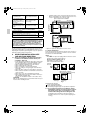
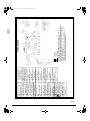
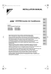
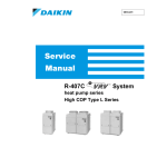
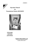
00_CV_3P249378-5G.fm Page 1 Thursday, December 8, 2011 4:16 PM INSTALLATION MANUAL English SPLIT SYSTEM Air Conditioners Deutsch MODELS (Ceiling suspended Cassette type) FUY71FJV1 FUY100FJV1 FUY125FJV1 FUYP71BV1 FUYP100BV1 FUYP125BV1 Français FUQ71BUV1B FUQ100BUV1B FUQ125BUV1B FUQ71BVV1B FUQ100BVV1B FUQ125BVV1B FUQ71BWV1B FUQ100BWV1B FUQ125BWV1B Español Italiano READ THESE INSTRUCTIONS CAREFULLY BEFORE INSTALLATION. KEEP THIS MANUAL IN A HANDY PLACE FOR FUTURE REFERENCE. LESEN SIE DIESE ANWEISUNGEN VOR DER INSTALLATION SORGFÄLTIG DURCH. BEWAHREN SIE DIESE ANLEITUNG FÜR SPÄTERE BEZUGNAHME GRIFFBEREIT AUF. ÅëëçíéêÜ LIRE SOIGNEUSEMENT CES INSTRUCTIONS AVANT L’INSTALLATION. CONSERVER CE MANUEL A PORTEE DE MAIN POUR REFERENCE ULTERIEURE. Nederlands LEA CUIDADOSAMENTE ESTAS INSTRUCCIONES ANTES DE INSTALAR. GUARDE ESTE MANUAL EN UN LUGAR A MANO PARA LEER EN CASO DE TENER ALGUNA DUDA. Portugues PRIMA DELL’INSTALLAZIONE LEGGERE ATTENTAMENTE QUESTE ISTRUZIONI. TENERE QUESTO MANUALE A PORTATA DI MANO PER RIFERIMENTI FUTURI. ÄΙΑΒΑΣΤΕ ΠΡΟΣΕΚΤΙΚΑ ΑΥΤΕΣ ΤΙΣ ΟÄΗΓΙΕΣ ΠΡΙΝ ΑΠΟ ΤΗΝ ΕΓΚΑΤΑΣΤΑΣΗ ΕΧΕΤΕ ΑΥΤΟ ΤΟ ΕΓΧΕΙΡΙÄΙΟ ΕΥΚΑΙΡΟ ΓΙΑ ΝΑ ΤΟ ΣΥΜΒΟΥΛΕΥΕΣΤΕ ΣΤΟ ΜΕΛΛΟΝ. LEES DEZE INSTRUCTIES ZORGVULDIG DOOR VOOR INSTALLATIE. BEWAAR DEZE HANDLEINDING WAAR U HEM KUNT TERUGVINDEN VOOR LATERE NASLAG. LEIA COM ATENÇÃO ESTAS INSTRUÇÕES ANTES DE REALIZAR A INSTALAÇÃO. MANTENHA ESTE MANUAL AO SEU ALCANCE PARA FUTURAS CONSULTAS. ПЕРЕД НАЧАЛОМ МОНТАЖА ВНИМАТЕЛЬНО ОЗНАКОМЬТЕСЬ С ДАННЫМИ ИНСТРУКЦИЯМИ. СОХРАНИТЕ ДАННОЕ РУКОВОДСТВО В МЕСТЕ, УДОБНОМ ДЛЯ ОБРАЩЕНИЯ В БУДУЩЕМ. Ðóññêèé tekigousenn_01.fm Page 1 Wednesday, November 19, 2003 8:15 PM CE - DECLARATION OF CONFORMITY CE - KONFORMITÄTSERKLÄRUNG CE - DECLARATION DE CONFORMITE CE - CONFORMITEITSVERKLARING CE - DECLARACION DE CONFORMIDAD CE - DICHIARAZIONE DI CONFORMITA’ CE - ÄΗΛÙΣΗΣΥΜΜΟΡΦÙΣΗΣ CE - DECLARAÇÃO DE CONFORMIDADE CE - OPFYLDELSESERKLÆRING CE - FÖRSÄKRAN OM ÖVERENSTÄMMELSE CE - ERKLÆRING OM SAMSVAR CE - ILMOITUS YHDENMUKAISUUDESTA DAIKIN INDUSTRIES, LTD. declares under its sole responsibility that the air conditioning models to which this declaration relates: erklärt auf seine alleinige Verantwortung daß die Modelle der Klimageräte für die diese Erklärung bestimmt ist: déclare sous sa seule responsabilité que les appareils d’air conditionné visés par la présente déclaration: verklaart hierbij op eigen exclusieve verantwoordelijkheid dat de airconditioning units waarop deze verklaring betrekking heeft: declara baja su única responsabilidad que los modelos de aire acondicionado a los cuales hace referencia la declaración: dichiara sotto sua responsabilità che i condizionatori modello a cui è riferita questa dichiarazione: δηλþνει ìε αποκλειστικÞ τηò ευθýνη üπ τα ìοντÝλα των κλιìατιστικþν συσκευþν στα oπoßα αναφÝρεται η παροýσα δÞλωση: declara sob sua exclusiva responsabilidade que os modelos de ar condicionado a que esta declaração se refere: erklærer under eneansvar, at klimaanlægmodellerne, som denne deklaration vedrører: deklarerar i egenskap av huvudansvarig, att luftkonditioneringsmodellerna som berörs av denna deklaration innebär att: erklærer et fullstendig ansvar for at de luftkondisjoneringsmodeller som berøres av denne deklarasjon innebærer at: ilmoittaa yksinomaan omalla vastuullaan, että tämän ilmoituksen tarkoittamat ilmastointilaitteiden mallit: ( ) ( ) FAY71FJV1, FAY100FJV1 FHYK35FJV1, FHYK45FJV1, FHYK60FJV1, FHYK71FJV1, FHK35FJV1, FHK45FJV1, FHK60FJV1 FHY35BJV1, FHY45BJV1, FHY60BJV1, FHY71BJV1, FHY100BJV1, FHY125BJV1, FH35BJV1, FH45BJV1, FH60BJV1 FUY71FJV1, FUY100FJV1, FUY125FJV1 FAYP71BV1, FAYP100BV1 FHYKP35BV1, FHYKP45BV1, FHYKP60BV1, FHYKP71BV1, FHK35BZV1, FHK45BZV1, FHK60BZV1 FHYP35BV1, FHYP45BV1, FHYP60BV1, FHYP71BV1, FHYP100BV1, FHYP125BV1, FH35BZV1, FH45BZV1, FH60BZV1 FUYP71BV1, FUYP100BV1, FUYP125BV1 are in conformity with the following standard(s) or other normative document(s), provided that these are used in accordance with our instructions: der/den folgenden Norm(en) oder einem anderen Normdokument oder -dokumenten entspricht/entsprechen, unter der Voraussetzung, daß sie gemäß unseren Anweisungen eingesetzt werden: sont conformes à la/aux norme(s) ou autre(s) document(s) normatif(s), pour autant qu’ils soient utilisés conformément à nos instructions: conform de volgende norm(en) of één of meer andere bindende documenten zijn, op voorwaarde dat ze worden gebruikt overeenkomstig onze instructies: están en conformidad con la(s) siguiente(s) norma(s) u otro(s) documento(s) normativo(s), siempre que sean utilizados de acuerdo con nuestras instrucciones: sono conformi al(i) seguente(i) standard(s) o altro(i) documento(i) a carattere normativo, a patto che vengano usati in conformità alle nostre istruzioni: εßναι σýìφωνα ìε το(α) ακüλουθο(α) πρüτυπο(α) Þ Üλλο Ýγγραφο(α) κανονισìþν, υπü την προϋπüθεοη üτι χρησιìοιτοιοýνται σýìφωνα ìε τιò οδηγßεò ìαò: eatão em conformidade com a(s) seguinte(s) norma(s) ou outro(s) documento(s) normativo(s), desde que estes sejam utilizados de acordo com as nossas instruções: overholder følgende standard(er) eller andet/andre retningsgivende dokument(er), forudsat at disse anvendes i henhold til vore instrukser: respektive utrustning är utförd i överensstämmelse med och följer följande standard(er) eller andra normgivande dokument, under förutsättning att användning sker iöverensstämmelse med vära instruktioner: respektive utstyr er i overensstemmelse med følgende standard(er) eller andre normgivende dokument(er), under forutssetning av at disse brukes i henhold til våre instrukser: vastaavat seuraavien standardien ja muiden ohjeellisten dokumenttien vaatimuksia edellyttäen, että niitä käytetään ohjeidemme mukaisesti: EN60335-2-40, following the provisions of: Directives, as amended. gemäß den Vorschriften der: Direktiven, gemäß Änderung. conformément aux stipulations des: Directives, telles que modifiées. overeenkomstig de bepalingen van: Richtlijnen, zoals geamendeerd. siguiendo las disposiciones de: Directivas, según lo enmendado. Low Voltage 73/23/EEC* secondo le prescrizioni per: Direttive, come da modifica. Machinery Safety 89/392/EEC* ìε τÞρηση των διατÜξεων των: Οδηγιþν, üπωò Ýχουν τροποποιηθεß. de acordo com o previsto em: Directivas, conforme alteração em. Electromagnetic Compatibility 89/336/EEC* under iagttagelse af bestemmelserne i: Direktiver, med senere ændringer. enligt villkoren i: Direktiv, med företagna ändringar. gitt i henhold til bestemmelsene i: Direktiver, med foretatte endringer. noudattaen määräyksiä: Direktilvejä, sellaisina kuin ne ovat muutettuina. ( ) *Note as set out in the Technical Construction File DAIKIN.TCF.004 and judged positively by KEMA according to the Certificate 59277-KRQ/ECM95-4233. *Hinweis wie in der Technischen Konstruktionsakte DAIKIN.TCF.004 aufgeführt und von KEMA positiv ausgezeichnet gemäß Zertifikat 59277-KRQ/ECM95-4233. *Remarque tel que stipulé dans le Fichier de Construction Technique DAIKIN.TCF.004 et jugé positivement par KEMA conformément au Certificat 59277-KRQ/ECM95-4233. *Bemerk zoals vermeld in het Technisch Constructiedossier DAIKIN.TCF.004 en in orde bevonden door KEMA overeenkomstig Certificaat 59277-KRQ/ECM95-4233. *Nota tal como se expone en el Archivo de Construcción Técnica DAIKIN.TCF.004 y juzgado positivamente por KEMA según el Certificado 59277-KRQ/ECM95-4233. *Nota delineato nel File Tecnico di Costruzione DAIKIN.TCF.004 e giudicato positivamente da KEMA secondo il Certificato 59277-KRQ/ECM95-4233. *Σηìεßωση üπωò προσδιορßζεται στο Αρχεßο ΤεχνικÞò ΚατασκευÞò DAΙΚΙΝ.ΤCF.004 και κρßνεται θετικÜ απü το ΚΕΜΑ σýìφωνα ìε το Πιστοποιητικü 59277-ΚRQ/ΕCΜ95-4233. *Nota tal como estabelecido no Ficheiro Técnico de Construção DAIKIN.TCF.004 e com o parecer positivo de KEMA de acordo com o Certificado 59277-KRQ/ECM95-4233. *Bemærk som anført i den Tekniske Konstruktionsfil DAIKIN.TCF.004 og positivt vurderet af KEMA i henhold til Certifikat 59277-KRQ/ECM95-4233. *Information utrustningen är utförd i enlighet med den Tekniska Konstruktionsfilen DAIKIN.TCF.004 som positivt intygas av KEMA vilket också framgår av Certifikat 59277-KRQ/ECM95-4233. *Merk som det fremkommer i den Tekniske Konstruksjonsfilen DAIKIN.TCF.004 og gjennom positiv bedømmelse av KEMA ifølge Sertifikat 59277-KRQ/ECM95-4233. *Huom jotka on esitetty Teknisessä Asiakirjassa DAIKIN.TCF.004 ja jotka KEMA on hyväksynyt Sertifikaatin 59277-KRQ/ECM95-4233. ( ) *Note as set out in the Technical Construction File DAIKIN.TCF.016 and judged positively by KEMA according to the Certificate 81728-KRQ/ECM98-4341. *Hinweis wie in der Technischen Konstruktionsakte DAIKIN.TCF.016 aufgeführt und von KEMA positiv ausgezeichnet gemäß Zertifikat 81728-KRQ/ECM98-4341. *Remarque tel que stipulé dans le Fichier de Construction Technique DAIKIN.TCF.016 et jugé positivement par KEMA conformément au Certificat 81728-KRQ/ECM98-4341. *Bemerk zoals vermeld in het Technisch Constructiedossier DAIKIN.TCF.016 en in orde bevonden door KEMA overeenkomstig Certificaat 81728-KRQ/ECM98-4341. *Nota tal como se expone en el Archivo de Construcción Técnica DAIKIN.TCF.016 y juzgado positivamente por KEMA según el Certificado 81728-KRQ/ECM98-4341. *Nota delineato nel File Tecnico di Costruzione DAIKIN.TCF.016 e giudlcato positivamente da KEMA secondo il Certificato 81728-KRQ/ECM98-4341. *Σηìεßωση üπωò προσδιορßζεται στο Αρχεßο ΤεχνικÞò ΚατασκευÞò DAΙΚΙΝ.ΤCF.016 και κρßνεται θετικÜ απü το ΚΕΜΑ σýìφωνα ìε το Πιστοποιητικü 81728-KRQ/ECM98-4341. *Nota tal como estabelecido no Ficheiro Técnico de Construção DAIKIN.TCF.016 e com o parecer positivo de KEMA de acordo com o Certificado 81728-KRQ/ECM98-4341. *Bemærk som anført i den Tekniske Konstruktionsfil DAIKIN.TCF.016 og positivt vurderet af KEMA i henhold til Certifikat 81728-KRQ/ECM98-4341. *Information utrustningen är utförd i enlighet med den Tekniska Konstruktionsfilen DAIKIN.TCF.016 som positivt intygas av KEMA vilket också framgår av Certifikat 81728-KRQ/ECM98-4341. *Merk som det fremkommer i den Tekniske Konstruksjonsfilen DAIKIN.TCF.016 og gjennom positiv bedømmelse av KEMA ifølge Sertifikat 81728-KRQ/ECM98-4341. *Huom jotka on esitetty Teknisessä Asiakirjassa DAIKIN.TCF.016 ja jotka KEMA on hyväksynyt Sertifikaatin 81728-KRQ/ECM98-4341 mukaisesti. Yoshiaki Hirata Manager Quality Control Department Sakai, 1st of December 2000 Umeda Center Bldg., 4-12, Nakazaki-Nishi 2-chome, Kita-ku, Osaka, 530-8323 Japan 3P064660-1A FHY35BJV1, FHY45BJV1, FHY60BJV1, FHY71BJV1, FHY100BJV1, FHY125BJV1, FH35BJV1, FH45BJV1, FH60BJV1 EN60335-2-40, FVQ71BV1B, FVQ100BV1B, FVQ125BV1B FAQ71BUV1B, FAQ100BUV1B, FAQ71BVV1B, FAQ100BVV1B Low Voltage 2006/95/EC Machinery Safety 98/37/EC Electromagnetic Compatibility 2004/108/EC Shinri Sada Manager Quality Control Department 1st of April 2009 FUQ71BUV1B, FUQ100BUV1B, FUQ125BUV1B, FUQ71BVV1B, FUQ100BVV1B, FUQ125BVV1B FHQ35BVV1B, FHQ50BVV1B, FHQ60BVV1B, FHQ71BVV1B, FHQ100BVV1B, FHQ125BVV1B (III) FHQ35BUV1B, FHQ50BUV1B, FHQ60BUV1B, FHQ71BUV1B, FHQ100BUV1B, FHQ125BUV1B (II) FHYP35BV1, FHYP45BV1, FHYP60BV1, FHYP71BV1, FHYP100BV1, FHYP125BV1, FH35BZV1, FH45BZV1, FH60BZV1 (I) DAIKIN INDUSTRIES, LTD. (I) (II) (III) DAIKIN.TCF.004J1/ DAIKIN.TCF.016D1/ DAIKIN.TCF.021E5/ 07-2007 07-2007 11-2007 Umeda Center Bldg., 2-4-12, Nakazaki-Nishi, Kita-ku, Osaka, 530-8323 Japan <C> 59277-KRQ/ ECM95-4233 81728-KRQ/ ECM98-4341 2024351-QUA/ EMC02-4565 <B> KEMA Quality B.V. KEMA Quality B.V. KEMA Quality B.V. <A> 3P104327-1F.fm Page 1 Friday, April 10, 2009 10:35 AM 3P104327-1F 01_EN_3P249378-5G.fm Page 1 Friday, January 20, 2012 2:01 PM FUY71FJV1 FUYP71BV1 FUQ71BUV1B FUQ71BVV1B FUQ71BWV1B FUY100FJV1 FUYP100BV1 FUQ100BUV1B FUQ100BVV1B FUQ100BWV1B SPLIT SYSTEM Air Conditioner Installation manual FUY125FJV1 FUYP125BV1 FUQ125BUV1B FUQ125BVV1B FUQ125BWV1B CONTENTS 1. SAFETY PRECAUTIONS ............................................ 1 2. BEFORE INSTALLATION ............................................ 2 3. SELECTING INSTALLATION SITE AND AIR FLOW DIRECTION ...................................... 3 4. PREPARATIONS BEFORE INSTALLATION ............... 4 5. INDOOR UNIT INSTALLATION ................................... 7 6. REFRIGERANT PIPING WORK .................................. 8 7. DRAIN PIPING WORK ................................................. 9 8. ELECTRIC WIRING WORK ....................................... 11 9. WIRING EXAMPLE .................................................... 12 10. FIELD SETTING ........................................................ 12 11. INSTALLATION OF CORNER COVER AND AIR INTAKE GRILLE ......................................... 14 12. TEST OPERATION .................................................... 14 13. WIRING DIAGRAM .................................................... 16 This English text is the original instruction. Other languages are translations of the original instructions. 1. SAFETY PRECAUTIONS Please read these “SAFETY PRECAUTIONS” carefully before installing air conditioning equipment and be sure to install it correctly. Meaning of WARNING and CAUTION notices. Both are important notices for safety. Be sure to follow them. WARNING ............. Failure to follow these instructions properly may result in personal injury or loss of life. CAUTION................Failure to observe these instructions properly may result in property damage or personal injury, which may be serious depending on the circumstances. After completing installation, conduct a test operation to confirm that the equipment operates without any problems. Then, explain to the customer how to operate the equipment and take care of it following the operation manual. Ask the customer to store the installation manual along with the operation manual for future reference. This air conditioner comes under the term “appliances not accessible to the general public”. WARNING • Ask your dealer or qualified personnel to carry out installation work. Do not attempt to install the air conditioner yourself. Improper installation may result in water leakage, electric shocks or fire. • Install the air conditioner in accordance with the instructions in this installation manual. Improper installation may result in water leakage, electric shocks or fire. • When installing the unit in a small room, take measures so that the refrigerant may not exceed the limiting concentration in the event of refrigerant leakage. Contact your dealer for further information. If the refrigerant leaks and exceeds the limiting concentration, it may lead to oxygen deficiency. • Be sure to use only the specified accessories and parts for installation work. Failure to use the specified parts may result in the unit falling, water leakage, electric shocks or fire. • Install the air conditioner on a foundation strong enough to withstand the weight of the unit. If a foundation does not have sufficient strength, the equipment may fall and cause injury. 1 • Carry out the required installation work in consideration of strong winds, typhoons or earthquakes. If the installation work is not properly carried out, the unit may fall down and cause accidents. • The electrical work must be carried out by the qualified electrician in accordance with the local laws and regulations and this installation manual. Make sure to provide a dedicated power supply circuit and never connect additional wiring to the existing circuit. An insufficient power supply capacity or improper electrical work may lead to electric shocks or fire. • Be sure to earth the air conditioner. Do not earth the unit to a utility pipe, lightning conductor or telephone earth lead. Imperfect earthing may result in electric shocks or fire. A high surge current from lightning or other sources may cause damage to the air conditioner. • Be sure to install an earth leakage breaker. Failure to install an earth leakage breaker may result in electric shocks or fire. • Be sure to switch off the unit before touching any electrical parts. Touching a live part may result in electric shock. • For wiring, use the specified wires and connect and fasten them firmly so that no external force from the wires may be applied to the terminal connections. If the wires are not firmly connected and fastened, it may cause heating, fire or the like. • Wiring for power supply and between the indoor and outdoor units must be properly laid and formed, and the control box lid must be firmly fastened so that the wiring may not push up the structural parts such as the lid. If the lid is improperly fastened, it may cause electric shock or fire. • If refrigerant gas leaks during installation, ventilate the area immediately. Toxic gas may be produced if the refrigerant comes into contact with fire. • After completing installation, check for refrigerant gas leakage. Toxic gas may be produced if the refrigerant gas leaks into the room and comes into contact with a source of fire, such as a fan heater, stove or cooker. • Do not directly touch refrigerant that has leaked from refrigerant pipes or other areas, as there is a danger of frostbite. CAUTION • Carry out drain piping properly following this installation manual and insulate the pipe to prevent condensation. Improper drain piping may result in indoor water leakage and property damage. • Install the indoor and outdoor units, power supply and transmission wirings at least 1 meter away from televisions or radios to prevent picture interference and noise. (Depending on the incoming signal strength, a distance of 1 meter may not be sufficient to eliminate noise.) • Install the indoor unit as far as possible from fluorescent lamps. If a wireless kit is installed in a room where the electronic lighting type (inverter or rapid start types) fluorescent lamps exist, the transmitting distance of a remote controller may be shorter. • Do not install the air conditioner in the following locations: 1. Where there is a high concentration of mineral oil spray or vapour (e.g. a kitchen). Plastic parts may deteriorate and cause parts to fall off or water to leak. 2. Where corrosive gas, such as sulphurous acid gas, is produced. Corrosion of copper pipes or brazed parts may occur and cause refrigerant leakage. English 01_EN_3P249378-5G.fm Page 2 Friday, January 20, 2012 2:01 PM 3. Where there is a machine that generates electromagnetic wave and where voltage fluctuation often occurs such as a factory. Control system may malfunction and as a result the unit may not properly operate. 4. Where flammable gas may leak, where carbon fibre or ignitable dust is suspending in the air, or where volatile flammables such as paint thinner or gasoline are handled. Operating the unit in such conditions may result in fire. • The air conditioner is not intended for use in a potentially explosive atmosphere. Name Quantity BEFORE INSTALLATION 2-1 PRECAUTIONS • Be sure to read this manual before installing the indoor unit. • When selecting installation site, refer to the paper pattern. • This unit is suitable for installation in a household, commercial and light industrial environment. • Do not install or operate the unit in rooms mentioned below. • Laden with mineral oil, or filled with oil vapor or spray like in kitchens. (Plastic parts may deteriorate.) • Where corrosive gas like sulfurous gas exists. (Copper tubing and brazed spots may corrode.) • Where volatile flammable gas like thinner or gasoline is used. • Where machines can generate electromagnetic waves. (Control system may malfunction.) • Where the air contains high levels of salt such as that near the ocean and where voltage fluctuates greatly such as that in factories. Also in vehicles or vessels. 2-2 ACCESSORIES Check the following accessories are included with the unit. Name Quantity 1) Drain hose 1 pc. 2) Clamp 1 pc. 3) Washer for hanging bracket 8 pcs. Shape Name Quantity 4) Clamp 6 pcs. 5) Wahers fixing plate 4 pcs. 1 pc. Insulation for fitting 1 each 6) For gas pipe Shape 7) For liquid pipe 12) Retainer for blocking pad 2 pcs. 2 pcs. 10) Paper pattern for installation 1 pc. Also used as packing material 13) Retainer for blocking pad 2 pcs. Shape Name Quantity 14) Center retainer for blocking pad 2 pcs. Shape (Other) • Operation manual • Installation manual 2-3 OPTIONAL ACCESSORIES • The remote controller are required for this indoor unit. (However, the remote controller is not required for the slave unit of a simultaneous operation system.) These are two types of remote controllers: wired and wireless. Select a remote controller from Table 1 according to customer request and install in an appropriate place. (For installation, follow the Installation manual included with the remote controllers.) Table 1 Remote controller Wired type Wireless type Heat pump type Cooling only type Model BRC1C517, BRC1C61, BRC1D527, BRC1D528 BRC1B517, BRC1B61 BRC7C (A) 528W BRC7C (A) 529W NOTE • If you wish to use a remote controller that is not listed in Table 1, select a suitable remote controller after consulting catalogs and technical materials. FOR THE FOLLOWING ITEMS, TAKE SPECIAL CARE DURING CONSTRUCTION AND CHECK AFTER INSTALLATION IS FINISHED. 1. Items to be checked after completion of work Items to be checked If not properly done, what is likely to occur The unit may drop, vibrate or make noise. It may result in insufficient cooling. Condensate water may drip. Condensate water may drip. Check Is the indoor unit fixed firmly? Is the gas leak test finished? Is the unit fully insulated? Does drainage flow smoothly? Does the power supply The unit may malfunction voltage correspond to the components burn that shown on the name or out. plate? The unit may malfunction Are wiring and piping or the components burn correct? out. Is the unit safely grounded? English 1 pc. 11) Blocking pad Quantity Do not exert pressure on the resin parts when opening the unit or when moving it after opening. • When moving the unit while removing it from the box, be sure to lift it by holding on to the four lifting lugs without exerting any pressure on other parts, especially swing flap, the refrigerant piping, drain piping, and other resin parts. • Decide upon a line of transport. • Leave the unit inside its packaging while moving, until reaching the installation site. Use a sling of soft material, where unpacking is unavoidable or protective plates together with a rope when lifting, to avoid damage or scratches to the unit. • Refer to the installation manual of the outdoor unit for items not described in this manual. • Installation should only be carried out after checking in advance the type of refrigerant to be used. (Using the wrong refrigerant will prevent the unit from functioning properly.) • Do not dispose of any parts necessary for installation until the installation is complete. 9) Elbow Shape Name 2. 8) Sealing pad Dangerous at electric leakage. 2 01_EN_3P249378-5G.fm Page 3 Friday, January 20, 2012 2:01 PM • Install the indoor unit no less than 2.5m above the floor. Where unavoidably lower, take what measures are necessary to keep hands out of the air outlet. The unit may malfunction or the components burn out. Be sure to instruct customers how to properly operate the unit (especially cleaning filters, operating different functions, and adjusting the temperature) by having them carry out operations themselves while looking at the manual. 3. SELECTING INSTALLATION SITE AND AIR FLOW DIRECTION 3-1 Select an installation site where the following conditions are fulfilled and that meets your customer’s approval. • In the upper space (including the back of the ceiling) of the indoor unit where there is no possible dripping of water from the refrigerant pipe, drain pipe, water pipe, etc. • Where optimum air distribution can be ensured. • Where nothing blocks air passage. • Where condensate can be properly drained. • Where the ceiling is strong enough to bear the indoor unit weight. • Where the false ceiling is not noticeably on an incline. • Where sufficient clearance for maintenance and service can be ensured. • Where there is no risk of flammable gas leakage. • Where piping between indoor and outdoor units is possible within the allowable limit. (Refer to the installation manual for the outdoor unit.) [CAUTION] Only use the included parts or parts which match the specifications when installing the unit. ≥ 1000 Floor Air discharge The items with WARNING and CAUTION marks in the instruction manual are the items pertaining to possibilities for bodily injury and material damage in addition to the general usage of the product. Accordingly, it is necessary that you make a full explanation about the described contents and also ask your customers to read the instruction manual. 2-4 NOTE TO THE INSTALLER Air inlet ≥ 1500 Obstruction ≥ 1500 ≥ 1000 Check ≥ 2500 Items to be checked Did you explain about operations while showing the instruction manual to your customer? Did you hand the instruction manual over to your customer? Points for explanation about operations ≥ 1500 Air inlet ≥ 2500 Space required for installation Air discharge Air discharge Is something blocking the air outlet or inlet of It may result in insuffieither the indoor or out- cient cooling. door units? Are refrigerant piping length and additional The refrigerant charge in refrigerant charge noted the system is not clear. down? 2. Items to be checked at time of delivery ∗Also review the “SAFETY PRECAUTIONS” For installation in high places. Is wiring size according to specifications? ≥ 30∗∗ Obstruction Floor ** Space is required to attach/detach corner covers. 3-2 Air flow direction Select the air flow direction that best suits the unit’s location. 2way and 3-way air flow must be set from the remote controller. For details, see FIELD SETTING. NOTE • Restrictions are placed on piping direction, therefore select flow direction from the below patterns. [Air flow patterns] (Refer to Fig. 1) (IIlustrations seen from ceiling) A, B, C and D indicate drain pans. Air flow direction C D B D C D B C A A 4-way air discharge 3-way air 3-way air discharge discharge Optional parts required (Back-to-back blocking pad kit) C C D A 2-way air discharge 2-way air discharge Fig. 1 Refrigerant pipe direction To the rear (Straight pipe) To the right (Elbow required) Upward running refrigerant pipes are possible in all patterns. 3-3 Use suspension bolts for installation. Check whether the ceiling is strong enough to support the weight of the unit or not. If there is a risk, reinforce the ceiling before installing the unit. (Installation pitch is marked on the paper pattern for installation. Refer to it to check for points requiring reinforcing.) 3 English 01_EN_3P249378-5G.fm Page 4 Friday, January 20, 2012 2:01 PM 4. PREPARATIONS BEFORE INSTALLATION Hold the indoor unit by the hanger brackets when carrying. 4-1 FOR 4-WAY AIR DISCHARGE 1. Relation of holes for indoor unit, suspension bolt position, piping and wiring. (Refer to Fig. 2) (Illustrations seen from ceiling) 895 790∗∗∗ B 180 83 30 D 790∗∗∗ 895 C 33 A 163 Upward running drain pipe shown above Fig. 5 • Open the air intake grille to a 45° angle and detach from the unit. • Detach the corner covers. [TO CHANGE AIR FLOW RATE] • When shipped from the factory, the shutters on air discharge outlets C and D are closed so that air flow rate is the same in all four directions. • Air flow rate can be changed by sliding the shutter. (Refer to Fig. 6 and 7) ∗ 40 (107) ∗ 58 (125) ∗ 80 (147) Drain hose connection (VP20) Shutter Liquid pipe Gas pipe Fig. 2 ∗ Dimensions in ( ) for 100 and 125 models ∗∗∗ Suspension bolt pitch 2. Make holes for suspension bolts, refrigerant and drain piping, and wiring. (Refer to Fig. 3) • Refer to the paper patten for the locations. • Select the location for each of holes and open the holes in the ceiling. Fig. 6 NOTE • Ilustration seen from ceiling C Ceiling slab D B 50-100 Anchor Shutter Piping area False ceiling Long nut or turnbuckle Suspension bolt Fig. 3 (Use either a M8-M10 size bolt) Use a hole-in anchor for existing ceilings, and a sunken insert, sunken anchor or other field supplied parts for new ceilings to reinforce the ceiling to bear the weight of the unit. Adjust clearance from the false ceiling before proceeding further. 3. Detach the air intake grille and corner covers from the indoor unit. • Detach the air intake grille. (Refer to Fig. 4 and 5) • Slide the locking knobs (×2) on the air intake grille inward (direction of arrows) and lift upwards. Air intake grille Cornercover (×4) English Air discharge outlet Shutter (Indicates drain pan.) C B NOTE • All the above parts are field supplied. Fig. 4 A D Piping area A When shipped from factory Moderate flow rate C D B Moderate flow rate Moderate flow rate B A Moderate flow rate A C D 4 01_EN_3P249378-5G.fm Page 5 Friday, January 20, 2012 2:01 PM • Select the location for each of holes and open the holes in the ceiling. C Moderate flow rate Moderate flow rate B Ceiling slab Anchor 50-100 D A Moderate flow rate Long nut or turnbuckle False ceiling Suspension bolt Fig. 9 C NOTE • To change air flow rate, select a pattern from “TO CHANGE AIR FLOW RATE” and determine the location of pipes. • All the above parts are field supplied. B D Moderate flow rate A (Use either a M8-M10 size bolt.) Use a hole-in anchor for existing ceilings, and a sunken insert, sunken anchor or other field supplied parts for new ceilings to reinforce the ceiling to bear the weight of the unit. Adjust clearance from the false ceiling before proceeding further. Fig. 7 CAUTION Be careful not to touch the heat exchanger fins. [CEILING HEIGHT] The indoor unit may be installed on ceilings up to 3.5m in height. However, it becomes necessary to make field settings by remote controller when installing the unit at a height over 2.7m. Refer to the section entitled “FIELD SETTING” and the decoration panel installation manual. Install this unit where the height of bottom panel is more than 2.5m so that user cannot easily touch. 3. Detach the air intake grille and corner covers from the indoor unit. Air intake grille Cornercover (×4) 4-2 FOR 2-WAY OR 3-WAY AIR DISCHARGE 2-way and 3-way air discharge must be set from the remote controller. For details, see FIELD SETTING. 1. Relation of holes for indoor unit, suspension bolt position, piping and wiring. (Refer to Fig. 8) Hold the indoor unit by the hanger brackets when carrying. 895 790∗∗∗ A ∗ 40 (107) ∗ 58 (125) ∗ 80 (147) 33 83 180 30 D 895 B 790∗∗∗ C 117 Rightward running drain pipe shown above Fig. 10 • Detach the air intake grille. (Refer to Fig. 10) • Slide the locking knobs (×2) on the air intake grille inward (direction of arrows) and lift upwards. • Open the air intake grille to a 45° angle and detach from the unit. • Detach the corner covers. [THE WAY TO BLOCK AIR DISCHARGE OUTLETS] For 2-way air discharge, outlets A and B must be blocked. For 3-way air discharge, outlets A or B must be blocked. 1. Detach the top decorative plate from the outlets to be blocked. (Refer to Fig. 11) Liquid pipe Gas pipe Fig. 8 Drain hose connection (VP20) NOTE • Illustrations seen from ceiling ∗ Dimension in ( ) for 100 and 125models ∗∗∗ Suspension bolt pitch 2. Make holes for suspension bolts, refrigerant and drain piping, and wiring. (Refer to Fig. 9) • Refer to paper pattern for the locations. (Bottom) decorative plate Flap (Top) decorative plate Screw for top decorative plate Fig. 11 2. Detach the flap from the outlets, too. 5 English 01_EN_3P249378-5G.fm Page 6 Friday, January 20, 2012 2:01 PM 3. Attach the retainers to the blocking pad. (Refer to Fig. 12) Align the projections on the pads with the holes on the retainers, and tape parts together with 2-sided tape. C Retainers for blocking pad (12)(13) B D Blocking pad (11) Projection Shutter Piping area Hole A Air discharge outlet (Indicates drain pan.) Blocking pad Fig. 12 C 2-sided tape B 4. After installing the blocking pads, attach the center blocking pad retainer and the top decorative panel. (Refer to Fig. 13) Piping area D A Shutter Moderate flow rate Center retainer for blocking pad (14) Screw for top decorative plate Insert here. C B D Top decorative plate Insert here. A Center retainer for blocking pad (14) Blocking pad C Moderate flow rate B Bottom decorative plate Blocking pad D A Top decorative plate C Moderate flow rate Fig. 13 B D CAUTION Unless blocking pads are installed as indicated, air will leak and consequently cause dewing. [TO CHANGE AIR FLOW RATE] • When shipped from the factory, the shutters on air discharge outlets C and D are closed so that air flow rate is the same in all four directions. • Air flow rate can be changed by sliding the shutter. (Refer to Fig. 14) A Shutter Fig. 14 CAUTION Be careful not to touch the heat exchanger fins. Blocking pad C D A Moderate flow rate Fig. 15 2-way air discharge (Refer to Fig. 15) NOTE • Illustrations seen from ceiling English 6 01_EN_3P249378-5G.fm Page 7 Friday, January 20, 2012 2:01 PM 5. 3-way air discharge (Refer to Fig. 16) C D B Piping area 5-1 Fit the top nuts and washers over the suspension bolts (×4). A Shutter C B INDOOR UNIT INSTALLATION Installing optional accessories before installing the indoor unit is easier. As for the parts to be used for installation work, be sure to use the provided accessories and specified parts designated by our company. • Use the washer fixing plate (5) to keep the washer from falling out of place. Hang the unit from the hangers on side A, and then fit the bottom washers and nuts over the suspension bolts on that side. (Refer to Fig. 17) Piping area A A Piping area B D Insert below washer. Washer fixing plate (5) (attached) Shutter Blocking pad D C C Securing the washer Fig. 17 Moderate flow rate 5-2 Install the indoor unit. (Refer to Fig. 18) D B Field procedurement A Moderate flow rate • Lock the unit to the hangers on side A. • Hook the unit onto the other 2 hangers and lock with bottom washers and nuts. Hanger bracket C B A Washers (3) (attached) (For locking hanger) Tighten (double nuts.) D Fig. 18 Blocking pad 5-3 Check whether the unit is horizontally level from sides C and D both. (Refer to Fig. 19) C Piping area A B D A Blocking pad B Moderate flow rate D Horizontally level check C Horizontally level Fig. 19 C A Moderate flow rate Fig. 16 CAUTION D [CEILING HEIGHT] The indoor unit may be installed on ceilings up to 3.5 m in height. However, it becomes necessary to make field settings by remote controller when installing the unit at a height over 2.7m. Refer to the section entitled “FIELD SETTING” and the decoration panel installation manual. Install this unit where the height of bottom panel is more than 2.5m so that user cannot easily touch. 7 B • Do not hold the swing flap when mounting, as this may break it. • The indoor unit is equipped with a built-in drain pump and float switch. At each of the unit’s 4 corners, verify that it is level by using a water level or a waterfilled vinyl tube. (If the unit is tilted against condensate flow, the float switch may malfunction and cause water to drip.) 5-4 Remove the washer fixing plate (5) used for preventing the washer from falling and tighten the upper nut. English 01_EN_3P249378-5G.fm Page 8 Friday, January 20, 2012 2:01 PM REFRIGERANT PIPING WORK 〈For refrigerant piping of outdoor units, see the installation manual attached to the outdoor unit.〉 〈Execute heat insulation work completely on both sides of the gas piping and the liquid piping. Otherwise, a water leakage can result sometimes.〉 (When using a heat pump, the temperature of the gas piping can reach up to approximately 120°C, so use insulation which is sufficiently resistant.) 〈Also, in cases where the temperature and humidity of the refrigerant piping sections might exceed 30°C or RH80 %, reinforce the refrigerant insulation. (20 mm or thicker) Condensation may form on the surface of the insulating material.〉 〈Before refrigerant piping work, check which type of refrigerant is used. Proper operation is not possible if the types of refrigerant are not the same.〉 CAUTION • When connecting the flare nut, apply ester oil or ether oil to the inside of the flare section, and spin 3-4 times before screwing in. (Refer to Fig. 22) Coat here with ester or ether oil. Fig. 22 CAUTION Do not let oil get on the screw holders on the dressing board. Oil can weaken the screw holders. Table 2 Flare dimensions A (mm) Type of refrigerant R22, R407C R410A Applicable model FUY-FJV1 FUQ FUYP-BV1 Pipe size Tightening torque 12.6 – 13.0 12.8 – 13.2 φ15.9(5/8”) 61.8-75.4 N • m 19.0 – 19.4 19.3 – 19.7 φ19.1(3/4”) 97.2-118.8 N • m 23.3 – 23.7 45˚±2˚ φ9.5(3/8”) 32.7-39.9 N • m Flare R0.4-0.8 A • Use a pipe cutter and flare suitable for the type of refrigerant. • Apply ester oil or ether oil around the flare section before connecting. • To prevent dust, moisuture or other foreign matter from infiltrating the tube, either pinch the end or cover it with tape. • Do not allow anything other than the designated refrigerant to get mixed into the refrigerant circuit, such as air, etc. If any refrigerant gas leaks while working on the unit, ventilate the room thoroughly right away. 90˚±2˚ 6. • Refer to “Table 2” to determine the proper tightening torque. 6-1 Refrigerant pipes can be run in 3 directions (Refer to Fig. 20) CAUTION • Over-tightening the flare nut may break it and/or cause the refrigerant to leak. Not recommendable but in case of emergency Upward running pipes You must use a torque wrench but if you are obliged to install the unit without a torque wrench, you may follow the installation method mentioned below. After the work is finished, make sure to check that there is no gas leak. When you keep on tightening the flare nut with a spanner, there is a point where the tightening torque suddenly increases. From that position, further tighten the flare nut the angle shown below: Rear running pipes Table 3 Right running pipes Fig. 20 • Use copper alloy seamless pipes (ISO 1337). • The outdoor unit is charged with refrigerant. • Be sure to use both a spanner and torque wrench together, when connecting or disconnecting pipes to/ from the unit. (Refer to Fig. 21) • Refer to the Table 2 for flare dimensions and tightening torque. Torque wrench Pipe size Further tightening angle φ9.5 (3/8”) φ15.9 (5/8”) φ19.1 (3/4”) 60 to 90 degrees 30 to 60 degrees 25 to 35 degrees • Make absolutely sure to execute heat insulation works on the pipe-connecting section after checking gas leakage by thoroughly studying the following figure and using the attached heat insulating materials for couplings (6) and (7). (Fasten both ends with the clamps (4).) (Refer to Fig. 23) Attach to tha root Insulation for gas pipe (6) (accessory) Spanner Recommended arm length of tool Approx. 200mm Approx. 300mm Approx. 450mm Insulation for liquid pipe (7) (accessory) Piping union Fig. 21 Flare nut NOTE • Use the flare nut included with the unit main body. English Clamp (4) (×4) (accessory) Fig. 23 8 01_EN_3P249378-5G.fm Page 9 Friday, January 20, 2012 2:01 PM CAUTION CAUTION For local insulation, be sure to insulate all the way to the pipe connections inside the machine. Exposed piping may cause leaking or burns on contact. Water pooling in the drainage piping can cause the drain to clog. Drain hose Drain hose (1) (For VP20 connection) (Procure in field.) Ceiling slab 1 - 1.5 m Hanger VP20 bracket Elbow (9) VP20 Sealing pad (8) 6-2 For upward and rightward running pipes ≤500 • Upward and rightward running pipes are easily rigged with the optional connecting elbow kit. • For upward running pipes, detach the pipe hole cover. • Once pipes are rigged, cut the pipe hole cover to size and reattach. Use scissors for cutting.(Refer to Fig. 24) Since there exists a possibility that small animals and insects might get inside the indoor unit, attach the wiring through covers and make sure there are no gaps in the through holes by applying putty or insulation (procured locally.) Clamp (2) Notes on upward running drain hose Fig. 26 For liquid pipe For gas pipe Pipe hole cover For wiring Rear running pipe GOOD For drain pipe Right running drain hose Fig. 24 • When doing this, block any gaps between the piping penetration lid and the pipes using putty to prevent dust from entering the indoor unit. • CAUTION CAUTION TO BE TAKEN WHEN BRAZING REFRIGERANT PIPING “Do not use flux when brazing refrigerant piping. Therefore, use the phosphor copper brazing filler metal (BCuP-2: JIS Z 3264/B-Cu93P-710/795: ISO 3677) which does not require flux.” (Flux has extremely harmful influence on refrigerant piping systems. For instance, if the chlorine based flux is used, it will cause pipe corrosion or, in particular, if the flux contains fluorine, it will damage the refrigerant oil.) • Before brazing local refrigerant piping, nitrogen gas shall be blown through the piping to expel air from the piping. If you brazing is done without nitrogen gas blowing, a large amount of oxide film develops inside the piping, and could cause system malfunction. • When brazing the refrigerant piping, only begin brazing after having carried out nitrogen substitution or while inserting nitrogen into the refrigerant piping. Once this is done, connect the indoor unit with a flared or a flanged connection. • Nitrogen should be set to 0.02MPa with a pressure-reducing valve if brazing while inserting nitrogen into the piping. (Refer to Fig. 25) Refrigerant piping Min. 1/100 gradient • • • • • WRONG Fig. 27 To keep the drain hose from sagging, space hanging wiring every 1 to 1.5m. (Refer to Fig. 26) Use only the included drain hose (1), (for rightward running drain hose) or elbow (9) (for upward running drain hose) and clamp (2). Fit the drain hose (1) or elbow (9) over the drain piping up to the neck and fasten tight with the clamp (2). Tighten the clamp (2) until the screw head is less than 4mm from the hose. Insulate the clamp (2) and drain hose or elbow (9) with the included sealing pad (8). (Refer to Fig. 28) Make sure that heat insulation work is executed on the following 2 spots to prevent any possible water leakage due to dew condensation. • Insulate the drain hose inside the building • Drain socket Pressure-reducing valve Taping Part to be Hands valve brazed Nitrogen Nitrogen Fig. 25 7. DRAIN PIPING WORK 7-1 Rig drain piping (Refer to Fig. 26) As for drain work, perform piping in such a manner that water can be drained properly. As for drain piping, the connection can be made from three different directions. • Employ a pipe with either the same diameter or with the diameter larger (excluding the raising section) than that of the connecting pipe (PVC pipe, nominal diameter 20mm, outside diameter 26mm). • Keep the drain pipe short and sloping downwards at a gradient of at least 1/100 to prevent air pockets from forming. (Refer to Fig. 27) 9 English 01_EN_3P249378-5G.fm Page 10 Friday, January 20, 2012 2:01 PM 7-2 After piping work is finished, check if drainage flows smoothly. Clamp (2) • Open the water inlet lid, add approximately 1000cc of water slowly and check drainage flow. (Refer to Fig. 30) Inspection opening Service drain outlet (with rubber plug). Service cover (Use this outlet to drain water from the drain pan.) Long end Elbow (9) Sealing pad (8) Clamp (2) Drain hose (1) ≥100 ≥100 Drain pipe Adding water from inspection opening Plastic watering can (Tube should be about 100mm long.) Adding water through air discharge outlet Method of adding water Sealing pad (8) Sealing pad (8) Elbow (9) Clamp (2) Upward running pipe Fig. 30 [Caution] Drain piping connections • Do not connect the drain piping directly to sewage pipes that smell of ammonia. The ammonia in the sewage might enter the indoor unit through the drain pipes and corrode the heat exchanger. WHEN ELECTRIC WIRING WORK IS FINISHED • Check drainage flow during Cooling operation, explained under “TEST OPERATION”. WHEN ELECTRIC WIRING WORK IS NOT FINISHED Short end Fig. 28 CAUTION • Do not twist or bend the drain hose (1), so that excessive force is not applied to it, as this could cause leaks. PRECAUTIONS FOR UPWARD DRAIN RAISING PIPING • Install the drain raising pipes at a height of less than 500mm. • Install the drain raising pipes at a right angle to the indoor unit. (Refer to Fig. 29) CAUTION • Electrical wiring work should be done by a certified electrician. • If someone who does not have the proper qualifications performs the work, perform the following after the test run is complete. • Remove the control box lid and change the emergency switch above the PC board assembly of the indoor unit from “NORM.” to “EMERG.”. Connect the single-phase power supply and earth wire to the power supply (50Hz 220-240V) terminal board and confirm drain operation. Be sure to change the switch before turning on the power. (Refer to Fig. 31) CAUTION • Clamp solidly to clamp C to make sure no excess pressure is applied to the wiring connections. • Be aware that the fan will turn during the operation. WRONG • After confirming drainage, turn off the power and be sure to change the emergency switch back to “NORM.”. Fig. 29 Power supply terminal board CAUTION If the upward running drain hose leans at a slant, the float switch will malfunction and water will leak. Tab NORM. EMERG. Clamp C Indoor PC board Clamp C assembly Single phase power supply 1 2 3 Emergency switch (Normal, Emergency) 1 2 3 Power supply terminal board (FUQ model) (Other models) Fig. 31 English 10 01_EN_3P249378-5G.fm Page 11 Friday, January 20, 2012 2:01 PM 8. ELECTRIC WIRING WORK CAUTION • All field supplied parts and materials and electric works must conform to local codes. • Use copper wire only. • For electric wiring work, refer also to “WIRING DIAGRAM” attached to the unit body. • For remote controller wiring details, refer to the installation manual attached to the remote controller. • All wiring must be performed by an authorized electrician. • A circuit breaker capable of shutting down power supply to the entire system must be installed. • Refer to the installation manual attached to the outdoor unit for the size of power supply electric wire connected to the outdoor unit, the capacity of the circuit breaker and switch, and wiring instructions. • Be sure to ground the air conditioner • Do not connect the ground wire to gas pipes, plumbing pipes, lightning rods, or telephone ground wires. • Gas pipes: might cause explosions or fire if gas leaks. • Plumbing: no grounding effect if hard vinyl piping is used. • Telephone ground wires or lightning rods: might cause abnormally high electric potential in the ground during lighting storms. • Specifications for field wire The remote control cord should be procured locally. Refer to the Table 4 when preparing one. Table 4 Wiring the units Remote controller cord Wire H05VV - U4G (NOTE 1) Vinyl cord with sheath or cable (2 wire) (NOTE 2) Size (mm2) Length 2.5 — 0.75 - 1.25 <Methods of wiring units and connecting remote controller cords> (Refer to Fig. 32) • Wiring the units connections Remove the switch box cover, and align the phases with those of the power terminal block inside to connect. Securely fix the wires with the included clamp material A, then fix them with the clamp material C likewise. • Remote controller cords connections (not necessary for slave unit of simultaneous operation system) Connect to the remote controller terminal block. (no polarity) Securely fix the remote controller cord with the included clamp material B, then fix it with the clamp material D likewise. Clamp B Terminal board for remote controller (2P) Round crimp-style terminal Clamp C and D Wiring the units 1 2 3 Clamp A Ground terminal How to connect power supply terminal board (4P) Power supply terminal board (4P) Fig. 32 Clamp D Remote controller transmission wire Power supply wire Clamp C Attach insulation sleeve Electric wire Do not connect wires Connect wires of the same gauge to of the same gauge to both side.(GOOD) one side.(WRONG) • • • Remote controller cord 11 • Do not connect wires of different gauge to the same power supply terminal. (Looseness in the connection may cause overheating.) • Observe the notes when wiring to the power supply terminal board. (Use a round crimp-style terminal with insulation sleeve for connection to the power supply terminal board. In case it cannot be used due to unavoidable reasons, connect wires of the same gauge to the both side as shown in Fig. 33.) Tab P1 P2 Blue Blue CAUTION Max. 500m NOTE 1. Shows only in case of protected pipes. Use H07RN-F in case of no protection. 2. Insulated thickness : 1mm or more How to connect wiring • When clamping wiring, use the included clamping material to prevent outside pressure being exerted on the wiring connections and clamp firmly. When doing the wiring, make sure the wiring is neat and does not cause the control box lid to stick up, then close the cover firmly. • When attaching the control box lid, make sure you do not pinch any wires. • After all the wiring connections are done, fill in any gaps in the through holes with putty or insulation (procured locally) to prevent small animals and insects from entering the unit from outside. (If any do get in, they could cause short circuits in the electric box.) • Outside the machine, separate the weak wiring (remote control cord) and strong wiring (interunit, ground, and other power wiring) at least 50 mm so that they do not pass through the same place together. Proximity may cause electrical interference, malfunctions, and breakage. • Do not connect wires of different gauges.(WRONG) Fig. 33 Follow the instructions below if the wiring gets very hot due to slack in the power wiring. In wiring, make certain that prescribed wires are used, carry out complete connections, and fix the wires so that outside forces are not applied to the terminals. Use the correct screwdriver for tightening the terminal screws. If the blade of screwdriver is too small, the head of the screw might be damaged, and the screw will not be properly tightened. If the terminal screw are tightened too hard, screws might be damaged. Refer to the table below for the tightening torque of the terminal screws. Tightening torque (N·m) Terminal block for remote 0.79 to 0.97 controller Terminal block for wiring the 1.18 to 1.44 units Earth terminal 1.44 to 1.94 English 01_EN_3P249378-5G.fm Page 12 Friday, January 20, 2012 2:01 PM 9. WIRING EXAMPLE 2 remote controller control For the wiring of outdoor units, refer to the installation manual attached to the outdoor units. Confirm the system type. • Pair type:1 remote controller controls 1 indoor unit (standard system). • Simultaneous operation system:1 remote controller controls 2 indoor units (2 indoor units operates equally.) • Group control: 1 remote controller controls up to 16 indoor units (All indoor units operate according to the remote controller). • 2 remote controller control: 2 remote controller control 1 indoor unit. Main power supply Main switch Fuse Outdoor unit 1 2 3 1 2 3 P 1 P2 Indoor unit Remote controller P P (Optional accessories) 1 Pair type Main power supply Main switch Fuse 1 2 3 1 2 3 P1 P2 Remote controller (Optional accessories) P1 P2 P1 P2 Remote controller (Optional accessories) NOTE 1. All transmission wiring except for the remote controller wires is polarized and must match the terminal symbol. 2. When BRC1B517 is connected, use shield wire in transmission wiring. Ground the shield of the shield wire, at the grounding screw of the remote controller cord grounding terminal inside the control box. 3. In case of group control, perform the remote controller wiring to the master unit when connecting to the simultaneous operation system. (wiring to the slave unit is unnecessary) 4. For group control remote controller, choose the remote controller that suits the indoor unit which has the most functions (as attached swing flap). 5. For simultaneous operation system, connect the remote controller cord to the master unit. Outdoor unit Indoor unit 2 Simultaneous operation system 10. FIELD SETTING Main power supply Main switch Fuse Field settings must be made from the remote controller and in accordance with installation conditions. • Settings can be made by changing the “Mode No.”, “FIRST CODE NO.” and “SECOND CODE NO.”. • For setting procedures and instructions, see “Field settings” provided with the remote controller. Outdoor unit 1 2 3 10-1 Setting ceiling height 1 2 3 1 2 3 P1 P2 Indoor unit (Master) • Select the SECOND CODE NO. that corresponds to the ceiling height. Refer to Table 5 and 6. (SECOND CODE NO. is factory set to “01” for a ceiling height of less than 2.7m.) P1 P2 P1 P2 Remote Indoor unit (Slave) controller (Optional accessories) Group control Main power supply Main power supply Main power supply Main switch Fuse Main switch Fuse Main switch Fuse Outdoor unit Outdoor unit Outdoor unit 1 2 3 1 2 3 Table 5 Ceiling height (m) 4-way air discharge Less than 2.7m More than 2.7m; 3m or less More than 3m; 3.5m or less 1 2 3 P1 P2 P1 P 2 1 2 3 P1 P2 Indoor unit Indoor unit 2-way air discharge Less than 3.5m More than 3.5m; 3.8m or less — Setting N H S Table 6 1 2 3 Setting 1 2 3 3-way air discharge Less than 3m More than 3m; 3.5m or less More than 3.5m; 3.8m or less P 1 P2 Indoor unit Remote controller (Optional accessories) N H S CODE Mode No. FIRST CODE NO. SECOND NO. 01 13 (23) 0 02 03 10-2 Settings for options • For settings for options, see the installation instructions provided with the option. 10-3 Setting air discharge direction • For changing air discharge direction to 2-way or 3-way air discharge, change the SECOND CODE NO. as shown Table 7. (SECOND CODE NO. is factory set to “01” for a air discharge direction of 4-way air discharge.) English 12 01_EN_3P249378-5G.fm Page 13 Friday, January 20, 2012 2:01 PM Table 7 Setting 4-way air discharge 3-way air discharge 2-way air discharge Mode No. FIRST CODE NO. SECOND CODE NO. 01 13 (23) 1 02 03 10-4 Setting air filter sign • Remote controllers are equiped with liquid crystal display air filer signs to display the time to clean air filters. • Change the SECOND CODE NO. according to Table 8 depending on the amount of dirt or dust in the room. (SECOND CODE NO. is factory set to “01” for filter contamination-light) Table 8 Spacing time of display air filter sign (long life type) Setting Air filter contaminationlight Air filter contaminationheavy Mode No. FIRST CODE NO. SECOND CODE NO. (5) Turn on the main power supply switch again, and as in (1), change the SECOND CODE NO. to “02”, individual setting. (6) Perform field setting for the slave unit. (7) Turn off the main power supply switch after (6). (8) If there is more than one slave unit, repeat steps 4 to 7. (9) Detach the remote controller from the slave unit after the setting, and reattach to the master unit. This is the end of the setting procedure. * You do not need to rewire the remote controller from the master unit if the optional remote controller for slave unit is used. (However, remove the wires attached to the remote controller terminal board of the master unit.) Main power supply Main switch (3) (7) Fuse Main power supply Main switch Fuse Outdoor unit Outdoor unit 1 2 3 1 2 3 1 2 3 Approx. 2500 hrs 01 10 (20) 1 2 3 P1P2 Indoor unit (Master) 0 02 10-5 Setting indoor unit number of simultaneous operation system • When using in simultaneous operation system mode, change the SECOND CODE NO. as shown in Table 9. (SECOND CODE NO. is factory set to “01” for Pair system.) Table 9 Setting Mode No. Pair system (1 unit) Simultaneous operation system (2-unit) Simultaneous operation system (3-unit) 11 (21) FIRST CODE SECOND NO. CODE NO. 01 0 02 03 • When using in simultaneous operation system mode, refer to “Simultaneous Operation System Individual Setting” section to set master and slave units separately. 1 2 3 P1P2 Indoor unit (Slave) P1P2 Approx. 1250 hrs 1 2 3 P1P2 P1P2 Indoor unit (Master) Indoor unit (Slave) (4) P1P2 (8) Remote controller (5) (6) Remote controller (1) (2) 10-7 CONTROL BY 2 REMOTE CONTROLLERS (Controlling 1 indoor unit by 2 remote controllers) • When using 2 remote controllers, one must be set to “MAIN” and the other to “SUB”. MAIN/SUB CHANGEOVER (1) Insert a wedge-head screwdriver into the recess between the upper and lower parts of remote controller and, working from the 2 positions, remove carefully the upper part. (Refer to Fig. 34) (The remote controller PC board is attached to the upper part of the remote controller.) (2) Turn the MAIN/SUB changeover switch on one of the two remote controller PC board to “S”. (Leave the switch of the other remote controller set to “M”.) (Refer to Fig. 35) Upper part of remote controller <When using wireless remote controllers> • When using wireless remote controllers, wireless remote controller address setting is necessary. Refer to the installation manual attached to the wireless remote controller for setting instructions. 10-6 Simultaneous operation system individual setting It is easier if the optional remote controller is used when setting the slave unit. • Perform the following procedures when setting the master and slave unit separately. Procedure (1) Change the SECOND CODE NO. to “02”, individual setting, so that the slave unit can be individually set. ( Refer to Table 10 ) (SECOND CODE NO. is factory set to “01”, unified setting.) FIRST SECOND CODE NO. CODE NO. Unified setting 01 11 (21) 1 Individual setting 02 (2) Perform field setting for the master unit. (3) Turn off the main power supply switch after (2). (4) Detach remote controller from the master unit and connect it to the slave unit. 13 Fig. 34 S M (Factory setting) Remote controller PC board S M Table 10 Setting Lower part of remote controller Insert the screwdriver here and gently work off the upper part of remote controller. Mode No. (Only one remote controller needs to be changed if factory settings have remained untoched.) Fig. 35 English 01_EN_3P249378-5G.fm Page 14 Friday, January 20, 2012 2:01 PM 11. INSTALLATION OF CORNER COVER AND AIR INTAKE GRILLE • Attach the corner covers to the unit and lock in place by screw. (The screws are taped to the corner covers.) • For upward or rightward running pipes, cut the corner covers as shown at Fig. 36 before attaching them. (Refer to Fig. 36) Pipe hole area Cut with saw, etc Pipe hole area Cut with saw, etc For rear running pipes For rightward running pipes Fig. 36 Fig. 37 • Attach the air intake grille. • Hook the strings to the unit to prevent the grille from dropping. (Refer to Fig. 37) 12. TEST OPERATION Refer to the section of “FOR THE FOLLOWING ITEMS, TAKE SPECIAL CARE DURING CONSTRUCTION AND CHECK AFTER INSTALLATION IS FINISHED”. • After finishing the construction of refrigerant piping, drain piping, and electric wiring, conduct test operation accordingly to protect the unit. 12-1 HOW TO TEST OPERATION 1. Open the gas side stop valve. 2. Open the liquid side stop valve. 3. Electrify crank case heater for 6 hours (Not required in case of a unit exclusively designed for cooling only). 4. Set to cooling operation with the remote controller and start operation by pushing ON/OFF button ( ). 5. Press INSPECTION/TEST OPERATION button ( ) 4 times (2 times for wireless remote controller) and operate at Test Operation mode for 3 minutes. 6. Push AIR FLOW DIRECTION ADJUST button ( ) to make sure the unit is in operation. 7. Press INSPECTION/TEST OPERATION button ( ) and operate normally. 8. Confirm function of unit according to the operation manual. 12-2 HOW TO DIAGNOSE FOR PROBLEMS With the power on. Troubles can be monitored on the remote controller or the LED’s on the PC board of the indoor unit. Trouble shooting with the display on the liquid crystal display remote controller. 1 With the wired remote controller. (NOTE 1) When the operation stops due to trouble, operation lamp flashed, and “ ” and the error code are indicated on the liquid crystal display. In such a case, diagnose the fault contents by referning to the table on the Error code list it case of group control, the unit No. is displayed so that the indoor unit no with the trouble can be recognized. (NOTE 2) 2 With the wireless remote controller. (Refer also to the operation manual attached to the wireless remote controller) When the operation stops due to trouble. the display on the indoor unit flashes. In such a case, diagnose the fault contents with the table on the Error code list looking for the error code which can be found by following procedures. (NOTE 2) (1) Press the INSPECTION /TEST OPERATION button, “ ” is displayed and “ 0 ” flashes. (2) Press the PROGRAMMING TIME button and find the unit No. which stopped due to trouble. Number of beeps 3 short beeps ........ Perform all the following operations 1 short beep..........Perform (3) and (6) 1 long beep ...........No trouble (3) Press the OPERATION MODE SELECTOR button and upper figure of the error code flashes. (4) Continue pressing the PROGRAMMING TIME button unit it makes 2 short beeps and find the upper code. (5) Press the OPERATION MODE SELECTOR button and lower figure of the error code flashes. (6) Continue pressing the PROGRAMMING TIME button unit it makes a long beep and find the lower code. y A long beep indicate the error code. Trouble shooting with the LEDs on the PC board (Refer to Table 11) The following checking can be made with the service monitor LEDs (green). (Normal when flashing) : LED flashing Q : LED off : LED on —: Not used for trouble shooting Table 11 Microcomputer Transmission normal monitor normal monitor HAP(H1P) HBP(H2P) Indoor unit is normal→Diagnose the outdoor unit Miswiring between the indoor and outdoor units TEST Q TEST PRECAUTIONS • Refer to the diagnoses below if the unit does not operate properly. • Conduct test operation after installing AIR INTAKE GRILLE if the wireless remote controller is used. • After completing the test run, press the INSPECTION/ TEST OPERATION button once to put the unit in inspection mode, and make sure the malfunction code is “00” (=normal). If the code reads anything other than “00”, refer to the malfunction diagnoses below. English Details If the outdoor unit HAP(H1P) does not light, diagnose the outdoor unit. If it is flashed, it is due to either miswiring or malfunction of the indoor or outdoor unit PC board assembly. (NOTE 4) Malfunction of the indoor unit PC board (NOTE 5) — Q Abnormal power supply, malfunction of PC board assembly or disconnection between the indoor and outdoor units (NOTE 5) NOTE 1 In case wired remote controller. Press the INSPECTION /TEST OPERATION button on remote controller, “ ” starts flashing. 14 01_EN_3P249378-5G.fm Page 15 Friday, January 20, 2012 2:01 PM 2 Keep down the ON/OFF button for 5 seconds or longer in the inspection mode and the above trouble history disappears, after the trouble code goes on and off twice, followed by the code “00”(normal). The display changes from the inspection mode to the normal mode. 3 Depending on the model or the conditions, it may carry out an emergency shut-down. 4 If the HBP (H2P) is off, the branch wiring between each of the indoor and outdoor units may either be incorrectly connected or broken. Before taking any of the diagnostic steps listed above, check the branch wiring. If the HBP (H2P) is off on an inverter, there is a possibility that the fuse on the outdoor unit’s PC board is burnt out. 5 Cut off the power and wait for 5 seconds or longer. Turn on the power again and see if the LED is in the same state again. 12-3 Malfunction code • For places where the error code is left blank, the “ ” indication is not displayed. Though the system continues operating, be sure to inspect the system and make repairs as necessary. • Depending on the type of indoor or outdoor unit, the malfunction code may or may not be displayed. Code Indoor unit’s PC board faulty A3 Drain water level abnormal A6 Indoor fan motor overloaded, overcurrent or locked AF AH Current sensor system malfunction (outdoor unit) (NOTE 1) J3 Discharge pipe thermistor faulty (outdoor unit) (NOTE 1) J5 Suction pipe thermistor faulty (outdoor unit) J6 Heat exchanger thermistor faulty (outdoor unit) (NOTE 1) J7 Outdoor heat exchanger/evaporation temperature thermistor faulty (outdoor unit) (NOTE 1) J8 Liquid piping temperature sensor system error (outdoor unit) (NOTE 1) J9 Gas piping thermistor malfunction (cooling) (outdoor) JA Discharge pipe pressure sensor faulty JC Suction pipe pressure sensor faulty L1 Inverter error (outdoor unit) L3 L4 Malfunction/Remarks A1 A7 J2 Swing flap motor locked Inverter cooling defect Instantaneous overcurrent (outdoor unit) L5 Possible earth fault or short circuit in the compressor motor Electric thermal (outdoor unit) L8 Only the air flow direction can not be controlled. Humiditier faulty Reactor thermistor faulty (outdoor unit) Overheated heat-radiating fin (outdoor unit) L9 Air cleaner faulty Possible electrical overload in the compressor or cut line in the compressor motor Stall prevention (outdoor unit) Compressor possibly locked Only the air cleaner does not function. LC Transmission malfunction between the outdoor control units’ inverters (outdoor unit) Type set improper P1 Open-phase (outdoor unit) AJ Capacity data is wrongly proset. Or there is nothing programmed in the data hold IC. P3 PC board temperature sensor malfunction (outdoor unit) C4 Sensor for heat exchanger temperature is fault. (NOTE 1) P4 Heat-radiating fin temperature sensor malfunction (outdoor unit) (NOTE 1) C5 Indoor heat exchanger/evaporation temperature thermistor faulty (NOTE 1) P6 DC output current sensor system malfunction (outdoor unit) C9 Sensor for suction air temperature is fault. (NOTE 1) CC Humidity sensor abnormal Type set improper (outdoor unit) PJ Capacity data is wrongly proset. Or there is nothing programmed in the data hold IC. The remote controller thermistor does not function, but the system thermo run is possible. U0 Suction pipe temperature abnormal E0 Action of safety device (outdoor unit) U1 E1 Outdoor unit’s PC board faulty (outdoor unit) E3 High pressure abnormal (outdoor unit) E4 Low pressure abnormal (outdoor unit) Transmission error (indoor unit – outdoor unit) E5 Compressor motor lock malfunction (outdoor unit) E6 Compressor motor lock by over current (outdoor) E7 Outdoor fan motor lock malfunction Outdoor fan motor instantaneous overcurrent malfunction (outdoor unit) E9 Electronic expansion valve faulty (outdoor unit) EA Cooling/heating switch malfunction (outdoor) Wrong wiring between indoor and outdoor units or malfunction of the PC board mounted on the indoor and the outdoor units. If UF is shown, the wiring between the indoor and outdoor units is not properly wired. Therefore, immediately disconnect the power supply and correct the wiring. (The compressor and the fan mounted on the outdoor unit may start operation independent of the remote controller operation.) F3 Discharge pipe temperature abnormal (outdoor unit) Sensor for remote controller is fault. CJ H3 High pressure switch faulty (outdoor unit) H4 Low pressure switch faulty (outdoor unit) H7 Outdoor fan motor position signal malfunction (outdoor unit) H9 Outdoor air thermistor faulty (outdoor unit) (NOTE 1) J1 Pressure sensor system error (batch) (outdoor unit) 15 U2 U4 UF (NOTE 1) Reverse phase Reverse two phase of the L1,L2and L3 leads. Power source voltage malfunction (outdoor unit) Includes the defect in K1M. (NOTE 1) Transmission error (indoor unit – remote controller) U5 U8 Transmission is improper between the indoor unit and the remote controller. Malfunction in transmission between main and sub remote controls. (Malfunction in sub remote control.) Miss setting for multi system UA Setting is wrong for selector switch of multi-system. (See switch SS2 on the main unit’s PC board.) English 01_EN_3P249378-5G.fm Page 16 Friday, January 20, 2012 2:01 PM UC Central control address overlapping UE Transmission error (indoor unit - central controller) UJ Accessory equipment transmission error (NOTE 1) NOTE 1 Depending on the model or the conditions, it may carry out an emergency shut-down. CAUTION • Refer to “2. Items to be checked at time of delivery” on page 3 upon completion of the test run and make sure that all the items are checked. • If the customer’s interior work has not been finished on completion of the test run, explain the customer not to operate the air conditioner. This is essential until the interior work is finished so as to protect the product. Substances generated from paints and adhesives used for the interior work may contaminate the product if the unit is operated. To test run Contractors When delivering the product to the customer after the test run is completed, check that the control box lid, the air filter and the suction grille are mounted. In addition, explain to the customer regarding the state (ON/OFF) of the power supply breaker. 13. WIRING DIAGRAM (Refer to Fig. 38, 39, 40) 1 TO OUTDOOR UNIT REMOTE CON3 WIRED TROLLER 2 NOTE) 4 4 SWITCH BOX IN CASE OF SIMULTA6 NEOUS OPERATION SYSTEM INDOOR UNIT (MASTER) 8 INDOOR UNIT (SLAVE) REMOTE CONTROLLER 10 CONTROL BOX ACCESNOTE) 9 12 (OPTIONAL SORY) NOTE) 7 14 NOTE) 6 WIRELESS REMOTE CONTROLLER 5 RECEIVER/DISPLAY UNIT 7 9 11 13 15 English 16 17 TERMINAL STRIP PHASE CONTROL CIRCUIT SIGNAL RECEIVER SIGNAL TRANSMISSION CIRCUIT X2M PC RC TC (MAIN/SUB) SS1 SELECTOR SWITCH R1T THERMISTOR (AIR) WIRED REMOTE CONTROLLER TERMINAL STRIP X1M (EMERGENCY) SELECTOR SWITCH X40A (FUYP CONNECTOR TYPE (ON/OFF INPUT FROM OUTSIDE) ONLY) (GROUP CONTROL ADAPTOR) X35A CONNECTOR SKY AIR SERIES) RyP MAGNETIC RELAY (M1P/M3P) SS1 (INTERFACE ADAPTOR FOR X30A CONNECTOR CONNECTOR FOR OPTIONAL PARTS RyA MAGNETIC RELAY (M1A) R2T THERMISTOR (COIL) R1T THERMISTOR (AIR) (WIRELESS ADDRESS SET) SELECTOR SWITCH Q1F THERMO SWITCH (M1F/M2F EMBEDDED) (MAIN/SUB) SS2 SELECTOR SWITCH MOTOR (DRAIN PUMP) M3P SS1 (FILTER SIGN-RED) LIGHT EMITTING DIODE M1P H4P H3P LIGHT EMITTING DIODE (TIMER-GREEN) H2P LIGHT EMITTING DIODE (ON-RED) (DEFROST-ORANGE) MOTOR (INDOOR FAN) MOTOR (SWING FLAP) (SERVICE MONITOR-GREEN) LIGHT EMITTING DIODE PUSH BUTTON (ON/OFF) H1P LIGHT EMITTING DIODE M2F M1F M1A HBP LIGHT EMITTING DIODE HAP (SERVICE MONITOR-GREEN) CAPACITOR (M1F/M2F) C1R BS A4P PRINTED CIRCUIT BOARD A2P PRINTED CIRCUIT BOARD (TRANSFORMER 230V/16V) A3P PRINTED CIRCUIT BOARD RECEIVER/DISPLAY UNIT (ATTACHED TO WIRLESS REMOTE CONTROLLER) 3-BLACK A1P PRINTED CIRCUIT BOARD 33H FLOAT SWITCH 33S 2-WHITE LIMIT SWITCH (SWING FLAP) 1-RED 33A 1 : TERMINAL : CONNECTOR 2 3 2 1 4 7 5 6 8 FUY71 • 100 • 125FJV1 FUYP71 • 100 • 125BV1 2. : FIELD WIRING 3. IN CASE USING CENTRAL REMOTE CONTROLLER, CONNECT IT TO THE UNIT IN ACCORDANCE WITH THE ATTACHED INSTALLATION MANUAL. 4. X24A IS CONNECTED WHEN THE WIRELESS REMOTE CONTROLLER KIT IS BEING USED. 5. REMOTE CONTROLLER MODEL VARIES ACCORDING TO THE COMBINATION SYSTEM, CONFIRM ENGINEERING MATERIALS AND CATALOGS, ETC. BEFORE CONNECTING. 6. SYMBOLS SHOW AS FOLLOWS: RED: RED BLK: BLACK WHT: WHITE YLW: YELLOW GRN: GREEN BLU: BLUE 7. CONFIRM THE METHOD OF SETTING THE SELECTOR SWITCH(SS1, SS2) BY INSTALLATION MANUAL AND ENGINEERING MATERIALS, ETC. NOTES) 1. FUY-FJV1 FUYP-BV1 WIRING DIAGRAM 01_EN_3P249378-5G.fm Page 17 Friday, January 20, 2012 2:01 PM Fig. 38 English English (RECEIVER/DISPLAY UNIT) (M1F EMBEDDED) FLOAT SWITCH (FILTER SIGN-RED) 3D043746-1A (MAIN/SUB) SS1 SELECTOR SWITCH R1T THERMISTOR (AIR) WIRED REMOTE CONTROLLER SIGNAL TRANSMISSION CIRCUIT TC SKY AIR SERIES) X61A (INTERFACE ADAPTOR FOR SIGNAL RECEIVER CIRCUIT X2M TERMINAL BLOCK RC X60A CONNECTOR (GROUP CONTROL ADAPTOR) X35A CONNECTOR CONNECTOR FOR OPTIONAL PARTS (WIRELESS ADDRESS SET) SS2 SELECTOR SWITCH (MAIN/SUB) SS1 SELECTOR SWITCH (DEFROST-ORANGE) H4P LIGHT EMITTING DIODE X1M TERMINAL BLOCK V1TR PHASE CONTROL CIRCUIT (220-240V/22V) T1R TRANSFORMER (EMERGENCY) SS1 SELECTOR SWITCH S1Q LIMIT SWITCH (SWING FLAP) S1L R2T THERMISTOR (COIL) R1T THERMISTOR (AIR) H3P LIGHT EMITTING DIODE (TIMER-GREEN) Q1M THERMO SWITCH M1S MOTOR (SWING FLAP) (ON-RED) H2P LIGHT EMITTING DIODE M1P MOTOR (DRAIN PUMP) M1F MOTOR (INDOOR FAN) BS1 PUSH BUTTON (ON/OFF) H1P LIGHT EMITTING DIODE KPR MAGNETIC RELAY (M1P) A3P PRINTED CIRCUIT BOARD KAR MAGNETIC RELAY (M1S) (SERVICE MONITOR GREEN) HAP LIGHT EMITTING DIODE A2P PRINTED CIRCUIT BOARD WIRELESS REMOTE CONTROLLER C1 CAPACITOR (M1F) A1P PRINTED CIRCUIT BOARD 1 7 9 6 8 2 5 2 3 10 FUQ71 • 100 • 125BUV1B, FUQ71 • 100 • 125BVV1B : TERMINAL : CONNECTOR 2. : FIELD WIRING 3. IN CASE USING CENTRAL REMOTE CONTROLLER, CONNECT IT TO THE UNIT IN ACCORDANCE WITH THE ATTACHED INSTALLATION MANUAL. 4. X24A IS CONNECTED WHEN THE WIRELESS REMOTE CONTROLLER KIT IS BEING USED. 5. REMOTE CONTROLLER MODEL VARIES ACCORDING TO THE COMBINATION SYSTEM, CONFIRM ENGINEERING MATERIALS AND CATALOGS, ETC. BEFORE CONNECTING. 6. SYMBOLS SHOW AS FOLLOWS: RED:RED BLK:BLACK WHT:WHITE YLW:YELLOW GRN:GREEN BLU:BLUE 7. CONFIRM THE METHOD OF SETTING THE SELECTOR SWITCH (SS1, SS2) BY INSTALLATION MANUAL AND ENGINEERING MATERIALS, ETC. NOTES) 1. 1 WIRING DIAGRAM 01_EN_3P249378-5G.fm Page 18 Friday, January 20, 2012 2:01 PM Fig. 39 18 19 (RECEIVER/DISPLAY UNIT) FLOAT SWITCH 3D074710-1B (MAIN/SUB) SS1 SELECTOR SWITCH R1T THERMISTOR (AIR) WIRED REMOTE CONTROLLER SKY AIR SERIES) SIGNAL TRANSMISSION CIRCUIT X61A (INTERFACE ADAPTOR FOR X60A CONNECTOR SIGNAL RECEIVER CIRCUIT TC (GROUP CONTROL ADAPTOR) X35A CONNECTOR CONTROLLER) (WIRELESS REMOTE X24A CONNECTOR CONNECTOR FOR OPTIONAL PARTS (WIRELESS ADDRESS SET) SS2 SELECTOR SWITCH (MAIN/SUB) SS1 SELECTOR SWITCH (DEFROST-ORANGE) H4P PILOT LAMP (FILTER SIGN-RED) H3P PILOT LAMP (TIMER-GREEN) H2P PILOT LAMP (ON-RED) H1P PILOT LAMP (ON/OFF) BS1 PUSH BUTTON SWITCH A3P PRINTED CIRCUIT BOARD RC X2M TERMINAL BLOCK X1M TERMINAL BLOCK (PHASE CONTROL CIRCUIT) V1TR TRIAC (220-240V/22V) T1R TRANSFORMER (EMERGENCY) SS1 SELECTOR SWITCH S1C LIMIT SWITCH (SWING FLAP) S1L R3T R2T THERMISTOR (COIL) R1T THERMISTOR (AIR) (M1F EMBEDDED) Q1M THERMAL PROTECTOR M1S MOTOR (SWING FLAP) M1P MOTOR (DRAIN PUMP) M1F MOTOR (INDOOR FAN) KPR MAGNETIC RELAY (M1P) KAR MAGNETIC RELAY (M1S) (SERVICE MONITOR GREEN) HAP FLASHING LAMP A2P PRINTED CIRCUIT BOARD WIRELESS REMOTE CONTROLLER C1 CAPACITOR (M1F) A1P PRINTED CIRCUIT BOARD 9 7 6 8 14 8 15 5 12 3 12 13 10 FUQ71 • 100 • 125BWV1B NOTES) 1. : TERMINAL BLOCK : CONNECTOR 2. : FIELD WIRING 3. IN CASE OF SIMULTANEOUS OPERATION INDOOR UNIT SYSTEM, SEE THE INDOOR UNIT WIRING ONLY. 4. FOR THE DETAIL, SEE WIRING DIAGRAM ATTACHED TO OUTDOOR UNIT. 5. IN CASE USING CENTRAL REMOTE CONTROLLER, CONNECT IT TO THE UNIT IN ACCORDANCE WITH THE ATTACHED INSTALLATION MANUAL. 6. IN CASE OF CONNECTION UNITS VARIES ACCORDING TO THE COMBINATION SYSTEM, CONFIRM TECHNICAL GUIDE AND CATALOGS, ETC. BEFORE CONNECTING. 7. IN CASE OF MAIN/SUB CHANGEOVER, SEE THE INSTALLATION MANUAL ATTACHED TO REMOTE CONTROLLER. 8. SYMBOLS SHOW AS FOLLOWS: BLK:BLACK RED:RED BLU:BLUE WHT:WHITE YLW:YELLOW GRN:GREEN. 9. SHOWS ONLY IN CASE OF PROTECTED PIPES. USE H07RN-F IN CASE OF NO PROTECTION. 1 11 1 2 WIRING DIAGRAM 01_EN_3P249378-5G.fm Page 19 Friday, January 20, 2012 2:01 PM Fig. 40 English 00_CV_3P249378-5G.fm Page 2 Thursday, December 8, 2011 4:16 PM 3P249378-5G EM11A075 (1201) HT