1
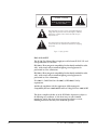
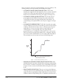
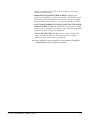
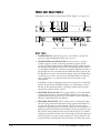
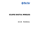
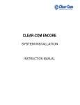
CLEAR-COM ENCORE
PS-702
TWO-CHANNEL POWER SUPPLY
INSTRUCTION MANUAL
PS-702 Two-Channel Power Supply Instruction Manual
© 2007 Vitec Group Communications Ltd. All rights reserved.
Part Number 810493Z Rev. 2
Vitec Group Communications, LLC.
850 Marina Village Parkway
Alameda, CA 94501
U.S.A
Vitec Group Communications
7400 Beach Drive
Cambridge Research Park
Cambridgeshire
United Kingdom
CB25 9TP
Vitec Group Communications
Room 1806, Hua Bin Building
No. 8 Yong An Dong Li
Jian Guo Men Wai Ave
Chao Yang District
Beijing, P.R. China 100022
® Clear-Com, CellCom/FreeSpeak and the Clear-Com Communication Systems logo are registered trademarks of The Vitec Group
plc.
CONTENTS
OPERATION . . . . . . . . . . . . . . . . . . . . . . . . . . . . . . . . . . . . . . . 1-1
Introduction . . . . . . . . . . . . . . . . . . . . . . . . . . . . . . . . . . . . . . . . . . . . . . . . . 1-1
Description . . . . . . . . . . . . . . . . . . . . . . . . . . . . . . . . . . . . . . . . . . . . . . . . . . 1-1
Fail Safe Power. . . . . . . . . . . . . . . . . . . . . . . . . . . . . . . . . . . . . . . . . . . . . . . . 1-1
Front and Rear Panels . . . . . . . . . . . . . . . . . . . . . . . . . . . . . . . . . . . . . . . . . . 1-4
Front Panel . . . . . . . . . . . . . . . . . . . . . . . . . . . . . . . . . . . . . . . . . . . . . . . . 1-4
Rear Panel . . . . . . . . . . . . . . . . . . . . . . . . . . . . . . . . . . . . . . . . . . . . . . . . . 1-5
INSTALLATION. . . . . . . . . . . . . . . . . . . . . . . . . . . . . . . . . . . . . . 2-1
Quick Start . . . . . . . . . . . . . . . . . . . . . . . . . . . . . . . . . . . . . . . . . . . . . . . . . . 2-1
Installation . . . . . . . . . . . . . . . . . . . . . . . . . . . . . . . . . . . . . . . . . . . . . . . . . . 2-1
Intercom Line Connection . . . . . . . . . . . . . . . . . . . . . . . . . . . . . . . . . . . . 2-1
Line Termination (Rear Panel). . . . . . . . . . . . . . . . . . . . . . . . . . . . . . . . . . 2-2
Program Input (Rear Panel) . . . . . . . . . . . . . . . . . . . . . . . . . . . . . . . . . . . . 2-2
Rack Mounting . . . . . . . . . . . . . . . . . . . . . . . . . . . . . . . . . . . . . . . . . . . . . 2-2
System Checkout. . . . . . . . . . . . . . . . . . . . . . . . . . . . . . . . . . . . . . . . . . . . 2-3
Check Termination . . . . . . . . . . . . . . . . . . . . . . . . . . . . . . . . . . . . . . . . 2-3
Check Intercom Cable Resistance . . . . . . . . . . . . . . . . . . . . . . . . . . . . . 2-3
Final Tests . . . . . . . . . . . . . . . . . . . . . . . . . . . . . . . . . . . . . . . . . . . . . . . . . 2-4
MAINTENANCE . . . . . . . . . . . . . . . . . . . . . . . . . . . . . . . . . . . . . 3-1
Introduction . . . . . . . . . . . . . . . . . . . . . . . . . . . . . . . . . . . . . . . . . . . . . . . . . 3-1
Troubleshooting Tips. . . . . . . . . . . . . . . . . . . . . . . . . . . . . . . . . . . . . . . . . . . 3-1
PS-702 Block Diagram . . . . . . . . . . . . . . . . . . . . . . . . . . . . . . . . . . . . . . . . . 3-3
TECHNICAL SPECIFICATIONS . . . . . . . . . . . . . . . . . . . . . . . . . . . . . . 4-1
PS-702 Two-Channel Power Supply . . . . . . . . . . . . . . . . . . . . . . . . . . . . . . . 4-1
GLOSSARY . . . . . . . . . . . . . . . . . . . . . . . . . . . . . . . . . . . . . . . . 5-1
LIMITED WARRANTY . . . . . . . . . . . . . . . . . . . . . . . . . . . . . . . . . . . 6-I
Warranty Period. . . . . . . . . . . . . . . . . . . . . . . . . . . . . . . . . . . . . . . . . . . . . . . 6-i
Technical Support . . . . . . . . . . . . . . . . . . . . . . . . . . . . . . . . . . . . . . . . . . . . . 6-i
Warranty Repairs and Returns . . . . . . . . . . . . . . . . . . . . . . . . . . . . . . . . . . . . 6-ii
Non-Warranty Repairs and Returns. . . . . . . . . . . . . . . . . . . . . . . . . . . . . . . . 6-ii
Extended Warranty . . . . . . . . . . . . . . . . . . . . . . . . . . . . . . . . . . . . . . . . . . . . 6-ii
Service Contract . . . . . . . . . . . . . . . . . . . . . . . . . . . . . . . . . . . . . . . . . . . . . 6-iii
Liability . . . . . . . . . . . . . . . . . . . . . . . . . . . . . . . . . . . . . . . . . . . . . . . . . . . . 6-iii
PS-702 TWO-CHANNEL POWER SUPPLY
i
ii
PS-702 TWO-CHANNEL POWER SUPPLY
IMPORTANT SAFETY INSTRUCTIONS
1.
2.
3.
4.
5.
6.
7.
Please read and follow these
instructions before operating
this product.
8.
9.
10.
11.
12.
13.
14.
15.
Read these instructions.
Keep these instructions.
Heed all warnings.
Follow all instructions.
Do not use this apparatus near water.
Clean only with dry cloth.
Do not block any ventilation openings. Install in accordance with the
manufacturer’s instructions.
Do not install near any heat sources such as radiators, heat registers, stoves,
or other apparatus (including amplifiers) that produce heat.
Do not defeat the safety purpose of the polarized or grounding-type plug. A
polarized plug has two blades, with one wider than the other. A
grounding-type plug has two blades and a third grounding prong. The wide
blade or the third prong are provided for your safety. If the provided plug
does not fit into your outlet, consult an electrician for replacement of the
obsolete outlet.
Protect the power cord from being walked on or pinched particularly at
plugs, convenience receptacles, and the point where they exit from the
apparatus.
Only use attachments/accessories specified by the manufacturer.
Use only with the cart, stand, tripod, bracket, or table specified by the
manufacturer, or sold with the apparatus. When a cart is used, use caution
when moving the cart/apparatus combination to avoid injury from tip-over.
Unplug this apparatus during lightning storms or when unused for long
periods of time.
Refer all servicing to qualified service personnel. Servicing is required when
the apparatus has been damaged in any way, such as power-supply cord or
plug is damaged, liquid has been spilled or objects have fallen into the
apparatus, the apparatus has been exposed to rain or moisture, does not
operate normally, or has been dropped.
WARNING: To reduce the risk of fire or electric shock, do not expose this
product to rain or moisture.
Please familiarize yourself with the safety symbols in Figure 1. When you see
these symbols on this product, they warn you of the potential danger of electric
shock if the main station is used improperly. They also refer you to important
operating and maintenance instructions in the manual.
PS-702 TWO-CHANNEL POWER SUPPLY
iii
CAUTION
RISK OF ELECTRIC SHOCK
DO NOT OPEN
This symbol alerts you to the presence of uninsulated dangerous
voltage within the product's enclosure that might be of sufficient
magnitude to constitute a risk of electric shock. Do not open
the product's case.
This symbol informs you that important operating and maintenance instructions are included in the literature accompanying
this product.
Figure 1: Safety Symbols
EMC AND SAFETY
The PS-702 Two-Channel Power Supply meets all relevant CE, FCC, UL, and
CSA specifications set out below:
EN55103-1 Electromagnetic compatibility. Product family standard for audio,
video, audio-visual, and entertainment lighting control apparatus for
professional use. Part 1: Emissions.
EN55103-2 Electromagnetic compatibility. Product family standard for audio,
video, audio-visual, and entertainment lighting control apparatus for
professional use. Part 2: Immunity.
UL 60065-7, CAN/CSA-C22.2 No.60065-3, IEC 60065-7 Safety
requirements.
And thereby compliance with the requirement of Electromagnetic
Compatibility Directive 2004/108/EC and Low Voltage Directive 2006/95/EC
This device complies with Part 15 of the FCC Rules. Operation is subject to
the following two conditions: (1) this device may not cause harmful
interference, and (2) this device must accept any interference received,
including interference that may cause undesired operation.
iv
PS-702 TWO-CHANNEL POWER SUPPLY
1
OPERATION
INTRODUCTION
Congratulations on choosing this Clear-Com product. Clear-Com was
established in 1968 and remains the market leader in providing intercoms for
entertainment, broadcast and industrial applications. The ruggedness and high
build-quality of Clear-Com products defines the industry standard. In fact, many
of our original beltpacks and main stations are still in daily use around the world.
The PS-702 power supply is a powerful, yet user-friendly unit that can serve as
the heart of a Clear-Com system.We recommend that you read through this
manual completely to better understand the functions of the PS-702 and how to
optimize your system setup.
Please pay particular attention to the section on system wiring, as improper
wiring detracts from the performance of the system or causes system failure. If
you encounter a situation or have a question that this manual does not address,
contact your dealer or call Clear-Com directly at the factory. Our applications
support and service people are standing by to assist you. (Refer to Chapter 6:
“Warranty” for contact information.) Thank you for selecting Clear-Com for
your communications needs.
DESCRIPTION
The Clear-Com PS-702 is a single-rack-space, one- or two-channel intercom
power supply which can provide 1.2 ampere (2 amperes peak during call signals
and other temporary events) per channel to operate Clear-Com beltpacks and
remote stations. This power is supplied to either or both channels, and will
support up to 40 beltpacks or 10 speaker stations. Clear-Com’s advanced fail-safe
design can sense the difference between a short or an overload to optimally
protect itself. Power is restored in as little as 0.5 seconds, depending upon
whether there was a single or multiple short or overload. The other channel
continues to operate normally. The PS-702’s advanced fail-safe circuit will bring
the power back up even under full load conditions. LED indicators signal a fault
on either channel. A line-level program input offers a master input level.
Individual program selects, each with its own send level, are provided for each
channel. Use of a switching power supply allows the PS-702 to operate with any
AC line voltage from 100 to 240 volts AC at 50 or 60 Hz. The sturdy metal
chassis and extra-thick front panel with integral rack ears maintains legendary
Clear-Com ruggedness.
FAIL SAFE POWER
An intercom power supply has special needs that are not met by traditionally
designed power supplies. An intercom power supply must work in adverse
conditions such as low AC line voltage, momentary shorts on the DC power
PS-702 TWO-CHANNEL POWER SUPPLY
1-1
lines to the stations, and excessive peak loads during “power-on”conditions. The
following features are incorporated into the PS-702’s power supply:
•
AUTOMATIC SHORT CIRCUIT PROTECTION: The PS-702’s
internal power supply checks each channel for a short or current overload. If
it detects a short the power supply will shut down that channel. A short
duration short circuit will not cause the power supply to interrupt power.
•
AUTOMATIC OVERLOAD PROTECTION: The PS-702’s internal
power supply senses the difference between shorts and overloads. If an
overload is detected the power supply will shut down that channel. An
overload lasting a short period will not cause the power supply to interrupt
power.
•
AUTOMATIC POWER RESTORE: The PS-702’s internal power supply
senses the difference between short-term and long-term shorts and overload
conditions. After the first few times a short or overload occurs, the power
supply will try to restore power after only 0.5 seconds. If the short or
overload persists or occurs repeatedly, the power supply will take
progressively longer (to a maximum of 20 seconds) to try to restore power.
This protects the power supply from damage due to overheating. Once the
short is removed, the channel will recover, even under a full load condition.
The automatic power restore times are shown in the following chart:
20
20
14
15
Numberof
secondsto
restore
10
7
5
4
2
0.5
0
0 1 2 3 4 5 6 7 8 9 10 11 12 13 14 15 16 17 18 19 20
Numberofrecentshortsoroverloads
Figure 1-1: Automatic Power Restore Times
1-2
•
INDIVIDUAL CHANNEL SHORT CIRCUIT PROTECTION: Each
individual channel is separately overload and short circuit protected and may
draw as much as 1.2 amperes, though the total to both channels is limited to
2 amperes. A short on any one intercom line will not bring the whole system
down.
•
FRONT PANEL INDICATIONS: There are two short/overload indicators
on the front panel (one for each channel) and a power indicator for the power
supply. The short/overload indicators light steady when an overload or short
condition is detected. They blink if power to a channel has been shut off as a
PS-702 TWO-CHANNEL POWER SUPPLY
result of an overload or short. There is also an indicator to show when
channels A and B are linked.
•
PARALLELING MULTIPLE POWER SUPPLIES: Multiple power
supplies can be paralleled to increase system capacity. The PS-702’s internal
power supply will automatically detect the actions of other power supplies
during overloads and short circuits to restore power as quickly as possible.
•
MULTI-CHANNEL REMOTE STATIONS MAINTAIN THE POWER
LINE ISOLATION: The RM-702 and KB-702 as well as any two-channel
remote stations or beltpacks are designed to use the isolated power provided
by the PS-702. Refer to Chapter 2‚ “Installation.”
•
LOW NOISE CIRCUITRY: The direct current outputs of the PS-702
contain very little hum and noise. The PS-702 does not contribute to
audible noise in the remote stations and beltpacks.
Note: Power supply lines connected together at remote stations will disable the
individual channel short circuit protection feature.
PS-702 TWO-CHANNEL POWER SUPPLY
1-3
FRONT AND REAR PANELS
A description of the connectors and controls follows (Figure 1-2 on page 1-4).
7
4
3
2
6
4
3
2
5
1
TERM
A
OFF
PS-702
12
CHANNEL A
11
TERM
B
OFF
ON
PROGRAM INPUT
CHANNEL B
10
11
LEVEL
ADJUST
ON
10
8
9
Figure 1-2: Front and Read Panels
FRONT PANEL
1. POWER SWITCH: Turns the AC power to the PS-702 on and off. The
green power light will illuminate when the power is on.
2. SHORT/OVERLOAD INDICATORS: If a short circuit or overload
condition appears on either of the intercom channel outputs, the red
short/overload light for that channel will illuminate. If this condition persists,
the microprocessor will disconnect power to that channel and the red short
/overload light will blink. If a red short/overload light is blinking, the fault on
that channel must be located and removed. When the fault is removed, the
PS-702 will restore power to that channel and the short/overload light will go
out. If there are no shorts, but the short/overload light blinks, an overload
exists, possibly due to too many intercom stations connected on that
intercom line.
If the failure continues, unplug the intercom line connected to the affected
channel. Its red short/overload light should go out. This indicates a short in
that line. Follow that intercom line, connecting and disconnecting cables
along the line until the fault is isolated.
3. PROGRAM SEND ON/OFF: These toggle switches, one for each channel,
connect program audio to each channel. Both channels receive the same
signal from the rear panel program input. The number of active sends will not
affect the overall send level to any channel.
4. PROGRAM SEND LEVEL: These controls (one for each channel) adjust
the level of program heard in that channel. The program switch must be on
for the control to function on that channel. (The level controls work in
conjunction with the program trim (8) level control on the rear panel.) For a
higher program level, turn the control clockwise. For less program level, turn
the control counter-clockwise. If the control is all the way up on a channel
and the program level in the line is not loud enough, increase the input level
with the program trim control on the rear panel. Conversely, if there is still
program heard on a channel when its level is all the way down, decrease the
1-4
PS-702 TWO-CHANNEL POWER SUPPLY
program trim level. Any change in the program trim level control on the rear
panel to adjust for one channel will necessitate adjustments on the other
channel to compensate.
Note:
Do not force the controls past their stop points as this will damage
them.
5. TEST TONE: This toggle switch turns on a test tone which can be heard on
either or both channels when the program send switch for that channel is in
the off position. It can be handy for identifying which intercom channel is
which or for other test purposes. The program send level controls adjust the
level of the test tone on each channel.
6. A+B LINK SWITCH and INDICATOR: This toggle switch links the audio
for channels A and B together. A yellow light indicates when the channels are
linked. It can be useful to have both channels linked for rehearsals, but
separated for performances.
7. INTERCOM LINE CONNECTOR and SWITCH: A single intercom line
connector is located on the front panel for convenience. It can be switched
between channels A and B with the associated toggle switch.
REAR PANEL
8. PROGRAM INPUT: This three-pin female XLR jack accepts a balanced or
unbalanced line-level signal. This is typically a feed from a mixing console,
an air feed from a studio to remote site over a phone line, or an audio cue
track. Send levels to the individual channels are controlled with a
combination of the program trim level and the program send levels on the
channels. This feed can be fed to either or both intercom lines.
9. AUDIO ADJUST: This control adjusts the overall input level of the external
program coming into the PS-702. It is used with the program send level
controls to achieve desired system program levels. Turn the control clockwise
to increase the gain and counter-clockwise to reduce it.
Note:
Do not force this control past its stop points as this will damage it.
10. TERM. ON/OFF: These switches (one per channel) select whether the
PS-702 will provide the required termination for each channel. These should
always be on unless there are other power supplies or terminated main
stations in the system. If there are other possible terminations in the system,
all but one must be turned off.
11. INTERCOM LINE CONNECTORS: There are three 3-pin male XLR
jacks per channel, wired in parallel, or looped through. All the stations in the
system are ultimately connected to the PS-702 through these jacks. Because
intercom audio is bidirectional, they are neither inputs nor outputs, but may
be thought of as “ports.” Pin #1 is connected to the shield and carries the
signal ground. Pin #2 carries the DC voltage that runs the remote stations.
Pin #3 carries two way audio and call signals.
12. AC POWER SUPPLY INPUT: Connects to AC with an IEC cable. The
PS-702 will accept any line voltage between 100 and 240 volts AC at
50 to 60 Hz. It will automatically adjust to the line voltage. There is no need
for a selector switch or an external fuse.
PS-702 TWO-CHANNEL POWER SUPPLY
1-5
1-6
PS-702 TWO-CHANNEL POWER SUPPLY
2
INSTALLATION
QUICK START
1. Unpack the unit and inspect for any damage that may have occurred during
shipping.
2. Connect the proper AC mains cable to the outlet on the rear panel.
3. Install the PS-702.
4. Connect the intercom lines and program input as required. Connect the AC
cord to the mains circuit.
5. Set the two termination switches on the rear panel to on.
6. Switch the power on. The green power light should be on and the two red
short/overload lights should be off.
7. Switch the test tone and A+B link switches off. The yellow A+B link light
should be off.
8. Select program sends and set program levels as required using program trim
and program send level controls.
9. Set levels and sidetone nulls at remote stations.
10. The intercom system should now be operating properly.
11. Read the rest of this manual for further information.
INSTALLATION
INTERCOM LINE CONNECTION
The PS-702 provides three rear-panel 3-pin male XLR connectors for each
intercom line. These connectors are wired in parallel and intended for
loop-through connection. Any single-channel station or channel of a
multi-channel station connected on a line plugged into Channel A of the PS-702
will be “party-lined” with all the other stations on that same channel. In a
multi-channel system, the goal is to assign specific people to the correct group,
(i.e., the other people with whom they need to be in contact the most). This is
particularly important when party-line users are on a single-channel beltpack or
station; less so if they are on multi-channel stations. The pinout of the intercom
connectors is as follows:
Pin 1 --- Ground (shield)
Pin 2 --- Power
Pin 3 --- Audio
PS-702 TWO-CHANNEL POWER SUPPLY
2-1
LINE TERMINATION (REAR PANEL)
Switching of the channels’ terminations on and off is done with the rear-panel
toggle switches. In most systems, all terminations on the PS-702 should be in the
on position (default setting). The fundamental concept of Clear-Com party-line
intercom is that all channels are terminated in one location, preferably at the
power supply.
Caution: All intercom lines must be terminated. Care must be taken not to
“double-terminate” a line. All unused intercom lines must also be
terminated.
The PS-702 provides terminations for each of its two channels. Clear-Com main
stations and power supplies provide switch-selectable termination networks on all
intercom lines. It is up to the user to ensure that the terminations are set
correctly. An unterminated line will cause excessive levels, possible oscillation of
line drivers, and severe imbalance of hybrid null networks. A line with double or
multiple terminations will cause low levels and severe imbalance of hybrid null
circuits.
If the PS-702 is the only power supply in the system (no other power supplies or
powered main stations are in the system) the termination switch on each channel
of the PS-702 should be switched to on. Simply toggle the rear-panel switch
labeled term to the on position. The termination switch should be set to the off
position only if the channel is terminated at another station.
PROGRAM INPUT (REAR PANEL)
An XLR connector provides the main program input to the station. This input
level is controlled by the rear-panel program trim control adjacent to the program
input connector. This control sets the overall level for all of the channels. The
input accepts a balanced or unbalanced line-level audio signal. The program can
be fed to either or both of the intercom lines by using the front-panel toggle
switches labeled program on/off. There is one of these switches for each channel.
The pinout of the program input connector is as follows:
Pin 1--- Ground (shield)
Pin 2 --- - Signal
Pin 3--- +Signal
RACK MOUNTING
The unit requires 1.75 in. (4.45 cm or 1RU) of rack space. It requires no
additional free rack space above or below it for ventilation. The station is 5.25 in.
(13.34 cm) in depth and requires at least 2.5 in. (6.35 cm) clearance in the rear
for connectors and cables. The single-piece front panel has integral “rack ears.”
This adds stability and strength.
2-2
PS-702 TWO-CHANNEL POWER SUPPLY
SYSTEM CHECKOUT
Before you turn on the power:
Check Termination
There should be one and only one termination for each channel in the system.
This termination is usually set to on at the main station or power supply. To
ascertain that only one termination is present on the channel, perform the
following test:
1. Using a multimeter, measure the resistance between pins #1 and #3 on one
of the Channel A XLR connectors at the rear of the unit.
2. If the channel is terminated properly, then the resistance should measure
approximately 4 kOhm. A very high channel resistance means the channel is
not terminated. Channel resistance of 2 kOhm indicates a
double-termination. If a double-termination is indicated, locate the other
power supply or main station and set its termination to off.
Note:
The location of the termination switch varies with model. On some
products, the termination switches are on the rear panel; on others they
are inside the unit. Consult the unit’s manual for the location.
3. Repeat for the other channels.
4. Check resistance between chassis ground and pin #1. Using an ohmmeter,
measure the resistance from pin #1 on the main station or power supply to
chassis ground. The measurement should read 10 Ohms. A high reading
(over 100 Ohms) indicates that the 10 Ohm resistor in the unit has failed
and requires replacement. Failure to perform the replacement will result in
an audible “buzz” in the system. A reading of less than 10 Ohms (or a short)
typically indicates that the shell and pin #1 of one of the interconnect cables
are shorted together. Test the individual cables until the culprit is located and
repair or replace the cable.
Note:
Pin #1 and the shell of the XLR plug on the interconnect cables should
NOT be connected together.
Check Intercom Cable Resistance
For minimal crosstalk, the ground resistance of the intercom cables should be as
low as possible, preferably less than 2 Ohms. Disconnect an intercom line from
the main station or power supply. At the point in the intercom line furthest from
the unit, connect a clip lead jumper between pins #1 and #2. Back at the
“powered” end, use an ohmmeter to measure the resistance between pins #1 and
#2. A value of less than 4 Ohms is ideal.
PS-702 TWO-CHANNEL POWER SUPPLY
2-3
FINAL TESTS
After you turn the power on:
1. Check for proper voltage on pin #2 of any intercom line or jack in a channel.
It should read 26 - 30 volts.
2. Test for proper operation of call signaling. Activate the call signal on any belt
pack or station. The call lights on all other stations on that channel should
illuminate and then go out when the call button is released.
3. Adjust the sidetone null on all stations. (Refer to the manual for each specific
unit for instructions.)
2-4
PS-702 TWO-CHANNEL POWER SUPPLY
3
MAINTENANCE
INTRODUCTION
This chapter provides maintenance information including troubleshooting tips and a block diagram.
Caution:These servicing instructions are for use by qualified personnel only. To reduce the risk of electrical shock, do not
perform any servicing other than that contained in the operating instructions unless you are qualified to do so.
TROUBLESHOOTING TIPS
SYMPTOM
System does not operate. No
power to the PS-702. Green
power light is not illuminated
and no short/overload lights are
illuminated
Red short/overload light
illuminated
Both red short/overload lights are
illuminated
Hum or buzz in system
CAUSE
SOLUTION
No AC power to the PS-702.
Check AC connection and cable. Plug
into dependable AC source.
PS-702 has an internal power supply
failure.
Unit requires servicing.
Short or overload on that channel due
to a shorted or mis-wired cable.
Remove cables one at a time from
system until the faulty line is located.
Check for shorts between pins #1 and
#2. Once the short is removed, the
PS-702 will reset automatically and
the power will come back up within
several seconds, depending upon how
long the short has been present.
Defective remote station.
Check remote station and replace if
necessary.
System is overloaded.
Remove cables one at a time from
system to help determine where the
excess current requirements lie.
Re-evaluate system current needs.
Short in multipair cable.
Remove cables one at a time from
system until the faulty line is located.
Check for shorts between pins #1
and #2.
Inductive pickup caused by close
proximity of main or remote stations
to power lines or transformers.
Relocate offending unit.
PS-702 TWO-CHANNEL POWER SUPPLY
3-1
SYMPTOM
CAUSE
SOLUTION
10Ω chassis ground resistor is open.
Check the DC resistance for 10Ω
between the chassis and pin #1 of any
intercom connector.
If this condition occurs, it is because the system ground came into contact with something that was hot with
respect to the power supply earth ground. If this occurs, carefully check the system ground and AC distribution
in the area.
This is a potentially dangerous situation. A shock hazard may exist between the metal boom of a remote station
headset and ground.
System feedback (acoustical)
Volume control at the remote station
is set too high.
Adjust.
Channel unterminated.
Set the PS-702 termination switch for
that channel to the on position.
A headset extension cord was used.
Headset extension cords are not
recommended.
440 Hz tone is present on either
or both channels
Test tone feature is on.
Set the test tone switch to the off
position.
Excessive crosstalk
High DC resistance in ground return.
Use heavier cable; add additional
conductor(s) to ground return.
Multi-channel cable pairs are not
individually shielded.
Replace cable with individually
shielded pairs.
Headset cables are not wired properly
or shielded properly.
Correct wiring. Use headsets with
properly shielded wiring.
Overload of program in circuit.
Reduce program in level or reduce the
gain of the program signal at the
source, such as an audio mixer.
Program signal sounds distorted
Table 3-1: Troubleshooting Tips
3-2
PS-702 TWO-CHANNEL POWER SUPPLY
PS-702 BLOCK DIAGRAM
The following is a block diagram of the PS-702:
PS-702
On/Off
IEC
P ower
Inlet
S witching
P ower S upply
Module
Voltage
Regulator
Channel A
Power
Controller
Channel A
Current
Sensor
T es t
J ack
C hannel A – B
S elect
Channel B
Power
Controller
Channel A
Voltage
Sensor
Overload Overload
C hannel C hannel
A
B
Channel B
Current
Sensor
C hannel
A
Channel B
Voltage
Sensor
Microproces s or
Power
T es t T one
On / Off
440 Hz
A
Filter
Program
Trim
C hannel
B
S end
Levels
B
A
P rogram
On / Off
Program
Input
B
Ch A
Term
Ch B
Term
A+B
Link
Figure 3-3: PS-702 Block Diagram
PS-702 TWO-CHANNEL POWER SUPPLY
3-3
3-4
PS-702 TWO-CHANNEL POWER SUPPLY
4
TECHNICAL SPECIFICATIONS
PS-702 TWO-CHANNEL POWER SUPPLY
dBu is an absolute measurement. 0 dBu is referenced to 0.775 volts RMS
Program Line Input
Maximum Level before Clipping
Input Impedance
Frequency Response
Program Input - Party Line
Max Distortion
Program Input - Party Line
Noise
Program Mic Input - Party Line
Max Gain
Program Input - Party Line
Min Gain
Program Input - Party Line
>= 20dBu
>= 5KΩ
200 - 20KHz ± 3dB
<= 0.2%
< -70dBu
>= -16dB
<= -20dB
Mains Power
Input Voltage Range
Input Frequency Range
Input Power
Output Voltage
Output Current per Channel (Continuous)
Output Current per Channel (Peak)
100 - 240 VAC
50 - 60 Hz
<= 60 VAC
30 VDC ± 0.5V
1.2 A
2 A (Do not exceed the 1.2A rating
for more than 2 seconds per 1
minute period)
Short Circuit Recovery Time (1st short)
<= 0.5 sec
Short Circuit Recovery Time >= 20 shorts in 20sec) <= 20 sec
Station Capacity
Rear Panel Connectors
Intercom:
Program:
PS-702 TWO-CHANNEL POWER SUPPLY
Up to 40 RS-601 beltpacks or 10
speaker stations or 12 headset
stations distributed over both
channels
(6) XLR-3M (3 per channel)
(1) XLR-3F
4-1
AC Power:
Rear Panel Controls
Front Panel Connectors
Intercom
Front Panel Controls & Indicators
Environmental
Dimensions
Weight
IEC 320 connector
(2) Termination On-Off
switches
(1) Volume control
(1) XLR-3M
(1) Intercom channel switch
(1) A+B link switch
(2) Program switch
(2) Send level controls
(1) Test tone switch
(2) Overload LEDs
(1) Link indicator LED
(1) Power indicator LED
(1) Power switch
32 - 122o F (0 - 50o C)
19 in. W x 1.75 in. H x 7.5 in. D
(483 mm x 44 mm x 190 mm)
6.16 lbs. (2.80 kg)
Notice About Specifications
While Clear-Com makes every attempt to maintain the accuracy of the
information contained in its product manuals, that information is subject to
change without notice. Performance specifications included in this manual are
design-center specifications and are included for customer guidance and to
facilitate system installation. Actual operating performance may vary.
4-2
PS-702 TWO-CHANNEL POWER SUPPLY
5
GLOSSARY
Some of the terms used when discussing critical communications for television or
theatre may be new to you as they are unique to intercom applications. Although
many of the terms are common to other audio applications, to be certain you
understand their meanings we offer the following definitions:
All Call: Ability to push one button from the main station and talk to all
channels at once on a multiple channel system.
Ambient Noise: Those background sounds which are not part of the specific
communication but are picked up by the microphone. Selection of a good
“noise-cancelling” mic will reduce ambient noise.
Beltpack: A portable electronics package worn on the belt or mounted on a wall
or other convenient location. Interconnects to system with mic cable and is
powered by a central power supply or main station.
Bridging, High Impedance (hi-Z): A method of connecting to an audio line
(such as Clear-Com) without loading or taking appreciable power from that line.
Simply stated, as you add more and more stations to the line, the volume remains
constant.
Call Signaling: This feature is included with the majority of Clear-Com
products. It is a visual indicator on a station (lamp or LED) used to attract the
attention of an operator who has removed the headset.
Channel: A channel is the line that connects parties together within a party line;
it is a two-way talk path. For example, if you have six people who need to hear
one director, you have a seven-station single-channel need. If the same director
needs to speak privately to any one of the six, add a second channel. You now
have a seven-station, two-channel system.
Closed-Circuit: Any intercom which is connected via cable (also called
hard-wired).
Cross Talk: Leakage of audio transmissions from one channel to another.
Dry Pair: A telephone term used to describe a pair of wires (two conductors) that
carry audio but no DC voltage. Contrast this with a “wet pair” that carries both
audio and voltage.
Duplex: Duplex refers to bidirectional communications. Normal
communication between individual talking face-to-face is “full duplex” - in other
words you can talk and listen simultaneously. The other alternative is
“half-duplex” such as a push-to-talk situation where one station at a time can talk
while others listen. A walkie-talkie is a good example of half-duplex
communication.
IFB: The term means “Interrupted Fold Back.” A fold-back is a monitor system
that allows, for example, talent to hear their voices, or musicians to hear their
PS-702 TWO-CHANNEL POWER SUPPLY
5-1
voices and instruments on stage. IFB (program interrupt) disconnects the
program audio source while the talk button on the main station is pushed.
ISO: A private conversation path. An ISO channel allows one to simply push a
button and transfer themselves and the person they wish to speak with to an
isolated channel.
Linking: Linking ties separate channels into one single party line.
Main Station: This is a product that includes both the ability to communicate
with multiple channels (without connecting them together) and to power all the
stations connected to these channels.
Master Station: A remote station which needs AC power to operate.
Multi-Channel: More than one channel.
Party Line (P.L.): Intercom system where all people talking on the system can
talk or listen to each other simultaneously. Also called conferencing.
Point to Point: One path to one person.
Program: Audio source that is fed into the intercom channels.
Program Interrupt: Disconnects the audio source while the talk button on the
main station is pushed (IFB).
Remote Mic Kill (RMK): The ability for certain main stations to shut off all
microphones on beltpacks in a system.
Remote Station: Like the beltpack, this would be any of the products connected
to the intercom line that allow duplex or half-duplex conversation, but do not
contain a power supply.
Sidetone: This is your own voice heard in your earphone as you are speaking.
Stage Announce (SA): Redirects output of the main station’s microphone to an
external destination (such as a PA system).
Station: A station is connected to one or more channels. For example, if you have
six people who need to hear one director, you have a seven-station single-channel
need. If the same director needs to speak privately to any one of the six, add a
second channel. You now have a seven-station, two-channel system.
Termination: Passive network that is connected in each channel, usually on the
power supply or main station.
5-2
PS-702 TWO-CHANNEL POWER SUPPLY
LIMITED WARRANTY
Vitec Group Communications (VGC) warrants that at the time of purchase, the
equipment supplied complies with any specification in the order confirmation
when used under normal conditions, and is free from defects in workmanship
and materials during the warranty period.
VGC offers 24 x 7 customer
support if you have an
Extended Warranty or
Service Contract.
Return Material
Authorization (RMA)
numbers are required for all
returns.
Both warranty and
non-warranty repairs are
available.
During the warranty period VGC, or any service company authorized by VGC,
will in a commercially reasonable time remedy defects in materials, design, and
workmanship free of charge by repairing, or should VGC in its discretion deem it
necessary, replacing the product in accordance with this limited warranty. In no
event will VGC be responsible for incidental, consequential, or special loss or
damage, however caused.
WARRANTY PERIOD
The product may consist of several parts, each covered by a different warranty
period. The warranty periods are:
• Cables, accessories, components, and consumable items have a limited
warranty of 90 days.
• Headsets, handsets, microphones, and spare parts have a limited warranty of
one year.
• UHF wireless IFB products have a limited warranty of one year.
• UHF wireless intercom systems have a limited warranty of three years.
• All other Clear-Com and Drake brand systems and products, including
beltpacks, have a limited warranty of two years.
The warranty starts at the time of the product’s original purchase. The warranty
start date for contracts which include installation and commissioning will
commence from the earlier of date of the Site Acceptance Test or three months
from purchase.
TECHNICAL SUPPORT
To ensure complete and timely support to its customers, VGC’s User Support
Center is staffed by qualified technical personnel. Telephone and email technical
support is offered worldwide by the User Support Center.
The User Support Center is available to VGC’s customers during the full course
of their warranty period. Telephone support during the warranty period will be
offered at no charge between 09:00 and 17:00 according to the customer’s local
time zone.
In addition, for customers who purchase an Extended Warranty or Service
Contract, 24-hour customer support is offered immediately upon purchase of
WARRANTY
i
such agreement. For more information, contact your authorized dealer,
distributor, or sales representative.
Instructions for reaching VGC’s User Support Centers are given below.
Telephone for Europe, Middle East and Africa: +49 40 6688 4040
Telephone for the Americas and Asia: +1 510 337 6600
Email: [email protected]
Once the standard warranty period has expired, the User Support Center will
continue to provide telephone support if you have purchased an Extended
Warranty or Service Contract. In these cases, you will have access to telephone
support 24 hours per day, 7 days per week.
WARRANTY REPAIRS AND RETURNS
Before returning equipment for repair, contact a User Support Center to obtain a
Return Material Authorization (RMA). VGC representatives will give you
instructions and addresses for returning your equipment. You must ship the
equipment at your expense, and the support center will return the equipment at
VGC’s expense.
For out-of-box failures, use the following contact information:
Europe, Middle East and Africa
Tel: +44 1223 815000 Email: [email protected]
North America, Canada, Mexico, Caribbean & US Military
Tel: +1 510 337 6600 Email: [email protected]
Asia Pacific & South America
Tel: +1 510 337 6600 Email: [email protected]
VGC has the right to inspect the equipment and/or installation or relevant
packaging.
NON-WARRANTY REPAIRS AND RETURNS
For items not under warranty, you must obtain an RMA by contacting the User
Support Center. VGC representatives will give you instructions and addresses for
returning your equipment.
You must pay all charges to have the equipment shipped to the support center
and returned to you, in addition to the costs of the repair.
EXTENDED WARRANTY
If you purchase an Extended Warranty, you are also given access free of charge to
the User Support Center 24 hours a day, 7 days a week.
You can purchase an extended warranty at any time during the first two years of
ownership of the product. The purchase of an extended warranty extends to five
ii
WARRANTY
years the warranty of any product offered with a standard two-year warranty.
The total warranty period will not extend beyond five years. Any purchase of an
extended warranty provides 24 x 7 customer support in addition to the warranty
immediately upon purchase of the warranty extension.
Note: VGC does not offer warranty extensions on UHF wireless intercom
systems, or on any product with a 1-year or 90-day warranty.
SERVICE CONTRACT
VGC also offers service contracts that provide 24 x 7 telephone support, advance
replacements, training, proactive maintenance, on-site visits, and no charge for
repair or replacement of equipment. For more information, contact your
authorized dealer, distributor, or sales representative.
LIABILITY
THE FOREGOING WARRANTY IS VGC'S SOLE AND EXCLUSIVE
WARRANTY. THE IMPLIED WARRANTY OF MERCHANTABILITY
AND FITNESS FOR A PARTICULAR PURPOSE AND ANY OTHER
REQUIRED IMPLIED WARRANTY SHALL EXPIRE AT THE END OF
THE WARRANTY PERIOD. THERE ARE NO OTHER WARRANTIES
(INCLUDING WITHOUT LIMITATION WARRANTIES FOR
CONSUMABLES AND OTHER SUPPLIES) OF ANY NATURE
WHATSOEVER, WHETHER ARISING IN CONTRACT, TORT,
NEGLIGENCE OF ANY DEGREE, STRICT LIABILITY OR OTHERWISE,
WITH RESPECT TO THE PRODUCTS OR ANY PART THEREOF
DELIVERED HEREUNDER, OR FOR ANY DAMAGES AND/OR LOSSES
(INCLUDING LOSS OF USE, REVENUE, AND/OR PROFITS). SOME
STATES DO NOT ALLOW THE EXCLUSION OR LIMITATION OF
INCIDENTAL OR CONSEQUENTIAL DAMAGES OR THE
LIMITATION ON HOW LONG AN IMPLIED WARRANTY LASTS, SO
THE ABOVE LIMITATIONS MAY NOT APPLY TO YOU. IN ANY
EVENT, TO THE MAXIMUM EXTENT PERMITTED UNDER
APPLICABLE LAW, VGC'S LIABILITY TO CUSTOMER HEREUNDER
SHALL NOT UNDER ANY CIRCUMSTANCES EXCEED THE COST OF
REPAIRING OR REPLACING ANY PART(S) FOUND TO BE
DEFECTIVE WITHIN THE WARRANTY PERIOD AS AFORESAID.
This warranty does not cover any damage to a product resulting from cause other
than part defect and malfunction. The VGC warranty does not cover any defect,
malfunction, or failure caused beyond the control of VGC, including
unreasonable or negligent operation, abuse, accident, failure to follow
instructions in the manual, defective or improperly associated equipment,
attempts at modification and repair not approved by VGC, and shipping
damage. Products with their serial numbers removed or defaced are not covered
by this warranty.
This warranty does not include defects arising from installation (when not
performed by VGC), lightning, power outages and fluctuations, air conditioning
failure, improper integration with non-approved components, defects or failures
WARRANTY
iii
of customer furnished components resulting in damage to VGC provided
product.
This limited warranty is not transferable and cannot be enforced by anyone other
than the original consumer purchaser.
This warranty gives you specific legal rights and you may have other rights which
vary from country to country.
iv
WARRANTY