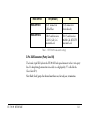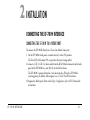
1
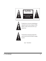
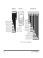
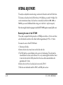
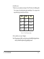
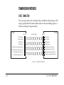
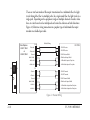
CLEAR-COM ENCORE
EF-701M
INTERFACE
INSTRUCTION MANUAL
EF-701M Interface Instruction Manual
© 2007 Vitec Group Communications. All rights reserved.
Part Number 810363Z Rev. 1
Vitec Group Communications, LLC.
850 Marina Village Parkway
Alameda, CA 94501
U.S.A
Vitec Group Communications
7400 Beach Drive
Cambridge Research Park
Cambridgeshire
United Kingdom
CB25 9TP
Vitec Group Communications
Room 1806, Hua Bin Building
No. 8 Yong An Dong Li
Jian Guo Men Wai Ave
Chao Yang District
Beijing, P.R. China 100022
Clear-Com, CellCom/FreeSpeak and the Clear-Com Communication Systems logo are registered trademarks of The Vitec Group plc.
CONTENTS
OPERATION . . . . . . . . . . . . . . . . . . . . . . . . . . . . . . . . . . . . . . . 1-1
Introduction . . . . . . . . . . . . . . . . . . . . . . . . . . . . . . . . . . . . . . . . . . . . . . . . . 1-1
Description. . . . . . . . . . . . . . . . . . . . . . . . . . . . . . . . . . . . . . . . . . . . . . . . . . 1-2
Connecting a Party-Line Channel to a Matrix Frame Port . . . . . . . . . . . . 1-2
Converting a Party-Line Channel to 4-Wire Audio. . . . . . . . . . . . . . . . . . 1-3
Front Panel Controls . . . . . . . . . . . . . . . . . . . . . . . . . . . . . . . . . . . . . . . . . . 1-8
Rear Panel Settings and Connectors . . . . . . . . . . . . . . . . . . . . . . . . . . . . . . 1-10
Mode-Switch Settings. . . . . . . . . . . . . . . . . . . . . . . . . . . . . . . . . . . . . 1-10
3-Pin XLR Connector (Party Line I/O) . . . . . . . . . . . . . . . . . . . . . . . 1-11
DB-15 Connector. . . . . . . . . . . . . . . . . . . . . . . . . . . . . . . . . . . . . . . . 1-12
RJ-45 Connector . . . . . . . . . . . . . . . . . . . . . . . . . . . . . . . . . . . . . . . . 1-12
EF-701M INTERFACE
i
INSTALLATION. . . . . . . . . . . . . . . . . . . . . . . . . . . . . . . . . . . . . . 2-1
Connecting the EF-701M Interface . . . . . . . . . . . . . . . . . . . . . . . . . . . . . . . 2-1
Connecting the EF-701M to a Matrix Port. . . . . . . . . . . . . . . . . . . . . . . . 2-1
Connecting the EF-701M to a Modem . . . . . . . . . . . . . . . . . . . . . . . . . . 2-2
Connecting the EF-701M to RTS-TW Equipment . . . . . . . . . . . . . . . . . 2-5
Other Connections . . . . . . . . . . . . . . . . . . . . . . . . . . . . . . . . . . . . . . . . . . 2-5
Levels . . . . . . . . . . . . . . . . . . . . . . . . . . . . . . . . . . . . . . . . . . . . . . . . . . . . . . 2-6
Nulling . . . . . . . . . . . . . . . . . . . . . . . . . . . . . . . . . . . . . . . . . . . . . . . . . . . . . 2-7
Adjusting the Null . . . . . . . . . . . . . . . . . . . . . . . . . . . . . . . . . . . . . . . . 2-8
Troubleshooting Tips for Nulling. . . . . . . . . . . . . . . . . . . . . . . . . . . . . 2-9
Internal Adjustments . . . . . . . . . . . . . . . . . . . . . . . . . . . . . . . . . . . . . . . . . 2-10
Removing the cover of the EF-701M . . . . . . . . . . . . . . . . . . . . . . . . . 2-10
Transmission methods . . . . . . . . . . . . . . . . . . . . . . . . . . . . . . . . . . . . . . . . 2-12
Direct Connection . . . . . . . . . . . . . . . . . . . . . . . . . . . . . . . . . . . . . . . . . 2-12
Fiber-Optic. . . . . . . . . . . . . . . . . . . . . . . . . . . . . . . . . . . . . . . . . . . . . . . 2-13
Other Methods . . . . . . . . . . . . . . . . . . . . . . . . . . . . . . . . . . . . . . . . . . . . 2-15
MAINTENANCE . . . . . . . . . . . . . . . . . . . . . . . . . . . . . . . . . . . . . 3-1
Troubleshooting Tips . . . . . . . . . . . . . . . . . . . . . . . . . . . . . . . . . . . . . . . . 3-1
Audio Troubleshooting Tips. . . . . . . . . . . . . . . . . . . . . . . . . . . . . . . . . 3-2
ii
EF-701M INTERFACE
Data Troubleshooting Tips. . . . . . . . . . . . . . . . . . . . . . . . . . . . . . . . . . 3-4
Nulling Troubleshooting Tips . . . . . . . . . . . . . . . . . . . . . . . . . . . . . . . 3-6
Block Diagram . . . . . . . . . . . . . . . . . . . . . . . . . . . . . . . . . . . . . . . . . . . 3-8
GLOSSARY . . . . . . . . . . . . . . . . . . . . . . . . . . . . . . . . . . . . . . . . 4-1
SPECIFICATIONS. . . . . . . . . . . . . . . . . . . . . . . . . . . . . . . . . . . . . 5-1
EF-701M technical Specifications. . . . . . . . . . . . . . . . . . . . . . . . . . . . . . . . .
Clear-Com Format . . . . . . . . . . . . . . . . . . . . . . . . . . . . . . . . . . . . . . . . . .
RTS format. . . . . . . . . . . . . . . . . . . . . . . . . . . . . . . . . . . . . . . . . . . . . . . .
General Characteristics . . . . . . . . . . . . . . . . . . . . . . . . . . . . . . . . . . . . . . .
5-1
5-1
5-1
5-1
LIMITED WARRANTY . . . . . . . . . . . . . . . . . . . . . . . . . . . . . . . . . . . 6-I
Warranty Period . . . . . . . . . . . . . . . . . . . . . . . . . . . . . . . . . . . . . . . . . . . . . . . 6-i
Technical Support. . . . . . . . . . . . . . . . . . . . . . . . . . . . . . . . . . . . . . . . . . . . . 6-ii
Warranty Repairs and Returns . . . . . . . . . . . . . . . . . . . . . . . . . . . . . . . . . . . 6-iii
Non-Warranty Repairs and Returns . . . . . . . . . . . . . . . . . . . . . . . . . . . . . . . 6-iv
Extended Warranty . . . . . . . . . . . . . . . . . . . . . . . . . . . . . . . . . . . . . . . . . . . . .6-v
Liability . . . . . . . . . . . . . . . . . . . . . . . . . . . . . . . . . . . . . . . . . . . . . . . . . . . . .6-v
EF-701M INTERFACE
iii
iv
EF-701M INTERFACE
IMPORTANT SAFETY INSTRUCTIONS
Please read and follow
these instructions
before operating this
product.
EF-701M INTERFACE
1.
2.
3.
4.
5.
6.
7.
Read these instructions.
Keep these instructions.
Heed all warnings.
Follow all instructions.
Do not use this apparatus near water.
Clean only with dry cloth.
Do not block any ventilation openings. Install in accordance with the manufacturer’s
instructions.
8. Do not install near any heat sources such as radiators, heat registers, stoves, or other
apparatus (including amplifiers) that produce heat.
9. Only use attachments/accessories specified by the manufacturer.
10. Use only with the cart, stand, tripod, bracket, or table specified by the manufacturer,
or sold with the apparatus. When a cart is used, use caution when moving the
cart/apparatus combination to avoid injury from tip-over.
v
11. Unplug this apparatus during lightning storms or when unused for long periods of
time.
12. Refer all servicing to qualified service personnel. Servicing is required when the
apparatus has been damaged in any way, such as power-supply cord or plug is
damaged, liquid has been spilled or objects have fallen into the apparatus, the
apparatus has been exposed to rain or moisture, does not operate normally, or has
been dropped.
13. WARNING: To reduce the risk of fire or electric shock, do not expose this product to
rain or moisture.
Please familiarize yourself with the safety symbols in Figure 1. When you see these
symbols on this product, they warn you of the potential danger of electric shock if the
station is used improperly. They also refer you to important operating and maintenance
instructions in the manual.
vi
EF-701M INTERFACE
CAUTION
RISK OF ELECTRIC SHOCK
DO NOT OPEN
This symbol alerts you to the presence of uninsulated dangerous
voltage within the product's enclosure that might be of sufficient
magnitude to constitute a risk of electric shock. Do not open
the product's case.
This symbol informs you that important operating and maintenance instructions are included in the literature accompanying
this product.
Figure 1: Safety Symbols
EF-701M INTERFACE
vii
EMC AND SAFETY
The EF-701M Interface meets all relevant CE and FCC specifications set out below:
EN55103-1 Electromagnetic compatibility. Product family standard for audio, video,
audio-visual, and entertainment lighting control apparatus for professional use. Part 1:
Emissions.
EN55103-2 Electromagnetic compatibility. Product family standard for audio, video,
audio-visual, and entertainment lighting control apparatus for professional use. Part 2:
Immunity.
And thereby compliance with the requirement of Electromagnetic Compatibility
Directive 2004/108/EC and Low Voltage Directive 2006/95/EC
This device complies with Part 15 of the FCC Rules. Operation is subject to the
following two conditions: (1) this device may not cause harmful interference, and (2)
this device must accept any interference received, including interference that may cause
undesired operation.
viii
EF-701M INTERFACE
1 OPERATION
INTRODUCTION
Congratulations on choosing this Clear-Com product. Clear-Com was established in
1968 and remains the market leader in providing intercoms for entertainment, broadcast
and industrial applications. The ruggedness and high build-quality of Clear-Com
products defines the industry standard. In fact, many of our original beltpacks and main
stations are still in daily use around the world.
We recommend that you read through this manual completely to better understand the
functions of the EF-701M. If you encounter a situation or have a question that this
manual does not address, contact your dealer or call Clear-Com directly at the factory.
Our applications support and service people are standing by to assist you. (Refer to
Chapter 6: “Warranty” for contact information.) Thank you for selecting Clear-Com for
your communications needs.
Thank you for choosing this Clear-Com Intercom Systems product.
EF-701M INTERFACE
1-1
The EF-701M 4-Wire and Matrix Direct Interface is a flexible and powerful tool for
connecting 2-wire intercom systems or stations together over various 4-wire transmission
media. The EF-701M Interface can also connect a 2-wire intercom system directly to a
Clear-Com Matrix frame port.
DESCRIPTION
CONNECTING A PARTY-LINE CHANNEL TO A MATRIX FRAME PORT
An EF-701M Interface can connect a channel of standard or TW party line directly to a
Clear-Com Eclipse Matrix frame port, allowing the party-line intercom to be located
quite a long distance from the Matrix frame. At the same time, the EF-701M interfaces a
DC-voltage call signal or 20-kHz call signal to the Matrix.
The EF-701M is recognized by the Matrix as a Clear-Com CCI-22 Interface. It provides
the same function as the CCI-22 Interface with the following exceptions:
• the EF-701M supports only one channel.
• the EF-701M also supports the 20-kHz call signal protocol.
• the EF-701M is a stand-alone unit and does not require an interface frame.
Note: The EF-701M must be powered from the party-line connection.
1-2
EF-701M INTERFACE
Matrix
EF-701M
Party-Line Intercom
3
3
3
RJ-45
RJ-45
3
3
= Male 3-Pin XLR
3
= Female 3-Pin XLR
Figure 1-1: Connecting a party-line channel to a Matrix intercom
CONVERTING A PARTY-LINE CHANNEL TO 4-WIRE AUDIO
The EF-701M Interface converts a channel of standard or TW party line to 4-wire audio
and, at the same time, converts a DC-voltage call signal or 20-kHz call signal to RS-422
data. This 4-wire audio and RS-422 data can then be sent to a fiber-optic converter
(modem); over copper, unshielded twisted-pair (UTP) cable such as Category 3, 5, or
above; or it can simply be used as an excellent stand alone 2-wire to 4-wire converter. In
most cases though, EF-701M units will be used in pairs, because once the signal is
EF-701M INTERFACE
1-3
converted to go over the chosen transmission medium, it must be reconverted to 2-wire
mode to properly connect to the party-line system or station at the other end of the line.
The EF-701M obtains its DC operating current from the local party-line connection on
pin 2 of the XLR connector. This current is not conducted between EF-701M units, so
each EF-701M must be powered by an intercom line as shown in Figure 1-2.
Party-Line Intercom
3
3
3
EF-701M
3
Fiber Modems
DB15
EF-701M Party-Line Intercom
DB15
3
3 3
Cat 3 or Cat 5
Twisted Pair
3 = Male 3-Pin XLR
3 = Female 3-Pin XLR
Figure 1-2: Each EF-701M unit must be powered by an intercom line
Call signaling can serve as more than simply a visual indicator. A call signal can activate
relays and trigger functions in other connected Clear-Com equipment. The Clear-Com
TW-47 Two-Way Radio Interface and KB-702 Speaker Station use this feature. Imagine a
party-line (PL) system connected to a fiber-optic system over a 1-kilometer fiber as shown
1-4
EF-701M INTERFACE
in Figure 1-3. At the other end of the fiber there is another EF-701M unit and PL system
with walkie-talkies interfaced through a TW-47 Interface. The EF-701M allows the
people on the first PL system to communicate with the people on the walkie-talkies over a
kilometer of fiber, with the call signal determining transmit or receive operation.
EF-701M
Party-Line Intercom
3
3
3
DB15
Fiber Modems
EF-701M PK-7
DB15
3
3 3
TW-47
3
Base
Walkie
Talkie
Remote
Walkie
Talkies
DB9
3
3 = Male 3-Pin XLR
3 = Female 3-Pin XLR
Figure 1-3: Interfacing two party-line systems over a kilometer of fiber
Note: The terms modem, codec, and interface all refer to devices that convert one type of
signal for transmission or reception to a different type of signal.
Because of the EF-701M’s low profile and compact size, it can function either as a
stand-alone device, or it can be mounted on utility rack shelves. Up to three units will fit
EF-701M INTERFACE
1-5
horizontally in one-rack unit (1RU) of space and will offer sufficient vertical clearance to
accommodate a variety of mounting methods. While the EF-701M may be used as a
single-ended 4-wire-to-party-line interface with excellent results, it is uniquely equipped
to work in point-to-point pairs. Much of the discussion in this manual addresses the
issues of operation in this latter mode.
Due to the superior nulling capability of the EF-701M, more than a single pair of
EF-701M units can be used to link various locations to a single channel.
As an example consider the following scenario: The three Channel A ports of an MS-702
main station are each connected to an EF-701M. (For an illustration, see Figure 1-4.)
Each of those three is in turn connected to a fiber-optic modem and sent through fiber to
another fiber-optic modem, EF-701M unit, and party-line system at the three remote
destinations. All four locations are now sharing the same channel, linked through fiber,
with a total of six “nulls” on the channel. While the nature of 2-wire to 4-wire hybrids
may limit the maximum number of external 2-wire party lines that can be combined, six
EF-701M units on a common channel, properly nulled, should generally provide a stable
system.
Because the EF-701M will be used with a wide variety of third-party systems and devices,
it is not possible to address all the variables of setups and transmission methods. The key
point is that the modem, multiplexer, or converter for the transmission medium (the
1-6
EF-701M INTERFACE
system that the EF-701M connects to via the DB-15) must accept line-level (-15 dBu to
+4 dBu) 4-wire audio and, if call signal is desired, RS-422 data.
EF-701M
Party-Line Intercom
3 3 3
3
DB15
EF-701M
Fiber Modems
EF-701M
DB15
Party-Line Intercom
3
3
EF-701M
PK-7
3
DB15
DB15
3
3 3
3
EF-701M
EF-701M
PK-7
3
DB15
DB15
3
3 3
3
3 = Male 3-Pin XLR
3 = Female 3-Pin XLR
Figure 1-4: Six EF-701M units link various locations to a single channel
EF-701M INTERFACE
1-7
FRONT PANEL CONTROLS
4-Wire Interface
Local PL
Send
Recv
On
Data
R
L
C
Null
Test EF-701M
Figure 1-5: Front panel of an EF-701M unit
Local Send controls the audio signal level from the local 2-wire intercom (the system
connected to this EF-701M) to the audio out of the 4-wire I/O.
Local Receive controls the audio signal level from the audio in of the 4-wire I/O to the
local 2-wire intercom.
1-8
EF-701M INTERFACE
Sidetone Null Adjustment This set of three trimpots includes R=Resistance,
L=Inductance, and C=Capacitance. These compensate for each component of the line
impedance, providing the best null possible. To prevent damage to the level control and
nulling trimpots, do not force them past their stop points.
Power LED This green LED will illuminate when the EF-701M is receiving power from
pin 2 of the party-line XLR connection.
Data LED This amber LED has four modes. The first three relate to call signal data.
1. ON- Either a successful data link has been established with a remote EF-701M unit, or
the Matrix Direct mode has been selected at the local EF-701M unit.
2. OFF- There is no data connection at the local EF-701M unit.
3. RAPID BLINK- There is data connection at the local EF-701M unit, but a “break”
condition is present. Depending on the modems used, this can indicate a problem at
the remote end.
4. SLOW BLINK- A test earbud or headphone has been plugged into the test tone jack at
the local EF-701M and the nulling test tone is on.
Call signals will not transmit unless the LED is steadily illuminated. Audio is still
transceived by a connected unit.
EF-701M INTERFACE
1-9
REAR PANEL SETTINGS AND CONNECTORS
CC/TW
Matrix Direct
Matrix
Call Via
RS-422
Data
4-Wire
Audio
Intercom
Figure 1-6: Rear panel of an EF-701M unit
Mode-Switch Settings
The two switches on the rear panel of the EF-701M work independently of each other.
Switch 1 adjusts the EF-701M’s connector settings for use with either 4-wire fiber (the
ON position) or a matrix intercom (the OFF position).
Switch 2 adjusts the EF-701M’s connector intercom levels for use with either Clear-Com
equipment (the OFF position) or RTS-TW equipment (the ON position). Table 1-1
summarizes the mode switch settings.
1-10
EF-701M INTERFACE
MODE SWITCH
OFF (DEFAULT)
ON
MODE-SWITCH 1
RJ-45 connects to
4-Wire/Fiber
RJ-45 connects to
Matrix directly
MODE-SWITCH 2
DB-15 sends/receives
C-C DC Call, C-C
Intercom Level
DB-15 sends/receives
20-kHz Call, RTS-TW
Intercom Level
Table 1-1: EF-701M’s mode-switch settings
3-Pin XLR Connector (Party Line I/O)
The female 3-pin XLR jack on the EF-701M’s back panel connects to the 2-wire party
line. If a loop-through connection is needed, use a high quality “Y” cable like the
Clear-Com SP-3.
Note: Each (local) party-line channel must have one, but only one, termination.
EF-701M INTERFACE
1-11
DB-15 Connector
When mode-switch 1 is set to 4-wire mode (OFF), the DB-15 connects to additional
interfaces or converters (or to another EF-701M). Two pins each are dedicated to audio
in, audio out, data in, and data out.
Shorting pins 8 and 15 together, or setting mode-switch 2 to ON adjusts the unit to
respond to 20-kHz call signal instead of DC voltage and adjusts audio levels for
connection to RTS TW lines.
There are also connections for audio and data shields if present in the wiring.
RJ-45 Connector
When mode-switch 1 is set to Matrix Direct mode (ON), the RJ-45 connects to the
Matrix frame.
1-12
EF-701M INTERFACE
2 INSTALLATION
CONNECTING THE EF-701M INTERFACE
CONNECTING THE EF-701M TO A MATRIX PORT
To connect the EF-701M directly to a Clear-Com Matrix frame port:
1. On the EF-701M’s back panel, set mode-switch 1 to the ON position.
The Data LED will remain ON, except when the unit is being nulled.
2.Connect a CAT-3, CAT-5, or above cable from the RJ-45 Matrix connector on the back
panel of the EF-701M to a port (RJ-45) on the Matrix frame.
The EF-701M is powered from the 2-wire intercom line. When the EF-701M is
receiving power, the Matrix will recognize it as a CCI-22 Two-Wire Interface.
3.Program the Matrix port. Refer to the Eclipse Configuration System (ECS) Manual for
instructions.
EF-701M INTERFACE
2-1
Note that when the EF-701M is set to Matrix Direct mode (mode-switch 1 ON), the
internal baud rate jumpers have no effect. The transmission rate is automatically set to the
19.2 kilobaud rate required for Matrix communication.
If you set mode-switch 2 on the EF-701M’s rear panel to the ON position, the 20-kHz
call signal is selected and audio levels are adjusted for connection to RTS-TW lines. If you
set mode-switch 2 to the OFF position, the DC voltage call signal is selected and line
levels are optimized for Clear-Com.
Shorting pins 8 and 15 of the DB-15 connector on the EF-701M’s back panel will also
select the 20-kHz call signal and adjust audio levels for connecting to RTS-TW lines.
When you short pins 8 and 15, set mode-switch 2 to the OFF position.
CONNECTING THE EF-701M TO A MODEM
The first step in connecting the EF-701M to a fiber-optic modem is to wire the DB-15
jack to the appropriate connector(s) for that modem.
The modem’s connectors may be terminal blocks, XLR jacks, or co-axial connectors.
Four-pair twisted cable or shielded-pair cable may be required. Check the operations
manual for the modem. For unshielded, twisted-pair cable (UTP), Category 3, 5, or
higher is acceptable if used within the distance limitations specified by the modem’s
manufacturer for this application.
2-2
EF-701M INTERFACE
The four pairs of cable used for full operation include one each for audio in and audio out
and one each for RS-422 data in and data out.
Take care to wire the DB-15 or RJ-45 pins correctly. For added reference Figure 2-1
shows the pinout configuration. A stick-on label with the pinout assignments has been
included for the user’s convenience. Attach this in a convenient location.
After wiring the DB-15 to the appropriate connectors, follow these steps to connect the
EF-701M to a modem:
1. Connect the local party-line channel to the EF-701M’s rear-panel 3-pin XLR
connector.
2.Check to see that the EF-701M is receiving power by checking the green Power LED
(the “on” light). If there is a powered EF-701M properly connected at the other end of
the transmission line, the amber Data LED should also illuminate within a second or
two. This confirms a proper data “handshake” between the two units.
3.Send a call signal and check that it is received at the distant intercom system.
4.Adjust nulls, and then check audio levels as required.
5.Repeat as necessary for each EF-701M in the system.
EF-701M INTERFACE
2-3
Matrix RJ-45
Intercom Line
4-Wire Audio / Data
1 2 3 4 5 6 78
XLR-F
8
7
15
2
- Matrix RS-422 from EF-701M
+ Matrix Audio from Party Line
+ Matrix Audio to Party Line
- Matrix Audio to Party Line
- Matrix Audio from Party Line
+ Matrix RS-422 to EF-701M
- Matrix RS-422 to EF-701M
+ 30 VDC Power
Intercom Line
Intercom Ground
14
5
13
4
12
3
11
2
10
1
9
1
3
+ Matrix RS-422 from EF-701M
6
Jump for TW
Open for C-C
(Not Used)
- RS-422 Local Receive
- RS-422 Local Transmit
+ RS-422 Local Receive
+ RS-422 Local Transmit
RS-422 Receive Shield
RS-422 TransmitShield
4-Wire Audio Input Shield
4-Wire Audio Output Shield
- 4-Wire Audio Input to Party Line
- 4-Wire Audio Output from Party Line
+ 4-Wire Audio Input to Party Line
+ 4-Wire Audio Output from Party Line
Figure 2-1: Connector Pinout Configurations
2-4
EF-701M INTERFACE
CONNECTING THE EF-701M TO RTS-TW EQUIPMENT
To use the EF-701M with RTS-TW equipment you can either set the mode switch to the
“RTS” setting as discussed in the previous chapter, or you can wire the DB-15 connector
specifically for that purpose.
When used with all but the very early RTS-TW equipment, whichever audio channel is
wired to pin 3 of the EF-701M’s XLR connector will connect through the DB-15. (Older
units do not offer power on both channels; therefore a pin/channel reversal would result
in no power supplied to the EF-701M). The audio channel carried on pin 2 of a TW line
(Clear-Com or RTS) will not be connected through the EF-701M; however, it will not be
negatively affected.
OTHER CONNECTIONS
An EF-701M may be used in a wide variety of interface situations. Even if the call signal
translation is not required, it is an excellent 4-wire to party-line interface for use with
many types of intercom and audio equipment in the following situations:
• Any 4-wire audio source and destination to party line or wireless intercom
• PL system direct to PL system. Requires two EF-701M units (could be different types of
PL on each end)
• PL system to PC sound card
EF-701M INTERFACE
2-5
LEVELS
EF-701M front-panel controls affect the following “listen levels”: the sidetone and
volume at the users’ stations or beltpacks; the receive level of the local EF-701M; and the
send level of the remote EF-701M.
Adjust the PL send and receive levels as appropriate for the external PL system and
listening conditions. The controls will typically be between 10 o’clock and 2 o’clock,
roughly in the 0 dBu range at the 4-wire interface. If different intercom brands are used
on opposite ends of a pair of EF-701M units (RTS and Clear-Com for example), the
controls may need to be adjusted outside of the normal range. Otherwise, more extreme
settings could indicate a problem elsewhere in the system.
Level settings will differ slightly if the EF-701M is used with RTS-TW intercoms, as the
nominal audio levels for that system are slightly higher than Clear-Com or compatible
systems (about 4-8 dB). RTS and Clear-Com may be freely mixed on a channel,
including call signaling, though the maximum number of EF-701M units able to share a
channel may be reduced. RTS levels and call signals are selected by jumpering together
pins 8 and 15 of the DB-15 connector or by setting mode-switch 2 to ON.
2-6
EF-701M INTERFACE
NULLING
“Sidetone” is the sound of the operator’s own voice in his or her headset or speaker. With
interfaces, it is necessary to “null” (minimize) the sidetone when external party lines are
connected over the secondary transmission media. Ideally, there should be no portion of
the talk signal in the listen signal. Every EF-701M sharing a channel in a system should
be nulled consecutively. Null is also referred to as “hybrid null.”
Null is affected by the local party-line system connected to the EF-701M, not the
secondary interface. The null circuit is effective on line lengths from 2 feet to 4,000 feet
(from 1.64 m to1220 m) with impedances in the range of 120–350 Ohms and can reduce
local audio in the received signal by more than 30 dB over the frequency range of 200
Hz– 8 kHz.
The EF-701M includes built-in nulling circuitry with a test-tone generator and is shipped
from the factory with an accessory earphone. Plug the earphone into the 1/8 in. (3.5 mm)
jack on the front panel. This will automatically activate the test tone (and the amber data
LED will blink slowly). The earphone monitors the output of the nulling circuit. The test
tone will be sent to any active stations and other EF-701M units on the channel, so
remove headsets, adjust volumes, and turn off speakers as appropriate.
EF-701M INTERFACE
2-7
Adjusting the Null
Normally, the following adjustment is made once during installation. (If the
configuration of the local party-line system changes substantially, it may be necessary to
re-null the system for optimum performance.)
1. Connect all the local party-line devices for that channel together and to the EF-701M.
2.Plug into the front-panel earphone jack labeled “test.” You will now hear a steady
200-Hz tone through the earphone.
3.Adjust the “R” control until the tone is at its minimum.
4.Adjust the “L” control until the tone is at its minimum.
5.Adjust the “C” control until the tone is at its minimum.
6.Because these controls interact with each other, you will need to repeat steps 3, 4, and 5
several times before fully minimizing the test tone.
7.Continue these adjustments until the test tone is virtually inaudible.
If a complete or almost complete null cannot be obtained, is likely that there is a problem with either the wiring of the external party line or with one of the other devices
attached to the external party line. The next section provides troubleshooting tips.
8.Unplug the earphone when the nulling operation is complete.
2-8
EF-701M INTERFACE
Troubleshooting Tips for Nulling
• If the “R” control is turned fully counterclockwise, the line has multiple terminations or
a resistive load.
• If the “R” control is fully clockwise, then the line is unterminated.
• The “L” control compensates for the low frequency inductive and capacitive elements of
the external party line. If the “L” control is fully turned in either direction, it is likely
that there is a problem in the external party line. With a Clear-Com party line
connected, the “L” should be slightly to either side of the mid-pot position.
• The “C” control compensates for cable capacitance and is line-length dependent. If fully
counterclockwise, this indicates a very short line (<10 feet or < 3 m). This is a valid
setting for a short line.
• If “C” is fully clockwise, this indicates an excessively long line (>4000 feet or >1200 m).
• Remember, you are adjusting the null to/from the local party-line system. Only the
transmit send level at the local EF-701M will affect the listen receive level at the remote
EF-701M.
EF-701M INTERFACE
2-9
INTERNAL ADJUSTMENTS
The only user-adjustable internal setting is selection of the baud rate for the RS-422 data.
The factory-set baud rate for the RS-422 data is 19.2 kilobits per second (19.2 kbps). For
certain transmission schemes, the baud rate is internally selectable for 2400, 4800, or
9600 bits per second. Additional fixed settings are: 8 data bits; 1 stop bit; no parity.
Note: Accessing the baud rate jumpers inside the EF-701M requires removal of the cover.
Removing the cover of the EF-701M
Three tools are required for this procedure: a #2 Phillips screwdriver, a 3/16 in. nut driver,
and a flat-bladed screwdriver with a blade width of approximately .075 in. (1.9 mm).
To remove the cover of the EF-701M unit:
1. Disconnect all cables.
2.Remove the four sheet metal screws on the back and sides.
3.The XLR jack has a special locking tab to secure it to the housing. The jack must be
released before the cover can be removed. Use a very narrow-tipped screwdriver. Insert
it into the slot inside the XLR jack and twist the release lock counterclockwise for
approximately 1/4 turn.
4.Remove the two 3/16 in. hex-head jack screws on the DB-15.
5.Slide the cover backwards until the DB-15 and XLR jacks are clear.
2-10
EF-701M INTERFACE
6.Lift off the cover.
7.Make the necessary adjustments of jumpers P3 and P4 (shown in the following table).
To set a jumper to the closed position, plug it onto both pins. To set a jumper to the
open position, plug it onto only one of the pins.
BAUD 1
BAUD 2
RATE
Open
Open
19.2 kBaud
Closed
Open
9.6 kBaud
Open
Closed
4.8 kBaud
Closed
Closed
2.4 kBaud
Table 2-1: P3 and P4 jumper settings
8.For reassembly, reverse steps 1 through 6.
Note: The potentiometer (R13) is used to factory tune the 20-kHz call-signal detection
circuitry. It should be adjusted only by qualified personnel.
EF-701M INTERFACE
2-11
TRANSMISSION METHODS
DIRECT CONNECTION
There are many instances where twisted-pair cable is available for audio connections. This
wiring is typically found in unused telephone cable in or between buildings. Figure 2-2
illustrates twisted-pair wiring connections.
EF-701M
EF-701M
DB-9 Pins
Twisted Pair Wiring
DB-9 Pins
- RS-422 Transmit
6
14
- RS-422 Receive
+ RS-422 Transmit
5
13
+ RS-422 Receive
- RS-422 Receive
14
6
- RS-422 Transmit
+ RS-422 Receive
13
5
+ RS-422 Transmit
- 4-Wire Audio Output from Party Line
2
10
- 4-Wire Audio Input to Party Line
+ 4-Wire Audio Output from Party Line
1
9
+ 4-Wire Audio Input to Party Line
- 4-Wire Audio Input to Party Line
10
2 - 4-Wire Audio Output from Party Line
+ 4-Wire Audio Input to Party Line
9
1
+ 4-Wire Audio Output from Party Line
Figure 2-2: Twisted Pair Wiring
2-12
EF-701M INTERFACE
Simply connect the 4-wire audio and 4-wire data between EF-701M units utilizing this
cable. This will form a direct connection between the DB-15 connectors on a pair of
EF-701M units. The PL systems at each end of the cable will require their own power and
termination for their local channel.
Up to 5000 ft. (1.52 km) of CAT 3 or better cable, and possibly more, may be used to
connect between EF-701M units in this manner.
FIBER-OPTIC
Fiber optic transmission offers a number of advantages over copper:
• There is no susceptibility to electromagnetic interference.
• Fiber-optic cable is much lighter and more space efficient than copper, even for a single
channel.
• Transmission distance, in many cases, can be substantially longer.
• It is more difficult to eavesdrop on a fiber transmission.
Warning: Always use extreme caution with fiber-optic equipment. Never look directly into
the light port or into a connected cable with a unit powered up. Even if you
don’t see visible light, you could be exposing your eyes to invisible light from an
infrared laser. This can cause damage to your vision. Always observe all
manufacturer’s recommendations and warnings.
EF-701M INTERFACE
2-13
There are two basic modes of fiber-optic transmission. In a multimode fiber, the light
travels through the fiber via multiple paths. In a single-mode fiber, the light travels in a
single path. Depending on the equipment, single or multiple channels of audio, video,
data, or a mix thereof can be multiplexed and carried in either one or both directions.
Figure 2-3 illustrates wiring connections to a popular type of multimode fiber-optic
modem over shielded-pair cable.
Fiber Options
249B-T/1B44
or
249B-R/1B44
J1B
Pin 1
J1A
Shielded Wiring
J1A
- Data Out
6
+ Data Out
EF-701M
14
- RS-422 Receive
5
13
+ RS-422 Receive
4
12
RS-422 Receive Shield
Audio Shield
3
11
4-Wire Audio Input Shield
- Audio Out
2
10
- 4-Wire Audio Input to Party Line
+ Audio Out
1
9
+ 4-Wire Audio Input to Party Line
J1B
6
- Data In
6
- RS-422 Transmit
+ Data In
5
5
+ RS-422 Transmit
Ground
4
4
RS-422 Transmit Shield
Audio Shield
3
3
4-Wire Audio Output Shield
- Audio In
2
2
- 4-Wire Audio Output from Party Line
+ Audio In
1
1
+ 4-Wire Audio Output from Party Line
Ground
Figure 2-3: Shielded Wiring
2-14
EF-701M INTERFACE
Just as with analog cable, the longer the fiber-optic cable, the more signal degradation
occurs. Cable splices and connectors also contribute to overall path loss. Performance is
dependent on the modem, the cable, and the selected wavelength. Single-mode fibers can
carry signals over much longer lengths, though the equipment is more costly, in part due
to the use of lasers rather than LEDs as the light source.
For dedicated use, Clear-Com has found that the FiberOptions 249B series (multimode,
single channel) works well for most single channel applications. Range is up to 2.5 km
(1.55 miles) with negligible signal loss at 1 km (0.62 mile) or less.
OTHER METHODS
Any device that can accept 4-wire audio and RS-422 data and convert them in either
direction could be considered ideal for use with EF-701M units. There are a number of
choices for fiber-optic “modems” that meet this criteria. Selection is much more limited
among computer networking devices and audio codecs typically used with ISDN.
EF-701M INTERFACE
2-15
2-16
EF-701M INTERFACE
3 MAINTENANCE
TROUBLESHOOTING TIPS
Listed below are symptoms, causes, and solutions for some of the more common
problems that may occur.
EF-701M INTERFACE
3-1
Audio Troubleshooting Tips
Symptom
Cause
Squealing feedback, levels
too high, distortion, call
signal stays on.
The local PL channel is not terminated.
Check termination switches on PL
equipment and set appropriately. (One
termination per channel).
Levels seem low even after
adjustment.
The local PL channel has multiple
terminations.
Check termination switches on PL
equipment and set appropriately.
Echoes, hollow sound,
resonance.
Improper nulls and/or delays
introduced by digital signal processing,
A-to-D and D-to-A conversion and
other network-related processing.
Adjust the unit(s) for the best possible null.
This will help to minimize the effects.
3-2
Solution
Adjust the sidetone nulls on the party-line
stations and beltpacks.
EF-701M INTERFACE
Symptom
Levels don’t match from
one end to the other.
Cause
Solution
1. Additional level adjustments may be
available on the modems.
1. Always begin a setup with these set to
their nominal levels.
2. Clear-Com/RTS jumper is set
incorrectly.
2. Reset jumper.
Excessive noise or poor
frequency response.
Various causes related to modems and
the network rather than to the
party-line equipment.
Know the performance parameters of the
transmission system.
Level adjustment controls
seem to work backwards.
DB-15 is not wired correctly.
Check and correct wiring.
EF-701M INTERFACE
3-3
Data Troubleshooting Tips
Symptom
Data LED is off even though
units are connected at each
end.
Data LED blinks rapidly.
3-4
Cause
Solution
1. Problem in the wiring from the
DB-15 to the modem or problem
with the transmission medium.
2. Baud rate or other modem
requirements not compatible with
EF-701M.
3. The EF-701M units are set to
different baud rates.
4. One EF-701M is set to Matrix
Direct Mode when connected to
another EF-701M.
1. Adjust wiring.
EF-701M is receiving a "break" signal
from the RS-422. Typically a power
loss on the modem at the far end
causes this.
Check modem power connections.
2. Adjust EF-701M units to match.
3. Adjust EF-701M units to match.
EF-701M INTERFACE
Symptom
Call signal is locked on at
one end.
EF-701M INTERFACE
Cause
Solution
1. Local PL problem.
1. Check PL.
2. DB-15 is wired incorrectly at other
end. This will happen if an RTS-TW
channel is connected at one
EF-701M and a Clear-Com is
connected at the other, but the
DB-15 on the RTS end has not been
wired properly.
2. Check wiring.
3-5
Nulling Troubleshooting Tips
Symptom
No audio; green LED is off.
3-6
Cause
EF-701M is not receiving power.
Solution
EF-701M units at both ends of the
connection must receive power from a local
PL system.
EF-701M INTERFACE
Symptom
Unsatisfactory null.
Cause
1. Unstable PL system due to
excessive cabling, a high number of
stations, transformers connected
across the intercom channel, or
other PL equipment issues such as
termination.
2. Too many EF-701M units on
channel.
EF-701M INTERFACE
Solution
1. Verify operational status of PL
equipment.
2. Remove EF-701M units from the
network. If nulls on the remaining units
improve, the problem was too many
EF-701M units. This should not occur
until approximately seven or more units are
sharing a channel. However, as systems vary
in size and complexity, a user could
experience difficulty nulling as few as two
EF-701M units, each connected to a very
large system.
3-7
Block Diagram
TW Power
Splitter
Figure 3-1: EF-701M Block Diagram
Power
Intercom
Line
Power
Hybrid Null
Receive
Send
4-Wire
Output
4-Wire
Input
Gain
Adj.
Gain
Adj.
20 kHz
Call
200 Hz
Null
C-C Call
Send &
Receive
Nulling
Earphone
20 kHz Call
Receive
Phone
Det.
Microprocessor
C-C / TW
Mode
Baud Rate
Select
Data
RS-422
Send
RS-422
Receive
Figure 3-2: EF-701M Block Diagram
3-8
EF-701M INTERFACE
4 GLOSSARY
The glossary gives
definitions of technical
terms found throughout
this manual.
Category 3, 5, 5e, or 6 cable: EIA/TIA 568 category specification relating to the
performance of network cabling. All are adequate for EF-701M wiring.
CODEC: A device that enCODes and DECodes data.
Drop(s): A point or points in the party-line system where a beltpack or station is present.
For purposes of this discussion, a drop is any point on a common channel where an
EF-701M or other 4-wire to 2-wire interface is present.
Four-wire audio: A single shielded-pair or twisted-pair cable carries audio in one
direction only.
Hybrid: A circuit that converts between 4-wire audio and 2-wire audio and contains a
nulling circuit.
Interface: The place at which independent systems meet and act on or communicate
with each other. An interface might be a hardware connector used to link to other
devices, or it might be a convention used to allow communication between two software
systems. An interface often converts transmission signals so that they are compatible.
EF-701M INTERFACE
4-1
The EF-701M Interface connects 2-wire intercom systems or stations together over
various 4-wire transmission media. In doing so, it converts a channel of standard 2-wire
or TW party line to 4-wire audio and, at the same time, converts a DC-voltage call signal
or 20-kHz call signal to RS-422 data.
Local PL: The party-line system that connects to an EF-701M through standard
microphone cable and powers the EF-701M Interface.
Matrix Frame: A matrix frame holds the programmable circuit cards which control an
intercom system. The circuit cards connect to external intercom devices (stations,
interfaces, 4-wire audio) through the RJ-45 connectors on the back panel. Each RJ-45
connector is called a “port”.
Metric Conversions: The following table gives common metric conversions.
U.S. to Metric Measurement
1 inch = 25.4 millimeters
1 foot = 0.30 meter
1 mile = 1.6 kilometers
Metric to U.S. Measurement
1 millimeter = .04 inch
1 meter = 3.3 feet
1 kilometer = 0.62 miles
Modem: MODulator/DEModulator. A device for converting an analog signal to/from a
digital or optical signal for transmission and distribution over various media and
networks.
4-2
EF-701M INTERFACE
Null: (noun) 1. Adjustment on the intercom that controls the amount of sidetone heard
by the operator. 2. The degree of sidetone adjustment. (verb) To adjust the amount of
sidetone heard by the intercom operator.
Party Line: Intercom channel on which each member can both listen and speak to every
other member on the channel. Analogous to a telephone conference call with its full
duplex (talk and listen) communication.
PL: Abbreviation for Party Line.
RS-422: A balanced asynchronous data connection.
Sidetone: The sound of your own voice transmitted through an earphone as you speak.
Termination: A fixed load placed upon the Clear-Com party line to maintain stability.
Two-wire audio: A single shielded-pair cable carrying a single channel of bidirectional
(talk and listen) audio.
TW: Two channels of bidirectional (talk and listen) audio that are carried on a single
shielded-pair cable.
EF-701M INTERFACE
4-3
4-4
EF-701M INTERFACE
5 SPECIFICATIONS
EF-701M TECHNICAL
SPECIFICATIONS
CLEAR-COM FORMAT
Max Level Before Clipping
Impedance:
SIGNALLING
Receive:
Send:
EF-701M INTERFACE
LINE CHARACTERISTICS
Max Level Before Clipping
Impedance:
SIGNALLING TONE
dBu is an absolute measurement. 0 dBu is referenced to
0.775 volts RMS
LINE CHARACTERISTICS
RTS FORMAT
>=20dBu
>=10KΩ
<=4 VDC
>=11VDC
Send frequency:
±1KHz
Receive frequency:
±500Hz
Send level:
Receive level:
>=20dBu
>=10KΩ
20kHz
20kHz
>=-6dBu
<=-20dBu
GENERAL CHARACTERISTICS
Frequency response:
Party Line - Matrix
200-10KHz ± 3dB
Matrix - Party Line
200-10KHz ± 3dB
5-1
Distortion
Party Line - Matrix
Matrix - Party Line
Noise
Party Line - Matrix
Matrix - Party Line
<=0.5%
<=0.5%
<=-50dBu
<=-70dBu
Party Line - Matrix (RTS setting)
3dB
Matrix - Party Line (CC setting)
3dB
Matrix - Party Line (RTS setting)
3dB
-12dB ±
-33dB ±
-29dB ±
Power Requirements
Max Gain
Party Line - Matrix (CC setting)
3dB
Party Line - Matrix (RTS setting)
3dB
Matrix - Party Line (CC setting)
3dB
Matrix - Party Line (RTS setting)
3dB
Min Gain
Party Line - Matrix (CC setting)
3dB
5-2
16dB ±
Input Voltage Range
20-30VDC
Quiescent Current
Max Current
-5dB ±
Rear Panel Connectors and Controls
20dB ±
-1dB ±
<=70mA
<=80mA
Party Line
XLR3F
RTS
DB-15F
Matrix
(1)
(1)
(1) RJ-45
(2) Mode
-7dB ±
Switches
EF-701M INTERFACE
Front Panel Connectors and Controls
TS1 Earphone
Jack Socket
Level Adjust
Control
Null Adjust
Control
Power Indicator
LED
Data Indicator
LED
Dimensions
Height:
(41 mm) (1 RU, EIA rack)
Width:
(151 mm)
Depth:
(122 mm)
Weight:
(.794 kgs)
EF-701M INTERFACE
(1) 3.5mm
Accessories
Wiring
diagram, adhesive backed
(2) Rotary
TS-1
testing earphone
(3) Rotary
(1) Green
(1) Amber
1.62 in.
5.94 in.
Notice About Specifications
While Clear-Com makes every attempt to maintain the
accuracy of the information contained in its product
manuals, that information is subject to change without
notice. Performance specifications included in this
manual are design-center specifications and are included
for customer guidance and to facilitate system
installation. Actual operating performance may vary.
4.80 in.
1.75 lbs.
5-3
5-4
EF-701M INTERFACE
LIMITED WARRANTY
Return Material
Authorization (RMA)
numbers are required
for all returns.
Both warranty and
non-warranty repairs
are available.
Vitec Group Communications (VGC) warrants that at the time of purchase, the
equipment supplied complies with any specification in the order confirmation when used
under normal conditions, and is free from defects in workmanship and materials during
the warranty period.
During the warranty period VGC, or any service company authorized by VGC, will in a
commercially reasonable time remedy defects in materials, design, and workmanship free
of charge by repairing, or should VGC in its discretion deem it necessary, replacing the
product in accordance with this limited warranty. In no event will VGC be responsible for
incidental, consequential, or special loss or damage, however caused.
WARRANTY PERIOD
The product may consist of several parts, each covered by a different warranty period.
The warranty periods are:
WARRANTY
i
• Cables, accessories, components, and consumable items have a limited warranty of 90
days.
• Headsets, handsets, microphones, and spare parts have a limited warranty of one year.
• UHF wireless IFB products have a limited warranty of one year.
• UHF wireless intercom systems have a limited warranty of three years.
• All other Clear-Com and Drake brand systems and products, including beltpacks, have
a limited warranty of two years.
The warranty starts at the time of the product’s original purchase. The warranty start date
for contracts which include installation and commissioning will commence from the
earlier of date of the Site Acceptance Test or three months from purchase.
TECHNICAL SUPPORT
To ensure complete and timely support to its customers, VGC’s User Support Center is
staffed by qualified technical personnel. Telephone and email technical support is offered
worldwide by the User Support Center.
The User Support Center is available to VGC’s customers during the full course of their
warranty period.
ii
EF-701M INTERFACE
Instructions for reaching VGC’s User Support Centers are given below.
Telephone for Europe, Middle East and Africa: +49 40 6688 4040 or +44 1223 815000
Telephone for the Americas and Asia: +1 510 337 6600
Email: [email protected]
Once the standard warranty period has expired, the User Support Center will continue to
provide telephone support if you have purchased an Extended Warranty.
For latest contact information please refer to the Service and Support section at
www.clearcom.com.
WARRANTY REPAIRS AND RETURNS
Before returning equipment for repair, contact a User Support Center to obtain a Return
Material Authorization (RMA). VGC representatives will give you instructions and
addresses for returning your equipment. You must ship the equipment at your expense,
and the support center will return the equipment at VGC’s expense.
For out-of-box failures, use the following contact information:
Europe, Middle East and Africa
Tel: +44 1223 815000 Email: [email protected]
WARRANTY
iii
North America, Canada, Mexico, Caribbean & US Military
Tel: +1 510 337 6600 Email: [email protected]
Asia Pacific & South America
Tel: +1 510 337 6600 Email: [email protected]
VGC has the right to inspect the equipment and/or installation or relevant packaging.
For latest contact information please refer to the Service and Support section at
www.clearcom.com.
NON-WARRANTY REPAIRS AND RETURNS
For items not under warranty, you must obtain an RMA by contacting the User Support
Center. VGC representatives will give you instructions and addresses for returning your
equipment.
You must pay all charges to have the equipment shipped to the support center and
returned to you, in addition to the costs of the repair.
iv
EF-701M INTERFACE
EXTENDED WARRANTY
You can purchase an extended warranty at the time of purchase or at any time during the
first two years of ownership of the product. The purchase of an extended warranty
extends to five years the warranty of any product offered with a standard two-year
warranty. The total warranty period will not extend beyond five years.
Note: VGC does not offer warranty extensions on UHF wireless intercom systems, or on
any product with a 1-year or 90-day warranty.
LIABILITY
THE FOREGOING WARRANTY IS VGC'S SOLE AND EXCLUSIVE
WARRANTY. THE IMPLIED WARRANTY OF MERCHANTABILITY AND
FITNESS FOR A PARTICULAR PURPOSE AND ANY OTHER REQUIRED
IMPLIED WARRANTY SHALL EXPIRE AT THE END OF THE WARRANTY
PERIOD. THERE ARE NO OTHER WARRANTIES (INCLUDING WITHOUT
LIMITATION WARRANTIES FOR CONSUMABLES AND OTHER SUPPLIES)
OF ANY NATURE WHATSOEVER, WHETHER ARISING IN CONTRACT,
TORT, NEGLIGENCE OF ANY DEGREE, STRICT LIABILITY OR OTHERWISE,
WITH RESPECT TO THE PRODUCTS OR ANY PART THEREOF DELIVERED
HEREUNDER, OR FOR ANY DAMAGES AND/OR LOSSES (INCLUDING LOSS
WARRANTY
v
OF USE, REVENUE, AND/OR PROFITS). SOME STATES DO NOT ALLOW THE
EXCLUSION OR LIMITATION OF INCIDENTAL OR CONSEQUENTIAL
DAMAGES OR THE LIMITATION ON HOW LONG AN IMPLIED WARRANTY
LASTS, SO THE ABOVE LIMITATIONS MAY NOT APPLY TO YOU. IN ANY
EVENT, TO THE MAXIMUM EXTENT PERMITTED UNDER APPLICABLE
LAW, VGC'S LIABILITY TO CUSTOMER HEREUNDER SHALL NOT UNDER
ANY CIRCUMSTANCES EXCEED THE COST OF REPAIRING OR REPLACING
ANY PART(S) FOUND TO BE DEFECTIVE WITHIN THE WARRANTY PERIOD
AS AFORESAID.
This warranty does not cover any damage to a product resulting from cause other than
part defect and malfunction. The VGC warranty does not cover any defect, malfunction,
or failure caused beyond the control of VGC, including unreasonable or negligent
operation, abuse, accident, failure to follow instructions in the manual, defective or
improperly associated equipment, attempts at modification and repair not approved by
VGC, and shipping damage. Products with their serial numbers removed or defaced are
not covered by this warranty.
This warranty does not include defects arising from installation (when not performed by
VGC), lightning, power outages and fluctuations, air conditioning failure, improper
integration with non-approved components, defects or failures of customer furnished
components resulting in damage to VGC provided product.
vi
EF-701M INTERFACE
This limited warranty is not transferable and cannot be enforced by anyone other than
the original consumer purchaser.
This warranty gives you specific legal rights and you may have other rights which vary
from country to country.
WARRANTY
vii
viii
EF-701M INTERFACE