1
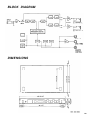
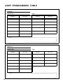
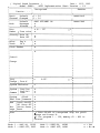
YAMAHA Digit a l M ulti-E ff e c t Pro c e s s or O p era ting M a nu al INTRODUCTION Congratulations on your purchase of a Yamaha SPX90 Digital Multi-Effect Processor. The SPX90 is an amalgam of advanced acoustical research and digital technology designed to provide musicians and home recording enthusiasts with a wide range of exciting effects. The SPX90 Digital Multi-Effect Processor utilizes highly refined LSI (Large Scale Integration) technology to create natural reverberation. Not only is its assortment of 30 preset effects comprehensive enough to suit most studio and performance applications, the SPX90 also allows you to create up to 60 additional effects and store them for instant recall. Your SPX90 can create effects far beyond mere reverberation, though that in itself is of a truly superior quality. A variety of echo, delay, and special effects—each with comprehensive parameter adjustments—can be accessed at the touch of a switch. And as the SPX90 is MIDI-compatible, it can be programmed to apply separate reverberation effects to a variety of MIDI-compatible instruments. Your SPX90 Digital Multi-Effect Processor will prove extremely useful in a variety of applications: acoustic electric, PA, MIDI instrument, and home recording systems. In order to take advantage of the vast potential of this component, we urge you to study this manual before connecting the SPX90 to your system. We at Yamaha thank you, and wish you years of enjoyment with your SPX90. CONTENTS PRECAUTIONS FRONT PANEL REAR PANEL BASIC OPERATIONS PRESET PROGRAM SELECTION EDIT: CHANGING PARAMETERS STORE: SAVING EDITED PROGRAMS OUTPUT BALANCE AND LEVEL PROGRAMMING BYPASS UTILITY FUNCTIONS EDIT TITLE MIDI FUNCTIONS FOOTSWITCH MEMORY RECALL RANGE DESCRIPTION OF PROGRAMS AND PARAMETERS REVERB ER1, ER2 DELAY ECHO MODULATION STEREO FLANGE CHORUS STEREO PHASING 1 2 3 4 5 5 5 6 7 7 8 8 8 9 10 10 10 11 11 12 12 13 TREMOLO SYMPHONIC PITCH CHANGE FREEZE REVERB & GATE GATE ADR-NOISE GATE COMPRESSOR PAN AUTO PAN TRIGGERED PAN DELAY VIBRATO PARAMETRIC EQ SAMPLE APPLICATIONS SPECIFICATIONS ROM CONTENTS AND CONTROLABLE PARAMETERS EARLY REFLECTION MODE CHART ROOM SIZE CHART BLOCK DIAGRAM DIMENSIONS USER PROGRAMMING TABLE MIDI IMPLEMENTATION CHART 13 13 13 14 17 17 18 19 19 20 20 21 23 24 26 27 28 28 29 30 PRECAUTIONS NOTE: It is vital to read this section before using your SPX90 Digital Multi-Effect Processor. This unit utilizes state-of-the-art digital technology which, although designed to provide years of trouble-free use, requires careful handling. VOLTAGE RATINGS Be sure the AC supply in your area is appropriate for your SPX90. U.S./Canadian Model: 110V — 120V, 50/60Hz. General Model: 220 — 240V, 50/60Hz. ENVIRONMENTAL TEMPERATURE Do not expose the SPX90 to excessive heat. The operating temperature range of this unit is between 0 and 40 degrees centigrade (32 and 104 degrees Fahrenheit). EXTERNAL CLEANING Do not clean the exterior of the SPX90 with solvents such as benzine or paint thinner. Dust, dirt, or fingermarks should simply be removed with a soft, dry cloth. Internal cleaning of the unit should only be performed by a qualified technician. The LCD may not function properly under extreme temperature conditions. It will return to normal after cooling down to within the proper temperature range. BACKUP BATTERY To ensure that User Programs are not lost when the SPX90’s power is turned off, a built-in long-life battery acts as a backup. In normal use, this battery lasts 5 years, but it is advisable to change the battery before this time has elapsed. Contact your local Yamaha dealer for details. NOTE: When you change the battery, the User Programs may be lost. As a safeguard, take note of all parameters of your User Programs in the USER PROGRAMMING TABLE accompanying this manual. The SPX90 can then be reprogrammed once a new battery is installed. The preset programs are permanent, and will not be affected by a change of battery. ERROR MESSAGES When power is initially turned ON an automatic circuit test program is executed to ensure proper operation. If an error is encountered, one of the following error messages will be displayed: E0 : ROM checksum error. E1 : CPU RAM read/write error. E2 : External RAM read/write error. Make a note of the error message and inform the service personnel when the unit is to be serviced. FCC CERTIFICATION (USA) This equipment generates and uses radio frequency energy and if not installed and used properly, that is, in strict accordance with the manufacturer’s instructions, may cause interference to radio and television reception. It has been type tested and found to comply with the limits for a Class B computing device in accordance with the specifications in Subpart J of Part 15 of FCC Rules, which are designed to provide reasonable protection against such interference in a residential installation. However, there is no guarantee that interference will not occur in a particular installation. If this equipment does cause interference to radio or television reception, which can be determined by turning the equipment off and on, the user is encouraged to try to correct the interference by one or more of the following measures: Reorient the receiving antenna. Relocate the computer with respect to the receiver. Move the computer away from the receiver. Plug the computer into a different outlet so that computer and receiver are on different branch circuits. If necessary, the user should consult the dealer or an experienced radio/television technician for additional suggestions. The user may find the following booklet prepared by the Federal Communications Commission helpful: “How to identify and Resolve Radio-TV interference Problems”. This booklet is available from the U.S. Government Printing Office, Washington, DC 20402, Stock No. 004-000-00345-4. 2 FRONT PANEL Power ON/OFF Switch When the power is turned ON, the program which was selected immediately before the power was turned OFF will be re-selected. Due to the safety muting circuit, no sound will be produced by the SPX90 for a few seconds after the power is turned 3 Input Level Control (0 ~ 10) Regulates the level of the input signal. Set the INPUT LEVEL control while watching the INPUT LEVEL meter. The seven LED meter segments should not all be continuously on when an input signal is applied, as this will result in input amplifier overload and distortion. When the INPUT LEVEL control is set to “8” on the scale, the input/output gain is 1 (unity). A setting of “10” increases gain by about 10 dB. Input Level Meter This easy-to-read LED level meter is a visual aid to setting appropriate input levels. Generally, the best input level setting will produce continuous lighting of the lower green LED segments, while the upper red segments flash only occasionally. Memory Number LED This LED display shows the number of the currently selected program. Memory numbers 1 through 30 contain factory-preset effects (ROM). Memory numbers 31 through 90 can be used to store edited versions of the preset effects (RAM). LCD Program and Parameter Indicator This high-contrast Liquid Crystal Display indicates the effect name and parameter data value. Parameter Key Selects successive effect parameters. Pressing this key sequentially calls the programmable parameters within the currently selected effect program. Once the desired parameter has been selected, the PARAMETER INCREMENT/DECREMENT keys are used to change the value of that parameter, thereby modifying the effect. The parameters available for each program are different: refer to the parameter chart on page 24. Parameter Increment/Decrement Keys These keys are used to change the value of a selected parameter. Press the increment key (up arrow) to increase the value, or the decrement key (down arrow) to decrease the value. Balance/Output Level Key Adjusts proportion of effect signal to direct signal. Pressing this key alternately causes the current balance and output level values to be displayed on the LCD. The Parameter Increment/Decrement keys are then used to adjust the displayed values. Store Key Stores any edited preset effect in a selected RAM memory position (31 ~ 90). Memory Increment/Decrement Keys These keys select any desired memory number to call a specific program or store an edited program in the user memory area. The selected memory number is shown on the MEMORY NUMBER display. When a new memory number is called, the MEMORY number display will flash until either the STORE or RECALL function is activated. Recall Key Press this key to recall the program that resides in the selected memory number. Utility Key Multi-purpose key accesses MIDI control functions, facilitates program title editing and sets footswitch memory control range. See pages 8 and 9 for details. Foot Trigger Key When this key is pressed and its LED is ON, the footswitch connected to the Memory/Trigger jack functions as a foot trigger for the GATE and FREEZE programs, rather than for memory selection. Bypass Key When this key is pressed, the effect signal is shut off and only the direct signal will be output. Direct signal level is affected by the INPUT LEVEL control setting. Memory/Trigger Footswitch Jack Facilitates remote memory selection via optional footswitch. The range of memory locations to be recalled by the footswitch can be set with a Utility program. When the foot trigger function (above) is ON, the footswitch connected to this jack acts as a trigger footswitch rather than memory control. Use of a Yamaha FC5 Foot Controller is recommended. Bypass Footswitch Jack Facilitates foot control of the BYPASS function described above. A Yamaha FC-5 Foot Controller is recommended. REAR PANEL Remote Control Connector Permits remote access to SPX90 effect programs. The optional remote control unit, model RC7, permits direct access to programs 1 through 7 and 31 through 37, while all other preset programs may be accessed sequentially. MIDI IN Connector Permits SPX90 effect programs to be automatically selected via a MIDI signal. This connector must be connected to the MIDI OUT connector of the transmitting MIDI instrument via a standard MIDI cable. Output Level Selector (– 20 dB, + 4 dB) Facilitates SPX90 source/line level (sensitivity) matching. This LED lights whenever a remote control key is pressed. Preset keys. It is possible to call user programs when this LED is lighted. MIDI THRU Connector Re-transmits MIDI data received at the MIDI IN connector to subsequent MIDI instruments. When this key is pressed, the USER LED will light and it becomes possible to select user programs 31 through 37. USER LED OFF USER LED ON — Preset programs — — User programs — 1. REV 1 HALL 3 1 . User program 2. REV 2 ROOM 3 2 . User program 3. REV 2 VOCAL 3 3 . User program 4. REV 4 PLATE 34. User program 5. EARLY REFLECTION 1 35. User program 6. EARLY REFLECTION 2 36. User program 7. DELAY L, R 37. User program Output Jacks (L and R) These are standard mono 1/4” phone jacks which deliver the direct and effect signal to subsequent mixing or amplification equipment. Since the SPX90 offers stereo output, we recommend that the output signal be fed in stereo to a stereo sound system in order to take full advantage of the superb stereo effects provided. Output impedance is 600 ohms. Input Level Selector ( – 20 dB, + 4 dB) Permits SPX90 source/line level (sensitivity) matching. Input jack This standard unbalanced mono 1/4” phone jack accepts the input signal to the SPX90. Input impedance is 10 k-ohms. 30. PARAMETRIC EQ (Programs 8 through 30 selected sequentially by pressing OTHERS/ -37key) 4 BASIC OPERATIONS Before actually selecting or editing programs on your SPX90, make sure that all connections have been made properly, and that the INPUT LEVEL switch, OUTPUT LEVEL switch, and INPUT LEVEL control have been properly set according to the source signal and equipment to which the SPX90 signal will be fed. PRESET PROGRAM SELECTION EDITING: CHANGING PARAMETERS Your SPX90 is equipped with a selection of 30 outstanding preset effect programs which are listed in the ROM CONTENTS AND CONTROLABLE PARAMETERS on page 24. The preset (and user) programs are selected as follows: 1. Use MEMORY INCREMENT/DECREMENT keys to select desired memory number (remember, 1 through 30 are the presets). The SPX90 offers incredible sonic flexibility, as each effect type comprises its own set of parameters (see parameter chart on page 24). These parameters can be adjusted to suit your tastes and the tonal characteristics of your musical equipment. We therefore recommend that you examine each preset effect program, and observe how these parameters affect the sound. You will soon discover many new and exciting applications for the SPX90’s preset effect programs. 2. Press RECALL key to call program in selected memory number. 1. Select and recall desired program as described above. 2. Press PARAMETER key to access the various parameters available in the selected program. Each time the PARAMETER key is pressed, the next parameter in the list is called. NOTE: The same process is used to select user pro grams (memory number 31 through 90) once you have edited and stored your own programs in user memory. 5 3. Use PARAMETER INCREMENT/DECREMENT keys to set desired value of the selected parameter. STORE: SAVING EDITED PROGRAMS Once you’ve edited parameters on a preset program, those changes will remain in effect only until you select (RECALL) another program. The STORE function, however, allows you to save the edited program in any one of the user memory locations — from 31 to 90 — from which it can then be recalled at any time. 1. Select and edit a program as described above. 2. Use the MEMORY INCREMENT/DECREMENT keys to select a clear memory location between 31 and 90. 3. Press the STORE key. NOTE: A description of each parameter and its effect will be given in the PROGRAMMABLE PARAMETERS section, beginning on page 10. The edited program has now been stored in the selected user memory location. The stored program may now be recalled at any time by following the normal program selection procedure. NOTE: If you attempt to store a program in one of the read-only preset locations (1 through 30), the SPX90 will display the “# 1 ~ # 30 READ ONLY” error message. : SPX90 has an Edit Title Function, so you can which allows you to provide your own titles for edited programs. (See the UTILITY function on page 8.) 6 OUTPUT BALANCE AND LEVEL PROGRAMMING The BALANCE key selects the BALANCE and OUTPUT LEVEL functions for all programs. 1. Press the BALANCE key while any parameter is selected. 2. The first function called will be BALANCE. Adjust the BALANCE of the effected and direct signal between 0 and 100% using the PARAMETER INCREMENT/DECREMENT keys. * Balance = 100% : effect sound only. Balance = 0% : direct sound only. 3. Press the BALANCE key again to call the OUTPUT LEVEL function. Adjust using the PARAMETER INCREMENT/DECREMENT keys. * OUT LVL = 100% : maximum output level. OUT LVL = 0% : no sound will be output. 7 BYPASS When the BYPASS key is pressed and its LED lights, the effect signal is defeated and only the direct input signal is delivered via the OUTPUT jacks. The BALANCE and OUTPUT LEVEL functions are also bypassed. The BYPASS function can also be activated via a footswitch connected to the BYPASS jack. A normallyclosed-type footswitch such as the Yamaha FC-5 must be used. UTILITY FUNCTIONS The UTILITY key provides access to four utility functions. These functions are selected in the following sequence each time the UTILITY key is pressed: MIDI CONTROL Normal mode EDIT TITLE MIDI PROGRAM CHANGE FOOTSWITCH MEMORY RECALL Normal mode. The UTILITY key LED will light during selection of the four utility functions, and will go out when the normal mode is returned to. When the UTILITY LED is ON, the PARAMETER and MEMORY NUMBER INCREMENT/ DECREMENT keys will perform special functions as described below, so normal parameter and memory selection can not be performed until the normal mode is selected. EDIT TITLE This function makes it possible to provide new titles for programs which you have edited and stored in user memory (31 through 90). When the EDIT TITLE function is called, the lower line of the LCD will display the “EDIT TITLE” function name, and the upper line will display the title of the currently selected program. The PARAMETER and BALANCE keys can then be used to move the cursor left and right, respectively, to select the character to be changed. Place the cursor over a character, then use the PARAMETER INCREMENT/DECREMENT keys to scroll through the character list, stopping at the desired character. Move the cursor to the next character location and repeat this operation until the new title is complete. The available characters are as follows: MIDI FUNCTIONS With the SPX90 it is possible to select specific programs via external MIDI control. For example, you can set the SPX90 so that when you select a specific voice on your MIDI synthesizer, the most appropriate effect program for that voice is selected automatically. In this case, the SPX90 is detecting the MIDI Program Change signal. For the following programs only, the SPX90 also detects the MIDI Note ON/OFF signal: * GATE programs (GATE ON/OFF). * PITCH programs (sets pitch). * FREEZE programs (begin playback). For MIDI program change operation, it is possible to program four independent sets of program change/memory number combinations. These are referred to as “banks” in the SPX90. For example, you could program the four banks with different combinations as shown in the chart below. The second function accessed by the UTILITY key — MIDI CNTRL — permits BANK selection and setting of the MIDI channel number on which MIDI program change data for that BANK will be received. The third function accessed by the UTILITY key — MIDI PGM CHANGE — makes it possible to set the SPX memory number which will be called when a specific MIDI program change number is received. 8 MIDI Bank and Channel Programming When this function is called, the LCD will appear as follows: Use the PARAMETER INCREMENT/DECREMENT keys to select the desired BANK, and the MEMORY INCREMENT/DECREMENT keys to select the desired MIDI channel number for that BANK. When “CH = OMNI” is selected, reception will be carried out on all 16 MIDI channels simultaneously. When CH = OFF is selected, MIDI reception will be turned OFF. Use the PARAMETER INCREMENT/DECREMENT keys to set the MIDI program number (PGM), and the MEMORY INCREMENT/DECREMENT keys to select the SPX90 memory number (MEM) to be called when that program number is received. For example, if “PGM 12 = MEM 4” is set, SPX90 memory number 4 will automatically be called whenever voice number 12 is selected on your MIDI synthesizer. The MIDI program number range is from 1 to 128, while the SPX90 memory number range is from 1 to 90. FOOTSWITCH MEMORY RECALL RANGE The SPX90 permits memory number selection via a footswitch plugged into the front-panel MEMORY/ TRIGGER jack. The fourth function accessed by the UTILITY key — FOOTSWITCH MEMORY RECALL — permits setting the range of memory numbers to be selected via the footswitch. If, for example, the RANGE is set to “1 TO 30” as shown on the LCD above, each press on the footswitch will successively call the next highest memory number: 1 2 3 . . . . . . . . 30 1. Note that the sequence returns to the first number in the range once the highest number is passed. Reverse sequences can be programmed by entering the highest number in the range before the lowest. Setting MIDI Program Number/SPX90 Memory Number Combinations. When this function is called by pressing the utility key again the LCD will appear as follows: In this case the sequence is: 34 34, etc. 9 33 32 31 DESCRIPTION OF PROGRAMS AND PARAMETERS The preset programs in the SPX90 fall into the following types: REV (Reverb), ER1 and ER2 (Early Reflections), DELAY, ECHO, MOD (Modulation), GATE, PITCH, FREEZE, PAN, VIBRATO and PEQ (parametric equalizer). Each of these program types has a specific selection of programmable parameters. “Parameters” indicates the separate, individual functions that make up each effect. There are two types of parameters in the SPX90: “invisible” parameters (non-programmable, fixed-value parameters) and programmable parameters (those you can edit, or modify). Most commonly associated with-musical “ambience,” reverberation is a result of myriad reflected sound waves within an acoustical environment, i.e. a concert hall, auditorium, or soundstage. The SPX90 creates extremely vibrant, natural sounding reverb. 1. REVERBERATION TIME (R/T). Range: 0.3 ~ 99.0 sec The length of the time it takes for the level of reverberation at 1 kHz to decrease by 60 dBvirtually to silence. In a live setting, this depends on several factors: room size, room shape, type of reflective surfaces, among others. 2. HIGH (High Frequency Reverb Time Ratio). Range: 0.1 ~ 1.0 Natural reverberation varies according to the frequency of the sound — the higher the frequency, the more the sound tends to be absorbed by walls, furnishings, and even air. This parameter permits you to alter the reverberation time of the high frequencies in proportion to the mid-frequency reverb time. 3. DELAY. Range: 0.1 ~ 50.0 msec For a listener in a concert hall; there is a time delay between the direct sound of the instrument, and the first of the many reflected sounds that together are known as reverberation. On the SPX90, this is known as the DELAY time. 4. HPF (High Pass Filter). Range: THRU, 32 Hz ~ 1 kHz Permits cutting the low frequency content of the reverb signal below the set frequency. When set to THRU, the HPF is OFF. 5. LPF (Low Pass Filter). Range: 1 kHz ~ 11 kHz, THRU Permits cutting the high frequency content of the reverb signal above the set frequency. When set to THRU, the LFP is OFF. “Early Reflection” effects. ER1 has fewer reflections, and is a LOW DENSITY early reflection effect, while ER2 has more reflections, and is a HIGH DENSITY early reflection effect. 1. TYPE. Range: HALL, RANDOM, PLATE, REVERSE TYPE selects the pattern of the earliest reflections of the reverb sound. All “Early Reflection” presets are switchable between 4 different types. These are HALL (a typical grouping of early reflections that would occur in a performing environment like a hall), RANDOM (an irregular series of reflections that could not occur naturally), PLATE (a typical grouping of early reflections that would occur in a plate reverb unit), and REVERSE (a series of reflections that increase in level, like the effect produced by playing a recorded reverb/echo backwards). See the E/R Mode chart on page 26. 2. ROOM SIZE. RANGE: 1.0 ~ 20.0 The ROOM SIZE parameter sets the time “gaps” between the early reflections — directly proportionate to the size of the room. The effect of this parameter also depends on which Early Reflection mode has been selected. A Room Size Chart can be found on page 27 in this manual. 3. LIVENESS. Range: 0 ~ 10 Refers to the rate at which the reflected sounds fade. Set this parameter at zero to simulate an acoustically “dead” room, with absorbent surfaces to “soak up” the reflected sounds. As you increase the setting, the room appears to contain more “live” surfaces, with the reflected sounds fading more slowly, as they reflect from wall to wall, until at the maximum setting the effect is of an intensely reflective environment containing many highly polished surfaces (tiles, glass, etc). 4. DELAY. Range: 0.1 ~ 400 msec The time delay between the direct sound of the instrument and the first reflection to reach the listener’s ear. 5. LPF Range: 1 kHz ~ 11 kHz, THRU Same function as the LPF parameter of the pro10 grams. This effect, commonly used in contemporary recordings, produces independently variable left- and rightchannel signal delays. The result is an intriguing “doubled” sound. 1. LEFT CHANNEL DELAY TIME. Range: 0.1 ~ 500.0 msec Permits highly accurate setting of the left channel delay following the direct sound. 2. LEFT CHANNEL FEEDBACK GAIN. Range: – 99% ~ + 99% Sets the amount of delay signal fed back to the input circuitry. The higher the feedback gain setting the greater the number of delay repeats produced. A negative value setting produces out of phase feedback. 3. RIGHT CHANNEL DELAY TIME. Range: 0.1 ~ 500.0 msec Sets the delay time of the right channel. 4. RIGHT CHANNEL FEEDBACK GAIN. Range: – 99% ~+99% Permits setting the feedback gain setting of the right channel delay. 5. HIGH (FEEDBACK HIGH). Range: 0.1 ~ 1.0 Controls feedback of the high-frequency range. The high frequency feedback is reduced as the value of this parameter is reduced. Similar to Delay, Echo brings added dimension and force to both instrumental and vocal music. While Reverberation recreates an abundance of partial sound reflections, and Delay produces a limited number of signal repetitions, Echo can produce limitless signal repetitions. 1. LEFT CHANNEL DELAY TIME. Range: 0.1 ~ 250.0 msec After this delay time has elapsed, the first echo will appear. Subsequent echoes will appear at the same time interval, the number of echoes depending on how the Feedback Gain parameter is set. 2. LEFT CHANNEL FEEDBACK GAIN. Range: – 99% ~ + 99% This parameter permits adjustment of the number of echoes that follow the direct signal, from zero to a virtually infinite repeat at the maximum setting. The overall decay time of the effect is proportionate to the Feedback Gain setting. 3. RIGHT CHANNEL DELAY TIME. Range: 0.1 ~ 250.0 msec 4. RIGHT CHANNEL FEEDBACK GAIN. Range: – 99% ~ + 99% Parameter 3 and 4 have the same function as those of 1 and 2 but the signal will be produced from the Right output. 5. HIGH (FEEDBACK HIGH). Range: 0.1 ~ 1.0 Determines the portion of high frequency feedback. The lower the value, the less high frequency is produced. 11 STEREO FLANGE CHORUS A combination of Delay and LFO (Low Frequency Oscillation) modulation, the popular Flanging effect can dramatically thicken the sound of keyboard instruments, or produce the “aircraft” sound popular among guitarists. Basically, a short delay time is varied with LFO modulation so that the delayed signal moves in relation to the direct signal. The resultant variations in pitch and stereo imaging are known as “flanging”. With the Chorus effect, a violin, keyboard, or guitar can sound like an entire ensemble. Chorusing splits the incoming signal into three signals placed at the center, left, and right in the stereo image. Each signal is delayed slightly, and then its delay time and level are modulated by the LFO (Low Frequency Oscillator). 1. MOD FREQ. Range: 0.1 ~ 20.0 Hz Sets the speed of modulation, and hence the rate at which the effect varies. 1. MOD FREQ. Range: 0.1 ~ 20.0 Hz Sets the delay time modulation speed (frequency). 2. MOD DEPTH. Range: 0 ~ 100% This sets the amount of delay time variation, thus adjusting the “depth” of the effect. At the maximum setting, the delay time is varied by +/4 msec. 3. MOD DELAY TIME. Range: 0.1 ~ 100 msec This sets the basic delay time from the initial direct sound to the flange effect. When set to lower than 1 msec, more high-frequency variation is produced, while a setting higher than 3 msec will create more low-frequency variation. 2. DELAY MODULATION DEPTH. Range: 0 ~ 100% This sets the amount by which the delay time of one delay signal is varied in relation to the other. At the maximum setting, the delay time is varied by +/4 msec. 3. AMPLITUDE MODULATION DEPTH. Range: 0 ~ 100% This sets the amount by which the amplitude (level) of the input signal is varied. 4. F. B. GAIN. Range: 0 ~ 99% Sets the amount of flange signal which is fed back into the circuit for further modulation. This controls the complexity of the effect, its “strength,” and its overall decay time. 12 STEREO PHASING The SPX90 can produce a wide range of Phasing effects from a barely perceptible shift to a rapid pulsation. Phasing lends an animated quality to musical instrument and vocal recordings: This effect has the same parameters as STEREO FLANGE, except that the DELAY TIME range is from 0.1 to 8.0 msec and omits FB Gain. TREMOLO The TREMOLO effect operates in the same way as the CHORUS effect, except that modulation is deeper and the delay variation is greater. Refer to STEREO FLANGE for the description of the parameters. SYMPHONIC The programmable parameters for this preset are identical to those for the Stereo Flange preset, omitting FEEDBACK GAIN and MOD DELAY. This program is used to change the pitch of an input signal. Pitch can be changed in semitone increments over a plus/minus one-octave range. Fine adjustment of pitch in one-cent (1/100th of a semitone) increments/decrements is also possible. Pitch change programs B and C permit setting two different pitches. This makes it possible to produce harmonizer type effects (i.e. when you play a note the SPX90 outputs two additional notes), or, if only a slight pitch difference is used, chorus-type effects are created. Pitch change programs A and D permit the application of feedback so that an echo that changes in pitch with each repeat can be produced. Programs A and D further permit pitch control via the MIDI IN connector. Any MIDI synthesizer, such as the Yamaha DX7, can be used to alter the pitch setting of the program by simply playing the appropriate note on the synthesizer keyboard. PITCH CHANGE FEEDBACK MIDI PITCH CONTROL PITCH CHANGE A 1 TONE YES YES PITCH CHANGE B 2 TONES (CENTER) NO NO PITCH CHANGE C 2 TONES (1 EACH IN L & R CH.) NO NO PITCH CHANGE D 1 TONE YES YES PROGRAM 1. PITCH. Range: – 12 ~ + 12 Sets the degree of pitch change in semitone steps. + 12 corresponds to an output pitch one octave higher than the input pitch, and – 12 produces an output pitch one octave lower than the input pitch. 2. FINE. Range: – 100 ~ + 100 Adjusts pitch in one-cent increments or decrements. 3. DELAY Range: 0.1 ~ 400 msec (A, B, D), 0.1 ~ 200 msec (C) Sets the delay between the direct (input signal) and the pitch-changed output signal. 4. F. B. GAIN. Range: 0 ~ 99% (A, D only) The higher this setting, the more echo repeats are produced (each changed in pitch from the previous repeat). 5. BASE KEY. Range: OFF, C1 ~ C6 (A, D only) This parameter sets the “BASE KEY” for an external MIDI synthesizer used to control the pitch varia- 13 tion of the PITCH CHANGE program. For example, if BASE KEY = C4, then pressing the C3 key on the synthesizer keyboard will set the pitch change value to – 12 (one octave down). Pressing D4 on the keyboard would produce a pitch increase of one tone (+ 2). If a key more than one octave higher or lower than the BASE KEY is pressed, the resultant pitch change setting will still be within the + 12 to – 12 range, as shown in the following illustration. If the BASE KEY setting is OFF, pitch can not be controlled via the MIDI IN terminal. The FREEZE programs permit “recording” up to a 500-millisecond signal in the SPX90 memory; and playing it back as required. The FREEZE programs have two basic steps: RECORD and PLAY. With the FREEZE A program it is possible to program a specific segment of the recorded 500-millisecond signal to be replayed by programming the START and END points. The FREEZE B program does not permit programming START and END points, but the pitch of the recorded signal can be changed for playback. 1. REC. MODE Selection. Range: Manual, Auto Press the Parameter key and select the Manual mode with the Parameter Increment key or AUTO Mode by pressing the Parameter Decrement key. In the MANUAL mode a Parameter Increment panel key is pressed to begin recording, while in the AUTO mode recording begins automatically when the SPX90 detects an input signal. 2. TRIGGER DELAY Parameter. Range: – 500 ~ 500 msec. This parameter determines the actual point at which recording begins in relation to the trigger signal. If TRG DLY is set at 0, recording begins immediately when the FREEZE function is triggered. If a negative TRG DLY value is set the input signal is delayed so that in effect recording begins before the function is triggered. 3 . RECORDING After the desired MODE has been set, press the PARAMETER key and the LCD will display the “RECORD” message. Then, enter the standby mode by pressing the PARAMETER DECREMENT key. The LCD will display the “REC READY” message. 14 TRIGGERING MANUAL Mode To actually begin recording if the MANUAL mode has been selected, press the PARAMETER INCREMENT key. The SPX90 will record for 500 milliseconds. Also the optional foot switch FC-5 can be used. Connect the FC-5 to the MEMORY/TRIGGER Foot Switch Jack and press the FOOT TRIGGER Key. Then FC-5 works as the trigger switch when it is pressed. AUTO Mode If the AUTO mode has been selected, the SPX90 will automatically begin recording when an input signal of sufficient level is detected. The LCD displays “TRIGGER!” when the freeze function is triggered. When the recording begins the LCD displays “......”. The freeze (recording) ends automatically after 500msec and the display says “OK”. 4. OVERDUB Recording To “overdub,” or record new material without erasing the previously recorded material, use the following procedure. 1. Press the PARAMETER key until the OVERDUB display appears. 2. Press the PARAMETER DECREMENT key. This sets the record ready status, and recording will begin as soon as a trigger signal is received. FREEZE operation * To begin recording again, press the parameter decrement key to enter the Rec Ready Mode. 15 5. PLAYBACK To play back the recorded material, press the PARAMETER key to enter the playback standby mode. The LCD will display the “PLAY” message. To actually play the recording, press the PARAMETER INCREMENT/DECREMENT key. The recorded material will be played each time the PARAMETER INCREMENT/DECREMENT key is pressed. To program a specific segment of the recording to be played back in the FREEZE A program, set the START and END parameters to appropriate values (0 ~ 500). The example below depicts how the START and END parameters affect output. START/END POINTS Another way to trigger playback is to use the Input Trigger Parameter. Select the Input Trigger Parameter and press the parameter Increment key to enter the standby mode. Playback will be automatically triggered when the input signal exceeds nominal level. The FREEZE B program PITCH and FINE parameters function identically to those in the PITCH CHANGE program to change the pitch of the playback signal. Playback start and stop can be triggered by the PARAMETER INCREMENT/DECREMENT keys, foot switch or via a MIDI keyboard connected to the MIDI IN connector. With the FREEZE B program, playing a key on the MIDI keyboard produces the corresponding pitch change in the playback output, and triggers playback. PLAYBACK SIGNAL “GOOD LUCK” “OOD LUCK” “LUCK” “OD LU” “LUCK GOOD” Playback can also be triggered by a footswitch connected to the front-panel MEMORY/FOOT TRIGGER jack when the FOOT TRIGGER key is pressed and its LED is ON. A MIDI keyboard connected to the MIDI IN terminal can also be used to trigger playback — simply play a note on the keyboard. 16 This program feeds the reverb signal through a gate circuit, making it possible to output only a segment of a longer reverb sound. Parameters provided for the reverb portion of the signal are REV TIME, HIGH, DELAY, HPF and LPF, while parameters for the gate portion are HOLD TIME, RELEASE TIME, and MIDI TRIGGER. ADR-NOISE GATE This program uses a gate circuit to pass or shut off the input signal in a number of ways. It can be used to pass just a short segment of a longer input signal, or it can be used to pass only signals that exceed a specific level (noise-gate type operation). It is also possible to achieve reverse gate effects in which the gain increases gradually after the gate is triggered. In addition to signal-level triggering, it is also possible to trigger the gate via a footswitch connected to the front-panel MEMORY TRIGGER jack when the FOOT TRIGGER key LED is ON. 1 . REVERB TIME (R/T). Range: 0.3 ~ 99.0 sec 2. HIGH (High Frequency Reverb Time Ratio Range: 0.1 ~ 1.0 3. DELAY. Range: 0.1 ~ 50.0 msec 4 . HPF (High Pass Filter). Range: 32 Hz ~ 1.0 kHz, THRU 5. LPF (Low Pass Filter). Range: 1.0 kHz ~ 11 kHz All these parameters have the same function as those of the REV programs. See page 10 for details. 6. TRIGGER LEVEL. Range: 0 ~ 100% Determines the strength (amplitude) of the input signal required to trigger opening of the gate. At 100%, only extremely high-level input signals will trigger the gate, while at 0% even this slightest input signal will trigger the gate. 7. HOLD TIME. Range: 1 ~ 30,000 msec This parameter sets the amount of time the gate is “open,” allowing the reverb sound to come through. 8. RELEASE TIME. Range: 5 ~ 32,000 msec This parameter determines the time it takes for the gate to close completely after the HOLD TIME. 9. MIDI TRIGGER. Range: ON, OFF When ON, a KEY ON signal from an external MIDI keyboard can be used to trigger the R & G effect. 17 1. TRIGGER LEVEL. Range: 1 ~ 100% Determines the strength (amplitude) of the input signal required to trigger opening of the gate. At 100%, only extremely high level input signals will trigger the gate, while at 0% even the slightest input signal will trigger the gate. 2. TRIGGER DELAY. Range: – 100 ~ 100 msec Produces a delay between the time at which the gate is triggered and that at which it actually opens. If a minus value is programmed, the input signal itself is delayed so that, effectively, the gate opens before the signal appears. 3. TRIGGER MASK. Range: 5 ~ 32,000 msec This parameter makes it impossible to re-trigger the gate function until the programmed time has elapsed. 4. ATTACK TIME. Range: 5 msec ~ 32,000 msec Determines how long it takes for the gate to open fully from the time it begins to open. 5. DECAY TIME. Range: 5 msec ~ 32,000 msec Determines the length of time it takes for the gate to fall to DECAY LEVEL after it is fully open. 6. DECAY LEVEL. Range: 0 ~ 100% Determines the level at which the gate remains open for the HOLD TIME. The lower the value the lower the HOLD gate level. 7. HOLD TIME. Range: 1 msec ~ 30,000 msec Determines how long the gate stays open, allowing the input signal to pass. COMPRESSOR The COMPRESSOR effect reduces the level of the attack portion of a music signal and keeps overall signal level within narrow limits. 8. RELEASE TIME. Range: 5 msec ~ 32,000 msec Determines how long it takes for the gate to close fully from the time it begins to close. 9. MIDI TRIGGER. Range: ON, OFF When ON, a KEY ON signal from an external MIDI keyboard can be used to trigger the gate. 1. TRIGGER LEVEL. Range: 1 ~ 100% Determines the strength of the attack signal required to trigger the compressor effect. 2. TRIGGER DELAY. Range: – 100 ~ 100 msec Produces a delay between the time at which the effect is triggered and that at which the compression actually begins. If a negative value is programmed, the input signal is delayed so that effectively, the compression begins before the signal appears. 3. TRIGGER MASK. Range: 5 ~ 32,000 msec This parameter makes it impossible to re-trigger the compressor function until the programmed time has elapsed. 4. ATTACK TIME. Range: 5 msec ~ 32,000 msec Determines how long it takes until the HOLD level (below) is reached after the effect is triggered. 5. HOLD TIME. Range: 1 msec ~ 30,000 msec Determines how long the maximum compression effect is maintained after the ATTACK TIME has elapsed. 6. HOLD LEVEL. Range: 0 ~ 100% Determines the actual level to which all input signals will be compressed during the HOLD TIME. The smaller the value, the lower the level of the output signal. 7. RELEASE TIME. Range: 5 msec ~ 32,000 msec Determines how long it takes to return to normal level once the HOLD TIME has elapsed. 8. MIDI TRIGGER. Range: ON, OFF When ON, a KEY ON signal from an external MIDI keyboard can be used to trigger the compressor effect. 18 AUTO PAN TRIGGERED PAN This program automatically pans the sound image between left and right in the stereo sound field. Pan direction, speed, and phase can be programmed. In this program the pan effect is triggered by the input signal or footswitch. 1. PAN SPEED. Range: 0.1 ~ 20.0 Hz Sets the speed of pan. 2. DIRECTION. Range: L R, L R, L Determines the direction of pan. R 3. DEPTH. Range: 0 ~ 100% Sets the degree of level variation. The higher the value, the stronger the pan effect. 1. TRIGGER LEVEL. Range: 1 ~ 100% Determines the strength of the attack signal required to trigger the pan effect. The higher the value, the higher the input signal level required to trigger the effect. 2. TRIGGER DELAY. Range: – 100 ~ 100 msec Produces a delay between the time at which the effect is triggered and that at which the pan effect actually begins. If a negative value is programmed, the input signal is delayed so that effectively, the pan effect begins before the signal appears. 3. TRIGGER MASK. Range: 5 ~ 32,000 msec This parameter makes it impossible to re-trigger the pan function until the programmed time has elapsed. 4. ATTACK TIME. Range: 5 mec ~ 32 sec Determines how quickly or slowly the pan effect reaches maximum depth after it is triggered. 5. PANNING TIME. Range: 5 msec ~ 32 sec Determines how long the maximum-depth pan effect remains active. 6. RELEASE TIME. Range: 5 msec ~ 32 sec Determines how long it takes for the pan effect to fade out after the PANNING TIME has elapsed. 7. DIRECTION. Range: L R, L Sets the direction of pan. R 8. L/R BALANCE. Range: 0 ~ 100% Determines the volume balance between the left and right channels. 9. MIDI TRIGGER. Range: ON, OFF When ON, a KEY ON signal from an external MIDI keyboard can be used to trigger the pan effect. NOTE: To use footswitch FC-5, connect the FC-5 to the MEMORY/TRIGGER FOOT Switch Jack and press the Foot Trigger key. 19 This program makes it possible to add delay vibrato effects to virtually any instrument or sound. When the input signal exceeds a programmed trigger level, the vibrato effect is cancelled and then gradually builds up to the programmed depth. This program permits variation of the input signal frequency response over an extremely broad range. 1. TRIGGER LEVEL. Range: 1 ~ 100% Determines the input signal level at which the vibrato effect is cancelled and begins to build up again. 2. VIBRATO DELAY. Range: 1 ~ 30,000 msec Determines how long the vibrato effect is cancelled once triggered. 3. VIBRATO RISE TIME. Range: 5 msec ~ 32,000 msec Determines how long it takes for the vibrato effect to reach maximum depth after the VIBRATO DELAY time has elapsed. 4. VIBRATO FREQUENCY. Range: 0.1 ~ 20.0 Hz This parameter sets the frequency (speed) of the vibrato effect. 5. VIBRATO DEPTH. Range: 0 ~ 100% Sets the depth (strength) of the vibrato effect. 6. MIDI TRIGGER. Range: ON, OFF When ON, a KEY ON signal from an external MIDI keyboard can be used to trigger the vibrato effect. 1. HPF. Range: THRU, 32 Hz ~ 1.0 kHz. This sets the cutoff frequency of the high-pass filter. Frequencies below the set frequency are rolled off at a rate of 6 dB/octave. When set to THRU, the HPF is OFF. 2. MID FRQ. Range: 315 Hz ~ 4.0 kHz Determines the center frequency of the midrange equalization band. The midrange frequency can be set in 1/6 octave increments. 3. MID GAIN. Range: – 15 ~ + 15 dB Determines the amount of boost or cut applied to the midrange equalization band. 4. MID Q. Range: 0.5 ~ 5.0 Sets the “Q” (Quality factor = bandwidth) of the midrange EQ band. The higher the value, the narrower the bandwidth. 5. HI FRQ. Range: 800 Hz ~ 8.0 kHz Determines the center frequency of the highfrequency equalization band. 6. HI GAIN. Range: – 15 ~ + 15 dB Determines the amount of boost or cut applied to the high-frequency equalization band. 7. HI Q. Range: 0.5 ~ 5.0 Sets the “Q” (Quality factor = bandwidth) of the high EQ band. The higher the value, the narrower the bandwidth. 8. LPF. Range: 1 kHz ~ 11 kHz, THRU Determines the cutoff frequency of the low-pass filter. 9. DELAY. Range: 0.1 ~ 400.0 msec Sets the delay time of equalized signal following the direct signal. 20 SAMPLE APPLICATIONS MIDI KEYBOARD PERFORMANCE SYSTEM In this system the SPX90 is connected immediately following a MIDI keyboard, and its output feeds either an instrument amplifier or sound reinforcement mixing console. The MIDI OUT terminal of the keyboard is connected to the MIDI IN terminal of the SPX90, permitting automatic selection of different effects programs for specific voices selected at the keyboard. The SPX90 is under direct control of the keyboard player (rather than the mixing engineer) so he can produce exactly the effects he wants for each voice or musical selection. In a multi-keyboard system the SPX90 could be patched into the effects loop of the keyboard mixer. The MIDI keyboards could be chained MIDI IN MIDI THRU MIDI IN MIDI THRU together via the MIDI THRU terminals (MIDI OUT etc.) with the SPX90 MIDI IN terminal fed from the MIDI THRU terminal of the last keyboard in the chain. This way, all keyboards in the system could be used for MIDI effect selection. (SYSTEM DIAGRAM 1) BASIC SOUND REINFORCEMENT SYSTEM The SPX90 is an excellent addition to the small to medium size sound reinforcement system. Its input can be fed from either a mono effects send or auxilliary send bus on the mixing console, and its stereo outputs can be fed back to the corresponding effects or auxilliary return inputs on the console. Assuming the console used has independent effects or auxilliary send level controls on each input channel, it is possible to add the required amount of SPX90 effect to each input. It is also possible to use two SPX90 units for full stereo reverb and effects in a larger system. (SYSTEM DIAGRAM 2) 21 RECORDING SYSTEM In a recording system it is most desirable to have the SPX90 input and outputs available at a patch bay where they may accessed and patched into virtually any part of the system. In some cases it might be best to have the SPX90 connected directly in line between the source and the mixing console inputs, while in other situations—final mixdown, for example—the SPX90 should be patched into the mixing console’s effects loop so it may be applied to the entire mix. Naturally, the SPX90 is also an ideal choice for the truly modern digital sequencer recording system, too. (SYSTEM DIAGRAM 3) 22 SPECIFICATIONS INPUT Number of Channels Nominal Level Impedance Level Control Level Monitor Unbalanced x 1 (Phone Jack) – 20 dBm/+4 dBm, Selectable 10 k-ohms Volume, Max. Gain + 12 dB 7 points LED A/D CONVERSION Sampling Freq. Quantization Band Width Number of Channels 31.25 kHz Linear 16 Bit 20 Hz to 12 kHz 1 D/A CONVERSION Number of Channels Sampling Freq. Quantization Band Width 2 31.25 kHz Linear 16 Bit 20 Hz to 12 kHz OUTPUT Number of Channels Nominal Level Impedance Mixing Bypass Unbalanced x 2 (Phone Jack) – 20 dBm/+4 dBm, Selectable 600 ohms Direct Signal, Effect Signal ON/OFF MEMORY Presets (ROM) User Memory (RAM) MIDI CONTROL FRONT PANEL Display Knob Keys 23 1~30 31 ~ 90 (Non Volatile) All parameters except Input Level, can be memorized Key On triggers the program 18, 19, 20, 28 and 29 MIDI Channel (1 to 16, OMNI), (4 banks), Program Number (1 to 128) Note on/off is recognized only for pitch change A, D and freeze B 16 character 2 lines LCD x 1, 2 digits numeric LED for Memory No., 7 points level meter LED Input Level Volume Parameter/Balance/Data Increment/Data Decrement, Memory Store/ Recall/Data Increment/Data Decrement, Utility/Foot Trigger/ Bypass ELECTRICAL CHARACTERISTICS Reverb: more than 75 dB Dynamic Range Delay : more than 81 dB Distortion Bypassed Signal: less than 0.01% Effect Signal : less than 0.03% Bypassed Signal: 20 Hz to 20 Band Width kHz Effect Signal : 20 Hz to 12 kHz POWER SUPPLY U. S. & Canadian Models General Model 110V – 120V, 60Hz 220V – 240V, 50/60Hz POWER CONSUMPTION U. S. & Canadian Models General Model 20W 20W DIMENSIONS (W x H x D) 480mm x 45.2mm x 285mm (18-7/8” x 1-3/4” x 11-1/4”) WEIGHT 3.2 kg (7 Ibs) OPTIONAL REMOTE CONTROL (model RC7) PRESET PROGRAM 1 ~ 30, USER MEMORY 31 ~ 37 * NOTE: Since natural sounding reverberation is mixed with the direct sound, and hence does not constitute 100% of the sound, the effective dynamic range will nearly always exceed 90 dB. ** 0 dBu is 0.775 volts RMS. This value represents voltage across a high impedance input. dBu is the equivalent of dBu if specified across a 600 ohm load. ROM CONTENTS AND CONTROLABLE PARAMETERS 24 25 ROOM SIZE CHART EARLY REFLECTION MODE CHART 26 27 EARLY REFLECTION MODE CHART 26 ROOM SIZE CHART 27 BLOCK DIAGRAM DIMENSIONS 28 USER PROGRAMMING TABLE Program No. Type Progaram Title Parameter New Value Parameter New Value Parameter New Value Remarks Program No. Type Progaram Title Parameter Remarks 29 New Value [ Digital Sound Processor ] Date : 10/5, 1985 Model SPX90 MIDI Implementation Chart Version : 1.0 Function . . . Basic Default Channel Changed Recognized 1-16 1-16 memorized memorized Mode Default Messages Altered OMNI OFF/OMNI ON x x Note Number True voice o Ø - 127 x Velocity Note ON Note OFF x x After Touch x x Key's Ch's Pitch Bender Remarks 1 x x Control Change Prog Change True # o System Exclusive o System x x x Common Song Pos Song Sel Tune System Real Time Aux Message Notes Clock Commands x x Local ON/OFF All Notes OFF Active Sense Reset x x x x 0-127 2 1 Note ON/OFF is recognized only for pitch change and freeze B. 2 For program 1 - 128, memory #1 - #90 is selected. Mode 1 : OMNI ON, POLY Mode 3 : OMNI OFF, POLY Mode 2 : OMNI ON, MONO Mode 4 : OMNI OFF, MONO o : Yes x : No 30 SINCE 1887 YAMAHA NIPPON GAKKI CO., LTD. HAMAMATSU, JAPAN SERVICE The SPX90 is supported by Yamaha’s worldwide network of factory trained and qualified dealer service personnel. In the event of a problem, contact your nearest Yamaha dealer. OMD-163 85124 printed in Japan