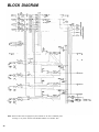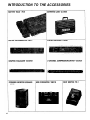
1
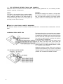
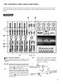
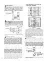
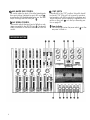
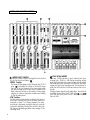
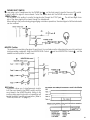
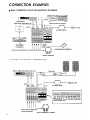
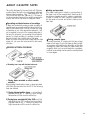
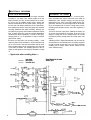
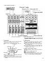
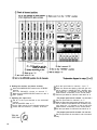
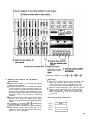
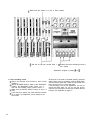
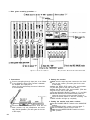
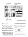
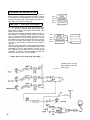
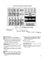
YAMAHA
®
AUTHORIZED
PRODUCT MANUAL
YAMAHA
MULTITRACK CASSETTE RECORDER
OPERATING MANUAL
Congratulations on your choice of the New Yamaha MT1X Multitrack
Cassette Recorder. The MT1X is a compact multitrack recorder with a
recording mixer, and is equipped with numerous versatile functions. Using
conventional cassette tapes, the MT1X makes it easy for you to produce
high quality multitrack recordings. Besides use as a multitrack recorder,
the MT1X can also be used as a PA mixer for small performances, as well
as for editing soundtracks for videos.
To take full advantage of the outstanding array of features, and for years
of trouble-free operation, we urge you to thoroughly read this operating
manual. After reading, keep it in a handy place for reference.
CONTENTS
BEFORE OPERATION . . . . . . . . . . . . . . . . . . . . . . . . . .............
PLEASE NOTE THE FOLLOWING PRECAUTIONS .. . . . . . . . . . .
THE DIFFERENCE BETWEEN TRACKS AND CHANNELS . . . . . . . .
WHAT IS A MULTITRACK CASSETTE RECORDER? . . . . . . .
THE CONTROLS AND THEIR FUNCTIONS
....................
MIXER SECTlON . . . . . . . . . . . . . . . . . . . . . . . . . . . .
. . . . . . . . . . . . . . . . . . . . . . . . . . . . .
RECORDER SECTION
METER AND MONITOR SECTION . . . . . . . . . . . . . . . . . . . . . . .
CONNECTOR SECTION .. . . . . . . . . . . . . . . . . . . . . . . .
CONNECTION EXAMPLE . . . . . . . . . . . . . . . . . . . . . . . . . . . .....
ABOUT CASSETTE TAPES . . . . . . . . . . . . . . . . . . . . . . . . . .
ATTACHING THE STRAP . . . . . . . . . . . . . . . . . . . . . . . . . . . .
WHEN USING THE BATTERY PACK . . . . . . . . . . . . . . . . . . . . .
MULTITRACK RECORDING TECHNIQUES . . . . . . . . . . . . . . . . . . . . . . .
ONE EXAMPLE OF A MULTITRACK RECORDING PROCESS . . . . . . .
BEFORE RECORDING . . . . . . . . . . . . . . . . . . . . . . . . . . . . . . . .
MULTITRACK RECORDING . . . . . . . . . . . . . . . . . . . . . . . . . . . . . .
SYNC-RECORDING
.......................................
EDITING VIDEO SOUNDTRACKS . . . . . . . . . . . . . . . . . . . . . . . .
MAINTENANCE . . . . . . . . . . . . . . . . . . . . . . . . . . . . . . . . . . .
BLOCK DIAGRAM . . . . . . . . . . . . . . . . . . . . . . . . . . . . . . . . . . . . . . . . . . . . .
SPECIFICATIONS . . . . . . . . . . . . . . . . . . . . . . . . . . . . . . . . . . . . . . . . . . . . . . . . . . .
INTRODUCTION TO THE ACCESSORIES . . . . . . . . . . . . . . . . . . . . . . . .
SERVICE . . . . . . . . . . . . . . . . . . . . . . . . . . . . . . . . . . . . . . . . . .
1
2
2
3
3
4
4
7
9
11
13
14
15
15
16
16
16
17
33
34
34
35
36
37
38
BEFORE OPERATION
PLEASE NOTE THE FOLLOWING PRECAUTIONS:
• ABOUT CASSETTE TAPE
This unit is designed to be used only with Chromeposition tape, and will not work properly with Ferrichrome tape formulations. CrO tape (Bias: HIGH; EQ:
70µs) should be used. Also, the use of C-120 tapes
is not recommended because they exhibit poorer performance, and can be the cause of equipment failure.
• ABOUT dbx
In order to get proper sound reproduction, set the dbx
switch ON when playing back tapes recorded with
dbx on, and keep it OFF when playing back tapes
recorded without dbx.
*dbx and the dbx mark are trademarks of dbx incorporated.
*The dbx system has been manufactured under
license of dbx Incorporated.
• USING THE AC ADAPTOR
Please use the AC adaptor supplied with this unit.
Other AC adaptors may vary in plug dimensions,
polarity, or output voltage, and their use with this unit
could cause damage.
• CAUTIONS FOR THE AC ADAPTOR
Do not plug or unplug the AC adaptor with wet hands
–- you could receive a very dangerous shock.
To avoid shorts or cord breakage, do not pull the plug
out of the AC outlet by pulling on the cord. Be sure
to grasp the plug itself and pull it out. When leaving
home for an extended period of time, or when the unit
will not be used for a long time, unplug the AC
adaptor.
• PRECAUTION AGAINST LIGHTNING
In the event of lightning or electrical storms, unplug
the AC adaptor as soon as possible to avoid potential damage.
• DO NOT OPEN THE CABINET
To avoid electrical shock or damage to the unit, do
not open the cabinet and tamper with the parts or
circuits inside.
• CONNECTING OTHER EQUIPMENT
Make sure the power switch is OFF and the input
fader is all the way down when connecting other
equipment.
• M0VING THE UNIT
To prevent shorts or breakage, make sure all connection cords have been removed from the unit before
moving it.
• CLEANING THE CABINET
Do not clean the unit with benzene or other powerful solvents, and avoid the use of aerosol insecticides
near the unit. Clean the unit only with a soft, dry
cloth.
NOTE: The AC adaptor has been designed for use
with 120V or 220-240V AC, and must not
be used in areas with different voltage.
FCC CERTIFICATION (USA)
This equipment generates and uses radio frequency energy and if not installed and used properly, that
is, in strict accordance with the manufacturer’s instructions, may cause interference to radio and
television reception. It has been type tested and
found to comply with the limits for a Class B computing device in accordance with the specifications
in Subpart J of Part 15 of FCC Rules, which are
designed to provide reasonable protection against
such interference in a residential installation. However, there is no guarantee that interference will not
occur in a particular installation. If this equipment
does cause interference to radio or television reception, which can be determined by turning the equipment off and on, the user is encouraged to try to
correct the interference by one or more of the following measures:
Reorient the receiving antenna.
Relocate the computer with respect to the receiver.
Move the computer away from the receiver.
Plug the computer into a different outlet so that
computer and receiver are on different branch circuits.
If necessary, the user should consult the dealer
or an experienced radio/television technician for additional suggestions. The user may find the following booklet prepared by the Federal Communications
Commission helpful:
“How to identify. and Resolve Radio-TV interference problems”.
This booklet is available from the U.S. Government
Printing Office, Washington, DC 20402, Stock No.
004-000-00345-4.
2
THE DIFFERENCE BETWEEN TRACKS AND CHANNELS
The words “track” and “channel” are often confused. In order to properly operate this unit, it is necessary to understand the meanings of these terms.
TRACK:
The “band” on the tape itself where a certain signal is
recorded. The tape inside a cassette has four different
tracks, enabling the recording of four distinct signals. For
conventional recordings, there are two tracks (stereo left
and right) on each side of the tape.
CHANNEL:
The route of a signal input or output. In the input side,
this unit has four INPUT channels and two AUX channels. The output side consists of one stereo channel
(made up of two mono channels) and an AUX channel.
WHAT IS A MULTITRACK CASSETTE RECORDER?
The difference between the MT1X multitrack cassette recorder and a conventional stereo cassette deck is shown
below.
CONVENTIONAL STEREO CASSETTE DECK
MT1X MULTITRACK CASSETTE RECORDER
3
The diagram shows how a conventional stereo cassette
deck records and plays back music. The four tracks on
a cassette tape represent the left and right (for stereo)
sound for each side of the tape. The MT1X uses these
four tracks for single-direction recording and playback
on only one side of a cassette tape.
Conventional stereo cassette recorders always record
and play back in the same mode, with the tape side
(direction) determining which two tracks will be used.
These recorders do not allow separate selection of tracks
for recording and playback.
Multitrack recorders, however, allow you to record or
playback tracks separately as you choose. This enables
a greater degree of recording and playback freedom not
possible with conventional cassette recorders.
THE CONTROLS AND THEIR FUNCTIONS
This section explains the names and functions of all the knobs, sliders, and switches for the mixer, recorder, meter/
monitor, and connector sections. Familiarize yourself with them in order to take full advantage of the MT1X’s versatile
functions.
MIXER SECTION
INPUT SELECTOR SWITCHES
These three-position switches are provided for each
channel. Position them according to the operation to be
performed.
TAPE:
Set the switch to this position to playback
material which has already been recorded on
this channel. Channels 1—4 correspond to
tracks 1—4 on the tape.
MIC/LINE: Set this switch to the proper position when
the output of a microphone, keyboard instrument, or electric guitar is connected to the
input jack
on the front panel.
Be
sure
to
set
the switch to this position
OFF:
when the channel is not being used, or when
you don’t want to playback material already
recorded on the track. Although sliding the
input fader
to the “O” position will stop
the signal, it’s a good idea to also set the
switch to OFF.
4
GAIN CONTROLS
The controls adjust the input level of the channel to
match the output level of a microphone or instrument
connected to input jack
Control from -10dB to
-50db is possible. Adjust the output level of the
microphone or instrument as outlined in its instruction
booklet.
SOUND CHARACTERISTICS OF THE EQUALIZER AND
VARIOUS MUSICAL INSTRUMENTS
INPUT FADERS
These controls adjust the volume of the signal input, and
send it to the
equalizer. Each control is used for setting the sound level of its channel when mixing it with
the signals of other channels. Position “7” on the scale
is considered ideal for the lowest noise and distortion
characteristics.
5
Be sure to set the control to “O” for channels not being
used.
EQUALIZER CONTROLS
These controls are used to adjust the tonal characteristics of the input signal, or the channel output during
playback of previously recorded material. The LO (low)
controls adjust the frequencies centering around 100Hz,
while the HI (high) controls adjust the frequencies centering around 10KHz, with a 10dB boost or cut range for
both controls. Use of these equalizer controls will help
you to get the type of sound you desire, and allow you
to bring the sound “forward”, “clean up” unclear sounds,
and “push down” sounds at annoying frequencies.
In order to properly use these equalizers, it’s important
to understand the frequency response characteristics
of various musical instruments. This is particularly true
when trying to “change” the sound of a certain instrument, because you should know that instrument’s
harmonic sound components as well. For example, the
normal frequency range of a bass drum is between 50Hz
and 150Hz. To bring out this sound so you can feel it
better, the LO (low) control (which centers on the 100Hz
frequency band) can be moved up a little. But the harmonic sound components are around 10KHz, so the HI
(high) control should also be moved up a little to achieve
the proper sound profile of the bass drum.
-----Normal frequency ----- Harmonic sound
components
If accurate and comprehensive sound equalization is
required, connect a graphic equalizer or a parameteric
equalizer between the sound source and the input jack.
When recording material that you will intend to “pingpong” (see “Ping-ponging” on page 25), later, give the
input somewhat of a high boost with the Hi control to
help preserve the high frequency response when the
track is re-recorded.
PAN (PAN POT) CONTROLS
After volume level and equalizing, the input signal is sent
to these controls. During mixdown (see “Mixdown” on
page 31), each control helps determine the acoustsic
“position” of the signal in regards to the stereo field.
Turning the control all the way to the left puts the signal
all the way over to the left side of the stereo soundspace;
turning the control to the right sends the signal towards
the right. At dead center, the signal comes out equally
from the left and right channels.
These controls are also useful in ping-ponging (see “Pingponging” on page 25).
AUX CONTROLS
The MT1X is equipped with an AUX SEND jack
and two (left and right) AUX RETURN jacks
When special
acoustic effects are desired on a certain channel, reverbs or delay effects can be connected between these jacks to
provide only the desired effect to the desired channel. Amplified monitor speakers can also be connected to the AUX
SEND jack. Each AUX control adjusts the sources connected to the AUX SEND jack in the following manner.
•CONNECTING MONITOR SPEAKERS
Performers or sound mixers can control the level balance of the four channels (instruments) with the AUX controls
level adjusted by the AUX MASTER SEND control
, with the total output
MASTER FADER
This controls the level of all the input faders, as well as the final level of the effected signal of the AUX RTN control
(the recording level
and the sound mixed through the stereo mix buss. The output level of the ST OUT jack
at mixdown) and the recording level during ping-ponging are also adjusted with this control.
Set the control input faders at “7” for best results.
6
AUX MASTER SEND CONTROL
This control adjusts the level of the effect-mixed signals
from each channel (adjusted by each AUX control
as well as the AUX signal for monitoring use. The final
output is through the AUX SEND jack
AUX RETURN CONTROL
This control adjusts the input level of effects or submixers connected to the AUX RTN jack
. The level of
effect in relation to the sound can be set with this
control.
7
SYNC SWITCH
Normally left in the “OFF” position, this switch should
be turned “ON” if this unit is to be used for synchronized operation with MIDI products like synthesizers and
rhythm machines. Synchro operation is explained in the
section on Sync jack
or in the Sync-Recording section on page 33.
Power Indicator
This indicator lights when the power switch
rear panel is turned on.
on the
RECORD SELECT SWITCHES
These switches are used to choose the signal to be
recorded. The upper left switch is for track 1, the upper
right switch is for track 2, the lower left switch is for
track 3, and the lower right switch is for track 4.
When the track is not to be recording, set the corresponding switch to the OFF position. Switch ON only
those switches corresponding to the tracks which are
to record. The panel indications for “L” and “R” correspond to the stereo left and right signals, whereas “1”,
“2”,“3”and “4” correspond to the signal from the 1,
2, 3, and 4 input channels. Those signals are recorded
on their respective track when the switches are in
position.
NOTE: Tracks 1 and 3 cannot be recorded on the right
stereo signal, and tracks 2 and 4 cannot be
recorded on the left stereo signal.
REC INDICATOR
Recording status is indicated in the following three ways:
No indication:
All tracks 1—4 are not recording.
Flashing:
All tracks 1—4 are in recording standby mode. By
pushing only the REC switch
the tape is put into
the recording standby mode.
Indication ON:
All tracks 1—4 are recording, or in the REC pause
mode. To resume recording during REC pause, press
the PAUSE switch
REC SWITCH
When this switch is pressed, the PLAY switch
also
moves, and the unit goes into the recording mode.
However, if the RECORD SELECT switches for all tracks
1—4 are switched OFF, nothing will be recorded.
NOTE: When the REC switch is pressed down, noise
occurs which is recorded on the tape. In order
to prevent this, we recommended the use of the
Press the PAUSE switch first,
PAUSE switch
then press the REC switch. To start recording,
press the PAUSE switch again to shift out of the
REC pause mode and into the recording mode.
PLAY SWITCH
Press this switch for playback. However, if the input
selector switch (1) of a track is not in the TAPE position,
the sound will not be heard on the stereo buss.
REW SWlTCH (REWIND)
Use this switch to rewind the tape. Pressing it when
the MT1X is in the PLAY mode enables you to hear the
sound of the tape while it rewinds. This feature is useful for finding the beginning of a song or other recorded
material.
FF SWITCH (FAST FORWARD)
Use this switch to quickly advance the tape forward.
Pressing it when the MT1X is in the PLAY mode enables
you to hear the sound of the tape while it is moved forward. This feature is useful for cueing up the start of
a subsequent song or other recorded material on the
tape.
STOP SWITCH
Press this to stop tape run.
PAUSE SWITCH
Press this switch to momentarily stop playback or
recording in progress. Press it again to restart.
dbx SWITCH
Ordinary cassette tapes don’t have sufficient dynamic
range (the level difference between the softest sounds
and the loudest peaks) to adequately record highly
dynamic music. If the dbx switch is put “ON” during
recording, highly dynamic music signals can be adequately handled, while the hiss noise inherent to cassette
tapes is kept down below the range of human hearing.
If the dbx switch is kept “ON” during recording, it must
also be kept “ON” during playback.
PITCH CONTROL
During recording or playback, this control can be used
to vary the tape running speed from +10% to -10%.
The pitch of voices or musical instruments also varies
in proportion to tape speed.
Under normal conditions, the control should be in the
center position. When overdubbing (playing back a
recorded passage while recording new material on a different track) the pitch of the previously recorded material
can be altered to match the new material if necessary.
This feature can also be used to obtain certain special
effects during recording.
TAPE COUNTER
This displays the amount of tape run.
RESET SWITCH
Press this switch to reset the tape counter to “000”.
Pressing this switch at the start of recording, or at the
beginning of a song, makes it easy to cue up the selection from the start.
ZERO STOP SWITCH
If this switch is set “ON” during rewinding, the tape
will stop when the tape counter reaches “999”. During
multitrack recording, this feature is convenient for
repeated playback or recording operations after rewind.
8
METER AND MONITOR SECTION
METER SELECT SWITCH
This switch is used to select the signal for level indication by the Peak Level Meters
STEREO Position:
The level of the signal output through the ST OUT
jacks
is indicated. The meter on the far left shows
the level of the Left channel of the stereo signal, while
the second meter from the left shows the level of the
Right channel. Setting to this position during pingponging or mixdown operations enables easy reading
of the recording level.
4 TRK Position:
Set the switch in this position to display the level of
each track. Starting from the far left, each meter corresponds to tracks 1—4. During playback, the playback level is displayed; during recording, the recording level is displayed. Setting the switch to this position during overdubbing enables easy reading of the
recording level.
9
PEAK LEVEL METERS
There are 14 LED indicators in each meter which show
a range from - 20dB to + 5dB. During recording, setting
levels high (but below the point where the recording
becomes distorted) will ensure the greatest dynamic
range with the lowest possible noise. An ideal point is
when the LED indicators for 0dB and above flash occasionally.
During stereo signal level indication, the actual
specified output from the ST OUT jacks
is
(at a 50K ohm load) when the LED indicators start to
flash at 0dB.
PHONES SELECT SWITCH
You can plug a set of headphones into the PHONES jack
on the front panel to monitor the sound. This switch
is used to select the signal to be monitored. Control the volume level with the PHONES volume control
STEREO Position:
Put the switch in this position to monitor the signal output through the ST OUT jacks
The Left and Right channels of the stereo signal will be heard through the headphones.
When setting to this position during ping-ponging or mixdown operations, the mixed signal of all the instruments
can be monitored.
MONITOR Position:
This position is for monitoring the signal of each track. You can freely monitor while mixing the sound of each track
during recording or playback. Using the MONITOR LEVEL Controls
and the MONITOR PAN Controls
, set the
desired level and position for each track.
Track
MIX Position:
This position allows you to simultaneously monitor
both the sound heard in the STEREO position and the
sound heard in the MONITOR position. Setting to this
position during punch-in/punch-out operations will
enable the type of monitoring shown below. (Refer to
“Punch-in/Punch-out” on page 27).
10
MONITOR LEVEL CONTROLS
When setting the PHONES SELECT Switch
to the
MONITOR position, these level controls are used for each
track to achieve a level balance for easy monitoring. Use
these controls freely and independently to maintain a
desired level balance during overdubbing operations,
when the addition of a new signal changes the volume.
MONITOR PAN CONTROLS
When setting the PHONES SELECT Switch
to the
MONITOR position, use these pan controls for each track
to achieve the desired stereo positioning for each track.
Use these controls freely and independently to maintain
the desired stereo position balance during overdubbing
operations, when the addition of a new signal changes
the stereo image.
PHONES CONTROL
This control adjusts the volume of the headphones (See
page 9).
CONNECTOR SECTION
FRONT PANEL
INPUT JACKS
These four jacks are for the connection of microphones
or electric and electronic instruments. With a high input
impedance of 10K ohms, and a specified input level range
of -10dB to -50dB, a wide variety of instruments and
microphones can be used.
When directly connecting an electric guitar, the use of
an special electric guitar preamp to increase the input
level will assure recordings of better sound quality.
REAR PANEL
11
PHONES JACK
Plug a set of headphones into this jack for monitoring.
Please use headphones rated from 8-—0 ohms for best
results.
PUNCH IN/OUT JACK
By connecting the optional FS-1 footswitch to this jack,
you can control punch-in/punch-out operations. by foot.
POWER SWITCH
This switch turns on the MT1X. When switching the unit
on or off, make sure that the Input Faders and the
AUX RTN Control are at the “0” position.
DC IN JACK
Connect the supplied AC adaptor to this terminal. To prevent damage, use only the AC adaptor supplied with this
unit.
SYNC IN/SYNC OUT JACKS
These jacks are used during synchronized operation with
MIDI-equipped instruments. Use the optional YMC10
MIDI Converter to connect the instruments through
these jacks, and set the SYNC switch on the mixer section to “ON”. For a detailed explanation, refer to “SyncRecording” on page 33.
TAPE OUT JACKS
These jacks directly output the signal of each track. During playback, the signals of the tracks being played are
output. During recording, the signals of the tracks being recorded are output. Since the output levels cannot
be adjusted, set the volume by adjusting the output levels
on the instruments themselves. These jacks can be conveniently used in the following ways:
Another 4-track recorder can be connected for direct
dubbing of all four channels.
An external mixer can be connected for mixdown.
ST OUT JACKS
The mixed signals of each channel (and each track) are
output in stereo signal through these jacks. Since these
jacks output the final mix, a stereo cassette deck can
be connected. These jacks can also be used as follows.
The MT1X can be used as a sub-mixer, with the output sent to a main mixer through this jack.
A stereo amplifier or powered monitor speakers can
be connected through this jack.
AUX SEND JACK
This jack outputs the mixed signal from the Aux bus, and
is used as an output terminal for the connection of an
effects device. This can also be used as an additional
monitor output.
AUX RTN JACKS
These jacks are used to input the signal from an effects
device back into the MT1X. As well, the mixed output
from an external mixer can be connected to these jacks.
Please note that if only a single plug is inserted into either
one of these jacks, the signal will be sent to both Left
and Right channels. This is useful if the effects device
being used is mono.
12
CONNECTION EXAMPLES
BASIC CONNECTION LAYOUT FOR MULTITRACK RECORDING
13
ABOUT CASSETTE TAPES
This unit is designed to be used only with Chromeposition tape, and will not work properly with Ferrichrome tape formulations. CrO tape (Bias: HIGH; EQ:
70µs) should be used. Also, the use of C-120 tapes is
not recommended because they exhibit poorer performance, and can be the cause of equipment failure.
Preventing accidental erasure of recordings
To keep from inadvertently erasing a prized recording, all
cassette tapes have record protection tabs along the top
edge of the cassette shell. If this tab is broken out using
a screwdriver or any other appropriate implement, it will
not be possible to record on the corresponding side of
the tape. This will protect your recordings from accidental
erasure. For 4-track recording, it’s necessary to break out
the tabs for both the A and B sides of the tape.
When you’d like to record over a tape with the tabs
broken out, just cover the holes (where the tabs were)
with tape.
PREVENTING ACCIDENTAL TAPE ERASURE:
Taking up tape slack
If the tape is used when it is slack, or some portion of
the tape is out of the cassette shell, there is a risk it
may become tangled around the capstan or pinchroller.
In order to correct this, insert a pencil or ballpoint pen
into the center of one reel, and rotate to take up loose
tape slack.
Storing cassette tapes
To prevent tape slack, fit a stopper into the tape or keep
tapes in their cases. Do not store tapes in direct sunlight,
or in places with high heat or humidity, as this may
damage the tapes. Also, keep the tapes away from
magnetic fields, such as near televisions or speakers,
because the recordings can be erased or sonically altered
to some degree.
Recording over a tape with the tabs broken out
• Playing tapes recorded on other cassette
recorders
When playing Normal-position tapes, or tapes encoded
with Dolby B noise reduction the MT1X, the following
steps are advised:
1) Playing Normal-position tapes — move the HI
equalizer fader in the “ + ” direction to boost the high
frequencies until the sound is satisfactory.
2) Playing tapes encoded with Dolby B NR— put the
dbx switch in the “OFF” position, and move the HI
equalizer fader in the “ – ” direction to reduce the
high frequencies until the sound is satisfactory.
14
ATTACHING THE STRAP
The MT1X can be easily carried with the supplied carrying strap. Here’s how to attach it.
Push on the slit to open the stopper, and hang it on
the peg.
Slide the strap to the desired position and lock the
stopper in place.
WHEN USING THE BATTERY PACK
With the optional PA11 Battery Pack, the MT1X can be operated by batteries in places where there is no AC outlet
available. Here’s how to set it up.
• PUTTING IN THE BATTERIES
Slide off the battery cover on the bottom of the battery pack.
• ATTACHING THE BATTERY PACK
Align the battery pack on the left side of the MT1X.
Slide it on, and tighten the battery pack mounting
screw with a coin or screwdriver. The battery pack
is now firmly attached.
Insert 10 “C” batteries as shown.
Put 7 on the bottom
Then put 3 on top
NOTES:
Replace the battery cover.
15
When using the battery pack as a power supply, remove the AC
adaptor.
The battery pack can only supply power to the MT1X when it is
properly attached.
The MT1X was designed for indoor use. Avoid using it areas of high
heat or humidity, or in dusty places.
If the battery pack isn’t going to be used for an extended period
of time, remove the batteries inside.
Battery life: about 2 hours during 2 channel recording with a headphone output of 10mW + 10mW.
MULTITRACK RECORDING TECHNIQUES
Before you try to attempt a multitrack recording on your
own, it’s absolutely essential that you understand the
function of all the controls, switches, and connectors in
each section. In addition, you should spend an adequate
amount of time to familiarize yourself with the block
diagram on page 35. It may appear hard to understand
at first, but after carefully looking it over, you’ll find that
it’s not only easy to fo!low, but quite useful in understanding the various signal flows involved in using the
CMX1. The numbers on the block diagram for the controls, switches, and connectors correspond to those
used in the section titled “The Controls, and Their
Functions”.
ONE EXAMPLE OF A MULTITRACK
RECORDING PROCESS
Multitrack recording is usually used to record a rhythm
section, with overdubbing and ping-ponging operations
assisting in mixing the parts of the various musicians in
the proper balance. Finally, the tape is mixed down to
produce a stereo master tape.
These are the steps in our example:
Record the drums on track 1
Record the bass on track 2
Record the rhythm guitar on track 3
Ping-ponging tracks 1 — 3 onto track 4
(freeing tracks 1—3)
Record the keyboards on track 1
Record the lead guitar on track 2
Record the vocals on track 3
Mixdown tracks 1— 4 to produce a stereo
master tape
mere instant, it’s not a problem. However, if they’re peaking out for more than a second or two, then distortion
may become a problem. It’s also important to remember
that distortion at lower frequencies is less apparent than
distortion at higher frequencies.
dbx SYSTEM
Keep the dbx switch “ON” to expand dynamic range and
to reduce inherent tape noise.
STEREO POSITIONING
It’s important to think about the acoustic “position” of
all the instruments well before you start your multitrack
recording. You should take into account a certain amount
of noise caused by ping-ponging and mixdowns planned for later on.
Here’s one example of acoustic positioning. Set the bass
drum and the snare drum center, with the tomtoms and high hat set off to either side to bring out the
“stereo” effect. The bass and other “heavy” instruments
should be in the center, with the keyboards to the left
and the guitar to the right. Solo instruments and voices
should span both right and left. Solo instruments with
a stereo output can have their left channel connected
to a delay machine, while the right channel is recorded
directly. You can probably think of many other different
ways to “arrange” the soundstage.
EQUALIZATION AND EFFECT PROCESSING
Equalization and effect processing are usually added at
the ping-pong and mixdown stages. In multitrack recording, these types of signal processing can be decided on
later, and employed to any degree necessary. However,
the MT1X is limited in the number of effects which can
be used during mixdown, so it’s best to use them during the initial recording stages.
Monitoring
BEFORE RECORDING
RECORDING LEVEL
In making a good recording, the most important step is
setting the ideal recording level. If the level is too low,
the recording will contain a lot of noise and hiss; if the
level is too high, the recording will sound distorted and
unclear. Set the recording level at a fairly high level, but
not so high as to result in any noticeable distortion.
The CMX1 is equipped with peak level meters which
show the level of each track, as well as the level of the
stereo output signal. Use these meters to help you set
the ideal recording level, because the human ear has
difficulty in detecting distortion immediately. If the level
meters “peak out” (show the maximum reading) in a
In addition to circuits for signal recording, this unit also
features a separate monitor circuit to allow the performer
to monitor the levels and positioning of the recording in
progress through a pair of headphones. In this case, set
the PHONES SELECT switch to the “MONITOR” position. Adjust the volume level and stereo positioning of
each track with its MONITOR LEVEL and MONITOR PAN
controls.
In addition, powered monitor speakers can be directly
connected to the ST OUT jacks or the AUX SEND jack,
though this makes it impossible to use these jacks for
external recording or effects. Using speakers during
recording off lines presents no problems, but when
microphones are used, feedback can result when the
microphone picks up sound from the speakers. In this
case, monitoring through headphones becomes absolutely necessary.
16
MULTITRACK RECORDING
PLAN YOUR RECORDING
A clear plan is essential before you begin multitrack
recording. If you begin cold, without regard to all the
steps involved, you may “record yourself into a corner”
by running out of available empty tracks, missing the
chance to add effects at the proper points, losing control over the final stereo positioning of the instruments,
and creating the need for more ping-pong and mixdown
recording operations than really necessary. Although you
can perform ping-pong and mixdown operations without
limit, a certain amount of noise and sound degradation
results during these operations. It’s best to hold pingponging down to 1 or 2 operations in order to achieve
good sound quality.
So before you start, plan your recording carefully — what
order the parts will be recorded in, what instruments will
go on which tracks, how and when effects will be used,
when recorded tracks will be ping-ponged, and what sort
of end result is desired. The recording process of the example we will explain in this section is illustrated on page
16.
— Signal route when recording drums —
17
RECORDING THE DRUMS
The drums will be recorded on track 1. In recent years,
drum machines and rhythm machines have made an
appearance, with Yamaha coming out with the highperformance RX11, RX15, and RX21 Digital Rhythm Programmers. However, for this example we will be recording a conventional set of drums. Though many will be
recording with electronic drums, the basic approach is
the same.
The MT1X has four input jacks, enabling the setting up
of the four microphones for recording, as shown in the
diagram. Through the MT1X’s mixing section, the sounds
recorded by these microphones are mixed down onto
track 1.
YAMAHA’s REV7 Digital Reverberator can be used for
reverb effects. It also features echo and delay programs
as well as gate reverb and even kick drum programs
enabling you to freely obtain various effects to suit
each individual song.
— Drum Recording Procedure —
1. Connections
Plug the AC adaptor into an AC outlet, and insert
the small round plug into the DC IN jack.
Plug the four microphones into input jacks 1-4.
Plug a pair of monitor headphones (rated 8-40
ohms) into the PHONES jack.
When using an effect, connect it between the AUX
SEND jack (input) and either of the AUX RTN jacks
(output).
2. Getting ready
Lift open the cassette door and insert a chrome
position (CrO2) tape. Bias: HIGH, Eq: 70us.
Return all the switches and controls to their normal positions, referring to the control panel illustration on pages 4~9.
Turn the power switches on for the effect and
microphones, and then turn the MT1X “ON”. The
POWER indicator will light.
3. Setting up the recorder section
Press the RESET switch to return the counter to
“000".
Turn “ON” the ZERO STOP switch.
Turn “ON” the dbx switch.
Set the RECORD SELECT switch 1 to the “L” position. This is to record the Left stereo signal onto
track 1. The REC indicator will begin flashing.
18
4. Setting the monitor and meter sections
Set the PHONES SELECT switch to the “STEREO”
position.
Set the PHONES volume to around “7”.
Make sure the METER SELECT switch is in the “4
TRK” position.
5. Adjusting the input level
Set all of the input switches to the MIC/LINE
position.
Set the MASTER fader to “7”.
Set the PAN controls for all channels between the
center and the extreme “L" position, as shown.
Push the input fader for channel 1 up to “7”.
When the drums start playing, slide the gain control for channel 1 towards the “MIC”, direction, stopping when the “+3” indicator on the far left level
meter flashes occasionally on the sound peaks.
Pull the input fader for channel 1 back down to “0”.
-The proper input level for channel 1 is now set.—
Set the input fader for channel 2 to “7”.
While the drums are being played, slide the gain control for channel 2 towards the “MIC” direction, stopping when the “+3” indicator on the far left level
meter flashes occasionally on the sound peaks.
Pull the input fader for channel 2 back down to “0’:
-The proper input level for channel 2 is now set.Set the input levels for channels 3 and 4 the same
way.
19
*Explanation diagram for steps
6. Adjusting level balance and equalization
characteristics
Adjust channel faders 1 ~4 to achieve the desired
recording level balance.
Adjust the equalizers for 1~4 to obtain the desired
sound character for each individual channel. (If
you’re thinking of ping-ponging these tracks afterwards, it’s a good idea to add a little boost on the
HIGH EQ because high frequencies can be slightly
diminished during the ping-pong re-recording
process).
Set the effect level for each channel with the AUX
controls. Then, adjust the overall mix of effect
signal to input signal with the AUX MASTER SEND
control.
If necessary, go over steps
several times
to
until everything is just right.
Adjust the master recording level with the MASTER
fader, setting it at the point where the “+3” indicator on the far left level meter flashes occasionally on the sound.peaks.
to
and
to
.
7. Recording
Push the PAUSE switch to start recording. Just
before the musician starts playing, be sure to
“count” out loud to help you get the timing right
on the other tracks during overdubbing later on.
When the music sequence is over, press the STOP
switch to stop the recording. Then, press the REW
switch, and the tape will rewind to a point just
“999” on the tape counter
before the beginning
and stop.
— Drum Recording Completed —
Track 1
Track 2
Track 3
Track 4
20
Make sure this switch is in the “4 TRK” position.
Set this so you can monitor track 1.
Press to check the recording on track 1,
then rewind.
*Explanation diagram of steps
8. Post recording check
Return all switches and controls to their normal
positions.
Set the PHONES SELECT switch to the “MONITOR”
position, turn MONITOR LEVEL control 1 to “7’:
then turn the PHONES volume control to about “7”.
Make sure the METER SELECT switch is set to “4
TRK".
Press the PLAY switch, and check the sound recorded on track 1 by headphones, and by looking at the
level meter.
21
to
At this point, if the track is recorded properly and there
doesn’t seem to be any problems, press the REW switch
and reset all the knobs and controls to their normal positions. Now it’s time to record the bass.
If the recording is not to your satisfaction, you can rerecord the whole track. Or you can use the “punchin/punch-out” technique to record over a certain spot on
the tape. It’s explained on page 27.
RECORDING THE BASS GUITAR BY OVERDUBBING
Overdubbing is the playing back previously recorded
tracks while recording a new instrument on a different
track. With this technique, it’s possible for one musician
to play many different instrumental parts on a single
recording. If you’re multitalented, multitrack overdubbing can clone you into your own group.
Now, we’re going to record a bass guitar on track 2 to
synch with, or match, with the drum part already recorded on track 1. There are two ways to record the bass:
place a microphone in front of the bass amp, or run a
direct line from the bass into the recorder.
If you’re after a really clear recording, direct line recording is the way to go. If you’re using an effect of some
sort, you’ll want to run a noise gate thru the final stage
of the effect. This is true with all electrified musical
instruments.
Another idea is to use the Yamaha GC2020 comp/limiter.
In addition to the compresser and limiter functions, the
noise gate function can prove to be very convenient.
— Signal Path when Recording the Bass Guitar —
TRK2
22
— Bass guitar recording procedure —
1. Connections
Connect everything through input jack 2 as follows.
If the GC2020 is being used, connect it between
the amplifier and input jack 2.
When not using a bass amp, the use of a direct box
is recommended.
Connect the monitor headphones. Until the mixdown process, only use headphones and avoid
using monitor speakers. (This also goes for the rest
of the steps.)
23
2. Setting the recorder
Make sure the tape has been rewound to the “999”
point on the counter. (This also goes for the rest
of the steps.)
Keep the ZERO STOP switch “ON” until mixdown.
(This also goes for the rest of the steps.)
Keep the dbx switch “ON” until mixdown. (This also
goes for the rest of the steps)
Set the RECORD SELECT position to “2”, the REC
indicator will flash to show that the bass guitar connected to input jack 2 will be recorded on track 2.
Press the pause switch to start the recording. The
REC indicator will light up completely.
3. Setting the monitor and meter sections
Set the PHONES SELECT switch to the “MONITOR”
position.
Turn MONITOR LEVEL controls 1 and 2 to about “7’:
Set the PHONES volume level to about “7”.
Make sure the METER SELECT switch is in the “4
TRK” position.
Equalizer controls
Press the PAUSE button and
adjust the monitor levels
Set to the MIC/LINE position
Set by the reading on the level meter
Push up to about “7”
Set after setting equalization
4. Adjusting the Input level
Set the input selector switch to the MIC/LINE
position.
Push input fader 2 up to about “7”.
Start playing the bass guitar, and slide gain control
2 towards the “MIC” direction, stopping when the
“+3” indicator on the level meter second from the
left flashes occasionally on the sound peaks.
5. Adjusting the recording level and sound
characteristics
Operate the equalizer controls for channel 2 to get
the desired tone. (If you plan to ping-pong this track
later, boost up the treble a little bit with the HIGH
EQ control.)
Use input fader 2 to adjust the recording level according to the reading on the meter second from
the left.
6. Adjusting the monitor sound
Press the PAUSE switch to start the tape, and set
the sound balance of the bass guitar and drums.
If necessary, control the combined volume level
with the PHONES volume control. Now, using
MONITOR PAN controls 1 and 2, decide the left/
right stereo positioning of the two tracks. (During
this, the bass guitar will be recorded on track 2.)
*Explanation diagram for steps
to
After you have adjusted the monitor levels and pans
to your satisfaction, rewind the tape and set the
recorder into the REC PAUSE mode.
7. Recording
Press the PAUSE switch to start recording. While
monitoring through headphones, the bass player
should play along in synch with the drum track.
When the musical segment is over, stop and rewind
the tape.
— Bass Guitar Recording completed —
Track 1
Track 2
Track 3
Track 4
8. Post recording check
Just press the play switch to check to see that the
track was recorded properly.
Set all switches and controls back to their normal
positions.
24
RECORDING THE RHYTHM GUITAR
Record the rhythm guitar on track 3 to synch with the
drums on track 1 and the bass guitar on track 2. Recording preparations and operations are the same as when
recording the bass guitar. If effects are being used, connect them just before the input jack.
Track 1
Track 2
Track 3
Track 4
PING-PONG < PING-PONG RECORDING >
After the rhythm section has been recorded on tracks
1 — 3, only track 4 remains as an empty, spare track.
Since there are three more parts to be recorded, more
tracks will be needed.
The ping-pong technique (sometimes called bouncing, or
track transfer, or collapsing tracks) shown here allows
you to re-record these three tracks onto one track, thus
freeing up tracks for other recording operations. You can
also add other new parts during the ping-pong process.
As long as there are empty tracks, you can ping-pong
from one or more tracks to another as many times as
you like.
However, each time a track is ping-ponged onto another
track, some degradation in sound quality occurs. Most
noticeable is a loss of high frequency sounds, or “treble”. Therefore, it’s best to plan for only 1 or 2 ping-pong
operations to preserve the sound quality of the instruments you record. Now, let’s get started.
Track 1
Track 2
Track 3
Track 4
— Signal Path during Ping-pong Recording —
Recording signal to the input
Signal displayed by the meter
Monitor signal
25
— Ping-pong Recording Procedure —
Equalizer controls
Make sure it’s set to “4 TRK”
Turn to about “7”
Set the “R” position
1. Setting the recorder
Set the RECORD SELECT switch to the “R” position to mix the sound of the drums, bass guitar, and
rhythm guitar through the stereo buss. The REC indicator will flash.
Press the PAUSE switch, then the REC switch to
put the recorder into the REC PAUSE mode. The
REC indicator will light.
2. Setting the monitor and meter sections
Set the PHONES SELECT switch to the “MONITOR”
position to monitor the sound recorded onto track 4.
Turn the MONITOR LEVEL 4 control to about “7”.
Turn the PHONES volume control to about “7”.
Make sure the METER SELECT switch is set to “4
TRK":
3. Adjusting the level balance and sound
characteristics
Set input selector switches 1 — 3 to the “TAPE”
position.
Press the PAUSE switch to start the tape.
Adjust the input balance of each track with the input faders 1 through 3. Set the overall level with
the MASTER fader. Use the, level meter on the far
right as the reference.
Set the equalizer controls for each, channel, 1—3,
to get the desired tone for each instrument. AFTER
PING-PONGING IT WILL BE IMPOSSIBLE TO
CHANGE THE TONE OR LEVEL BALANCE FOR
EACH INSTRUMENT SEPARATELY.
If necessary, repeat steps
as many times as
you like until everything sounds right.
Rewind the tape, and reset to the REC PAUSE mode.
4. Recording
Push the PAUSE switch to start recording.
When ping-pong recording is finished, rewind the
tape.
— Ping-pong Recording Completed —
Track 1
Track 2
Track 3
5. Post recording check
Just press the PLAY switch to check if everything
was recorded properly.
Return all switches and controls to their normal
positions, and rewind the tape Next, we will record
the keyboards.
26
RECORDING THE KEYBOARDS BY OVERDUBBING
Now that the recording of the drums on track 1 has been
ping-ponged onto track 4, this track is free for recording the keyboards.
RECORDING THE LEAD GUITAR BY OVERDUBBING
Just like with the keyboards, the lead guitar can be
recorded on track 2. Both the keyboards and the lead
guitar can be positioned Left and Right with the PAN
controls during mixdown. Since delay and chorus effects
will be added separately in stereo during mixdown, distortion and compression effects added in mono should
be done during this stage.
RECORDING THE VOCALS BY OVERDUBBING
Vocals will be recorded on track 3. Just like with the
drums, vocal recording should be monitored through the
headphones.
PUNCH-IN/PUNCH-OUT
Now let’s explain the punch-in/punch-out technique.
Mastering it will allow you to re-record even the smallest
segment on a track without disturbing the rest of the
track, or the other tracks.
When all the tracks are playing back, press the REC
switch to start the tape, “punch in” at the starting point
of the section to be redone (set the RECORD SELECT
switch of the track to be redone to the REC position for
the new recording), and then “punch out” (return the
RECORD SELECT switch of the track to the “OFF” position). With this technique, it’s also possible to insert a
lead solo into an empty section of the vocal track.
However, this sort of operation requires a blank section
of tape on a track.
NOTE: The RECORD SELECT switches of the MT1X can
be operated by the optional FS-1 Foot Switch.
The RECORD SELECT switch for the track to be
redone must be set, and then it can be the foot
can be used to “punch in” and “punch out”.
Let’s show you how “punch-in/punch-out” works. As
an example, we’ll explain how to re-do a segment of the
vocal recorded on track 3.
27
— Signal Path during Punch-in/Punch-out Operation —
Before and after the punch-in, the
sound from tracks 1-4 plus the
new sounds to be recorded can be
monitored. However, during the
punch-in, only the sound from
tracks 1, 2, and 4 plus the new
sound being recorded can be
monitored.
28
— Punch-in/Punch-out Procedure —
1. Connections
Connect the vocal microphone through input jack 3.
If the FS-1 Foot Switch is being used, connect it
to the PUNCH IN/OUT jack.
2. Setting the recorder
If the FS-1 Foot Switch is connected, set RECORD
SELECT switch 3 to the “3” position. The REC indicator will flash.
After pressing the PAUSE switch, press the REC
switch. (If the FS-1 is being used, the unit is put
into the REC PAUSE mode, and the REC indicator
lights.)
If the FS-1 is connected, set its foot switch so that
the REC indicator flashes.
29
3. Setting the monitor and meter sections
Set the PHONES SELECT switch to “MIX”. (If it’s
not set to this position, you won’t be able to monitor
the new recording sound and the playback sound
of tracks 1 — 4 during punch-in/punch-out
operation.)
Turn the MONITOR LEVEL control to about “7”.
Turn the PHONES volume to about “7”.
Set the METER SELECT switch to “4 TRK”.
*Explanation diagram for steps
4. Setting input levels
Set input select switch 3 to “MIC/LlNE”.
Set both input fader 3 and the MASTER fader to “7”.
Slide gain control 3 in the “MIC” direction, stopping when the “+3” LED indicator on the. level
meter third from the left flashes occasionally on
music peaks. (Setting the same as when the vocals
were initially recorded is recommended.)
5. Adjusting the recording level and sound
characteristics
Using the equalizer controls for channel 3, adjust
for the desired sound characteristics. It’s a good
idea to set them where they were for the initial
recording.
After setting the equalization, set the recording
level, preferably at the same level as the initial
recording.
6. Recording
Press the PAUSE switch to start the recording.
“Punch-in” when you reach the passage that must
be redone by sliding the RECORD SELECT switch
to the “3” position. When using the FS-1, press on
the foot switch. In both cases, the REC indicator
will light.
to
“Punch-out” when you have finished redoing the
passage by sliding the RECORD SELECT switch to
the “OFF” position. When using the FS-1, press on
the foot switch again. In both cases, the REC indicator will begin flashing.
Rewind the tape.
— Punch-in/Punch-out Completed —
7. Post recording check
Press the PLAY switch to make sure the passage
was redone correctly.
Return all controls and switches to their normal
positions, and rewind the tape. We’re now ready for
mixdown recording.
30
MIXDOWN (TRACKDOWN)
It’s now time for the mixdown. Often called “trackdown”
or “remix”, mixdown is when all the four recorded tracks
are mixed to achieve a certain sound’ balance in level,
effects, and stereo positioning, and then recorded onto
one side of a cassette tape in mono or stereo. This tape
is the final “master”.
— Signal Path During Mixdown —
31
In this next step, the instruments are “put in their place”
in the stereo sound field, and a slight amount of reverb
will be added to the vocal track with the REV7.
— Mixdown Procedure —
*Explanation diagram for steps
1. Connections
Connect a stereo tape deck to the ST OUT jack, and
insert a blank tape to record the final mix in stereo.
Connect the REV7 Digital Reverberator through the
AUX SEND jack and AUX RETURN jacks.
2. Setting the meter and monitor sections
Set the PHONES SELECT switch to “STEREO” in
order to monitor the mixed down sound.
Turn the PHONES volume to about “7”.
Set the METER SELECT switch to “STEREO” so
that the level of the mixed down signal will be
indicated.
3. Adjust the level balance and sound characteristics
Set all the input select switches 1 — 4 to “TAPE”.
Press the PLAY switch to start the tape, and adjust
the level balance of each track. Push the MASTER
fader up to “7’: and then set the level balance with
each channel fader.
Adjust the sound characteristics for each track with
the equalizer controls for channels 1 — 4.
Add the effects to the vocal track using the AUX
3, AUX MASTER SEND, and AUX RTN controls.
to
and
Determine the stereo positioning of the instruments
recorded on each track using the PAN controls 1 —
4.
through
until
If necessary, repeat steps
everything sounds right.
Watching level meters 1 and 2, use the MASTER
fader to set the output level of the signal sent from
the ST OUT jacks.
Watching the level meters of the stereo tape deck,
set its proper recording level.
Rewind the tape.
4. Recording
Press the PLAY switch of the MT1X at the same
time you start recording with the stereo tape deck.
After the recording is finished, play back the mixed
down tape. How does it sound? You can keep repeating the mixdown process, varying the levels,
equalizations, and effect level balance until you’re
fully satisfied with the results. When you make that
“perfect” mix, congratulations. You’ve finished your
stereo master.
— Mixdown Completed —
32
SYNC-RECORDING
For synchronized operation with MIDI instruments, the
optional YMC10 MIDI converter enables synchrooperation of the CMX1 and MIDI instruments such as
the RX11, RX15, and RX21 digital rhythm programmers
and the QX1 and QX7 digital sequence recorders. In
this section, we will explain synchro-recording using
synchro-operation techniques.
Merits of synchro-recording
With the SYNC switch “ON”, press the PLAY
switch and the FSK signal recorded on track 1 is
sent to the YMC10, which converts it to the MIDI
synchronizing signal and outputs it to the RX15.
In this way, track 1 of the MT1X operates the
RX15. FOR THIS OPERATION, DON’T FORGET
TO SET THE RX15 SYNC SWITCH TO “MIDI”.
Now, tracks 2-4 can be used for overdubbing.
Connect as shown below for mixdown.
Synchro-recording enables the use of digital sources
such as rhythm programmers and sequencers during the first mixdown stages. Since these sources
are recorded directly onto the master, it extracts
the full sound quality, dynamic range, and superb
S/N performance of these digital instruments.
Operating
the
tape
sync
In order to work the tape sync, the MIDI synchronizing signal must be converted to an FSK (frequency
shift keying) signal first. This is because MIDI
transmits information at an extremely high maximum
speed of 31.25 K baud per second.
Therefore, the use of analog instruments is impossible. By using the MIDI converter, the MIDI synchronizing signal is converted to an FSK signal that
analog instruments can handle.
An example of synchro-recording using the
RX 15 rhythm programmer
Set the RX15 to create the desired rhythm
effects.
Connect the RX15 in the following manner.
After putting the MT1X into the REC PAUSE
mode, turn the SYNC switch “ON”. In this condition, both the tape will start and the RX15 will
start playing when the PAUSE switch is pressed.
Here’s how it works. The YMC 10 converts the
MIDI synchronizing signal from the RX15 to FSK
signal, which is recorded on track 1 of the MT1X.
In order to operate the RX15 by the FSK signal
recorded on track 1, connect everything like this:
33
Start the tape, mixdown the sound from tracks
2—4 and the RX15’s drum sounds input through
the AUX Left and Right jacks, and record it with
a stereo tape deck.
EDITING VIDEO SOUNDTRACKS
Most people will agree that the sound recorded by the
video camera’s microphone just isn’t enough for a good
music video.
Using the MT1X to edit down a good soundtrack for
your video is a great idea, and will result in a video that
sounds surprisingly professional. You’ll find this capability useful to produce a promotional video for your group.
In the following example, we’ll show you how to make
a soundtrack that includes the sound recorded by the
video camera’s microphone, narration, background
music, and sound effects.
Editing Procedure
Playback the video several times in order to create
a good, tight scenario. If you’re going to edit the
video footage, do it first.
Use track 1 to record the sound recorded by the
video camera’s microphone.
Track 2 is for recording the narration. While watching
the video and monitoring track 1 with headphones,
record the narration with a microphone.
Overdub the background music on track 3. If this
music is in stereo, use tracks 3 and 4. If it’s just
mono, track 3 will suffice.
Sound effects can be recorded on track 4.
Mix down the sound from tracks 1-4 and record
them on the video soundtrack using the video decks
overdubbing function.
NOTE: This example is when editing the soundtrack of
a monaural video deck with an overdubbing
function.
MAINTENANCE
As a good general rule, the tape heads, pinchroller and
capstan should be cleaned before each recording, thus
ensuring the best audio quality.
After the deck has been used for a period of time, the
heads, pinchroller, and capstan will become dirty. This
increases noise and uneven rotation, leading to a
deterioration in sound quality. Therefore, periodic cleaning and demagnetization is a must to preserve optimal
audio performance.
Use cotton swabs and alcohol or head cleaning fluid
(available in most all audio stores) to clean the heads,
capstan, and pinchroller. Keeping the heads clean is
essential for good recordings. For demagnetization, use
a quality head demagnetizer, and follow the instructions
carefully.
It’s important to keep all parts clean!
34
BLOCK DIAGRAM
NOTE: When the REC button is engaged, the panel switches can be used to individually order
recording on only those channels with RECORD SELECT not switched “OFF”.
35
SPECIFICATIONS
Model Description
Mechanical Descriptions
Tape
Heads
Tape speed
Pitch control
Wow & flutter
Fast forward/rewind time
Motor
Inputs & Outputs
INPUT 1—4
AUX RTN L/R
ST OUT L/R
AUX SEND
TAPE OUT 1—4
PHONES
Equalizer Characteristics
: multitrack cassette recorder
: standard cassette; CrO2 tape only (EQ: 70µs)
: hard permalloy 4-channel rec/play head
ferrite 4-channel erase head
: 4.75 cm/sec
: +/-10%
: 0.05% WRMS
: about 100 seconds (C-60 tape)
: DC servo
input impedance
rated input level
minimum input level
maximum input level
input impedance
rated input level
output impedance
rated impedance load
rated output level
output impedance
rated impedance load
rated output level
output impedance
rated impedance load
rated output level
rated impedance load
maximum output level
:
:
:
:
:
:
:
:
:
:
:
:
:
:
:
:
:
10k ohms
- 10dB to - 50dB (input fader in specified position)
- 56dB (gain control MAX, input fader MAX)
+ 10dB (gain control MIN, headroom margin)
10k ohms
-10dB
1k ohms
10k ohms or over
- 10dB (at 50k ohms)
1k ohms
10k ohms or over
- 10dB (at 50k ohms)
1k ohms
10k ohms or over
- 10dB (at 50k ohms)
8-40 ohms
100mW + 100mW
HIGH
LOW
: +/- 10dB (10kHz shelving)
: +/- 10dB (100Hz shelving)
Sound Specifications
Total frequency response
Total signal to noise ratio
Total distortion
Channel separation
Erasure ratio
:
:
:
:
:
40Hz—12.5kHz, +/- 3dB
85dB (dbx ON, IHF-A)
less than 1% (EIAJ, 315Hz)
better than 55dB (1 kHz)
better than 70dB
General
Power supply
Power consumption
Dimensions (W x H x D)
Weight
Supplied accessories
:
:
:
:
:
supplied AC adaptor (DC 15V), PA11 battery pack (“C” x 10)
14w
365mm x 26mm x 225mm (14-1/3” x 2-1/2” x 8-7/8”)
2.5 kg (5.5 Ibs)
carrying strap, PA10 AC adaptor
0dB=0.775Vr.m.s.
Specifications subject to change without notice.
36
INTRODUCTION TO THE ACCESSORIES
37
SERVICE
The MTlX is supported by Yamaha’s worldwide network of
factory trained and qualified dealer service personnel. In the event
of a problem, contact your nearest Yamaha dealer.
SINCE 1887
NIPPON GAKKI CO., LTD. HAMAMATSU, JAPAN
YAMAHA
Recyclable
®
MT1X OM
Yamaha Corporation of America
6600 Orangethorpe Avenue, P.O. Box 6600, Buena Park, CA 90622-6600
5/15/98 28791
MT1X OM
Recycled