1
Installer's Guide
18-BB35-D1-3
4WCZ6-IG-3
Single Package Heat Pump
16 SEER, Two Stage, Convertible
3, 4, & 5 Ton, R-410A
ALL phases of this installation must comply with NATIONAL, STATE AND LOCAL CODES
IMPORTANT — This Document is customer property. Please return to service information pack and give this Installer's Guide to the homeowner
upon completion of work.
4WCZ6036A through 4WCZ6060A
WARNING: HAZARDOUS VOLTAGE - DISCONNECT POWER and DISCHARGE
CAPACITORS BEFORE SERVICING
© 2008 Trane
Installer’s Guide
Safety Considerations
IMPORTANT: Read this entire manual before beginning installation procedures.
Read this manual carefully before attempting to install, operate, or
perform maintenance on this unit. Installation and maintenance
should be performed by qualified service technicians only.
NOTE: "Warnings" and "Cautions" appear at appropriate
places in this manual. Your personal safety and the proper
operation of this air conditioning product require that you follow
them carefully. The manufacturer assumes no liability for
installations or servicing performed by unqualified personnel.
NOTICE
Warning and Cautions appear at appropriate
locations throughout this guide. Read these
carefully.
WARNING: Indicates a potentially hazardous situation which, if not avoided, could result in death or
serious injury.
CAUTION: Indicates a potentially hazardous situation which, if not avoided, may result in minor or
moderate injury. It may also be used to alert against
unsafe practices and where property-damage-only
accidents could occur.
! WARNING
▲
SAFETY HAZARD!
This information is for use by individuals having adequate
backgrounds of electrical and mechanical experience. Any
attempt to repair a central air conditioning product may result
in personal injury and/or property damage. The manufacturer
or seller cannot be responsible for the interpretation of this
information, nor can it assume any liability in connection with
its use.
! WARNING
▲
SAFETY HAZARD!
Bodily injury can result from high voltage electrical components, fast moving fans, and combustible gas. For protection
from these inherent hazards during installation and service,
the electrical supply must be disconnected and the main gas
valve must be turned off. If operating checks must be performed with the unit operating, it is the technicians responsibility to recognize these hazards and proceed safely.
! WARNING
▲
SAFETY HAZARD!
Do not operate the unit without the evaporator fan or coil
access panels in place. Reinstall the access panels after
performing maintenance proceedures on the fan. Operating
the unit without the access panels properly installed may
result in severe personal injury or death.
Page 2
! CAUTION
▲
CONTAINS REFRIGERANT!
SYSTEM CONTAINS OIL AND REFRIGERANT UNDER HIGH
PRESSURE. RECOVER REFRIGERANT TO RELIEVE PRESSURE BEFORE OPENING SYSTEM. Failure to follow proper
procedures can result in personal illness or injury or severe
equipment damage.
! CAUTION
▲
RECONNECT ALL GROUNDING DEVICES.
All parts of this product that are capable of conducting
electrical current are grounded. If grounding wires, screws,
straps, clips, nuts, or washers used to complete a path to
ground are removed for service, they must be returned to
their original position and properly fastened.
! CAUTION
▲
Unit contains R-410A Refrigerant!
R-410A operating pressure exceeds the limit of R-22. Proper
service equipment is required. Failure to use proper service
tools may result in equipment damage or personal injury.
SERVICE
Use only R-410A Refrigerant and approved POE compressor oil.
! CAUTION
▲
Hot Surface!
Do Not touch top of compressor. May cause minor to severe
burning.
! CAUTION
▲
Caution must be taken at all times to avoid personal injuries
and/or damage to equipment.
IMPORTANT: This product has been designed and manufactured to meet ENERGY STAR criteria for energy efficiency.
However, proper refrigerant charge and proper air flow are
critical to achieve rated capacity and efficiency. Installation of
this product should follow the manufacturer’s refrigerant
charging and air flow instructions. Failure to confirm proper
charge and airflow may reduce energy efficiency and
shorten equipment life.
IMPORTANT: Reconnect all grounding devices. All parts of this
product capable of conducting electrical current are grounded. If
grounding wires, screws, straps, clips, nuts, or washers used to
complete a path to ground are removed for service, they must be
returned to their original position and properly fastened.
IMPORTANT: Wear appropriate gloves, arm sleeve protectors,
and eye protection when servicing or maintaining this
equipment.
Installer’s Guide
Contents
Safety Considerations
Introduction
Step 1-Inspect Shipment
Step 2-Determine Unit Clearances
Step 3-Review Location and Recommendation
Information
Step 4-Unit Installation
Ground Level Installation
Rooftop Installation -- Curb Mounting
Covert Horizontal Airflow to Down Airflow
Install Full Perimeter Roof Mounting Curb
Lifting and Rigging
Placing the Unit on the Mounting Curb
Rooftop Installation -- Frame Mounting
Ductwork Installation
Attaching Downflow Ductwork to Roof Curb
Attaching Horizontal Ductwork to Unit
Condensate Drain Piping
Air Filter Installation
Electrical Wiring
Electrical Connections
Electrical Power
Disconnect Switch
Overcurrent Protection
Power Wiring
Field Wiring Diagram
Control Wiring (Class II)
Step 5-Unit Startup
Pre-start Quick Checklist
Starting the Unit in the Cooling Mode
Operating Pressures
Voltage Check
Cooling Shut Down
Starting the Unit in Heating Mode
Heating Shutdown
Sequence of Operation
Demand Defrost Operation
Defrost Control
ECM Fan Motor Adjustment
Final Installation Checklist
Maintenance
Owner Maintenance
Filters
Service Maintenance
Cooling Season
Heating Season
Warranty Information
Introduction
2
3
3
4
Read this manual carefully before attempting to install, operate,
or perform maintenance on this unit. Installation and maintenance
should be performed by qualified service technicians only. This
unit is listed by Underwriters Laboratory.
10
11
11
11
11
11
11
12
12
15
15
15
15
16
16
16
16
16
16
16
17
18
18
18
18
18
18
19
19
19
19
19
19
20
20
20
20
20
20
20
20
21
Model 4WCZ6 heat pump units are designed for outdoor
mounting with a vertical condenser discharge. They can be
located either at ground level or on a roof in accordance with local
codes. Each unit contains an operating charge of refrigerant as
shipped.
Extreme mounting kits are available for slab (BAYEXMK003AA),
utility curb (BAYEXMK002AA) and perimeter curb
(BAYEXMK001AA) mountings.
This guide is organized as follows:
n
n
n
n
n
n
n
Step 1 - Inspect Shipment
Step 2 - Determine Unit Clearances
Step 3 - Review Location and Recommendation Information
Step 4 - Unit Installation
Step 5 - Unit Startup
Sequence of Operation
Maintenance
Step 1—Inspect Shipment
1. Check for damage after the unit is unloaded. Report
promptly to the carrier any damage found to the unit. Do not
drop the unit.
IMPORTANT: To prevent damage to the sides and top of
the unit when hoisting, retain the top shipping skid on the
unit or use “spreader bars” as shown on page 13.
2. Check the unit’s nameplate to determine if the unit is correct
for the intended application. The power supply must be
adequate for both the unit and all accessories.
3. Check to be sure the refrigerant charge has been retained
during shipment. Remove the Compressor access panel to
access the 1/4" flare pressure taps.
4. If this unit is being installed on a curb, verify that the correct
curb is provided with the unit.
•4WCZ6036 uses model BAYCURB050A.
•4WCZ6048 and 4WCZ6060 use model BAYCURB051A.
5. If the unit is being hoisted, accessory kit BAYLIFT002AA is
recommended. It includes a kit of four (4) lifting lugs and
instructions.
NOTE: If practical, install any internal accessories to the unit
at the shop.
Page 3
Installer’s Guide
Step 2—Determine Unit Clearances
Figures 1 through 6 show the unit critical dimensions.
NOTE: The view
labeled “Bottom
Side” represents
the Base as viewed
looking up from
underneath the unit.
Page 4
Figure 1. 4WCZ6036A (1 of 3)
Installer’s Guide
Figure 2. 4WCZ6036A (2 of 3)
Page 5
Installer’s Guide
Figure 3. 4WCZ6036A (3 of 3)
Page 6
Installer’s Guide
NOTE: The view
labeled “Bottom
Side” represents
the Base as viewed
looking up from
underneath the unit.
Figure 4. 4WCZ6048A through 4WCZ6060A (1 of 3)
Page 7
Installer’s Guide
Figure 5. 4WCZ6048A through 4WCZ6060A (2 of 3)
Page 8
Installer’s Guide
Figure 6. 4WCZ6048A through 4WCZ6060A (3 of 3)
Page 9
Installer’s Guide
Step 3—Review Location and Recommendation Information
! CAUTION
▲
Caution must be taken at all times to avoid personal injuries
and/or damage to equipment.
NOTE: The unit is shipped for horizontal installation.
Down Airflow Units
1. Location of the unit must allow service clearance around it to
ensure adequate serviceability, maximum capacity, and peak
operating efficiency.
Horizontal Airflow Units
2. Refer to the Installation section (page 9) for instruction on
converting the supply and return airflow covers to down
airflow.
1. Location of the unit must allow service clearance around it to
ensure adequate serviceability, maximum capacity, and peak
operating efficiency.
3. The field assembled Roof Mounting Curb (BAYCURB050A
or BAYCURB051A) or a field fabricated curb should be in
place before the unit is hoisted to the roof top.
2. These units are design certified for outdoor installation. They
may be installed directly on a slab, wood flooring, or on Class
A, B, or C roof covering material. The discharge air from the
condenser fans must be unrestricted for a minimum of 3 feet
above the unit.
IMPORTANT: The Roof Mounting Curb (frame) must be
installed on a flat, level section of the roof (maximum of
1/4" per foot pitch) and provide a level mounting
surface for the unit. Also, be sure to provide sufficient
height above the roof to prevent water from entering the
unit.
3. Check the handling facilities to ensure the safety of personnel
and the unit.
4. The unit must be mounted level for proper drainage of water
through the drain holes in the base pan.
5. The unit should not be exposed to direct roof water runoff.
6. Flexible duct connectors must be of a flame retardant
material. All duct work outside of the structure must be
insulated and weatherproofed in accordance with local codes.
7. Holes through exterior walls or roof must be sealed in
accordance with local codes.
8. All fabricated outdoor ducts should be as short as possible.
Clearances
1. The recommended clearances for single-unit installations are
illustrated in Figures 1 through 6 pages 4-9.
2. Any reduction of the unit clearances indicated in these figures
may result in condenser coil starvation or the recirculation of
warm condenser air. Actual clearances, which appear to be
inadequate should be reviewed with a local engineer.
3. See the unit’s nameplate for the absolute minimum clearance
between the unit and any combustible surfaces.
4. Be sure the mounting curb spans structural members
(trusses) of the roof, thereby providing sufficient support
for the weight of the unit, the curb, the duct(s), and any
factory or field installed accessories.
5. Be sure the hole in the structure for the ducts is large
enough to accommodate the fabricated ducts and the
insulation surrounding them.
6. These units are design certified for outdoor installation.
They may be installed directly on a slab, wood flooring, or
on Class A, B, or C roof covering material. The discharge
air from the condenser fans must be unrestricted for a
minimum of three (3) feet above the unit.
7. Exhaust vents or other sources of contaminated air should
not be near the unit’s air inlet if outside air is to be
introduced as make-up air or a ventilation feature is to be
used. Contamination from exhaust vents or chimneys may
also foul the condensor causing degraded performance.
8. Check the handling facilities to ensure the safety of
personnel and the unit(s).
Clearances
1. The recommended clearances for single-unit installations are
illustrated in Figures 1 through 6, pages 4-9.
2. Any reduction of the unit clearances indicated in these figures
may result in condenser coil starvation or the recirculation of
warm condenser air. Actual clearances, which appear to be
inadequate should be reviewed with a local engineer.
3. See the unit’s nameplate for the absolute minimum clearance
between the unit and any combustible surfaces.
Page 10
Installer’s Guide
Step 4—Unit Installation
NOTE: The unit is shipped for horizontal installation.
Rooftop Installation -- Curb Mounting
Convert Horizontal Airflow to Down Airflow
Ground Level Installation
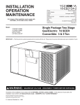
The factory ships the unit for horizontal airflow. Perform this
procedure to convert it to down airflow:
To install the unit at ground level:
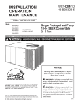
1. Place the unit on a pad the size of the unit or larger. The unit
must be mounted level for proper drainage of water through
the holes in the base pan.
The pad must not come in contact with the structure (see
Figure 7, below.) Be sure the outdoor portion of the supply
and return air ducts are as short as possible.
2. Location of the unit must allow service clearance around it.
Clearance of the unit must be given careful consideration.
See Figures 1 through 6, pages 4-9.
NOTE: Any reduction of the unit clearances indicated in
these illustrations may result in condenser coil starvation or
the recirculation of warm condenser air. Actual clearances,
which appear to be inadequate should be reviewed with a
local engineer.
3. Attach the supply and return air ducts to the unit as explained in the Ductwork Installation section (page 15).
4. Flexible duct connectors must be of a flame retardant material.
Insulate any ductwork outside of the structure with at least two
(2) inches of insulation and weatherproof. There must be a
weatherproof seal where the duct enters the structure.
5. The unit should not be exposed to direct roof water runoff.
6. Seal all holes through exterior walls in accordance with local
codes.
7. Continue with the following installation sections to complete
the installation: Ductwork (page 15), Filter (page 16), and
Electrical Wiring (page 16).
1. Remove the three (3) sheet metal screws securing the supply air
cover and the four (4) sheet metal screws securing the return air
cover from the base of the unit. Remove the covers from the base.
See Figure 8, page 12.
2. Place the covers over the horizontal supply and return openings
(painted side out). Align the screw holes, and secure using the
same screws removed in step 1.
Install Full Perimeter Roof Mounting Curb
1. Verify that the roof mounting curb is correct for the unit.
• 4WCZ6036 uses model BAYCURB050A.
• 4WCZ6048 and 4WCZ6060 use model BAYCURB051A.
2. Assemble and install the curb following the instruction in the
appropriate Installer's Guide.
Lifting and Rigging
1. Before preparing the unit for lifting, check the unit dimension
drawings for center of gravity for lifting safety (Figures 1 to 6).
Because of placement of internal components, the unit’s weight
may be unevenly distributed. Approximate unit weights are
also provided in the unit drawings.
NOTE: Unit rigging and hoisting requires accessory kit
BAYLIFT002AA. It includes a kit of four (4) lifting lugs. See
Figure 9 inset B.
NOTE: Use the extreme
mounting kit, BAYEXMK003AA,
to secure the unit to the slab.
SHIELD
ISOLATORS
(1 PER CORNER &
1 IN MIDDLE OF
EACH LONG SIDE)
Figure 7. Typical Ground Level Applications
Page 11
Installer’s Guide
Figure 8. Converting Horizontal to Down Airflow
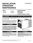
2. Insert the four (4) lifting lugs in the openings provided in the drip
lip on each end of the unit. See Figure 9 inset B, page 13. A
tap or jerk to the lug will overcome the interference that arises
due to the dimple on the lug.
3. When hoisting the unit, be sure that a proper method of rigging
is used. Use either the unit's top shipping skid and straps or
slings and spreader bars for protection during lifting. Always
test-lift the unit to determine the exact unit balance and stability
before hoisting it to the installation location.
IMPORTANT: Do not lift the unit without test lifting for balance
and rigging. Do not lift the unit in windy conditions or above
personnel. Do not lift the unit by attaching clevis, hooks, pins,
or bolts to the unit casing, casing hardware, corner lugs, angles,
tabs, or flanges. Failure to observe these warnings may result
in equipment damage.
4. When the curb and air ducts have been properly installed, the
unit is ready to be hoisted to the roof and set in position.
IMPORTANT: To prevent damage to the sides and top of the
unit when hoisting, retain the top shipping skid on the unit
or use “spreader bars” as shown on page 13.
IMPORTANT: The unit must be lowered into position. The
P.V.C. rubber tape on the curb flange permits the unit to be
repositioned if required without destroying the P.V.C. rubber
seals affixed to the mounting curb.
Placing the Unit on the Mounting Curb
1. The unit is designed with a perimeter drip lip that is lower than
the unit base pan, see Figure 9, inset A, page 13.
2. Position the unit drip lip down over and in contact with the
outside corner of the curb. Continue to lower the unit on top of
the curb, with the unit drip lip astraddle, and in contact with, both
the end and side rail of the curb. The unit should now rest on
top of the curb.
3. Take the hold-down brackets shipped with the curb (utility curb
only) and secure the unit to the curb.
Page 12
NOTE The ductwork is installed as part of the curb installation.
Do not attach ductwork to the unit and lower the unit with
ductwork onto the curb.
Rooftop Installation -- Frame Mounting
For roof top applications using a field fabricated frame and ducts,
use the following procedure:
1. Locate and secure the frame to the roof by bolting or welding.
Add flashing as required. Flashing must conform to local
building codes.
2. Prepare the hole in the roof in advance of installing the unit.
3. Secure the horizontal or down airflow ducts to the roof. Refer
to the previous Convert from Horizontal Airflow to Down Airflow
section, page 11, if conversion is needed.
4. All fabricated outdoor ducts should be as short as possible.
5. Place the unit on the frame. Refer to Figures 11 or 12, page 14.
6. The unit must be mounted level for proper drainage of water
through the holes in the base pan.
7. Secure the unit to the frame.
8. Insulate any ductwork outside of the structure with at least two
(2) inches of insulation and then weatherproof. There must be
a weatherproof seal where the duct enters the structure.
9. The unit should not be exposed to direct roof water runoff.
10. Flexible duct connectors must be of a flame retardant material.
All duct work outside of the structure must be insulated and
weatherproofed in accordance with local codes.
11. Access and service clearances for the unit must be given
careful consideration when locating the duct entrance openings. Figures 1 - 6, pages 4-9, provides unit dimensions.
12. Continue with the following installation sections to complete
the installation: Ductwork (page 15), Filter (page 16), and
Electrical Wiring (page 16).
Installer’s Guide
Base of unit
rest on top of
curb rails
Drip lip on
perimeter of
unit
IMPORTANT: To prevent damage
to the sides and top of the unit when
hoisting, retain the top shipping skid
on the unit or use “spreader bars” as
shown in these illustrations.
Spreader Bars
Unit Corner
Curb Corner
Top shipping skid
attached to unit
Gasket Seal
Drip Lip
Dimple
BAYLIFT002A
Lifting Lugs
Figure 9. Lifting and Rigging
This drawing was prepared by the manufacturer in order to provide detail regarding job layout only. This drawing is
not intended to be used as a basis to construct, build or modify the item depicted in the drawing. The manufacturer
is not responsible for the unauthorized use of this drawing and expressly disclaims any liability for damages
resulting from such unauthorized use.
Figure 10. Curb Dimensions
Page 13
Installer’s Guide
Figure 11. Typical Rooftop Horizontal Airflow Application with Frame
Figure 12. Typical Rooftop Down Airflow Application with Frame
Page 14
Installer’s Guide
Ductwork Installation
Attaching Downflow Ductwork to Roof Curb
UNIT EXTERIOR
Supply and return air flanges are provided on the roof curb for easy
duct installation. All ductwork must be run and attached to the curb
before the unit is set into place.
WEATHERPROOF
THIS SEAM
FIELD DUCT
Attaching Downflow Ductwork to Roof Frame
Follow these guidelines for ductwork construction:
Connections to the unit should be made with three (3) inch canvas
connectors to minimize noise and vibration transmission.
UNIT EXTERIOR
WEATHERPROOF
THIS SEAM
Elbows with turning vanes or splitters are recommended to minimize air noise and resistance.
FIELD DUCT
The first elbow in the ductwork leaving the unit should be no closer
than two (2) feet from the unit, to minimize noise and resistance.
Figure 14. Attaching Horizontal Airflow Ductwork
To prevent leaking, do not attach the ductwork to the bottom of the
unit base. Refer to the bottom example in Figure 13, below.
AIR PROOF
THIS SEAM
Condensate Drain Piping
UNIT BASE
FIELD DUCT
UNIT DUCT
FLANGE
A 3/4-inch female NPT condensate drain connection is provided on
the evaporator access panel end of the unit. Provide a trap and fill
it with water before starting the unit to avoid air from being drawn
through. Follow local codes and standard piping practices when
running the drain line. Pitch the line downward away from the unit.
Avoid long horizontal runs. See Figure 15, below.
AIR PROOF
THIS SEAM
UNIT DUCT
FLANGE
NOTE: Do not use reducing fittings in the drain lines.
UNIT BASE
FIELD DUCT
AIR PROOF
THIS SEAM
The condensate drain must be:
●
Made of 3/4" pipe size.
●
Pitched 1/4" per foot to provide free drainage to convenient drain
system.
●
Trapped.
●
Must not be connected to a closed drain system unless the trap
is properly vented.
UNIT BASE
FIELD
DUCT
UNIT DUCT FLANGE
UNIT BASE
UNIT DUCT
FLANGE
NOT RECOMMENDED
WATERPROOF SEAM
WITH BUTYL OR
SILICONE
FIELD DUCT
DOWNFLOW
Figure 13. Attaching
Down Airflow Ductwork
3/4" PVC OR COPPER
TUBING AND FITTINGS
1-1/2" MIN.
Attaching Horizontal Ductwork to Unit
All conditioned air ductwork should be insulated to minimize
heating and cooling duct losses. Use a minimum of two (2) inches
of insulation with a vapor barrier. The outside ductwork must be
weatherproofed between the unit and the building.
When attaching ductwork to a horizontal unit, provide a flexible
watertight connection to prevent noise transmission from the unit to
the ducts. The flexible connection must be indoors and made out
of heavy canvas.
1-1/2" MIN.
Figure 15. Typical Condensate Drain Piping
NOTE: Do not draw the canvas taut between the solid ducts.
Page 15
Installer’s Guide
To connect power to the unit:
Air Filter Installation
The 4WCZ6 heating/cooling unit requires an air filter. A filter frame
accessory is offered that will allow the installation of a filter within
the unit.
Otherwise a filter rack must be installed by the installer in the return
duct work.
Affix the filter label supplied with the unit adjacent to the filter area.
Refer to Table 1 to determine filter size.
Table 1. Determine Filter Size
NOMINAL
CFM
FILTER* SIZE
(Sq. Ft.)
FILTER
RESISTANCE
("W.C.")
4WCZ6036
1200
4
0.08
4WCZ6048
1600
5.33
0.08
4WCZ6060
2000
6.67
0.08
UNIT
1. Remove the Control access panel. Pass the power
wires through the Power Entry hole in the end of the unit.
See Figure 16 below.
2. Connect the high voltage wires to the appropriate contactor
terminals. Single phase units use a two (2) pole contactor
and three phase units use a three (3) pole contactor. Connect
the ground to the ground lug on the chassis. See Figure 17
below. Be sure all connections are tight.
GROUNDING: THE UNIT MUST BE ELECTRICALLY
GROUNDED IN ACCORDANCE WITH LOCAL CODES OR
THE NATIONAL ELECTRIC CODE.
Run power supply
lines through
weather-tight conduit
and secure to unit
with strain relief
*Filters must be installed in the return air system. The above square
footages are based on 300 F.P.M. face velocity. If permanent filters are
used, size per mfg. Recommendation with clear resistance of 0.05"WC.
24V Entry
Power Entry
Power Entry
Electrical Wiring
Single Pointy Entry
(use with Single
Power Entry Kit)
NOTE: This unit is factory wired for 230V. See wiring diagram
for 208V conversion.
Electrical Connections
Electrical wiring and grounding must be installed in accordance
with local codes or, in the absence of local codes, with the National
Electrical Code ANSI/NFPA 70, Latest Revision.
Electrical Power
It is important that proper electrical power be available for the unit.
Voltage variation should remain within the limits stamped on the
unit's nameplate.
Control
Access Panel
Figure 16. Power Wiring
Disconnect Switch
Provide an approved weatherproof disconnect within close proximity and within sight of the unit.
Over Current Protection
The branch circuit feeding the unit must be protected as shown on
the unit's nameplate.
Contactor
Power Wiring
The power supply lines must be run in weather-tight conduit to the
disconnect and into the side of the unit control box. Provide strain
relief for all conduit with suitable connectors.
NOTE: For branch circuit wiring (main power supply to unit
disconnect), determine wire size for the length of run using the
circuit ampacity found on the unit's nameplate and the N.E.C.
For more than three (3) conductors in a raceway or cable, see
the N.E.C. for derating the ampacity of each conductor.
Provide flexible conduit supports whenever vibration transmission
may cause a noise problem within the building structure.
For units that are configured for single point entry, refer to the
appropriate Single Power Entry Kit Installer's Guide to connect
power.
For units that are configured with supplemental heat, refer to the
appropriate Supplemental Electric Heater Installer's Guide to
connect heater power.
Page 16
Unit Ground Lug
Figure 17. Power Connections
Installer’s Guide
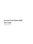
NOTES:
1. FUSED DISCONNECT SIZE, POWER WIRING AND
GROUNDING OF EQUIPMENT MUST COMPLY WITH
CODES.
2. BE SURE POWER SUPPLY AGREES WITH
EQUIPMENT AND HEATER NAMEPLATE.
3. LOW VOLTAGE WIRING TO BE 18 AWG MINIMUM
CONDUCTOR.
4. SEE HEATER NAMEPLATE FOR CURRENT RATING
OF HEATER USED.
5. SEE UNIT AND HEATER DIAGRAM FOR
ELECTRICAL CONNECTION DETAILS.
6. IF ELECTRIC HEATER ACCESSORY IS NOT
INSTALLED OMIT THE ELECTRIC HEATER,
ASSOCIATED POWER WIRES AND THE W AND X2
THERMOSTAT WIRES.
7. FIG. 2 DEMONSTRATES CONNECTION OF THE
OUTDOOR THERMOSTAT ACCESSORY ONLY. FOR
FURTHER UNIT CONNECTION DETAILS REFER TO
THE OTHER FIGURES.
8. THE W1 (WH) WIRE IS FIRST STAGE ELECTRIC
HEAT. IF THE ELECTRIC HEATER ACCESSORY
HAS TWO HEATING STAGES THE W2 (WH) WIRE IS
SECOND STAGE ELECTRIC HEAT.
9. THE BAYSTAT033A OUTDOOR THERMOSTAT
ACCESSORY KIT CONTAINS A THERMOSTAT AND
A RELAY. THE RELAY IS NOT REQUIRED TO BE
USED IN THIS APPLICATION.
9
9
Figure 18. WC Field Wiring Diagram
Page 17
Installer’s Guide
o Are all covers and access panels in place to prevent air loss and
Control Wiring (Class II)
Low voltage control wiring should not be run in conduit with power
wiring unless Class 1 wire of proper voltage rating is used. Route
the thermostat cable or equivalent single leads of No. 18 AWG
colored wire from the thermostat subbase terminals through the
rubber grommet on the unit. See Figures 1-6 (pages 4-9) for the
control entry (24V Entry) location. Make connections as shown on
the field wiring diagram Figure 18, page 17.
Do not short thermostat wires since this will damage the control
transformer.
Refer to Table 2 for recommended wire sizes and lengths for
installing the unit thermostat. The total resistance of these low
voltage wires must not exceed one (1) ohm. Any resistance in
excess of 1 ohm may cause the control to malfunction because of
the excessive voltage drop.
Table 2. Thermostat Wire Size and Maximum Length
WIRE SIZE
18
16
14
MAXIMUM LENTGH (Ft)
75
125
200
Step 5—Unit Startup
Pre-Start Quick Checklist
o Is the unit properly located and level with the proper
clearance? See Figures 1-6, pages 4-9. See Step 2-Review
Location and Clearances on page 4.
o Is the duct work correctly sized, run, taped, insulated, and
See
o Is the condensate line properly sized, run, trapped, and
pitched? See Condensate Drain Piping section on page
15.
o Is the filter of the correct size and quantity? Is it clean and in
place? See Air Filter Installation section on page 16.
o Is the wiring properly sized and run according to the unit
wiring diagram? See Electrical Wiring section on page 16.
o Are all the wiring connections, including those in the unit,
tight? See Electrical Wiring section on page 16.
o Has the unit been properly grounded and fused with the
recommended fuse size? See Electrical Wiring section on
page 16.
o Is the thermostat well located, level, and correctly wired?
See Electrical Wiring section on page 16.
o Have the air conditioning systems been checked at the service
ports for charge and leak tested if necessary?
o Do the condenser fan and indoor blower turn free without
rubbing, and are they tight on the shafts?
o Has all work been done in accordance with applicable local
and national codes?
Page 18
Starting the Unit in Cooling Mode
! WARNING
▲
Safety Hazard. Do not operate the unit without the evaporator
fan access panel or evaporator coil access panel in place.
Reinstall the access panels after performing maintenance
procedures on the fan. Operating the unit without the access
panels properly installed may result in severe personal injury
or death.
! CAUTION
▲
Before starting the system on the cooling cycle, turn the thermostat switch to OFF and close the unit disconnect switch. This is
a precaution against foaming at startup which could damage the
compressor bearings.
NOTE: See the section on Sequence of Operation , page 19 for
a description of the cooling operating sequence.
IMPORTANT: Upon completion of wiring, check all electrical
connections, including factory wiring within the unit, and make sure
all connections are tight. Replace and secure all electrical box
covers and access panels before leaving the unit or turning on the
power to the unit.
weatherproofed with proper unit arrangement?
Ductwork Installation section on page 15.
safety hazards?
To start the unit in the cooling mode, set the thermostat system
switch to COOL and move the thermostat COOL indicator to a
setting below room temperature. The condenser fan motor,
compressor and evaporator fan motor will operate automatically.
Operating Pressure Checks
After the unit has operated in the cooling mode for a short period of
time, install pressure gauges on the gauge ports of the discharge
and suction line valves (behind the Compressor access panel).
Check the suction and discharge pressures and compare them to
the normal operating pressures provided in the unit’s SERVICE
FACTS.
NOTE: Do not use the pressures from the unit's SERVICE
FACTS to determine the unit refrigerant charge. The correct
charge is shown on the unit nameplate. To charge the system
accurately, weigh in the charge according to the unit nameplate.
Voltage Check
With the compressor operating, check the line voltage at the unit
(contactor is located behind the Control access panel). The voltage
should be within the range shown on the unit nameplate. If low
voltage is encountered, check the size and length of the supply line
from the main disconnect to the unit. The line may be undersized
for the length of the run.
Cooling Shut Down
At the thermostat, set the system selector to OFF or reset the
thermostat to a setting above room temperature.
Starting the Unit in Heating Mode
NOTE: See the section on Sequence of Operation for a description of the heat pump heating operating sequence.
Check that all grills and registers are open and all unit access
panels are closed before start-up.
Set the thermostat above room temperature, achieving a first
stage call for heat, and set the fan to AUTO or ON.
Heating Shut Down
Set the thermostat to OFF or place the heating selector at a setting
below room temperature.
Installer’s Guide
Sequence of Operation
General
Operation of the unit heating and cooling cycles is automatic when
the system is set to HEAT or COOL (the optional automatic
changeover thermostat, when set to AUTO, automatically changes
to heat or cool with an appropriate room temperature change). The
fan can be set to ON, causing continuous evaporator (indoor) fan
operation or set to AUTO causing fan operation to coincide with
heating or cooling run cycles. Continuous fan mode during cooling
operation may not be appropriate in humid climates. If the indoor
air exceeds 60% relative humidity or simply feels uncomfortably
humid, it is recommended that the fan only be used in the AUTO
mode. With the thermostat set to ON current is supplied to the
control transformer (on 460v models the outdoor fan relay (ODF)
is energized through normally closed contacts on the defrost
control (DFC).
COOLING MODE
Thermostat call for cooling (2-stage thermostat)
Call for 1st stage cooling only:
With the room thermostat set to COOL and the fan set to AUTO,
power is supplied from the room thermostat “O” terminal to the
unit switchover valve coil (SOV) and the “O” terminal on the
ECMC board. This energizes the switch-over valve (SOV)
placing it in the position for cooling (it is in the position for
heating when de-energized). On a call for cooling, power is
supplied to the unit from the room thermostat (Y1) and (G)
terminal. (Y1) provides power to the compressor contactor
(CC), the defrost control (DFC) and the electronically
commutated motor control (ECMC). (G) provides power to the
(ECMC) for low speed (IDM) indoor fan motor operation.
The energized compressor contactor (CC) completes the
circuit to the compressor for 1st stage (Low) operation and the
outdoor single speed fan motor (ODM). The (G) signal
energizes the (ECMC) for the indoor fan motor (ECM) to
operate on low speed. The thermostat will continue to cycle the
compressor and fans to maintain the desired temperature.
Call for 2nd stage after 1st stage
On a call for 2nd stage cooling, power is supplied from the
room thermostat (Y2) terminal to the A/C rectifier (ACR) and
the (ECMC). This energizes the (ACR) switching the
compressor to 2nd stage (High) operation. The (ECMC) is
energized for indoor fan motor (ECM) high speed fan
operation. The room thermostat will continue to cycle the
system between 1st and 2nd stage to maintain the desired
temperature.
HEATING MODE
Thermostat call for heat (2-stage thermostat)
Call for 1st stage heating only:
With the room thermostat set to HEAT and the fan set to AUTO,
no power is supplied from the room thermostat “O” terminal to
the unit switchover valve coil (SOV) and the “O” terminal on the
ECMC board. This leaves the switch-over valve (SOV) in the
normal position for heating and is the signal for the (ECMC) to
run at indoor fan speeds designed for heating. On a call for
heating, power is supplied to the unit from the room thermostat
(Y1) and (G) terminal. (Y1) provides power to the compressor
contactor (CC), the defrost control (DFC) and the electronically
commutated motor control (ECMC). (G) provides power to the
(ECMC) for low speed (ECM) indoor fan motor operation.
The energized compressor contactor (CC) completes the
circuit to the compressor for 1st stage (Low) operation and
the outdoor single speed fan motor (ODM). The indoor fan
motor (ECM) will operate on low speed. The room thermostat
will continue to cycle the compressor and fans to maintain
the desired temperature.
Call for 2nd stage after 1st stage
On a call for 2nd stage heating, power is supplied from the
room thermostat (Y2) terminal to the compressor rectifier
(ACR) and the (ECMC). This energizes the (ACR) switching
the compressor to 2nd stage (High) operation. The (ECMC) is
energized for indoor fan motor (ECM) high speed fan
operation. The room thermostat will continue to cycle the
system between 1st and 2nd stage to maintain the desired
temperature.
Supplementary Heat
The supplementary electric heat is brought on when the indoor
temperature drops below the thermostat setting. The thermostat
provides power from the “W” terminal to the supplementary
heater control circuit. Note that the fan relay (F) must have been
energized. An outdoor thermostat may have been added to
disallow the second stage (if provided) of electric heat above a
selected outdoor temperature. If the outdoor temperature falls
below the setting on the outdoor thermostat, this additional
heater stage will come on. When the outdoor air temperature
rises, and the outdoor T-stat setpoint is reached, the system will
revert back to first stage electric heating.
When the indoor ambient is satisfied, "W" contacts will open and
the unit will revert back to the compressor only heating mode and
then off. For emergency heat (use of supplementary electric heat
only), an emergency (EMERG) heat switch is provided within the
thermostat. When placed in the emergency heat position, it will
disable the compressor, bypass the outdoor thermostats, if
provided, and engage the supplementary electric heaters and
indoor fan.
Demand Defrost Operation
During the heating cycle, the outdoor coil may require a defrost
cycle which is determined by the demand defrost control (DFC).
This control continuously measures the outdoor coil temperature
(CBS) and the outdoor ambient temperature (ODS-B) and calculates the difference or delta-T measurement. When the calculated
delta-T is met, the demand defrost control (DFC) opens the circuit
to the outdoor fan motor (ODM) and energizes the switch-over valve
(SOV), placing the unit in the cooling mode to defrost the outdoor
coil (on SCROLL bearing units only, the control will stop the
compressor for a minimum of thirty (30) seconds). The outdoor coil
temperature sensor (CBS) terminates the defrost cycle, or it times
off after twelve (12) minutes in defrost, the (DFC) energizes the
outdoor fan motor (ODM) and twelve seconds later de-energizes
the (SOV), which returns the unit to the heating mode. Supplementary electric heat, if provided, is brought on to control indoor
temperature during the defrost cycle. During this defrost cycle the
indoor fan will run at the speed designated for 2nd stage cooling.
Defrost Control
The demand defrost control measures heat pump outdoor
ambient temperature with a sensor located outside the outdoor
coil. A second sensor located on the outdoor coil is used to
measure the coil temperature. The difference between the
ambient and the colder coil temperature is the difference or
delta-T
measurement.
This
delta-T
measurement
is
representative of the operating state and relative capacity of the
heat pump system. Measuring the change in delta-T
determines the need for defrost. The coil sensor also senses
outdoor coil temperature for termination of the defrost cycle.
Page 19
Installer’s Guide
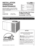
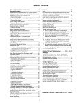
ECM Fan Motor Adjustments
If the airflow needs to be increased or decreased, see the
Airflow Table in the SERVICE FACTS. Information on changing
the speed of the blower motor is in the Blower Performance
Table. Blower speed changes are made on the ECM Fan
Control mounted in the control box. The ECM Fan Control
controls the variable speed motor. There is a bank of 8 dip
switches, (See Figure 19 below), located on the board. The dip
switches work in pairs to match the cooling/heat pump airflow
(CFM/TON), Fan off-delay options and electric heat airflow
adjustment. The unit ships with dip switches defaulted as
shown below.
CFM
SELECTION
LIGHT
DIP
SWITCHES
Maintenance
Owner Maintenance
Some of the periodic maintenance functions of the 4WCZ6 unit can
be performed by the owner; this includes replacing the disposable
or cleaning the permanent air filters, cleaning the unit cabinet,
cleaning the condenser coil, and conducting a general unit inspection on a regular basis.
Filters
When the system is in constant operation, inspect the filters at
least once each month.
If the unit has disposable-type filters, replace them with new filters
of the same type and size. Do not attempt to clean disposable
filters.
Permanent-type filters can be cleaned by washing them with a mild
detergent and water. Make sure that the filters are thoroughly dry
before reinstalling them in the unit (or duct system).
NOTE: It may be necessary to replace permanent filters
annually if washing fails to clean the filter or if the filter shows
signs of deterioration. Be sure to use the same type and size
as was originally installed.
Condenser Coil
Be sure to keep all vegetation and debris away from the condenser
coil area.
Figure 19. ECM Fan Control
Service Maintenance
Cooling Season
Final Installation Checklist
o Does the unit run and operate as described in the section on
Sequence of Operation, page 19, in response to the room
thermostat?
o Are the condenser fan and indoor blower operating correctly
with proper rotation and without undue noise?
o Is the compressor operating correctly and has the system been
checked with a charging chart?
o Has the voltage and running current been checked to deter
mine if it is within limits?
o Has the thermostat been checked for calibration and the air
discharge grills adjusted to balance the system?
o Has the ductwork been checked for air leaks and
condensation?
o Has the furnace manifold pressure been checked and
adjusted if necessary?
o Has the heating air temperature rise been checked?
o Has the unit been checked for tubing and sheet metal rattles?
Are there any other unusual noises to be checked?
o Are all covers and panels in place and properly fastened?
o Has the owner been instructed on the proper operation and
maintenance of the unit? Be sure to leave this manual with the
owner.
Page 20
To keep the unit operating safely and efficiently, the manufacturer
recommends that a qualified service technician check the entire
system at least once each season or sooner if needed. The service
technician should examine these areas of the 4WCZ6 unit:
● filters (for cleaning or replacement)
● motors and drive system components (for proper operation)
● economizer gaskets (for possible replacement)
● safety controls (for mechanical cleaning)
● electrical components and wiring (for possible replacement and
connection tightness)
● condensate drain (for proper sealing and cleaning)
● unit duct connections (to see that they are physically sound and
sealed to the unit casing)
● unit mounting support (for structural integrity)
● the unit (for obvious unit deterioration)
Heating Season
Complete the following unit inspections and service routines at the
beginning of each heating season.
● Visually inspect the unit to ensure that the airflow required for
combustion and condenser coil is not obstructed from the unit.
● Inspect the control panel wiring to verify that all electrical connections are tight and that the wire insulation is intact.
Installer’s Guide
Limited Warranty
High Efficiency Heat Pump
4WCZ6, 4WCY4, 2/4WCX3 and WCZ
(Parts Only)
Models Less Than 20 Tons for Residential Use*
This limited warranty is extended by Trane U.S. Inc., to the original purchaser and to any succeeding owner of the real
property to which the Heat Pump is originally affixed, and applies to products purchased and retained for use within
the U.S.A. and Canada.
If any part of your Heat Pump fails because of a manufacturing defect within five years from the date of the original
purchase, Warrantor will furnish without charge the required replacement part. Any local transportation, related service labor, diagnosis calls, refrigerant and related items are not included.
In addition, if the sealed motor-compressor(s) fail(s) or the outdoor coil† should become defective, either or both
events occurring because of a manufacturing defect within the sixth through tenth year from the date of original
purchase, Warrantor will furnish without charge the required replacement compressor and/or outdoor coil. Any local
transportation, related service labor, diagnosis calls, refrigerant and related items are not included.
†
NOTE: If your Heat Pump is installed within one mile of salt water, including but not limited to seacoasts and inland
waterways, your outdoor coil warranty as stated above is limited to five years from the date of original purchase.
This limited warranty does not cover failure of your Heat Pump if it is damaged while in your possession, damage
caused by unreasonable use of the Heat Pump and/or damage from failure to properly maintain the Heat Pump as
set forth in the Use and Care manual (see Proper Maintenance section).
THE LIMITED WARRANTY AND LIABILITY SET FORTH HEREIN ARE IN LIEU OF ALL OTHER WARRANTIES AND LIABILITIES, WHETHER IN CONTRACT OR IN NEGLIGENCE, EXPRESS OR IMPLIED,
IN LAW OR IN FACT, INCLUDING BUT NOT SPECIFICALLY LIMITED TO IMPLIED WARRANTIES OF
MERCHANTABILITY AND FITNESS FOR PARTICULAR USE, AND IN NO EVENT SHALL WARRANTOR BE LIABLE FOR ANY INCIDENTAL OR CONSEQUENTIAL DAMAGES.
Some states do not allow limitations on how long an implied limited warranty lasts or do not allow the exclusion or limitation of incidental or consequential damages, so the above limitation or exclusion may not apply to you. This limited
warranty gives you specific legal rights, and you may also have other rights which vary from state to state.
Parts will be provided by our factory organization through an authorized service organization in your area listed in the
yellow pages. If you wish further help or information concerning this limited warranty, contact:
Trane
P. O. Box 9010, Tyler, TX 75711-9010
Attention: Manager, Field Operations Excellence
Or visit our website: www.trane.com/residential
TW-1003-4707
* This limited warranty is for residential usage of this equipment and not applicable when this equipment is used for a
commercial application. A commercial use is any application where the end purchaser uses the product for other than
personal, family or household purposes.
The limited warranties displayed in this publication and/or on ComfortSite™
may not accurately reflect the actual limited warranty that shipped with the
product.
9
26-1000-21
Page 21
Installer’s Guide
Limited Warranty
High Efficiency Heat Pump
4WCZ6, 4WCY4, 2/4WCC3, 2/4WCX3,
WCZ, WCD, WCH, WCK, WSC (Parts Only)
Models Less Than 20 Tons for Commercial Use*
This warranty is extended by Trane U.S. Inc., to the original purchaser and to any succeeding owner of the real property to which the Heat Pump is originally affixed, and applies to products purchased and retained for use within the
U.S.A. and Canada. There is no warranty against corrosion, erosion or deterioration.
If any part of your Heat Pump fails because of a manufacturing defect within one year from the date of the original
purchase, Warrantor will furnish without charge the required replacement part.
In addition, if the sealed motor-compressor fails because of a manufacturing defect within the second through fifth
year from the date of original purchase, Warrantor will furnish without charge the required replacement compressor.
Warrantor’s obligations and liabilities under this warranty are limited to furnishing F.O.B. Warrantor factory or warehouse replacement parts for Warrantor’s products covered under this warranty. Warrantor shall not be obligated to pay
for the cost of lost refrigerant. No liability shall attach to Warrantor until products have been paid for and then liability
shall be limited solely to the purchase price of the equipment under warranty shown to be defective.
THE WARRANTY AND LIABILITY SET FORTH HEREIN ARE IN LIEU OF ALL OTHER WARRANTIES AND LIABILITIES, WHETHER IN CONTRACT OR IN NEGLIGENCE, EXPRESS OR IMPLIED, IN
LAW OR IN FACT, INCLUDING IMPLIED WARRANTIES OF MERCHANTABILITY AND FITNESS FOR
PARTICULAR USE, AND IN NO EVENT SHALL WARRANTOR BE LIABLE FOR ANY INCIDENTAL OR
CONSEQUENTIAL DAMAGES.
Some states do not allow limitations on how long an implied warranty lasts or do not allow the exclusion or limitation
of incidental or consequential damages, so the above limitation or exclusion may not apply to you. This warranty gives
you specific legal rights, and you may also have other rights which vary from state to state.
Trane
P.O. Box 9010
Tyler, TX 75711-9010
Attention: Manager, Field Operations Excellence
TW-1005-4707
* This warranty is for commercial usage of said equipment and not applicable when the equipment is used for a
residential application. Commercial use is any application where the end purchaser uses the product for other than
personal, family or household purposes.
The limited warranties displayed in this publication and/or on ComfortSite™
may not accurately reflect the actual limited warranty that shipped with the
product.
Page 22
11
26-1000-21
Installer’s Guide
Page 23
Installer’s Guide
Trane
6200 Troup Highway
Tyler, TX 75707-9010
© 2008 Trane
Page 24
The manufacturer has a policy of continuous product and product data improvement,
and it reserves the right to change design and specification without notice.