1
COMMUNICATION MANUAL
Universal Digital Controller
C10
M10 – M300 – M400 – M5000
X100 – X400 – X5000 – X7000
ATHENA CONTROLS, INC.
5145, Campus Drive
Plymouth Meeting
Pennsylvania 19462-1129 U.S.A
Copyright 1996 Athena Controls
All rights reserved
No part of this document may be stored in a retrieval system, or
transmitted in any form, electronic or mechanical, without prior written
permission of Athena Controls.
Athena Controls has used the best care and efforts in preparing this book
and believes the information in this publication are accurate. The Athena
Controls Products are subjected to continuous improvement, in the
pursuit the technological leadership, these improvements could require
changes to the information of this book. ATHENA CONTROLS reserves
the right to change such information without notice.
ATHENA CONTROLS makes no warranty of any kind, expressed or
implied, with regard to the documentation contained in this book.
ATHENA CONTROLS shall not be liable in any event - technical and
publishing error or omissions - for any incidental and consequential
damages, in connection with, or arising out of the use of this book.
AC STATION, AC PROGRAPH e AC EDIT, are trademarks of
ATHENA
CONTROLS.
All the other tradenames or product name are trademark or registered
trademarks.
2
C
O
N
T
E
N
T
S
1.
MODBUS PROTOCOL....................................................................................................................................6
2.
MESSAGE FORMAT.......................................................................................................................................6
2.1
CHARACTERS FORMAT .................................................................................................................................7
2.2
THE ADDRESS...............................................................................................................................................7
2.3
THE FUNCTION CODE ...................................................................................................................................7
2.4
THE CRC 16 ALGORITHM ............................................................................................................................7
2.4.1
CRC 16 Flow Chart .............................................................................................................................9
2.4.2
Visual Basic Calculate CRC16 example............................................................................................10
2.5
MESSAGE SYNCHRONISATION ....................................................................................................................10
3.
THE MODBUS FUNCTIONS........................................................................................................................10
3.1
3.2
3.3
3.4
3.5
3.6
3.7
3.8
3.9
4.
ERROR MANAGEMENT..............................................................................................................................14
4.1
5.
ERROR CODES ............................................................................................................................................15
MODBUS ON ATHENA CONTROLS PLATINUM® INSTRUMENTS .................................................15
5.1
5.2
5.3
5.4
5.5
5.6
6.
READ OUTPUT STATUS (01) .......................................................................................................................10
READ INPUT STATUS (02)...........................................................................................................................11
READ OUTPUT REGISTERS (03) ..................................................................................................................11
READ INPUT REGISTERS (04)......................................................................................................................11
FORCE SINGLE COIL (05)............................................................................................................................12
PRESET SINGLE REGISTER (06)...................................................................................................................12
READ STATUS (07) .....................................................................................................................................13
FORCE MULTIPLE COILS (15) .....................................................................................................................13
PRESET MULTIPLE REGISTERS (16) ............................................................................................................14
SERIAL COMMUNICATIONS PARAMETERS ....................................................................................................15
COMMUNICATIONS TIME .............................................................................................................................15
DATA BASE ................................................................................................................................................16
BIT ZONE ....................................................................................................................................................16
WORD ZONE ...............................................................................................................................................16
ASSIGNMENT OF THE PARAMETERS AND E2PROM .....................................................................................17
ELECTRICAL CONNECTIONS ..................................................................................................................17
6.1
GENERAL DESCRIPTION ..............................................................................................................................17
6.2
COMMUNICATION CABLE LAYING RECOMMENDATIONS ............................................................................18
6.3
INSTRUMENTS WITH AN RS-485 INTERFACE (2 WIRE) ................................................................................18
6.3.1
References..........................................................................................................................................19
7.
C10 / M10 CONTROLLERS..........................................................................................................................19
7.1
7.2
7.3
7.4
7.5
8.
BIT ZONE ....................................................................................................................................................19
READ STATUS .............................................................................................................................................20
WORD ZONE - PAGE 1 PARAMETERS ..........................................................................................................20
WORD ZONE - PAGE 2 CONFIGURATION .....................................................................................................21
TERMINATION AND POLARISATION .............................................................................................................22
M300 CONTROLLER ....................................................................................................................................22
8.1
8.2
8.3
8.4
8.5
BIT ZONE ....................................................................................................................................................22
READ STATUS .............................................................................................................................................23
WORD ZONE - PAGE 1 PARAMETERS ..........................................................................................................23
WORD ZONE - PAGE 2 CONFIGURATION .....................................................................................................24
TERMINATION AND POLARISATION .............................................................................................................26
3
M400 CONTROLLER ....................................................................................................................................27
9.
9.1
9.2
9.3
9.4
9.5
10.
10.1
10.2
10.3
10.4
10.5
10.6
11.
11.1
11.2
11.3
11.4
11.5
11.6
11.7
12.
12.1
12.2
12.3
12.4
12.5
12.6
13.
BIT ZONE ....................................................................................................................................................27
READ STATUS .............................................................................................................................................27
WORD ZONE - PAGE 1 PARAMETERS ..........................................................................................................27
WORD ZONE - PAGE 2 CONFIGURATION .....................................................................................................28
TERMINATION AND POLARIZATION.............................................................................................................31
M5000 CONTROLLER ..............................................................................................................................31
BIT ZONE ....................................................................................................................................................31
READ STATUS .............................................................................................................................................32
WORD ZONE - PAGE 1 PARAMETERS ..........................................................................................................32
WORD ZONE - PAGE 2 CONFIGURATION .....................................................................................................33
WORD ZONE - PAGE 3 PROGRAMMER .........................................................................................................34
RS-485 CONFIGURATION DIP SWITCH .......................................................................................................39
X100 / X400 CONTROLLER.....................................................................................................................39
BIT ZONE ....................................................................................................................................................39
READ STATUS .............................................................................................................................................40
WORD ZONE - PAGE 1 PARAMETERS ..........................................................................................................40
WORD ZONE - PAGE 2 PARAMETERS ..........................................................................................................41
WORD ZONE - PAGE 3 PROGRAM ...............................................................................................................42
WORD ZONE - PAGE 4 CONFIGURATION .....................................................................................................42
RS-485 CONFIGURATION DIP SWITCH .......................................................................................................46
X5000 CONTROLLER...............................................................................................................................47
BIT ZONE ....................................................................................................................................................47
READ STATUS .............................................................................................................................................47
WORD ZONE - PAGE 1 PARAMETERS ..........................................................................................................48
WORD ZONE - PAGE 2 CONFIGURATION .....................................................................................................49
WORD ZONE - PAGE 3 PROGRAMMER .........................................................................................................50
RS-485 CONFIGURATION DIP SWITCH .......................................................................................................61
CONFIGURATION SOFTWARE FOR PLATINUM CONTROLLERS .............................................61
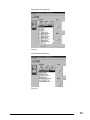
13.1 USE OF INSTRUMENTS WITH THE RS 485 COMMUNICATIONS OPTION .........................................................62
13.2 TO LOAD THE SOFTWARE ............................................................................................................................63
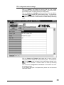
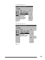
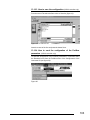
13.3 TO ENTER THE CONFIGURATION SOFTWARE ...............................................................................................64
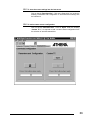
13.4 CONFIGURATION SOFTWARE SETTINGS .......................................................................................................65
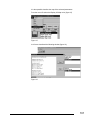
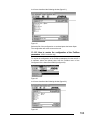
13.5 TO STORE THE SCREEN SETTINGS INTO THE INSTRUMENT............................................................................66
13.6 TO LOAD A CUSTOM SENSOR CONFIGURATION ............................................................................................66
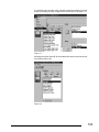
13.7 TO CLONE SEVERAL INSTRUMENTS .............................................................................................................68
13.8 TO STORE THE SCREEN SETTINGS AS A FILE.................................................................................................68
13.9 TO RECALL A PREVIOUSLY STORED FILE .....................................................................................................69
13.10
PRINTING OF THE CONFIGURATION .........................................................................................................70
13.11
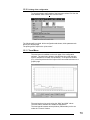
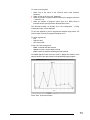
TREND MENU .........................................................................................................................................70
13.12
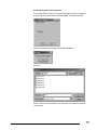
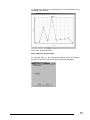
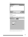
PROGRAMMED SETPOINT (ONLY IF THE PROGRAM OPTION IS PRESENT) .....................................................71
13.12.1
M5000 Controller ..........................................................................................................................71
13.12.2
X400 Controller .............................................................................................................................77
13.12.3
X5000 Controller ...........................................................................................................................82
13.13
CONFIGURATION OF THE MASTER COMMUNICATIONS (ONLY X5000) ....................................................88
13.14
CONFIGURATION OF THE MATHEMATICAL / LOGICS OPERATIONS............................................................90
13.15
CONFIGURATION OF THE NUMERICAL CONSTANTS ..................................................................................92
13.15.1
To modify the value of a constant ..................................................................................................93
13.15.2
To eliminate a constant..................................................................................................................94
13.15.3
Reading/writing of the configuration of the mathematical packet in the device............................94
13.15.4
Save the configuration of the mathematical packet on files ..........................................................94
13.16
DEFINITION OF THE PROFIBUS PARAMETERS (X5000 CONTROLLER ONLY) ...............................................94
13.16.1
How to insert the parameters in the configuration (X5000 controller only) ...............................95
4
Parameters of the Data Base (X5000 controller only) ..................................................................97
13.16.2
13.16.3
How to save the configuration (X5000 controller only) ..............................................................103
13.16.4 How to send the configuration of the Profibus parameters (X5000 controller only)...............................103
13.16.5 How to receive the configuration of the Profibus parameters (X5000 controller only) ...............................104
14.
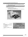
RECOMMENDED RS-232 TO RS-485 CONVERTER ........................................................................106
14.1 ATHENA PART# 223A001401 RS-232 TO RS-485 OPTICALLY ISOLATED COMMUNICATIONS CONVERTER 106
14.2 GENERAL INFORMATION ..............................................................................................................................107
5
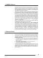
1. MODBUS Protocol
The Modbus protocol defines the format and method of communications
between a “master” which controls the system and one or more “slaves”
which respond to commands sent by the master. The Modbus defines
how the transmitter and reciever are identified, how messages are
exchanged and how errors are detected.
There may be one master and up to 247 slaves on a common line; this is
the protocol’s logical limit, the physical interface may limit the number of
devices further, for example, the standard RS485 interface handles a
maximum of 31 slaves connected on the line. Substituting the last device
on the line with a proper “repeater” or “bridge”, another 31 instruments
can be added to the line and so on up to the above mentioned limit (247).
All transactions are started by the master. A transaction may be a direct
question/reply to a single slave or broadcast in which the message is
sent to all the devices on the line and no answer is given. A transaction
consists of a single question/replay frame or a single broadcast
message/no answer frame.
Some of the characteristics of the protocol are not defined. These are:
standard interface, baud rate parity, number of bits.
The protocol also enables the user to choose between two
communications modes, ASCII and RTU (binary). Only the RTU mode is
implemented on ATHENA CONTROLS instruments as it is more efficient.
The Jbus protocol is functionally identical to Modbus and differs from it in
how the addresses are numbered: with Modbus the addresses are
numbered starting from zero) 0000= 1st address, while with Jbus they
start from one (0001=1st address). This difference is maintained
throughout all addresses. From here on, unless explicitly specified, even
though reference is made to Modbus, the description is valid for both.
2. Message Format
For communication to take place between the two devices, the message
must be put in a "packet". The packet leaves the transmitter through a
"port" and is "carried" along the line to a similar "port" on the receiver.
MODBUS establishes the format of this packet which includes, for both
the master and the slave:
• The address of the device with which the master has established the
connection (address 0 corresponds to a broadcast message sent to
all slave devices).
• The code of the function that is to be or has been performed.
• The data that is to be exchanged.
• The error check based on the CRC16 algorithm.
If a device detects an error in the message received (in the format, parity
or CRC16) the message is considered invalid and rejected, a slave that
detects an error in the message will therefore not take any action or
answer the question, such as when the address does not correspond to a
device on the line.
6
2.1 Characters Format
The above mentioned packets referred to the transmitted character from
the PC or Supervisor.In this case this character cannot be modified
because they are set by Athena Controls. The default value is 8 , N, 1. It
means 8 data bits without parity check and with 1 stop bit.
2.2 The Address
As mentioned above, MODBUS transactions always involve the master,
which handles the line, and one slave at a time (except in the case of
broadcast messages). To identify the user to whom the message is sent,
the first character sent is a byte containing the numeric address of the
selected slave device. Each of the slaves will therefore be assigned a
different address that identifies it uniquely. The valid addresses range
from 1 to 247, while address 0, which cannot be assigned to a slave, set
at the start of the message sent by the master indicates that the message
is to be "broadcast", that is, sent to all the slaves at the same time.
Broadcast messages are exclusively those that do not require an answer
to carry out their function, i.e. assignments only.
2.3 The Function Code
The second character in the message identifies the function that is to be
performed in the message sent by the master, to which the slave
answers by sending back the same code to indicate that the function has
been performed. On ATHENA CONTROLS instruments, a subset of the
MODBUS functions has been implemented as follows:
• 01
Read Coil Status
• 02
Read Input Status
• 03
Read Holding Registers
• 04
Read Input registers
• 05
Force Single Coil
• 06
Preset Single register
• 07
Read Status
• 15
Force Multiple Coils
• 16
Preset Multiple Registers
In the implementation for ATHENA CONTROLS instruments, functions 01
and 02 are functionally identical and interchangeable, as are functions 03
and 04. For a full and detailed description of the functions, see chapter 3.
2.4 The CRC 16 Algorithm
The last two characters in the message contain the Cyclic Redundancy
Check based on the CRC16 algorithm. To calculate these two
characters, the message (address, function code and data without the
start, stop and parity bits) is considered as a single continuous binary
number whose most significant bit (MSB) is sent first. The message is
first
multiplied
by x16 (shifted to the left by 16 bits) and then divided by
16
15
2
2 +2 +2 +1 expressed as a binary number (1100000000000101). The
integer part of the quotient is then rejected and the 16 bit remainder
(initialised at FFFFh at the start to avoid messages consisting exclusively
of zeros) is added on to the end of the message 16sent.
The
resulting
15
2
message, when divided by the same polynomial (2 +2 +2 +1) by the
receiving device must give zero as a remainder if no errors occurred (the
receiving device recalculates the CRC).
7
In reality, as the device that converts the data to be sent into serial form
(UART) sends the least significant bit (LSB) first instead of the MSB as it
should do for the CRC calculation, the CRC is carried out by inverting the
polynomial. In addition, as the MSB of the polynomial only affects the
quotient and not the remainder, the remainder is eliminated, thus giving
1010000000000001.
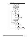
The step by step procedure for the CRC16 calculation is as follows:
1) Load a 16-bit register with FFFFh (all bits set to 1).
2) Execute the exclusive OR of the first character with the high order
byte in the register and place the result in the register.
3) Shift the register to the right by one bit.
4) If the bit that left the register on the right (flag) is a 1, execute the
exclusive OR of the polynomial 1010000000000001 with the
register.
5) Repeat steps 3 and 4 eight times.
6) Execute the exclusive OR of the next character with the high order
byte in the register and place the result in the register.
7) Repeat steps 3 to 6 for all the characters in the message.
8) The contents of the 16 bit register are the CRC code that is to be
added to the message.
8
2.4.1 CRC 16 Flow Chart
Hex FFFF
CRC 16
CRC 16 XOR byte
CRC 16
n=0
Shift to right CRC 16
NO
YES
Carry
CRC 16 XOR Hex A001
CRC 16
n=n+1
NO
YES
N>7
Next Byte
NO
End
message
YES
END
9
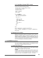
2.4.2 Visual Basic Calculate CRC16 example
Function CRC16(String As String) As String
Dim N As Integer, i As Integer, NByte As Integer
Dim CRC As Long, a As Byte
Dim Buffer As String
NByte = Len(String)
CRC = 65535
For i = 1 To NByte
a = Asc(Mid$(String, i, 1)) 'C(I)
CRC = (CRC Xor a) And &HFFFF
For N = 0 To 7
If CRC And 1 Then
CRC = (CRC \ 2)
CRC = (CRC Xor 40961)
Else
CRC = CRC \ 2
End If
Next
Next
Buffer = Right$("0000" + Hex$(CRC And &HFFFF), 4)
CRC16 = Chr$("&H" + Right$(Buffer, 2)) + Chr$("&H" + Left$(Buffer, 2))
End Function
2.5 Message Synchronisation
Message synchronisation between the transmitter and the receiver is
obtained by inserting a pause of at least 3.5 times the time of one
character between the messages. If the receiving device does not
receive for the time required for 3 characters, it considers the previous
message completed and concludes that the next byte received will be the
first of a new message and, consequently, an address.
3. The MODBUS Functions
This section provides a detailed description of the MODBUS functions
implemented on ATHENA CONTROLS instruments.
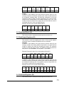
3.1 Read Output Status (01)
This function is used for requesting the ON or OFF status of binary
logical variables. Broadcast mode is not allowed.
Question
In addition to the address of the slave and the function code (01), the
message contains the starting address expressed in two bytes and the
number of bits to be read, also occupying two bytes. Address numbering
starts from zero (bit1 = 0) for MODBUS, or one (bit1 = 1) for JBUS.
10
Example: Request for slave 17 to read bits 0004 to 0015.
FUNC
DATA
start
Addr HI
DATA
start
Addr LO
DATA
bit #
HI
DATA
bit #
LO
CRC
ADDR
CRC
HI
LO
11
01
00
03
00
0C
CE
9F
Answer
In addition to the address of the slave and the function code (01), the
message comprises a character containing the number of data bytes and
the characters containing data. The data are compacted, so one byte
contains the status of 8 bits, the least significant bit of the first byte must
contain the bit corresponding to the starting address and so on. If the
number of bits to be read is not a multiple of 8, the last character must be
completed with zeros in the most significant bits.
Example: Answer to the request indicated above.
FUNC
DATA
Byte
Count
DATA
bit
04..11
DATA
bit
12..15
CRC
ADDR
CRC
HI
LO
11
01
02
CD
0B
6D
68
3.2 Read Input Status (02)
This function works in exactly the same way as the previous one.
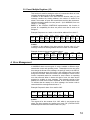
3.3 Read Output Registers (03)
This function is used for requesting the value of 16-bit (word) registers
containing numeric variables. Broadcast mode is not allowed.
Question
In addition to the address of the slave and the function code (03), the
message contains the starting address expressed in two bytes and the
number of words to be read, also occupying two bytes. The maximum
number of words that may be read is 125. Address numbering starts from
zero (word1 = 0) for MODBUS, or one (word1 = 1) for JBUS.
Example: Request for slave 25 to read registers 069 to 0071.
ADDR
FUNC
DATA
DATA
start
start
Addr HI Addr LO
DATA
word #
HI
DATA
word #
LO
CRC
CRC
HI
LO
19
03
00
44
00
03
46
06
Answer
In addition to the address of the slave and the function code (03), the
message comprises a character containing the number of data bytes and
the characters containing data. The registers require two bytes each, the
first of which contains the most significant byte.
Example: Answer to the request indicated above.
ADDR FUNC
19
03
DATA DATA DATA DATA DATA DATA DATA
Byte word word word word word word
Count 69 HI 69 LO 70 HI 70 LO 71 HI 71 LO
06
02
2B
00
00
00
64
CRC
CRC
HI
LO
AF
7A
3.4 Read Input Registers (04)
This function works in exactly the same way as the previous one.
11
3.5 Force Single Coil (05)
This function is used for forcing the status of a single binary variable ON
or OFF. Broadcast mode is allowed.
Question
In addition to the address of the slave and the function code (05), the
message contains the address of the variable to be forced in two bytes
and two characters of which the first is set to FFh (255) to force it ON and
00h to force it OFF, while the second is always set to zero. Address
numbering starts from zero (bit1 = 0) for MODBUS, from one (bit1 = 1) for
JBUS.
Example: Request to force bit 4 on slave 47 ON.
FUNC
DATA
bit #
HI
DATA
bit #
LO
DATA
ON/OFF
DATA
(zero)
CRC
ADDR
CRC
HI
LO
2F
05
00
03
FF
00
7A
74
Answer
The answer consists in retransmitting the message received once the
variable has been changed.
Example: Answer to request mentioned above.
FUNC
DATA
bit #
HI
DATA
bit #
LO
DATA
ON/OFF
DATA
(zero)
CRC
ADDR
CRC
HI
LO
2F
05
00
03
FF
00
7A
74
3.6 Preset Single Register (06)
This function is used for setting the value of a single 16-bit register.
Broadcast mode is allowed.
Question
In addition to the slave and the function code (06), the message contains
the address of the variable expressed in two bytes and the value to be
assigned. Address numbering starts from zero (word1 = 0) for MODBUS,
from one (word1 = 1) for JBUS.
Example: Request to force address 26 of slave 38 to 926.
FUNC
DATA
bit #
HI
DATA
bit #
LO
DATA
WORD
HI
DATA
WORD
LO
CRC
ADDR
CRC
HI
LO
26
06
00
19
03
9E
DF
82
Answer
The answer consists in retransmitting the message received once the
variable has been changed.
Example: Answer to request indicated above.
FUNC
DATA
bit #
HI
DATA
bit #
LO
DATA
WORD
HI
DATA
WORD
LO
CRC
ADDR
HI
LO
26
06
00
19
03
9E
DF
82
CRC
12
3.7 Read Status (07)
This function is used for reading the status of eight predetermined bits
with a compacted message. Broadcast mode is not allowed.
Question
The message consists only of the slave address and the function code
(07).
Example: Request of the status of slave 25.
ADDR
FUNC
CRC
HI
CRC
LO
19
07
4B
E2
Answer
In addition to the address of the slave and the function code (07), the
message comprises a character containing the status bits.
Example: Answer to the request indicated above.
FUNC
DATA
status
byte
CRC
ADDR
CRC
HI
LO
19
07
6D
63
DA
3.8 Force Multiple Coils (15)
This function is used for forcing the status of each binary variable in a
consecutive block. Broadcast mode is allowed.
Question
In addition to the address of the slave and the function code (15), the
message contains the starting address expressed in two bytes, the
number of bits to be written, the number of bytes containing the data and
the data characters. The data are compacted, so one byte contains the
status of 8 bits, the least significant bit of the first byte must contain the
bit corresponding to the starting address and so on. If the number of bits
to be written is not a multiple of 8, the last character must be completed
with zeros in the most significant bits. Address numbering starts from
zero (bit1 = 0) for MODBUS, from one (bit1 = 1) for JBUS.
Example: Request to force 4 bits starting from address 1 on slave 12. Bits
1 and 4 forced to "1" and the others to "0".
ADDR FUNC
0C
DATA
DATA
start
start
Addr HI Addr LO
0F
00
DATA
bit #
HI
DATA
bit #
LO
DATA
Byte
Count
DATA
bit
1..4
CRC
HI
LO
00
04
01
09
3F
09
00
CRC
Answer
In addition to the address of the slave and the function code (15), the
message contains the starting address and the number of bits written.
Example: Answer to request indicated above.
ADDR
FUNC
0C
0F
DATA
DATA
start
start
Addr HI Addr LO
00
00
DATA
bit #
HI
DATA
bit #
LO
CRC
HI
LO
00
04
55
15
CRC
13
3.9 Preset Multiple Registers (16)
This function is used for setting the value of a consecutive block of 16-bit
registers. Broadcast mode is allowed. Question.
In addition to the address of the slave and the function code (16), the
message contains the starting address, the number of words to be
written, the number of bytes that contain data and the data characters.
Address numbering starts from zero (word1 = 0) for MODBUS, from one
(word1 = 1) for JBUS.
NOTE: In the ATHENA CONTROLS implementation, this function is
present for compatibility but does not permit more than 8 word to be
assigned.
Example: Request to set 1 word to value 268 at address 35 on slave 17.
ADDR FUNC
11
DATA
DATA
start
start
Addr HI Addr LO
10
00
DATA
word #
HI
DATA
word #
LO
DATA
Byte
Count
DATA
word
35 HI
DATA
word
35 LO
CRC
HI
LO
00
01
02
01
0C
6C
87
22
CRC
Answer
In addition to the address of the slave and the function code (16), the
message contains the starting address and the number of words written.
Example: Answer to the request indicated above.
FUNC
DATA
start
Addr HI
DATA
start
Addr LO
DATA
word #
HI
DATA
word #
LO
CRC
ADDR
CRC
HI
LO
11
10
00
22
00
01
A3
53
4. Error Management
In MODBUS there are two types of errors, handled in different ways:
transmission errors and operating errors. Transmission errors are errors
that change the format of the message, the parity (if used) or the CRC16.
A device that detects errors of this type in the message treats it as invalid
and gives no answer. When the format of the message is correct but the
function requested cannot be executed for some reason, an operating
error has occurred. When it detects this kind of error, the slave device
answers by sending an error message. This message consists of the
address, the code of the function requested, an error code and the CRC.
To indicate that the answer is an error message, the function code is
returned with the most significant bit set to "1".
Example: Request for slave 10 to read bit 1185.
ADDR
FUNC
0A
01
DATA
DATA
start
start
Addr HI Addr LO
04
A1
DATA
bit #
HI
DATA
bit #
LO
CRC
CRC
HI
LO
00
01
AC
63
Answer
The request is for the contents of bit 1185, which is not present on the
slave. The slave answers by sending error code "02" (ILLEGAL DATA
ADDRESS) and returns the function code 81h (129).
14
Example: Error code in response to the request indicated above.
ADDR
0A
FUNC
81
DATA
Except.
Code
CRC
CRC
HI
LO
02
B0
53
4.1 Error Codes
Although the MODBUS standard uses 8 error codes, the ATHENA
CONTROLS implementation of the protocol uses only four:
Code
01
Name
ILLEGAL FUNCTION
02
ILLEGAL DATA
ADDRESS
ILLEGAL DATA VALUE
03
07
NAK - NEGATIVE
ACKNOWLEDGMENT
Meaning
The function code received does not correspond
to a function allowed on the addressed slave.
The address to which the data field refers is not
an address allowed on the addressed slave.
The value to be assigned, specified in the data
field, is not allowed for this address.
The function cannot be performed under the
current operating conditions or an attempt has
been made to write in a read-only address.
5. MODBUS ON ATHENA CONTROLS PLATINUM® INSTRUMENTS
5.1 Serial communications parameters
The parameters are shown in the below table:
Parameter
Communications protocol
Serial address
Baud rate
Parameter
code
Prot
Addr
baudr
Set up range
MbuS / JbuS
1 ... 247
1200, 2400, 4800, 9600, 19200
The protocol is chosen by means the M.buS o JbuS selection.
The address can be set among 1..247 and must be unique for each
instrument connected on the same line.
The Baud rate parameter enable a clear and simple communications
speed setting.
No Parity and stop bit must be set. They have already been set by the
manufacturer as follows:
Parity
= none
Stop bit = 1
5.2 Communications time
The messages, as described in Chapter 2.4, must be exchanged with an
internal pause that is less than 3 times the time required for a character
to be exchanged, otherwise it would be interpreted as the end of the
message. The ATHENA CONTROLS instruments with the MODBUS
protocol are able to receive and transmit characters without an interval.
Between a master message and the following reply on the part of the
instrument there is a latent time lapse necessary for the completion of the
function. This is connected to the fact that, once a command has been
received, the instrument responds only after having completed the
15
requested function. To evaluate the lapse in time for different functions
reference can be made to the following expressions:
TL ≅ 3Tc + Ts
Request:
where:
TL = Elapsed time.
TC = Time of a character.
TS = Variable time from 0 to 10mS which is dependent on the internal
processes.
TL ≅ 3Tc + Ts + Tw
Assignment:
where:
TL = Elapsed time.
TC = Time of a character.
TS = Variable time from 0 to 10mS which is dependent on the internal
processes.
TW = Multiple time of 25mS which is dependent on the number of bytes
to be written. For assignment of words, this time can be 0, 25 or 50 ms
depending on whether both one or none of the two bytes is equal to
the preceding value; for the assignment of bit Tw, it can be a value from
0 to 100mS.
5.3 Data Base
The ATHENA CONTROLS instrument variables available for serial
communication through the MODBUS protocol are contained in two
distinct sections: the bit zone and the word zone.
5.4 Bit Zone
The bit zone is made up of 16 addressable bits that contain information
on the functioning status of the instruments. With some instruments,
certain bits are not used; the status request for these bits with the 01 and
02 functions is permitted but returns a fixed value of 0; these bits are
indicated in the tables by the presence of a hyphen "-". The assignment
of the bit status with the 05 and 15 functions is only allowed on
addresses in which this is possible, which condition is indicated by "R/W".
5.5 Word Zone
The word zone is made up of 128 addressable words that contain control
variables and the instrument parameters. With some instruments certain
words are not used; the request for the values of these words with the 03
and 04 functions is permitted but returns a fixed value of 0; these words
are indicated in the table by the presence of a hyphen "-". The
assignment of the word value with the 06 and 16 functions is only allowed
on addresses in which this is possible, which condition is indicated by
"R/W". The variables and parameters are coded as integer numbers with
a plus or minus sign (two's complement) without taking into account the
decimal point in the representation (for example: the Proportional Band
displayed on the screen with a decimal digit "25.0" is transmitted as 250).
Assignment is only allowed within the values assigned to each
parameter, any attempt to assign a value outside of those permitted
within the field, will cause the instrument to respond with an error
message and a an exception code equal to 3, and the assignment will not
be carried out.
16
5.6 Assignment of the parameters and E2PROM
All the parameters modified from keyboard or assigned through serial
communication, come written in a permanent way in the EEPROM of the
instruments. Like known good, these components have limited writing
cycles beyond to which the component could be damaged. In our case
the number of cycles of writing are about 10.000 and also if this number
could appear limited, we must be held present that the writings during the
arc of life of the instrument don't arrive to overcome the thousand of
cycles. Different thing is when we talk about the serial communication. In
fact the computer could assign any parameter and with any frequency to
the regulators.
Being well aware of this fact, Athena Controls has provided to protect the
component in matter according to different hardware formality and
resources of the instruments. One of the protection made consists of the
fact to compare the new given with the datum already resident. If the two
data correspond, no writing doesn't happen in as not necessary and the
new given comes writing only and entirely if the two data disagree
between them.
Normally the datum that has a frequency of better writing it is the value of
Setpoint. In the instruments C10, M10 and M300 in as not furnished of
NOVRAM or buffered RAM, exists two formality of assignment of the
Setpoint that is:
1) Assignment to the Jbus address 2
2) Assignment to the Jbus address 5
With the first formality, the Setpoint could be assigned endless times
because it work in the RAM of the microprocessor but attention because
at the turning off of the regulator this datum comes lost for engage the
last value that had stayed written locally from keyboard or from the serial
to the Jbus address 5.
With the second formality the datum comes written in a permanent way
directly in the EEPROM of the instrument and the writing must be limited
to a real necessity.
The instruments of the series M5000, X100, X400, X5000 and X7000
possessing a different hardware structure, furnished that is of NOVRAM
or buffered RAM, they are not subdued to the limits previously exposed
and the assignments of the Setpoint to the Jbus addresses 2 or 5 don't
involve any difference. The two addresses come maintained active only
for a problem of compatibility with the preceding series.
6. Electrical Connections
6.1 General Description
All the Platinum® controllers may be fitted with a two wire (half duplex)
RS485 serial comm.s option. It makes the wiring simpler and enables a
larger connection length (maximum 1200 m).
The Platinum ® C10, M10, M300 and M400 instruments do not have any
line termination or polarisation system. If necessary a termination
resistance (120Ω ¼ W) must be connected to the terminals of the last
instrument of the line. In any case the polarisation is not possible.
The Platinum ® M5000, X100, X400 and X5000 instruments do have any
line termination or polarisation system. Please refere to the specific
chapter on these instruments.
17
6.2 Communication Cable Laying Recommendations
In order to minimise interference caused by the external environment to
serial communication, and thus obtain maximum efficiency between the
supervisor and the instruments, a few essential technical precautions
must be taken.
The most important and easiest to implement of all is to separate the
power or power supply lines from the communication lines and lay them
as far as possible from remote-controlled switches, electromagnets,
powerful motors, etc. The same rule applies to the control panel in that it
is pointless to cable the control panel perfectly and then haphazardly
"throw" the cables into the channel or vice versa. If the communication
cables are extended to another control panel or other equipment, leave a
space in the terminal board, isolated from all the other cables (normally
towards the sides).
The type of cable used is of fundamental importance for the functioning of
the entire system. The most important condition to be respected is the
cable's capacity per meter (pF/m). The lower the capacity of the cable is
the longer the line can be. Consequently, power cables, shielded coaxial
cables and general channel cables are to be avoided under all
circumstances in that they have an extremely high capacity per metre. In
addition, to ensure high interference rejection, the cables must be twisted
and preferably provided with a metal shield to be connected to an
efficient ground socket (on one side only).
Two examples of cables with suitable characteristics produced by Belden
are indicated below:
A) Belden code 9729 Z = 100 Ω
pF/m = 41
B) Belden code 9502 Z = 150 Ω
pF/m = 98
6.3 Instruments with an RS-485 interface (2 wire)
The line requires twisted cable with a characteristic impedance of about
120 Ω.
Normally this type of connection uses a standard 4-wire communication
interface. The transmission and reception signals for the computer and
the communicating device (Tx+Rx+ and Tx-Rx-) can be paralleled,
resulting in a single duplex connection RTx+ and RTx-.
The communication port cannot usually work if it is connected in this way
as every time the supervisor is transmitting a message, it is also present
on the receiving port before awaiting the reply from the other devices. To
prevent this problem occurring, the supervisor uses the RTS (Request To
Send) signal from the communication port. Before beginning a
transmission, the supervisor “raises” the status of its RTS signal to inhibit
its receiver. When the transmission has ended, the supervisor brings the
RTS signal back to “zero” to re-enable its receiver. In the same way, the
devices connected to the supervisor must be able to manage the
direction of the message that is flowing, otherwise the communication will
fail. ATHENA CONTROLS controllers include this ability in their software.
There are commercially available interfaces for handling the RTS signal
at the hardware level, so that it is completely transparent and not
required by the communications software.
It is strongly recommended that the two ends of the link between the
various devices is correctly terminated, as shown in the following drawing
to demonstrate the principle.
18
Rt
Device 1
Supervisor
Device 2
Device "n"
Rt
Common
Rg
Rg
G/R
G/R
Rg
G/R
Rg
G/R
G
R
G/R
Rt
= Transmitter
= Receiver
= Bi-directional (Receiver/Transmitter) buffer
= Termination resistance: the transmitter can drives up to 32
receivers plus two 120 Ω resistors.
Rg = 100 Ω Resistor
From the above drawing it may be seen that a “star” connection is not
valid. Each branch would have to be terminated, which in turn would
reduce the overall the impedance of the line. In these conditions, the
signal level would be too low for reliable communications.
6.3.1 References
GOULD
APRIL
GLOBAL ENG. DOC.
Gould Modbus Protocol Reference Guide
(PI-MBUS-300 Rev. B)
JbuS Specification
EIA STANDARD RS -485
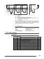
7. C10 / M10 Controllers
7.1 Bit Zone
Address
Modbus
JbuS
0
1
2
3
4
5
6
7
8
9
10
11
12
13
14
15
1
2
3
4
5
6
7
8
9
10
11
12
13
14
15
16
Variable
Main output condition (0 = OFF, 1 = ON)
AL2 alarm status (0 = OFF, 1 = ON)
AL3 alarm status (0 = OFF, 1 = ON)
Out of range (0 = Normal operation, 1 = Safety)
Auto-Tune (0 = OFF, 1 = Run)
Out of range (0 = Normal operation, 1 = Safety)
-
Type
R
R
R
R
R
R
-
19
7.2 Read Status
Function 07 (Read Status) returns an eight bit status with the following
meanings:
Bit
Address
1 (LSB)
2
3
4
5
6
7
8 (MSB)
1
2
3
4
5
6
7
8
Variable
Main output condition (0 = OFF, 1 = ON)
AL2 alarm status (0 = OFF, 1 = ON)
AL3 alarm status (0 = OFF, 1 = ON)
Out of range (0 = Normal operation, 1 = Safety)
Auto-Tune (0 = OFF, 1 = Run)
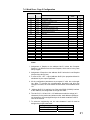
7.3 Word Zone - Page 1 Parameters
Address
Modbus
JbuS
Variable
0
1
2
3
4
5
1
2
3
4
5
6
Process variable
Setpoint
Main output
Target Setpoint
Local Setpoint
3
Proportional Band (Hysteresis ON - OFF)
6
7
Overshoot control
7
8
Integral time
8
9
Derivative time
9
10
Output cycling time
10
11
Low range
11
12
High range
12
13
AL2 Alarm threshold
13
14
AL3 Alarm threshold
14
15
AL2 Alarm Hysteresis
15
16
16 .. 28
29
17 .. 29
30
AL3 Alarm Hysteresis
Setpoint low limit
30
31
Setpoint high limit
31
32
32
33
Main output high limit
33
34
34
35
Setpoint ramp up
35
36
Setpoint ramp down
36
37
Input filter
37
38
Input shift
38
39
Auto-Tune enable
39
40
40
41
Serial comm.s address
41
42
42
43
Retransmission low range
43
44
44 .. 99
45 .. 100
Retransmission high range
-
Parameter
Code
P.b. (hy))
O.C.
t.i.
t.d.
t.c.
Sc.Lo
Sc.Hi
A2S.P
A3S.P
A2hy
A3hy
-
S.P. L
S.P. H
-
OP. H
-
Sl. u
Sl. d
t.FiL
In.Sh
tune
-
Addr
-
rt.Lo
rt.Hi
-
Type
R
1
R/W
R
R
2
R/W
R/W
R/W
R/W
R/W
R/W
R
R
R/W
R/W
R/W
R/W
R/W
R/W
R/W
R/W
R/W
R/W
R/W
R/W
R/W
R/W
R/W
-
20
7.4 Word Zone - Page 2 Configuration
Address
Modbus
JbuS
Variable
100
101
101
102
Configuration code
102
103
AL3 alarm configuration code
103
104
Engineering units
104
105
Decimal point
105
106
Low range for engineering units
106
107
High range for engineering units
107
108
Communications protocol
108
109
Baud rate
109
110
Retransmitted range
110
111
112
111
112
113
Password
113
114
RTX low range calibration value (Reserved)
114
115
RTX high range calibration value (Reserved)
115..119
120
121
122
123
124
125
126
127
116..120
121
122
123
124
125
126
127
128
Parameter
Code
Type
-
4
R/W
ConF
Con.2
unit
Sc.d.d
Sc.Lo
Sc.Hi
Prot
baud
retr
R/W
R/W
4
R/W
4
R/W
4
R/W
8
R/W
9
R/W
10
R/W
Code
CAL.3
CAL.4
-
-
4/7
R/W
-
Factory code
Product code (“C1”)
Software release
Custom code
-
4
R/W
R/W
5
R(W)
6
R
R
6
R
R
R
-
Notes:
1. Assignment of Setpoint to the address JbuS 2 writes the Computer
Setpoint. It is different from the Local Setpoint, which can be in any case
set by keypad.
2. Assignment of Setpoint to the address JbuS 5 writes the Local Setpoint
(the previous value is lost).
3. In case of ON - OFF output (address JbuS 6) the proportional band is
substituted by the output Hysteresis.
4. All the configuration parameters are accepted, if valid, but not brought
into effect. To execute the reconfiguration procedure and bring the
changes into effect, the code 55AAh must be written at the address JbuS
121.
5. Address JbuS 121 is read only, but if the code 55AAh (21930d) is written
at this address, the configuration is brought into effect.
6. The JbuS 122 + 123 and 124 + 125 addresses contain the strings (of 4
characters) for the product and release codes: each address represents
two characters, the most significant byte in the word contains the ASCII
code of the second.
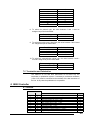
7. To select the engineering unit, the value between 0 and 10 must be
assigned as per the below table:
Engineering unit
°C
°F
Serial value
0
1
21
2
3
4
5
6
7
8
9
10
none
nU
U
nA
A
bar
PSI
rh
Ph
8. To select the protocol type, the value between 0 and 1 must be
assigned as per the below table:
Protocol type
Modbus
JbuS
Serial value
0
1
9. To select the serial comm.s baud rate, the value between 0 and 3 must
be assigned as per the below table:
Baud Rate
1200
2400
4800
9600
Serial value
0
1
2
3
10. To select the retransmission signal type, the value between 0 and 1
must be assigned as per the below table:
Retransm. signal type
0 .. 20 mA
4 .. 20 mA
Serial value
0
1
7.5 Termination and Polarisation
The Platinum ® C10 and M10 instruments do not have any line
termination or polarisation system. If necessary a termination resistance
(120Ω ¼ W) must be connected to the terminals of the last instrument of
the line. In any case the polarisation is not possible.
8. M300 Controller
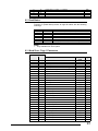
8.1 Bit zone
Address
Modbus
JbuS
0
1
2
3
4
5
6
7
8
9
10
1
2
3
4
5
6
7
8
9
10
11
Variable
1
Timer function status (0 = OFF, 1 = Run)
Main output condition (0 = OFF, 1 = ON)
Alarm condition AL2 (0 = OFF, 1 = ON)
Alarm condition AL3 (0 = OFF, 1 = ON)
Out of range (0 = Normal operation, 1 = Safety)
Auto-Tune (0 = OFF, 1 = Run)
Out of range (0 = Normal operation, 1 = Safety)
Keypad lock (0 = locked, 1 = unlocked)
Type
R/W
R
R
R
R
R
R
R/W
22
11
12
13
14
15
12
13
14
15
16
Outputs lock (0 = locked, 1 = unlocked)
-
R/W
-
8.2 Read Status
Function 07 (Read Status) returns an eight bit status with the following
meanings:
Bit
Address
1 (LSB)
2
3
4
5
6
7
8 (MSB)
1
2
3
4
5
6
7
8
Variable
1
Timer function status (0 = OFF, 1 = Run)
Main output condition (0 = OFF, 1 = ON)
Alarm condition AL2 (0 = OFF, 1 = ON)
Alarm condition AL3 (0 = OFF, 1 = ON)
Out of range (0 = Normal operation, 1 = Safety)
Auto-Tune (0 = OFF, 1 = Run)
Notes:
1. Only available with Timer option.
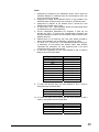
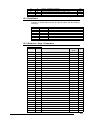
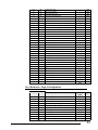
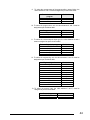
8.3 Word Zone - Page 1 Parameters
Address
Modbus
JbuS
Variable
0
1
2
3
4
5
1
2
3
4
5
6
Process variable
Setpoint
Main output
Target Setpoint
Local Setpoint
4
Proportional Band (Hysteresis ON - OFF)
6
7
Overshoot control
7
8
Integral time
8
9
Derivative time
9
10
Cycle time
10
11
Low range
11
12
High range
12
13
AL2 Alarm threshold
13
14
AL3 Alarm threshold
14
15
AL2 Alarm Hysteresis
15
16
AL3 Alarm Hysteresis
16
17
Heat/cool proportional band
17
18
Heat/cool integral time
18
19
Heat/cool derivative time
19
20
Heat/cool dead band
20
21
Cool output cycling time
21
22
Cool output high limit
22
23
Motor travel time
23
24
Minimum output step
24
25
Timer setting
25
26
Stand-by Setpoint
26
27
Stand-by Setpoint of Timer
27
28
Soft-start output value
28
29
-
Parameter
Code
P.b. (hy.)
O.C.
t.i.
t.d.
t.c.
Sc.Lo
Sc.Hi
A2S.P
A3S.P
A2hy
A2hy
P.b. C
t.i. C
t.d. C
d.bnd
t.c. C
OP.HC
MU.tM
MU.Hy
tiMe
S.P 2
tM.S.P
St.OP
-
Type
R
1
R/W
2
R
1
R/W
3
R/W
R/W
R/W
R/W
R/W
R/W
R
R
R/W
R/W
R/W
R/W
R/W
R/W
R/W
R/W
R/W
R/W
R/W
R/W
R/W
R/W
R/W
R/W
-
23
29
30
Setpoint low limit
30
31
Setpoint high limit
31
32
Error dead band
32
33
Main output high limit
33
34
Output safety value
34
35
Setpoint ramp up
35
36
Setpoint ramp down
36
37
Input filter
37
38
Input shift
38
39
Auto-Tune enable
39
40
40
41
Serial comm.s address
41
42
42
43
Retransmission low range
43
44
Retransmission high range
44
45
start-up Setpoint
45
46
Start Up Holding time
46
47
start-up output high limit
47
48
Timer remaining time
48
49
Load current (CT option)
49 .. 99
50 .. 100
S.P. L
S.P. H
d.Err
OP. H
Sa.OP
Sl. u
Sl. d
t.FiL
In.Sh
tune
R/W
-
R/W
Addr
-
rt.Lo
rt.Hi
S.P.S.U
t.h.S.U
OP.HS
tM.r.
t.Cur
-
-
R/W
R/W
R/W
R/W
R/W
R/W
R/W
R/W
R/W
R/W
R/W
R/W
R/W
R/W
R/W
R
-
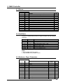
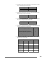
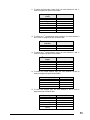
8.4 Word Zone - Page 2 Configuration
Address
Modbus
JbuS
Variable
100
101
101
102
Configuration code
102
103
AL3 alarm configuration code
103
104
Engineering units
104
105
Decimal point
105
106
Low range for engineering units
106
107
High range for engineering units
107
108
Communication protocol
108
109
Baud rate
109
110
Retransmission range
110
111
Retransmission signal selection
111
112
Current transformer range
112
113
Password
113
114
RTX low range calibration value (Reserved)
114
115
RTX high range calibration value (Reserved)
115
116
Timer/Start-up operating mode
116
117
Timer action
117..119
120
121
122
123
124
125
126
127
118..120
121
122
123
124
125
126
127
128
Param. Code
Type
-
5
R/W
ConF
Con.2
unit
Sc.d.d
Sc.Lo
Sc.Hi
Prot
baud
retr
rtH
Ht.F.S
Code
CAL.3
CAL.4
t.Mod
t.Act
-
Factory code
Product code ( “M3”)
Software release
Custom code
-
-
R/W
R/W
5
5/8
R/W
5
R/W
5
R/W
5
R/W
9
R/W
10
R/W
11
R/W
12
R/W
R/W
R/W
R/W
R/W
13
R/W
14
6
R(W)
7
R
7
R
R
-
24
Notes:
1. Assignment of Setpoint to the addresses JbuS 2 and 4 writes the
Computer Setpoint. It is different from the Local Setpoint, which can
be in any case set by keypad.
2. Assignment of output at the address JbuS 3 is only possible if the
Auto/Man option if fitted and when the controller is in Manual mode.
3. Assignment of Setpoint to the address JbuS 5 writes the Local
Setpoint (the previous value is lost).
4. In case of ON - OFF output (address JbuS 6) the proportional band
is substituted by the output Hysteresis.
5. All the configuration parameters are accepted, if valid, but not
brought into effect. To execute the reconfiguration procedure and
bring the changes into effect, the code 55AAh must be written at the
address JbuS 121.
6. Address JbuS 121 is read only, but if the code 55AAh (21930d) is
written at this address, the configuration is brought into effect.
7. The JbuS 122 + 123 and 124 + 125 addresses contain the strings (of
4 characters) for the product and release codes: each address
represents two characters, the most significant byte in the word
contains the ASCII code of the second.
8. To select the engineering unit, the value between 0 and 10 must be
assigned as per the below table:
Engineering unit
°C
°F
none
nU
U
nA
A
bar
PSI
rh
Ph
Serial value
0
1
2
3
4
5
6
7
8
9
10
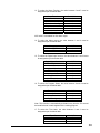
9. To select the protocol type, the value between 0 and 1 must be
assigned as per the below table:
Protocol type
Modbus
JbuS
Serial value
0
1
10. To select the serial comm.s baud rate, the value between 0 and 3
must be assigned as per the below table:
Baud Rate
1200
2400
4800
9600
Serial value
0
1
2
3
25
11. To select the retransm. output range, the value between 0 and 1
must be assigned as per the below table:
Variable
0 .. 20 mA
4 .. 20 mA
Serial value
0
1
12. To select the retransmitted variable (PV or SP), a value between 0
and 1 must be assigned as per the below table:
Variable
PV
SP
Serial value
0
1
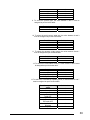
13. To select the Timer/Start-up operating mode, a value between 0 and
7 must be assigned as per the below table:
Timer/Start-up operating mode
Disabled
Start-up
Counting inside band
Counting inside band / End mode OFF
Counting when launched
Counting when launched / End mode OFF
Counting disable when launched
Stand-by Setpoint
Serial
value
0
1
2
3
4
5
6
7
14. To select the Timer action, a value between 0 and 7 must be
assigned as per the below table:
Launch
By Keypad
By Keypad
Key +
at power on
Key +
at power on
By Keypad
By Keypad
Key +
at power on
Key +
at power on
Timer action
OP3 status
OFF
ON
OFF
Serial value
Time
Second
Second
Second
0
1
2
ON
Second
3
OFF
ON
OFF
Minute
Minute
Minute
4
5
6
ON
Minute
7
8.5 Termination and Polarisation
The Platinum ® M300 instruments do not have any line termination or
polarisation system. If necessary a termination resistance (120Ω ¼ W)
must be connected to the terminals of the last instrument of the line.
In any case the polarisation is not possible.
26
9. M400 Controller
9.1 Bit zone
Address
Modbus
JbuS
0
1
2
3
4
5
6
7
8
9
10
11
12
13
14
15
1
2
3
4
5
6
7
8
9
10
11
12
13
14
15
16
Variable
Type
1
Timer function status (0 = OFF, 1 = Run)
2
Auto/Man (0 = Auto, 1 = Man)
Control output status (0 = OFF, 1 = ON)
AL2 alarm status ( 0 = OFF, 1 = ON )
AL3 alarm status ( 0 = OFF, 1 = ON )
Out of range (0 = Normal operation, 1 = Safety)
Auto Tuning ( 0=OFF 1=Run )
Out of range (0 = Normal operation, 1 = Safety)
Keypad lock (0 = locked, 1 = unlocked)
Outputs lock (0 = locked, 1 = unlocked)
Logic input #1 ( 0=Open 1=Close )
-
R/W
R/W
R
R
R
R
R
R
R/W
R/W
R
-
9.2 Read Status
Function 07 (Read Status) returns an eight bit status with the following
meanings:
Bit
Address
1 (LSB)
2
3
4
5
6
7
8 (MSB)
1
2
3
4
5
6
7
8
Variable
1
Timer function status (0 = OFF, 1 = Run)
2
Auto/Man (0 = Auto, 1 = Man)
Control output status (0 = OFF, 1 = ON)
Alarm 2 ( 0 = OFF, 1 = ON )
Alarm 3 ( 0 = OFF, 1 = ON )
Out of range (0 = Normal operation, 1 = Safety)
Auto Tune ( 0=Disabled 1=Run )
Notes:
1. Only available with Timer option.
2. Only available with Auto/Man function.
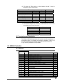
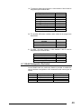
9.3 Word zone - Page 1 Parameters
Address
Modbus
JbuS
Variable
0
1
2
3
4
5
1
2
3
4
5
6
Process variable
Setpoint
Main output
Local Setpoint
Local Setpoint
4
Proportional Band (Hysteresis ON - OFF)
6
7
Overshoot Control
7
8
Integral time
8
9
Derivative time
9
10
Cycle time
10
11
Low range
11
12
High range
Parameter
Code
Type
-
R
1
R/W
2
R(W)
1
R/W
3
R/W
R/W
P.b. (hy.)
O.C.
t.i.
t.d.
t.c.
Sc.Lo
Sc.Hi
R/W
R/W
R/W
R/W
R
R
27
12
13
AL2 alarm threshold
13
14
AL3 alarm threshold
14
15
AL2 alarm Hysteresis
15
16
AL3 alarm Hysteresis
16
17
Relative Cold Gain
17
18
Cool output Hysteresis (On-OFF only)
18
19
-
19
20
Heat/Cool dead band
20
21
Cool output cycling time
21
22
Cool output maximum value
22
23
Motor travel time
23
24
Minimum output step
24
25
Timer setting
25
26
Stand-by Setpoint
26
27
Soft start output high limit
27
28
Soft-start activation time
28
29
29
30
Setpoint low limit
30
31
Setpoint high limit
31
32
PID Dead Band
32
33
Main output high limit
33
34
Output safety value
34
35
Setpoint ramp up
35
36
Setpoint ramp down
36
37
Input filter
37
38
Input shift
38
39
Start/Stop One shoot tuning ( 0=Stop 1=Run)
39
40
-
40
41
Serial comm.s address
41
42
-
42
43
Retransmission low range
43
44
Retransmission high range
44
45
Start-Up Setpoint
45
46
Start-Up Hold time
46
47
Output high milit during Start-up
47
48
Timer remaining time
48
49
49 - 99
50 - 100
Load current in ampere
-
A2S.P
A3S.P
A2hy
A2hy
r.C.Ga
Hy. C
d.bnd
t.c. C
OP.HC
MU.tM
MU.Hy
tiMe
tM.S.P
St.OP
St.tM
R/W
-
R/W
S.P. L
S.P. H
d.Err
OP. H
Sa.OP
Sl. u
Sl. d
t.FiL
In.Sh
tune
Addr
rt.Lo
rt.Hi
S.P.S.U
t.h.S.U
OP.HS
tM.r.
t.Cur
R/W
R/W
R/W
R/W
R/W
R/W
R/W
R/W
R/W
R/W
R/W
R/W
R/W
R/W
R/W
R/W
R/W
R/W
R/W
R/W
R/W
R/W
R/W
R/W
R/W
R/W
R/W
R/W
R/W
R/W
R
-
-
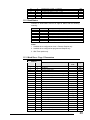
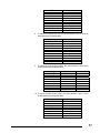
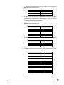
9.4 Word zone - Page 2 Configuration
Address
Modbus
JbuS
Variable
100
101
-
101
102
Configuration code
102
103
AL3 alarm configuration code
103
104
Engineering units
104
105
Decimal point
105
106
Low range for engineering units
106
107
High range for engineering units
Parameter
Code
ConF
Con.2
unit
Sc.d.d
Sc.Lo
Sc.Hi
Type
R/W
5
R/W
5
R/W
5/8
R/W
5
R/W
5
R/W
5
28
107
108
Communications protocol
108
109
Baud rate
109
110
Retransmission range
110
111
Retransmission signal selection
111
112
Current transformer range
112
113
Password
113
114
RTX low range calibration value (Reserved)
114
115
RTX high range calibration value (Reserved)
115
116
Timer operating mode
116
117
Timer action
117
118
Digital input function
118
119
-
119
120
-
120
121
Factory code
Prot
baud
retr
rtH
Ht.F.S
Code
CAL.3
CAL.4
t.Mod
t.Act
IL.Fn
-
R/W
9
R/W
10
R/W
11
R/W
12
R/W
R/W
R/W
R/W
R/W
13
R/W
14
R/W
15
R(W)
7
121
122
Product code (“M4”)
122
123
-
123
124
Software release (p. es. “ 00A”)
124
125
-
125
126
Custom code
126
127
-
127
128
-
6
R
R
7
R
-
R
-
-
Notes:
1. Assignment of Setpoint to the addresses JbuS 2 and 4 writes the
Computer Setpoint. It is different from the Local Setpoint, which can
be in any case set by keypad.
2. Assignment of output at the address JbuS 3 is only possible if the
the Auto/Man option if fitted and when the controller is in Manual
mode.
3. Assignment of Setpoint to the address JbuS 5 writes the Local
Setpoint (the previous value is lost).
4. In case of ON - OFF output (address JbuS 6) the proportional band
is substituted by the output hysteresis.
5. All the configuration parameters are accepted, if valid, but not
brought into effect. To execute the reconfiguration procedure and
bring the changes into effect, the code 55AAh must be written at the
address JbuS 121.
6. Address JbuS 121 is read only, but if the code 55AAh (21930d) is
written at this address, the configuration is brought into effect.
7. The JbuS 122 + 123 and 124 + 125 addresses contain the strings
(of 4 characters) for the product and release codes: each address
represents two characters, the most significant byte in the word
contains the ASCII code of the second.
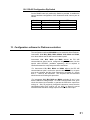
8. To select the engineering unit, the value between 0 and 10 must be
assigned as per the below table:
Engineering unit
°C
°F
none
nU
U
nA
Serial value
0
1
2
3
4
5
29
A
bar
PSI
rh
Ph
6
7
8
9
10
9. To select the protocol type, the value between 0 and 1 must be
assigned as per the below table:
Protocol type
Modbus
JbuS
Serial value
0
1
10. To select the serial comm.s baud rate, the value between 0 and 3
must be assigned as per the below table:
Baud Rate
1200
2400
4800
9600
Serial value
0
1
2
3
11. To select the retransm. output range, the value between 0 and 1
must be assigned as per the below table:
Variable
0 .. 20 mA
4 .. 20 mA
Serial value
0
1
12. To select the retransmitted variable, a value between 0 and 3 must
be assigned as per the below table:
Variable
PV
SP
MV ( OP Heat )
MVC ( OP Cool )
Serial value
0
1
2
3
13. To select the Timer/Start-up operating mode, a value between 0 and 7
must be assigned as per the below table:
Timer/Start-up operating
mode
Disabled
Start-up
Counting inside band
Counting inside band / End
mode OFF
Counting when launched
Counting when launched /
End mode OFF
Counting disable when
launched
Stand-by Setpoint
Serial value
0
1
2
3
4
5
6
7
30
14. To select the Timer action, a value between 0 and 7 must be
assigned as per the below table:
Timer action
Launch
OP3 status
By Keypad
OFF
By Keypad
ON
Key + at power on
OFF
Key + at power on
ON
By Keypad
OFF
By Keypad
ON
Key + at power on
OFF
Key + at power on
ON
Serial value
Time
Second
Second
Second
Second
Minute
Minute
Minute
Minute
0
1
2
3
4
5
6
7
15. To select the digital input functions, a value between 0 and 4 must
be assigned as per the below table:
Digital input function
None
Keypad lock
Manual mode
Stand-by Setpoint
Timer launch
Serial value
0
1
2
3
4
9.5 Termination and Polarization
The Platinum ® M400 instruments do not have any line termination or
polarization system. If necessary a termination resistance (120Ω ¼ W)
must be connected to the terminals of the last instrument of the line.
In any case the polarization is not possible.
10. M5000 Controller
10.1 Bit zone
Address
Modbus
JbuS
0
1
2
3
4
5
6
7
8
9
10
11
12
13
14
15
16
17
18
19
20
21
1
2
3
4
5
6
7
8
9
10
11
12
13
14
15
16
17
18
19
20
21
22
Variable
Remote status (0=LOC, 1=REM)
Auto/Man ( 0 = Auto 1 = Man )
AL3 alarm status ( 0 = OFF, 1 = ON )
AL4 alarm status ( 0 = OFF, 1 = ON )
AL1 alarm status ( 0 = OFF, 1 = ON )
AL2 alarm status ( 0 = OFF, 1 = ON )
Out of range (0 = Normal operation, 1 = Safety)
Self Tuning ( 0=Disabled 1=Run )
Out of range (0 = Normal operation, 1 = Safety)
st
1 Stored setpoint
nd
2 Stored setpoint
IL1 Digital input status (0 = OFF, 1 = ON)
IL2 Digital input status (0 = OFF, 1 = ON)
Keys enable ( 0=Enabled 1=Disabled )
Slope enable ( 0=Disabled 1=Enabled )
Type
R/W
R/W
R
R
R
R
R
R
R
R
R/W
R/W
R
R
R/W
R/W
31
22
23
24
25
26
23
24
25
26
27
Hold PV ( 0=Disabled 1=Enabled )
OP1 forced status by serial comm.s ( 0 = OFF 1 = On )
OP2 forced status by serial comm.s ( 0 = OFF 1 = On )
OP3 forced status by serial comm.s ( 0 = OFF 1 = On )
OP4 (logic) forced status by serial comm.s ( 0 = OFF 1 = On )
R/W
19
R/W
19
R/W
19
R/W
19
R/W
10.2 Read Status
Function 07 (Read Status) returns an eight bit status with the following
meanings:
Bit
Address
1 (LSB)
2
3
4
5
6
7
8 (MSB)
1
2
3
4
5
6
7
8
Variable
Local setpoint/Remote ( 0 = Local 1 = Remote )
Auto/Man ( 0 = Auto 1 = Man )
AL3 alarm status ( 0 = OFF, 1 = ON )
AL4 alarm status ( 0 = OFF, 1 = ON )
AL1 alarm status ( 0 = OFF, 1 = ON )
AL2 alarm status ( 0 = OFF, 1 = ON )
Out of range (0 = Normal operation, 1 = Safety)
Self Tuning ( 0=Disabled 1=Run )
10.3 Word zone - Page 1 Parameters
Address
Modbus
JbuS
Variable
0
1
PV Process variable
1
2
SP Setpoint
2
3
MV Main output
3
4
SPT Target setpoint
4
5
SPL Local setpoint
5
6
Proportional Band (Hysteresis ON - OFF)
6
7
Overshoot Control
7
8
Integral time
8
9
Derivative time
9
10
Cycle time
10
11
Low range
11
12
High range
12
13
AL1 alarm threshold
13
14
AL2 alarm threshold
14
15
AL3 alarm threshold
15
16
AL4 alarm threshold
16
17
AL1 alarm hysteresis Up
17
18
AL1 alarm hysteresis Down
18
19
AL2 alarm hysteresis Up
19
20
AL2 alarm hysteresis Down
20
21
AL3 alarm hysteresis Up
21
22
AL3 alarm hysteresis Down
22
23
AL4 alarm hysteresis Up
23
24
AL4 alarm hysteresis Down
24
25
Heat/cool proportional band
25
26
Heat/cool integral time
26
27
Heat/cool derivative time
27
28
Cool output cycling time
28
29
Output minimum step
29
30
Setpoint low limit
Parameter
Code
Type
P.b. (Hy)
O.C.
t.i.
t.d.
t.c.
Sc.1o
Sc.hi
1***
2***
3***
4***
Hy1u
Hy1d
Hy2u
Hy2d
Hy3u
Hy3d
Hy4u
Hy4d
P.b. C
t.i. C
t.d. C
tc.C
MU.tM
SPLl.
R
R
R/W
1
R/W
2
R/W
2
R/W
R/W
R/W
R/W
R/W
R/W
R/W
R/W
R/W
R/W
R/W
R/W
R/W
R/W
R/W
R/W
R/W
R/W
R/W
R/W
R/W
R/W
R/W
R/W
R/W
32
30
31
Setpoint high limit
31
32
Main output low limit
32
33
Main output high limit
33
34
Cool output maximum value
34
35
Setpoint ramp up
35
36
Setpoint ramp down
36
37
Input filter
37
38
Input shift
38
39
Start/Stop One shoot tuning ( 0=Stop 1=Run)
39
40
Start/Stop Adaptive ( 0=Stop 1=Run)
40
41
Serial comm.s address
41
42
Communication protocol ( 0=Modbus 1=JbuS)
42
43
Baud rate
43
44
Remote setpoint
44
45
Soft start time
45
46
Soft start output high limit
46
47
Control output maximum speed
47
48
Cool output maximum speed
48
49
CT current
49
50
Sampling time
50
51
Manual Reset
51
52
Configuration password
52
53
Internal servomotor position
53
54
Heat/Cool dead band
54
55
Access password
55
56
Proportional band (Adaptive)
56
57
Integral time (Adaptive) ( Deriv=1/4 Ti)
st
57
58
1 stored setpoint
58
59
2 stored setpoint
nd
59
60
Remote setpoint bias
60
61
Remote setpoint ratio
61
62
Motor travel time
62
63
Target setpoint
63
64
PID Dead Band
SPL.H.
OP.l
OP.H
OP.CH
5l.u
5l.d
t.Fil
1n.Sh
tune
AdPt
Addr
Prot
baud
5t.tn
5t.OP
OP.r
OP.rC
Tcur
tSan
Mre5
CPA5
d.bnd
PAS5
Pb.
t.i.
5P.1
5P.2
biaS
rtio
MU.tM
t.5P
d.Err
R/W
Parameter
Code
Type
R/W
R/W
R/W
R/W
R/W
R/W
R/W
R/W
R/W
R/W
R/W
R/W
R/W
R/W
R/W
R/W
R/W
R
R/W
R/W
R/W
R
R/W
R/W
R
3
R
3
R/W
R/W
R/W
R/W
R/W
R
R/W
10.4 Word zone - Page 2 Configuration
Address
Modbus
JbuS
Variable
100
101
Input configuration
101
102
Square root ( 0 = No 1= Yes )
102
103
Decimal point ( 0 .. 3 )
103
104
Low range for engineering units
104
105
High range for engineering units
105
106
Engineering units
106
107
Control type
107
108
OP output type
108
109
Cool output type
109
110
Retransmission type
110
111
Retransmission output
Inp
5qr
5C.dd
5C.lo
5C.Hi
Unit
01ty
0P.1
0P.2
rtH
0.r.ty
R/W
4
R/W
R/W
R/W
R/W
R/W
5
R/W
6
R/W
7
R/W
7
R/W
8
R/W
9
33
111
112
Retransmission low range
112
113
Retransmission high range
113
114
Auto/Man enable
114
115
Remote input configuration
115
116
Setpoint configuration
116
117
-
117
118
Access level
118
119
-
119
120
Safety output (-100 .. 100 101 = OFF )
120
121
Factory code
121
122
Product code ( "P "program ," " no program)
122
123
Product code ( “M5”)
123
124
st
1 byte product code
nd
124
125
2 byte product code
125
126
Custom code
126
127
AL1 alarm configuration
127
128
AL1 alarm output
128
129
AL1 alarm latching ( 0 = No 1= Yes )
129
130
AL1 alarm blocking ( 0 = No 1= Yes )
130
131
AL2 alarm configuration
131
132
AL2 alarm output
132
133
AL2 alarm latching ( 0 = No 1= Yes )
133
134
AL2 alarm blocking ( 0 = No 1= Yes )
134
135
AL3 alarm configuration
135
136
AL3 alarm output
136
137
AL3 alarm latching ( 0 = No 1= Yes )
137
138
AL3 alarm blocking ( 0 = No 1= Yes )
138
139
AL4 alarm configuration
139
140
AL4 alarm output
140
141
AL4 alarm latching ( 0 = No 1= Yes )
141
142
AL4 alarm blocking ( 0 = No 1= Yes )
142
143
IL1 digital input configuration
143
144
IL2 digital input configuration
144
145
Setpoint slope unit
145
146
On status CT alarm configuration ( 0=OFF 1=On )
146
147
CT maximum value
147
148
Linearization enable ( 0 = OFF 1= Enabled )
rt.lo
rt.Hi
E.AMn
rS.In
rSPC
OPer
5.Out
Al.1
A1.Ou
ltch
bloc
Al.2
A2.Ou
ltch
bloc
Al.3
A3.Ou
ltch
bloc
Al.4
A4.Ou
ltch
bloc
1L1
1L2
5.P.t.M
Ht.On
Ht.F.C
CHar
R/W
R/W
R/W
R/W
11
R/W
10
R/W
12
R/W
R
R
18
R
18
R
18
R
18
R
R/W
13
R/W
14
R/W
R/W
R/W
13
R/W
13
R/W
R/W
R/W
13
R/W
14
R/W
R/W
R/W
13
R/W
14
R/W
R/W
R/W
15
R/W
15
R/W
R/W
R/W
R/W
10.5 Word zone - Page 3 Programmer
Address
Modbus
JbuS
Variable
Parameter
Code
148
149
Program status
149
150
N° of segments
150
151
Allowed deviation
151
152
Recover action type after blackout
152
153
Time unit
153
154
Cycles
154
155
Segment 0 – Time
155
156
Segment 0 – Setpoint
156
157
Segment 0
20
digital output
5tat
n.5eg
band
Unit
Cyc.
ti.0
5P.0
d0.0
Type
R/W
16
R/W
R/W
R/W
21
R/W
17
R/W
R/W
R/W
R/W
34
157
158
Segment 1 – Time
158
159
Segment 1 – Setpoint
20
159
160
Segment 1
160
161
Segment 2 – Time
161
162
Segment 2 – Setpoint
20
digital output
162
163
Segment 2
163
164
Segment 3 – Time
164
165
Segment 3 – Setpoint
165
166
Segment 3
166
167
Segment 4 – Time
167
168
Segment 4 – Setpoint
168
169
Segment 4
169
170
Segment 5 – Time
170
171
Segment 5 – Setpoint
171
172
Segment 5
172
173
Segment 6 – Time
173
174
Segment 6 – Setpoint
174
175
Segment 6
175
176
Segment 7 – Time
176
177
Segment 7 – Setpoint
177
178
Segment 7
178
179
Segment 8 – Time
179
180
Segment 8 – Setpoint
180
181
Segment 8
181
182
Segment 9 – Time
182
183
Segment 9 – Setpoint
183
184
Segment 9
184
185
Segment 10 – Time
185
186
Segment 10 - Setpoint
186
187
Segment 10
187
188
Segment 11 – Time
188
189
Segment 11 - Setpoint
189
190
Segment 11
190
191
Segment 12 – Time
191
192
Segment 12 - Setpoint
192
193
Segment 12
193
194
Segment 13 – Time
194
195
Segment 13 - Setpoint
195
196
Segment 13
196
197
Segment 14 – Time
197
198
Segment 14 - Setpoint
198
199
Segment 14
199
200
Segment F – Time
200
201
Segment F – Setpoint
20
20
20
20
20
20
20
digital output
digital output
digital output
digital output
digital output
digital output
digital output
digital output
20
20
20
20
20
digital output
digital output
digital output
digital output
digital output
ti.1
5P.1
d0.1
ti.2
5P.2
d0.2
ti.3
5P.3
d0.3
ti.4
5P.4
d0.4
ti.5
5P.5
d0.5
ti.6
5P.6
d0.6
ti.7
5P.7
d0.7
ti.8
5P.8
d0.8
ti.9
5P.9
d0.9
ti.10
5P.10
d0.10
ti.11
5P11
d0.11
ti.12
5P.12
d0.12
ti.13
5P.13
d0.13
ti.14
5P.14
d0.14
5PF
d0.F
R/W
R/W
R/W
R/W
R/W
R/W
R/W
R/W
R/W
R/W
R/W
R/W
R/W
R/W
R/W
R/W
R/W
R/W
R/W
R/W
R/W
R/W
R/W
R/W
R/W
R/W
R/W
R/W
R/W
R/W
R/W
R/W
R/W
R/W
R/W
R/W
R/W
R/W
R/W
R/W
R/W
R/W
R/W
R/W
Note:
1. The OP1 value can only be assigned when the controller is working
in Manual mode.
2. The Local Setpoint (Wloc) can be read at the both JbuS addresses 4
and 5. It only depend on the compatibility with the other Athena
Controls instruments.
35
3. The above parameters can only be read when the Adaptive Tuning is
launched. The Td derivative time is not shown but it can be simply
calculated as the ¼ of the Ti integral time (Td = Ti/4).
4. To select the Input type, the value between 0 and 15 must be
assigned as per the below table:
Input Type
TC J
TC L
TC K
TC S
TC R
TC T
TC Custom
RTD 1
RTD 2
Delta T
0 .. 50 mV
0 .. 5 V
1 .. 5 V
0 .. 10 V
0 .. 20 mA
4 .. 20 mA
Serial Value
0
1
2
3
4
5
6
7
8
9
10
11
12
13
14
15
5. To select the engineering unit, the value between 0 and 9 must be
assigned as per the below table:
Engineering Unit
None
°C
°F
MA
MU
U
Bar
PSI
Rh
Ph
Serial Value
0
1
2
3
4
5
6
7
8
9
6. To select the control mode, the value between 0 and 8 must be
assigned as per the below table:
Control Mode
On/OFF reverse action
On/OFF direct action
PID direct action
PID reverse action
Valve Drive direct action
Valve Drive reverse action
Heat/Cool Linear
Heat/Cool Oil
Heat/Cool Water
Serial Value
0
1
2
3
4
5
6
7
8
36
7. To select the Output type, the value between 0 and 10 must be
assigned as per the below table:
Output Type
Not active
Relay
Logic
0 .. 5 V
1 .. 5 V
0 .. 10 V
0 .. 20 mA
4 .. 20 mA
Serial Value
0
1
5
6
7
8
9
10
8. To select the retransmission content the value between 0 and 2 must
be assigned as per the below table:
Retransmission
Serial Value
None
0
P.V.
1
S.P.
2
9. To select the retransmission signal, the value between 6 and 10 must
be assigned as per the below table:
Retransmission signal
0 .. 5 V
1 .. 5 V
0 .. 10 V
0 .. 20 mA
4 .. 20 mA
Serial Value
6
7
8
9
10
10. To select the Setpoint type, the value between 0 and 4 must be
assigned as per the below table:
Setpoint Type
Local only
Remote only
Local / Remote
Local + Trim
Remote + Trim
Serial Value
0
1
2
3
4
11. To select the Remote Setpoint signal, the value between 11 and 15
must be assigned as per the below table:
Remote Setpoint Signal
0 .. 5 V
1 .. 5 V
0 .. 10 V
0 .. 20 mA
4 .. 20 mA
Serial Value
11
12
13
14
15
12. To select the Access Level, the value between 0 and 2 must be
assigned as per the below table:
Access Level
Full
Operator
Edit
Serial value
0
1
2
37
13. To select the Alarm Function, the value between 0 and 7 must be
assigned as per the below table:
Alarm Function
Disabled
Absolute active high
Absolute active low
Deviation active high
Deviation active low
Band active out
Heater break
Loop break alarm
Serial Value
0
1
2
3
4
5
6
7
N.B. Index 7 is available for first alarm output.
14. To select the Alarm output, the value between 1 and 3 must be
assigned as per the below table:
Alarm output
OP 1
OP 2
OP 3
Serial Value
1
2
3
15. To select the Digital input function, the value between 0 and 8 must
be assigned as per the below table:
Digital Input function
Disabled
Local / Remote
Auto / Manual
1st Mem. Setpoint
2nd Mem. Setpoint
Keypad lock
Slopes Inhibition
PV Hold
Program Run/Hold
Serial Value
0
1
2
3
4
5
6
7
8
16. To select the Program Status, the value between 0 and 4 must be
assigned as per the below table:
Program Status
Reset
Hold
Run
Hold Back (note)
Program End
Serial Value
0
1
2
3
4
Note. This function is automatically activated every time the PV exceed
the band limits set in each segment of the running program.
17. To select the Time base, the value between 0 and 2 must be
assigned as per the below table:
Time Base
Second
Minute
Hour
Serial Value
0
1
2
38
18. The JbuS 122 + 123 and 124 + 125 addresses contain the strings (of
4 characters) for the product and release codes: each address
represents two characters, the most significant byte in the word
contains the ASCII code of the second.
19. These particular conditions can be activated if the corresponding
outputs are specifically configured for it.
20. To configure the digital outputs status related to the setpoint
programmer option, the value between 0 and 2 must be assigned as
per the below table:
Digital output Status
OFF
Open
Close
Serial Value
0
1
2
21. To select the Run Program after Hold condition, the value between 0
and 4 must be assigned as per the below table:
Re-start status of the
program
Run
Reset
Ramp
Serial Value
0
1
2
10.6 RS-485 Configuration Dip Switch
On the RS485 board a 4 position dip Switch is provided. It enables the
correct hardware configuration of the instrument serial comm.s port as
follows:
Position
On
OFF
1
2
3
4
Polarisation +5Vcc
Termination set
Polarisation 0 Vcc
-
Polarisation excluded
Termination excluded
Polarisation excluded
-
11. X100 / X400 CONTROLLER
11.1 Bit Zone
Address
Modbus
JbuS
0
1
2
3
4
5
6
7
8
9
1
2
3
4
5
6
7
8
9
10
Variable
1
Remote status (0=LOC, 1=REM) or program (0=LOC, 1=RUN)
3
Auto/Man (0 = Auto, 1 = Man)
OP4 digital output status (0 = OFF, 1 = ON)
OP1 digital output status (0 = OFF, 1 = ON)
OP2 digital output status (0 = OFF, 1 = ON)
OP3 digital output status (0 = OFF, 1 = ON)
Out of range (0 = Normal, 1 = Safety)
Auto-Tune (0 = OFF, 1 = Run)
4
Timer status (0 = OFF, 1 = Run)
Out of range (0 = Normal, 1 = Safety)
2
Type
R/W
R/W
R
R
R
R
R
R
R/W
R
39
10
11
12
13
14
15
11
12
13
14
15
16
Keypad lock (0 = locked, 1 = unlocked)
Outputs lock (0 = locked, 1 = unlocked)
IL1 Digital input status (0 = OFF, 1 = ON)
IL2 Digital input status (0 = OFF, 1 = ON)
IL3 Digital input status (0 = OFF, 1 = ON)
-
R/W
R/W
R
R
R
-
11.2 Read Status
Function 07 Read Status returns an eight bit status with the following
meaning:
Bit
Address
1 (LSB)
2
3
4
5
6
7
8 (MSB)
1
2
3
4
5
6
7
8
Variable
1
2
Remote or program status
3
Auto/Man (0 = Auto, 1 = Man)
OP4 output status (0 = OFF, 1 = ON)
OP1 output status (0 = OFF, 1 = ON)
OP2 output status (0 = OFF, 1 = ON)
OP3 output status (0 = OFF, 1 = ON)
Out of range (0 = Normal, 1 = Safety)
Auto-Tune (0 = OFF, 1 = Run)
Notes:
1. Available when configured as Local + Remote Setpoint only
2. Available when configured as programmed Setpoint only.
3. With Timer option only.
11.3 Word Zone - Page 1 Parameters
Address
Modbus
JbuS
Variable
0
1
PV process variable
1
2
SP Setpoint
2
3
MV main control output
3
4
SPT target Setpoint
4
5
SPL local Setpoint
5
6
Proportional band (Hysteresis ON - OFF)
6
7
Overshoot control
7
8
Integral time
8
9
Derivative time
9
10
Cycle time
10
11
Low range
11
12
High range
12
13
AL2 alarm threshold
13
14
AL3 alarm threshold
14
15
AL2 alarm hysteresis
15
16
AL3 alarm hysteresis
16
17
Cool relative gain
17
18
Cool output hysteresis (On-OFF only)
18
19
-
19
20
Dead band
20
21
Cool cycle time
21
22
Cool control output high limit
22
23
Motor travel time
Parameter
code
Type
R
R/W
1
R(/W)
4
P.b. (hy.)
O.C.
t.i.
t.d.
t.c.
Sc.Lo
Sc.Hi
A2S.P
A3S.P
A2hy
A3hy
r.C.Ga
Hy. C
d.bnd
t.c. C
OP.HC
MU.tM
2
R/W
1
R/W
3
R/W
R/W
R/W
R/W
R/W
R
R
R/W
R/W
R/W
R/W
R/W
R/W
R/W
R/W
R/W
R/W
40
23
24
Minimum output step
24
25
Timer setting
25
26
Stand-by Setpoint
26
27
Soft-satrt output value
27
28
Soft-start activation time
28
29
Manual reset
29
30
Setpoint low limit
30
31
Setpoint high limit
31
32
Error dead band
MU.Hy
tiMe
S.P.Sb
St.OP
St.tM
M.reS
S.P. L
S.P. H
d.Err
R/W
Parameter
code
Type
OP. H
SA.OP
Sl. u
Sl. d
t.FiL
In.Sh
tune
Addr
rt.Lo
rt.Hi
S.P.S.U
t.h.S.U
OP.HS
tM.r.
t.Cur
S.SEL
S.P. 1
S.P. 2
rtio
biaS
A1S.P
A1hy
A1Lb
A2Lb
A3Lb
-
R/W
R/W
R/W
R/W
R/W
R/W
R/W
R/W
R/W
11.4 Word Zone - Page 2 Parameters
Address
Modbus
JbuS
Variable
32
33
Control output high limit
33
34
Output safety value
34
35
Setpoint ramp up
35
36
Setpoint ramp down
36
37
Filter time constant
37
38
Input shift
38
39
Tune run/stop
39
40
-
40
41
Serial comm.s address
41
42
-
42
43
Retransmission low range
43
44
Retransmission high range
44
45
Start-up Setpoint
45
46
Hold time
46
47
Output high limit during Strat-up
47
48
Timer remaining time
48
49
Load current in Ampere
49
50
Setpoint selection
50
51
1
51
52
2 stored Setpoint
52
53
-
53
54
Ratio Setpoint
54
55
Bias Setpoint
55
56
-
56
57
AL1 alarm threshold
57
58
AL1 alarm hysteresis
58
59
AL1 latching and blocking functions
59
60
AL2 latching and blocking functions
60
61
AL3 latching and blocking functions
61..63
62..64
st
stored Setpoint
nd
-
R/W
R/W
R/W
R/W
R/W
R/W
R/W
R/W
R/W
R/W
R/W
R/W
R/W
R
R
R/W
R/W
R/W
R/W
R/W
R/W
R/W
21
R/W
21
R/W
21
-
41
11.5 Word Zone - Page 3 Program
Address
Modbus
JbuS
Variable
64
65
Program status
65
66
Restart after a power OFF
66
67
Time units
67
68
Number of segments
68
69
Number of program cycles
69
70
Allowed deviation
70
71
Segment “0” time
71
72
Segment “0” Setpoint
72
73
Segment “0” OP3 digital output
73
74
Segment “1” time
74
75
Segment “1” Setpoint
75
76
Segment “1” OP3 digital output
76
77
Segment “2” time
77
78
Segment “2” Setpoint
78
79
Segment “2” OP3 digital output
79
80
Segment “3” time
80
81
Segment “3” Setpoint
81
82
Segment “3” OP3 digital output
82
83
Segment “4” time
83
84
Segment “4” Setpoint
84
85
Segment “4” OP3 digital output
85
86
Segment “5” time
86
87
Segment “5” Setpoint
87
88
Segment “5” OP3 digital output
88
89
Segment “6” time
89
90
Segment “6” Setpoint
90
91
Segment “6” OP3 digital output
91
92
Segment “End” Setpoint
92
93
Segment “End” OP3 digital output
93..99
94..100
-
Parameter
code
Type
Stat
FaiL
Unit
n.Seg
Cyc.
band
ti. 0
S.P. 0
dO. 0
ti. 1
S.P. 1
dO. 1
ti. 2
S.P. 2
dO. 2
ti. 3
S.P. 3
dO. 3
ti. 4
S.P. 4
dO. 4
ti. 5
S.P. 5
dO. 5
ti. 6
S.P. 6
dO. 6
S.P. F
dO. F
-
R/W
8
R/W
9
R/W
10
R/W
R/W
R/W
R/W
R/W
R/W
20
R/W
R/W
R/W
20
R/W
R/W
R/W
20
R/W
R/W
R/W
20
R/W
R/W
R/W
20
R/W
R/W
R/W
20
R/W
R/W
R/W
20
R/W
R/W
20
-
11.6 Word Zone - Page 4 Configuration
Address
Modbus
JbuS
Variable
100
101
Remote Setpoint range
101
102
1° version configuration
102
103
2° version configuration
103
104
Engineering units
104
105
Number of decimals
105
106
Low range
106
107
High range
107
108
Communications protocol
108
109
Baud rate
109
110
Continuous control output range
110
111
Retransmission output selection
Parameter
code
rS.In
Con.1
Con.2
unit
Sc.d.d
Sc.Lo
Sc.Hi
Prot
baud
retr
rtH
Type
R/W
5/11
R/W
5
R/W
5
R/W
5/12
R/W
5
R/W
5
R/W
5
R/W
13
R/W
14
R/W
15
R/W
16
42
111
112
CT primary high range
112
113
Password
113
114
114
115
115
116
Retransm. calibration low range (for Athena
Controls only)
Retransm. calibration high range (for Athena
Controls only)
Timer setting
116
117
Timer action
117
118
IL1 digital input function
118
119
IL2 digital input function
119
120
IL3 digital input function
Address
Modbus
JbuS
120
121
122
123
124
125
126
127
121
122
123
124
125
126
127
128
Variable
Ht.F.S
Code
CAL.3
R/W
CAL.4
R/W
t.Mod
t.Act
IL1
IL2
IL3
Parameter
code
Manufacturer code (600 for Athena Controls)
Product code (“X1” or X3”) note X3=X400 product
Release code (p. es. “ 00A”)
7
Custom code
-
-
R/W
R/W
R/W
17
R/W
18
R/W
19
R/W
19
R/W
19
Type
R(W)
R
R
R
R
R
-
6
Notes:
1. Assignment of Setpoint to the addresses JbuS 2 and 4 writes the
Computer Setpoint. It is different from the Local Setpoint, which can
be in any case set by keypad.
2. Assignment of output at the address JbuS 3 is only possible if the the
Auto/Man option if fitted and when the controller is in Manual mode.
3. Assignment of Setpoint to the address JbuS 5 writes the Local
Setpoint (the previous value is lost).
4. In case of ON - OFF output (address JbuS 6) the proportional band
is substituted by the output hysteresis.
5. All the configuration parameters are accepted, if valid, but not
brought into effect. To execute the reconfiguration procedure and
bring the changes into effect, the code 55AAh must be written at the
address JbuS 121.
6. Address JbuS 121 is read only, but if the code 55AAh (21930d) is
written at this address, the configuration is brought into effect.
7. The JbuS 122 + 123 and 124 + 125 addresses contain the strings (of
4 characters) for the product and release codes: each address
represents two characters, the most significant byte in the word
contains the ASCII code of the second.
8. To select the program status, the value between 0 and 4 must be
assigned as per the below table:
Program status
Reset
Hold
Run
Hold / Back (note)
Program end
Serial value
0
1
2
3
4
Note: If the PV controlled input value exceeds the band, the
controller switches automatically to this mode.
43
9. To select the re-start status of the program after a power failure, the
value between 0 and 2 must be assigned as per the below table:
Re-start status of the
program
Continue
Reset
Ramp
Serial value
0
1
2
10. To select the program time unit, the value between 0 and 2 must be
assigned as per the below table:
Program time unit
Second
Minute
Hour
Serial value
0
1
2
11. To select the remote setpoint input type, the value between 0 and 4
must be assigned as per the below table:
Remote Setpoint input type
0 .. 5 V
1 .. 5 V
0 .. 10 V
0 .. 20 mA
4 .. 20 mA
Serial value
0
1
2
3
4
12. To select the engineering unit, the value between 0 and 10 must be
assigned as per the below table:
Engineering unit
°C
°F
none
nU
U
nA
A
bar
PSI
rh
Ph
Serial value
0
1
2
3
4
5
6
7
8
9
10
13. To select the protocol type, the value between 0 and 1 must be
assigned as per the below table:
Protocol type
Modbus
JbuS
Serial value
0
1
44
14. To select the serial comm.s baud rate, the value between 0 and 3
must be assigned as per the below table:
Baud Rate
1200
2400
4800
9600
Serial value
0
1
2
3
15. To select the OP5 retransm. output range, the value between 0 and 1
must be assigned as per the below table:
Variable
0…20mA
4…20mA
Serial value
0
1
16. To select the retransmitted variable (PV or SP), a value between 0
and 1 must be assigned as per the below table:
Variable
PV
SP
Serial value
0
1
17. To select the Timer/Start-up operating mode, a value between 0 and
7 must be assigned as per the below table:
Timer/Start-up operating mode
Disabled
Start-up
Counting inside band
Counting inside band / End mode OFF
Counting when launched
Counting when launched / End mode OFF
Counting disable when launched
Stand-by Setpoint
Serial value
0
1
2
3
4
5
6
7
18. To select the Timer action, a value between 0 and 7 must be
assigned as per the below table:
Launch
By Keypad
By Keypad
Key +
at power on
Key +
at power on
By Keypad
By Keypad
Key +
at power on
Key +
at power on
Timer action
OP3 status
OFF
ON
OFF
Serial value
Time
Second
Second
Second
0
1
2
ON
Second
3
OFF
ON
OFF
Minute
Minute
Minute
4
5
6
ON
Minute
7
45
19. To select the digital input functions, a value between 0 and 9 must be
assigned as per the below table:
Digital input function
Not used
Keypad lock
Measure hold
Manual mode
Remote mode
1st stored Setpoint
2nd stored Setpoint
Local Setpoint
Run Timer
Run/stop of a program
Serial value
0
1
2
3
4
5
6
7
8
9
20. The possible OP3 status conditions when related to the program are
below listed:
OP3 status when related to the
program
No action
Open
Closed
Serial value
0
1
2
21. To select the alarm function, a value between 0 and 3 must be
assigned as per the below table:
Alarm function
No action
Latching
Blocking
Latching / Blocking
Serial value
0
1
2
3
11.7 RS-485 Configuration Dip Switch
On the RS485 board a 4 position dip Switch is provided. It enables the
correct hardware configuration of the instrument serial comm.s port as
follows:
Position
1
2
3
4
On
Polarisation +5Vcc
Termination set
Polarisation 0 Vcc
-
OFF
Polarisation excluded
Termination excluded
Polarisation excluded
-
46
12. X5000 CONTROLLER
12.1 Bit zone
Address
Modbus
JbuS
0
1
2
3
4
5
6
7
8
9
10..11
12
13
14
15
16
17
18
19
20
21
22
23
24
25
26
27
28
29
30
31
32
1
2
3
4
5
6
7
8
9
10
11..12
13
14
15
16
17
18
19
20
21
22
23
24
25
26
27
28
29
30
31
32
33
Variable
Type
Remote status (0=LOC, 1=REM)
Auto / Manual ( 0 = Auto, 1 = Manual )
AL3 alarm status (0 = OFF, 1 = ON)
AL4 alarm status (0 = OFF, 1 = ON)
AL1 alarm status (0 = OFF, 1 = ON)
AL2 alarm status (0 = OFF, 1 = ON)
Out of range ( 0 = Normal operation, 1 = Safety)
Auto-Tune ( 0 = Disabled, 1 = Run)
Out of range ( 0 = Normal operation, 1 = Safety)
Local stored Setpoint
st
1 stored Setpoint
nd
2 stored Setpoint
rd
3 stored Setpoint
IL1 Digital input status (0=OFF, 1=ON)
IL2 Digital input status (0=OFF, 1=ON)
IL3 Digital input status (0=OFF, 1=ON)
Keypad lock (0=locked, 1=unlocked)
Slope inhibition by serial comm.s
PV Hold by serial comm.s
OP1 forced status by serial comm.s(0=OFF, 1=ON)
OP2 forced status by serial comm.s(0=OFF, 1=ON)
OP3 forced status by serial comm.s(0=OFF, 1=ON)
OP4 forced status by serial comm.s(0=OFF, 1=ON)
OP5 (logic) forced status by serial comm.s(0=OFF, 1=ON)
Output forcing value
st
1 Program Run/Reset
nd
2 Program Run/Reset
rd
3 Program Run/Reset
th
4 Program Run/Reset
R/W
R/W
R
R
R
R
R
R
R
R/W
R/W
R/W
R/W
R
R
R
R/W
R/W
R/W
1
R/W
1
R/W
1
R/W
1
R/W
1
R/W
R/W
R/W
R/W
R/W
R/W
12.2 Read Status
Function 07 ( Read Status ) returns an eight bit status with the following
meanings:
Bit
Address
1 (LSB)
2
3
4
5
6
7
8 (MSB)
1
2
3
4
5
6
7
8
Variable
Remote status (0=LOC, 1=REM)
Auto / Manual ( 0 = Auto, 1 = Manual )
OP4 alarm status (0 = OFF, 1 = ON)
OP3 alarm status (0 = OFF, 1 = ON)
OP2 alarm status (0 = OFF, 1 = ON)
OP1 alarm status (0 = OFF, 1 = ON)
Out of range ( 0 = Normal operation, 1 = Safety)
Auto-Tune ( 0 = Disabled, 1 = Run)
47
12.3 Word zone - Page 1 Parameters
Address
Modbus
JbuS
Variable
0
1
2
3
4
5
1
2
3
4
5
6
PV process variable
SP Setpoint
MV Main control output
SPL local Setpoint
SPL local Setpoint
Proportional band (Hysteresis ON - OFF)
6
7
Overshoot control
7
8
Integral time
8
9
Derivative time
9
10
Cycle time
10
11
Low range
11
12
High range
12
13
AL1 alarm threshold
13
14
AL2 alarm threshold
14
15
AL3 alarm threshold
15
16
AL4 alarm threshold
16
17
AL1 alarm high hysteresis
17
18
AL1 alarm low hysteresis
18
19
AL2 alarm high hysteresis
19
20
AL2 alarm low hysteresis
20
21
AL3 alarm high hysteresis
21
22
AL3 alarm low hysteresis
22
23
AL4 alarm high hysteresis
23
24
AL4 alarm low hysteresis
24
25
Cool proportional band
25
26
Cool integral time
26
27
Cool derivative time
27
28
Cool cycle time
28
29
Minimum output step
29
30
Setpoint low limit
30
31
Setpoint high limit
31
32
Control ouput low limit
32
33
Control output high limit
33
34
Cool control output high limit
34
35
Slope up
35
36
Slope down
36
37
Filter time constant
37
38
Input Shift
38
39
AutoTune ( 0 = Stop, 1 = Run )
39
40
Adaptive Tune ( 0 = Stop, 1 = Run )
40
41
Serial comm.s SLAVE address
41
42
Serial comm.s SLAVE protocol
42
43
SLAVE baud rate
43
44
44
45
Remote Setpoint
Soft-Start activation time
45
46
Soft-Start output value
46
47
Control output maximum speed
47
48
Cool Control output maximum speed
Parameter
Code
Type
-
R
R
2
R(/W)
3
R/W
3
R/W
R/W
P.b. (hy.)
O.C.
t.i.
t.d.
t.c.
Sc.Lo
Sc.Hi
A1S.P
A2S.P
A3S.P
A4S.P
hy.1u
hy.1d
hy.2u
hy.2d
hy.3u
hy.3d
hy.4u
hy.4d
P.b. C
t.i. C
t.d. C
t.c. C
MU.Hy
S.P. L
S.P. H
OP. L
OP. H
OP.C.H
Sl. u
Sl. d
t.FiL
In.Sh
tune
AdPt
Add.S
Pro.S
bdr.S
-
St.tM
St.OP
OP.r
OP.rC
R/W
R/W
R/W
R/W
R
R
R/W
R/W
R/W
R/W
R/W
R/W
R/W
R/W
R/W
R/W
R/W
R/W
R/W
R/W
R/W
R/W
R/W
R/W
R/W
R/W
R/W
R/W
R/W
R/W
R/W
R/W
R/W
R/W
R/W
R/W
R/W
R
R/W
R/W
R/W
R/W
48
48
49
Control output forcing value
49
50
Sampling time
50
51
Manual Reset
51
52
Configuration Password
52
53
53
54
Internal servomotor position
Dead band
54
55
Password Level access
55
56
Adaptive Proportional band
56
57
Adaptive Integral time
57
58
1
st
58
59
2
nd
stored Setpoint
rd
stored Setpoint
stored Setpoint
59
60
3
60
61
Remote Setpoint Bias
61
62
Ratio Setpoint
62
63
Motor travel time
63
64
SPT Target Setpoint
64
65
65
66
Read Status
MASTER enable
66
67
MASTER baud rate
67
68
Serial comm.s MASTER protocol
68
69
69
70
71
72
73
74
75
76
77..78
79
70
71
72
73
74
75
76
77
78..79
80
Cold junction temperature ( for TC only )
Running program status
Program selection
Running program number
st
1 Program Run/Reset
nd
2 Program Run/Reset
rd
3 Program Run/Reset
th
4 Program Run/Reset
Error dead band
Profibus Dp address
80..99
81..100
-
F.Out
t.San
M.reS
C.PASS
R/W
-
R
R/W
d.bnd
A.PASS
P.b.
t.i.
S.P. 1
S.P. 2
S.P. 3
biaS
rtio
MU.tM
t.S.P.
-
MaSt
bdr.M
Pro.M
Add.P
-
R/W
R/W
R/W
R/W
R
4
R
4
R/W
R/W
R/W
R/W
R/W
R/W
R
R
R/W
R/W
R/W
R/W
d.Err
R
5
R
R
R
6
R/W
6
R/W
6
R/W
6
R/W
R/W
-
-
Variable
Parameter
Code
Type
In P.
5Mr
5c.dd
5c.Lo
5c.Hi
Unit
Cn.ty
M.COP
S.C.OP
rt. 1
O.r.t.1
rt.L.1
rt.H.1
E.AMn
r5.In
S.P.ty
12.4 Word zone - Page 2 Configuration
Address
Modbus
JbuS
100
101
Input type
101
102
Square root ( 0 = OFF, 1 = On )
102
103
N° of decimals
103
104
Low range
104
105
High range
105
106
Engineering units
106
107
Control type
107
108
Main output (Heat)
108
109
Secondary output (Cool)
109
110
1 retransmitted output selection
110
111
111
112
st
st
1 retransmission output
st
1 retransmission low range
st
112
113
1 retransmission high range
113
114
Auto / Manual ( 0 = OFF, 1 = On )
114
115
Remote Setpoint input
115
116
Setpoint type
R/W
7
R/W
R/W
R/W
R/W
R/W
8
R/W
9
R/W
10
R/W
11
R/W
12
R/W
13
R/W
R/W
R/W
R/W
14
R/W
15
49
116
117
Store Setpoint Tracking
117
118
Level access
118
119
OP5 Cool output ( 0 = No, 1 = Yes )
119
120
Main output safety value
120
121
122
123
124
125
126
121
122
123
124
125
126
127
Factory code (600 = Athena Controls)
st
1 byte product code ( X5 )
nd
2 byte product code
st
1 byte release code
nd
2 byte release code
Customer code
AL1 alarm type
127
128
AL1 addressing
128
129
AL1 alarm Latching
129
130
AL1 alarm Blocking
130
131
AL2 alarm type
131
132
AL2 addressing
132
133
AL2 alarm Latching
133
134
AL2 alarm Blocking
134
135
AL3 alarm type
135
136
AL3 addressing
136
137
AL3 alarm Latching
137
138
AL3 alarm Blocking
138
139
AL4 alarm type
139
140
AL4 addressing
140
141
AL4 alarm Latching
141
142
AL4 alarm Blocking
142
143
IL1 digital input function
143
144
IL2 digital input function
144
145
Time unit of Setpoint slope
145
146
CT alarm configuration ( 0 = OFF 1= On )
146
147
-
147
148
Linearisation ( 0 = OFF 1= On )
148
149
IL3 digital input function
nd
149
150
2 retransmitted output selection
150
151
2 retransmission output
nd
nd
151
152
2 retransmission low range
152
153
2 retransmission high range
153..179
154..180
nd
-
S.P.tr
Ac.Le
C.O.P.S
S.Out
-
AL. 1
A1.0u
Ltch
bLoc
AL. 2
A2.0u
Ltch
bLoc
AL. 3
A3.0u
Ltch
bLoc
AL. 4
A4.0u
Ltch
bLoc
IL 1
IL 2
S.P.tM
Ht.On
Char
IL 3
rt. 2
O.r.t.2
rt.L.2
rt.H.2
-
R/W
R/W
16
R/W
R/W
R
17
R
17
R
17
R
17
R
R
18
R/W
R/W
19
R/W
R/W
R/W
18
R/W
19
R/W
R/W
R/W
18
R/W
19
R/W
R/W
R/W
18
R/W
19
R/W
R/W
R/W
20
R/W
20
R/W
21
R/W
R/W
R/W
20
R/W
22
R/W
23
R/W
R/W
-
12.5 Word zone - Page 3 Programmer
Address
Modbus
JbuS
Variable
180
181
Prog. 1 Power Failure
181
182
Prog. 1 Time units
182
183
Prog. 1 cycles
183
184
Prog. 1 n° of segments
184
185
Prog. 1 Allowed deviation
185
186
Prog. 1 segment 0 - Time
186
187
Prog. 1 segment 0 - Setpoint
187
188
Prog. 1 segment 0 - OP3 digital output
188
189
Prog. 1 segment 0 - OP4 digital output
Parameter
Code
FAiL
Unit
Cyc.
n.Seg
band
ti. 0
S.P. 0
OP. 3
OP. 4
Type
R/W
24
R/W
25
R/W
R/W
R/W
R/W
R/W
R/W
26
R/W
26
50
189
190
Prog. 1 segment 1 - Time
190
191
Prog. 1 segment 1 - Setpoint
191
192
Prog. 1 segment 1 - OP3 digital output
192
193
Prog. 1 segment 1 - OP4 digital output
193
194
Prog. 1 segment 2 - Time
194
195
Prog. 1 segment 2 - Setpoint
195
196
Prog. 1 segment 2 - OP3 digital output
196
197
Prog. 1 segment 2 - OP4 digital output
197
198
Prog. 1 segment 3 - Time
198
199
Prog. 1 segment 3 - Setpoint
199
200
Prog. 1 segment 3 - OP3 digital output
200
201
Prog. 1 segment 3 - OP4 digital output
201
202
Prog. 1 segment 4 - Time
202
203
Prog. 1 segment 4 - Setpoint
203
204
Prog. 1 segment 4 - OP3 digital output
204
205
Prog. 1 segment 4 - OP4 digital output
205
206
Prog. 1 segment 5 - Time
206
207
Prog. 1 segment 5 - Setpoint
207
208
Prog. 1 segment 5 - OP3 digital output
208
209
Prog. 1 segment 5 - OP4 digital output
209
210
Prog. 1 segment 6 - Time
210
211
Prog. 1 segment 6 - Setpoint
211
212
Prog. 1 segment 6 - OP3 digital output
212
213
Prog. 1 segment 6 - OP4 digital output
213
214
Prog. 1 segment 7 - Time
214
215
Prog. 1 segment 7 - Setpoint
215
216
Prog. 1 segment 7 - OP3 digital output
216
217
Prog. 1 segment 7 - OP4 digital output
217
218
Prog. 1 segment 8 - Time
218
219
Prog. 1 segment 8 - Setpoint
219
220
Prog. 1 segment 8 - OP3 digital output
220
221
Prog. 1 segment 8 - OP4 digital output
221
222
Prog. 1 segment 9 - Time
222
223
Prog. 1 segment 9 - Setpoint
223
224
Prog. 1 segment 9 - OP3 digital output
224
225
Prog. 1 segment 9 - OP4 digital output
225
226
Prog. 1 segment 10 - Time
226
227
Prog. 1 segment 10 - Setpoint
227
228
Prog. 1 segment 10 - OP3 digital output
228
229
Prog. 1 segment 10 - OP4 digital output
229
230
Prog. 1 segment 11 - Time
230
231
Prog. 1 segment 11 - Setpoint
231
232
Prog. 1 segment 11 - OP3 digital output
232
233
Prog. 1 segment 11 - OP4 digital output
233
234
Prog. 1 segment 12 - Time
234
235
Prog. 1 segment 12 - Setpoint
235
236
Prog. 1 segment 12 - OP3 digital output
236
237
Prog. 1 segment 12 - OP4 digital output
237
238
Prog. 1 segment 13 - Time
238
239
Prog. 1 segment 13 - Setpoint
239
240
Prog. 1 segment 13 - OP3 digital output
ti. 1
S.P. 1
OP. 3
OP. 4
ti. 2
S.P. 2
OP. 3
OP. 4
ti. 3
S.P. 3
OP. 3
OP. 4
ti. 4
S.P. 4
OP. 3
OP. 4
ti. 5
S.P. 5
OP. 3
OP. 4
ti. 6
S.P. 6
OP. 3
OP. 4
ti. 7
S.P. 7
OP. 3
OP. 4
ti. 8
S.P. 8
OP. 3
OP. 4
ti. 9
S.P. 9
OP. 3
OP. 4
ti.10
S.P.10
OP. 3
OP. 4
ti.11
S.P.11
OP. 3
OP. 4
ti.12
S.P.12
OP. 3
OP. 4
ti.13
S.P.13
OP. 3
R/W
R/W
R/W
26
R/W
26
R/W
R/W
R/W
26
R/W
26
R/W
R/W
R/W
26
R/W
26
R/W
R/W
26
R/W
26
R/W
R/W
R/W
R/W
26
R/W
26
R/W
R/W
R/W
26
R/W
26
R/W
R/W
R/W
26
R/W
26
R/W
R/W
R/W
26
R/W
26
R/W
R/W
R/W
26
R/W
26
R/W
R/W
R/W
26
R/W
26
R/W
R/W
R/W
26
R/W
26
R/W
R/W
R/W
26
R/W
26
R/W
R/W
R/W
26
51
240
241
Prog. 1 segment 13 - OP4 digital output
241
242
Prog. 1 segment 14 - Time
242
243
Prog. 1 segment 14 - Setpoint
243
244
Prog. 1 segment 14 - OP3 digital output
244
245
Prog. 1 segment 14 - OP4 digital output
245
246
Prog. 1 segment F - Setpoint
246
247
Prog. 1 segment F - OP3 digital output
247
248
Prog. 1 segment F - OP4 digital output
248
249
Prog. 2 Power Failure
249
250
Prog. 2 Time units
250
251
Prog. 2 cycles
251
252
Prog. 2 n° of segments
252
253
Prog. 2 Allowed deviation
253
254
Prog. 2 segment 0 - Time
254
255
Prog. 2 segment 0 - Setpoint
255
256
Prog. 2 segment 0 - OP3 digital output
256
257
Prog. 2 segment 0 - OP4 digital output
257
258
Prog. 2 segment 1 - Time
258
259
Prog. 2 segment 1 - Setpoint
259
260
Prog. 2 segment 1 - OP3 digital output
260
261
Prog. 2 segment 1 - OP4 digital output
261
262
Prog. 2 segment 2 - Time
262
263
Prog. 2 segment 2 - Setpoint
263
264
Prog. 2 segment 2 - OP3 digital output
264
265
Prog. 2 segment 2 - OP4 digital output
265
266
Prog. 2 segment 3 - Time
266
267
Prog. 2 segment 3 - Setpoint
267
268
Prog. 2 segment 3 - OP3 digital output
268
269
Prog. 2 segment 3 - OP4 digital output
269
270
Prog. 2 segment 4 - Time
270
271
Prog. 2 segment 4 - Setpoint
271
272
Prog. 2 segment 4 - OP3 digital output
272
273
Prog. 2 segment 4 - OP4 digital output
273
274
Prog. 2 segment 5 - Time
274
275
Prog. 2 segment 5 - Setpoint
275
276
Prog. 2 segment 5 - OP3 digital output
276
277
Prog. 2 segment 5 - OP4 digital output
277
278
Prog. 2 segment 6 - Time
278
279
Prog. 2 segment 6 - Setpoint
279
280
Prog. 2 segment 6 - OP3 digital output
280
281
Prog. 2 segment 6 - OP4 digital output
281
282
Prog. 2 segment 7 - Time
282
283
Prog. 2 segment 7 - Setpoint
283
284
Prog. 2 segment 7 - OP3 digital output
284
285
Prog. 2 segment 7 - OP4 digital output
285
286
Prog. 2 segment 8 - Time
286
287
Prog. 2 segment 8 - Setpoint
287
288
Prog. 2 segment 8 - OP3 digital output
288
289
Prog. 2 segment 8 - OP4 digital output
289
290
Prog. 2 segment 9 - Time
290
291
Prog. 2 segment 9 - Setpoint
OP. 4
ti.14
S.P.14
OP. 3
OP. 4
S.P. F
OP. 3
OP. 4
FAiL
Unit
Cyc.
n.Seg
band
ti. 0
S.P. 0
OP. 3
OP. 4
ti. 1
S.P. 1
OP. 3
OP. 4
ti. 2
S.P. 2
OP. 3
OP. 4
ti. 3
S.P. 3
OP. 3
OP. 4
ti. 4
S.P. 4
OP. 3
OP. 4
ti. 5
S.P. 5
OP. 3
OP. 4
ti. 6
S.P. 6
OP. 3
OP. 4
ti. 7
S.P. 7
OP. 3
OP. 4
ti. 8
S.P. 8
OP. 3
OP. 4
ti. 9
S.P. 9
R/W
26
R/W
R/W
R/W
26
R/W
26
R/W
R/W
26
R/W
26
R/W
24
R/W
25
R/W
R/W
R/W
R/W
R/W
R/W
26
R/W
26
R/W
R/W
R/W
26
R/W
26
R/W
R/W
R/W
26
R/W
26
R/W
R/W
R/W
26
R/W
26
R/W
R/W
R/W
26
R/W
26
R/W
R/W
R/W
26
R/W
26
R/W
R/W
R/W
26
R/W
26
R/W
R/W
R/W
26
R/W
26
R/W
R/W
R/W
26
R/W
26
R/W
R/W
52
291
292
Prog. 2 segment 9 - OP3 digital output
292
293
Prog. 2 segment 9 - OP4 digital output
293
294
Prog. 2 segment 10 - Time
294
295
Prog. 2 segment 10 - Setpoint
295
296
Prog. 2 segment 10 - OP3 digital output
296
297
Prog. 2 segment 10 - OP4 digital output
297
298
Prog. 2 segment 11 - Time
298
299
Prog. 2 segment 11 - Setpoint
299
300
Prog. 2 segment 11 - OP3 digital output
300
301
Prog. 2 segment 11 - OP4 digital output
301
302
Prog. 2 segment 12 - Time
302
303
Prog. 2 segment 12 - Setpoint
303
304
Prog. 2 segment 12 - OP3 digital output
304
305
Prog. 2 segment 12 - OP4 digital output
305
306
Prog. 2 segment 13 - Time
306
307
Prog. 2 segment 13 - Setpoint
307
308
Prog. 2 segment 13 - OP3 digital output
308
309
Prog. 2 segment 13 - OP4 digital output
309
310
Prog. 2 segment 14 - Time
310
311
Prog. 2 segment 14 - Setpoint
311
312
Prog. 2 segment 14 - OP3 digital output
312
313
Prog. 2 segment 14 - OP4 digital output
313
314
Prog. 2 segment F - Setpoint
314
315
Prog. 2 segment F - OP3 digital output
315
316
Prog. 2 segment F - OP4 digital output
316
317
Prog. 3 Power Failure
317
318
Prog. 3 Time units
318
319
Prog. 3 cycles
319
320
Prog. 3 n° of segments
320
321
Prog. 3 Allowed deviation
321
322
Prog. 3 segment 0 - Time
322
323
Prog. 3 segment 0 - Setpoint
323
324
Prog. 3 segment 0 - OP3 digital output
324
325
Prog. 3 segment 0 - OP4 digital output
325
326
Prog. 3 segment 1 - Time
326
327
Prog. 3 segment 1 - Setpoint
327
328
Prog. 3 segment 1 - OP3 digital output
328
329
Prog. 3 segment 1 - OP4 digital output
329
330
Prog. 3 segment 2 - Time
330
331
Prog. 3 segment 2 - Setpoint
331
332
Prog. 3 segment 2 - OP3 digital output
332
333
Prog. 3 segment 2 - OP4 digital output
333
334
Prog. 3 segment 3 - Time
334
335
Prog. 3 segment 3 - Setpoint
335
336
Prog. 3 segment 3 - OP3 digital output
336
337
Prog. 3 segment 3 - OP4 digital output
337
338
Prog. 3 segment 4 - Time
338
339
Prog. 3 segment 4 - Setpoint
339
340
Prog. 3 segment 4 - OP3 digital output
340
341
Prog. 3 segment 4 - OP4 digital output
341
342
Prog. 3 segment 5 - Time
OP. 3
OP. 4
ti.10
S.P.10
OP. 3
OP. 4
ti.11
S.P.11
OP. 3
OP. 4
ti.12
S.P.12
OP. 3
OP. 4
ti.13
S.P.13
OP. 3
OP. 4
ti.14
S.P.14
OP. 3
OP. 4
S.P. F
OP. 3
OP. 4
FAiL
Unit
Cyc.
n.Seg
band
ti. 0
S.P. 0
OP. 3
OP. 4
ti. 1
S.P. 1
OP. 3
OP. 4
ti. 2
S.P. 2
OP. 3
OP. 4
ti. 3
S.P. 3
OP. 3
OP. 4
ti. 4
S.P. 4
OP. 3
OP. 4
ti. 5
R/W
26
R/W
26
R/W
R/W
R/W
26
R/W
26
R/W
R/W
R/W
26
R/W
26
R/W
R/W
R/W
26
R/W
26
R/W
R/W
R/W
26
R/W
26
R/W
R/W
R/W
26
R/W
26
R/W
R/W
26
R/W
26
R/W
24
R/W
25
R/W
R/W
R/W
R/W
R/W
R/W
26
R/W
26
R/W
R/W
R/W
26
R/W
26
R/W
R/W
R/W
26
R/W
26
R/W
R/W
R/W
26
R/W
26
R/W
R/W
R/W
26
R/W
26
R/W
53
342
343
Prog. 3 segment 5 - Setpoint
343
344
Prog. 3 segment 5 - OP3 digital output
344
345
Prog. 3 segment 5 - OP4 digital output
345
346
Prog. 3 segment 6 - Time
346
347
Prog. 3 segment 6 - Setpoint
347
348
Prog. 3 segment 6 - OP3 digital output
348
349
Prog. 3 segment 6 - OP4 digital output
349
350
Prog. 3 segment 7 - Time
350
351
Prog. 3 segment 7 - Setpoint
351
352
Prog. 3 segment 7 - OP3 digital output
352
353
Prog. 3 segment 7 - OP4 digital output
353
354
Prog. 3 segment 8 - Time
354
355
Prog. 3 segment 8 - Setpoint
355
356
Prog. 3 segment 8 - OP3 digital output
356
357
Prog. 3 segment 8 - OP4 digital output
357
358
Prog. 3 segment 9 - Time
358
359
Prog. 3 segment 9 - Setpoint
359
360
Prog. 3 segment 9 - OP3 digital output
360
361
Prog. 3 segment 9 - OP4 digital output
361
362
Prog. 3 segment 10 - Time
362
363
Prog. 3 segment 10 - Setpoint
363
364
Prog. 3 segment 10 - OP3 digital output
364
365
Prog. 3 segment 10 - OP4 digital output
365
366
Prog. 3 segment 11 - Time
366
367
Prog. 3 segment 11 - Setpoint
367
368
Prog. 3 segment 11 - OP3 digital output
368
369
Prog. 3 segment 11 - OP4 digital output
369
370
Prog. 3 segment 12 - Time
370
371
Prog. 3 segment 12 - Setpoint
371
372
Prog. 3 segment 12 - OP3 digital output
372
373
Prog. 3 segment 12 - OP4 digital output
373
374
Prog. 3 segment 13 - Time
374
375
Prog. 3 segment 13 - Setpoint
375
376
Prog. 3 segment 13 - OP3 digital output
376
377
Prog. 3 segment 13 - OP4 digital output
377
378
Prog. 3 segment 14 - Time
378
379
Prog. 3 segment 14 - Setpoint
379
380
Prog. 3 segment 14 - OP3 digital output
380
381
Prog. 3 segment 14 - OP4 digital output
381
382
Prog. 3 segment F - Setpoint
382
383
Prog. 3 segment F - OP3 digital output
383
384
Prog. 3 segment F - OP4 digital output
384
385
Prog. 4 Power Failure
385
386
Prog. 4 Time units
386
387
Prog. 4 cycles
387
388
Prog. 4 n° of segments
388
389
Prog. 4 Allowed deviation
389
390
Prog. 4 segment 0 - Time
390
391
Prog. 4 segment 0 - Setpoint
391
392
Prog. 4 segment 0 - OP3 digital output
392
393
Prog. 4 segment 0 - OP4 digital output
S.P. 5
OP. 3
OP. 4
ti. 6
S.P. 6
OP. 3
OP. 4
ti. 7
S.P. 7
OP. 3
OP. 4
ti. 8
S.P. 8
OP. 3
OP. 4
ti. 9
S.P. 9
OP. 3
OP. 4
ti.10
S.P.10
OP. 3
OP. 4
ti.11
S.P.11
OP. 3
OP. 4
ti.12
S.P.12
OP. 3
OP. 4
ti.13
S.P.13
OP. 3
OP. 4
ti.14
S.P.14
OP. 3
OP. 4
S.P. F
OP. 3
OP. 4
FAiL
Unit
Cyc.
n.Seg
band
ti. 0
S.P. 0
OP. 3
OP. 4
R/W
R/W
26
R/W
26
R/W
R/W
R/W
26
R/W
26
R/W
R/W
R/W
26
R/W
26
R/W
R/W
R/W
26
R/W
26
R/W
R/W
R/W
26
R/W
26
R/W
R/W
R/W
26
R/W
26
R/W
R/W
R/W
26
R/W
26
R/W
R/W
R/W
26
R/W
26
R/W
R/W
R/W
26
R/W
26
R/W
R/W
R/W
26
R/W
26
R/W
R/W
26
R/W
26
R/W
24
R/W
25
R/W
R/W
R/W
R/W
R/W
R/W
26
R/W
26
54
393
394
Prog. 4 segment 1 - Time
394
395
Prog. 4 segment 1 - Setpoint
395
396
Prog. 4 segment 1 - OP3 digital output
396
397
Prog. 4 segment 1 - OP4 digital output
397
398
Prog. 4 segment 2 - Time
398
399
Prog. 4 segment 2 - Setpoint
399
400
Prog. 4 segment 2 - OP3 digital output
400
401
Prog. 4 segment 2 - OP4 digital output
401
402
Prog. 4 segment 3 - Time
402
403
Prog. 4 segment 3 - Setpoint
403
404
Prog. 3 segment 3 - OP3 digital output
404
405
Prog. 3 segment 3 - OP4 digital output
405
406
Prog. 3 segment 4 - Time
406
407
Prog. 3 segment 4 - Setpoint
407
408
Prog. 3 segment 4 - OP3 digital output
408
409
Prog. 3 segment 4 - OP4 digital output
409
410
Prog. 3 segment 5 - Time
410
411
Prog. 3 segment 5 - Setpoint
411
412
Prog. 3 segment 5 - OP3 digital output
412
413
Prog. 3 segment 5 - OP4 digital output
413
414
Prog. 3 segment 6 - Time
414
415
Prog. 3 segment 6 - Setpoint
415
416
Prog. 3 segment 6 - OP3 digital output
416
417
Prog. 3 segment 6 - OP4 digital output
417
418
Prog. 3 segment 7 - Time
418
419
Prog. 3 segment 7 - Setpoint
419
420
Prog. 3 segment 7 - OP3 digital output
420
421
Prog. 3 segment 7 - OP4 digital output
421
422
Prog. 3 segment 8 - Time
422
423
Prog. 3 segment 8 - Setpoint
423
424
Prog. 3 segment 8 - OP3 digital output
424
425
Prog. 3 segment 8 - OP4 digital output
425
426
Prog. 3 segment 9 - Time
426
427
Prog. 3 segment 9 - Setpoint
427
428
Prog. 3 segment 9 - OP3 digital output
428
429
Prog. 3 segment 9 - OP4 digital output
429
430
Prog. 3 segment 10 - Time
430
431
Prog. 3 segment 10 - Setpoint
431
432
Prog. 3 segment 10 - OP3 digital output
432
433
Prog. 3 segment 10 - OP4 digital output
433
434
Prog. 3 segment 11 - Time
434
435
Prog. 3 segment 11 - Setpoint
435
436
Prog. 3 segment 11 - OP3 digital output
436
437
Prog. 3 segment 11 - OP4 digital output
437
438
Prog. 3 segment 12 - Time
438
439
Prog. 3 segment 12 - Setpoint
439
440
Prog. 3 segment 12 - OP3 digital output
440
441
Prog. 3 segment 12 - OP4 digital output
441
442
Prog. 3 segment 13 - Time
442
443
Prog. 3 segment 13 - Setpoint
443
444
Prog. 3 segment 13 - OP3 digital output
ti. 1
S.P. 1
OP. 3
OP. 4
ti. 2
S.P. 2
OP. 3
OP. 4
ti. 3
S.P. 3
OP. 3
OP. 4
ti. 4
S.P. 4
OP. 3
OP. 4
ti. 5
S.P. 5
OP. 3
OP. 4
ti. 6
S.P. 6
OP. 3
OP. 4
ti. 7
S.P. 7
OP. 3
OP. 4
ti. 8
S.P. 8
OP. 3
OP. 4
ti. 9
S.P. 9
OP. 3
OP. 4
ti.10
S.P.10
OP. 3
OP. 4
ti.11
S.P.11
OP. 3
OP. 4
ti.12
S.P.12
OP. 3
OP. 4
ti.13
S.P.13
OP. 3
R/W
R/W
R/W
26
R/W
26
R/W
R/W
R/W
26
R/W
26
R/W
R/W
R/W
26
R/W
26
R/W
R/W
R/W
26
R/W
26
R/W
R/W
R/W
26
R/W
26
R/W
R/W
R/W
26
R/W
26
R/W
R/W
R/W
26
R/W
26
R/W
R/W
R/W
26
R/W
26
R/W
R/W
R/W
26
R/W
26
R/W
R/W
R/W
26
R/W
26
R/W
R/W
R/W
26
R/W
26
R/W
R/W
R/W
26
R/W
26
R/W
R/W
R/W
26
55
444
445
Prog. 3 segment 13 - OP4 digital output
445
446
Prog. 3 segment 14 - Time
446
447
Prog. 3 segment 14 - Setpoint
447
448
Prog. 3 segment 14 - OP3 digital output
448
449
Prog. 3 segment 14 - OP4 digital output
449
450
Prog. 3 segment F - Setpoint
450
451
Prog. 3 segment F - OP3 digital output
451
452
Prog. 3 segment F - OP4 digital output
OP. 4
ti.14
S.P.14
OP. 3
OP. 4
S.P. F
OP. 3
OP. 4
R/W
26
R/W
R/W
R/W
26
R/W
26
R/W
R/W
26
R/W
26
Notes:
1. This function may be used only with a suitable configuration outputs
are set properly.
2. The OP1 value can be only assigned when the controller is working
in Manual mode.
3. The Local Setpoint (Wloc) can be read at the both JbuS addresses 4
and 5. It only depend on the compatibility with the other Athena
Controls instruments.
4. The above parameters can only be read when the Adaptive Tuning is
launched. The Td derivative time is not shown but it can be simply
calculated as the ¼ of the Ti integral time (Td = Ti/4).
5. When the Program status is requested, the instrument replies as per
the below table:
Program status
Reset
Run
Hold
Automatic Hold
Program End
Serial value
0
1
2
3
4
6. To select the Program command, the value between 0 and 1 must be
assigned as per the below table:
Program command
Reset
Start
Serial value
0
1
7. To select the input type, the value between 0 and 24 must be
assigned as per the below table:
Input type
TC J
TC K
TC L
TC S
TC R
TC T
TC B
TC N
TC NI
TC W3%
TC W5%
TC E
Custom
RTD 1
Serial value
0
1
2
3
4
5
6
7
8
9
10
11
12
13
56
RTD 2
Delta T
0 .. 50 mV
0 .. 300 mV
0 .. 5 V
1 .. 5 V
0 .. 10 V
0 .. 20 mA
4 .. 20 mA
2 KHz Frequency
20 KHz Frequency
14
15
16
17
18
19
20
21
22
23
24
8. To select the engineering unit, the value between 0 and 10 must be
assigned as per the below table:
Engineering unit
none
°C
°F
mA
mV
V
bar
PSI
rh
Ph
Hz
Serial value
0
1
2
3
4
5
6
7
8
9
10
9. To select the Control type & action, the value between 0 and 8 must
be assigned as per the below table:
Control type
On / OFF
On / OFF
P.I.D.
P.I.D.
Valve drive P.I.D.
Valve drive P.I.D.
Heat/Cool
Heat/Cool
Heat/Cool
Action
Reverse
Direct
Direct
Reverse
Direct
Reverse
Linear
Oil
Water
Serial value
0
1
2
3
4
5
6
7
8
10. To select the Main output (Heat), the value between 0 and 11 must
be assigned as per the below table:
Main output (Heat)
none
Relay / Triac
Logic
0 .. 5 V
1 .. 5 V
0 .. 10 V
0 .. 20 mA
4 .. 20 mA
Serial value
0
1
6
7
8
9
10
11
57
11. To select the Secondary output (Cool), the value between 0 and 11
must be assigned as per the below table:
Secondary output
(Cool)
none
Relay / Triac
Logic
0 .. 5 V
1 .. 5 V
0 .. 10 V
0 .. 20 mA
4 .. 20 mA
Serial value
0
2
6
7
8
9
10
11
12. To select the 1st retransmitted output selection, the value between 0
and 2 must be assigned as per the below table
1st retransmitted output
selection
none
Provess variable
Setpoint
Serial value
0
1
2
13. To select the 1st retransmission output, the value between 7 and 11
must be assigned as per the below table:
1st retransmission
output
0 .. 5 V
1 .. 5 V
0 .. 10 V
0 .. 20 mA
4 .. 20 mA
Serial value
7
8
9
10
11
14. To select the remote Setpoint input, the value between 18 and 22
must be assigned as per the below table:
Remote Setpoint input
0 .. 5 V
1 .. 5 V
0 .. 10 V
0 .. 20 mA
4 .. 20 mA
Serial value
18
19
20
21
22
15. To select the Setpoint type, the value between 0 and 5 must be
assigned as per the below table:
Setpoint type
Local only
Remote only
Local/Remote only
Local - Trim
Remote - Trim
Setpoint Programmer
(option)
Serial value
0
1
2
3
4
5
58
16. To select the Access level, the value between 0 and 2 must be
assigned as per the below table:
Access level
Full
Operator
Edit
Serial value
0
1
2
17. The JbuS 122 + 123 and 124 + 125 addresses contain the strings (of
4 characters) for the product and release codes: each address
represents two characters, the most significant byte in the word
contains the ASCII code of the second.
18. To select the alarm type, the value between 0 and 6 must be
assigned as per the below table:
Alarm type
Serial value
Not used
0
Absolute High active
1
Absolute Low active
2
Deviation High active
3
Deviation Low active
4
Band Out active
5
Loop Break Alarm
6
19. To select the output assignment, the value between 1 and 4 must be
assigned as per the below table:
Output assignment
OP1
OP2
OP3
OP4
Serial value
1
2
3
4
20. To select the Digital input function, the value between 0 and 15 must
be assigned as per the below table:
Digital input function
Not used
Local/Remote
Auto/Manual
1st stored Setpoint
2nd stored Setpoint
3rd stored Setpoint
Keypad lock
Setpoint slopes disable
Measure Hold
Output forcing mode
1st Program selection
2nd Program selection
3rd Program selection
4th Program selection
Program Run/Stop
Program Reset
Serial value
0
1
2
3
4
5
6
7
8
9
10
11
12
13
14
15
59
21. To select the slopes time unit, the value between 0 and 2 must be
assigned as per the below table:
Slopes time unit
Second
Minute
Hour
Serial value
0
1
2
22. To select the 2nd retransmitted output selection, the value between 0
and 2 must be assigned as per the below table:
2nd retransmitted
Serial value
output selection
None
0
Process variable
1
Setpoint
2
23. To select the 2nd retransmission output, the value between 7 and 11
must be assigned as per the below table:
2nd retransmission
output
0 .. 5 V
1 .. 5 V
0 .. 10 V
0 .. 20 mA
4 .. 20 mA
Serial value
7
8
9
10
11
24. To select the Power fail, the value between 0 and 2 must be
assigned as per the below table:
Power Fail
Continue
Reset
Ramp
Serial value
0
1
2
25. To select the Segment time basis, the value between 0 and 2 must
be assigned as per the below table:
Segment time basis
Second
Minute
Hour
Serial value
0
1
2
26. To select the logic output status of segment #, the value between 0
and 2 must be assigned as per the below table:
Logic output status of
segment #
Closed
Open
disabled
Serial value
0
1
2
60
12.6 RS-485 Configuration Dip Switch
On the RS485 board a 4 position dip Switch is provided. It enables the
correct hardware configuration of the instrument serial comm.s port as
follows:
Position
1
2
3
4
On
Polarisation +5Vcc
Termination set
Polarisation 0 Vcc
-
OFF
Polarisation excluded
Termination excluded
Polarisation excluded
-
13. Configuration software for Platinum controllers
The configuration software APG2SW4 can be used with all the Platinum
instruments: C10, M10, M300, M400, M5000, X100, X400 and X5000,
even those without the RS 485 communications option.
Instruments C10, M10, M300 and M400 without the RS 485
communications option can be configured using this software, but the
special cable APG2SCI, (available separately), will be required to
interface between the computer port and the instrument.
For instruments C10, M10, M300 and M400 without the RS 485
communications option, connect the special cable APG2SCI to a spare
port on the computer and the crimp connectors to terminals 10 – brown
and 11 – black on the instrument. The computer and the instrument
should be turned off during this procedure.
For instruments C10, M10, M300 and M400, terminals 10 and 11 are
also the SSR drive voltage output. To avoid a communication error, open
circuit the sensor input terminals, to prevent the SSR drive output from
turning on. Also, for previously configured instruments, ensure that the
configuration code, ‘ConF’ ends in a ‘0’ e.g. 2000, i.e. Alarm 2 is turned
off and that the SSR drive voltage output is not used as main output.
61
13.1 Use of instruments with the RS 485 communications option
For instruments C10, M10, M300 and M400 with the RS 485
communications option, the connection must be made using an isolated
RS 232C to RS 485 (2 wires) converter and a standard RS 232C cable.
To use instruments C10, M10, M300 and M400 with the RS 485
communications option using an RS 232C to RS 485 converter, connect
a standard RS 232C cable between a spare port on the computer and the
RS 232C port of the converter. Connect the RS 485 terminals of the
converter to terminals 7 (+) and 8 (–) of the instrument. Please note that
the converter must be isolated and handle the RTS signal. The Athena
223A001401 RS 232C to RS 485 converters is suitable to perform this
function. The computer, converter and the instrument should be turned
off during this procedure.
For instruments M5000, X100, X400, and X5000 with the RS 485
communications option, connect a standard RS 232C cable between the
computer and an isolated RS 232C to RS 485 converter as above. The
computer and the converter should be turned off during this procedure.
When running RS 485 cables a long distance, up to 1200 meters, a
specific data transfer cable should be used with a low capacitance per
metre. As lower is the capacitance per metre, as longer can be the cable
length. Suitable cables are as follows:
Belden type 9729
Belden type 9502
Impedance 100Ω
Impedance 150Ω
Capacitance = 41pF/m
Capacitance = 98pF/m
For instruments M5000, X100, X400, and X5000 with the RS 485
communications option, connect the RS 485 terminals of the RS 232C to
RS 485 converter to the terminals of the instrument as shown in the table
below. The computer, the converter and the instrument should be turned
off during this procedure.
Controller
M5000
M5000
M5000
X100
X100
X100
X400
X400
X400
X5000
X5000
X5000
Instrument
terminal N°
7
8
9
1
2
3
1
2
3
13
14
15
RS-485
terminal
+
Common
+
Common
+
Common
+
Common
For instruments M5000, X100, X400 and X5000 without the RS 485
communications option, connect a standard RS232C cable to a spare
port on the computer and the appropriate wires to the instrument as
shown in the table below. The computer and the instrument should be
turned off during this procedure.
62
Controller
M5000
M5000
M5000
X100
X100
X100
X400
X400
X400
X5000
X5000
X5000
Instrument
terminal N°
7
8
9
1
2
3
1
2
3
13
14
15
9-Way port
Pin N°
2
3
5
2
3
5
2
3
5
2
3
5
25-Way
port Pin N°
3
2
7
3
2
7
3
2
7
3
2
7
Turn on the power to the computer and the instrument (and the RS 232C
to RS 485 converter if used).
13.2 To load the software
Insert the CD-ROM. The installation page should open automatically if
autorun is active; if not, access your CD-ROM and double click the
“install.exe” icon file.
63
13.3 To enter the configuration software
After loading the software, enter the program by clicking: ‘Start’;
‘Programs’; ‘Athena Controls DIN Controllers’ and then clicking on the
required instrument, e.g. ‘M300’.
64
13.4 Configuration software settings
Click on ‘Comms’ and ‘Port’ and ensure that the port number
corresponds to the one being used on the computer. Click on the correct
port number if there is a check mark by the wrong setting.
Click on ‘Comms’ and ‘BaudRate’ and ensure that it is set to 9600 for
instruments without the RS 485 communications option. For instruments
with RS 485, ensure that the setting in the configuration software is the
same as in the instrument. Correct if there is a check mark by the wrong
value.
Click on ‘Comms’ and ‘Protocol’ and ensure that it is set to ‘Jbus’ for
instruments without the RS 485 communications option. For instruments
with RS 485, ensure that the setting in the configuration software is the
same as in the instrument. Correct if there is a mark by the wrong
setting.
Click on the tabs ‘Configuration’, ‘Parameters’ and ‘Access’ and select
the settings required.
For a detailed description of all parameters, please see the instrument
instruction manual.
65
13.5 To store the screen settings into the instrument
Click on the tab ‘Download Cnf’. Click on the floppy disk ‘icon’ under the
heading ‘Parameters and Configuration’ to store the screen settings into
the instrument.
13.6 To load a custom sensor configuration
Click on the tab ‘Download Cnf’. Click on ‘Open’ under the heading
‘Custom TC’ if it is required to load a custom sensor configuration from
the selection of stored characteristics.
66
The following custom sensor file options are available:
File name
Sensor Type
Range
Instrument
b.cst
d.cst
e.cst
f.cst
g.cst
h.cst
l.cst
isn.cst
isr.cst
iss.cst
∆T (2 x RTD Pt100)
Thermocouple type B
Thermocouple type N
RTD Pt100
Thermocouple type E
TC constant reading = 50
RTD Pt100
ZIS-01/KR0.200
ZIS-01/KR 0.200
ZIS-1X/KS 0.650
ZIS-3X/KS 0.650
ZIS-01/KR 0.200
Thermocouple type J
custom configuration
custom IR sensor
custom IR sensor
custom IR sensor
custom IR sensor
custom IR sensor
custom IR sensor
custom IR sensor
custom IR sensor
custom IR sensor
-50 .. +50 °C
0 .. 1800 °C
0 .. 1300 °C
0.0 .. 200.0 °C
-200…+400 °C
0 .. 100 °C
-99.9 .. 600.0 °C
-50 .. 200 °C
0 .. 200 °C
0 .. 650 °C
0 .. 650 °C
0 .. 400 °C
0.0 .. 50.0 °C
no M5000,X5000,X7000
isy.cst
m.cst
i.cst
iso.cst
isp.cst
isq.cst
ist.cst
isu.cst
isv.cst
isw.cst
isx.cst
isz.cst
no M5000,X5000,X7000
no M5000,X5000,X7000
no M5000,X5000,X7000
no M5000
Click on the required configuration and select ‘OK’. Click on the floppy
disk ‘icon’ under the heading ‘Custom TC’ to store the new custom
sensor configuration into the instrument.
67
13.7 To clone several instruments
To clone several instruments from one that has been programmed with required
values, connect this instrument to the computer according to the instructions
above. Click on the tab ‘Upload Cnf’. Click on the floppy disk ‘icon’ under the
heading ‘Upload Configuration’, to copy the instrument settings onto the screen.
Turn off the power to the instrument, un-plug it from its housing, plug-in a new
instrument and turn on the power. Click on the tab ‘Download Cnf’. Click on the
floppy disk ‘icon’ under the heading ‘Parameters and Configuration’ to store the
screen settings into the instrument. Another new instrument can be plugged in
and the floppy disk ‘icon’ clicked again if required.
13.8 To store the screen settings as a file
To store the screen settings as a file, which can be saved as a
permanent record and used at a later date to copy into another controller,
click on ‘File’ and then ‘Save’, or click on the save ‘icon’ at the top of the
window. In either case, a ‘Save as’ window will open, with a highlighted
file name shown as *.M300 (for M300 controller), *.M400 (for M400
controller), *.c10 (for C10 or M10 controllers), *.M5000 (for M5000
controllers), etc. Over-type the * with the filename required, leaving the
.m300, .c10, etc. as the file extension, as in normal Windows practice.
Click ‘OK’. In any case the program sets automatically the suffix of the
corresponding instrument.
68
Simultaneously when saving the binary format of the configuration, the
program writes, with the same path, a text file which includes the
configuration parmeters.
13.9 To recall a previously stored file
To recall a previously stored file, click on ‘File’ and then ‘Open’, or click
on the open ‘icon’ at the top of the window. In either case, an ‘Open’
window will appear, which will list all previously stored file names with the
file extension appropriate to the controller as listed above. Click on the
file required and then click ‘OK’. The file can be downloaded to a
controller if required, as described above.
69
13.10 Printing of the configuration
To print the present configuration of the instrument: select “file” from the
main window, select “Print Conf” from the menu
The following will be printed: all the configuration tab sheets; all the parameter tab
sheets; the Access page.
The printing will be equal to the “print screen”.
13.11 Trend Menu
The trend menu is available on the main page of the configuration
software. The trend menu allows to visualise the time trend (the time
scale is available as “number of acquisitions”) of the process variable
(PV), of the Set point and of the Output of the connected instrument on a
graphic page.
The trend scale can be set by using the “MAX” and “MIN” values.
The time scale is available as “number of acquisitions”.
The time interval between two acquisitions (milliseconds) can be set
under the “Timeout” function.
70
Functions of the buttons:
-
Close
return to the configuration software main window
Zoom out
Visualization from the start of the data acquisition till the present time.
The time scale is changed automatically
Reset
the data acquisition starts again. The old data are lost.
Stop
the data acquisition is stopped. The old data are maintained.
Print
the visualised trend page is printed
The trend scale can be set by using the “MAX” and “MIN” values..
Max: Trend scale High Limit
Min: Trend scale Low Limit
Enable scale limits change: if enabled, in case one of the monitored
variables exceeds the trend scale “MAX” / “MIN” limits, the scale is
automatically expanded.
Timeout: time interval between two acquisitions from the instrument
(milliseconds).
Note: Area available for the user notes. Notes can be printed. Notes are
lost when the configuration software is closed.
When the configuration software is closed all the trend data and the
notes are lost.
13.12 Programmed setpoint (only if the program option is present)
13.12.1 M5000 Controller
New program
1
2
configure the serial communication parameters.
select the “Programmed setpoint” card push-button:
the Programmed Setpoint menu is displayed:
71
and the commands to select the program state appear in the
“Programmed Setpoint” card:
From the “Programmed setpoint” menu select New/Modify
New Setpoint programs can be created and saved in this window or
already existing programs loaded from the Menu File, for any
modifications.
72
To create a new program:
1. select one of the items of the “Recover action after blackout”
parameter
2. select an item of the “time unit” parameter
3. select the number of segments which make up the program (minimum
1, maximum 14)
4. select the number of program cycles (from 0 to 9999, where 0
indicates infinite cycles) and enter the dead band value.
The decimals number, as already set in the Configuration – Config.
Configurator input, is also displayed.
To limit the Setpoint to the full programmed setpoint range select “SP
limit full range” from the Programmed setpoint menu.
For each segment set:
- time
- Setpoint value
- OP3 output state.
At the end of the setting press:
- Enter: to validate the data entered
- Cancel: to quit the screen without saving
- Print: to print the window containing the data entered.
Or select Setpoint Profile from the menu.To display the window of the
setpoint profile of the data entered in the New/Modify page program:
Press “Print” to print the window.
73
Enter program to the instrument
On selecting Enter on the Programmed setpoint menu the Setpoint
program can be sent to instrument M5000. The window will display:
On selecting the Enter button the following window displays:
Once the enter phase has finished the window is displayed
74
Receiving program at the instrument
On selecting Receive from the Programmed setpoint menu the Setpoint
program can be received from instrument M5000. The window dislays:
When the reception has finished the window is displayed
and then :
where a name can be assigned to the file which will contain the program
just received.
75
Programmed setpoint card
The Programmed setpoint card contains the commands to run, pause or
stop the program.
Select the corresponding command and press “Enter” to run it.
76
13.12.2 X400 Controller
New program
1.
2.
configure the serial communication parameters.
check that there is the “Programmed setpoint” option:
To check the active options:
1.
2.
3.
select the “Accesses” card
press “Check options”: if “Program Enabled” is present.
select the “Receive” card and detect the configuration
In the Configuration – Conf Codes 2 card, select Programmable in the
Setpoint Type parameter.
77
When the selection has been made the Programmed Setpoint menu is
enabled.
From the “Programmed setpoint” menu select New/Modify.
New Setpoint programs can be created and saved in this window or
already existing programs loaded from the Menu File, for any
modifications.
To create a new program:
1. select one of the items of the “Recover action after blackout”
parameter
2. select an item of the “time unit” parameter
3. select the number of segments which make up the program (minimum
1, maximum 6)
4. select the number of program cycles (from 0 to 9999, where 0
indicates infinite cycles) and enter the dead band value.
The decimals number, as already set in the Configuration – Config.
Configurator input, is also displayed.
To limit the Setpoint to the full programmed setpoint range select “SP
limit full range” from the Programmed setpoint menu.
For each segment set:
- time
- Setpoint value
- OP3 output state.
At the end of the setting press:
- Enter: to validate the data entered
- Cancel: to quit the screen without saving
- Print: to print the window containing the data entered.
Or select Setpoint Profile from the menu.
78
To display the window of the setpoint profile of the data entered in the
New/Modify page program:
Press “Print” to print the window.
Enter program to the instrument
On selecting Enter on the Programmed setpoint menu the Setpoint
program can be sent to instrument X400. The window will display:
79
On selecting the Enter button the following window displays:
Once the enter phase has finished the window is displayed
Receiving program at the instrument
On selecting Receive from the Programmed setpoint menu the Setpoint
program can be received from instrument X400. The window dislays:
When the reception has finished the window is displayed
80
and then:
where a name can be assigned to the file which will contain the program
just received.
Programmed setpoint card
The Programmed setpoint card contains the commands to run, pause or
stop the program.
Select the corresponding command and press “Enter” to run it.
81
13.12.3 X5000 Controller
New program
1.
2.
configure the serial communication parameters.
select the “Receive configuration” card: if the instrument has the
program option, in the Configuration – Config. Setpoint card the
Type of Programmed Setpoint can also be selected
3
select the “Programmed setpoint” card”:
The Programmed Setpoint menu is displayed:
82
and the commands to select the program state appear in the
“Programmed Setpoint” card:
From the “Programmed setpoint” menu select New/Modify
New Setpoint programs can be created and saved in this window or
already existing programs loaded from the Menu File, for any
modifications.
To create a new program:
1. select one of the items of the “Recover action after blackout”
parameter
2. select an item of the “time unit” parameter
3. select the number of segments which make up the program (minimum
1, maximum 14)
4. select the number of program cycles (from 0 to 9999, where 0
indicates infinite cycles) and enter the dead band value.
83
The decimals number, as already set in the Configuration – Config.
Configurator input, is also displayed.
To limit the Setpoint to the full programmed setpoint range select “SP
limit full range” from the Programmed setpoint menu.For each segment
set:
- time
- Setpoint value
- OP3 and OP4 output state.
At the end of the setting press:
- Enter: to validate the data entered
- Cancel: to quit the screen without saving
- Print: to print the window containing the data entered.
Or select Setpoint Profile from the menu.
To display the window of the setpoint profile of the data entered in the
New/Modify page program:
Press “Print” to print the window.
84
Enter program to the instrument
On selecting Enter on the Programmed setpoint menu the Setpoint
program can be sent to instrument X5000. The window will display:
On selecting the Enter button the following window displays:
Once the enter phase has finished the window is displayed
85
Receiving program at the instrument
On selecting Receive from the Programmed setpoint menu the Setpoint
program can be received from instrument X5000. The window dislays:
When the reception has finished the window is displayed
and then:
where a name can be assigned to the file which will contain the program
just received.
86
Programmed setpoint card
The Programmed setpoint card contains the commands to run, pause or
stop the program.
Select the corresponding command and press “Enter” to run it.
87
13.13 Configuration of the Master communications (only X5000)
Select the menu "Math/ Master". Is visualized the window "Master
Communications and Math Editor".
Select the card "Master Communications".
Select in the list "Slave Address" under "Write To" the address of the
device on which you want to transfer the parameter.
To insert a new connection activate the button "Add".
Select in the list "Slave Address" under "Read From" the address of the
device from which a parameter wants to be read (N.B. the admitted
addresses are between 1 and 247; 256 is the address of the device
master!).
Select in the list "Datum Address" under "Read From" the address of the
parameter that wants to be read on the device.
N.B. The admitted addresses are between 1 and 256 (modbus) or
between 0 and 255 (jbus); besides are visualized the variable
(VAR_1..VAR_16)
and
the
constants
configurated
(CONST_1..CONST_16).
88
N.B. The admitted addresses are between 1 and 247; 256 is the address
of the device master; 0 is the BROADCAST address for transfer the
parameter to all the connected devices!
Select in the list "Datum Address" under "Write To" the address where
you want to transfer the parameter.
N.B. The admitted addresses are between 1 and 256 (modbus) or
between 0 and 255 (jbus); besides are visualized the variable
configurated (VAR_1..VAR_16).
Press the button "OK" for confirm the immission or press the button
"CANCEL" for cancel the immission.
To modify the values of a connection previously introduced, select it
with a click of the mouse.
Press the button "Modify".
Is visualized the window "Master Communications Edit" with the values of
the selected connection.
Modify the values as in demand, acting in the same way for the insertion
of a new connection.
89
At the end press the button "OK" to confirm the modifications or press the
button "CANCEL" to cancel it.
To eliminate a connection previously introduced, select it with a click of
the mouse in the same way for the modification and press the button
"Delete".
At the end of the configuration of the Master communications, press the
button "CLOSE" to return to the window of the configurator.
13.14 Configuration of the mathematical / logics operations
Select the menu "Math/ Master." The "Master Communications and Math
Editor" window appears .
Select the card "Math Package".
To insert a new operation activate the button "Add".
Select in the list "Result" the address of the variable in which the result of
the operation wants to be memorized: the admitted addresses are
between 1 and 256 (modbus) or between 0 and 255 (jbus); besides are
visualized the variable (VAR_1..VAR_16) to disposition.
90
Select in the list "Operand A" the address of the parameter that wants to
be used like first operand: the admitted addresses are between 1 and
256 (modbus) or between 0 and 255 (jbus); besides are visualize the
variabled
(VAR_1..VAR_16)
and
the
constants
configured
(CONST_1..CONST_16).
Select in the list "Operator" the symbol of the desired operation; the
possible operations are: sum (+), subtraction (-), multiplication (*),
division (/), greater than (>) and less than (<).
Select in the list "Operand B" the address of the parameter that wants to
be used like second operand: the admitted addresses are between 1
and 256 (modbus) or between 0 and 255 (jbus); besides are visualized
the variable (VAR_1..VAR_16) and the constants configured
(CONST_1..CONST_16).
Press the button "OK" confirm the immission or press the button
"CANCEL" to cancel the immission.
For modify the operands of an operation previously introduced, select it
with a click of the mouse.
Press the button "Modify".
Is visualized the window "Math Pack Edit" with the values of the selected
operation.
91
Modify the values as in demand, acting in the same way for the insertion
of a new operation.
At the end press the button "OK" to confirm the modifications or press the
button "CANCEL" to cancel it.
To eliminate an operation previously introduced, select it with a click of
the mouse like for the modification and press the button "Delete".
At the end of the configuration of the mathematical packet, press the
button "Close" to return to the window of the configurator.
13.15 Configuration of the numerical constants
Select the menu "Math/ Master." The window appears "Master
Communications and Math Editor".
Select the card "Constants".
Activate the button "Add" for insert a new constant.
92
Select one of the 16 constants (CONST_1_CONST_16) to define in the
list and insert his value in the underlying window (N.B. in the case of real
values pay attention to the symbol shaped in Windows like decimal
separator: point for the Italian versions, comma for the others!) Press the
button "OK" to confirm the immission.
Press the button "CANCEL" to cancel the immission.
13.15.1 To modify the value of a constant
To modify the value of a constant previously introduced, select it with a
click of the mouse.
Press the button "Modify".
Is visualized the window "Constants Editor" with the value of the selected
constant.
Insert the new value requested (N.B. it is not possible modify the name of
the constant).
At the end press the button "OK" to confirm the modifications or press the
button "CANCEL" to cancel it.
93
13.15.2 To eliminate a constant
To eliminate a constant previously introduced, select it with a click of the
mouse like for the modification and press the button "Delete".
At the end of the configuration of the mathematical constants, press the
button "Close" for return to the window of the configurator.
13.15.3 Reading/writing of the configuration of the
mathematical packet in the device
The download of the configuration of the mathematical packet and of the
master communications comes effected automatically when you take
place the download of the configuration and of the parametrizzation (see
what explained above).
13.15.4 Save the configuration of the mathematical
packet on files
The saving on files of the configuration of the mathematical packet and of
the master communications comes effected automatically when you take
place the saving of the configuration and of the parametrizzation (see
what explained above).
13.16 Definition of the Profibus parameters (X5000 controller only)
The definition of the parameters consists to define the packet of
supervision of the PLC or of the PC: define the parameters that will be
read and write.
This phase is done using the software of configuration of the Profibus.
This software cretes two file:
1) one for the master: the GSD file
2) one for the regulator X5000
The GSD file of the master must be used in the software of configuration
of the same master.
The file for the instrument X5000 must be sended by serial comunication
to the regulator.
For perform the software of configuration of the Profibus, after have
started the Configurator, it is necessary select the Configuration voice
from the Profibus menu (see figure 1).
Figure 1
94
It comes as visualized the principal window of the program.
From the menu File select:
the New voice for create a new configuration, the Open voice for open a
created configuration previously (see figure 2).
Figure 2
If the Open voice is selected appears the following window (figure 3)
Figure 3
Select the desired line and press the button Open
13.16.1 How to insert the parameters in the configuration
(X5000 controller only)
From the Data Base of the variable select the parameter interested with a
click of the left key of the mouse.
If the selected parameter will be red press the button
Read writing.
If the selected parameter will be written press the button
the Write writing (figure 4).
set under the
set under
95
Figure 4
To eliminate a parameter inserted select the parameter and press the
Delete button (see figure 5):
Figure 5
For eliminate all the inserted parameters press the Clear button (figure 6):
Figure 6
Confirm pressing the OK button or annul the operation pressing the Cancel button.
96
13.16.2 Parameters of the Data Base (X5000 controller only)
In succession have brought the available parameters divided for groups.
Home parameters (figure 7):
Figure 7
Parameters Setpoint (figure 8):
Figure 8
97
Parameters Alarm (figure 9):
Figure 9
PID Parameters (figure 10):
Figure 10
98
Input Parameters (figure 11):
Figure 11
Output Parameters (figure 12):
Figure 12
99
Comm Parameters (figure 13):
Figure 13
Tune Parameters (figure 14):
Figure 14
100
It is also possible visualize the map of the selected parameters.
From the menu file select the Display I/O Map voice (figure 15)
Figure 15
It will come visualized the following window (figure 16):
Figure 16
101
It is possible print the map of the selected parameters pressing the Print
button or selecting the Print I/o Map voice from the menu File (figure 17):
Figure 17
Selecting the option Async R/ W are enabled the asyncronous services of
the Profibus (figure 18):
Figure 18
102
13.16.3 How to save the configuration (X5000 controller only)
From the menu File select the Save voice or Save As (figure 19):
Figure 19
Insert the name of the line and press the button Save.
13.16.4 How to send the configuration of the Profibus
parameters (X5000 controller only)
To send the configuration of the Profibus parameters it is sufficient select
the Download voice from the Profibus menu of the Configuratore of the
instrument X5 (see figure 20):
Figure 20
103
It will come visualized the following window (figure 21):
Figure 21
Select the file of the configuration to send and press the button Open.
The configuration will come as sent to the tool.
13.16.5 How to receive the configuration of the Profibus
parameters (X5000 controller only)
To receive the configuration of the Profibus parameters from the tool X5 it
is sufficient select the Upload voice from the Profibus menu of the
Configurator of the instrument X5000 (see figure 22):
Figure 22
It will come visualized the following window (figure 23):
Figure 23
104
Insert the name of the desired file and press the button Save.
The file is now available to have visualized and modified through the
software of configuration of the Profibus
105
14. Recommended RS-232 to RS-485 Converter
14.1 Athena Part# 223A001401 RS-232 to RS-485 Optically Isolated
Communications Converter
This product is used to convert unbalanced, full-duplex RS-232 signals to half-duplex (2wire) RS-485 signals. It also provides optical isolation of data lines and ground between
the RS-232 and RS-485 equipment.
• Includes 120 Vac to 12 Vdc power pack
• No handshaking required to control RS-485 driver
• Receiver disabled when transmitting to prevent echo back to the RS-232 device
106
14.2 General Information
The converter may be plugged directly into the 9-pin serial port of a PC or connected
via a standard 9-pin to 9-pin PC serial cable.
The echo jumper must be in the “off” position and will configure the converter for RS485 two-wire (only) mode. Up to 32 receivers can be driven by any one RS-485 driver,
allowing you to put together large systems with many drop points. Termination
resistors are recommended - they should be located at opposite ends of the system
and should be AC-coupled terminations as noted on page 17, figure 2.3 of the
converter manual.
No wire type or maximum run length is listed in the RS-485 standard.
The polarity of the two RS-485 lines must be correct. With no data being sent, the RS232 line should be negative and the RS-485 “A” terminal should be negative with
respect to the “B” terminal. If your equipment uses a “+” and “-” naming scheme, in
most cases, the “A” line will be connected to the “-” and the “B” line will be connected
to the “+”. Connect the “A” line from the converter to the (-) terminal on the controller.
Disregard any “A” and “B” labels on the controller and only refer to the “+” or “-”
polarity on the label of the controller. Connect the “B” line of the converter to the (+)
terminal of the controller. See the Contact Identification Table above for the correct
contact terminals on the controller.
107