1
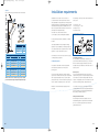
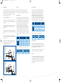
BBT1253 G_CDi Rg+Sys TS c08_07
25/6/07
09:21
Page 1
The Greenstar CDi gas-fired
condensing regular & system
boiler series
Technical and specification information
Voted Domestic Heating Product of the Year in 2005 & 2006
1
BBT1253 G_CDi Rg+Sys TS c08_07
25/6/07
09:21
Page 2
Worcester, Bosch Group
headquarters
Worcester and you. Making a difference.
Working together for many years, heating
We’re a leading British company,
“At Worcester we recognise the vital role
Contents
professionals and Worcester have been
employing more than 1,800 people at our
you, our customer, has in the specification
The Greenstar CDi gas-fired condensing
making a real difference in hundreds of
headquarters and manufacturing plants in
and installation of ‘A’ rated, energy efficient
regular & system boiler series
thousands of homes across the UK. We are
Worcester and at Clay Cross in Derbyshire,
appliances in homes across the UK. We will
Optional plug-in controls
recognised as a market leader in high
including a nationwide network of over 300
continue to invest in our products, people,
Technical data
10
efficiency, condensing boiler technology and
Service Engineers and over 60 technically-
facilities and added value services such as
The inside story
11 - 12
are also committed to providing renewable
trained Field Sales Managers.
training, to give you the support you require
Installing the Greenstar CDi regular & system
13 - 17
in providing a total solution for your
boiler series
customers’ comfort.”
Greenstar CDi series horizontal fluing options
energy solutions.
As part of Europe’s largest supplier of
4-7
8-9
18 - 21
As part of the Bosch Group, our products are
heating products, Worcester, Bosch Group
Greenstar CDi series vertical fluing options
22 - 24
designed and manufactured to provide the
has the UK-based resources and support
Richard Soper,
Plume management system options
25 - 28
high levels of quality and reliability which are
capability to offer you the value-added
Managing Director, Worcester, Bosch Group
Installation requirements
29 - 31
synonymous with the Bosch name
solutions we feel you deserve.
The Greenstar CDi series accessories
32 - 33
throughout the world.
2
Page
After-sales
37
Worcester training
38 - 39
3
BBT1253 G_CDi Rg+Sys TS c08_07
25/6/07
09:21
Page 4
The Greenstar CDi condensing
regular & system boiler series
The Greenstar CDi regular
& system series at a glance
time – but the advanced new series of Greenstar CDi
Hence SEDBUK Band A ratings for all models in the new
Greenstar CDi condensing range.
Conventional and system condensing boilers from
Output kW
to DHW
Min
Max
Primary temperature
control
9.4kW
7.7kW
30kW
40kW
30kW
•
•
•
•
•
•
•
•
•
•
•
A
A
Greenstar CDi condensing boilers deliver this energy-saving
such a notion.
performance by ingeniously recycling exhaust gases to
Modulating control
extract and re-use the latent heat – a highly efficient use of
Natural gas
Here is a ground-breaking range of energy-saving boilers
energy which also significantly reduces carbon dioxide
LPG
which is very good news for the environment and excellent
emissions into the atmosphere.
Electronic ignition
•
•
•
•
SEDBUK band
A
alike.
To all these major benefits you can add yet more:
superlative Worcester quality and reliability; a range of
HE stands for Higher Efficiency and for
outputs to satisfy the heating demands of a range of
Highly Cost Effective
households; and truly exceptional all-round value for money.
30CDi
System
7.7kW
Worcester has so much to offer that it’s already disproving
news for specifiers, developers, installers and consumers
Benefits
Aluminium silicon heat
High efficiency
exchanger
30CDi
40CDi
Conventional Conventional
It’s often said that you can’t please everybody all of the
Features
SEDBUK Band A
High efficiency –
money saving
Wall mounting jig
Allows pre-fabrication
of system
Compact dimensions
Space saving, ease of siting
Anti-cycle control
Energy saving
Electronic ignition
Energy saving
Built-in frost protection
Money saving,
economical protection
Multi-directional fluing
Siting flexibility
No ventilation grilles required
Money and labour saving
for compartment installations
Fault finding diagnostics and
Time saving
The Greenstar CDi condensing boilers have an average
service modes displayed
annual efficiency (SEDBUK value) of over 90%, efficiently
Operational status indicator
Consumer friendly
Class 5 NOx levels
Environmentally friendly
Variable pump speed*
Automatically adjusts to
producing heat for your heating and/or hot water system.
Other types of boiler achieve around 78% efficiency.
Therefore, compared with a new conventional boiler,
meet system flow demand
Greenstar CDi condensing boilers can cut heating and hot
water bills and it’s cheaper to run than an older boiler.
Intelligent System Package*
No electrician required
Pump seizure protection*
Prevents call backs
*30CDi System boiler only
4
5
BBT1253 G_CDi Rg+Sys TS c08_07
25/6/07
09:21
Page 6
The Greenstar CDi condensing regular & system boiler series
The CDi regular and system series design benefits
Versatility
in operation
The Worcester Greenstar CDi Conventional is a wall-
Gas
mounted, gas-fired condensing ‘heating only’ or regular
boiler. The appliance combines, within one casing, a
Whenever a demand for DHW or CH is made, the boiler’s
The Greenstar CDi regular and system series are available for
boiler layout
electronic control system is energised and the burner
use with both natural gas and LPG.
Feed and
expansion
cistern
cast-aluminium heat exchanger, fan, gas valve and other
electronic and mechanical equipment necessary to provide
Regular
electronically ignites via a flame ionisation system.
Cold water
storage cistern
Controls
The pre-mix burner automatically adjusts to the set level.
central heating.
Hot water cylinder
Hot water to baths,
showers and basins etc
It is particularly suited to an older system which may not
sustain the higher pressures a system or combi boiler
operates under. With a feed and expansion cistern in the
Pump
Motorised
valve
customer setting by the fascia mounted variable control.
Room
thermostat
Programmer
Worcester
regular boiler
(TRVs closing down, etc.) and the flow temperature exceed
the customer setting then the burner will modulate
unlike a sealed system which requires manual filling.
downwards to match the system demand level. Should the
flow temperature continue to rise then the burner will be
efficient unit giving all the heating and hot water required,
System boiler
anti-cycle mode and not allow the appliance to re-fire for a
with significant savings on running and installation costs.
layout
set period.
(System boiler
with low
pressure hot
water cylinder)
Options
The Greenstar 30CDi System boiler incorporates all the
Cold water
storage cistern
and modulating pump. All components are pre-wired, pre-
Hot water cylinder
• An integral fascia with status display lights and a digital
display which also operates as a fault diagnosis display.
• DHW control for use with Intelligent System Package*.
Fluing
Hot water to baths,
showers and basins etc
Pump
quicker and neater installation.
A condensing boiler is more efficient due to its ability to
• Variable temperature control selector.
de-energised and the control system will go into an
The Greenstar 30CDi System boiler is a compact and highly
plumbed and pre-tested for greater reliability as well as
• Power on/off switch.
Should the system requirements reduce during operation
roof space, any ‘topping up’ of the system is automatic,
major components built-in, including an expansion vessel
The Greenstar CDi Conventional series features:
The flow temperature of the boiler is then maintained at the
Motorised
valve
The Greenstar CDi series features 2 different sizes of
Room
thermostat
multi-directional RSF flue systems, 100mm or 125mm.
Worcester
system boiler
with programmer
extract more heat from the flue gases normally lost to the
The flue can be run horizontally or vertically with additional
environment through the flue system.
90 or 45 degree in-line bends allowing changes of route or
Greenstar CDi
System model
direction, providing an extremely flexible and versatile fluing
system enabling the appliance to be sited virtually
All the Greenstar CDi models use the same AluminiumSilicon heat cell with an extra large surface area.
System
anywhere.
boiler layout
As the flue gases pass through the heat exchanger this extra
(System boiler
with unvented
hot water
cylinder)
surface area cools the flue gases to around 55°C
whereupon the latent heat within, which would normally be
lost to the atmosphere, is instead released and applied to
Hot water cylinder
Hot water to baths,
showers and basins etc
Pump
the system.
It is this ability to extract as much heat as possible from the
gas it burns that gives the Greenstar CDi series an
More details are shown on page 18.
Motorised
valve
Room
thermostat
Worcester
system boiler
with programmer
Cold mains
exceptionally high level of operating efficiency.
This higher efficiency is recognised within section L of the
Building Regulations, subsequently achieving a higher SAP
or NHER rating.
*30CDi System boiler only
6
7
BBT1253 G_CDi Rg+Sys TS c08_07
25/6/07
09:21
Page 8
Optional plug-in controls for the
Greenstar 30CDi System boiler when
used with optional diverter valve kit
The Greenstar 30CDi System boiler is available with a comprehensive range of easy-to-use
Intelligent system package (30CDi System only)
controls. All fascia mounted controls offer simple plug-in connection to the boiler
An optional package for Greenstar CDi system boilers. The combination of the TD200
circuit board.
text display and RT10 room thermostat with a built-in diverter valve motor provides an
intelligent control upgrade with easy-to-use features. Please note this cannot be used on
under-floor heating. The RT10 is not available separately.
DT20RF digital RF thermostat with twin channel programmer
A wall-mounted RF room thermostat with digital display, combined with a twin channel
Part of the Intelligent System Package, the TD200 text display is a seven day programmer.
digital timer in the boiler fascia. The fascia mounted programmer benefits from automatic
It is easy-to-use with automatic time and date setup, automatic summer/winter time
time and date setup, automatic summer/winter time changeover and a backlight for use in
changeover and a backlight for use in low light conditions. Three on/off periods can be set
low light conditions.
per day. The TD200 can be fascia mounted or hard wired outside the boiler using the
optional wall mounting socket. The TD200 features an easy-to-use full text display providing
DT20 twin channel digital programmer
more information than standard digital controls. A hard wired room thermostat is available
A versatile, easy-to-learn, 7 day, digital programmer offering up to 3 on/off settings per day.
to provide optimum start functionality. The TD200 is not available separately.
The programmer has a host of innovative features including automatic setup, which sets
the correct time and date at power-up, automatic summer/winter time changeover and a
A hard wired optimising room temperature controller with digital display for use with the
green backlight for use in low light conditions.
TD200. The display shows current and desired temperature and an advance button allows
the user to move to the next heating switch point on the TD200.
DT10RF digistat
A familiar wall-mounted 24 hour programmable RF digital thermostat combined with a
fascia mounted single channel programmer to time the hot water cylinder. The programmer
includes a built-in receiver for the room thermostat and all of the functionality of the DT20.
Wall mounting socket
A Worcester branded wall mounting socket which allows the TD200 to be hard wired away
from the boiler.
DT10RF optimiser
A seven day digital programmable RF thermostat with a seven day programmer/ receiver in
the boiler fascia. The transmitter is the tried and tested optimiser as available with other
Worcester boilers. The optimum start feature, where the thermostat delays the firing of the
boiler until necessary, is a useful energy-saving option.
Increased SAP ratings
As well as the CDi models achieving very high SAP ratings
for dwellings, the addition of the optimising temperature
controller further increases these ratings as well as being
part of the recommended best practice, as covered by the
CHESS design standard.
8
TD200 text display
9
BBT1253 G_CDi Rg+Sys TS c08_07
25/6/07
09:21
Page 10
Technical data – Greenstar CDi regular & system series
Model
Greenstar 30CDi
Conventional
Greenstar 40CDi
Conventional
Greenstar 30CDi
System
Height (mm)
760 (max)
760 (max)
760 (max)
Width (mm)
440
440
440
Depth (mm)
360 (max)
360 (max)
360 (max)
39.5
39.5
46.5
90.3%/Band A
90.2%/Band A
90%/Band A
Heating flow/return connections
22mm compression
22mm compression
22mm compression
Condensate connection
22mm plastic pipe
22mm plastic pipe
22mm plastic pipe
Gas connection
22mm compression
22mm compression
22mm compression
7.7 - 30
9.4 - 40.8
7.7 - 30
(26,272 - 102,360)
(32,073 - 139,210)
(26,272 - 102,360)
•
•
•
Plug-in timers
–
–
•
(optional)
Optimising room
temperature controller
–
–
•
(optional)
Intelligent controls
–
–
•
(optional)
Modulating pump
–
–
Fault diagnostic display
•
•
•
•
Flow and return pipes supplied to
allow pipes behind installation
•
•
•
Max. vertical flue (mm)
(100mm dia) inc. terminal
9,400
4,900
9,400
Max. vertical flue (mm)
(125mm dia) inc. terminal
18,500
16,000
18,500
Max. horizontal flue (mm)
(100mm dia)
7,900
2,600
7,900
Max. horizontal flue (mm)
(125mm dia)
18,500
12,500
18,500
NOx classification
Class 5
Class 5
Class 5
N/A
N/A
15mm compression
Weight – dry (kg)
SEDBUK value %/band
The Greenstar CDi Conventional
condensing boiler – inside story
3
Output to central heating
kW
(Btu)
Wall mounting jig
PRV connection
•
9
1
2
11
10
5
4
6
8
7
Key to components
8. Digital Display
9. Auto Air Vent
1. Aluminium/Silicon WB5 Heat Exchanger
10. Drain Point
2. Pre-mix Fan
11. Air/Gas Adjustment Screw
3. Down Firing Low NOx Burner
4. Gas Valve
5. Syphon
6. On/Off Button
7. Temperature Control
10
11
BBT1253 G_CDi Rg+Sys TS c08_07
25/6/07
09:21
Page 12
The Greenstar 30CDi System
condensing boiler – inside story
Installing the Greenstar CDi
regular & system boiler series
The Greenstar CDi range is designed for connection to a
Siting of appliance
traditional heating and hot water system. The major
benefits of the Greenstar CDi regular or system boilers are:
General
The appliances are not suitable for external installation.
3
•
The boiler is compatible with S and Y plan systems
•
The boiler comes supplied with a wall mounting bracket
•
WB5 cast aluminium/silicon heat cell
The wall on which the boiler is to be mounted should be
12
capable of supporting an overall weight of approximately
50kg.
The wall does not require special protection. However, if
2
• A syphonic condensate trap is pre-plumbed within
the appliance is to be fitted in a timber frame building the
guidelines laid down in BS 5440:Part 1:2000 and the gas
1
• Built-in pump and expansion vessel*
installer manual Chapter 11, “Gas in Timber Frame
Housing” should be adhered to.
• No feed and expansion cistern in the loft space*
The appliances may be installed into an airing cupboard
11
• Less pipework*
if required. Use a non-combustible perforated material
(max. hole sizes of 13mm) to separate the boiler from the
9
Greenstar CDi boilers are exceptional for their number of
airing space.
additional time saving installation features:
5
Clearances
13
• Built-in frost protection for boiler
4
10
6
14
8
The minimum clearances shown opposite should be allowed
for installation and servicing, and are also the minimum
• Built-in fault finding diagnostics
clearances required for installation into an unventilated
compartment (see below).
• Automatic gas pressure adjustment
• Highly versatile multi-directional fluing system
960mm
450mm
• Combined ignition and control board means fewer
connections
7
• Pre-fabricated pipes allowing top exit from the boiler
• A rigid 22mm compression gas connection eliminating
the need for pre-fabricating the gas pipe onto the
Using 100mm flue kit
- 1,112mm
Using 125mm flue kit
- 1,152mm
isolating valve
Key to components
8. Digital Display
9. Auto Air Vent
1. Aluminium/Silicon WB5 Heat Exchanger
10. Drain Point
2. Pre-mix Fan
11. Air/Gas Adjustment Screw
3. Down Firing Low NOx Burner
12. Expansion Vessel
4. Gas Valve
13. Modulating Pump
5. Syphon
14. Plug-in Control
• The large output range capability of the appliances
6. On/Off Button
7. Temperature Control
*30CDi System boiler
12
13
BBT1253 G_CDi Rg+Sys TS c08_07
25/6/07
09:21
Page 14
Greenstar CDi Conventional
Compartment installation
Condensate termination and route
External condensate pipework
The appliance may be installed in any room, although
The condensate connection on Worcester appliances is in
All Worcester condensing boilers have within a syphonic
particular attention is drawn to the requirements of the IEE
22mm plastic. The pipe should be extended and directed
condensate trap. Rather than the condensate constantly
A Flow
22mm
regulations applicable and in Scotland the electrical
away from the appliance with a constant minimum fall of
dripping into the discharge pipe, the condensate is
B Gas inlet
22mm
collected into a trap which releases it in 100ml quantities.
C Return
22mm
provisions with respect to installation in a room containing
3 degrees or 50mm in every metre.
a bath or shower.
Pipework connections
This will help prevent freezing occurring.
The condensate pipe can terminate into any one of five areas:
• The room in which the appliance is installed does not
Wherever possible the condensate discharge pipework
require a purpose provided air vent.
should be routed and terminated internally. Should this not
A
B
C
be possible, and the only available route is external, the
• If the appliance is installed in a cupboard or compartment
following conditions should be observed:
Greenstar CDi System
with dimensions that allow the minimum clearances
• The pipework length should be kept to a minimum and
shown in the siting of appliance section above, then no
Wall preparation
Pipework connections
the route as vertical as possible
ventilation is required.
Internal sink/
washing machine drain
Internal waste drainage system
• Where pipework could be subjected to extreme cold or
A Flow
22mm
B Gas inlet
22mm
C Return
22mm
wind chill, a weather proof insulation should be used.
The drawing shows the new CDi wall mounting jig which
Alternatively, the condensate pipework could be
enables a simple and straightforward method of attaching
increased to a minimum 32mm without the requirement
the boiler to the wall surface. The new wall mounting
to insulate.
A
B
C
jig has additional optional fixing points and provides
improved engagement.
After fixing the jig to the wall, the appliance can be lifted
Pipework connections and casing dimensions
Soil and vent stack
External drainage system
Cabinet dimensions (mm)
C
onto the jig and the union connections tightened. The
A
750*
pipework can be routed behind the boiler without the
B
440
C
360
need for an additional wall spacing frame.
*760mm to top of casing front.
A
External condensate absorption point
(unsuitable for clay soil types)
A Condensate from boiler syphon/trap
B Sink with integral overflow
G 300mm x 100mm dia sealed
plastic tube
C 22mm dia plastic condensate pipe
H Ground level
D External drain or gully
J Drainage holes 50mm facing away
from building
E Internal soil and vent stack
F Serviceable condensate trap
(75mm min.)
B
K Limestone chippings
L Weather resistant insulation
Condensate disposal
Whilst all of the above methods are acceptable it is always
All condensing boilers generate condensate discharge
the best practise to terminate the condensate pipe via an
which needs to be piped away from the appliance via a
internal waste system. This will eliminate the need for any
plastic pipe.
external condensate pipe runs which can be susceptible to
freezing in extreme weather. Best practise is not to run
The amount of condensate generated depends on the
external condensate pipe any further than 3m. If it is
efficiency and operating status of the appliance. This can
necessary to run more than 3m externally increase pipe size
be up to 2 litres of condensate water an hour.
to 32mm.
14
15
BBT1253 G_CDi Rg+Sys TS c08_07
25/6/07
09:21
Page 16
Flue terminal positioning
IMPORTANT: any switch or appliance control using mains
Boiler location & clearances
electricity must not be able to be touched by a person
RSF horizontal and vertical
using the bath or shower.
Bathrooms
Terminals adjacent to windows or openings on
pitched and flat roofs
Minimum dimensions of flue terminal positions for balanced room
sealed flues with fanned draught:
Electrical switches, fused spur and socket outlets must not
O
If a mechanical or RF mechanical timer or text display with
The flue should not penetrate
the shaded area
Q
600mm
P
Q
be situated in the bathroom.
room thermostat (IP 20 only) is fitted the boiler can only be
P
600mm
boundary
The boiler can be installed in zones 2 or 3.
installed in zone 3.
All pipework to the appliance must be cross bonded.
A non mechanical timer can be installed in zone 2.
P
R
2000mm
D,E
P
I
See IEE wiring regulations. (See Technical Data for
IP ratings).
P
B
H
F
C
J
N
A
L
600mm
600mm
M
G
H
I
H
750mm
K
The flue system must be installed and terminated in
3
accordance with the recommendations of BS 5440:Part 1.
2
1
1
2
3
2,250mm
General position
Key to illustration
1. The terminal must not cause an obstruction nor the
Terminal position
1
Min. distance
(mm)
A1
Directly below an opening, air brick, opening windows etc
300
B1
Above an opening, air brick, opening window etc
300
C1
Horizontally to an opening, air brick, opening window etc
300
D
Below gutters, soil pipes or drain pipes
75
E
Below eaves
200
F
Below balconies or car port roof (lowest point)
200
G
From a vertical drain pipe or soil pipe
150
H
From an internal or external corner or to a boundary alongside
the terminal
300**
with regards to the pluming of the flue gases and any
increase in noise levels.
2. If a terminal is fitted less than 2 metres above a surface
to which people have access, then a guard must be
600mm
fitted. A terminal protective guard is available from
Tower Flue Components, Vale Rise, Tonbridge.
750mm
Tel: (01732) 351555. The terminal guard must be
securely fixed to the wall using suitable plugs and
300
corrosion resistant screws. The guard must be
I
Above ground, roof or balcony
J
From a surface or boundary facing the terminal
600**
symmetrically positioned about the terminal assembly
K
From a terminal facing the terminal
1,200
and spaced such that there is a gap of 50mm between
L2
From an opening in the car port (e.g. door, window) into
the dwelling
1,200
the end of the terminal and the guard.
M
Vertically from a terminal on the same wall
1,500
N
Horizontally from a terminal on the same wall
O
From a non-combustible vertical structure on the roof
*
condensation will be emitted from the flue terminal and
P
Above intersection with the roof
*
siting where this could be a nuisance, i.e. near security
Q
Adjacent to windows or openings on pitched and flat roofs
R
Below windows or openings on pitched roofs
300
600
1
1
2,250mm
2
3
3. In certain weather conditions, a white plume of
lighting, should be avoided.
2,000
In addition, the terminal should not be nearer than 150mm (fanned draught)
to an opening in the building fabric formed for the purpose of accommodating
a built-in element such as a window frame.
2 Not recommended.
*See instructions supplied with vertical flue kits.
**Care should be taken to ensure terminal siting does not cause a nuisance to
adjacent properties.
16
discharge a nuisance. Particular care should be exercised
4. The air inlet/outlet duct and the terminal of the boiler
600mm radius
must not be closer than 25mm to any combustible
material. Detailed recommendations on protection of
combustible materials are given in BS 5440:1.
17
BBT1253 G_CDi Rg+Sys TS c08_07
25/6/07
09:21
Page 18
Greenstar CDi regular & system
boiler series horizontal fluing options
The Greenstar CDi series has the choice of 2 differently
sized horizontal RSF flue systems, a 100mm diameter
Option 2
Option 3
Extension flue horizontal
Extension flue horizontal using a second 90º bend
Option 1
Maximum total straight flue length
100mm dia
Standard horizontal flue assembly
125mm dia
Maximum total straight flue length
30CDi Conventional 7,900mm 18,500mm
100mm dia
125mm dia
telescopic flue kit and a 125mm diameter kit. Both systems
40CDi Conventional 2,600mm 12,500mm
30CDi Conventional 5,900mm 16,500mm
have different maximum lengths. Options 1 to 6 detail
30CDi System
40CDi Conventional
7,900mm 18,500mm
the permissible lengths.
30CDi System
N/A
10,500mm
5,900mm 16,500mm
Flue components required
Maximum total straight flue length
Horizontal RS flue
100mm dia
125mm dia
30CDi Conventional 570mm 1,070mm
Flue diameter
100mm
125mm
40CDi Conventional 570mm 1,070mm
Minimum flue length
350mm*
250mm
30CDi System
30CDi Conventional
7,900mm
18,500mm
40CDi Conventional
2,600mm
12,500mm
30CDi System
7,900mm
18,500mm
Maximum flue length
100mm dia standard telescopic flue kit
Comprises:
570mm 1,070mm
Flue components required
Flue Diameter
Description
Quantity
Worcester Part No.
30CDi Conventional
570mm (100mm dia) of flue duct
Part No. 7 716 191 082
1,030mm (125mm dia) of flue duct including terminal
(as measured from centre of flue outlet)
Worcester Part No.
60/100mm
Standard Telescopic
Flue Kit
1
7 716 191 082
60/100mm
1,000mm Extension Kit
up to 8
7 716 191 083
125mm
Standard Flue Kit
1
125mm
Flue Extension
up to 18
7 719 002 350
60/100mm
1,000mm Extension Kit
up to 6
7 716 191 083
7 719 001 892
60/100mm
90º Bend
1
7 716 191 084
125mm
Standard Flue Kit
1
7 719 002 350
125mm
Flue Extension
up to 17
7 719 001 892
125mm
90º Bend
1
7 719 001 891
1
7 716 191 082
125mm
Standard Flue Kit
1
7 719 002 350
60/100mm
1,000mm Extension Kit
up to 3
7 716 191 083
125mm
Standard Flue Kit
1
7 719 002 350
125mm
Flue Extension
up to 12
7 719 001 892
125mm
Standard Flue Kit
1
7 719 002 350
125mm
Standard Telescopic
Flue Kit
Standard Flue Kit
1
1
7 716 191 082
7 719 002 350
30CDi Conventional
7 716 191 082
Standard Telescopic
Flue Kit
7 716 191 082
Worcester Part No.
1
60/100mm
1
Quantity
Standard Telescopic
Flue Kit
7 716 191 082
Standard Telescopic
Flue Kit
Description
60/100mm
1
60/100mm
Flue components required
Flue Diameter
30CDi Conventional
60/100mm
60/100mm
1 x flue turret elbow
Quantity
40CDi Conventional
30CDi System
125mm dia standard flue kit
Description
Standard Telescopic
Flue Kit
40CDi Conventional
1 x flue turret elbow
Flue Diameter
30CDi System
60/100mm
Standard Telescopic
Flue Kit
1
7 716 191 082
60/100mm
1,000mm Extension Kit
up to 8
7 716 191 083
125mm
Standard Flue Kit
1
7 719 002 350
125mm
Flue Extension
up to 18
7 719 001 892
40CDi Conventional
125mm
Standard Flue Kit
1
7 719 002 350
125mm
Flue Extension
up to 11
7 719 001 892
125mm
90º Bend
1
7 719 001 891
60/100mm
Standard Telescopic
Flue Kit
1
7 716 191 082
60/100mm
1,000mm Extension Kit
up to 6
7 716 191 083
1
7 716 191 084
30CDi System
60/100mm
90º Bend
Part No. 7 719 002 350
125mm
Standard Flue Kit
1
7 719 002 350
*Can be cut to 130mm. Please refer to instructions.
125mm
Flue Extension
up to 17
7 719 001 892
125mm
90º Bend
1
7 719 001 891
Accessories
Worcester Part No.
100mm dia
125mm dia
Extension Flue Kit (1,000mm) 7 716 191 083
7 719 001 892
90º Bend
7 716 191 084
7 719 001 891
45º Bend
7 716 191 085
7 719 001 899
Vertical Flue Adaptor Kit
7 719 002 432
7 719 002 433
Support Bracket Kit
7 716 191 092
–
The following criteria should be noted when planning the
installation.
• The concentric flue system must be inclined at 3º
(50mm per metre) from the appliance, to allow
condensate to drain back into the boiler.
• Because the appliance operates at high efficiency a
white plume of condensation will be emitted from the
terminal. Care must be taken when selecting the flue
terminal position.
18
19
BBT1253 G_CDi Rg+Sys TS c08_07
25/6/07
09:21
Page 20
Option 4
Option 5
Option 6
Extension flue horizontal and upwards
Extension flue upwards and horizontal using a second
Extension flue upwards and horizontal using a third
90º bend
90º bend
Maximum total straight flue length
100mm dia
125mm dia
30CDi Conventional 7,900mm 18,500mm
40CDi Conventional 2,600mm 12,500mm
30CDi System
Maximum total straight flue length
7,900mm 18,500mm
100mm dia
Flue components required
Flue Diameter
Description
125mm dia
Maximum total straight flue length
30CDi Conventional 5,900mm 16,500mm
Quantity
40CDi Conventional
Worcester Part No.
30CDi System
N/A
100mm dia
10,500mm
5,900mm 16,500mm
40CDi Conventional
30CDi Conventional
30CDi System
60/100mm
Standard Telescopic
Flue Kit
1
7 716 191 082
60/100mm
1,000mm Extension Kit
up to 8
7 716 191 083
60/100mm
90º Bend
1
7 716 191 084
60/100mm
Vertical Flue Adaptor
1
7 719 002 432
Flue Diameter
1,000mm Extension Kit
up to 6
7 716 191 083
90º Bend
1
Flue Extension
up to 19
7 719 001 892
60/100mm
Description
Quantity
Worcester Part No.
7 716 191 082
30CDi Conventional
60/100mm
Standard Telescopic
Flue Kit
1
7 716 191 084
60/100mm
1,000mm Extension Kit
up to 4
7 716 191 083
90º Bend
3
7 716 191 084
7 719 001 891
60/100mm
Vertical Flue Adaptor
1
7 719 002 432
60/100mm
7 719 002 433
125mm
Standard Flue Kit
1
7 719 002 350
60/100mm
Vertical Flue Adaptor
1
7 719 002 432
125mm
Flue Extension
up to 18
7 719 001 892
125mm
Standard Flue Kit
1
7 719 002 350
125mm
90º Bend
2
7 719 001 891
125mm
Flue Extension
up to 17
7 719 001 892
7 719 002 433
125mm
90º Bend
3
7 719 001 891
125mm
Vertical Flue Adaptor
1
7 719 002 433
40CDi Conventional
60/100mm
Standard Telescopic
Flue Kit
1
7 716 191 082
60/100mm
1,000mm Extension Kit
up to 3
7 716 191 083
125mm
60/100mm
90º Bend
1
7 716 191 084
60/100mm
Vertical Flue Adaptor
1
7 719 002 432
125mm
Standard Flue Kit
1
7 719 002 350
125mm
Flue Extension
up to 13
7 719 001 892
125mm
90º Bend
1
7 719 001 891
125mm
Vertical Flue Adaptor
1
7 719 002 433
30CDi System
20
7 716 191 082
125mm
1
8,500mm
Flue components required
Flue Diameter
1
7 719 002 350
Vertical Flue Adaptor
Worcester Part No.
Standard Telescopic
Flue Kit
1
125mm
Quantity
60/100mm
Standard Flue Kit
1
Description
30CDi Conventional
125mm
90º Bend
N/A
3,900mm 14,500mm
Flue components required
60/100mm
125mm
125mm dia
30CDi Conventional 3,900mm 14,500mm
60/100mm
Standard Telescopic
Flue Kit
1
7 716 191 082
60/100mm
1,000mm Extension Kit
up to 8
7 716 191 083
60/100mm
90º Bend
1
7 716 191 084
60/100mm
Vertical Flue Adaptor
1
7 719 002 432
125mm
Standard Flue Kit
1
7 719 002 350
125mm
Flue Extension
up to 19
7 719 001 892
125mm
90º Bend
1
7 719 001 891
125mm
Vertical Flue Adaptor
1
7 719 002 433
Vertical Flue Adaptor
1
40CDi Conventional
40CDi Conventional
125mm
Standard Flue Kit
1
7 719 002 350
125mm
Flue Extension
up to 12
7 719 001 892
125mm
Standard Flue Kit
1
7 719 002 350
125mm
90º Bend
2
7 719 001 891
125mm
Flue Extension
up to 11
7 719 001 892
125mm
Vertical Flue Adaptor
1
7 719 002 433
125mm
90º Bend
3
7 719 001 891
125mm
Vertical Flue Adaptor
1
7 719 002 433
7 716 191 082
30CDi System
60/100mm
Standard Telescopic
Flue Kit
1
7 716 191 082
60/100mm
1,000mm Extension Kit
up to 6
7 716 191 083
60/100mm
90º Bend
1
30CDi System
60/100mm
Standard Telescopic
Flue Kit
1
7 716 191 084
60/100mm
1,000mm Extension Kit
up to 4
7 716 191 083
90º Bend
3
7 716 191 084
60/100mm
Vertical Flue Adaptor
1
7 719 002 432
60/100mm
125mm
Standard Flue Kit
1
7 719 002 350
60/100mm
Vertical Flue Adaptor
1
7 719 002 432
125mm
Flue Extension
up to 18
7 719 001 892
125mm
Standard Flue Kit
1
7 719 002 350
125mm
90º Bend
2
7 719 001 891
125mm
Flue Extension
up to 17
7 719 001 892
7 719 002 433
125mm
90º Bend
3
7 719 001 891
125mm
Vertical Flue Adaptor
1
7 719 002 433
125mm
Vertical Flue Adaptor
1
21
BBT1253 G_CDi Rg+Sys TS c08_07
25/6/07
09:21
Page 22
Minimum height
Greenstar CDi regular & system
boiler series vertical fluing options
The Greenstar CDi series have the choice of 2 differently
sized vertical RSF flue systems, 100mm and 125mm. Both
systems have different maximum lengths. Options 1 to 3
detail the permissible lengths.
125mm
Flue terminal assembly diameter
135mm
135mm
Flat roof
300mm
Pitc
roo hed
f
L = 100mm dia 1,140mm
L = 125mm dia 1,365mm
Maximum total straight flue length
(inc. terminal)
500mm
Flat roof
L = 100mm dia 1,140mm
L = 125mm dia 1,365mm
Flue components required
Flue Diameter
Description
Quantity
Worcester Part No.
30CDi Conventional
Straight flue length
Maximum flue length (inc. terminal)
100mm
Vertical Flue Kit
1
7 719 002 430
Flue components required
125mm
Vertical Flue Kit
1
7 719 002 431
Flue Diameter
100mm dia 125mm dia
30CDi Conventional
7,400mm 16,500mm
40CDi Conventional
2,900mm 14,000mm
30CDi System
7,400mm 16,500mm
Description
Quantity
Worcester Part No.
30CDi Conventional
40CDi Conventional
30CDi Conventional
9,400mm
18,500mm
40CDi Conventional
4,900mm
16,000mm
100mm
Vertical Flue Kit
1
7 719 002 430
100mm
Vertical Flue Kit
1
7 719 002 430
30CDi System
9,400mm
18,500mm
125mm
Vertical Flue Kit
1
7 719 002 431
100mm
Flue Extension
up to 8
7 719 002 349
1,140mm
1,365mm
Flue terminal assembly length
Maximum total straight flue length
(inc. terminal)
100mm dia 125mm dia
Vertical balanced flue kit
30CDi Conventional
9,400mm 18,500mm
Comprises:
40CDi Conventional
4,900mm 16,000mm
1 x flue terminal assembly
30CDi System
9,400mm 18,500mm
1 x weather sealing collar
Flue components required
1 x fire stop spacer
Flue Diameter
1 x vertical adaptor
Part No. 7 719 002 431 (125mm dia)
Accessories
Worcester Part No.
100mm dia
Description
Quantity
Worcester Part No.
30CDi Conventional
Part No. 7 719 002 430 (100mm dia)
125mm dia
Extension Flue Kit (1,000mm) 7 716 191 083
7 719 001 892
90º Bend
7 716 191 084
7 719 001 891
45º Bend
7 716 191 085
7 719 001 899
30CDi System
100mm
Vertical Flue Kit
1
7 719 002 430
125mm
Vertical Flue Kit
1
7 719 002 431
100mm
45º Bend
2
7 719 002 347
125mm
Vertical Flue Kit
1
7 719 002 431
125mm
Flue Extension
up to 17
7 719 001 892
125mm
45º Bend
2
7 719 001 899
40CDi Conventional
100mm
Vertical Flue Kit
1
7 719 002 430
100mm
Flue Extension
up to 3
7 719 002 349
100mm
45º Bend
2
7 719 002 347
Vertical Flue Kit
1
7 719 002 431
100mm
Vertical Flue Kit
1
7 719 002 430
125mm
100mm
Flue Extension
up to 9
7 719 002 349
125mm
Flue Extension
up to 14
7 719 001 892
125mm
Vertical Flue Kit
1
7 719 002 431
125mm
45º Bend
2
7 719 001 899
125mm
Flue Extension
up to 18
7 719 001 892
100mm
Vertical Flue Kit
1
7 719 002 430
40CDi Conventional
30CDi System
100mm
Vertical Flue Kit
1
7 719 002 430
100mm
Flue Extension
up to 8
7 719 002 349
100mm
Flue Extension
up to 5
7 719 002 349
100mm
45º Bend
2
7 719 002 347
125mm
Vertical Flue Kit
1
7 719 002 431
125mm
Vertical Flue Kit
1
7 719 002 431
7 719 001 892
125mm
Flue Extension
up to 17
7 719 001 892
125mm
45º Bend
2
7 719 001 899
125mm
Flue Extension
up to 16
Note: The roof flashing is not supplied by Worcester.
30CDi System
22
Vertical balanced flue system with two 45º bends
500mm
Vertical balanced flue system maximum height
300mm
100mm
Option 2
Option 1
Vertical RSF flue
Flue diameter
Pitc
roo hed
f
100mm
Vertical Flue Kit
1
7 719 002 430
100mm
Flue Extension
up to 9
7 719 002 349
125mm
Vertical Flue Kit
1
7 719 002 431
125mm
Flue Extension
up to 18
7 719 001 892
23
BBT1253 G_CDi Rg+Sys TS c08_07
25/6/07
09:21
Page 24
Option 3
Plume management system options
Vertical balanced flue system with two 90º bends
Plume management system
Condensfit II telescopic flue and plume management
system measuring
Standard plume management system
The flue terminal outlet has built-in stops to limit rotation
Fig A
for horizontal fluing to allow condensate to run back into
Maximum total straight flue length
(inc. terminal)
30CDi Conventional
40CDi Conventional
30CDi System
100mm dia 125mm dia
5,400mm 14,500mm
N/A
the boiler for safe disposal. Do not attempt to force beyond
the limit stops.
12,000mm
5,400mm 14,500mm
500mm
(min) (M)
L (max)
All plume management sections must rise by at least
173mm per metre (10º) from the terminal to ensure that
Flue components required
Flue Diameter
Description
condensate flows back into the boiler.
Quantity
Worcester Part No.
30CDi Conventional
100mm
Vertical Flue Kit
1
7 719 002 430
100mm
Flue Extension
up to 7
7 719 002 349
100mm
90º Bend
2
7 719 002 348
125mm
Vertical Flue Kit
1
7 719 002 431
125mm
Flue Extension
up to 16
7 719 001 892
125mm
90º Bend
2
7 719 001 891
Fig B
500mm (M)
40CDi Conventional
4,500mm
(max) (M)
125mm
Vertical Flue Kit
1
7 719 002 431
125mm
Flue Extension
up to 13
7 719 001 892
125mm
90º Bend
2
7 719 001 891
100mm
Vertical Flue Kit
1
7 719 002 430
100mm
Flue Extension
up to 7
7 719 002 349
100mm
90º Bend
2
7 719 002 348
125mm
Vertical Flue Kit
1
7 719 002 431
125mm
Flue Extension
up to 16
7 719 001 892
Re-directing flue discharge from a 60mm dia plume
125mm
90º Bend
2
7 719 001 891
management outlet
L (max)
30CDi System
Effective straight flue lengths for telescopic flue with
plume management
Model
Min. 1,500mm
Opening in building
e.g. window
Direction of
flue discharge
30CDi Conventional**
40CDi Conventional**
30CDi System**
Direction of
Fig. A
Fig. B
Max. straight flue
Max. straight flue
length (L) with min.
length (L) with max.
plume management
plume management
length (M)* (mm)
length (M)* (mm)
5,450
2,650
600
N/A
5,450
2,650
flue discharge
NOTE:
Plume management minimum straight length = 500mm
Min. 1,500mm
Opening in building
e.g. window
Plume management maximum straight length = 4,500mm
**For every additional 1,000mm of plume management
length (M), reduce flue length (L) by 700mm – see figures
A and B.
24
25
BBT1253 G_CDi Rg+Sys TS c08_07
25/6/07
09:21
Page 26
100mm dia horizontal telescopic flue lengths with a
60mm dia plume management system
Option 1
Option 3
Option 4
Plume management system
Plume management system with extensions and 45º bend
Plume management system with angled termination
The maximum effective straight flue lengths (L) are stated
opposite for the relevant appliance together with the
minimum and maximum lengths (M) of the plume
management system connected, these lengths must not
Maximum total straight plume length
be exceeded.
30CDi Conventional
500mm*
40CDi Conventional
500mm*
30CDi System
500mm*
60mm dia
60mm dia plume management system
To ensure that the maximum total straight flue length along
the plume management route is not exceeded the following
Flue components required
Flue Diameter
should be added to dimension (M):
Maximum total straight plume length
Description
Quantity
60mm dia
Worcester Part No.
30CDi Conventional
30CDi Conventional
• 1,500mm for each extra 90º bend
• 750mm for each extra 45º bend
60mm
40CDi Conventional
Plume Management Kit
1
7 716 191 086
For plume management options with 60mm dia extensions
refer to pages 26 – 28.
Plume Management Kit
1
7 716 191 086
60mm dia
Flue components required
Flue Diameter
Description
Quantity
Worcester Part No.
30CDi Conventional
Plume Management Kit
1
7 716 191 086
60mm
Plume Management Kit
1
7 716 191 086
Example, Greenstar 30CDi:
*NOTE: You must refer to the table on page 25 to calculate
60mm
1,000mm Extension
up to 4
7 716 191 087
Required plume management length (M) is 2,500mm, which
your horizontal flue lengths and plume management length.
60mm
45º Bend
1
7 716 191 089
is kit (500mm) plus 2 x 1,000mm extensions. Therefore,
flue length (L) must be reduced by 2 x 700mm, giving a
maximum allowed straight length (L) of:
Plume management system with extensions
4,500mm*
N/A
30CDi System
4,500mm*
Quantity
Worcester Part No.
Flue components required
Flue Diameter
Description
30CDi Conventional
30CDi System
Option 2
60mm
Plume Management Kit
1
7 716 191 086
60mm
1,000mm Extension
up to 4
7 716 191 087
60mm
45º Bend
1
7 716 191 089
Maximum possible straight flue length
7,000mm
Required length of plume management
-2,500mm
*NOTE: You must refer to the table on page 25 to calculate
Minus reduction factor of 2 x 700mm
-1,400mm
your horizontal flue lengths and plume management length.
Maximum available straight flue length
30CDi Conventional
40CDi Conventional
30CDi System
60mm
N/A
3,750mm*
Maximum total straight plume length
40CDi Conventional
60mm
30CDi System
3,750mm*
60mm
Plume Management Kit
1
7 716 191 086
60mm
1,000mm Extension
up to 4
7 716 191 087
30CDi System
60mm
Plume Management Kit
1
7 716 191 086
60mm
1,000mm Extension
up to 4
7 716 191 087
*NOTE: You must refer to the table on page 25 to calculate
3,100mm
your horizontal flue lengths and plume management length.
Maximum total straight plume length
60mm dia
30CDi Conventional
4,500mm*
40CDi Conventional
N/A
30CDi System
4,500mm*
Quantity
Worcester Part No.
Flue components required
Flue Diameter
Description
30CDi Conventional
60mm
Plume Management Kit
1
7 716 191 086
60mm
1,000mm Extension
up to 4
7 716 191 087
30CDi System
60mm
Plume Management Kit
1
7 716 191 086
60mm
1,000mm Extension
up to 4
7 716 191 087
*NOTE: You must refer to the table on page 25 to calculate
your horizontal flue lengths and plume management length.
26
27
BBT1253 G_CDi Rg+Sys TS c08_07
25/6/07
09:21
Page 28
Option 5
Plume management system with extensions and 45º bends
Installation requirements
Installation of the Greenstar CDi series must be in
The following is a list of major items which must be fitted
accordance with the relevant requirements of the Gas
to the system:
Safety (Installation Use) Regulations (as amended), current
IEE Wiring Regulations, local Building Regulations, Building
1. Safety valve – 3bar
Standards (Scotland) regulations and bylaws of the local
2. Pressure gauge – 0 - 4bar
Water company and Health and Safety Document No. 635
3. Expansion vessel
(Electricity at Work Regulations 1989).
4. Automatic air vent
It should be in accordance with the relevant
recommendations of the following British Standards:
Typical fully pumped sealed system
BS 6798; BS 5449; BS 5546:1; BS 5440:1; BS 5440:2;
BS 6891.
Maximum total straight plume length
60mm dia
30CDi Conventional
40CDi Conventional
appliances must be installed by a CORGI registered person
N/A
in accordance with the above regulations. Failure to install
30CDi System
3,000mm*
Quantity
Worcester Part No.
Flue components required
Flue Diameter
Description
Gas Safety (Installation and Use) Regulations. All gas
3,000mm*
appliances correctly could lead to prosecution.
The manufacturer’s notes must not be taken in any way as
overriding statutory regulations.
30CDi Conventional
To comply with the Water Authority requirements, the
60mm
Plume Management Kit
1
7 716 191 086
60mm
1,000mm Extension
up to 3
7 716 191 087
60mm
45º Bend
2
7 716 191 089
30CDi System
60mm
Plume Management Kit
1
7 716 191 086
60mm
1,000mm Extension
up to 3
7 716 191 087
60mm
45º Bend
System filling and make-up
2
7 716 191 089
*NOTE: You must refer to the table on page 25 to calculate
your horizontal flue lengths and plume management length.
Sealed primary systems
system should be filled via a temporary hose connection to
the mains cold water supply, with a double check valve
The appliance is fitted with a manual reset high limit
assembly and test point fitted to the mains water side of a
thermostat and is suitable for use with a sealed
temporary circuit.
primary system.
Valves and joints
The system should be installed in compliance with the
It is very important that all valves and joints are able to
requirements of BS 5449: Part1. The system must be fitted
sustain a working pressure of up to 3bar (45psi). Particular
with a spring loaded safety valve set to operate at 3bar
care should be exercised when fitting radiator valves and
(45 psi) and the pipe connections made through the system
only those of high quality to BS 2767:10 should be used. All
must be capable of sustaining a pressure of up to 3bar.
other valves and fittings should comply with BS 1010.
Manual air vents should be fitted at any high points in
Loss of water pressure from a sealed system will require
the system.
recharging with fresh water and consequential introduction
of air. Air is highly corrosive and will considerably reduce
life expectancy of radiators, pumps etc.
30CDi System diverter valve kit
The 30CDi System boiler can be adapted to house an
in-built diverting valve. The optional valve motor kit allows
the user to control the supply of heat to the hot water
cylinder from the boiler.
28
29
BBT1253 G_CDi Rg+Sys TS c08_07
25/6/07
09:21
Page 30
Plastic pipework
Air supply
Propane gas supply
The use of plastic pipework is acceptable. However, some
Worcester Greenstar CDi boilers are room sealed
The Greenstar CDi series is available in a propane gas
plastics are permeable to oxygen and must be avoided. Only
appliances; the room in which it is installed does not
version. The appliance when on a hot water or full output
pipework with a polymeric barrier should be used. Please
therefore require a purpose provided combustion air vent.
demand will require up to 2.4kg/h (30kW) or 3.3kg/h
note that the first 600mm of pipework connected to the
(40kW) of gas. The gas tank or bottles must be capable of
boiler must be of copper or steel.
Natural gas supply
supplying this quantity of gas at a nominal pressure of
Open vented primary systems
The appliances when on a full output demand will require
37mbar (14.8in wg) at the appliance. The table below
up to
3.2m3/hr
(30kW) or
4.4m3/hr
(40kW) of gas. The gas
The Greenstar CDi Conventional* series is designed for
meter and supply pipes must be capable of supplying this
connection to an open vented fully pumped heating and hot
quantity of gas in addition to the demand from any other
water system.
appliance being served. It is important that a gas supply
shows the propane gas discharge through varying lengths of
pipe and the resistance to flow created by elbows, bends,
etc. Pipe work should be sized to overcome this resistance.
Total length of
gas supply pipe (m)
pipe of at least 22mm diameter is used. Under no
3
6
9
–
1.5
1.01
–
15
discharge
8.0
5.2
4.2
22
m3/h
15.9
8.9
8.3
28
The following points are for guidance only. The system
circumstances should the size of the gas supply pipe be
installation should be carried out in accordance with
less than that of the appliance inlet connection. The meter
Gas
BS 5449:Part1.
outlet governor should be capable of ensuring a dynamic
pressure of 20mbar (8in wg) at the appliance. Particular
The feed and expansion pipes must rise continuously from
consideration should be given to the resistance to gas flow
the appliance and must be of the minimum diameter shown
created by elbows, bends, etc. Pipe work should be sized to
below.
overcome this resistance and details of this are given in the
Pipe diameter
(mm)
rate
Approximate additional length to be allowed (LPG)
table below.
Elbows or tees
The cistern must be arranged to provide a minimum static
Total length of
gas supply pipe (m)
head of 0.25 metres above the top of the highest point in
the heating circuit.
Pipe diameter
(mm)
3
6
9
–
2.9
–
–
15
Air in the appliance is expelled through the vent pipe or
Gas
dissipated into the system. Manual air vents should be
discharge
8.7
5.8
4.6
22
m3/h
18.0
12.0
9.4
28
fitted at any high points in the system.
rate
90º bends
Metres
Feet
Metres
Feet
0.6
2
0.3
1
Electricity supply
A 3amp fused three pin plug and unswitched shuttered
socket outlet (both complying with BS 1362) or preferably a
*30CDi System not suitable for open vent
double pole isolator with a contact separation of 3mm in all
Y plan
Approximate additional length to be allowed (natural gas)
poles supplying the appliance should be used.
F&E
Elbows or tees
AAV
90º bends
The appliance electrical circuits are also protected by an
RT
CYL
CT
IV HC IV
Metres
Feet
Metres
Feet
0.50
2
0.3
1
internal 2amp fuse. The appliance must be earthed.
Warranty
MPV
or
DIV
BC
Worcester Greenstar CDi appliances are offered with a full
B
WV
PR
R
LSV
2 year guarantee* on parts and labour, a 10 year warranty*
on the primary heat exchanger and a 5 year warranty* on
the plate heat exchanger. Ongoing service may be arranged
S plan
through the Worcester Customer Service Department.
*Subject to conditions.
F & EC
AV
RT
CYL
CT
IV HC IV
ZV
ZV
ABV
BC
B
PR
30
WV
R
LSV
31
BBT1253 G_CDi Rg+Sys TS c08_07
25/6/07
09:21
Page 32
Greenstar CDi series accessories
DT20 twin channel
digital programmer*
DT20RF digital RF
thermostat with twin
channel programmer*
DT10RF digistat*
DT10RF optimiser*
Vertical flue adaptor
(100mm dia)
Vertical flue adaptor
(125mm dia)
Support bracket kit
(100mm dia)
Plume management kit
(60mm dia)
Worcester Part No.
7 716 192 038
Worcester Part No.
7 716 192 041
Worcester Part No.
7 716 192 039
Worcester Part No.
7 716 192 040
Worcester Part No.
7 719 002 432
Worcester Part No.
7 719 002 433
Worcester Part No.
7 716 191 092
Worcester Part No.
7 716 191 086
Intelligent
system package*
Text display wall
mounting socket*
RS telescopic flue kit
(100mm dia)
Horizontal flue kit
(125mm dia)
Extension
(100mm dia, 1,000mm)
90º bend
(60mm dia)
45º bend
(60mm dia)
Worcester Part No.
7 719 002 824
Worcester Part No.
7 719 002 718
Worcester Part No.
7 716 191 082
Worcester Part No.
7 719 002 350
Worcester Part No.
7 716 191 087
Worcester Part No.
7 716 191 088
Worcester Part No.
7 716 191 089
Vertical BF kit
(100mm dia)
Vertical BF kit
(125mm dia)
RS extension kit
(100mm dia, 1,000mm)
1m extension
(125mm dia)
Worcester Part No.
7 719 002 430
Worcester Part No.
7 719 002 431
Worcester Part No.
7 716 191 083
Worcester Part No.
7 719 001 892
45º bend
(100mm dia)
45º bend
(125mm dia)
90º bend
(100mm dia)
90º bend
(125mm dia)
Worcester Part No.
7 716 191 085
32
Worcester Part No.
7 719 001 899
Worcester Part No.
7 716 191 084
Worcester Part No.
7 719 001 891
Note: For information on the Condensfit II Telescopic Flue System and
Plume Management Kit, please see dedicated flue Technical and
Specification leaflet 8 716 112 174.
*30CDi System only
33
BBT1253 G_CDi Rg+Sys TS c08_07
Notes
34
25/6/07
09:21
Page 34
Notes
35
BBT1253 G_CDi Rg+Sys TS c08_07
Notes
25/6/07
09:21
Page 36
A complete after-sales service
As part of the worldwide Bosch Group, Worcester strives to
maintain the highest possible standards of after-sales care.
In addition to the no-nonsense parts and labour warranty
All the technical advice
you need
Spares
applicable to all Worcester boilers, you and your customers
have the assurance that every Worcester boiler is
Genuine replacement parts for all Worcester boilers are
manufactured to both the appropriate British and
readily available from stock, on a next day delivery basis.
European standards.
For more information please call your local stockist.
Worcester Contact Centre
Customer Technical Support
Should you require support, our fully trained Contact Centre
The Worcester Technical Helpline is a dedicated phone
staff, based at our head office in Worcester, are ready to
line – committed to providing a comprehensive service to
take your calls. Whatever your query our contact centre
complement the brand name and quality of our boiler
operators along with our nationwide team of engineers
products. Our experienced team of technical experts
are ready to help you.
provides the answers to queries of a technical nature
across the entire Worcester range.
Boiler Protection Options
Worcester also has a pre-sales department, which provides
If you do not offer annual service and maintenance contracts
assistance in selecting a boiler system to suit a particular
please refer your customers to the Worcester Service Centre:
application, along with full guidance on installation. As well
as this we will also assist in finding a recommended
Tel: 08457 256 206
installer. For more information please contact the Technical
Fax: 01905 757 536
Hotline or alternatively visit our website where literature
can be downloaded www.worcester-bosch.co.uk
Contact Centre
Technical
Tel: 08457 256 206
Fax: 01905 754 701
Tel: 08705 266 241
Fax: 01905 752 741
Opening Times
Opening Times
Monday – Friday: 7.00am – 10.00pm
36
Saturday: 8.00am – 5.00pm
Monday – Friday: 7.00am – 8.00pm
Sunday: 9.00am – 12 noon
Saturday: 8.30am – 4.00pm
37
BBT1253 G_CDi Rg+Sys TS c08_07
25/6/07
09:21
Page 38
The very best training programmes
from Worcester
Worcester has always placed great emphasis on technical
Worcester training courses
Worcester training courses
Greenstar CDi, Highflow 440 and HE Plus gas-fired
condensing combi boilers
College-linked Learning
Models covered
Greenstar 27/30/37/42CDi
Greenstar Highflow 440
1 day
support and training for installers and service engineers.
A number of the UK’s leading proactive technical colleges
Today this need is greater than ever. The differences
are equipped with Worcester products and offer excellent
Duration
between a combi, conventional and system boiler are
practical tuition on a more local level.
Greenstar i Junior and Si gas-fired condensing
combi boilers
Distance Learning
Models covered
Greenstar 24/28i Junior
Greenstar 25/30Si
Duration
1 day
substantial, and the technology of each continues to
advance at a rapid pace.
Worcester has produced a selection of Distance Learning
To ensure the highest levels of competence and expertise in
CD ROMs/DVDs which are packed with information.
the installation of all Worcester products, the company
Call 01905 752556 for your copies.
runs intensive training courses for installers, commissioning
engineers and engineers involved with servicing and
Greenstar system and regular gas-fired
condensing boilers
Models covered
Get on course for a more profitable future now.
fault finding.
Courses available
Call now for more information
01905 752526
Our training facilities offer a number of courses suitable for
Duration
12/15/18/24Ri
30/40CDi Conventional
30CDi System
12/24i System
in-depth course for the servicing and fault finding engineers.
Duration
Covering
Key elements of energy-efficient heating and hot
water systems and products, compliance with the
latest Building Regulations, how condensing boilers
work and how they differ to non condensing
products.
Duration
1 day
Unvented Cylinder Course
Covering
All G3 Regulations for the Installation, Servicing and
Commissioning of Unvented Cylinders. The course
includes recognised accreditation by Logic
Certification.
Duration
1 day
Greenskies Solar System
Covering
Installation, Commissioning and Servicing
The course includes recognised accreditation by
Logic Certification for eligibility of low carbon
buildings programme funding.
Duration
2 days
1 day
Standard efficiency boiler course:
i/Si/CDi (non condensing)
Models covered
the installer and commissioning engineers, and a more
Greenstar
Greenstar
Greenstar
Greenstar
Certificate in Energy Efficiency for Domestic
Heating Course
24/28i Junior
24/28Si II
24/28/35CDi
Greenstore Heat Pumps
Covering
Installation, Commissioning and System Design
Duration
2 days
1 day
Greenstar Camray high efficiency condensing
oil-fired boilers
Worcester’s network of regional training centres are
at Clay Cross in Derbyshire, Rochester in Kent and Bangor in
Models covered
Greenstar
Greenstar
Greenstar
Greenstar
Duration
1 day
Danesmoor
Utility
Heatslave
Heatslave External
OFTEC 101
Bangor
Bradford
appliance workshop and a renewable energies workshop in
In addition to these outstanding facilities there are centres
1 day
Camray
Camray Utility
Camray Utility System
Camray External
OFTEC Training
strategically located across the country and include the ‘A’
addition to the extensive gas-fired training facilities.
Duration
Lauder
Training Centres throughout the UK
facility has recently been extended to include an oil-fired
Greenstar
Greenstar
Greenstar
Greenstar
Greenstar Danesmoor & Heatslave high efficiency
condensing oil-fired boilers
Dundee
Rated Training Academy at the company’s headquarters. This
Models covered
Clay Cross
Worcester
Covering
Domestic/Light Commercial Pressure Jet
Commissioning and Servicing
Duration
3 day course (2 days training plus 1 days assessment)
OFTEC 105e
Covering
Domestic/Light Commercial Pressure Jet Boiler
Installation
Duration
1 day assessment
OFTEC 101 & 105e
West Thurrock
Covering
Domestic/Light Commercial Pressure Jet Installation,
Commissioning and Servicing
Duration
3 day course (2 days training plus 1 days assessment
comprising 2 theory and 1 practical)
Northern Ireland. Further ‘A’ Rated Academies are open at
West Thurrock in Essex and Bradford in West Yorkshire as
well as additional training opportunities available throughout
OFTEC 600a
the UK. Please phone 01905 752526 for more information
Covering
Oil Tank Installation and Associated Controls
about a course near you. Each course is run by specialist
Duration
1 day assessment course
trainers and is superbly equipped to deliver a combination
OFTEC 101/105e/600e
of classroom theory and practical hands-on experience
www.worcester-bosch.co.uk
Covering
Domestic/Light Commercial Pressure Jet Boiler
Installation, Commissioning, Servicing and Oil Tank
Installation and Associated Controls
Duration
4 days (2 days training and 2 days assessment)
that’s second to none.
38
39
BBT1253 G_CDi Rg+Sys TS c08_07
25/6/07
09:21
Page 40
Useful numbers
Sales
Service
Tel: 01905 752640
Tel: 08457 256206
Fax: 01905 456445
Fax: 01905 757536
Livingston (Scotland)
Fax: 01506 441687
Spare Parts
Training
Tel: 01905 752576
Tel: 01905 752526
Fax: 01905 754620
Fax: 01905 752535
Technical (Pre & Post Sales)
Literature Line
Tel: 08705 266241
Tel: 01905 752556
Fax: 01905 752741
or download instantly
from our website
www.worcester-bosch.co.uk
In partnership with
The Council for
Registered Gas
Installers
This leaflet is accurate at the date of printing, but may be superseded and should be disregarded if specification and/or appearances
are changed in the interest of continued improvement. The statutory rights of the consumer are not affected.
Part No. 8 716 109 919c (08/07)
Worcester, Bosch Group,
Cotswold Way, Warndon,
Worcester, WR4 9SW
Tel: 01905 754624 Fax: 01905 754619
BBT1253
Worcester, Bosch Group is a brand name of BBT Thermotechnology UK Ltd.