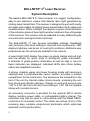
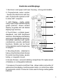
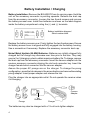
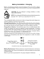
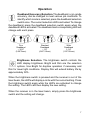
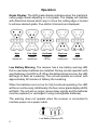
1
Operator's Manual
Laser Receiver
Thank you for purchasing an Apache Technologies, Inc. product.
Your BULLSEYE® 3+ receiver is a premium quality tool that has been
designed and manufactured to provide years of precise and reliable
performance. The system has been specifically designed for use in
harsh construction environments.
This manual is an important part of your purchase as it will familiarize
you with the unit and explain the numerous features that have been
designed into it. Please read this manual thoroughly before using your
BULLSEYE 3+ receiver.
Please contact your Apache dealer or the Apache factory should you
have questions regarding specific applications or if you require
additional information. Contact information is located on the back cover.
Additional contacts are:
Website:
Email:
www.apache-laser.com
[email protected]
[email protected]
Please record your product information below. This will assist you if
there are any questions regarding warranty or service.
PRODUCT:
_______________________
SERIAL NUMBER:
_______________________
DATE OF PURCHASE: _______________________
PURCHASED FROM:
_______________________
PHONE:
_______________________
Contents
BULLSEYE 3+ Laser Receiver
System Description .................................................................... 2
Controls and Displays ................................................................ 3
Battery Installation / Charging .................................................... 4
Operation .................................................................................... 6
Installation .................................................................................. 12
Maintenance and Care ............................................................... 14
Safety ......................................................................................... 14
Specifications ............................................................................. 15
Warranty ..................................................................................... 16
CE Declaration of Conformity ..................................................... 17
P/N ATI-010752-02 REV D
BULLSEYE® 3+ Laser Receiver
System Description
The Apache BULLSEYE 3+ laser receiver is a rugged, multipurpose,
easy-to-use electronic sensor that detects laser light generated by
rotating laser transmitters. The receiver is designed to work with nearly
all makes and models of rotating lasers and will detect both visible and
invisible beams. When installed, the operator is given visual indication
of the reference plane of laser light’s position relative to the cutting edge
of the machine. The receiver can be adapted to many different types
of construction and agricultural machinery.
The BULLSEYE 3+ has several selectable settings. Deadband
size (accuracy) has three settings to meet job site requirements. LED
display brightness can be set to meet light conditions. Additional user
preferences can be set and are detailed in this manual.
A super-bright LED display has green on-grade diodes and red high
and low diodes for quick, easy to distinguish grade information.
5 channels of grade position information as well as high or low lost
beam indication are displayed. Individual LED's also inform battery
status and deadband selection.
A strong, durable upper and lower housing made with aluminum
castings and a polycarbonate center section provides a sealed
compartment for the electronics. The electronics are isolated from the
rest of the unit by internal rubber shock-mounts, protecting the unit
from shock and vibration damage. Clamps on each end securely grip
1.66” to 2.00" (42 mm to 50 mm) round tubing or 1.50" (38 mm) square
tubing with rounded corners.
An accessory connector is provided for the optional RD14 remote
display, machine power cable, or rechargeable battery charger. The
connector may also be used to communicate with the Model CB24+
control box for automatic control. The center two inches (5 cm) of the
receiving area contains proportional photocells which optimizes
automatic control performance.
2
Controls and Displays
1. Aluminum cast upper and lower housing - strong and durable.
2. Polycarbonate center section
- houses the electronics and four
sets of photocells spaced at 90°
to allow 360° reception.
3. LED Display - highly visible
using super-bright diodes display
grade position. Green diodes
display on-grade and red diodes
display high and low.
4. Touch Panel - contains power,
deadband, and LED brightness
switches. Also displays low battery
warning and deadband selection.
Unmarked switches and switch
combinations provide additional
functions. Details can be found
in the operation section beginning
on page 6.
5. Mounting Knobs - attached to
heavy-duty stainless steel clamps
for quick mounting to pipe, square
tubing, or magnetic mount.
1
2
3
4
5
6
7
6. Access Screws - access to battery compartment for replacement
of alkaline or rechargeable batteries.
7. Accessory Connector and Dust Cap - allows cable connection of
optional remote display, machine power cable, or control box cable
for automatic control. Connector is also used to charge rechargeable
batteries.
3
Battery Installation / Charging
Battery Installation: Remove the BULLSEYE from its carrying case. Hold the
unit so the accessory connector is pointing upwards. Remove the dust cap
from the accessory connector. Loosen the two thumb screws and remove
the battery access cover. Install four batteries as shown on the label diagram
inside the battery compartment noting the (+) and (-) terminals.
Battery installation diagram /
Serial number label
Replace the battery access cover. Firmly tighten the two thumbscrews. Ensure
the battery access cover is aligned and fully engaged into the battery housing.
Use a screwdriver if necessary. Replace the accessory connector dust cap.
Nickel Metal Hydride (Ni-MH) Batteries: Batteries are initially shipped fully
charged but the charge may decrease over time prior to first use. They may
require 2 or 3 charging cycles to obtain maximum battery life. To charge, remove
the dust cap from the accessory connector. Insert the cannon adapter into the
receiver accessory connector aligning the slot and connector key. Insert the
charger female barrel connector into the cannon adapter.
Assure the proper AC prongs are on the charger. To change the prong
configuration, press the tab release in the arrow direction and remove the existing
prong adapter. Insert proper adapter and release the tab.
Plug the charger into an appropriate outlet. Do not operate the receiver when
it is charging.
Cannon
Adapter
Prongs
Tab
Release
Charger
The batteries may also be charged with a 12-volt auto lighter adapter.
4
Battery Installation / Charging
Built-in overcharging protection prevents damage if the unit is left on charge
after being fully charged. There is also protection to prevent charging alkaline
batteries.
CAUTION: Do not attempt to charge alkaline or other
disposable batteries.
NOTE: Do not charge Ni-MH batteries when ambient temperature
exceeds 113° F (45° C) or is less than 32° F (0° C).
The rechargeable battery electronics include a charge status and charge error
indicator located on the back of the housing.
Charge Status Indicator: The LED will remain solid when the unit is charging.
The LED will blink when fully charged. When charged, unplug the charger from
the outlet and remove the cannon adapter from the accessory connector.
Charge Error Indicator: If the batteries seem to be in a totally drained state
initially, the charge circuit will try to gradually charge the batteries. If charging
is unsuccessful after approximately 20 minutes, the LED will turn on solid
indicating an error with the internal battery connection, improper battery
insertion, the wrong type of battery, or a dead battery cell.
A blinking charge error LED indicates the unit is too hot or too cold to charge.
Charging will automatically start when the temperature is within the above
noted ranges.
Charge Status Indicator
Solid - Charging
Blinking - Charging Complete
Charge Error Indicator
Solid - Battery Problems
Blinking - Temperature
out of limits
(Located on lower rear of polycarbonate housing)
Battery Replacement - Remove dust cap, loosen thumbscrews, and remove
battery access cover. Remove old batteries. Install new batteries as described
on previous page.
Refer to your local requirements for the proper disposal of batteries.
5
Operation
Touch Panel
Power Switch
Deadband
Indicators
Low Battery
Indicator
Unmarked
Switch
Unmarked
Switch
Display
Brightness
Switch
Deadband
Selection
Switch
To turn the BULLSEYE 3+ on, press the power switch on the touch
panel and release. All the LED's will come on for a few seconds. Each
LED grade display row will turn on then turn off from top to bottom. Then
each status indicator will tun on and off. The current deadband status will
momentarily display. If the receiver is out of the laser beam, the center
green LED will flash to confirm power is on. If the receiver is in a laser
beam, a corresponding LED grade display will be indicated.
To turn the receiver off, press the power switch for 2 seconds. All the
LED's will light. Releasing the switch will turn the power off.
Default Settings. Initially, the receiver is set from the factory to the
standard deadband and dim display. Additional functions are set to
Out of Beam indication on, Laser Out of Level warning off, and Laser
Beam Averaging on.
The following sections detail the operation of each these settings.
The receiver will subsequently power on with the same settings as
when it was turned off.
6
Operation
Deadband (Accuracy) Selection. The deadband, or on-grade
accuracy, can be changed to meet various job conditions. To
identify which mode is selected, press the deadband selection
switch once. The current selection LED is activated. To change
the deadband, press the deadband selection switch again when the
deadband LED is activated. The deadband and corresponding LED will
change with each press.
Fine
Deadband
~ 3/16"
(0.20"/5mm)
Standard
Deadband
~ 1/2"
(0.45"/12mm)
Wide
Deadband
1-1/4"
(1.25"/32mm)
Brightness Selection. The brightness switch controls the
LED display brightness. Bright and Dim are the selection
options. Use Bright for daytime operation if necessary and
Dim for lower light conditions. Display Dim will extend battery life by
approximately 50%.
When the brightness switch is pressed and the receiver is out of the
laser beam, the LED's will display a circle with the current setting. Press
the brightness switch again while the LED's are activated to change
the setting. The LED's will then display the new setting.
When the receiver is in the laser beam, simply press the brightness
switch and the setting will change.
7
Operation
Grade Display. The LED grade display indicates when the machine's
cutting edge needs adjusting or is on-grade. The display will indicate
with directional arrows which way to move the cutting edge or bucket
to achieve desired grade. Five distinct channels are displayed.
High
Lower
Implement
Fine High
Lower
Implement
On-Grade
(Green
LED's)
Fine Low
Raise
Implement
Low
Raise
Implement
Low Battery Warning. The receiver has a low battery warning LED
that is used when batteries are installed. During normal operation with
good batteries, the LED is off. When the batteries become low, the LED
will begin to flash as a warning. The unit will operate as normal, with
approximately 90 minutes of battery life remaining.
When the batteries are too low for fully functional operating, the LED
will be on continuously. Additionally, the four corner grade display LED's
will flash. The unit will no longer receive laser signals and the batteries
must be replaced (or recharged if using rechargeable batteries).
The warning does not operate when the receiver is connected to
machine power via a power cable.
Low Battery Warning LED
8
Operation
Out of Beam Indication. The receiver has an Out Of Beam (OOB)
indication that can be turned on or off. When it is on, the LED display
will indicate if the receiver has moved beyond the vertical laser
reception range. A sequence of LED's will indicate which direction to
move the blade or cutting edge to pick up the laser beam. The sequence
will indicate to move the edge down if it is raised above the beam or
to move the edge up if it is lowered below the beam. The sequence
will stop as soon as a laser signal is received. Otherwise it will shut off
after two minutes.
Sequence to
raise implement
Sequence to
lower implement
Out of Beam Indication On
The factory default setting is Out of Beam Indication on. To turn the
indication off, press the 2 unmarked outer switches at the same time.
The LED display will show a sequence inward toward on-grade when
the indication is on. Pressing both switches again while the indication is activated will turn the indication off. The LED display will show
a sequence outward from on-grade to confirm the indication is off.
Pressing the switches again while the indication is activated will turn
the indication back on.
Unmarked
outer switch
Unmarked
outer switch
9
Operation
+
Out Of Level Warning. The Out of Level (OOL)
Warning is used with certain lasers that have the
ability to indicate they are out of level by changing
their rotation speed.
The factory default setting is Laser Out of Level Warning off.
To activate the laser OOL Warning, turn the receiver on. Press and hold
the power switch and then press and release the brightness switch.
A flashing "X" pattern indicates if the OOL Warning is activated. If
the center green LED is not lit, the OOL Warning is off. Pressing the
power / brightness switch combination again while the "X" pattern is
activated will turn the warning on. The center green LED will come on
to confirm the OOL Warning is on. Pressing the power / brightness
switch combination again while the "X" pattern is activated will toggle
between on and off.
When the warning is turned on and the laser drops to 300 RPM, a
flashing "X" will appear on the display to let the machine operator know
the laser is out of level.
Laser Out Of Level OFF
10
Laser Out Of Level ON
Operation
Laser Beam Averaging. The laser beam averaging
function senses the laser strikes and applies the
+
highest level of averaging appropriate for the laser
rotation speed. This may stabilize the LED display
if the laser set-up is unstable due to windy conditions or long range
applications.
The factory default setting is Laser Beam Averaging on.
The receiver can be set for no averaging. In this mode the receiver
processes and displays every single laser strike. To change between
the two modes, turn the receiver on. Press and hold the power switch
and then press and release the deadband switch. The outer on-grade
LED's will flash confirming the averaging function is activated. Pressing
the power / deadband switch combination again while the averaging
function is activated will toggle between on and off.
When the center LED is on, averaging is on. When the center LED is
off, averaging is off.
Averaging ON
Averaging OFF
11
Installation
Position the blade or bucket to the desired elevation (benchmark).
If using on and excavator or backhoe, the dipperstick should be vertical
and the bucket “curled” or extended to a position that can be easily
duplicated each time a reading is taken. To check that the plane of
laser light is intersecting the pipe where the receiver will be mounted,
move the receiver up and down along the length of the mounting pipe.
Ideally you should be able to move the receiver far enough in either
direction to utilize the entire reception range - receiving all the grade
displays and the lost beam indicators. If the full reception range is
not being used, raise or lower the rotating laser until the full reception
range is utilized.
Turn both the top and bottom knobs counterclockwise until the mounting
clamps in back open enough to fit around the mounting pipe and place the
receiver on the pipe. Move the receiver up or down until the “On-Grade”
symbol is displayed by the LED’s. Tighten both clamps firmly by hand.
NOTE: Do not mount on painted poles if possible. Paint may accumulate
on the clamps and deteriorate the clamps gripping capacity.
When mounted to a bulldozer, motorgrader, scraper or other grading
machine, the operator can keep the blade at the proper elevation by
manually controlling the blade so that the receiver stays within the “ongrade” zone. The LED display indicates in which direction the blade
needs to be moved to return to “on-grade”.
When mounted to an excavator or backhoe, the receiver is a grade
checker and allows the depth of cut to be monitored from the cab of
the machine by the operator. This is done by putting the dipper stick in
the vertical position and the bucket in the setup position and touching
the bottom of the ditch.
To remove the receiver from the machine, loosen the two clamps. Store
and transport the receiver in its carrying case.
12
Installation
Typical Excavator /
Backhoe Installation
MM2 Magnetic Mount
for Excavator / Backhoe
DMM2 Dozer
Magnetic Mount
Typical Dozer
Installation
STM1 Manual
Telescoping Mast
13
Maintenance and Care
The user of this product is expected to follow all operating and safety instructions
of this manual and of the machinery operator's manual. Perform periodic checks
of the product's performance. The manufacturer or its representatives assume no
responsibility for results of the use of this product including any direct, indirect,
consequential damage, and loss of profits. Check your work frequently.
The BULLSEYE 3+ Laser Receiver was shipped in a protective carrying case. If
the unit is transported from job to job inside its protective case and normal instrument precautions are followed, the unit will provide many years of service.
Do not wipe dust or dirt off the laser receiver with a dry cloth as scratching
could occur, possibly damaging these surfaces. Use only a good quality
glass cleaner with a soft cloth on all external components. If these surfaces
have hardened concrete or other materials on them, take the system to your
Authorized Service Center for cleaning.
If the system will not be used for a 30 day period or more, it is recommended
to remove the batteries from the receiver.
Refer to your state or local requirements for the disposal of batteries. Be sure
to dispose of all batteries properly.
Safety
WARNING: When working near construction or agricultural
machinery, follow all safety precautions as described in the
machinery's user manual.
WARNING: When excavating, follow all excavation and trench
safety regulations and practices.
CAUTION: Be aware of all overhead obstructions and
electrical power lines. The receiver and mast may be higher than
the machinery. Remove when transporting machinery.
CAUTION: Do not disassemble any part of the receiver other than
to replace batteries. The receiver is to be serviced by authorized
Apache Technologies service personnel only.
14
Specifications
BULLSEYE 3+ Laser Receiver
Beam Reception Range
Operating Range
360 degrees
Over 1500 ft. (460 m)
-depending on laser
Vertical Reception Range
6.75 in. (171 mm)
Accuracy - "On-Grade" Width Fine:
3/16" (0.20" / 5 mm)
Standard: 1/2"
(0.45" / 12 mm)
Wide:
1 1/4" (1.25" / 32 mm)
5 Channel Display
Coarse Hi, Fine Hi, On-Grade,
Fine Low, Coarse Low
Display Output
Bright, Dim
Automatic Control Capability
Yes, with CB24+ control box
Power Options
Alkaline - 4 x "C" Cell
Rechargeable - 4 x "C" Ni-MH
Power Cable - 10-30 VDC
Automatic Shut Off
75 minutes with no laser beam
Out of Beam Indication
On or Off; High and Low
Weight (With Batteries)
6 Lbs. (2.7 Kg.)
Dimensions (LxWxD)
13.50 x 5.58 x 5.88 in.
(343 x 142 x 149 mm)
Mounting Pipe
1.66" to 2.00" O.D. round tube
(42 mm to 50 mm)
1 1/2" square tube (38 mm)
Operating Temperature
-4° F to 140° F (-20° C to +60° C)
Battery Life - Continuous Display 75 Hours, Alkaline - Dim
50 Hours, Alkaline - Bright
50 Hours, Ni-MH - Dim
40 Hours, Ni-MH - Bright
*Specifications subject to change without notice
15
Warranty
This Apache Technologies product is warranted to be free of defects
in material and workmanship for a period of two years. This warranty
period is twenty-four months from the date the product is delivered
from the dealer to the purchaser or is put into service by a dealer as a
demonstration unit or rental unit.
Please return the included warranty card as this will expedite any
warranty service that may be required. Please retain your warranty
information and proof of purchase. If a warranty card is not on file, proof
of purchase must accompany your request for warranty repair.
Any evidence of abuse, misuse, alteration, accident or negligent use or
an attempt to repair products by unauthorized personnel or with parts
other than those provided by Apache Technologies automatically voids
the warranty.
The user of the product is expected to follow all operating instructions,
periodically checking the instrument and the work as it progresses.
Apache Technologies liability under this warranty is limited to repairing
or replacing any product returned to an authorized service center for that
purpose. The foregoing states the entire liability of Apache Technologies
regarding the purchase and use of its product and they shall not be held
responsible for any consequential loss or damage of any kind.
This warranty is in lieu of all other warranties, expressed or implied,
and constitutes all of Apache Technologies liability with respect to
merchandise sold by it.
16
CE Declaration of Conformity
We herewith declare, in exclusive responsibility, that the instruments
• Bullseye 3+
• Bullseye 5+
• Bullseye 5MC
• Bullseye 6
were developed, designed and manufactured to conform with the
○ Council Directive 89/336/EEC (Electromagnetic Compatibility)
including their amendments up to the date mentioned below.
Equipment Type / Environment:
Measurement, Control, and
Laboratory Equipment
The following harmonized standards were applied:
○ EN61326: 1997 +A1: 1998 + A2: 2001
Electromagnetic compatibility (EMC)
Requirement for electrical equipment for measurement, control and
laboratory use
○
EN61000-3-2: 2000
○
EN61000-3-3: 1995 +A1: 2001
Mains Harmonic Emissions
Single Phase < 16A / Phase
Mains Voltage Fluctuations and Flicker Emissions
Single Phase < 16A / Phase
We, the undersigned, hereby declare that the equipment specified above
conforms to the above Directive(s).
Apache Technologies, Inc.
8261 State Route 235
Dayton, OH 45424 USA
_____________________
Robert G. Conner
23 July 2004
President
Notice to Our European Union Customers
For product recycling instructions and more information,
please go to: www.trimble.com/environment/summary.html
Recycling in Europe
To recycle Trimble WEEE, call: +31 497 53 2430,
and ask for the “WEEE associate,” or
mail a request for recycling instructions to:
Trimble Europe BV
c/o Menlo Worldwide Logistics
Meerheide 45
5521 DZ Eersel, NL
8261 State Route 235
Dayton, Ohio 45424 USA
Phone: (937) 482-0200
Fax: (937) 482-0030
www.apache-laser.com