1
Altistart 48
Panel-Mount Soft Starts
Catalog
File 8636
04
CONTENTS
Description
Page
Introduction . . . . . . . . . . . . . . . . . . . . . . . . . . . . . . . . . . . . . . . . . . . . . . . . . . . . . . . 2-3
Technical Characteristics . . . . . . . . . . . . . . . . . . . . . . . . . . . . . . . . . . . . . . . . . . . . 4-7
Selection . . . . . . . . . . . . . . . . . . . . . . . . . . . . . . . . . . . . . . . . . . . . . . . . . . . . . . . . 8-13
Voltage References. . . . . . . . . . . . . . . . . . . . . . . . . . . . . . . . . . . . . . . . . . . . . . . 12-13
Options . . . . . . . . . . . . . . . . . . . . . . . . . . . . . . . . . . . . . . . . . . . . . . . . . . . . . . . . . . . 14
Powersuite® Advance Dialog Solutions . . . . . . . . . . . . . . . . . . . . . . . . . . . . . . . . . . 15
Dimensions . . . . . . . . . . . . . . . . . . . . . . . . . . . . . . . . . . . . . . . . . . . . . . . . . . . . . 16-17
Mounting . . . . . . . . . . . . . . . . . . . . . . . . . . . . . . . . . . . . . . . . . . . . . . . . . . . . . . . 18-19
Wiring Diagrams . . . . . . . . . . . . . . . . . . . . . . . . . . . . . . . . . . . . . . . . . . . . . . . . . 20-24
Functions . . . . . . . . . . . . . . . . . . . . . . . . . . . . . . . . . . . . . . . . . . . . . . . . . . . . . . 25-32
Conventional Starting Curves . . . . . . . . . . . . . . . . . . . . . . . . . . . . . . . . . . . . . . . 33-34
Courtesy of Steven Engineering, Inc.-230 Ryan Way, South San Francisco, CA 94080-6370-Main Office: (650) 588-9200-Outside Local Area: (800) 258-9200-www.stevenengineering.com
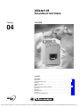
Altistart 48 Panel-Mount Soft Starts
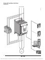
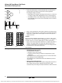
Introduction
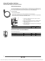
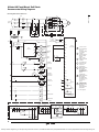
502913.eps
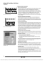
AC Line Supply
Motor
Presentation
2
© 2004 Schneider Electric All Rights Reserved
4/04
Courtesy of Steven Engineering, Inc.-230 Ryan Way, South San Francisco, CA 94080-6370-Main Office: (650) 588-9200-Outside Local Area: (800) 258-9200-www.stevenengineering.com
Altistart 48 Panel-Mount Soft Starts
Introduction
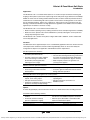
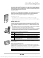
Applications
The ATS48 soft start is a controller with 6 thyristors. It is used for torque-controlled soft starting and
stopping of three-phase asynchronous squirrel cage motors with power ranges between 3 and 1200 hp.
ATS48 soft starts offer soft starting and deceleration functions, machine and motor protection functions,
and functions for communicating with control systems. These functions are designed for use in state-ofthe-art centrifugal machines, pumps, fans, compressors, and conveyors in the construction, food and
beverage, and chemical industries. The high-performance algorithms of the ATS48 soft start contribute
significantly to its robustness and ease of setup.
The ATS48 soft start is a cost-effective solution which can:
• Reduce machine operating costs by reducing mechanical stress and improving machine availability
• Reduce the stress placed on the electrical distribution system by reducing line current peaks and
voltage drops during motor starts
The ATS48 soft start is rated for three-phase voltages 208 to 690 V, 50/60 Hz, and for standard and
severe duty applications.
Functions
The ATS48 soft start is supplied ready for use in a standard duty application with Class 10 motor thermal
overload protection. All devices include a built-in keypad display which can be used to modify the
configuration to adapt it to the application and individual customer requirements.
Soft Start performance functions:
• Exclusive torque control system (TCS)
patented by Schneider Electric
• Constant control of the torque supplied
to the motor during acceleration and
deceleration periods (significantly
reducing pressure surges)
• Adjustments for ramp and the starting torque
• The soft start can be bypassed using a contactor at
the end of the starting period while maintaining
electronic overload protection (bypass function)
• Wider frequency tolerance for generator set
(source) power supplies
Machine and motor protection functions:
• Built-in motor thermal overload protection
• Monitoring of the starting time
• Processing of information from PTC
thermal probes
• Protection against underloads and overcurrents
during continuous operation
Extended I/O functions for integration into control systems:
• 4 logic inputs, 2 logic outputs, 3 relay
• Display of electrical values, running conditions, and
outputs, and 1 analog output
operating time
• Pull-apart terminal connectors
• RS-485 serial link for connection to a
®
• Function for configuring a second set of motor Modbus system
parameters and easy-to-adapt settings
Options
A remote keypad display can be mounted on the door of a wall-mounted or floor-standing enclosure.
PowerSuite advanced dialog solutions:
• PowerSuite Pocket PC with PPC type
terminal.
• A range of wiring accessories for connecting the soft
start to PLCs via a Modbus® Systems connection.
• PowerSuite software workshop.
(Version 1.30, build 5 or higher)
• Ethernet, Fipio®, DeviceNet™ and Profibus® DP
network communication options
Characteristics: pages 4 to 7
Dimensions: pages 16 to 17
Wiring Diagrams: pages 20 to 23
3
4/04
© 2004 Schneider Electric All Rights Reserved
Courtesy of Steven Engineering, Inc.-230 Ryan Way, South San Francisco, CA 94080-6370-Main Office: (650) 588-9200-Outside Local Area: (800) 258-9200-www.stevenengineering.com
Altistart 48 Panel-Mount Soft Starts
Technical Characteristics
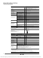
Technical Characteristics
Environment
The ATS48 soft starts have been developed and performance tested in
accordance with international standards, in particular with the starter
product standard EN/IEC 60947-4-2.
Conformity to standards
e marking
CE marking in accordance with the harmonized standard
EN/IEC 60947-4-2.
UL, CSA
DNV, C-Tick, Ghost, CCIB
Product approvals
Pollution degree
Soft starts ATS48D17Y to 48C11Y
IP 20 (IP 00 in the absence of connections)
Soft starts ATS48C14Y to 48M12Y (1)
IP 00
Vibration resistance
Conforming to IEC 60068-2-6
1.5 mm from 2 to 13 Hz
1 gn from 13 to 200 Hz
Shock resistance
Conforming to IEC 60068-2-27
Soft start noise level (2)
Fans
Ambient temperature
around the unit
Maximum relative humidity
15 g for 11 ms
Soft starts ATS48D32Y to D47Y
dBA
52
Soft starts ATS48D62Y to C11Y
dBA
58
Soft starts ATS48C14Y to C17Y
dBA
50
Soft starts ATS48C21Y to C32Y
dBA
54
Soft starts ATS48C41Y to C66Y
dBA
55
Soft starts ATS48C79Y to M12Y
dBA
60
Soft starts ATS48D17Y and D22Y
Natural convection
Soft starts ATS48D32Y to M12Y
Forced convection. The fans are activated automatically when a
temperature threshold is reached. For flow rate, see page 19.
Operation
14 to 104 °F (-10 to 40 °C) without derating
Up to 140 °F (60 °C), derate the current by 2% for each °C above 40 °C
(104 °F)
14 to 122 °F (-10 to 50 °C) with user supplied shorting/bypass contactor
Storage, conforming to
IEC 60947-4-2
-13 to 158 °F (- 25 to 70 °C)
Conforming to IEC 60068-2-3
95% without condensation or dripping water
Maximum ambient pollution Conforming to IEC 60664-1
Level 3
3300 ft (1000 m) without derating. Above this, derate the nominal current
ft (m) of the soft start by 2.2% for each additional 330 ft (100 m) to a maximum
of 6600 ft (2000 m).
510140.eps
Maximum operating altitude
Operating position
Maximum permanent angle in relation to the
normal vertical mounting position
Electrical characteristics
Operating category
Conforming to IEC 60947-4-2
Three-phase supply voltage
Soft starts ATS48pppY (3)
Frequency
AC-53a
V
208 - 15% to 690 + 10%
Hz
50/60 ± 5% (automatic)
50 or 60 ± 20% (must be set)
17 to 1200
Nominal soft start current
Soft starts ATS48pppY
A
SCRs
Soft starts ATS48pppY
PIV
1800
Motor power
Soft starts ATS48pppY
kW
HP
3 to 900
2 to 1200
Voltage indicated on the
motor nameplate
Soft starts ATS48pppY
V
208 to 690
Soft start control circuit
supply voltage
Soft starts ATS48pppY
V
110 - 15% to 230 + 10%, 50/60 Hz
Soft starts ATS48D17Y to C17Y
W
30
Soft starts ATS48C21Y to C32Y
W
50
Soft starts ATS48C41Y to M12Y
W
80
Maximum control circuit
consumption
(with fans operating)
Relay output
(2 configurable outputs)
(1)
(2)
(3)
3 relay outputs (R1, R2, R3), normally open contacts 1 N.O.
Minimum switching capacity: 10 mA for 6 Vdc.
Maximum switching capacity on inductive load: 1.8 A for 230 Vac
and 30 Vdc (power factor= 0.5 and L/R=20 ms). Maximum nominal operating voltage is 400 Vac.
Factory setting: R1 assigned as the fault relay (configurable)
R2 assigned as the end of starting relay to control the soft start bypass relay
R3 assigned as motor powered (configurable)
Protective covers can be fitted to the power terminals of ATS48C14Y to C32Y soft starts. ATS48C41Y to 48M12Y soft starts have protection on the
front panel and on the sides.
Soft starts located 3 ft. (1 m) away. The noise levels may change depending on the characteristics of the fans.
Throughout this catalog, the symbol “•” designates a portion of the catalog number that varies with controller rating.
Technical Characteristics
Characteristics: pages 4 to 7
Dimensions: pages 16 to 17
Wiring Diagrams: pages 20 to 23
4
© 2004 Schneider Electric All Rights Reserved
4/04
Courtesy of Steven Engineering, Inc.-230 Ryan Way, South San Francisco, CA 94080-6370-Main Office: (650) 588-9200-Outside Local Area: (800) 258-9200-www.stevenengineering.com
Altistart 48 Panel-Mount Soft Starts
Technical Characteristics
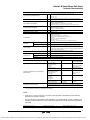
Electrical characteristics (continued)
Logic inputs LI (2 configurable inputs)
4 logic inputs: Stop, Run, LI3, LI4; Impedance: 4.3 kΩ, isolated
+ 24 V input (maximum 30 V) I max. 8 mA
State 0 if V < 5 V
State 1 if V > 11 V
Internal source available
One 24 V output, isolated and protected against short-circuits and overloads.
Accuracy ± 25%. Max. current 200 mA.
Logic outputs LO (configurable)
2 logic outputs LO1 and LO2 with 0 V common, compatible with level 1 PLC,
according to standard IEC 65A-68.
+ 24 V input (minimum: +12 V, maximum: + 30 V) to LO+
Maximum LO output current: 200 mA if external 24 V power supply is used
Analog output AO (configurable)
Current output 0-20 mA or 4-20 mA
Maximum load impedance: 500 Ω
Accuracy ± 5% of the maximum value
Input for PTC probe
Total resistance of probe circuit 750 Ω at 25 °C (77 °F), according to IEC 60 738-A
Maximum I/O connection capacity
12 AWG (2.5 mm2)
Communication
RS-485 multidrop serial link integrated in the starter, for Modbus® Systems,
with RJ45 type connector
Transmission speed 4800, 9600 or 19200 bps
Maximum number of ATS48 soft starts connected: 18
Other uses:
- connection to a remote keypad display or
- connection to a PC or
- connection to other buses and networks via communication options.
Protection
Thermal
Built-in, starter and motor (calculated and/or thermal protection with PTC probes)
Line protection
Phase failure, indicated by output relay
Current settings
The nominal motor current, In, can be adjusted from 0.4 to 1.3 times the starter
nominal current.
Adjustment of the maximum starting current from 1.5 to 7 times the motor In, limited to
5 times the starter nominal current.
Starting mode
By torque control with starter current limited to 5 In maximum.
Factory setting: 4 In for standard operation on 15 s torque ramp
Stopping mode
Freewheel stop
Freewheel stop (factory setting)
Controlled stop on torque ramp
Programmable between 0.5 and 60 s (for pump applications)
Braked stop
Controlled dynamically by the flux
Electromagnetic compatibility EMC (1)
Summary of immunity tests carried out with the
ATS48 soft start
Standards
Test levels
Examples
(sources of interference)
IEC 61000-4-2 level 3
Electrostatic discharge:
- by contact
- in the air
6 kV
8 kV
Contact off an electrically
charged individual
IEC 61000-4-3 level 3
Radiated electromagnetic fields
10 V/m
Equipment transmitting
radio frequencies
IEC 61000-4-4 level 4
Rapid electrical transients:
- power supply cables
- control cables
4 kV
2 kV
Opening/closing of a
contactor
IEC 61000-4-5 level 3
Shock wave:
- phase/phase
- phase/ground
1 kV
2 kV
-
IEC 61000-4-12 level 3
Damped oscillating waves
1 kV - 1 M Hz
Oscillating circuit on the
line supply
According to IEC 60947-4-2, class A, on all starters
Radiated and conducted emissions
(1)
According to IEC 60947-4-2, class B, on starters up to 170 A: ATS48D17p to 48C17p.
Must be bypassed at the end of starting
The soft starts conform to IEC 60947-4-2 (EMC). This standard ensures a level of immunity for products and a level of emitted interference. In steady
state, the interference emitted is below that required by the standard.
NOTE:
• Power factor correction capacitors can only be used upstream of the ATS48 soft start and only
powered up at the end of starting.
• The soft start must be grounded to meet regulations concerning leakage currents (≤ 30 mA). If the
installation involves several soft starts on the same supply line, each soft start must be grounded
separately.
Characteristics: pages 4 to 7
Dimensions: pages 16 to 17
Wiring Diagrams: pages 20 to 23
Technical Characteristics
5
4/04
© 2004 Schneider Electric All Rights Reserved
Courtesy of Steven Engineering, Inc.-230 Ryan Way, South San Francisco, CA 94080-6370-Main Office: (650) 588-9200-Outside Local Area: (800) 258-9200-www.stevenengineering.com
Altistart 48 Panel-Mount Soft Starts
Technical Characteristics
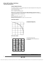
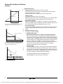
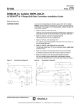
TORQUE CHARACTERISTICS
In the following diagrams, the curves indicate changes in the torque that depend on the starting current
of a three-phase asynchronous motor.
Curve 1: full voltage starting
Curve 2: starting in current limiting mode
Torque curve, Ts1, indicates the total torque range available depending on the limiting current Is1.
Limiting the starting current, Is, to a preset value, Is1, reduces the starting torque, Ts1, to a value which
is almost equal to the square of currents Is1/Is.
Example:
For motor characteristics: Ts = 3 Tn for Is = 6 In,
limit the current to Is1 = 3 In (0.5 Is)
resulting in a starting torque Ts1 = Ts x (0.5)² = 3 Tn x 0.25 = 0.75 Tn
STARTING CURRENT
I/In
5
560169.eps
6
1
1) Full voltage starting current
2) Starting current limited to Is1
4
2
Is1
3
2
1
0
0
0.25
0.5
0.75
1
Motor speed
STARTING TORQUE
560170.eps
T/Tn
6
5
1) Full voltage starting torque
2) Starting torque with current limited to Is1
3) Load torque
4
1
3
2
2
Ts1
1
3
0
0
0.25
Characteristics: pages 4 to 7
0.5
0.75
1
Motor speed
Dimensions: pages 16 to 17
Wiring Diagrams: pages 20 to 23
6
© 2004 Schneider Electric All Rights Reserved
4/04
Courtesy of Steven Engineering, Inc.-230 Ryan Way, South San Francisco, CA 94080-6370-Main Office: (650) 588-9200-Outside Local Area: (800) 258-9200-www.stevenengineering.com
Altistart 48 Panel-Mount Soft Starts
Technical Characteristics
Technical Characteristics
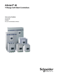
CONVENTIONAL STARTING USING CURRENT LIMITATION OR VOLTAGE RAMP
Motor speed
1
560602 R1.eps
I/In
4
1
3
2
With current limitation Is1, the accelerating torque
applied to the motor is equal to the motor torque
Ts1 minus the resistive torque Tr. The accelerating
torque increases in the starting range as the speed
changes and is at its highest at the end of
acceleration (curve 2). This characteristic means
that the load is taken up very abruptly, which is not
recommended for pump type applications.
Example of speed curve for starting with current
limitation
0.5
2
1) Current applied to the motor (I/In)
2) Motor speed
1
0
t
STARTING WITH THE ATS48 SOFT START
Motor speed
1
560603.eps
I/In
4
3
1
2
0.5
2
Torque control on the ATS48 soft start applies the
torque to the motor during the entire starting phase
if the current required (curve 1) does not exceed
the limiting current. The accelerating torque can be
virtually constant over the entire speed range
(curve 2). It is possible to set the ATS48 soft start
so as to obtain a high torque on starting for a rapid
motor speed rise, while limiting its temperature
rise, and a lower torque at the end of starting for
gradual loading. This control function is ideal for
centrifugal pumps or for machines with high
resistive torque on starting.
Example of speed curve for starting with torque
control
1
1) Current applied to the motor (I/In)
2) Motor speed
0
t
STOPPING WITH THE ATS48 SOFT START
• Freewheel stop: the motor comes to a freewheel stop.
• Decelerated stop: this type of stop is ideal for pumps. It can be used to effectively reduce pressure
surges. Torque control on the ATS48 soft start reduces the effect of hydraulic transients even if the
load increases. This type of control makes adjustment easy.
• Braked stop: this type of stop is suitable for high inertia applications because it reduces the stopping
time of the machine.
Characteristics: pages 4 to 7
Dimensions: pages 16 to 17
Wiring Diagrams: pages 20 to 23
Selection
7
4/04
© 2004 Schneider Electric All Rights Reserved
Courtesy of Steven Engineering, Inc.-230 Ryan Way, South San Francisco, CA 94080-6370-Main Office: (650) 588-9200-Outside Local Area: (800) 258-9200-www.stevenengineering.com
Altistart 48 Panel-Mount Soft Starts
Selection
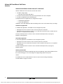
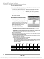
SELECTION CRITERIA FOR AN ATS48 SOFT START UNIT
Select the ATS48 soft start on the basis of three main criteria:
1. AC Mains voltage supply:
— Three-phase AC voltage: 208–690 V
2. The power and the nominal current (motor FLA) indicated on the motor nameplate
3. The type of application and the operating cycle
To simplify selection, the applications are categorized as 2 types:
— Standard duty applications
— Severe duty applications
Standard or severe duty applications define the limiting values of the current and the duty cycle ratings.
Standard Duty Application
In standard duty applications, the ATS48 soft start is designed to provide:
• Starting at 4x In for 23 seconds or at 3x In for 46 seconds from a cold state
• Starting at 3x In for 23 seconds or at 4x In for 12 seconds with a load factor of 50% and with 10 starts
per hour or an equivalent thermal cycling
The motor thermal protection conforms to Class 10 and 20 overload protection (see page 27).
Example: Centrifugal pump
Severe Duty Application
In severe duty applications, the ATS48 soft start is designed to provide:
• Starting at 4x In for 48 seconds or at 3x In for 90 seconds from a cold state
• Starting at 4x In for 25 seconds with a load factor of 50% and with 5 starts per hour or an equivalent
thermal cycling
The motor thermal protection conforms to Class 10 and 20 overload protection (see page 27).
Example: Grinder
Selecting the Soft Start
First consult page 9 to identify the application type. Once the application type has been identified, select
the soft start from pages 12 to 13 according to the supply voltage and the motor power.
Caution:
If the ATS48 soft start is installed inside an enclosure, observe the mounting and derating
recommendations on pages 18 and 19.
Selection Criteria
8
© 2004 Schneider Electric All Rights Reserved
4/04
Courtesy of Steven Engineering, Inc.-230 Ryan Way, South San Francisco, CA 94080-6370-Main Office: (650) 588-9200-Outside Local Area: (800) 258-9200-www.stevenengineering.com
Altistart 48 Panel-Mount Soft Starts
Selection
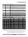
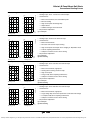
APPLICATION TYPES
Depending on the type of machine, the applications are categorized as standard or severe duty based
on the starting characteristics. Examples are given in the table below.
Starting current Starting time
(% In)
(s)
Type of machine
Application Type Functions performed by the ATS48 Soft Start
Centrifugal pump
Standard
Deceleration (reduction in pressure surges)
Protection against underloads or inversion of the phase 300
rotation direction
5 to 15
Piston pump
Standard
Control of running dry and direction of rotation of the
pump
5 to 10
Fan
Standard
Severe if > 30 s
Detection of overloads caused by clogging or underloads
(motor fan transmission broken)
300
Braking torque on stopping
10 to 40
Cold compressor
Standard
Protection, even for special motors
300
5 to 10
Screw compressor
Standard
Protection against inversion of direction of phase rotation
300
Contact for automatic draining on stopping
3 to 20
Centrifugal compressor
Standard
Severe if > 30 s
Protection against inversion of direction of phase rotation
350
Contact for automatic emptying on stopping
10 to 40
Piston compressor
Standard
Protection against inversion of direction of phase rotation
350
Contact for automatic emptying on stopping
5 to 10
Conveyor, transporter
Standard
Overload control for detecting faults or underload control
300
for detecting breaks
3 to 10
Lifting screw
Standard
Overload control for detecting hard spots or underload
control for detecting breaks
300
3 to 10
Drag lift
Standard
Overload control for detecting jamming or underload
control for detecting breaks
400
2 to 10
Lift
Standard
Overload control for detecting jamming or underload
control for detecting breaks
Constant starting with variable load
350
5 to 10
Circular saw, band saw
Standard
Severe if > 30 s
Braking for fast stop
300
10 to 60
350
Pulper, butchery knife
Severe
Torque control on starting
400
3 to 10
Agitator
Standard
The current display indicates the density of the product
350
5 to 20
Mixer
Standard
The current display indicates the density of the product
350
5 to 10
Grinder
Severe
Braking to limit vibrations during stopping, overload
control to detect jamming
450
5 to 60
Crusher
Severe
Braking to limit vibrations during stopping, overload
control to detect jamming
400
10 to 40
Refiner
Standard
Torque control on starting and stopping
300
5 to 30
Press
Severe
Braking to increase the number of cycles
400
20 to 60
Selection Criteria
9
4/04
© 2004 Schneider Electric All Rights Reserved
Courtesy of Steven Engineering, Inc.-230 Ryan Way, South San Francisco, CA 94080-6370-Main Office: (650) 588-9200-Outside Local Area: (800) 258-9200-www.stevenengineering.com
Altistart 48 Panel-Mount Soft Starts
Selection
SPECIAL USES
Other criteria can influence the selection of the ATS48 soft start:
Shorting/Bypass Contactor
Refer to the recommended wiring diagrams on pages 20 to 23.
The soft start can be bypassed by a contactor at the end of starting (to limit the heat dissipated by the
soft start). The shorting/bypass contactor is controlled by the soft start and the current measurements.
Thermal protection remains active when the soft start is bypassed.
Multi Motors
Motors may be connected in parallel provided that the power limit of the soft start is not exceeded (the
sum of the motor currents must not exceed the nominal current of the soft start selected depending on
the type of application). Individual thermal protection is required for each motor.
Brush Motor
The ATS48 soft start can operate with a bypassed stator resistance motor or with a resistance lug. The
starting torque is modified in accordance with the rotor resistance. If necessary, maintain a low
resistance in order to obtain the required torque to overcome the resistive torque on starting.
A bypassed brush motor has a very low starting torque. A high stator current is required to obtain the
sufficient starting torque.
Oversize the soft start so that the value of the limiting current is 7 times that of the nominal current.
NOTE: Ensure that the starting torque of the motor, equal to 7 times the nominal current, is greater than
the resistive torque.
NOTE: The ATS48 soft start torque control enables excellent soft starting despite the limiting current
being 7 times the nominal current required to start the motor.
2-Speed Motor
The ATS48 soft start can operate with a 2-speed motor. A motor demagnetization period must elapse
before changing from low speed to high speed in order to avoid antiphase between the line supply and
the motor, which would generate very high currents.
Select the soft start using the three main criteria, see page 8.
Long Motor Cable Lengths
Very long motor cables cause voltage drops due to the resistance of the cable. If the voltage drop is
significant, it could affect the current consumption and the available torque. This criteria must be taken
into account when selecting the motor and the soft start.
Miscellaneous Application Precautions
Do not use the ATS48 soft start upstream of loads other than motors (for example transformer and
resistor type loads).
Do not connect power factor correction capacitors to the terminals of a motor controlled by an
ATS48 soft start.
Selection
10
© 2004 Schneider Electric All Rights Reserved
4/04
Courtesy of Steven Engineering, Inc.-230 Ryan Way, South San Francisco, CA 94080-6370-Main Office: (650) 588-9200-Outside Local Area: (800) 258-9200-www.stevenengineering.com
Altistart 48 Panel-Mount Soft Starts
Selection
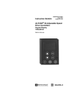
COMMUNICATION
ATS48
ATS48
560752 R1.eps
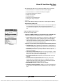
The ATS48 soft start can be connected directly to a Modbus® system using an RJ45 connector. It
communicates over the RS-485 serial link (2-wire) using the Modbus® system’s RTU protocol. The
communication function provides access to the configuration, adjustment, control, and signalling
functions of the soft start.
1. Communication module
2. Modbus® Systems hub LU9GC3
3. Modbus® Systems drop cable VW3A8306Rpp
3
6
1
5. Modbus® Systems splitter cable VW3A8306TFpp
5
4
2
4. Line terminator VW3A8306RC
6. To other buses or networks
3
3
4
The ATS48 soft start can be connected to other buses or networks using the communication modules
and accessories below.
520976.tif
LUFP1
Item
number
Communication modules
Catalog number
Ethernet Bridge
174CEV30020
DeviceNet Gateway
LUFP9
Profibus DP Gateway
LUFP7
FIPIO Gateway
LUFP1
1/3 meter connection cable (RJ45 to RJ45)
VW3A8306R03
1 meter connection cable (RJ45 to RJ45)
VW3A8306R10
3 meter connection cable (RJ45 to RJ45)
VW3A8306R30
1/3 meter splitter cable (RJ45 daisy chain connection)
VW3A8306TF03
1 meter splitter cable (RJ45 daisy chain connection)
VW3A8306TF10
4
RJ45 terminator (2 per package)
VW3A8306RC
2
Modbus hub (Eight RJ45 ports)
LU9GC3
1
3
5
Characteristics: pages 4 to 7
Dimensions: pages 16 to 17
Wiring Diagrams: pages 20 to 23
Selection
11
4/04
© 2004 Schneider Electric All Rights Reserved
Courtesy of Steven Engineering, Inc.-230 Ryan Way, South San Francisco, CA 94080-6370-Main Office: (650) 588-9200-Outside Local Area: (800) 258-9200-www.stevenengineering.com
Altistart 48 Panel-Mount Soft Starts
Selection
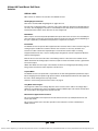
Line Voltage 208 to 690 V, Motor Power in HP
106762.tif
For Standard Duty Applications
106761.tif
ATS48D17Y
Motor
Soft Start 208 to 690 V - 50/60 Hz
Motor power (1)
Soft start
current
rating (2)
Nominal
motor
current (4)
Power
dissipated at
nominal load
Catalog
number
Weight
208 V
230 V
460 V
575 V
HP
HP
HP
HP
A
A
W
3
5
10
15
17
14
59
ATS48D17Y
10.8 (4.9)
5
7.5
15
20
22
21
74
ATS48D22Y
10.8 (4.9)
7.5
10
20
25
32
27
104
ATS48D32Y
10.8 (4.9)
10
–
25
30
38
34
116
ATS48D38Y
10.8 (4.9)
–
15
30
40
47
40
142
ATS48D47Y
10.8 (4.9)
15
20
40
50
62
52
201
ATS48D62Y
18.3 (8.3)
20
25
50
60
75
65
245
ATS48D75Y
18.3 (8.3)
25
30
60
75
88
77
290
ATS48D88Y
18.3 (8.3)
30
40
75
100
110
96
322
ATS48C11Y
18.3 (8.3)
40
50
100
125
140
124
391
ATS48C14Y
27.3 (12.4)
50
60
125
150
170
156
479
ATS48C17Y
27.3 (12.4)
60
75
150
200
210
180
580
ATS48C21Y
40.1 (18.2)
75
100
200
250
250
240
695
ATS48C25Y
40.1 (18.2)
100
125
250
300
320
302
902
ATS48C32Y
40.1 (18.2)
125
150
300
350
410
361
1339
ATS48C41Y
113.3 (51.4)
150
–
350
400
480
414
1386
ATS48C48Y
113.3 (51.4)
–
200
400
500
590
477
1731
ATS48C59Y
113.3 (51.4)
200
250
500
600
660
590
1958
ATS48C66Y
113.3 (51.4)
250
300
600
800
790
720
2537
ATS48C79Y
253.6 (115.0)
350
350
800
1000
1000
954
2865
ATS48M10Y
253.6 (115.0)
400
450
1000
1200
1200
1170
3497
ATS48M12Y
253.6 (115.0)
Catalog
number
Weight
lb (kg)
For Severe Duty Applications
Motor
Soft Start 208 to 690 V - 50/60 Hz
Motor power (1)
Nominal
motor
current (4)
Power
dissipated at
nominal load
208 V
230 V
460 V
575 V
Soft Start
Current
Rating (3)
HP
HP
HP
HP
A
A
W
2
3
7.5
10
12
14
46
ATS48D17Y
10.8 (4.9)
3
5
10
15
17
21
59
ATS48D22Y
10.8 (4.9)
5
7.5
15
20
22
27
74
ATS48D32Y
10.8 (4.9)
7.5
10
20
25
32
34
99
ATS48D38Y
10.8 (4.9)
10
–
25
30
38
40
116
ATS48D47Y
10.8 (4.9)
–
15
30
40
47
52
153
ATS48D62Y
18.3 (8.3)
15
20
40
50
62
65
201
ATS48D75Y
18.3 (8.3)
20
25
50
60
75
77
245
ATS48D88Y
18.3 (8.3)
25
30
60
75
88
96
252
ATS48C11Y
18.3 (8.3)
30
40
75
100
110
124
306
ATS48C14Y
27.3 (12.4)
40
50
100
125
140
156
391
ATS48C17Y
27.3 (12.4)
50
60
125
150
170
180
468
ATS48C21Y
40.1 (18.2)
60
75
150
200
210
240
580
ATS48C25Y
40.1 (18.2)
75
100
200
250
250
302
695
ATS48C32Y
40.1 (18.2)
100
125
250
300
320
361
1017
ATS48C41Y
113.3 (51.4)
125
150
300
350
410
414
1172
ATS48C48Y
113.3 (51.4)
150
–
350
400
480
477
1386
ATS48C59Y
113.3 (51.4)
–
200
400
500
590
590
1731
ATS48C66Y
113.3 (51.4)
200
250
500
600
660
720
2073
ATS48C79Y
253.6 (115.0)
250
300
600
800
790
954
2225
ATS48M10Y
253.6 (115.0)
350
350
800
1000
1000
1170
2865
ATS48M12Y
253.6 (115.0)
106758.tif
ATS48C14Y
ATS48M12Y
(1)
(2)
(3)
(4)
lb (kg)
Value indicated on the motor nameplate.
Corresponds to the soft start’s continuous current rating with overload protection set to Class 10.
Corresponds to the soft start’s continuous current rating with overload protection set to Class 20.
This factory setting corresponds to the value of the nominal current of a standard motor according to NEC, 460 V, Class 10 (standard
application). Adjust the value of parameter In to match the motor’s full load amperage rating.
Characteristics: pages 4 to 7
Dimensions: pages 16 to 17
Wiring Diagrams: pages 20 to 23
Selection
12
© 2004 Schneider Electric All Rights Reserved
4/04
Courtesy of Steven Engineering, Inc.-230 Ryan Way, South San Francisco, CA 94080-6370-Main Office: (650) 588-9200-Outside Local Area: (800) 258-9200-www.stevenengineering.com
Altistart 48 Panel-Mount Soft Starts
Selection
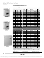
Line Voltage 208 to 690 V, Motor Power in kW
For Standard Duty Applications
Motor
Soft Start 208 to 690 V - 50/60 Hz
Motor power (1)
Soft start
current
rating (2)
Nominal
motor
current (4)
Power
dissipated at
nominal load
Catalog
number
Weight
230 V
400 V
440 V
500 V
525 V
660 V
690 V
kW
kW
kW
kW
kW
kW
kW
A
A
W
4
7.5
7.5
9
9
11
15
17
14
59
ATS48D17Y
10.8 (4.9)
5.5
11
11
11
11
15
18.5
22
21
74
ATS48D22Y
10.8 (4.9)
7.5
15
15
18.5
18.5
22
22
32
27
104
ATS48D32Y
10.8 (4.9)
9
18.5
18.5
22
22
30
30
38
34
116
ATS48D38Y
10.8 (4.9)
11
22
22
30
30
37
37
47
40
142
ATS48D47Y
10.8 (4.9)
15
30
30
37
37
45
45
62
52
201
ATS48D62Y
18.3 (8.3)
18.5
37
37
45
45
55
55
75
65
245
ATS48D75Y
18.3 (8.3)
22
45
45
55
55
75
75
88
77
290
ATS48D88Y
18.3 (8.3)
30
55
55
75
75
90
90
110
96
322
ATS48C11Y
18.3 (8.3)
37
75
75
90
90
110
110
140
124
391
ATS48C14Y
27.3 (12.4)
45
90
90
110
110
132
160
170
156
479
ATS48C17Y
27.3 (12.4)
55
110
110
132
132
160
200
210
180
580
ATS48C21Y
40.1 (18.2)
75
132
132
160
160
220
250
250
240
695
ATS48C25Y
40.1 (18.2)
90
160
160
220
220
250
315
320
302
902
ATS48C32Y
40.1 (18.2)
110
220
220
250
250
355
400
410
361
1339
ATS48C41Y
113.3 (51.4)
132
250
250
315
315
400
500
480
414
1386
ATS48C48Y
113.3 (51.4)
160
315
355
400
400
560
560
590
477
1731
ATS48C59Y
113.3 (51.4)
–
355
400
–
–
630
630
660
590
1958
ATS48C66Y
113.3 (51.4)
220
400
500
500
500
710
710
790
720
2537
ATS48C79Y
253.6 (115.0)
250
500
630
630
630
900
900
1000
954
2865
ATS48M10Y
253.6 (115.0)
355
630
710
800
800
–
–
1200
1170
3497
ATS48M12Y
253.6 (115.0)
Catalog
number
Weight
lb (kg)
For Severe Duty Applications
Motor
Soft Start 208 to 690 V - 50/60 Hz
Motor power (1)
Nominal
motor
current (4)
Power
dissipated at
nominal load
230 V
400 V
440 V
500 V
525 V
660 V
690 V
Soft start
current
rating (3)
kW
kW
kW
kW
kW
kW
kW
A
A
W
3
5.5
5.5
7.5
7.5
9
11
12
14
46
ATS48D17Y
10.8 (4.9)
4
7.5
7.5
9
9
11
15
17
21
59
ATS48D22Y
10.8 (4.9)
5.5
11
11
11
11
15
18.5
22
27
74
ATS48D32Y
10.8 (4.9)
7.5
15
15
18.5
18.5
22
22
32
34
99
ATS48D38Y
10.8 (4.9)
9
18.5
18.5
22
22
30
30
38
40
116
ATS48D47Y
10.8 (4.9)
11
22
22
30
30
37
37
47
52
153
ATS48D62Y
18.3 (8.3)
15
30
30
37
37
45
45
62
65
201
ATS48D75Y
18.3 (8.3)
18.5
37
37
45
45
55
55
75
77
245
ATS48D88Y
18.3 (8.3)
22
45
45
55
55
75
75
88
96
252
ATS48C11Y
18.3 (8.3)
30
55
55
75
75
90
90
110
124
306
ATS48C14Y
27.3 (12.4)
37
75
75
90
90
110
110
140
156
391
ATS48C17Y
27.3 (12.4)
45
90
90
110
110
132
160
170
180
468
ATS48C21Y
40.1 (18.2)
55
110
110
132
132
160
200
210
240
580
ATS48C25Y
40.1 (18.2)
75
132
132
160
160
220
250
250
302
695
ATS48C32Y
40.1 (18.2)
90
160
160
220
220
250
315
320
361
1017
ATS48C41Y
113.3 (51.4)
110
220
220
250
250
355
400
410
414
1172
ATS48C48Y
113.3 (51.4)
132
250
250
315
315
400
500
480
477
1386
ATS48C59Y
113.3 (51.4)
160
315
355
400
400
560
560
590
590
1731
ATS48C66Y
113.3 (51.4)
–
355
400
–
–
630
630
660
720
2073
ATS48C79Y
253.6 (115.0)
220
400
500
500
500
710
710
790
954
2225
ATS48M10Y
253.6 (115.0)
250
500
630
630
630
900
900
1000
1170
2865
ATS48M12Y
253.6 (115.0)
(1)
(2)
(3)
(4)
lb (kg)
Value indicated on the motor nameplate.
Corresponds to the soft start’s continuous current rating with overload protection set to Class 10.
Corresponds to the soft start’s continuous current rating with overload protection set to Class 20.
This factory setting corresponds to the value of the nominal current of a standard motor according to NEC, 460 V, Class 10 (standard application). Adjust the value of parameter In to match
the motor’s full load amperage rating.
Characteristics: pages 4 to 7
Dimensions: pages 16 to 17
Wiring Diagrams: pages 20 to 23
13
4/04
© 2004 Schneider Electric All Rights Reserved
Courtesy of Steven Engineering, Inc.-230 Ryan Way, South San Francisco, CA 94080-6370-Main Office: (650) 588-9200-Outside Local Area: (800) 258-9200-www.stevenengineering.com
Altistart 48 Panel-Mount Soft Starts
Remote Keypad Display and Protective Covers
Remote Terminal/Keypad, Protective Covers, Documentation
106770.tif
REMOTE KEYPAD DISPLAY
The remote keypad display can be mounted on the door of a wall-mounted or floor-standing enclosure.
It has the same signalling display and configuration buttons as the keypad display integrated in the soft
start. A switch to lock access to the menus is located on the back of the keypad display.
The option includes:
• The remote keypad display
• A mounting kit containing a cover, screws and an IP 65 seal on the front panel
VW3G48101
1
510089.eps
• A 9.82 ft. (3 m) connecting cable with a 9-pin SUB-D connector for connecting to the keypad display
and an RJ45 connector for connecting to the ATS48 soft start.
1. Information is displayed in the form of codes or values in
three 7-segment displays
2. Buttons for scrolling through the menus or modifying values
ESC
3
E NT
4
3. ESC: Button for exiting the menus (cannot be used for
validation purposes)
4. ENT: Validation button for entering a menu or confirming the
new value selected
2
Description
Catalog number
Weight lb (kg)
Remote keypad display
VW3G48101
0.44 (0.20)
813095.eps
PROTECTIVE COVERS FOR POWER TERMINALS
To be used with tags closed
For Soft Starts
Number of covers per set
Catalog number
Weight lb (kg)
ATS48C14Y and ATS48C17Y
6 (1)
LA9F702
0.6 (0.25)
ATS48C21Y, ATS48C25Y and ATS48C32Y
6 (1)
LA9F703
0.6 (0.25)
(1)
The soft starts have 9 unprotected power terminals.
LA9F702
14
© 2004 Schneider Electric All Rights Reserved
4/04
Courtesy of Steven Engineering, Inc.-230 Ryan Way, South San Francisco, CA 94080-6370-Main Office: (650) 588-9200-Outside Local Area: (800) 258-9200-www.stevenengineering.com
Altistart 48 Panel-Mount Soft Starts
Powersuite® Advanced Dialog Solutions
PowerSuite Advanced dialog Solutions
The PowerSuite advanced dialog solutions can be used for Telemecanique drives and soft starts. They
enable communication with the product from a Pocket PC, Personal Computer, or a dedicated terminal.
The PowerSuite dialog solutions, with a Pocket PC or PC, enable files to be prepared for uploading to
the drives and the soft starts. The PowerSuite software creates its files ensuring consistency between
the configuration/adjustment functions of the product.
PowerSuite Pocket PC
502945.eps
The Pocket PC can be used during preparation, programming, setup and maintenance. It comprises a
Pocket PC terminal and corresponding connection accessories. The software is integrated into a
Windows CE environment. The software incorporates all the functions of integrated and remote
terminals (drive or soft start configuration and adjustment, control, signalling, etc).
The Pocket PC can be used:
• Alone to prepare and store configuration/adjustment files (integral battery or line supply).
• Connected to the drive or to the soft start for configuration, adjustment or control purposes or to
upload a configuration/adjustment file from the Pocket PC to the product or download a configuration/
adjustment file from the product to the Pocket PC.
PowerSuite Software for PC
510086.eps
The PowerSuite software is used to set up a drive or a soft start from a PC in a Microsoft® Windows
environment. The software incorporates all the functions of integrated and remote terminals (drive or
soft start configuration and adjustment, control, signalling, etc.) in a Windows environment. It can be
used:
• Alone to prepare and store drive or soft start configuration files. The drive or soft start configuration
can be printed out on paper or can be exported to office automation software.
• Connected to the drive or soft start for configuration, adjustment or control purposes, or for uploading
a configuration/adjustment file from the PC to the product or downloading from the product to the PC.
Connection is via a link between the drive or soft start connector and the serial port on the PC.
9
POWERSUITE Products Available from Schneider Electric
Catalog
number
Description
VW3A8104
POWERSUITE commissioning software on CD
PC connection kit. Includes the following to connect a PC to an ATV11, ATV28, ATV58, ATS48, or TeSys U controller:
VW3A8106
1 m (3.28 ft.) cable with RJ45 connectors
RS-232 to RS-485 adapter with RJ45 and DB9 female connectors
VW3A8110
Optional compact flash memory module loaded with POWERSUITE software, for use with JORNADA and iPAQ PPCs
510888.eps
VW3A8111
VW3A11301
RJ45 to DB9 male adapter for use with an ATV58 controller
Cable adapter for use with an ATV11 controller, VW3A11301
Pocket PC connection kit. Includes the following to connect a JORNADA or iPAQ PPC to an ATV11, ATV28, ATV58, ATS48,
or TeSys U controller:
0.5 m (1.64 ft.) cable with RJ45 connectors
RS-232 to RS-485 adapter with RJ45 and DB9 male connectors
RJ45 to DB9 male adapter for use with an ATV58 controller
Cable adapter for use with an ATV11 controller, VW3A11301
RS-485 to TTL cable adapter for use with the ATV11 controller
For more information about PowerSuite software, obtain Data Bulletin 8806DB0001R_ available at
www.us.SquareD.com.
Magelis® Display Unit With Matrix Screen
The Magelis® display unit with matrix screen can be used to monitor, diagnose, and adjust up to 8
ATS48 soft starts in 5 languages (English, French, German, Spanish, Italian). It can display variables in
alphanumeric format with European, Cyrillic, or Asian fonts in 4 sizes, or it can display icons or
background images in black and white, as well as animations in barchart or gauge format. The terminal
has a backlit LCD with 8 lines of 40 characters.
Description
Catalog number
Weight lb (kg)
Magelis® display unit with matrix screen
XBTHM017010A8
1.3 (0.60)
15
4/04
© 2004 Schneider Electric All Rights Reserved
Courtesy of Steven Engineering, Inc.-230 Ryan Way, South San Francisco, CA 94080-6370-Main Office: (650) 588-9200-Outside Local Area: (800) 258-9200-www.stevenengineering.com
Altistart 48 Panel-Mount Soft Starts
Dimensions
11.42
290
M6
7.48
190
=
3.94
=
100 6.3
160
inches
mm
M6
7.48
190
9.25
235
Maximum connection capacity:
Ground connections: 8 AWG (10 mm2)
Power terminals: 8 AWG (16 mm2)
0.39
10
5.9
150 M6
10.63
270
0.26
6.6
4x 7
10.24
260
10.83
275
M6
560172.eps
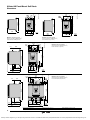
ATS48D62Y to ATS48C11Y
4x 7
560171.eps
ATS48D17Y to ATS48D47Y
inches
mm
Maximum connection capacity:
Ground connections: 4 AWG (16 mm2)
Power terminals: 2/0 (50 mm2)
3/L2
5/L3
Maximum connection capacity:
Ground connections: Busbar (120 mm2)
Power terminals: 2/0 (95 mm2)
0.55
0.04 14
1
13.39
340
12.6
320
1/L1
0.79
20
4x 7
0.4
10
6.26
159
=
160
1.58
40 M6
0.08
2
0.2
5
6.30
=
0.04
1
0.71
18
560173.eps
ATS48C14Y to ATS48C17Y
9x 8
M6
1.5 2.44 2.44
38 62
62 7.87
200
0.2
4.59
0.2 5 6.38 116.5
5 10.43 162
265
inches
mm
9x 12
1/L1
3/L2
5/L3
4x 9
0.08
2
M10
Maximum connection capacity:
Ground connections: Busbar (120 mm2)
Power terminals: Busbar (240 mm2)
0.39
10
5.37
136.5
=
9.84
250
2.6
66
0.2
5.37
5 7.74 136.5
0.2
5 10.43 196.5
265
2.76
70
M10
3.54
90
0.79
3.5420
90 12.6
320
Characteristics: pages 4 to 7
0.04
1
0.71
18
14.96
380
0.2
5
=
13.78
350
1.38
35
560174.eps
ATS48C21Y to ATS48C32Y
inches
mm
Dimensions: pages 16 to 17
Wiring Diagrams: pages 20 to 23
16
© 2004 Schneider Electric All Rights Reserved
4/04
Courtesy of Steven Engineering, Inc.-230 Ryan Way, South San Francisco, CA 94080-6370-Main Office: (650) 588-9200-Outside Local Area: (800) 258-9200-www.stevenengineering.com
Altistart 48 Panel-Mount Soft Starts
Dimensions
Dimensions
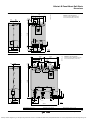
ATS48C41Y to C66Y
4.72
120
4x 9
2.72127 M10
69 1L1
3L2
0.8
20
6.5
165
=
Maximum connection capacity:
Ground connections: Busbar (240 mm2)
Power terminals: Busbar (2 x 240 mm2)
5L3
24.02
610
26.38
670
0.2
5
0.2
5
11.8
4.53 300 4.53
115
5 115
560175.eps
=
0.2
5
0.2
5 11.8
300
0.06
1.5
1.57
40
58
6.5
8.5 165
216
0.01
M10
1.98 0.25
50.25
4.53
115
1.57
40
4.53
115 15.75
400
inches
mm
ATS48C79Y to M12Y
0.8
20
6.69
170
1.02
26 8.25
209.5
18x 14
26 8.8
223.5
M10
Maximum connection capacity:
Ground connections: Busbar (2 x 240 mm2)
Power terminals: Busbar (4 x 240 mm2)
560176.eps
6.46129
164
6x 9
=
13.78
350
1.02
26
.08
2
0.2
5
13.78
10.12 350
5.08 2571.02
1.02
26
=
7.09
180
8.98
1.02 228
26
1.02
26
5
8.03
1.02 204
26
1.02
0.95 26
1.02 24
26
33.46
850
35.04
890
6.1
155
0.2 4.59
116.5
0.2 57.74
196.5
5 12.4
315
2.36
3.74 60
95 7.4
188
Characteristics: pages 4 to 7
M10
2.36
60
30.31
770
Dimensions: pages 16 to 17
inches
mm
Wiring Diagrams: pages 20 to 23
17
4/04
© 2004 Schneider Electric All Rights Reserved
Courtesy of Steven Engineering, Inc.-230 Ryan Way, South San Francisco, CA 94080-6370-Main Office: (650) 588-9200-Outside Local Area: (800) 258-9200-www.stevenengineering.com
Altistart 48 Panel-Mount Soft Starts
Mounting
Mounting
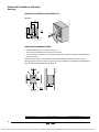
MOUNTING THE REMOTE KEYPAD DISPLAY
VW3G48101
560517.eps
2.05
52
0.95
24
2.2
55.6
3.13
79.6
inches
mm
4xØ3.5
A
Ø36
MOUNTING RECOMMENDATIONS
• Install the ATS48 soft start vertically, within ± 10°.
• Do not place the ATS48 soft start near sources of heat.
• Leave sufficient free space to ensure that the air required for cooling can circulate from the bottom to
the top of the unit.
4
100
560179.eps
NOTE: The IP 00 version of the ATS48 soft start must be fitted with a protective cover to protect
personnel against electrical contact. Protective covers are available for the ATS48C14Y to ATS48C32Y.
They should be ordered separately. See page 14.
2
50
0.4
10
4
100
2
50
inches
mm
Characteristics: pages 4 to 7
Dimensions: pages 16 to 17
Wiring Diagrams: pages 20 to 23
Mounting
18
© 2004 Schneider Electric All Rights Reserved
4/04
Courtesy of Steven Engineering, Inc.-230 Ryan Way, South San Francisco, CA 94080-6370-Main Office: (650) 588-9200-Outside Local Area: (800) 258-9200-www.stevenengineering.com
Altistart 48 Panel-Mount Soft Starts
Mounting
803665.eps
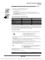
MOUNTING IN A METAL WALL-MOUNTED OR FLOOR-STANDING ENCLOSURE
WITH DEGREE OF PROTECTION TYPE 1 (IP 23) OR TYPE 12 (IP 54)
• To ensure proper air circulation in the soft start:
— Fit ventilation grilles
803666.eps
(104 ˚F)
(104 ˚F)
• Observe the mounting recommendations on page 18.
— Ensure that there is sufficient ventilation. If not, install forced ventilation with a filter.
The openings and/or fans must provide a flow rate at least equal to that of the soft start fans
(see the table below)
• Use special filters with Type 12 (IP 54) protection.
Fan Flow Rate Depending On The Soft Start Rating
ATS48 Soft Start
Flow rate CFM
Flow rate m3/hour
ATS48D32Y and D38Y
24
14
ATS48D47Y
48
28
ATS48D62Y to C11Y
146
86
ATS48C14Y and C17Y
235
138
ATS48C21Y to C32Y
476
280
ATS48C41Y to C66Y
1020
600
ATS48C29Y to M12Y
2040
1200
For non-ventilated ATS48 soft starts (ATS48D17Y and 48D22Y) in metal wall-mounted or floor-standing
enclosures with Type 12 (IP 54) degree of protection, install no more than 2" (50 mm) below the soft
start to circulate the air inside the enclosure in order to avoid hot spots.
Calculating Enclosure Size
The maximum allowable thermal resistance of the enclosure, Rth (°C/W), is calculated as follows:
Rth =
θ – θe
P
θ = maximum temperature inside enclosure in °C
θe = maximum external temperature in °C
P = total power dissipated in the enclosure in W
• The soft start/motor combinations on pages 12 and 13 can be used in ambient temperatures
≤ 40 °C (104 °F).
• For temperatures between 40 °C and 60 °C (104 °F and 140 °F), derate the maximum permanent
current of the soft start by 2% for every degree above 40 °C (104 °F).
• For the power dissipated by the soft starts at rated load: see pages 12 and 13.
• If the starts are infrequent, use a shorting/bypass contactor with the ATS48 soft start at the end of
starting to minimize heat dissipation.
Calculate minimum useful heat exchange surface area requirement, S (in2):
S=K
Rth
Rth = thermal resistance of the enclosure (calculated previously)
K = thermal resistance per square inch of the enclosure
K = 186 with enclosure fan
K = 233 without enclosure fan
Compare the effective heat exchange surface area to the proposed wall mounted enclosure, S (in2)
which should be less than:
S = (Front area) + (Top area) + 2 (Side area)
Characteristics: pages 4 to 7
Dimensions: pages 16 to 17
Wiring Diagrams: pages 20 to 23
19
4/04
© 2004 Schneider Electric All Rights Reserved
Courtesy of Steven Engineering, Inc.-230 Ryan Way, South San Francisco, CA 94080-6370-Main Office: (650) 588-9200-Outside Local Area: (800) 258-9200-www.stevenengineering.com
Altistart 48 Panel-Mount Soft Starts
Recommended Wiring Diagrams
Recommended Wiring Diagrams
Circuit Breaker *
w/Shunt Trip *
wiring 2B final.eps
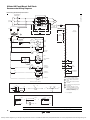
Nonreversing with Shunt Trip Fault Isolation
A2
1/L1
2/T1
3/L2
4/T2
A
B2
AC LINE
SUPPLY
B
M
C2
6/T3
5/L3
C
FU4
*
FU3
2
CL1
{
SC
*
FU2
*
TO CONTROL
POWER
TRANSFORMER
CL2
*
SC
STOP
ATS48
SOFT START
SC
*
T1
GND
RUN
1
SEE
DETAIL B
LI3
120V
LI4
*
CL2
FU4
FU1
MOTOR
THERMAL SW
FAULT
(R1C)
(R1A)
*
+24V
*
FAULT
RELAY
FR
3
4
LO+
TS
LO1
FR
TRIP
RELAY
*
TR
LO2
TS
AO1
TR
CB SHUNT
TRIP COIL
*
ST
COM
(2 SEC)
G
SEE
DETAIL A
(A)
*
PTC2
5
RUN COMMAND
*
*
PTC1
RUN
RCR
RELAY
R1A
(B)
(C)
FAULT
TS
R1C
RCR
END
START UP
(R2C)
(R2A)
R2A
SCA
SHORTING
CONTACTOR
*
R2C
END
START UP
PILOT RELAY
3
R3A
TS
SCA
2
SC
SHORTING
CONTACTOR
*
R3C
PROGRAMMABLE
N.O. CONTACT
TS
R
*
DETAIL A (120 V RCR CONTROL)
OFF
HAND
OFF
AUTO
ON
STOP
START
(A)
OR
(A)
2
For shorting contactor operation,
add SC with associated control
circuit.
Relay contact located on ATS48
controller.
3-WIRE CONTROL
(B)
REMOTE
START
(A)
Connect control power transformer
for 120 V secondary voltage.
3
2-WIRE CONTROL W / O AUTO
2-WIRE CONTROL W / AUTO
1
POWER ON
(B)
4
Located at motor. Jumper if switch
not present.
5
Use RCR relay logic for 120 V
control of the ATS48. For 24 Vdc
control, omit the RCR relay logic
and wire controls directly to the
ATS48 (see DETAIL B).
*=
User supplied
(B)
OR
(C)
DETAIL B
120 V RCR CONTROL
2-WIRE 24 VDC CONTROL
STOP
STOP
RUN
RUN
3-WIRE 24 VDC CONTROL
STOP
STOP
RUN
RCR
OR
OFF
OR
RUN
ON
+24V
+24V
Characteristics: pages 4 to 7
+24V
Dimensions: pages 16 to 17
Wiring Diagrams: pages 20 to 23
20
© 2004 Schneider Electric All Rights Reserved
4/04
Courtesy of Steven Engineering, Inc.-230 Ryan Way, South San Francisco, CA 94080-6370-Main Office: (650) 588-9200-Outside Local Area: (800) 258-9200-www.stevenengineering.com
Altistart 48 Panel-Mount Soft Starts
Recommended Wiring Diagrams
Recommended Wiring Diagrams
SW
*
wiring 1C final.eps
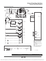
Nonreversing with Isolation Contactor
A2
*
FU5
*
A
IC
1/L1
2/T1
IC
3/L2
4/T2
B2
FU6
AC LINE
SUPPLY
B
M
C2
FU7
6/T3
5/L3
IC
C
FU4
CL1
{
SC
*
*
FU2
*
TO CONTROL
POWER
TRANSFORMER
GND
CL2
FU3
2
SC
STOP
ATS48
SOFT START
SC
*
T1
RUN
1
LI3
120V
FU1
*
FU4
MOTOR
THERMAL SW
LI4
RCR
CL2
+24V
*
SEE
DETAIL A
(A)
4
*
RUN COMMAND
RELAY
*
RCR
LO+
(B)
(C)
TS
LO1
RCR
LO2
FAULT
(R1C)
(R1A)
FAULT
RELAY
*
FR
AO1
3
TS
FR
RCR
IC
5
COM
ISOLATION
*
PTC1
CONTACTOR
PTC2
TS
END
START UP
(R2C)
(R2A)
R1A
SCA
SHORTING
CONTACTOR
*
3
FAULT
R1C
PILOT RELAY
TS
R2A
SCA
SC
*
2
SHORTING
CONTACTOR
R2C
TS
R
END
START UP
R3A
*
POWER ON
*
FAULT
*
RUN
R3C
PROGRAMMABLE
N.O. CONTACT
FR
W
IC
G
1
Connect control power transformer
for 120 V secondary voltage.
2
For shorting contactor operation
add SC with associated control
wiring.
Relay contact located on ATS48
controller.
3
4
Located at motor. Jumper if switch
not present.
5
Set RCR time slightly longer than
expected deceleration time from
rated speed to zero speed.
DETAIL A
2-WIRE CONTROL W / O AUTO
2-WIRE CONTROL W / AUTO
OFF
HAND
OFF
AUTO
3-WIRE CONTROL
ON
STOP
(B)
START
(A)
(A)
REMOTE
START
OR
(A)
(B)
(B)
OR
(C)
Characteristics: pages 4 to 7
Dimensions: pages 16 to 17
*=
User supplied
Wiring Diagrams: pages 20 to 23
21
4/04
© 2004 Schneider Electric All Rights Reserved
Courtesy of Steven Engineering, Inc.-230 Ryan Way, South San Francisco, CA 94080-6370-Main Office: (650) 588-9200-Outside Local Area: (800) 258-9200-www.stevenengineering.com
Altistart 48 Panel-Mount Soft Starts
Recommended Wiring Diagrams
Recommended Wiring Diagrams
SW
*
wiring 3C final.eps
Reversing with Isolation Contactors
A2
FU5
*
*
A
IC1
1/L1
2/T1
IC1
3/L2
4/T2
B2
FU6
AC LINE
SUPPLY
B
M
C2
FU7
IC1
C
5/L3
*
IC2
FU2
*
FU3
SC
*
*
T1
6/T3
2
IC2
SC
IC2
SC
1
FU4
120V
FU1
*
FU4
MOTOR
THERMAL SW
(B)
STOP
*
RUN FWD
RELAY
RFR
(C)
SEE
DETAIL A
*
(D)
RFR
FAULT
1
Connect control
power transformer
for 120 V
secondary voltage.
2
For shorting
contactor
operation, add SC
with associated
circuitry.
3
Relay contact
located on ATS48
controller.
4
Located at motor.
Jumper if switch
not present.
TS
RFR
LI3
RUN REV
RELAY
*
(R1A)
ATS48
SOFT START
RUN
RRR
(E)
GND
CL2
RRR
(A)
4
CL1
{
CL2
*
*
TO CONTROL
POWER
TRANSFORMER
LI4
RRR
TS
(R1C)
FR
RRR
IC1
RFR
IC2
+24V
FAULT
*
RELAY
3
LO+
TS
RFR
FR
IC2
5
IC1
LO1
FORWARD
CONTACTOR
*
LO2
TS
RRR
6
IC1
IC2
5
AO1
REVERSING
CONTACTOR
*
COM
TS
END
START UP
(R2C)
(R2A)
*
SCA
3
SHORTING
CONTACTOR
PTC1
PILOT RELAY
PTC2
6
TS
SCA
R1A
2
SC
SHORTING
*
CONTACTOR
R1C
FAULT
TS
7
R2A
*
POWER ON
R
R2C
END
START UP
FR
*
FAULT
*
RUN FORWARD
*
RUN REVERSE
W
R3A
*=
Set RFR time
slightly longer than
the expected
deceleration time
from rated forward
speed to zero
speed.
Set RRR time
slightly longer than
the expected
deceleration time
from rated reverse
speed to zero
speed.
Remove these
contacts to inhibit
direction reversal
without first
depressing STOP
push button.
User supplied
R3C
IC1
G
PROGRAMMABLE
N.O. CONTACT
IC2
A
DETAIL A
2-WIRE CONTROL W / AUTO START AUTO DIRECTION
HAND
(A)
FWD
AUTO
F
REV
FWD
(B)
OFF
REV
STOP
(B)
(A)
(A)
R
2-WIRE CONTROL W / AUTO START MANUAL DIRECTION
3-WIRE CONTROL
2-WIRE CONTROL W / O AUTO
OFF
RUN
REV
7
(D)
REMOTE
START
R
F
RUN
FWD
OFF
HAND
(B)
AUTO
FWD
REV
(B)
(A)
(C)
(D)
REMOTE
START
(D)
7
(D)
(E)
22
© 2004 Schneider Electric All Rights Reserved
4/04
Courtesy of Steven Engineering, Inc.-230 Ryan Way, South San Francisco, CA 94080-6370-Main Office: (650) 588-9200-Outside Local Area: (800) 258-9200-www.stevenengineering.com
Altistart 48 Panel-Mount Soft Starts
Recommended Component Lists
Recommended Wiring Diagrams
Description of Logic for Recommended Wiring Diagrams
Item
Name
Description
IC1
IC1A
Isolation Contactor (Fwd)
The isolation contactor logic closes IC1 upon a start command and opens IC1 after the stop is complete. The RCR (or RFR and
RRR for reversing) are timed contacts that must have a time delay greater than the deceleration ramp time or the braking time.
When a coast stop is selected, the time delay must be set for a time that will allow a complete decay of the motor residual voltage.
The isolation contactor will open immediately upon a fault. The pilot relay (IC1A) is required when the IC1 contactor coil exceeds
the ATS48 relay output ratings.
IC2
IC2A
Isolation Contactor (Rev)
Used for reversing applications only, the IC2 must be mechanically interlocked to IC1. A reversing contactor may be used for the
combination of IC1 and IC2. In general, the operation of IC2 is identical to IC1. The pilot relay (IC1A) is required when the IC1
contactor coil exceeds the ATS48 relay output ratings
SC
SCA
Shorting Contactor & Pilot Relay
The shorting contactor is used to reduce the heat dissipated by the soft start when the motor is operating at full speed and voltage.
The soft start provides proper sequencing of this contactor by the “end-start-up” relay. When the start is completed, the shorting
contactor will be commanded to close. The soft start will continue to monitor the motor thermal state and provide motor overload
protection. Upon a stop command, the SC contactor will open, transferring the motor current to the ATS48 soft start to allow for
controlled deceleration if desired. The pilot relay (SCA) is required when the SC contactor coil exceeds the ATS48 relay output
ratings.
TS
Transient Suppressors
Transient suppression of all relay and contactor coils (except ST) is recommended to minimize the possibility of electrical
interference with the soft start electronics and to increase relay contact life.
RCR
Run Command Relay
Used in shunt trip fault isolation installations only if 120 V control of the ATS48 soft start is required.
Used in non-reversing installations with a isolation contactor for proper sequencing of contactor logic. When energized, RCR
initiates the start sequence. When de-energized, stopping is initiated. Operator controls can be either on/off selector switch, HOA
selector switch or start/stop push buttons. RCR remains energized during a fault. Once the fault condition has been cleared, RCR
must be de-energized by a “stop” command then re-energized to restart the soft start.
RFR
Run Forward Relay
Used for reversing applications only, this coil duplicates the functionality of RCR for the forward direction and is interlocked with the
RFR relay.
RRR
Run Reverse Relay
Used for reversing applications only, this coil duplicates the functionality of RCR for the reverse direction and is interlocked with the
RRR relay.
ST
Shunt Trip Coil
This coil is attached to the shunt trip coil on the disconnect and will energize 2 seconds after a soft start fault by the TR timer contact.
The time delay is to prevent nuisance tripping of the circuit breaker during soft start power-up or during line undervoltage conditions.
TR
Trip Relay
Used in shunt trip circuit breaker logic only; coil energized upon a soft start fault.
FR
Fault Relay
The fault relay is energized during normal operation and deenergizes if the soft start fault contacts open or if the motor thermal
switch (if supplied) opens. FR also provides additional contacts for the soft start fault output.
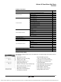
Suggested Components for Standard Duty Applications
Induction Motor
ATS48 Soft Start
Rated hp (1)
ATS48 Soft Start
FU4
Device Rated Current
ATS Control
Class CC 600 V
Time Delay
208 V
230 V
460 V
575 V
Model
@ 40 °C (104 °F)(2)
Power Burden (W)
@115 V
3
5
10
15
ATS48D17Y
17
25
0.5 A
5
7.5
15
20
ATS48D22Y
22
25
0.5 A
7.5
10
20
25
ATS48D32Y
32
30
0.6 A
10
—
25
30
ATS48D38Y
38
30
0.6 A
—
15
30
40
ATS48D47Y
47
30
0.6 A
15
20
40
50
ATS48D62Y
62
30
0.6 A
20
25
50
60
ATS48D75Y
75
30
0.6 A
25
30
60
75
ATS48D88Y
88
30
0.6 A
30
40
75
100
ATS48C11Y
110
30
0.6 A
40
50
100
125
ATS48C14Y
145
30
0.6 A
50
60
125
150
ATS48C17Y
170
30
0.6 A
60
75
150
200
ATS48C21Y
210
50
1A
75
100
200
250
ATS48C25Y
250
50
1A
100
125
250
300
ATS48C32Y
320
50
1A
125
150
300
350
ATS48C41Y
410
80
1.5 A
150
—
350
400
ATS48C48Y
480
80
1.5 A
—
200
400
500
ATS48C59Y
590
80
1.5 A
200
250
500
600
ATS48C66Y
660
80
1.5 A
250
300
600
800
ATS48C79Y
790
80
1.5 A
350
350
800
1000
ATS48M10Y
1000
80
1.5 A
400
450
1000
1200
ATS48M12Y
1200
80
1.5 A
(1)
(2)
Motor full load currents through 500 hp @ 460/575 V, 250 hp @ 230 V, and 200 hp @ 208 V are taken from the National Electric Code (NFPA 70-2002, Table 430.150). Above these ratings,
motor full load currents are calculated based upon 1.2 A/hp for 460 V and 2.4 A/hp for 230 V. Motors listed are for standard duty applications. For severe duty applications, select the next
larger soft start size.
The ambient temperature indicated in the table represents the temperature of the air surrounding the ATS48 soft start. Any additional temperature factors associated with the enclosure
system or actual installation ambient temperature must be considered when determining the actual rated current (ICL) of the soft start. For operating ambient above 40 °C (104 °F) without
a shorting/bypass contactor and 50 °C (122 °F) with a shorting/bypass contactor but not exceeding 60 °C (140 °F) , the rated current (ICL) of the soft start must be de-rated by 2% per °C.
NOTE: To select control operators (push buttons, pilot lamps, and selector switches), control power
transformers, and wire management devices (control and power terminal strips, wire terminations)
indicated on the recommended wiring diagram configurations, visit www.us.squared.com.
Recommended Component Lists
23
4/04
© 2004 Schneider Electric All Rights Reserved
Courtesy of Steven Engineering, Inc.-230 Ryan Way, South San Francisco, CA 94080-6370-Main Office: (650) 588-9200-Outside Local Area: (800) 258-9200-www.stevenengineering.com
Altistart 48 Panel-Mount Soft Starts
Recommended Component Lists
Additional Suggested Components for Standard Duty Applications
ATS48 Soft
Start
Contactors (1), (2), (3)
Disconnect (4)
IC1
IC2
ATS48 Model
Isolation
Contactor
Reversing
Contactor (5)
Mechanical
Interlock
Shorting
Power Fuses
Contactor (AC1) Class/Rating
SC
Fusible Disconnect
Circuit Breaker
Fuse Block
D17Y
LC1D09
LC1D09
(8)
LC1D09
J / 25
D22Y
LC1D18
LC1D18
(8)
LC1D18
J / 30
D32Y
LC1D25
LC1D25
(8)
LC1D25
D38Y
LC1D32
LC1D32
(8)
D47Y
LC1D40
LC1D40
D62Y
LC1D50
D75Y
Molded Case
Switch (7)
Thermal
Magnetic (7)
60308J
FHL36000M
FAL36030
60308J
FHL36000M
FAL36040
J / 40
60608J
FHL36000M
FAL36050
LC1D32
J / 50
60608J
FHL36000M
FAL36060
(8)
LC1D40
J / 60
60608J
FHL36000M
FAL36080
LC1D50
(8)
LC1D50
J / 80
61038J
FHL36000M
FAL36090
LC1D80
LC1D80
(8)
LC1D80
J / 100
61038J
FHL36000M
FAL36100
D88Y
LC1D80
LC1D80
(8)
LC1D80
J / 120
62003J
KHL36000M
KAL36110
C11Y
LC1D115
LC1D115
(8)
LC1D115
J / 150
62003J
KHL36000M
KAL36150
C14Y
LC1D115
LC1D115
(8)
LC1D115
J / 200
62003J
KHL36000M
KAL36200
C17Y
LC1F150
LC1F150
LA9FF970
LC1F150
J / 225
64033J
LHL36000M
LAL36225
C21Y
LC1F185
LC1F185
LA9FG970
LC1F185
J / 300
64033J
LHL36000M
LAL36250
C25Y
LC1F225
LC1F225
LA9FJ970
LC1F225
J / 350
64033J
LHL36000M
LAL36350
C32Y
LC1F330
LC1F330
LA9FJ970
LC1F330
J / 400
64033J
LHL36000M
LAL36400
C41Y
LC1F400
LC1F400
LA9FJ970
LC1F400
J / 500
6633J
MHL36000M
MAL36500
C48Y
LC1F500
LC1F500
LA9FJ970
LC1F500
J / 600
6633J
MHL360006M
MAL36600
C59Y
LC1F500
LC1F500
LA9FJ970
LC1F500
L / 700
(6)
MHL360008M
MAL36800
C66Y
LC1F630
LC1F630
LA9FJ970
LC1F630
L / 900
(6)
MHL360008M
MAL36900
C79Y
LC1F630
LC1F630
LA9FL970
LC1F630
L / 1100
(6)
MHL36000M
(9)
M10Y
LC1F780
LC1F780
LA9FL970
LC1F780
L / 1350
(6)
MHL36000M
(9)
M12Y
LC1F780
LC1F780
LA9FX970
LC1F780
L / 1600
(6)
NCL3600012M
(9)
(1)
(2)
(3)
(4)
(5)
(6)
(7)
(8)
(9)
(6)
All coils are selected for 120 V, 60 Hz operation. Refer to the Digest for additional coil voltages or auxiliary contact configurations. One block may be added to each contactor.
Power terminals are not included with LC1-F contactors. For additional ordering information visit www.us.SquareD.com.
The use of transient suppressors across all contactor coils is recommended. Refer to the latest editions of Schneider Electric’s full line product catalogs for selection of transient suppressors.
According to the National Electric Code, branch circuit overcurrent protection must be provided for each soft start. Short circuit protective devices recommended in this table are within NEC
requirements for Type 1 coordination.
Reversing contactors for C11 through M12 soft starts must be assembled from components. Parts quantities for a basic contactor assembly, minus the power connection links and terminals,
are indicated before each part number. Refer to the latest editions of Schneider Electric’s full line product catalogs for power connector link and terminal kits. Reversing contactor interlock
units used for the C79 through M12 soft starts are designed for vertical interlocking of the individual contactors. Horizontally interlocked contactors are used for D17 through C59 soft starts.
Fuse holder part number references are for Class J fuses only based on Ferraz Shawmut spring reinforced with box type connectors acceptable for Al/Cu wiring. Class L fuses require bolton connections to user-supplied power bus work.
The molded case switches and circuit breakers selected require the addition of operator mechanisms to allow operation from the exterior of an enclosure. Refer to the latest editions of
Schneider Electric’s full line product catalogs for operator mechanism information. When using a shunt trip relay for SCR fault isolation, order a disconnect switch with suffix -1021 for addition
of shunt trip coil.
The D Line contactor is available as a reversing configuration. For these applications, change the IC1 part number prefix from LC1- to LC2- to order the IC1 and IC2 combination complete
with mechanical interlocks.
Devices rated above 660 A have not been coordinated with circuit breakers. You must use a Class L fuse for overcurrent protection with ATS48 soft start models C79, M10, and M12.
Characteristics: pages 4 to 7
Dimensions: pages 16 to 17
Wiring Diagrams: pages 20 to 23
Functions
24
© 2004 Schneider Electric All Rights Reserved
4/04
Courtesy of Steven Engineering, Inc.-230 Ryan Way, South San Francisco, CA 94080-6370-Main Office: (650) 588-9200-Outside Local Area: (800) 258-9200-www.stevenengineering.com
Altistart 48 Panel-Mount Soft Starts
Functions
Summary of Functions
Description
See pages
Soft Start factory setting
Adjustment functions
Protection functions
Advanced adjustment functions
p. 25
Nominal motor current (maximum permanent current)
p. 26
Limiting current
p. 26
Acceleration ramp time
p. 26
Initial starting torque
p. 26
Selection of the type of stop
p. 26
Calculated motor thermal protection
p. 27
Reset motor thermal state
p. 27
Motor thermal protection with PTC probes
p. 27
Soft start thermal protection
p. 27
Motor underload protection
p. 28
Excessive acceleration time protection
p. 28
Current overload protection
p. 28
Protection against line phase inversion
p. 28
Time before restarting
p. 28
Motor phase loss detection
p. 28
Automatic restart
p. 28
Torque limit
p. 29
Voltage boost level
p. 29
Test on low power motor
p. 29
Activation of the cascade function
p. 29
Line frequency
p. 29
Reset kWh or the operating time
p. 29
Return to factory settings
p. 29
2nd motor adjustment functions
p. 29
Communication functions
p. 30
PowerSuite advanced dialog solutions
p. 30
Application monitoring functions
p. 30
2-wire/3-wire control
Logic input application functions
p. 31
Freewheel stop
p. 31
External fault
p. 31
Forced to local control mode
p. 31
Reset motor thermal fault
p. 31
Activation of the cascade function
p. 31
Reset all faults
p. 31
Logic output application functions
p. 32
Relay and analog output application functions
p. 32
Function compatibility table
p. 32
ReglagePPC_ENG.tif
Soft Start Factory Setting
Current setting with
PowerSuite on PPC
The soft start is supplied ready for use in most applications. The default settings of the primary functions
are as follows:
• Nominal motor current
(depends on the soft start rating)
• RUN and STOP logic inputs:
2-wire or 3-wire control via wiring
• Limiting current: 400%
• Logic input LI3: forced freewheel stop
• Acceleration ramp time: 15 s
• Initial starting torque: 20%
• Logic input LI4: local mode control
(serial link disabled)
• Selection of the type of stop: freewheel stop
• Logic output LO1: thermal motor alarm
• Motor thermal protection: class 10
• Logic output LO2: motor powered
• Time before restarting: 2 s
• Relay output R1: fault relay
• Motor phase loss threshold: 10%
• Relay output R3: motor powered
• Line frequency: automatic
• Analog output: motor current
Functions
25
4/04
© 2004 Schneider Electric All Rights Reserved
Courtesy of Steven Engineering, Inc.-230 Ryan Way, South San Francisco, CA 94080-6370-Main Office: (650) 588-9200-Outside Local Area: (800) 258-9200-www.stevenengineering.com
Altistart 48 Panel-Mount Soft Starts
Functions
Adjustment Functions
tq0.eps
%Tn
100
• Nominal motor current (maximum continuous current)
The nominal current of the soft start can be adapted to the nominal motor
current indicated on the nameplate.
Adjustment range: 0.4 to 1.3 times the soft start nominal current.
80
60
• Limiting current
The maximum starting current can be adjusted.
Adjustment range: 150% to 700% of the nominal motor current. Limited to 500%
of the maximum permanent current defined for the soft start rating.
tq0 = 40
40
20
0
0
• Acceleration ramp time
During the starting phase, the ATS48 soft start applies a torque ramp to the
motor. The ramp time (ACC) corresponds to the time it takes the ramp to reach
the nominal torque (starting at 0). Adjustment range: 1 to 60 s.
t
ACC
Acceleration ramp during time ACC with initial starting
torque tq0 = 40% of the nominal motor torque
510070.eps
% Tn
100
80
EdC
40
20
0
t
dEC
Decelerated stop by torque control during time dEC with
threshold EdC for changing to freewheel stop mode
EdC = 40% of nominal motor torque
510071.eps
%Tn
100
• Selection of the type of stop
Three types of stop are available:
— Freewheel motor stop
End of controlled deceleration
60
• Initial starting torque
The initial torque tq0 applied to the motor can be used to instantly overcome any
resistive starting torque. Adjustment range: 0 to 100% of the nominal motor
torque.
brc = 20
— Motor stop by deceleration via torque control (pump application)
This type of stop enables a centrifugal pump to decelerate gradually on a
ramp in order to avoid a sudden stop. It can be used to dampen the hydraulic
transient in order to significantly reduce pressure surges. The deceleration
ramp time (dEC) can be adjusted. During deceleration, the pump flow rate
decreases and becomes negligible at a certain speed. To continue to
decelerate would serve no purpose. A torque threshold (EdC) can be set at
which the motor will change to freewheel stop mode, avoiding the
unnecessary heating of the motor and the pump.
— InTele™ braking
The braking torque level (brc) can be adjusted. The dynamic braking time
(T1) corresponds to the time taken to decelerate from 100% to 20% of the
nominal motor speed. To improve braking at the end of deceleration, the soft
start injects a DC current for an adjustable period of time (T2). It produces
less motor heating than traditional DC injection braking.
Consult the Schneider Electric Product Support Group
(919-266-8600) for criteria to be met for this feature.
brc = 100
20
0
T1
t
T2
InTele™ braking stops for different braking torque levels brc
Functions
26
© 2004 Schneider Electric All Rights Reserved
4/04
Courtesy of Steven Engineering, Inc.-230 Ryan Way, South San Francisco, CA 94080-6370-Main Office: (650) 588-9200-Outside Local Area: (800) 258-9200-www.stevenengineering.com
Altistart 48 Panel-Mount Soft Starts
Functions
Protection Functions
510081.eps
t(s)
10000
1000
100
Class
30
25
20
15
10
10
The ATS48 soft start offers functions for protecting the motor and the machine.
• Calculated motor thermal protection
The soft start continuously calculates the temperature rise of the motor based
on the nominal current and the actual current absorbed. In order to adapt the
ATS48 soft start to individual motors and applications, several protection
classes are offered in accordance with standard IEC 60947-4-2: Class 30,
Class 25, Class 20 (severe duty application), Class 15, Class 10 (standard duty
application), Class 10 A, sub-class 2.
Different protection classes are defined for the starting capacities of the motor
— cold start without thermal fault (corresponding to a stabilized motor thermal
state, motor switched off)
— warm start without thermal fault (corresponding to a stabilized motor
thermal state, at nominal power)
The motor thermal protection function can be disabled.
After the motor has stopped or the soft start has been switched off, the thermal
state is calculated even if the control circuit is not energized.
The ATS48 soft start’s thermal control prevents the motor from restarting if the
temperature rise is too high. If special motors are used which do not have
thermal protection, provide external thermal protection via probes or thermal
overload relays.
The soft start is factory preset to Class 10.
The tripping curves are based on the relationship between the starting current
Is and the (adjustable) nominal motor current In.
10A
2
1
0.5
1.12
2.00
3.00
4.00
5.00
6.00
7.00
Id/In
8.00
Motor thermal protection curves (cold)
Trip time (cold)
510082.eps
t(s)
10000
Trip time for a severe duty application (class 20)
Is = 3.5 In
Is = 4 In
Is = 5 In
63 s
48 s
29 s
Trip time (warm)
Trip time for a standard duty application (class 10)
Is = 3 In
Is = 4 In
Is = 5 In
23 s
12 s
7.5 s
1000
Trip time for a severe duty application (class 20)
Is = 3.5 In
Is = 4 In
Is = 5 In
32 s
25 s
15 s
• Reset motor thermal state
Activating the function resets the motor thermal state calculated by the soft start
to zero.
100
Class
10
30
25
20
15
10
10A
1
0.5
1.12
Trip time for a standard duty application (class 10)
Is = 3 In
Is = 4 In
Is = 5 In
46 s
23 s
15 s
2.00
3.00
4.00
5.00
6.00
Motor thermal protection curves (warm)
7.00
2
8.00
Id/In
• Motor thermal protection with PTC (1) probes
PTC probes are integrated into the soft start, thus avoiding the necessity of an
external thermal protection device. The “PTC probe thermal overshoot” fault opr
alarm can be indicated using a configurable logic output or displayed via the
serial link. The function can be disabled.
Note: The PTC probe protection and calculated motor thermal protection
functions are independent and can be active simultaneously.
• Soft start ventilation
The cooling fan on the soft start is switched on as soon as the heatsink
temperature reaches 50 °C (122 °F). It is switched off when the temperature
returns to 40 °C (104 °F).
Soft Start Thermal Protection
The soft start is protected against thermal overloads by an analog thermal probe.
(1)
PTC: Positive Temperature Coefficient
Functions
27
4/04
© 2004 Schneider Electric All Rights Reserved
Courtesy of Steven Engineering, Inc.-230 Ryan Way, South San Francisco, CA 94080-6370-Main Office: (650) 588-9200-Outside Local Area: (800) 258-9200-www.stevenengineering.com
Altistart 48 Panel-Mount Soft Starts
Functions
510083.eps
Protection Functions (continued)
T
(Tn) 100 %
LUL + 10 %
LUL
t < tUL
tUL
20 %
ULL t
Motor underload detection (ULL)
• Excessive acceleration time protection
This protection function can be used to detect a start which takes place in
adverse conditions. Examples of such conditions include a locked rotor or a
motor unable to reach its nominal rotation speed. If the start duration is longer
than the set value (between 10 and 999 s), the soft start enters fault mode. The
function can be disabled.
510084.eps
I
300 %
• Current overload protection
The soft start detects a current overload if the motor current exceeds a preset
overcurrent threshold (LOC) for a specific (adjustable) period of time (tOL). The
overcurrent threshold can be set between 50% and 300% of the nominal motor
current. The permissible overcurrent duration can be set between 0.1 and 60 s.
This function is only active in steady state. The detection function can trigger an
alarm or a fault. It can also be disabled. The “current overload detected” alarm
can be indicated by a configurable logic output or displayed via the serial link.
The “current overload detected” fault (OLC) locks the soft start and can be
displayed via the serial link.
LOC
LOC -10 %
50 %
t < tOL
tOL
t
OIL
Protection_ENG.tif
Motor overcurrent detection (OIL)
Configuring the starter overload and underload with
PowerSuite on a PC
• Motor underload protection
The soft start detects a motor underload if the motor torque falls below a preset
torque threshold (LUL) for a specific (adjustable) period of time (tUL).
The motor underload threshold can be set between 20% and 100% of the
nominal motor torque. The permissible underload duration can be set between
1 and 60 s. The detection function can trigger an alarm or a fault. The detection
function can be disabled. The “motor underload detected” alarm can be
indicated by a configurable logic output or displayed via the serial link. The
“motor underload detected” fault (ULF) locks the soft start and can be displayed
via the serial link.
• Protection against line phase inversion
This function can be used to detect the direction of rotation of the motor phases
and, if it is enabled, to indicate a fault when the direction of rotation is reversed.
• Time before restarting
This function can be used to avoid several consecutive starts which may cause
— thermal overheating of the application
— a thermal fault, which may require maintenance work
— overcurrents (if the direction of rotation is reversed) or repeats (run/stop
commands)
After a stop command, the motor can only restart after the preset time delay
has elapsed. The motor is restarted when the time delay has elapsed if a run
command is still valid or if a new run command is sent.
Adjustment range: 0 to 999 s.
• Motor phase loss detection
The function is used to adjust the sensitivity of the protection function to detect
a loss of current or a low current in one of the three motor phases for at least
0.5 s or in all three motor phases for at least 0.2 s. The value of the minimum
current level can be set between 5% and 10% of the soft start nominal current.
• Automatic restart
This function permits up to six restart attempts after locking on a fault at
intervals of 60 s if the cause of the fault has been removed and if the run
commands are still present. After the sixth attempt, the soft start remains locked
and the fault must be reset before a restart is permitted.
If the function is active, the fault relay remains activated if line phase loss, motor
phase loss, or line frequency out of tolerance faults are detected. This function
can only be used in 2-wire control.
Functions
28
© 2004 Schneider Electric All Rights Reserved
4/04
Courtesy of Steven Engineering, Inc.-230 Ryan Way, South San Francisco, CA 94080-6370-Main Office: (650) 588-9200-Outside Local Area: (800) 258-9200-www.stevenengineering.com
Altistart 48 Panel-Mount Soft Starts
Functions
Advanced Adjustment Functions
510074.eps
• Torque limit
Designed primarily for high inertia and constant torque conveyor applications,
this function restricts the torque ramp reference to the preset value.
For example, the function can be used to limit the torque to a constant value
throughout the starting period.
Adjustment range: 10% to 200% of the nominal motor torque.
T
T DOL
100 %
Vn
Torque
Ramperamp
de couple
50 %
Vn
100 ms
t
Application of a voltage boost equal to 100%
of the nominal motor voltage
• Voltage boost level
This function can be used to avoid any “starting” torque (phenomenon caused
by friction on stopping or by mechanical play). When a run command is sent, the
soft start applies a fixed voltage to the motor for a limited period of time before
starting. The function can be disabled. The voltage setting value varies between
50% and 100% of the nominal motor voltage.
• Test on low power motor
This function can be used to test a starter on a motor whose power is much lower
that of the soft start. It can be used, for example, to check the electrical wiring of a
device. The function is automatically cancelled when the soft start is switched off.
The next time the soft start is switched on, the soft start returns to its initial
configuration.
• Activation of the cascade function
This function can be used to start and decelerate several cascaded motors with
a single soft start. In order to gain maximum benefit from torque control, it is
advisable to use motors with powers between 0.5 and 1 times the power of the
soft start.
• Line frequency
The following frequencies can be selected for this function:
— 50 Hz. The frequency fault monitoring tolerance is ± 20%.
— 60 Hz. The frequency fault monitoring tolerance is ± 20%.
— Automatic detection of the line frequency by the soft start.
The frequency fault monitoring tolerance is ± 6%.
— 50 Hz and 60 Hz are recommended if the power supply is provided by a
emergency standby generator set, given their high tolerance.
• Reset kWh or the operating time
Sets the value of the power in kW/h or the operating time value to 0. The
calculation of the values is updated once the reset command has been sent.
• Return to factory settings
This function can be used to reset each setting to its initial value (soft start
factory setting, see page 25).
2nd Motor Adjustment Functions
In order to access the 2nd motor adjustment functions, one logic input must be
assigned to the second set of motor parameters function. The adjustment functions
and ranges are identical for both sets of motor parameters.
The settings are as follows (see page 26):
— Nominal motor current
— Limiting current
— Acceleration ramp time
— Initial starting torque
— Deceleration ramp time
— Threshold for changing to freewheel stop mode at the end of deceleration
— Maximum torque limit
Functions
29
4/04
© 2004 Schneider Electric All Rights Reserved
Courtesy of Steven Engineering, Inc.-230 Ryan Way, South San Francisco, CA 94080-6370-Main Office: (650) 588-9200-Outside Local Area: (800) 258-9200-www.stevenengineering.com
Altistart 48 Panel-Mount Soft Starts
Functions
Communication Functions
The ATS48 soft start is supplied with an RS-485 multidrop serial link with Modbus®
systems protocol as standard. The serial link is configured in the Communication
menu using:
• The address of the soft start (0 to 31)
• The communication speed (4800, 9600, or 19200 bps)
• The format of the communication data. The following formats can be selected:
—
—
—
—
8 data bits, odd parity, 1 stop bit
8 data bits, even parity, 1 stop bit
8 data bits, no parity, 1 stop bit
8 data bits, no parity, 2 stop bits
• The time-out (1 to 60 s)
PowerSuite Advanced Dialog Solutions
The PowerSuite advanced dialog solutions (see page 15) offer the following
advantages:
Commande_ENG.tif
• Connection to the ATS48 soft start and access to the adjustment, monitoring,
and control functions
• Display of messages in plain text in 5 languages (English, French, German,
Spanish, and Italian)
• Preparation and saving of settings to hard disk
• Comparison and editing of settings using office automation tools
• Downloading of soft start settings to the PC and uploading from the PC to the
soft start
Application Monitoring Functions
The monitoring functions provide the following information:
• Power factor, displayed between 0.00 and 1.00
Displaying the commands and settings with
PowerSuite on PC
• Motor thermal state: 100% corresponds to the thermal state of the motor
consuming the set nominal current
SurveillancePPC_ENG.tif
• Motor current: displayed in amperes between 0 and 999 A and in kA between
1000 and 9999 A
• The operating time corresponding to the total number of soft start operating
hours during heating, acceleration, steady state, deceleration, braking, and
continuous bypass operation. It is displayed in hours between 0 and 999 hours
and in kilo hours between 1000 and 65536 hours.The active power is displayed
between 0 and 255%, where 100% corresponds to the power at the set nominal
current and at full voltage.
• The motor torque is displayed between 0 and 255%, where 100% corresponds
to the nominal torque.
• The active power consumed is displayed in kW. The line voltage value must be
configured. The accuracy of this setting depends on the error between the
voltage configured and the actual voltage.
• Energy in kWh displayed with PowerSuite
Monitoring the parameters with
PowerSuite on PPC
Functions
30
© 2004 Schneider Electric All Rights Reserved
4/04
Courtesy of Steven Engineering, Inc.-230 Ryan Way, South San Francisco, CA 94080-6370-Main Office: (650) 588-9200-Outside Local Area: (800) 258-9200-www.stevenengineering.com
Altistart 48 Panel-Mount Soft Starts
Functions
• The following soft start states are shown in the display of the current state:
— Soft start without a run command and with no power supplied
— Soft start without a run command and with power supplied
— Acceleration/deceleration in progress
— Steady state operation
— Braking in progress
— Soft start in current limiting mode
— Starting time delay not elapsed
• Last fault
• Phase rotation direction. Displays the direction of rotation (direct or indirect).
• Keypad display locking code
IOAssignPPC_ENG.tif
— An access code can be used to protect access to the soft start’s adjustment
and configuration parameters. Only the monitoring parameters are
accessible when the adjustment and configuration parameters are locked
out.
Logic input Application Functions
The soft start has 4 logic inputs:
• 2 logic inputs (RUN and STOP) are reserved for run/stop commands which
can be sent in the form of maintained contacts or as pulsed contacts.
— 2-wire control: Starting and stopping are controlled by a single logic input.
State 1 of the logic input controls starting and state 0 controls stopping.
— 3-wire control: Starting and stopping are controlled by 2 separate logic
inputs. A stop is obtained on opening (state 0) the STOP input. The pulse on
the RUN input is stored until the stop input opens.
• 2 logic inputs (LI3 and LI4) can be configured with the following functions:
— Freewheel stop: When combined with a braked stop or decelerated stop
command, activating the logic input will stop the motor in freewheel mode.
— External fault: Enables the soft start to detect an external, customerdefined fault (such as level or pressure). When the contact is open, the soft
start enters fault mode.
— Force to local control mode: When the soft start is connected to a serial
link, this function can be used to change from line mode (control via serial
link) to local mode (control via the keypad display).
— Reset motor thermal fault: Enables the motor thermal fault to be reset
remotely.
— Activation of the cascade function: With this function active, motor
thermal protection is disabled and relay R1 is configured as the fault
isolation relay. This function can be used to start and decelerate several
motors one after the other with a single soft start.
— Reset all faults: Enables all faults to be reset remotely.
— Second set of motor parameters: Enables a second set of parameters to
be selected to start and decelerate two different motors with a single soft
start.
Functions
31
4/04
© 2004 Schneider Electric All Rights Reserved
Courtesy of Steven Engineering, Inc.-230 Ryan Way, South San Francisco, CA 94080-6370-Main Office: (650) 588-9200-Outside Local Area: (800) 258-9200-www.stevenengineering.com
Altistart 48 Panel-Mount Soft Starts
Conventional Starting of Three-Phase Asynchronous Motors
Logic Output Application Functions
The soft start has 2 logic outputs (LO1 and LO2) which, depending on their configuration, can be used
for remote indication of the following states or events:
• Motor thermal alarm: The motor thermal state
has exceeded the alarm threshold. This alarm
can be used, for example, to avoid starting a
motor if the thermal reserve is insufficient.
• Motor powered: Indicates that there may be
current in the motor.
• Motor underload alarm: The motor torque is
lower than the set threshold.
• Motor PTC probe alarm: The thermal state
monitored by the PTC motor probe has been
exceeded.
• Second set of motor parameters activated
IOAssignPPC_ENG.tif
• Motor overcurrent alarm: The motor current is
higher than the set threshold.
Relay and Analog Output Application Functions
The soft start has 3 relays, 2 of which are configurable.
• End of starting relay R2: Cannot be configured.
The end of starting relay controls the bypass contactor
on the soft start. It is activated when the motor
completes the starting phase. It is deactivated when a
stop command is sent and in the event of a fault. The
soft start regains control when a braking or
deceleration command is sent.
• Relay R1 application functions
Relay R1 can be configured as follows:
— Fault relay: Relay R1 is activated when the soft start is powered and there are no faults. It is
deactivated when a fault occurs and the motor switches to freewheel mode.
— Isolating relay: The contact of relay R1 closes when a run command is sent and re-opens when
a stop command is sent, at the end of deceleration on a decelerated stop or in the event of a fault.
The line contactor is deactivated and the motor is isolated from the line supply.
• Relay R3 application functions
Relay R3 is configured to indicate the same states or events as logic outputs LO1 or LO2 (see page 32).
• Analog current output AO application function:
— Analog output AO provides an image of the following values: motor current, motor torque, motor
thermal state, power factor, active power.
— The following settings are associated with the analog output:
• The type of signal supplied: 0-20 mA or 4-20 mA
• The scale setting of the signal. The function associates the maximum amplitude of the analog
output (20 mA) with a percentage of the nominal value of the parameter, which can be set
between 50% and 500%.
Function Compatibility Table
Functions
Decelerating INTELE™
braking stop
stop
Forced
freewheel stop
Thermal
protection
Motor phase
loss detection
Tests on
low power motor
Cascaded
motors
Decelerating stop
N/A
N
Y
Y
Y
Y
Y
INTELE™ braking stop
N
N/A
Y
Y
Y
Y
Y
Forced freewheel stop
Y
Y
N/A
Y
Y
Y
N
Thermal protection
Y
Y
Y
N/A
N/A
Y
N
Motor phase loss detection Y
Y
Y
N/A
N/A
Y
N/A
Tests on low power motor
Y
Y
Y
Y
Y
N/A
N
Cascaded motors
Y
Y
N
N
N/A
N
N/A
Y - Compatible functions
N - Incompatible functions
N/A - Not applicable
Conventional Star ting of Three-Phase Asynchronous Motors
Conventional Star ting of Three-Phase Asynchronous Motors
32
© 2004 Schneider Electric All Rights Reserved
4/04
Courtesy of Steven Engineering, Inc.-230 Ryan Way, South San Francisco, CA 94080-6370-Main Office: (650) 588-9200-Outside Local Area: (800) 258-9200-www.stevenengineering.com
Altistart 48 Panel-Mount Soft Starts
Conventional Starting Curves
• Starting current: 4 to 8 times the nominal current
I/In
520684.eps
Direct starting
T/Tn
6
3
5
2.5
4
2
3
1.5
2
1
• Characteristics:
— Motor with 3 terminals, low and medium power
— On-load starting
— High current peak and voltage drop
— Simple device
(1)
1
• Starting torque: 0.5 to 1.5 times the nominal torque
— Sudden starting for the mechanism
0.5
• No parameter adjustment
0
0
0.25 0.5
0.75
Motor
1 speed
0
0
Starting current
0.25 0.5
0.75
Motor
1 speed
(1) Load torque
Starting torque
Wye Delta starting
• Starting current: 1.8 to 2.6 times the nominal current
• Starting torque: 0.5 times the nominal torque
6
520685.eps
T/Tn
3
I/In
(2)
5
2.5
4
2
3
1.5
2
1
0
— High current peaks and torque when changing to “Wye Delta” mode
— A device requiring maintenance
— Subject to mechanical stress when starting
(1)
• No parameter adjustment
0.5
0
0.25 0.5
0.75
Motor
1 speed
0
0
Starting current
0.25
0.5 0.75
(1) Load torque
(2) Direct Starting
Motor
1 speed
Starting torque
Primary resistor starting
• Starting current: 4.5 times the nominal current
• Starting torque: 0.5 to 0.75 times the nominal torque
520686.eps
T/Tn
3
I/In
6
(2)
5
2.5
4
2
3
1.5
2
1
1
0.5
(2)
0
0
0.25 0.5
0.75
— Motor with 6 terminals
— No-load or low resistive torque starting
(2)
1
• Characteristics:
Motor
1 speed
0
• Characteristics:
— Motor with 3 terminals, high power
— Starting with increasing resistive torque
— High current peak
— A large, bulky device requiring maintenance
(1)
— Subject to mechanical stress when starting
0
Starting current
0.25
0.5
0.75
Motor
1 speed
Starting torque
Autotransformer starting
• No parameter adjustment
(1) Load torque
(2) Direct Starting
• Starting current: 1.7 to 4 times the nominal current
• Starting torque: 0.4 to 0.85 times the nominal torque
T/Tn
I/In
3
(2)
5
2.5
4
2
3
1.5
2
1
520687.eps
6
(2)
1
• Characteristics:
— Motor with 3 terminals, high power
— Large voltage drop and current peak when connected at full voltage
— A complex, bulky device requiring maintenance
— Subject to mechanical stress when starting
(1)
• No parameter adjustment
0.5
0
0
0.25 0.5 0.75
Starting current
Motor
1 speed
0
0
0.25 0.5
0.75
Motor
1 speed
(1) Load torque
(2) Direct Starting
Starting torque
33
4/04
© 2004 Schneider Electric All Rights Reserved
Courtesy of Steven Engineering, Inc.-230 Ryan Way, South San Francisco, CA 94080-6370-Main Office: (650) 588-9200-Outside Local Area: (800) 258-9200-www.stevenengineering.com
Altistart 48 Panel-Mount Soft Starts
Conventional Starting Curves
Conventional Electronic Starting With Voltage Ramp And Current Limit
520690.eps
• A soft start with 6 thyristors connected head-to-tail in each line phase is
used to power the three-phase asynchronous motor by gradually
increasing the voltage on start-up.
M
— Depending on the firing time and angle of the thyristors, it can be used
to supply a voltage which will gradually increase at a fixed frequency.
3
— The gradual increase in the output voltage can either be controlled by
the acceleration ramp, or by the value of the limiting current, or linked to
both parameters.
Schematic diagram
α
α
Firing angle
520688.eps
T
Is
• Figure 1 shows the behavior of the torque in relation to the starting current.
Limiting the starting current Is to a preset value Is1 will reduce the starting
torque Ts1 to a value which is almost equal to the ratio of the square of
currents Is and Is1.
Example
Is1
Ts
V
0.85 V
(1)
(1)
0.6 V
Ts1
0
0
0.25
Figure 1
0.5
0.75
Motor
1 speed
0
0
0.25
0.5
0.75
Figure 2
Motor
1 speed
On a motor with the following characteristics: Ts = 2 Tn for Is = 6In, current
limiting at Is1= 3 In or 0.5 Is results in a starting torque: Ts1 = Ts x (0.5)2 = 2
Tn x 0.25 = 0.5 Tn. (Tn is motor rated torque; In is motor rated current.)
• Figure 2 shows the torque/speed characteristic of a squirrel cage motor in
relation to the supply voltage. The torque varies like the square of the
voltage at a fixed frequency. The gradual increase in the voltage prevents
the instantaneous current peak on power-up.
(1) Load torque
Advantages of Starting with the ATS48 Soft Start
• Conventional electronic starting
To rectify problems caused by:
— Mechanical stress when starting
— Hydraulic transients during acceleration and deceleration in pump
applications
Conventional electronic starting requires the use of several current limits
or the switching of several voltage ramps.
The settings become complicated and must be modified every time the
load changes.
• Starting with the ATS48 Soft Start
The ATS48 soft start’s torque control enables starting without mechanical
stress and the smooth control of hydraulic transients with a single
acceleration ramp. The settings are simple and effective, whatever the load.
34
© 2004 Schneider Electric All Rights Reserved
4/04
Courtesy of Steven Engineering, Inc.-230 Ryan Way, South San Francisco, CA 94080-6370-Main Office: (650) 588-9200-Outside Local Area: (800) 258-9200-www.stevenengineering.com
Altistart 48 Panel-Mount Soft Starts
35
4/04
© 2004 Schneider Electric All Rights Reserved
Courtesy of Steven Engineering, Inc.-230 Ryan Way, South San Francisco, CA 94080-6370-Main Office: (650) 588-9200-Outside Local Area: (800) 258-9200-www.stevenengineering.com
Schneider Electric USA
8001 Highway 64 East
Knightdale, NC 27545
1-888-SquareD
(1-888-778-2733)
www.us.SquareD.com
Schneider Electric Canada
19 Waterman Avenue,
M4B 1 Y2
Toronto, Ontario
1-800-565-6699
Catalog No. 8636CT0201R3/04 March 2004 © 2004 Schneider Electric All Rights Reserved
www.schneider-electric.ca Replaces 8636CT0201 dated 06/02.
Courtesy of Steven Engineering, Inc.-230 Ryan Way, South San Francisco, CA 94080-6370-Main Office: (650) 588-9200-Outside Local Area: (800) 258-9200-www.stevenengineering.com