1
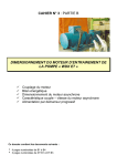
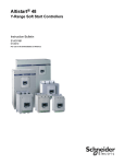
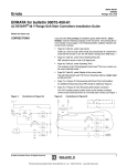
Solutions for your DC drives Maximum performance at an optimised cost Features of the product offer: > General description ......................................... 5 > Technical characteristics ................................. 6-7 > Power connection diagrams .......................... 8-9 > Control connection diagrams ......................... 10-11 > Selection guide ............................................... 12-13 > Dimensions and weights ................................. 14 > Options ............................................................. 15 Services: > Assistance with maintenance and management of your installed base ......................................... 16-17 > Our services teams can guide you through your modernisation projects .............................. 18 > ... and tackle issues of cost, lead times and quality ................................................ 19 > Solutions for your DC drives ........................... 20 + A lasting partnership We have been at your side for more than 30 years offering DC solutions. With all this experience, we know that for reasons of cost, performance and ease of maintenance, these solutions are still the most suitable ones for you. The new DCV offer satisfies all your requirements. It incorporates a wealth of applications and a services offer to help you with the maintenance and modernisation of your existing installations General description Presentation @ Variable speed drives in the DCV•4•••• range @ These drives, available in a compact are designed to control the speed or torque of compensated DC motors with separate excitation, and a rated armature current of 40 to 3000 A. They are all equipped with an excitation current regulator. @ The range consists of drives in 2 quadrants (DCV94••••) and 4 quadrants (DCV104••••) of the torque-speed plane which can be supplied by a 3-phase 230 V or 500 V mains supply (class S), or from a 690 V supply (class Y). @ The drives come with a CD-ROM containing multilingual setup documentation and any options (the printed version of the user manual is available as an option). version up to 1050 A and as a separate bridge thereafter, satisfy the most demanding applications thanks to their robust construction, the outstanding numerical control performance, not to mention numerous integrated functions. @ Variable speed drives in the DCV•4 range are particularly suitable for hoisting and material handling applications, winders/unwinders, extruders, test benches, special machines, etc… Functions The DCV•4 range incorporates, without the addition of options, a lot of application functions rationalizing the automation. By way of example, here is a list of the main functions integrated in the DCV•4•••• @ Torque servo control function @ Comparator block @ Auto-calibration of the speed and current loop @ Variable gains @ Modbus RTU, JBUS communication port Basic functions: @ +/- speed @ Inching @ 7 preset speeds @ 5 configurable linear and S ramps @ Motor thermal protection @ Programmable overload monitoring @ Current limiting according to the speed @ Automatic toggle in U feedback on loss of speed feedback @ Configurable torque control at zero speed Advanced functions: @ Brake release sequence for hoisting movements @ Dual configuration (2 motors) @ Winder/unwinder function @ PID regulato Programming terminal DCV•4•••• drives are supplied with an alphanumeric programming terminal used for: @ Controlling the drive in local mode @ Configuring the various parameters @ Programming functions @ Displaying the drive status and current values Programming and parameter-setting can also be performed: @ Via serial link @ Using the DCVCNF100 setup software Options The options offered in the DCV•4 range can be used to enhance the application functions, and to extend the drive communication capability on Schneider Electric architectures. @ Additional I/O card (1) @ CANopen communication card (1) @ Profibus communication card (1) @ Setup software and drive connection kit @ RS232/RS485 adapter for connection to a PC @ External power supply for RS485 bus @ Printed versions of multilingual user manuals @ A tropicalised version DCV•••V (1) Two different Communication I/O cards can be installed simultaneously on the same drive. 5 Technical characteristics Environmental characteristics Conforming to standards Electrical control characteristics General standards EMC immunity Clearances Safety Climate resistance Vibrations Degrees of protection CE marking UL certification Degree of protection Relative humidity Ambient air temperature DCV•D40S to M11S DCV•M14Y to M30• Operation °C Storage °C m Maximum operating altitude Operating position EN61800-1, EN50178 EN61000-4-2 immunity to interference level 6KV CD/8KV AD EN61000-4-4 level 4 According to IEC 664, IEC 664 A, degree 2 air pollution EN50178 According to EN60068-2-2, Bd test EN60068-2-6, Fc test According to EN60529 Conforming to EEC low voltage directives On request, please consult your Regional Sales Office IP20 IP00 for the separate power bridge, IP20 for the separate control module 5% to 85% during operation 0 to +40 without derating +40 to +55 with current derating of 1.25% per degree above 40°C -25 ….+ 55 1000 Current derating of 1.2% per additional 100 m of altitude Maximum angle 30° in relation to normal vertical mounting Control circuit Available internal supplies Analog inputs Analog outputs Logic inputs Temperature probe input Logic outputs Relay output Acceleration and deceleration ramp Number Main protection and safety features Drive characteristics Speed feedback Speed control Torque control Maximum speed Speed range/ (accuracy) Armature Tacho Incremental encoder Sinewave encoder Tacho Incremental encoder Sinewave encoder Depending on the output voltage V 302,9 max. KHz 150 3 2 8 1 4 2 1x115V ± 15% - 1.2A ou 1x230V ± 15% - 0.7A 50/60 ± 5Hz @ 10 V supply for reference potentiometer, max. current 10 mA @ 5 V supply for resolver, max. current 160 mA @ 5 V/15...30 V supply for encoder and digital inputs, max. current 200 mA differential programmable, 12 bits, ± 10 V, 0-10 V, 0-20 mA, 4-20 mA ± 10 V, 12 bits, 5 mA max. per output 4 fixed, 4 programmable, common charact.: 15....24 V – 5 mA per input PTC probe in accordance with DIN44081 – DIN44082 Programmable, 24 V, 20 mA max. per output 1 fixed, 1 programmable, switching capacity 1 A, AC11 at 250V @ 5 programmable linear or S ramps @ 0….65535 secondes @ Ramp for fast stop @ Internal supply fault @ Line supply undervoltage @ Armature overvoltage @ Short-circuit/earth fault @ I2t thermal protection of motor with forced ventilation, PTC prot., drive overheating prot.r @ Under-excitation of the motor @ Loss of tacho feedback, automatic toggle in U feedback @ Disconnection from the fieldbus Communication port characteristics Structure KHz 150 tr/mn 8000 1 : 1000 / (0.1%) 1 : 1000 / (0.02%) Physical interface Protocols Transmission speed Line termination impedances Electrical isolation Bus addresses 2-wire RS485/9-pin SUB-D connector Modbus RTU, JBUS bps 1200….19200 Selectable using jumpers No (yes with option) 0 to 127 1 : 10000 / (0.01%) 1 : 500 / (0.2%) Range/(accuracy Electrical power characteristics Armature circuit Supply voltage Frequency Armature output voltage DCV••••S DCV•M••Y DCV104•••S DCV94•••S DCV104M••Y DCV94M••Y V Hz V 3x230V - 3x400V - 3x440V - 3x460V - 3x480V - 3x500V 3x690V± 10% 50/60 ± 5Hz 240V – 420V – 460V – 480V - 500V – 520V 260V – 470V – 530V – 560V – 580V – 600V 720V 810V ± 10% Field coil circuit All drives V Supply voltage Hz Frequency All drives V Field coil output voltage DCV•D••S A Max. field coil current DCV•C1•S DCV•C28S to C65S DCV•4C77S to M11S DCV•4M14Y to M30• 6 1x230V - 1x400V - 1X460V ± 10% 50/60 ± 5Hz 200V - 310V - 360V (Uexc = 0.85 x U alimentation) 10 14 20 25 70 7 Power connection diagrams FAN + CONTROL - Determining the power equipment Q4 Drives: Merlin Gerin circuit-breaker Type for 115V power supply Type for 230V power supply D40S to C18S C60N bi 1A curve D C60N bi 0,5A curve D C60N bi 2A curve C C60N bi 1A curve D M14Y to M30• C28S to M11S Q6 Variateurs : (1) DCV104/94 up to C65S. (2) DCV104 up to C65S. (3) DCV104/94C77S to M30. (4) DCV104/94M14Y to M30. (5) If there is no PTC probe monitoring, wire up a 1 Kohm resistor mounted as standard. (6) Choice of control voltage DCV104/94C28S to M11S. 8 b Power terminals. @ Control card terminals. @ Power interface card terminals. Q20 Merlin Gerin circuit-breaker Type for 400V power supply D40S to D70S C60N bi 10A curve C C11S to C18S C60N bi 16A curve C C28S to C65S C60N bi 20A curve C C77S to M11S C60N bi 25A curve C M14Y to M30• C60N bi 63A curve C Type for determining equipment: Telemecanique circuit-breaker Type F1, F2, F6 D77S to M11S GV2ME05 L1 M20Y GV2ME05 Q1 M14Y to M20S GV2ME04 KM1 M27•M30 GV2ME06 See pages 10/11. 9 Control connection diagrams Logic inputs Control inputs I/O parameter factory settings Logic inputs Terminal no. 12 13 14 15 31 32 33 34 Assignment Run Operation Fast stop External fault Not assigned Not assigned Not assigned Not assigned CONTROL EXTERNAL FAULT FAST STOP START RUN VARIATOR Logic outputs Terminal no. 26 27 28 29 Assignment Acceleration Deceleration Speed threshold attained Overload available Relays Terminal no. 35-36 75-76 Assignment Drive OK Not assigned Analog inputs or or - - Sinusoidal converter 3-4 5-6 +/- 10V +/- 10V Assignment Speed reference before ramp Not assigned Not assigned Format +/- 10V +/- 10V Assignment Motor speed Motor current Analog outputs Analog outputs TOR outputs (*): 2-pole format for DCV104 only. Incremental converter (1) Input for fast stop (0 = fast stop). (2) Input for external fault (0 = external fault). (3) DCV104 only. 10 Format (*) +/- 10V Terminal no. 21-22 23-24 Analog inputs Standard Potentiometer 1k min between 0V and + 10V or -10V Terminal no. 1-2 b Power terminals. @ Control card terminals. @ Power interface card terminals. 11 Selection guide 4-quadrant range S class: Input voltage up to 3 x 500 V ± 10%/Output voltage up to 520 V Y class: Input voltage 3 x 690 V ± 10%/Output voltage 720 DCV104•••• (3) DCV104D40S (9) DCV104D70S DCV104C11S DCV104C18S DCV104C28S DCV104C42S DCV104C65S DCV104C77S DCV104M11S DCV104M15S DCV104M14Y DCV104M20S DCV104M20Y DCV104M27S DCV104M27Y DCV104M30S DCV104M30Y size 1 2 3 4 Continous armature current 40A 70A 110A 185A 280A 420A 650A 770A 1050A 1500A 1400A 2000A 2000A 2700A 2700A 3000A 3000A Continous line current Max.excit I Line choke (3) Line circuit-breaker Merlin Gerin (3) (4) Icu (kA) Telemecanique input cont.(3) Line fuses (3) (5) Fuse carrier (3) (5) Armature fuse (3) (5) Fuse carrier (3) (5) Exciter fuse (1) (5) Fuse carrier (5) Total dissipation 34A 60A 95A 160A 241A 361A 559A 662A 903A 1290A 1205A 1720A 1720A 2313A 2313A 2580A 2580A 10A 10A 14A 14A 20A 20A 20A 25A 25A 70A 70A 70A 70A 70A 70A 70A 70A LDCVD70 LDCVD70 LDCVC15 LDCVC25 LDCVC25 LDCVC53 LDCVC65 LDCVM10 LDCVM10 LDCVM14 LDCVM14 LDCVM24 LDCVM24 LDCVM24 LDCVM24 (8) (8) NS100N-TM40D NS100N-TM80D NS160N-TM125D NS250N-TM200D NS250N-TM250D NS400N-STR23SE NS630N-STR23SE NS800N-µLOGIC2.0 NS1000N-µLOGIC2.0 NS1600N-µLOGIC2.0 NS1250H-µLOGIC2.0 NS2000N-µLOGIC2.0 NS2000N-µLOGIC2.0 NS2500N-µLOGIC2.0 NS2500N-µLOGIC2.0 (8) (8) 25 25 30 30 30 30 30 40 40 40 42 65 65 65 65 LC1D32•• LC1D50•• LC1D80•• LC1D115•• LC1F185•• LC1F400•• LC1F500•• LC1F500•• LC1F630•• LC1F780•• LC1F780•• LC1BP33•31 LC1BP33•31 LC1BR33•31 LC1BR33•31 (8) (8) DCVF4M15 (1) DCVF4M19 (1) DCVF4M21 (1) DCVF4G23 (2) DCVF4G30 DCVF4E30 DCVF4G85 Built-in Built-in Built-in Built-in Built-in Built-in Built-in Built-in Built-in Built-in DF5FA61 DF5FA61 DF5FA61 DCVS7B77 DCVS7B78 DCVS7B78 DCVS7B78 Built-in Built-in Built-in Built-in Built-in Built-in Built-in Built-in Built-in Built-in DCVF4M17 (1) DCVF4M21 (1) DCVF4EAJ (2) DCVF4G23 (2) DCVF4G34 DCVF4E31 DCVF4G85 Built-in Built-in Built-in Built-in Built-in Built-in Built-in Built-in Built-in Built-in DF5FA61 DF5FA61 DCVS7B77 DCVS7B77 DCVS7B78 DCVS7B78 DCVS7B78 Built-in Built-in Built-in Built-in Built-in Built-in Built-in Built-in Built-in Built-in Built-in Built-in Built-in Built-in Built-in Built-in Built-in Built-in Built-in DCVF4M19 DCVF4M19 DCVF4M19 DCVF4M19 DCVF4M19 DCVF4M19 DCVF4M19 DCVF4M19 Built-in Built-in Built-in Built-in Built-in Built-in Built-in Built-in Built-in DF5FA61 DF5FA61 DF5FA61 DF5FA61 DF5FA61 DF5FA61 DF5FA61 DF5FA61 186W 254W 408W 553W 781W 1038W 1693W 2143W 2590W 4900W 4900W 5400W 6800W 8700W 8700W 9000W 9000W 2-quadrant range S class: Input voltage up to 3 x 500 V ± 10%/Output voltage up to 600 V – Y class: Input voltage 3 x 690 V ± 10%/Output voltage 810 DCV94•••• (3) DCV94D70S DCV94C11S DCV94C18S DCV94C28S DCV94C42S DCV94C65S DCV94C77S DCV94M10S DCV94M15S DCV94M14Y DCV94M20S DCV94M20Y DCV94M27S DCV94M27Y DCV94M30S DCV94M30Y size 1 2 3 4 Continous armature current 70A 110A 185A 280A 420A 650A 770A 1000A 1500A 1400A 2000A 2000A 2700A 2700A 3000A 3000A Continous line current Max.excit I Line choke (3) Line circuit-breake Merlin Gerin (3) (4) Icu (kA) Telemecanique input cont.(3) Line fuses (3) (5) Armature fuse (3) (5) Exciter fuse (1) (5) Fuse carrier (5) Total dissipation 60A 95A 160A 241A 361A 559A 662A 860A 1290A 1205A 1720A 1720A 2313A 2313A 2580A 2580A 10A 14A 14A 20A 20A 20A 25A 25A 70A 70A 70A 70A 70A 70A 70A 70A LDCVD70 LDCVC15 LDCVC25 LDCVC25 LDCVC53 LDCVC65 LDCVM10 LDCVM10 LDCVM14 LDCVM14 LDCVM24 LDCVM24 LDCVM24 LDCVM24 (8) (8) NS100N-TM80D NS160-TM125D NS250-TM200D NS250N-TM250D NS400N-STR23SE NS630N-STR23SE NS800N-µLOGIC2.0 NS1000N-µLOGIC2.0 NS1600N-µLOGIC2.0 NS1250H-µLOGIC2.0 NS2000N-µLOGIC2.0 NS2000N-µLOGIC2.0 NS2500N-µLOGIC2.0 NS2500N-µLOGIC2.0 (8) (8) 25 25 30 30 30 30 40 40 40 42 65 65 65 65 LC1D50•• LC1D80•• LC1D115•• LC1F185•• LC1F400•• LC1F500•• LC1F500•• LC1F630•• LC1F780•• LC1F780•• LC1BP33•31 LC1BP33•31 LC1BR33•31 LC1BR33•31 (8) (8) DCVF4M19 (1) DCVF4M21 (1) DCVF4G23 (2) DCVF4G30 DCVF4E30 DCVF4G85 Built-in Built-in Built-in Built-in Built-in Built-in Built-in Built-in Built-in Built-in DF5FA61 DF5FA61 DCVS7B77 DCVS7B78 DCVS7B78 DCVS7B78 Built-in Built-in Built-in Built-in Built-in Built-in Built-in Built-in Built-in Built-in Built-in Built-in Built-in Built-in Built-in Built-in Built-in Built-in DCVF4M19 DCVF4M19 DCVF4M19 DCVF4M19 DCVF4M19 DCVF4M19 DCVF4M19 DCVF4M19 Built-in Built-in Built-in Built-in Built-in Built-in Built-in Built-in DF5FA61 DF5FA61 DF5FA61 DF5FA61 DF5FA61 DF5FA61 DF5FA61 DF5FA61 254W 408W 553W 781W 1038W 1693W 2143W 2590W 4900W 4900W 5400W 6800W 8700W 8700W 9000W 9000W Transient characteristics of drives in the DCV range (1) Multiples of 10. (2) Multiples of 3. (3) Protection of live parts against direct contact is mandatory for voltages < 500 V, accessories not supplied. (4) Circuit-breaker thermal release to be set by the customer: motor In x 0.82 x 1.05. (5) For the quantities required, see diagrams on pages 6-7. (6) DCV104/94M2•Y drives. (7) DCV104/94M2•S drives. (8) Consult Schneider Electric. (9) Addition of suffix V for varnished version. Example: DCV104D405V. IContinuous armature (A) Io (A) Ip (A) 40 22 54 70 34 96 110 50 154 185 125 231 280 175 350 420 260 525 650 425 780 770 520 900 1000 520 1400 1050 520 1485 1400 750 2170 1500 750 2325 2000 2700 1050 1620 3000 (7) 3500 (7) 2740 (6) 3600 (6) 3000 1700 3900 The values indicated in the table above must observe the following time limits: t2 7 t1 t1 15s for ratings D40.. to C65.. t1 10s for ratings C77.. to M27.. For particular types of cyclical operation or for higher peak currents: please consult your Regional Sales Office I Simple cyclical operation. Operation can be defined by two currents: Io and Ip. Ip = peak current Io = current in steady state Ip Io t 0 12 t1 t2 T 13 Options Dimensions and weights Compact drives I/O extension cards DCV a (mm) b (mm) c (mm) Weight (Kg) DCV104D40S DCV•D70S DCV•C11S DCV•C18S DCV•C28S DCV•C42S DCV•C65S DCV•C77S DCV104M11S DCV94M10S 263 263 263 263 311 311 311 521 521 521 360 360 360 360 388 388 388 510 510 510 274 274 274 274 338 338 368 402 402 402 8.4 8.8 10.8 10.8 24.5 29.5 32 61 65 65 DCVS5V62 4 discrete inputs (+15...+30V; 3.2...6.4 mA) 4 discrete transistor outputs (+15...+30V; 20 mA Max) 2 ANA outputs (± 10 V – 5 mA) b CANopen communication card DCVS5Z27 CAN 2.0 protocol (11-bit identifier) Transmission speed: up to 1 Mbps Addresses: 1...128 1 SDO for access to all drive parameters c 1 PDO of 4 input/output words a Profibus communication card DCVS5E25 Profibus protocol Transmission speed: Up to 12 Mbauds Drives with separate bridge Slaves: 125 Max. DCV a (mm) b (mm) c (mm) Weight (Kg) DCV104M15S DCV104M14Y DCV104M20S DCV104M20Y DCV104M27S DCV104M27Y DCV104M30S DCV104M30Y DCV94M15S DCV94M14Y DCV94M20S DCV94M20Y DCV94M27S DCV94M27Y DCV94M30S DCV94M30Y 500 500 500 620 712 712 784 784 500 500 500 620 712 712 784 784 1310 1310 1310 1314 1535 1335 1640 1640 760 760 760 764 785 775 960 960 375 375 375 475 490 475 460 460 275 275 275 360 395 395 415 415 130 130 130 170 240 240 330 330 70 70 70 100 140 140 215 215 Control module 360 263 274 8.4 Exchange mode: 4 PDC IN + 4 PDC OUT 4 input PKW words + 4 output PKW words b Setup software and connection kit DCVCNF100 Configuration, use, diagnostics, display of drive parameters on PC Windows 95 environment® or later Including RS232/USB connection kit 5 User files c a Read/write all the parameters Help with programming on startup Oscilloscope function Up to 32 networked drives can be managed RS232/RS485 adaptator DCVS546Z Drive connected to a PC RS232 port RS485 interface in multidrop configuration Allows up to 32 RS485 connection points b 5 External power supply for bus RS485DCVS5Z40 External power supply for RS485 bus in multidrop configuration The network and motor armature connections are made via busbars located at the bottom of the separate power bridge. Up to 32 RS485 connection points +15...+30 V power supply, +5 V – 1 A output c a Printed User’s Manual DCVDOC100•• User’s Manual in French DCVDOC100FR User’s Manual in English DCVDOC100EN Setup, parameter-setting and maintenance document. (User’s Manual on CD supplied with the drive). Line chokes Ref. LDCVD70 LDCVC15 LDCVC25 LDCVC53 LDCVC65 LDCVM10 LDCVM14 LDCVM24 a (mm) b (mm) c (mm) Dissipation Weight (Kg) 110W 215 150 180 9 280W 240 170 270 20 350W 240 220 270 26 670W 465 225 380 50 730W 465 275 390 60 1300W 420 310 435 65 1450W 550 340 420 90 1860W 590 385 420 140 b a c a c Connections via 6 busbars except for LDCVD70 (connection via terminal blocks). Lifting rings on chokes >= LDCVC53. b 14 15 Assistance with maintenance and management of your installed base Technical support, repair and exchange Should you experience faults or malfunctions on our variable speed drives, Schneider Electric is well aware of the strategic importance of driven machines and can respond very promptly 24 hours a day - 7 days a week Maintenance contract You are keen to ensure the longevity of your equipment, optimise your stocks of replacement parts, rationalise your installed base, and increase your ratio of services to production. Our maintenance offer contract is based on 3 predefined contract types: Bronze, Silver and Gold, or can be tailored to meet your exact requirements with an “A la carte” contract. + Our service teams can offer you the solution best suited to your situation: @ An online technical analysis to find the optimum solution @ Express repair of defective equipment, excluding weekends and public holidays, for drives < 1000 A @ 24/7 service response from a technician with a predefined replacement parts kit for each drive type @ 24/7 replacement of the faulty drive with a new equivalent. This system also applies to the old type VL1/RTV54-64/541641/74-84 ranges (for third-party equipment, please consult your Regional Sales Office) Wearing parts and replacement subassembly Power fuses (for drives with built-in fuses) Exciter fuses (for drives with built-in fuses) 2-thyristor subassemblies Preassembled with heatsink For DCV104• four-quadrant drives, a plug-in base consists of two thyristors head-to-tail. For DCV94• two-quadrant drives, a plug-in base consists of two thyristors in serie Power section fans Control module for drives with separate power bridges Control card Parameter-setting terminal 16 For DCV - A drive 104C77S (6) 104M11S (6) – 94C77S (3) 94M10S (3) 104M15S (6) 104M14Y (6) 94M15S (6) - 104M30S (12) - 94M30S (12) - 94M30Y (12) 94M14Y (6) 104M20S (6) – 94M20S (6) - 94M20Y (6) 104M20Y(12) 94M27Y (12) - 94M275 (12) - 104M27(12) 104M27Y (12) 104M30S(12) - 94M30S(12) - 94M30Y(12) 104M30Y(12) D40S to C18S (2) •C28S to 94MI0S ou 104M11S (2) 104M15S – Top plug-in base (3) 104M15S – Bottom plug-in base (3) 104M14Y – Top plug-in base (3) 104M14Y – Bottom plug-in base (3) 104M20S – Top plug-in base (3) 104M20S – Bottom plug-in base (3) 104M20Y – Top plug-in base (3) 104M20Y – Bottom plug-in base (3) 104M27S – Top plug-in base (3) 104M27S – Bottom plug-in base (3) 104M27Y – Top plug-in base (3) 104M27Y – Bottom plug-in base (3) 94M15S – Single-phase plug-in base (3) 94M14Y – Single-phase plug-in base (3) 94M20S – Single-phase plug-in base (3) 94M20Y – Single-phase plug-in base (3) 94M27S – Single-phase plug-in base (3) 94M27Y – Single-phase plug-in base (3) 104M30S – Top plug-in base (3) 104M30S – Bottom plug-in base (3) 104M30Y – Top plug-in base (3) 104M30Y – Bottom plug-in base (3) 94M30S – Single-phase plug-in base (3) 94M30Y – Single-phase plug-in base (3) For separate control units DCVS4B21(1) and DCVS4B22 (1) and drives •D70S (1) •C11S (1) •C18S (1) •C28S (2) •C42S (2) •C65S (2) •C77S (3) to •M11S (3) Power bridges •M14Y- (2) •M15S (2) •M20S (2) Power bridges •M20Y (2) Power bridges •M27• (2) •M30• (2) 104M••S (1) – 94M••S (1) 104M••Y (1) – 94M••Y (1) All drives (1) All drives(1) Référence - B DCVF4G59 (1) DCVF4G60 (2) DCVF4G61 (2) DCVS7793 (3) DCVS7804 (1) DCVS7799 (3) DCVS7798 (3) DCVS7802 (3) DCVS7794 (2) DCVS7797 (3) DCVS7805 (1) DCVS7799 DCVS7193 DCV824B DCV823B DCVS7B20 (1) DCVS7B26 (1) DCVS7B23 (1) DCVS7B29 (1) DCVS7B21 (1) DCVS7B27 (1) DCVS7B24 (1) DCVS7B30 (1) DCVS7B22 (1) DCVS7B28 (1) DCVS7B25 (1) DCVS7B31 (1) DCVS7B01 (1) DCVS7B04 (1) DCVS7B02 (1) DCVS7B05 (1) DCVS7B03 (1) DCVS7B06 (1) DCVS7B34 (1) DCVS7B36 (1) DCVS7B35 (1) DCVS7B37 (1) DCVS7B32 (1) DCVS7B33 (1) DCVS7G76 (1) A The values in brackets indicate the quantities fitted on each drive B The values in brackets indicate the product packaging DCVS7G71 DCVS7G78 DCVS7G17 DCVS7R24 DCVS7R25 DCVS7R26 DCVS4B21 DCVS4B22 DCVS5N45 DCVS5P0S (1) (1) (1) (1) (1) (1) (1) (1) (1) (1) 17 Our services teams can guide you through your modernisation projects... ...and tackle issues of cost, lead times and quality You need to replace an existing variable speed drive Mining industry: modernising within a guaranteed timescale You want to replace a Rectivar drive quickly and safely, with a device from the new range. The table below lists the possible options depending on your budget. For a more in-depth study, our service experts can guide you and suggest detailed costings (for third-party products and VD1/RTV44/RTV04 single-phase drives, please consult your Regional Sales Office). Customer situation Replacing a TSX7 + Rectivar architecture on a 90 T overhead crane. The work needs to be performed during production downtime. In the event of a problem, it must be possible to return to the original architecture and restart. Project management Tools, methods and experienced project leaders, when you are looking for a strong commitment from us to your modernisation projects. Main steps in the project Table of correspondence with the old ranges RTV84••/RTV74•• and RTV64••/RTV54•• @ Detailed analysis of the existing system: communication, PLC programs, RTV641D16Q RTV641D32Q/S RTV641D48Q/S RTV641D72Q/S RTV641C18Q/S RTV641C27Q/S RTV641C40Q/S RTV641C65Q/S RTV641C80Q/S RTV641M12Q/S RTV641M12Y RTV641M17Q/S RTV641M17Y RTV641M30Q/S/Y RTV541D32Q/S RTV541D48Q/S RTV541D72Q/S RTV541C18Q/S RTV541C27Q/S RTV541C40Q/S RTV541C65Q/S RTV541C80Q/S RTV541M12Q/S RTV541M12Y RTV541M17Q/S RTV541M17Y RTV541M30Q/S/Y RTV84D16Q RTV84D32Q/S RTV84D48Q/S RTV84D72Q/S RTV84C18Q/S RTV84C27Q/S RTV84C40Q/S RTV84C65Q/S RTV84C80Q/S RTV84M12Q/S RTV84M12Y RTV84M17Q/S RTV84M17Y RTV84M30Q/S/Y RTV74D32Q/S RTV74D48Q/S RTV74D72Q/S RTV74C18Q/S RTV74C27Q/S RTV74C40Q/S RTV74C65Q/S RTV74C80Q/S RTV74M12Q/S RTV74M12Y RTV74M17Q/S RTV74M17Y RTV74M30Q/S/Y DCV104D40S DCV104D40S DCV104D70S DCV104C11S DCV104C28S DCV104C28S DCV104C42S DCV104C77S DCV104M11S DCV104M15S DCV104M14Y DCV104M20S DCV104M20Y DCV104M30S/Y DCV94D70S DCV94D70S DCV94C11S DCV94C28S DCV94C28S DCV94C42S DCV94C77S DCV94M10S DCV94M15S DCV94M14Y DCV94M20S DCV94M20Y DCV94M30S/Y You are in charge of a modernisation project To satisfy your requirements, we can offer you two complementary approaches: Project management and Consultancy & expertise. Project management drive control and conditions of use @ Replacement of all the variable speed drives @ Migration software, creation of system restore kits, installation of Unity CPUs and maintenance of the TSX 7 I/O @ Training the maintenance team and drawing up the technical support contract @ Complete migration of the wiring Customer benefits @ Reduction of risks due to the technical solution and the project management method @ Commitment to 24/7 support on a tried-and-tested system with which we are completely familiar Metallurgy industry: ensuring the best architecture Consultancy and expertise Customer situation Additional skills and methodology to identify opportunities, nail down key points and simplify your project management. Definition of the best drive architecture for modernisation of an annealing line with the speed increased by 15%. The future architecture will be designed with AC or DC motors. You are looking for a strong commitment from us to your modernisation project. You are counting on the experience of our project managers and the support of our tools and methods. Main steps in the project: Consultancy and expertise in static and dynamic mode, communication modes used to manage references and operating modes @ Feasibility study of AC solution, motor sizing and definition of control diagrams @ Presentation of possible solutions, associated budgets and project implementation methods You are looking for additional skills and methodology. Our experts and consultants can help you to analyse your existing base, and then define and implement the solution. @ Detailed diagnostics of the existing base: Measurement of motor loads Customer benefits @ Schneider’s commitment to the system’s overall performance @ Total autonomy in implementation of the recommended solutions 18 19 Solutions for your DC drives A high-performance offer... @ Easy replacement of the old Rectivar ranges @ Optimised developments by the provision of numerous built-in application functions. @ Simplified integration in Schneider Electric architectures. ... and services for your strategic machines @ At your side 24 hours a day - 7 days a week. @ A customized approach for transition of the Rectivar ranges to the new offer. @ The garantee to reduce the risks and costs of your modernisation projects. This offer is included in our full range of services for your installed base. Contact us for further information. Schneider Electric Industries SAS Head Office 35 rue Joseph Monier CS 30323 92506 Rueil-Malmaison www.schneider-electric.com SERED107028EN As standards, specifications and designs change from time to time, please ask for confirmation of the information given in this publication. Printed on recycled paper. Publication: Schneider Electric Industries SAS - All rights reserved Design: Schneider Electric Industries SAS Print: 11/2008