1
Projector Toolset
Reference manual
R5976924/05
16/04/2009
Barco nv Events
Noordlaan 5, B-8520 Kuurne
Phone: +32 56.36.89.70
Fax: +32 56.36.88.24
E-mail: [email protected]
Visit us at the web: www.barco.com
Printed in Belgium
Changes
Barco provides this manual ’as is’ without warranty of any kind, either expressed or implied, including but not
limited to the implied warranties or merchantability and fitness for a particular purpose. Barco may make improvements and/or changes to the product(s) and/or the program(s) described in this publication at any time
without notice.
This publication could contain technical inaccuracies or typographical errors. Changes are periodically made
to the information in this publication; these changes are incorporated in new editions of this publication.
Copyright ©
All rights reserved. No part of this document may be copied, reproduced or translated. It shall not otherwise
be recorded, transmitted or stored in a retrieval system without the prior written consent of Barco.
Trademarks
Brand and product names mentioned in this manual may be trademarks, registered trademarks or copyrights
of their respective holders. All brand and product names mentioned in this manual serve as comments or
examples and are not to be understood as advertising for the products or their manufacturers.
Table of contents
TABLE OF CONTENTS
1. Basic concepts .....................................................................................7
1.1
1.2
1.3
1.4
Introduction . .. .. .. .. .. .. .. .. .. .. .. .. .. .. .. .. .. .. .. .. .. .. .. .. .. .. .. .. .. .. .. .. .. .. .. .. .. .. .. .. .. .. .. .. .. .. .. .. .. .. 7
About a Configuration . .. .. .. .. .. .. .. .. .. .. .. .. .. .. .. .. .. .. .. .. .. .. .. .. .. .. .. .. .. .. .. .. .. .. .. .. .. .. .. .. .. .. .. .. 7
About a Snapshot .. .. .. .. .. .. .. .. .. .. .. .. .. .. .. .. .. .. .. .. .. .. .. .. .. .. .. .. .. .. .. .. .. .. .. .. .. .. .. .. .. .. .. .. .. .. .. 7
About storing Configurations and Snapshots . .. .. .. .. .. .. .. .. .. .. .. .. .. .. .. .. .. .. .. .. .. .. .. .. .. .. .. .. .. .. .. 7
2. Installation ...........................................................................................9
2.1
2.2
2.3
2.4
2.5
2.6
2.7
General requirements . .. .. .. .. .. .. .. .. .. .. .. .. .. .. .. .. .. .. .. .. .. .. .. .. .. .. .. .. .. .. .. .. .. .. .. .. .. .. .. .. .. .. .. .. 9
Free download of Projector Toolset .. .. .. .. .. .. .. .. .. .. .. .. .. .. .. .. .. .. .. .. .. .. .. .. .. .. .. .. .. .. .. .. .. .. .. .. . 10
Projector Toolset installation .. .. .. .. .. .. .. .. .. .. .. .. .. .. .. .. .. .. .. .. .. .. .. .. .. .. .. .. .. .. .. .. .. .. .. .. .. .. .. .. . 10
Starting up .. .. .. .. .. .. .. .. .. .. .. .. .. .. .. .. .. .. .. .. .. .. .. .. .. .. .. .. .. .. .. .. .. .. .. .. .. .. .. .. .. .. .. .. .. .. .. .. .. .. . 12
Manual installation of a device plug-in . .. .. .. .. .. .. .. .. .. .. .. .. .. .. .. .. .. .. .. .. .. .. .. .. .. .. .. .. .. .. .. .. .. .. . 15
Uninstall Projector Toolset .. .. .. .. .. .. .. .. .. .. .. .. .. .. .. .. .. .. .. .. .. .. .. .. .. .. .. .. .. .. .. .. .. .. .. .. .. .. .. .. .. . 17
About this manual .. .. .. .. .. .. .. .. .. .. .. .. .. .. .. .. .. .. .. .. .. .. .. .. .. .. .. .. .. .. .. .. .. .. .. .. .. .. .. .. .. .. .. .. .. .. . 17
3. Menus ............................................................................................... 19
3.1
3.2
3.3
3.4
3.5
3.6
3.7
3.8
General.. .. .. .. .. .. .. .. .. .. .. .. .. .. .. .. .. .. .. .. .. .. .. .. .. .. .. .. .. .. .. .. .. .. .. .. .. .. .. .. .. .. .. .. .. .. .. .. .. .. .. .. . 19
Menu and button bar. .. .. .. .. .. .. .. .. .. .. .. .. .. .. .. .. .. .. .. .. .. .. .. .. .. .. .. .. .. .. .. .. .. .. .. .. .. .. .. .. .. .. .. .. . 19
Main window.. .. .. .. .. .. .. .. .. .. .. .. .. .. .. .. .. .. .. .. .. .. .. .. .. .. .. .. .. .. .. .. .. .. .. .. .. .. .. .. .. .. .. .. .. .. .. .. .. . 20
Short cut keys .. .. .. .. .. .. .. .. .. .. .. .. .. .. .. .. .. .. .. .. .. .. .. .. .. .. .. .. .. .. .. .. .. .. .. .. .. .. .. .. .. .. .. .. .. .. .. .. . 21
Workspace Explorer . .. .. .. .. .. .. .. .. .. .. .. .. .. .. .. .. .. .. .. .. .. .. .. .. .. .. .. .. .. .. .. .. .. .. .. .. .. .. .. .. .. .. .. .. . 21
How to adjust a setting .. .. .. .. .. .. .. .. .. .. .. .. .. .. .. .. .. .. .. .. .. .. .. .. .. .. .. .. .. .. .. .. .. .. .. .. .. .. .. .. .. .. .. . 22
About Projector Toolset.. .. .. .. .. .. .. .. .. .. .. .. .. .. .. .. .. .. .. .. .. .. .. .. .. .. .. .. .. .. .. .. .. .. .. .. .. .. .. .. .. .. .. . 22
Snapshot management.. .. .. .. .. .. .. .. .. .. .. .. .. .. .. .. .. .. .. .. .. .. .. .. .. .. .. .. .. .. .. .. .. .. .. .. .. .. .. .. .. .. .. . 26
3.8.1 About snapshots.. .. .. .. .. .. .. .. .. .. .. .. .. .. .. .. .. .. .. .. .. .. .. .. .. .. .. .. .. .. .. .. .. .. .. .. .. .. .. .. .. .. .. .. . 27
3.8.2 Managing snapshots . .. .. .. .. .. .. .. .. .. .. .. .. .. .. .. .. .. .. .. .. .. .. .. .. .. .. .. .. .. .. .. .. .. .. .. .. .. .. .. .. .. . 27
3.8.3 Take a snapshot .. .. .. .. .. .. .. .. .. .. .. .. .. .. .. .. .. .. .. .. .. .. .. .. .. .. .. .. .. .. .. .. .. .. .. .. .. .. .. .. .. .. .. .. . 28
3.8.4 Apply a snapshot . .. .. .. .. .. .. .. .. .. .. .. .. .. .. .. .. .. .. .. .. .. .. .. .. .. .. .. .. .. .. .. .. .. .. .. .. .. .. .. .. .. .. .. . 30
3.8.5 Delete a snapshot .. .. .. .. .. .. .. .. .. .. .. .. .. .. .. .. .. .. .. .. .. .. .. .. .. .. .. .. .. .. .. .. .. .. .. .. .. .. .. .. .. .. .. . 31
3.8.6 Add shot cut key to a snapshot . .. .. .. .. .. .. .. .. .. .. .. .. .. .. .. .. .. .. .. .. .. .. .. .. .. .. .. .. .. .. .. .. .. .. .. . 32
3.8.7 Remove shot cut key association. .. .. .. .. .. .. .. .. .. .. .. .. .. .. .. .. .. .. .. .. .. .. .. .. .. .. .. .. .. .. .. .. .. .. . 33
4. Preferences ........................................................................................ 35
4.1
4.2
4.3
4.4
4.5
4.6
4.7
Introduction . .. .. .. .. .. .. .. .. .. .. .. .. .. .. .. .. .. .. .. .. .. .. .. .. .. .. .. .. .. .. .. .. .. .. .. .. .. .. .. .. .. .. .. .. .. .. .. .. .. . 35
Start up the preferences. .. .. .. .. .. .. .. .. .. .. .. .. .. .. .. .. .. .. .. .. .. .. .. .. .. .. .. .. .. .. .. .. .. .. .. .. .. .. .. .. .. .. . 35
Access level .. .. .. .. .. .. .. .. .. .. .. .. .. .. .. .. .. .. .. .. .. .. .. .. .. .. .. .. .. .. .. .. .. .. .. .. .. .. .. .. .. .. .. .. .. .. .. .. .. . 36
Software Appearance.. .. .. .. .. .. .. .. .. .. .. .. .. .. .. .. .. .. .. .. .. .. .. .. .. .. .. .. .. .. .. .. .. .. .. .. .. .. .. .. .. .. .. .. . 37
Bug report setup . .. .. .. .. .. .. .. .. .. .. .. .. .. .. .. .. .. .. .. .. .. .. .. .. .. .. .. .. .. .. .. .. .. .. .. .. .. .. .. .. .. .. .. .. .. .. . 40
Logging.. .. .. .. .. .. .. .. .. .. .. .. .. .. .. .. .. .. .. .. .. .. .. .. .. .. .. .. .. .. .. .. .. .. .. .. .. .. .. .. .. .. .. .. .. .. .. .. .. .. .. .. . 41
Workspace selection. .. .. .. .. .. .. .. .. .. .. .. .. .. .. .. .. .. .. .. .. .. .. .. .. .. .. .. .. .. .. .. .. .. .. .. .. .. .. .. .. .. .. .. .. . 42
5. Configurator ....................................................................................... 45
5.1
5.2
5.3
5.4
Introduction . .. .. .. .. .. .. .. .. .. .. .. .. .. .. .. .. .. .. .. .. .. .. .. .. .. .. .. .. .. .. .. .. .. .. .. .. .. .. .. .. .. .. .. .. .. .. .. .. .. . 45
Configurator window . .. .. .. .. .. .. .. .. .. .. .. .. .. .. .. .. .. .. .. .. .. .. .. .. .. .. .. .. .. .. .. .. .. .. .. .. .. .. .. .. .. .. .. .. . 45
Create a new configuration . .. .. .. .. .. .. .. .. .. .. .. .. .. .. .. .. .. .. .. .. .. .. .. .. .. .. .. .. .. .. .. .. .. .. .. .. .. .. .. .. . 45
Add projector to a configuration .. .. .. .. .. .. .. .. .. .. .. .. .. .. .. .. .. .. .. .. .. .. .. .. .. .. .. .. .. .. .. .. .. .. .. .. .. .. . 46
5.4.1 Add projector.. .. .. .. .. .. .. .. .. .. .. .. .. .. .. .. .. .. .. .. .. .. .. .. .. .. .. .. .. .. .. .. .. .. .. .. .. .. .. .. .. .. .. .. .. .. . 47
5.4.2 General properties . .. .. .. .. .. .. .. .. .. .. .. .. .. .. .. .. .. .. .. .. .. .. .. .. .. .. .. .. .. .. .. .. .. .. .. .. .. .. .. .. .. .. . 48
5.4.3 Connection setup. .. .. .. .. .. .. .. .. .. .. .. .. .. .. .. .. .. .. .. .. .. .. .. .. .. .. .. .. .. .. .. .. .. .. .. .. .. .. .. .. .. .. .. . 48
5.4.3.1 Set up a serial connection . .. .. .. .. .. .. .. .. .. .. .. .. .. .. .. .. .. .. .. .. .. .. .. .. .. .. .. .. .. .. .. .. .. .. .. . 49
5.4.3.2 Set up a Ethernet connection.. .. .. .. .. .. .. .. .. .. .. .. .. .. .. .. .. .. .. .. .. .. .. .. .. .. .. .. .. .. .. .. .. .. . 51
5.4.4 Decorator setup. .. .. .. .. .. .. .. .. .. .. .. .. .. .. .. .. .. .. .. .. .. .. .. .. .. .. .. .. .. .. .. .. .. .. .. .. .. .. .. .. .. .. .. .. . 55
5.5 Reconnect a projector . .. .. .. .. .. .. .. .. .. .. .. .. .. .. .. .. .. .. .. .. .. .. .. .. .. .. .. .. .. .. .. .. .. .. .. .. .. .. .. .. .. .. .. . 57
5.6 Move projector to a group . .. .. .. .. .. .. .. .. .. .. .. .. .. .. .. .. .. .. .. .. .. .. .. .. .. .. .. .. .. .. .. .. .. .. .. .. .. .. .. .. .. . 59
5.7 Edit projector properties . .. .. .. .. .. .. .. .. .. .. .. .. .. .. .. .. .. .. .. .. .. .. .. .. .. .. .. .. .. .. .. .. .. .. .. .. .. .. .. .. .. .. . 60
5.8 Configuration preview . .. .. .. .. .. .. .. .. .. .. .. .. .. .. .. .. .. .. .. .. .. .. .. .. .. .. .. .. .. .. .. .. .. .. .. .. .. .. .. .. .. .. .. . 62
5.9 Configuration properties. .. .. .. .. .. .. .. .. .. .. .. .. .. .. .. .. .. .. .. .. .. .. .. .. .. .. .. .. .. .. .. .. .. .. .. .. .. .. .. .. .. .. . 62
5.10 Preview layout properties . .. .. .. .. .. .. .. .. .. .. .. .. .. .. .. .. .. .. .. .. .. .. .. .. .. .. .. .. .. .. .. .. .. .. .. .. .. .. .. .. .. . 63
R5976924 PROJECTOR TOOLSET 16/04/2009
1
Table of contents
5.10.1 Background color. .. .. .. .. .. .. .. .. .. .. .. .. .. .. .. .. .. .. .. .. .. .. .. .. .. .. .. .. .. .. .. .. .. .. .. .. .. .. .. .. .. .. .. . 63
5.10.2 Background image . .. .. .. .. .. .. .. .. .. .. .. .. .. .. .. .. .. .. .. .. .. .. .. .. .. .. .. .. .. .. .. .. .. .. .. .. .. .. .. .. .. .. . 66
5.10.3 Rearrange pictographs in preview pane . .. .. .. .. .. .. .. .. .. .. .. .. .. .. .. .. .. .. .. .. .. .. .. .. .. .. .. .. .. .. . 67
5.11 Multiple projector selection.. .. .. .. .. .. .. .. .. .. .. .. .. .. .. .. .. .. .. .. .. .. .. .. .. .. .. .. .. .. .. .. .. .. .. .. .. .. .. .. .. . 68
6. Configurator, General projector settings ................................................... 71
6.1
6.2
6.3
6.4
6.5
6.6
6.7
6.8
Start up.. .. .. .. .. .. .. .. .. .. .. .. .. .. .. .. .. .. .. .. .. .. .. .. .. .. .. .. .. .. .. .. .. .. .. .. .. .. .. .. .. .. .. .. .. .. .. .. .. .. .. .. . 71
Control interface.. .. .. .. .. .. .. .. .. .. .. .. .. .. .. .. .. .. .. .. .. .. .. .. .. .. .. .. .. .. .. .. .. .. .. .. .. .. .. .. .. .. .. .. .. .. .. . 73
Basic controls, Lamp ON/OFF.. .. .. .. .. .. .. .. .. .. .. .. .. .. .. .. .. .. .. .. .. .. .. .. .. .. .. .. .. .. .. .. .. .. .. .. .. .. .. . 73
Basic controls, pause setting . .. .. .. .. .. .. .. .. .. .. .. .. .. .. .. .. .. .. .. .. .. .. .. .. .. .. .. .. .. .. .. .. .. .. .. .. .. .. .. . 74
Basic control, Text ON/OFF. .. .. .. .. .. .. .. .. .. .. .. .. .. .. .. .. .. .. .. .. .. .. .. .. .. .. .. .. .. .. .. .. .. .. .. .. .. .. .. .. . 75
Test pattern short cuts . .. .. .. .. .. .. .. .. .. .. .. .. .. .. .. .. .. .. .. .. .. .. .. .. .. .. .. .. .. .. .. .. .. .. .. .. .. .. .. .. .. .. .. . 75
Test patterns, others . .. .. .. .. .. .. .. .. .. .. .. .. .. .. .. .. .. .. .. .. .. .. .. .. .. .. .. .. .. .. .. .. .. .. .. .. .. .. .. .. .. .. .. .. . 76
Advanced controls . .. .. .. .. .. .. .. .. .. .. .. .. .. .. .. .. .. .. .. .. .. .. .. .. .. .. .. .. .. .. .. .. .. .. .. .. .. .. .. .. .. .. .. .. .. . 77
6.8.1 Input locking .. .. .. .. .. .. .. .. .. .. .. .. .. .. .. .. .. .. .. .. .. .. .. .. .. .. .. .. .. .. .. .. .. .. .. .. .. .. .. .. .. .. .. .. .. .. . 77
6.8.2 Source switching . .. .. .. .. .. .. .. .. .. .. .. .. .. .. .. .. .. .. .. .. .. .. .. .. .. .. .. .. .. .. .. .. .. .. .. .. .. .. .. .. .. .. .. . 80
6.8.3 No signal .. .. .. .. .. .. .. .. .. .. .. .. .. .. .. .. .. .. .. .. .. .. .. .. .. .. .. .. .. .. .. .. .. .. .. .. .. .. .. .. .. .. .. .. .. .. .. .. . 81
6.8.4 Image load mode . .. .. .. .. .. .. .. .. .. .. .. .. .. .. .. .. .. .. .. .. .. .. .. .. .. .. .. .. .. .. .. .. .. .. .. .. .. .. .. .. .. .. .. . 82
6.8.5 Minimum frame delay .. .. .. .. .. .. .. .. .. .. .. .. .. .. .. .. .. .. .. .. .. .. .. .. .. .. .. .. .. .. .. .. .. .. .. .. .. .. .. .. .. . 83
6.8.6 Contrast enhancement. .. .. .. .. .. .. .. .. .. .. .. .. .. .. .. .. .. .. .. .. .. .. .. .. .. .. .. .. .. .. .. .. .. .. .. .. .. .. .. .. . 84
6.8.7 Calibrate lens zoom and focus .. .. .. .. .. .. .. .. .. .. .. .. .. .. .. .. .. .. .. .. .. .. .. .. .. .. .. .. .. .. .. .. .. .. .. .. . 85
6.8.8 Lens settings for all layouts . .. .. .. .. .. .. .. .. .. .. .. .. .. .. .. .. .. .. .. .. .. .. .. .. .. .. .. .. .. .. .. .. .. .. .. .. .. . 86
6.8.9 Auto picture alignment . .. .. .. .. .. .. .. .. .. .. .. .. .. .. .. .. .. .. .. .. .. .. .. .. .. .. .. .. .. .. .. .. .. .. .. .. .. .. .. .. . 87
6.8.10 LCD timeout settings . .. .. .. .. .. .. .. .. .. .. .. .. .. .. .. .. .. .. .. .. .. .. .. .. .. .. .. .. .. .. .. .. .. .. .. .. .. .. .. .. .. . 88
6.9 Maintenance .. .. .. .. .. .. .. .. .. .. .. .. .. .. .. .. .. .. .. .. .. .. .. .. .. .. .. .. .. .. .. .. .. .. .. .. .. .. .. .. .. .. .. .. .. .. .. .. .. . 89
6.9.1 Reset to factory defaults . .. .. .. .. .. .. .. .. .. .. .. .. .. .. .. .. .. .. .. .. .. .. .. .. .. .. .. .. .. .. .. .. .. .. .. .. .. .. .. . 89
6.9.2 Reset electronics . .. .. .. .. .. .. .. .. .. .. .. .. .. .. .. .. .. .. .. .. .. .. .. .. .. .. .. .. .. .. .. .. .. .. .. .. .. .. .. .. .. .. .. . 90
7. Configurator, Projector alignment settings ................................................ 93
7.1
Lens control. .. .. .. .. .. .. .. .. .. .. .. .. .. .. .. .. .. .. .. .. .. .. .. .. .. .. .. .. .. .. .. .. .. .. .. .. .. .. .. .. .. .. .. .. .. .. .. .. .. . 93
7.1.1 Lens shift .. .. .. .. .. .. .. .. .. .. .. .. .. .. .. .. .. .. .. .. .. .. .. .. .. .. .. .. .. .. .. .. .. .. .. .. .. .. .. .. .. .. .. .. .. .. .. .. . 93
7.1.2 Lens mid position. .. .. .. .. .. .. .. .. .. .. .. .. .. .. .. .. .. .. .. .. .. .. .. .. .. .. .. .. .. .. .. .. .. .. .. .. .. .. .. .. .. .. .. . 94
7.1.3 Lens zoom .. .. .. .. .. .. .. .. .. .. .. .. .. .. .. .. .. .. .. .. .. .. .. .. .. .. .. .. .. .. .. .. .. .. .. .. .. .. .. .. .. .. .. .. .. .. .. . 94
7.1.4 Lens focus. .. .. .. .. .. .. .. .. .. .. .. .. .. .. .. .. .. .. .. .. .. .. .. .. .. .. .. .. .. .. .. .. .. .. .. .. .. .. .. .. .. .. .. .. .. .. .. . 94
7.2 Alignment pattern .. .. .. .. .. .. .. .. .. .. .. .. .. .. .. .. .. .. .. .. .. .. .. .. .. .. .. .. .. .. .. .. .. .. .. .. .. .. .. .. .. .. .. .. .. .. . 95
7.3 Gamma adjustment .. .. .. .. .. .. .. .. .. .. .. .. .. .. .. .. .. .. .. .. .. .. .. .. .. .. .. .. .. .. .. .. .. .. .. .. .. .. .. .. .. .. .. .. .. . 96
7.4 Individual color selection .. .. .. .. .. .. .. .. .. .. .. .. .. .. .. .. .. .. .. .. .. .. .. .. .. .. .. .. .. .. .. .. .. .. .. .. .. .. .. .. .. .. . 97
7.5 Horizontal keystone correction . .. .. .. .. .. .. .. .. .. .. .. .. .. .. .. .. .. .. .. .. .. .. .. .. .. .. .. .. .. .. .. .. .. .. .. .. .. .. . 97
7.6 Blanking adjustment . .. .. .. .. .. .. .. .. .. .. .. .. .. .. .. .. .. .. .. .. .. .. .. .. .. .. .. .. .. .. .. .. .. .. .. .. .. .. .. .. .. .. .. .. . 98
7.7 ScenergiX . .. .. .. .. .. .. .. .. .. .. .. .. .. .. .. .. .. .. .. .. .. .. .. .. .. .. .. .. .. .. .. .. .. .. .. .. .. .. .. .. .. .. .. .. .. .. .. .. .. . 100
7.7.1 Introduction.. .. .. .. .. .. .. .. .. .. .. .. .. .. .. .. .. .. .. .. .. .. .. .. .. .. .. .. .. .. .. .. .. .. .. .. .. .. .. .. .. .. .. .. .. .. . 100
7.7.2 Preparations .. .. .. .. .. .. .. .. .. .. .. .. .. .. .. .. .. .. .. .. .. .. .. .. .. .. .. .. .. .. .. .. .. .. .. .. .. .. .. .. .. .. .. .. .. . 101
7.7.3 ScenergiX activation . .. .. .. .. .. .. .. .. .. .. .. .. .. .. .. .. .. .. .. .. .. .. .. .. .. .. .. .. .. .. .. .. .. .. .. .. .. .. .. .. . 101
7.7.4 ScenergiX overlap zone (horizontal ScenergiX) .. .. .. .. .. .. .. .. .. .. .. .. .. .. .. .. .. .. .. .. .. .. .. .. .. . 102
7.7.5 ScenergiX overlap zone (vertical ScenergiX) . .. .. .. .. .. .. .. .. .. .. .. .. .. .. .. .. .. .. .. .. .. .. .. .. .. .. . 103
7.7.6 ScenergiX size adjustment (white level adjustment) . .. .. .. .. .. .. .. .. .. .. .. .. .. .. .. .. .. .. .. .. .. .. . 104
7.7.7 Adjusting the black level of the images .. .. .. .. .. .. .. .. .. .. .. .. .. .. .. .. .. .. .. .. .. .. .. .. .. .. .. .. .. .. . 106
8. Configurator, Projector adjustment settings ............................................. 111
8.1
8.2
8.3
8.4
8.5
2
Native resolution . .. .. .. .. .. .. .. .. .. .. .. .. .. .. .. .. .. .. .. .. .. .. .. .. .. .. .. .. .. .. .. .. .. .. .. .. .. .. .. .. .. .. .. .. .. ..111
Window and Source selection .. .. .. .. .. .. .. .. .. .. .. .. .. .. .. .. .. .. .. .. .. .. .. .. .. .. .. .. .. .. .. .. .. .. .. .. .. .. ..112
Configuring an input slot .. .. .. .. .. .. .. .. .. .. .. .. .. .. .. .. .. .. .. .. .. .. .. .. .. .. .. .. .. .. .. .. .. .. .. .. .. .. .. .. .. ..114
Status input window, visible - not visible. .. .. .. .. .. .. .. .. .. .. .. .. .. .. .. .. .. .. .. .. .. .. .. .. .. .. .. .. .. .. .. .. ..116
Input files.. .. .. .. .. .. .. .. .. .. .. .. .. .. .. .. .. .. .. .. .. .. .. .. .. .. .. .. .. .. .. .. .. .. .. .. .. .. .. .. .. .. .. .. .. .. .. .. .. .. ..117
8.5.1 Introduction.. .. .. .. .. .. .. .. .. .. .. .. .. .. .. .. .. .. .. .. .. .. .. .. .. .. .. .. .. .. .. .. .. .. .. .. .. .. .. .. .. .. .. .. .. .. ..118
8.5.2 Loading a fitting input file .. .. .. .. .. .. .. .. .. .. .. .. .. .. .. .. .. .. .. .. .. .. .. .. .. .. .. .. .. .. .. .. .. .. .. .. .. .. ..118
8.5.3 Load a file from all files .. .. .. .. .. .. .. .. .. .. .. .. .. .. .. .. .. .. .. .. .. .. .. .. .. .. .. .. .. .. .. .. .. .. .. .. .. .. .. ..119
8.5.4 Edit Input settings .. .. .. .. .. .. .. .. .. .. .. .. .. .. .. .. .. .. .. .. .. .. .. .. .. .. .. .. .. .. .. .. .. .. .. .. .. .. .. .. .. .. . 120
8.5.5 Save changes on an input file. .. .. .. .. .. .. .. .. .. .. .. .. .. .. .. .. .. .. .. .. .. .. .. .. .. .. .. .. .. .. .. .. .. .. .. . 121
8.5.6 Rename the current input file . .. .. .. .. .. .. .. .. .. .. .. .. .. .. .. .. .. .. .. .. .. .. .. .. .. .. .. .. .. .. .. .. .. .. .. . 122
R5976924 PROJECTOR TOOLSET 16/04/2009
Table of contents
8.5.7 Deleting an input file . .. .. .. .. .. .. .. .. .. .. .. .. .. .. .. .. .. .. .. .. .. .. .. .. .. .. .. .. .. .. .. .. .. .. .. .. .. .. .. .. .
8.5.8 Aspect ratio for selected input .. .. .. .. .. .. .. .. .. .. .. .. .. .. .. .. .. .. .. .. .. .. .. .. .. .. .. .. .. .. .. .. .. .. .. .
8.5.9 Input balance . .. .. .. .. .. .. .. .. .. .. .. .. .. .. .. .. .. .. .. .. .. .. .. .. .. .. .. .. .. .. .. .. .. .. .. .. .. .. .. .. .. .. .. .. .
8.5.9.1 Introduction to Input Balance .. .. .. .. .. .. .. .. .. .. .. .. .. .. .. .. .. .. .. .. .. .. .. .. .. .. .. .. .. .. .. .. .. .
8.5.9.2 Adjusting the input balance .. .. .. .. .. .. .. .. .. .. .. .. .. .. .. .. .. .. .. .. .. .. .. .. .. .. .. .. .. .. .. .. .. .. .
8.5.10 Input color temperature .. .. .. .. .. .. .. .. .. .. .. .. .. .. .. .. .. .. .. .. .. .. .. .. .. .. .. .. .. .. .. .. .. .. .. .. .. .. .. .
8.6 Image settings .. .. .. .. .. .. .. .. .. .. .. .. .. .. .. .. .. .. .. .. .. .. .. .. .. .. .. .. .. .. .. .. .. .. .. .. .. .. .. .. .. .. .. .. .. .. .. .
8.7 Layout settings . .. .. .. .. .. .. .. .. .. .. .. .. .. .. .. .. .. .. .. .. .. .. .. .. .. .. .. .. .. .. .. .. .. .. .. .. .. .. .. .. .. .. .. .. .. .. .
8.7.1 General introduction.. .. .. .. .. .. .. .. .. .. .. .. .. .. .. .. .. .. .. .. .. .. .. .. .. .. .. .. .. .. .. .. .. .. .. .. .. .. .. .. .. .
8.7.2 Load a layout . .. .. .. .. .. .. .. .. .. .. .. .. .. .. .. .. .. .. .. .. .. .. .. .. .. .. .. .. .. .. .. .. .. .. .. .. .. .. .. .. .. .. .. .. .
8.7.3 Show window border. .. .. .. .. .. .. .. .. .. .. .. .. .. .. .. .. .. .. .. .. .. .. .. .. .. .. .. .. .. .. .. .. .. .. .. .. .. .. .. .. .
8.7.4 Re-size a layout window . .. .. .. .. .. .. .. .. .. .. .. .. .. .. .. .. .. .. .. .. .. .. .. .. .. .. .. .. .. .. .. .. .. .. .. .. .. .. .
8.7.5 Move a layout window . .. .. .. .. .. .. .. .. .. .. .. .. .. .. .. .. .. .. .. .. .. .. .. .. .. .. .. .. .. .. .. .. .. .. .. .. .. .. .. .
8.7.6 Aspect ratio output window.. .. .. .. .. .. .. .. .. .. .. .. .. .. .. .. .. .. .. .. .. .. .. .. .. .. .. .. .. .. .. .. .. .. .. .. .. .
8.7.7 Lock a input window.. .. .. .. .. .. .. .. .. .. .. .. .. .. .. .. .. .. .. .. .. .. .. .. .. .. .. .. .. .. .. .. .. .. .. .. .. .. .. .. .. .
8.7.8 Set input window to full size . .. .. .. .. .. .. .. .. .. .. .. .. .. .. .. .. .. .. .. .. .. .. .. .. .. .. .. .. .. .. .. .. .. .. .. .. .
8.7.9 Save a layout . .. .. .. .. .. .. .. .. .. .. .. .. .. .. .. .. .. .. .. .. .. .. .. .. .. .. .. .. .. .. .. .. .. .. .. .. .. .. .. .. .. .. .. .. .
8.7.10 Layout Save as . .. .. .. .. .. .. .. .. .. .. .. .. .. .. .. .. .. .. .. .. .. .. .. .. .. .. .. .. .. .. .. .. .. .. .. .. .. .. .. .. .. .. .. .
8.7.11 Rename a layout . .. .. .. .. .. .. .. .. .. .. .. .. .. .. .. .. .. .. .. .. .. .. .. .. .. .. .. .. .. .. .. .. .. .. .. .. .. .. .. .. .. .. .
8.7.12 Delete a layout.. .. .. .. .. .. .. .. .. .. .. .. .. .. .. .. .. .. .. .. .. .. .. .. .. .. .. .. .. .. .. .. .. .. .. .. .. .. .. .. .. .. .. .. .
8.7.13 Edit window texture .. .. .. .. .. .. .. .. .. .. .. .. .. .. .. .. .. .. .. .. .. .. .. .. .. .. .. .. .. .. .. .. .. .. .. .. .. .. .. .. .. .
8.7.13.1 Start up .. .. .. .. .. .. .. .. .. .. .. .. .. .. .. .. .. .. .. .. .. .. .. .. .. .. .. .. .. .. .. .. .. .. .. .. .. .. .. .. .. .. .. .. .. .
8.7.13.2 Color fill .. .. .. .. .. .. .. .. .. .. .. .. .. .. .. .. .. .. .. .. .. .. .. .. .. .. .. .. .. .. .. .. .. .. .. .. .. .. .. .. .. .. .. .. .. .
8.7.13.3 Picture . .. .. .. .. .. .. .. .. .. .. .. .. .. .. .. .. .. .. .. .. .. .. .. .. .. .. .. .. .. .. .. .. .. .. .. .. .. .. .. .. .. .. .. .. .. .
124
126
129
129
130
133
136
138
138
138
139
139
140
141
142
143
144
144
145
146
147
147
148
151
9. Configurator, Color alignment ...............................................................153
9.1
9.2
9.3
9.4
Ways to set up color temperature . .. .. .. .. .. .. .. .. .. .. .. .. .. .. .. .. .. .. .. .. .. .. .. .. .. .. .. .. .. .. .. .. .. .. .. . 153
Color space . .. .. .. .. .. .. .. .. .. .. .. .. .. .. .. .. .. .. .. .. .. .. .. .. .. .. .. .. .. .. .. .. .. .. .. .. .. .. .. .. .. .. .. .. .. .. .. .. . 153
Custom color space set up.. .. .. .. .. .. .. .. .. .. .. .. .. .. .. .. .. .. .. .. .. .. .. .. .. .. .. .. .. .. .. .. .. .. .. .. .. .. .. .. . 154
White point adjustment .. .. .. .. .. .. .. .. .. .. .. .. .. .. .. .. .. .. .. .. .. .. .. .. .. .. .. .. .. .. .. .. .. .. .. .. .. .. .. .. .. .. . 156
9.4.1 Start up .. .. .. .. .. .. .. .. .. .. .. .. .. .. .. .. .. .. .. .. .. .. .. .. .. .. .. .. .. .. .. .. .. .. .. .. .. .. .. .. .. .. .. .. .. .. .. .. . 156
9.4.2 Free white point adjustment . .. .. .. .. .. .. .. .. .. .. .. .. .. .. .. .. .. .. .. .. .. .. .. .. .. .. .. .. .. .. .. .. .. .. .. .. . 157
9.4.3 White point adjustment using color temperature traject .. .. .. .. .. .. .. .. .. .. .. .. .. .. .. .. .. .. .. .. .. . 158
9.5 Save custom settings .. .. .. .. .. .. .. .. .. .. .. .. .. .. .. .. .. .. .. .. .. .. .. .. .. .. .. .. .. .. .. .. .. .. .. .. .. .. .. .. .. .. .. . 160
9.6 Preview set up of the color diagram.. .. .. .. .. .. .. .. .. .. .. .. .. .. .. .. .. .. .. .. .. .. .. .. .. .. .. .. .. .. .. .. .. .. .. . 160
10.Configurator, Installation settings ..........................................................163
10.1 Image orientation. .. .. .. .. .. .. .. .. .. .. .. .. .. .. .. .. .. .. .. .. .. .. .. .. .. .. .. .. .. .. .. .. .. .. .. .. .. .. .. .. .. .. .. .. .. . 163
10.2 Lamp settings. .. .. .. .. .. .. .. .. .. .. .. .. .. .. .. .. .. .. .. .. .. .. .. .. .. .. .. .. .. .. .. .. .. .. .. .. .. .. .. .. .. .. .. .. .. .. .. . 163
11.Configurator, Communication settings ....................................................167
11.1 Network settings . .. .. .. .. .. .. .. .. .. .. .. .. .. .. .. .. .. .. .. .. .. .. .. .. .. .. .. .. .. .. .. .. .. .. .. .. .. .. .. .. .. .. .. .. .. . 167
11.1.1 Ethernet Connection . .. .. .. .. .. .. .. .. .. .. .. .. .. .. .. .. .. .. .. .. .. .. .. .. .. .. .. .. .. .. .. .. .. .. .. .. .. .. .. .. . 167
11.1.2 Assign an Ethernet address via DHCP .. .. .. .. .. .. .. .. .. .. .. .. .. .. .. .. .. .. .. .. .. .. .. .. .. .. .. .. .. .. . 168
11.1.3 Manually assign an Ethernet address .. .. .. .. .. .. .. .. .. .. .. .. .. .. .. .. .. .. .. .. .. .. .. .. .. .. .. .. .. .. .. . 168
11.2 Serial network address .. .. .. .. .. .. .. .. .. .. .. .. .. .. .. .. .. .. .. .. .. .. .. .. .. .. .. .. .. .. .. .. .. .. .. .. .. .. .. .. .. .. . 170
11.3 DMX settings . .. .. .. .. .. .. .. .. .. .. .. .. .. .. .. .. .. .. .. .. .. .. .. .. .. .. .. .. .. .. .. .. .. .. .. .. .. .. .. .. .. .. .. .. .. .. .. . 170
11.3.1 DMX address . .. .. .. .. .. .. .. .. .. .. .. .. .. .. .. .. .. .. .. .. .. .. .. .. .. .. .. .. .. .. .. .. .. .. .. .. .. .. .. .. .. .. .. .. . 170
11.3.2 DMX mode .. .. .. .. .. .. .. .. .. .. .. .. .. .. .. .. .. .. .. .. .. .. .. .. .. .. .. .. .. .. .. .. .. .. .. .. .. .. .. .. .. .. .. .. .. .. . 171
11.3.3 DMX universe. .. .. .. .. .. .. .. .. .. .. .. .. .. .. .. .. .. .. .. .. .. .. .. .. .. .. .. .. .. .. .. .. .. .. .. .. .. .. .. .. .. .. .. .. . 172
11.4 Infrared receivers .. .. .. .. .. .. .. .. .. .. .. .. .. .. .. .. .. .. .. .. .. .. .. .. .. .. .. .. .. .. .. .. .. .. .. .. .. .. .. .. .. .. .. .. .. . 172
12.Configurator, Warping .........................................................................175
12.1 About warping .. .. .. .. .. .. .. .. .. .. .. .. .. .. .. .. .. .. .. .. .. .. .. .. .. .. .. .. .. .. .. .. .. .. .. .. .. .. .. .. .. .. .. .. .. .. .. .
12.2 Type of warping selection . .. .. .. .. .. .. .. .. .. .. .. .. .. .. .. .. .. .. .. .. .. .. .. .. .. .. .. .. .. .. .. .. .. .. .. .. .. .. .. .. .
12.3 Warp with commands.. .. .. .. .. .. .. .. .. .. .. .. .. .. .. .. .. .. .. .. .. .. .. .. .. .. .. .. .. .. .. .. .. .. .. .. .. .. .. .. .. .. .. .
12.3.1 Status .. .. .. .. .. .. .. .. .. .. .. .. .. .. .. .. .. .. .. .. .. .. .. .. .. .. .. .. .. .. .. .. .. .. .. .. .. .. .. .. .. .. .. .. .. .. .. .. .. .
12.3.2 Reset .. .. .. .. .. .. .. .. .. .. .. .. .. .. .. .. .. .. .. .. .. .. .. .. .. .. .. .. .. .. .. .. .. .. .. .. .. .. .. .. .. .. .. .. .. .. .. .. .. .
12.3.3 Keystone .. .. .. .. .. .. .. .. .. .. .. .. .. .. .. .. .. .. .. .. .. .. .. .. .. .. .. .. .. .. .. .. .. .. .. .. .. .. .. .. .. .. .. .. .. .. .. .
12.3.4 Rotation . .. .. .. .. .. .. .. .. .. .. .. .. .. .. .. .. .. .. .. .. .. .. .. .. .. .. .. .. .. .. .. .. .. .. .. .. .. .. .. .. .. .. .. .. .. .. .. .
12.3.5 Barrel - Pincushion . .. .. .. .. .. .. .. .. .. .. .. .. .. .. .. .. .. .. .. .. .. .. .. .. .. .. .. .. .. .. .. .. .. .. .. .. .. .. .. .. .. .
R5976924 PROJECTOR TOOLSET 16/04/2009
175
175
176
176
176
176
178
178
3
Table of contents
12.3.6 Corner manipulations .. .. .. .. .. .. .. .. .. .. .. .. .. .. .. .. .. .. .. .. .. .. .. .. .. .. .. .. .. .. .. .. .. .. .. .. .. .. .. .. .
12.4 Warp via User interface . .. .. .. .. .. .. .. .. .. .. .. .. .. .. .. .. .. .. .. .. .. .. .. .. .. .. .. .. .. .. .. .. .. .. .. .. .. .. .. .. .. .
12.4.1 Launch the Warp UI .. .. .. .. .. .. .. .. .. .. .. .. .. .. .. .. .. .. .. .. .. .. .. .. .. .. .. .. .. .. .. .. .. .. .. .. .. .. .. .. .. .
12.4.2 Upload Warp file .. .. .. .. .. .. .. .. .. .. .. .. .. .. .. .. .. .. .. .. .. .. .. .. .. .. .. .. .. .. .. .. .. .. .. .. .. .. .. .. .. .. .. .
12.4.3 Download Warp file .. .. .. .. .. .. .. .. .. .. .. .. .. .. .. .. .. .. .. .. .. .. .. .. .. .. .. .. .. .. .. .. .. .. .. .. .. .. .. .. .. .
12.4.4 Delete Warp file on projector .. .. .. .. .. .. .. .. .. .. .. .. .. .. .. .. .. .. .. .. .. .. .. .. .. .. .. .. .. .. .. .. .. .. .. .. .
12.4.5 Activate warp file . .. .. .. .. .. .. .. .. .. .. .. .. .. .. .. .. .. .. .. .. .. .. .. .. .. .. .. .. .. .. .. .. .. .. .. .. .. .. .. .. .. .. .
179
180
180
181
182
183
184
13.Configurator, Warp User Interface ..........................................................187
13.1 About the Warp UI . .. .. .. .. .. .. .. .. .. .. .. .. .. .. .. .. .. .. .. .. .. .. .. .. .. .. .. .. .. .. .. .. .. .. .. .. .. .. .. .. .. .. .. .. . 188
13.2 About the Floater menu . .. .. .. .. .. .. .. .. .. .. .. .. .. .. .. .. .. .. .. .. .. .. .. .. .. .. .. .. .. .. .. .. .. .. .. .. .. .. .. .. .. . 189
13.3 Increasing - decreasing the number of nodes .. .. .. .. .. .. .. .. .. .. .. .. .. .. .. .. .. .. .. .. .. .. .. .. .. .. .. .. .. . 190
13.4 Make node selection. .. .. .. .. .. .. .. .. .. .. .. .. .. .. .. .. .. .. .. .. .. .. .. .. .. .. .. .. .. .. .. .. .. .. .. .. .. .. .. .. .. .. .. . 191
13.5 Change selection to new active node.. .. .. .. .. .. .. .. .. .. .. .. .. .. .. .. .. .. .. .. .. .. .. .. .. .. .. .. .. .. .. .. .. .. . 194
13.6 Making an adjustment via drag and drop .. .. .. .. .. .. .. .. .. .. .. .. .. .. .. .. .. .. .. .. .. .. .. .. .. .. .. .. .. .. .. .. . 195
13.7 Making an adjustment via the Floater menu or keyboard.. .. .. .. .. .. .. .. .. .. .. .. .. .. .. .. .. .. .. .. .. .. .. . 195
13.8 Add a hard edge . .. .. .. .. .. .. .. .. .. .. .. .. .. .. .. .. .. .. .. .. .. .. .. .. .. .. .. .. .. .. .. .. .. .. .. .. .. .. .. .. .. .. .. .. .. . 196
13.9 Move a hard edge line . .. .. .. .. .. .. .. .. .. .. .. .. .. .. .. .. .. .. .. .. .. .. .. .. .. .. .. .. .. .. .. .. .. .. .. .. .. .. .. .. .. .. . 197
13.10 Remove a hard edge.. .. .. .. .. .. .. .. .. .. .. .. .. .. .. .. .. .. .. .. .. .. .. .. .. .. .. .. .. .. .. .. .. .. .. .. .. .. .. .. .. .. .. . 198
13.11 Show hard edge in active node mode . .. .. .. .. .. .. .. .. .. .. .. .. .. .. .. .. .. .. .. .. .. .. .. .. .. .. .. .. .. .. .. .. .. . 198
13.12 Save configuration to file . .. .. .. .. .. .. .. .. .. .. .. .. .. .. .. .. .. .. .. .. .. .. .. .. .. .. .. .. .. .. .. .. .. .. .. .. .. .. .. .. . 199
13.13 Load a configuration in the Warp UI . .. .. .. .. .. .. .. .. .. .. .. .. .. .. .. .. .. .. .. .. .. .. .. .. .. .. .. .. .. .. .. .. .. .. . 200
13.14 Start up cylindrical warping . .. .. .. .. .. .. .. .. .. .. .. .. .. .. .. .. .. .. .. .. .. .. .. .. .. .. .. .. .. .. .. .. .. .. .. .. .. .. .. . 201
13.15 Indentation . .. .. .. .. .. .. .. .. .. .. .. .. .. .. .. .. .. .. .. .. .. .. .. .. .. .. .. .. .. .. .. .. .. .. .. .. .. .. .. .. .. .. .. .. .. .. .. .. . 202
13.16 Gradient .. .. .. .. .. .. .. .. .. .. .. .. .. .. .. .. .. .. .. .. .. .. .. .. .. .. .. .. .. .. .. .. .. .. .. .. .. .. .. .. .. .. .. .. .. .. .. .. .. .. . 203
13.17 Fast preview . .. .. .. .. .. .. .. .. .. .. .. .. .. .. .. .. .. .. .. .. .. .. .. .. .. .. .. .. .. .. .. .. .. .. .. .. .. .. .. .. .. .. .. .. .. .. .. . 204
13.18 Re-size and centering for cylindrical warping .. .. .. .. .. .. .. .. .. .. .. .. .. .. .. .. .. .. .. .. .. .. .. .. .. .. .. .. .. . 205
13.19 Recover warping board . .. .. .. .. .. .. .. .. .. .. .. .. .. .. .. .. .. .. .. .. .. .. .. .. .. .. .. .. .. .. .. .. .. .. .. .. .. .. .. .. .. . 206
13.20 Preferences .. .. .. .. .. .. .. .. .. .. .. .. .. .. .. .. .. .. .. .. .. .. .. .. .. .. .. .. .. .. .. .. .. .. .. .. .. .. .. .. .. .. .. .. .. .. .. .. . 206
13.20.1 Background of the grid .. .. .. .. .. .. .. .. .. .. .. .. .. .. .. .. .. .. .. .. .. .. .. .. .. .. .. .. .. .. .. .. .. .. .. .. .. .. .. . 206
13.20.2 Active node intersection .. .. .. .. .. .. .. .. .. .. .. .. .. .. .. .. .. .. .. .. .. .. .. .. .. .. .. .. .. .. .. .. .. .. .. .. .. .. . 207
13.20.3 Interpolation node intersection . .. .. .. .. .. .. .. .. .. .. .. .. .. .. .. .. .. .. .. .. .. .. .. .. .. .. .. .. .. .. .. .. .. .. . 208
13.20.4 Hard edges. .. .. .. .. .. .. .. .. .. .. .. .. .. .. .. .. .. .. .. .. .. .. .. .. .. .. .. .. .. .. .. .. .. .. .. .. .. .. .. .. .. .. .. .. .. . 208
13.20.5 Color selection . .. .. .. .. .. .. .. .. .. .. .. .. .. .. .. .. .. .. .. .. .. .. .. .. .. .. .. .. .. .. .. .. .. .. .. .. .. .. .. .. .. .. .. . 209
14.Update module ..................................................................................213
14.1 Introduction . .. .. .. .. .. .. .. .. .. .. .. .. .. .. .. .. .. .. .. .. .. .. .. .. .. .. .. .. .. .. .. .. .. .. .. .. .. .. .. .. .. .. .. .. .. .. .. .. . 213
14.2 Updating the projector . .. .. .. .. .. .. .. .. .. .. .. .. .. .. .. .. .. .. .. .. .. .. .. .. .. .. .. .. .. .. .. .. .. .. .. .. .. .. .. .. .. .. . 213
14.3 Version info . .. .. .. .. .. .. .. .. .. .. .. .. .. .. .. .. .. .. .. .. .. .. .. .. .. .. .. .. .. .. .. .. .. .. .. .. .. .. .. .. .. .. .. .. .. .. .. .. . 215
15.Diagnostics module ............................................................................217
15.1 Introduction . .. .. .. .. .. .. .. .. .. .. .. .. .. .. .. .. .. .. .. .. .. .. .. .. .. .. .. .. .. .. .. .. .. .. .. .. .. .. .. .. .. .. .. .. .. .. .. .. .
15.2 Actual mode .. .. .. .. .. .. .. .. .. .. .. .. .. .. .. .. .. .. .. .. .. .. .. .. .. .. .. .. .. .. .. .. .. .. .. .. .. .. .. .. .. .. .. .. .. .. .. .. .
15.2.1 Run time, lamp run time and strikes.. .. .. .. .. .. .. .. .. .. .. .. .. .. .. .. .. .. .. .. .. .. .. .. .. .. .. .. .. .. .. .. .
15.2.2 Voltages . .. .. .. .. .. .. .. .. .. .. .. .. .. .. .. .. .. .. .. .. .. .. .. .. .. .. .. .. .. .. .. .. .. .. .. .. .. .. .. .. .. .. .. .. .. .. .. .
15.2.3 Temperatures . .. .. .. .. .. .. .. .. .. .. .. .. .. .. .. .. .. .. .. .. .. .. .. .. .. .. .. .. .. .. .. .. .. .. .. .. .. .. .. .. .. .. .. .. .
15.2.4 Fan speeds.. .. .. .. .. .. .. .. .. .. .. .. .. .. .. .. .. .. .. .. .. .. .. .. .. .. .. .. .. .. .. .. .. .. .. .. .. .. .. .. .. .. .. .. .. .. .
15.3 History mode . .. .. .. .. .. .. .. .. .. .. .. .. .. .. .. .. .. .. .. .. .. .. .. .. .. .. .. .. .. .. .. .. .. .. .. .. .. .. .. .. .. .. .. .. .. .. .. .
15.3.1 History overview .. .. .. .. .. .. .. .. .. .. .. .. .. .. .. .. .. .. .. .. .. .. .. .. .. .. .. .. .. .. .. .. .. .. .. .. .. .. .. .. .. .. .. .
15.3.2 Set history options.. .. .. .. .. .. .. .. .. .. .. .. .. .. .. .. .. .. .. .. .. .. .. .. .. .. .. .. .. .. .. .. .. .. .. .. .. .. .. .. .. .. .
217
217
218
218
219
219
219
220
220
16.Lens calculator ..................................................................................223
16.1
16.2
16.3
16.4
16.5
16.6
Introduction . .. .. .. .. .. .. .. .. .. .. .. .. .. .. .. .. .. .. .. .. .. .. .. .. .. .. .. .. .. .. .. .. .. .. .. .. .. .. .. .. .. .. .. .. .. .. .. .. .
Launching the lens calculator. .. .. .. .. .. .. .. .. .. .. .. .. .. .. .. .. .. .. .. .. .. .. .. .. .. .. .. .. .. .. .. .. .. .. .. .. .. .. .
Functions of the lens calculator. .. .. .. .. .. .. .. .. .. .. .. .. .. .. .. .. .. .. .. .. .. .. .. .. .. .. .. .. .. .. .. .. .. .. .. .. .. .
Calculate a lens .. .. .. .. .. .. .. .. .. .. .. .. .. .. .. .. .. .. .. .. .. .. .. .. .. .. .. .. .. .. .. .. .. .. .. .. .. .. .. .. .. .. .. .. .. .. .
Calculate distance . .. .. .. .. .. .. .. .. .. .. .. .. .. .. .. .. .. .. .. .. .. .. .. .. .. .. .. .. .. .. .. .. .. .. .. .. .. .. .. .. .. .. .. .. .
Calculate screen . .. .. .. .. .. .. .. .. .. .. .. .. .. .. .. .. .. .. .. .. .. .. .. .. .. .. .. .. .. .. .. .. .. .. .. .. .. .. .. .. .. .. .. .. .. .
223
223
224
225
226
226
17.Service module .................................................................................229
17.1 Introduction . .. .. .. .. .. .. .. .. .. .. .. .. .. .. .. .. .. .. .. .. .. .. .. .. .. .. .. .. .. .. .. .. .. .. .. .. .. .. .. .. .. .. .. .. .. .. .. .. . 229
4
R5976924 PROJECTOR TOOLSET 16/04/2009
Table of contents
17.2 Standard Maintenance .. .. .. .. .. .. .. .. .. .. .. .. .. .. .. .. .. .. .. .. .. .. .. .. .. .. .. .. .. .. .. .. .. .. .. .. .. .. .. .. .. .. . 229
17.3 Services FLM group . .. .. .. .. .. .. .. .. .. .. .. .. .. .. .. .. .. .. .. .. .. .. .. .. .. .. .. .. .. .. .. .. .. .. .. .. .. .. .. .. .. .. .. . 230
17.3.1 Upgrade projector .. .. .. .. .. .. .. .. .. .. .. .. .. .. .. .. .. .. .. .. .. .. .. .. .. .. .. .. .. .. .. .. .. .. .. .. .. .. .. .. .. .. . 230
Glossary...............................................................................................233
Index ...................................................................................................235
R5976924 PROJECTOR TOOLSET 16/04/2009
5
Table of contents
6
R5976924 PROJECTOR TOOLSET 16/04/2009
1. Basic concepts
1. BASIC CONCEPTS
Overview
•
•
•
•
1.1
Introduction
About a Configuration
About a Snapshot
About storing Configurations and Snapshots
Introduction
Overview
Projector Toolset is a software tool to set up, configure, manage and control Barco projectors.
The concept of this Projector Toolset software is modular. The basic package can be extended with several optional device plug-in modules, now and in the future available.
The Projector Toolset software works with configurations that can be loaded. Within a configuration, different snapshots can be taken. A snapshot represents a current state of a configuration and can be reloaded
to return to this typical state. These terms will be used through the complete software.
Projector Toolset is a stand-alone application that runs on a Java Virtual Machine and that does not require
extra services to run.
Several configurations can be controlled simultaneously. Even when the configurations are connected via
different ways.
1.2
About a Configuration
What is a Configuration?
A Configuration is a collection of projectors with all their current settings, connected to a computer. A
configuration can contain different settings, called snapshots, for all the projectors in the configuration.
1.3
About a Snapshot
What is a Snapshot?
A Snapshot is collection of settings of a configuration. Such a snapshot represents the current state of a
configuration.
A snapshot can contain all settings or specific settings as input settings, lamp settings, layout settings or
projector settings. When restoring a snapshot, only the stored settings will be restored. The others remain
on their current value.
1.4
About storing Configurations and Snapshots
Overview
All information is stored by default in the install directory of Projector Toolset in the subdirectory Workspace.
R5976924 PROJECTOR TOOLSET 16/04/2009
7
1. Basic concepts
Configurations are directly under the subdirectory Workspace and have the extension .config. Snapshots
are stored in a subdirectory of Workspace, called Snapshots. The files have the extension .snapshot .
This structure makes it possible to zip the workspace and send it the another computer for further use.
To make a backup of all your configurations and snapshots, just make a copy of Workspace with all its
content.
8
R5976924 PROJECTOR TOOLSET 16/04/2009
2. Installation
2. INSTALLATION
Overview
•
•
•
•
•
•
•
2.1
General requirements
Free download of Projector Toolset
Projector Toolset installation
Starting up
Manual installation of a device plug-in
Uninstall Projector Toolset
About this manual
General requirements
Before you begin
It assumes you are familiar with the Windows operating system at your site.
System requirements for Microsoft Windows
Minimum hardware specifications :
• PC Pentium III or equivalent, 1 GHz
• 512 MB RAM
• Free hard disk space: 80 MB
• XGA resolution (1024 x 768)
• Serial communication port and/or Ethernet connection
Software
• Windows 2000, Windows XP Home or Windows XP Professional (recommended)
Recommended hardware specifications :
• PC Pentium IV or equivalent, 2.4 GHz
• 512 MB RAM
• 140 MB hard disk free space
• SXGA resolution (1280 x 1024) with 32 MB video memory
• Serial communication port
• Ethernet connection
System requirements for Linux
Software
• Any Linux distribution that supports Sun’s Java Runtime Environment v1.5.0 (RedHat 9.0, SuSe 8.2,
Debian/Ubuntu, Mandriva, ...)
Check out the documentation of your favorite distribution to find out if Java 1.5 is supported.
Minimum hardware specifications
• PC Pentium III or equivalent, 1 GHz
• 512 Mb RAM
• Free hard disk space: 100 MB
• XGA resolution (1024 x 768)
• Ethernet connection (serial connection is not supported)
R5976924 PROJECTOR TOOLSET 16/04/2009
9
2. Installation
Recommended hardware specifications :
• PC Pentium IV or equivalent, 2.4 GHz
• 512 MB RAM
• 140 MB hard disk free space
• SXGA resolution (1280 x 1024) with 32 Mb video memory
• Serial communication port
• Ethernet connection
Mac OS X
Software
• Apple’s Java SE 5.0 Release 3 or better
• Mac OS X v10.4.2 or better
Minimum system requirements :
• PowerPC G3
• 256 MB RAM
• 10 MB disk space
• Display with XGA resolution (1024x768)
• Network connection
Recommended system requirements
• PowerPC G5 or Intel Core 2 Duo
• Display with SXGA resolution (1280x1024)
• 512 MB RAM
• 50 MB hard disk free space
• Network connection
2.2
Free download of Projector Toolset
Overview
The program and all necessary plug-ins can be downloaded for free from Barco’s Partnerzone, (URL:
https://my.barco.com). Registration is necessary.
If you are not yet registered, click on Partnerzone registration and follow the instructions. With the created
login and password, it is possible to enter the partnerzone where you can download the Projector Toolset
software and the device plug-in updates.
When downloading the complete Projector Toolset, this software contains already the latest device plugins.
It is not necessary to install any other software. A Java virtual machine is included with this download.
2.3
Projector Toolset installation
The installation file contains the Projector Toolset framework and the available plug-ins.
10
R5976924 PROJECTOR TOOLSET 16/04/2009
2. Installation
To install on Microsoft Windows
The process of installing your software involves the following steps:
1. Browse to the directory where the install program is downloaded.
2. Double click on Ptoolset_Installer.exe .
The installation starts. Depending on the local Internet Explorer settings, it is possible that a warning is
displayed. Just click Run to start the installation.
3. Follow the instructions given in the different install windows.
4. Complete installation is automatic.
Note: A restart of the computer is necessary before the software can be used.
Barco → Projector Toolset → Projector Toolset item is added to the program list (unless otherwise
selected during the installation).
Only Projector Toolset framework is installed. To start using it, first install one or more
device plug-ins. The software will request to install the plug-ins.
To install on MAC OS X
The process of installing your software involves the following steps:
1. Browse to the folder where the downloaded installer zip file is stored.
2. Double click on the zip file to unzip.
3. Double-click on the PToolset_Installer file.
The installation starts.
4. Follow the instructions given in the different install windows.
5. The complete installation is done automatically.
Only Projector Toolset framework is installed. To start using it, first install one or more
device plug-ins. The software will request to install the plug-ins.
To install on Linux
The process of installing your software involves the following steps:
1. Browse to the folder where the downloaded installer file (PToolset_installer.bin) has been stored.
2. Check if the file is executable. This is done by right clicking on the file and selecting ‘Properties’ from
the popup menu.
3. Select tab Permissions and check if Is executable is enabled. (image 2-1)
4. Double click on the Ptoolset_installer.bin to start the installation.
5. Follow the instructions given in the different install windows.
6. The complete installation is done automatically.
R5976924 PROJECTOR TOOLSET 16/04/2009
11
2. Installation
Image 2-1
File properties
Only Projector Toolset framework is installed. To start using it, first install one or more
device plug-ins. The software will request to install the plug-ins.
2.4
Starting up
Launching Projector Toolset on Microsoft Windows
To start up the Projector Toolset software:
1. Click on Start → Programs and select Barco → Projector Toolset → Projector Toolset.
Or,
if a desk top icon is available, double click that desk top icon.
The software starts up. This start up procedure can take a while. First splash screen opens. (image 2-2)
The software starts up with the latest used configuration or, if new plug-ins or updated plug-ins are
downloaded, with overview table of the downloaded plug-ins. All plug-ins in the table are selected by
default. (image 2-3)
2. Unselect the plug-ins which you do not want to install.
Or,
click on Unselect all and then select the plug-ins you want to install.
Select all will check all plug-ins at once.
3. Click OK to install the selected plug-ins.
When all plug-ins are installed, a restart message is displayed. (image 2-4)
4. Click Yes to shutdown the application and restart the application.
Click No to continue working with the old plug-ins.
12
R5976924 PROJECTOR TOOLSET 16/04/2009
2. Installation
Image 2-2
Start up splash screen
Image 2-3
Overview downloaded plug-ins
Image 2-4
Plug-ins installed
R5976924 PROJECTOR TOOLSET 16/04/2009
13
2. Installation
Launching Projector Toolset on Mac OS X
To start the Projector Toolset software on Mac OS X system:
1. With Finder, go to the Applications folder under your home folder.
2. Double-click on the Projector_Toolset icon to start the application.
It can take a while to start up. First splash screen opens.
The software starts up with the latest used configuration or, if new plug-ins or updated plug-ins are
downloaded, with overview table of the downloaded plug-ins. All plug-ins in the table are selected by
default. (image 2-3)
3. Unselect the plug-ins which you do not want to install.
Or,
click on Unselect all and then select the plug-ins you want to install.
Select all will check all plug-ins at once.
4. Click OK to install the selected plug-ins.
When all plug-ins are installed, a restart message is displayed. (image 2-4)
5. Click Yes to shutdown the application and restart the application.
Click No to continue working with the old plug-ins.
6. Once Projector Toolset is fully started, it has the following look and feel. (image 2-5)
Image 2-5
Look and feel on MAC
Launching Projector Toolset on Linux
To start the Projector Toolset software on a Linux system:
1. Go to your home folder.
2. Double click on the Projector_Toolset icon to start the application.
It can take a while to start up. First splash screen opens.
The software starts up with the latest used configuration or, if new plug-ins or updated plug-ins are
downloaded, with overview table of the downloaded plug-ins. All plug-ins in the table are selected by
default. (image 2-3)
3. Unselect the plug-ins which you do not want to install.
Or,
click on Unselect all and then select the plug-ins you want to install.
Select all will check all plug-ins at once.
14
R5976924 PROJECTOR TOOLSET 16/04/2009
2. Installation
4. Click OK to install the selected plug-ins.
When all plug-ins are installed, a restart message is displayed. (image 2-4)
5. Click Yes to restart the application.
Click No to continue working with the old plug-ins.
6. Once Projector Toolset is fully started, it has the following look and feel. (image 2-6)
Image 2-6
Look and feel on Linux
2.5
Manual installation of a device plug-in
When should it be done manually
When a new plug-in is downloaded, and the user has decided no to install it yet for some reason. He still
has the possibility to install this plug-in manually.
How to install
1. Start up Projector Toolset.
2. Click Help on the menu and select Install plugin... . (image 2-7)
An Install device plug-in dialog box opens.
3. If the path and file name is known, fill it out next to Select a tpi file.
Or,
click on the Browse button (...).
An Open dialog box opens.
4. Browse to the desired plug-in file and click Open.
R5976924 PROJECTOR TOOLSET 16/04/2009
15
2. Installation
Plug-in files are .tpi files and are mostly located in the Plugins subdirectory of Projector Toolset’s install
directory.
The Install device plug-in dialog is re-displayed with the complete path filled out.
5. Click Next.
An overview of projector name, plug-in ID and version is given.
A question dialog box appears to ask if you really want to install the selected plug-in.
6. Click Next to continue.
Installation procedure starts. Result is displayed in a dialog box. A restart of Projector Toolset is necessary to activate the new installed plug-in.
7. Check Shutdown application and click Finish. (image 2-8)
Projector Toolset will be closed.
8. Restart Projector Toolset.
The new plug-in is activated.
Image 2-7
Install plug-ins, start
16
R5976924 PROJECTOR TOOLSET 16/04/2009
2. Installation
Image 2-8
Finish the installation
2.6
Uninstall Projector Toolset
How to uninstall on a Microsoft Windows platform
To uninstall the program, normal Windows functionality can be used to remove a software.
Click on Windows Start, select Settings and open Add/Remove software.
Select the version of Projector Toolset which must be removed and click on Remove.
The complete program will be removed from the hard disk.
How to uninstall on a Linux platform
Remove the Projector Toolset folder from the home folder.
How to uninstall on a Mac OS X platform
Remove the Projector Toolset folder from the application folder in the home folder.
2.7
About this manual
Overview
This Reference manual provides detailed information about the configuration and setup software Projector
Toolset. This manual is designed to be a reference tool in your everyday work with Projector Toolset.
R5976924 PROJECTOR TOOLSET 16/04/2009
17
2. Installation
The following icons are used in the manual :
Caution
Warning
Info, term definition. General info about the term.
Note, gives extra information about the described subject.
Tip, gives extra advice about the described subject.
Images given in the manual are used as illustration. The content of the image can be slightly different with
the real image on the screen, e.g. version numbers, installed modules, etc. .
Typography:
• Clickable menu items or buttons are indicated in bold, e.g. OK
• Menu items are indicated in italic.
• A dialog window is indicated in italic, e.g. Make a new configuration.
• Step related notes, tips, warnings or cautions are printed in italic.
• Procedure related notes, tips, warnings or cautions are printed in bold between 2 lines preceding by
the corresponding icon.
What’s next?
Now that you are familiar with the style of this guide, you are now ready to know more about its modules
and what they can do.
18
R5976924 PROJECTOR TOOLSET 16/04/2009
3. Menus
3. MENUS
Overview
•
•
•
•
•
•
•
•
3.1
General
Menu and button bar
Main window
Short cut keys
Workspace Explorer
How to adjust a setting
About Projector Toolset
Snapshot management
General
The right mouse button
The right mouse button is used in Projector Toolset for direct controls. The use of this button can be handy
throughout the complete software.
Ergonomics
Projector Toolset works on the principle of windows with adjustable sizes that can be positioned as you
like.
When Projector Toolset opens, it displays the main window along with the Menu and button bar. The
drop-down menus include the usual functions of any software (File,etc.) and menus specific for Projector
Toolset.
The button bar allows switching between the different modules.
An extra Workspace explorer window makes configuration management more easy.
3.2
Menu and button bar
Structure
The menu contains drop down menus accessible by clicking with the mouse on an item. To select an item,
just click on an item in the drop down list.
The button bar contains on the left side navigation buttons to the different modules and on the right side
manage buttons to the workspace explorer and snapshot function.
To activate a module, click on a navigation button. The window will change accordingly. When activating
some buttons, some extra items will be added to the menu.
Image 3-1
Menu and button bar
R5976924 PROJECTOR TOOLSET 16/04/2009
19
3. Menus
3.3
Main window
Overview
The content of the main window changes when a other navigation (module) button is activated, but the
main parts are the same for all modules.
Image 3-2
Main window indications
Indication
Description
A
Window title. Construction of active module - Configuration name
B
Menu
C
Module navigation buttons
D
Configuration preview pane
E
Log window. Can be hidden by the log information button on top of the configuration preview
pane.
F
Settings pane. Content changes with the selected module button and selected
projector/device.
G
Manage buttons for configurations and snapshots
Tool tip
Some items and or icons show a tool tip when moving the cursor over that item or icon. This tool tip helps
to identify the buttons or items.
Scroll bars
If there is more information available than displayed in a pane, vertical and horizontal scroll bars will be
added to that specific pane. These scroll bars let you move up and down and left and right through the
20
R5976924 PROJECTOR TOOLSET 16/04/2009
3. Menus
information in the pane. Vertical scroll bars are the bars on the right side of the pane. Horizontal scroll
bars are the bars at the bottom of the pane.
To use scroll bars, place the cursor on the scroll box, click and hold down the mouse button. Move the
scroll box the entire span of the scroll bar. Notice how you can move and up down in the information in
the pane.
You can also click anywhere above or below (left or right) the scroll box in the empty space. Click once
with the mouse and the scroll bar will make larger leaps in the information.
Split bar
The split bar divides the different panes. The position of the split bar is adjustable.
Image 3-3
Split bar
To adjust the position, place the cursor over the split bar separating the panes, so that the two-headed
arrow cursor appears. Click on the two-headed arrow and drag it until the panes are the desired size.
3.4
Short cut keys
Overview
3.5
Window operating system
Description
F8
Take snapshot
Ctrl + F8
Apply snapshot
Shift + Ctrl + F8
Show snapshot management dialog box
F11
Show Workspace Explorer
Alt + Enter
Show configuration properties
Ctrl + Enter
Show properties of selected projector
Ctrl + S
Save configuration
Shift + Ctrl + S
Save all configurations
Workspace Explorer
Workspace explorer
Window to manage the available configurations in the current workspace.
How to display
Click on the workspace explorer icon (
) on the left top corner or
on the menu, click on View → Workspace explorer or
press F11.
R5976924 PROJECTOR TOOLSET 16/04/2009
21
3. Menus
Image 3-4
Workspace explorer
What can be done
The workspace explorer window gives an overview of the existing Configurations.
To select a configuration, just click on it. The background of the selected configuration changes to blue.
When the same item is open (active) the background remains blue.
When another configuration is selected, the background of this new configuration becomes blue and the
background of the active (open) configuration changes to orange.
To activate (open) another configuration, double click on it. The background becomes blue. All other
configurations will have no background.
An asterisk (*) behind a configuration means that a configuration setting is changed since the last saved
version. A save is necessary to store the changes.
3.6
How to adjust a setting
About input boxes
To change a value:
• Click on the up down control of the spin box next to the input box until the desired value is reached.
• Click in the input field of the spin box, select the actual value and enter a new value with your keyboard.
About drop down menu settings
Click on the drop down menu. A list of possible choices opens. Select the desired item.
3.7
About Projector Toolset
Why?
The about function in the Help menu gives an overview of the used system parameters and the installed
modules. This information can be handy when calling for help.
The images given below are just example images. These images can differ from version to version.
22
R5976924 PROJECTOR TOOLSET 16/04/2009
3. Menus
The versions indicated on the illustrations are only given as info and these versions can
be different with the current versions.
How to start up
1. Click Help on the menu and select About (a). (image 3-5)
The About start up dialog box opens (b).
Image 3-5
About window
System details
Click on System details to see the system parameters on which Projector Toolset is running.
R5976924 PROJECTOR TOOLSET 16/04/2009
23
3. Menus
Image 3-6
System details
Module details
Click on Module details to get an overview of the installed modules.
Image 3-7
Module details
24
R5976924 PROJECTOR TOOLSET 16/04/2009
3. Menus
First of all the software version and the release date are indicated in Module manager.
Module details gives an overview of the installed modules and their version.
Plug-in details
Plug-in details gives an overview of the installed device plug-in together with their version.
Image 3-8
Device plug-ins details
For more info about a device plug-in, click on the desired plug-in to select and then click on More info... .
R5976924 PROJECTOR TOOLSET 16/04/2009
25
3. Menus
Image 3-9
More info device plug-in
Release information, plug-in description and license agreement is given.
3.8
Snapshot management
Overview
•
•
•
•
•
•
•
About snapshots
Managing snapshots
Take a snapshot
Apply a snapshot
Delete a snapshot
Add shot cut key to a snapshot
Remove shot cut key association
When a configuration contains also Digital Cinema Touch panel devices or only these
devices, these devices are not included in a snapshot.
26
R5976924 PROJECTOR TOOLSET 16/04/2009
3. Menus
3.8.1
About snapshots
Overview
At any moment the settings for a configuration can be saved in a snapshot file. This snapshot file can be
loaded again to create the same situation as when the snapshot was taken.
A snapshot can contain:
• All settings
• All layout settings
• All input settings
• Lamp settings
• Projector settings
Snapshot
A snapshot is a collection of settings at a given point of time for a configuration
3.8.2
Managing snapshots
Overview
When opening the snapshot window an overview of all available snapshots is given. A snapshot file is
built up as a tree of settings.
To open this tree of settings, click on the ’+’ sign to expand a branch.
A yellow warning symbol in front of the snapshot name means that something inside the snapshot does
not correspond with the current active configuration. Expand the snapshot tree to see the differences.
Such a snapshot can be applied to the current configuration but only the corresponding setting are loaded
and for the other settings, the current values remain in place.
Some examples when a warning symbol can be displayed:
•
•
projector not (anymore) in the configuration
inputs on projector are swapped, or missing.
When a snapshot is selected, the name of the snapshot is yellow.
R5976924 PROJECTOR TOOLSET 16/04/2009
27
3. Menus
Image 3-10
Snapshot view
3.8.3
Take a snapshot
What can be done?
As a snapshot is collection of setting at a certain point in time, a snapshot of the current configuration can
be taken at any moment.
How to take
1. Click on the snapshot icon on the manage button bar (a). (image 3-11)
The Snapshot management dialog box opens (b).
2. Click the Take a snapshot icon (c).
The Take a snapshot dialog box opens (d).
3. To change the proposed snapshot name, click in the input field next to Snapshot name, select the
current name and enter a new name (e).
Note: Only the characters a to z, A to Z, 1 to 9 and (, ), _, -, @ or allowed in a name.
4. To enter a description for the snapshot, click in the description input field and enter a description (f).
5. To select the snapshot level, click on the drop down box next to Snapshot level and select the desired
level from the list (g).
28
R5976924 PROJECTOR TOOLSET 16/04/2009
3. Menus
The following levels are available:
- All settings
- All layout settings: only layout settings are saved
- All input settings: only input settings are saved
- Lamp settings: only lamp settings are saved
- Projector settings: only projector settings are saved
This is a first filtering level and can be followed by a device selection.
6. Select the device. By default all devices are selected (h).
Within the setup snapshot level it is possible to exclude some devices by un-checking that device in
Select the device.
E.g. when selecting as snapshot level lamp settings, it is possible to exclude the lamp settings of a
certain projector or when selecting input settings, it is still possible to exclude some inputs.
7. Click OK to take the snapshot (i).
The snapshot is taken. A message is displayed with the result.
8. Click OK to finish the snapshot procedure.
Image 3-11
Take snapshot
R5976924 PROJECTOR TOOLSET 16/04/2009
29
3. Menus
3.8.4
Apply a snapshot
What can be done?
A snapshot can be fully or partially apply to the current configuration.
When there is no warning symbol in front of the snapshot name, this snapshot can be fully applied to the
current configuration.
When there is a warning symbol in front of the snapshot name, that means that the current configuration
is not the same as those when the snapshot was made, than only the matching parts will be applied to the
current configuration. To see which items do not match, expand the snapshot. Each not matching item
will have a warning symbol.
How to apply
1. Click on the snapshot icon on the manage button bar (a). (image 3-12)
The Snapshot management dialog box opens with all available snapshots (b).
2. Click on the desired snapshot (c).
The name becomes yellow.
3. Click on the Apply icon (d).
A Load and apply question dialog box opens (e).
4. Click Yes to apply (f).
When it was a fully match, all items in the snapshot are applied. In all other cases a not matching dialog
box opens that indicate all not matching items (g).
5. Click Yes if you want to continue apply the matching items (h).
30
R5976924 PROJECTOR TOOLSET 16/04/2009
3. Menus
Image 3-12
Apply snapshot
3.8.5
Delete a snapshot
How to delete
1. Click on the snapshot icon on the manage button bar (a). (image 3-13)
The Snapshot management dialog box opens with all available snapshots (b).
2. Click on the snapshot to delete (c).
The name becomes yellow.
3. Click on the delete icon (d).
A confirmation dialog box is displayed (e).
4. Click Yes to delete (f).
R5976924 PROJECTOR TOOLSET 16/04/2009
31
3. Menus
Image 3-13
Delete snapshot
3.8.6
Add shot cut key to a snapshot
What can be done?
To each snapshot a key stroke can be associated so that it can be used as short cut key. This short cut
key can be activated at any time. Depending on the apply settings, the snapshot will be loaded without
any notice or will be loaded after asking for confirmation. Once the snapshot is loaded, the statuses will
be refreshed.
How to create a short cut key
1. Click on the snapshot icon on the manage button bar (a) (image 3-14)
The Snapshot management dialog box opens with all available snapshots (b).
2. Click on the key bindings icon (c).
The Snapshot trigger keybinding dialog box opens (d).
3. Select the snapshot to add a keybinding (e).
4. Enter a keystroke (f).
No combination of keys is possible. Only single key can be used.
5. Select the snapshot trigger by clicking on the radio button (g).
- Don’t apply: not happens when activating the key.
- Apply after confirmation: once the key is pressed, a confirmation message is displayed.
- Apply immediately: once the key is pressed, the snapshot is applied without displaying any message.
32
R5976924 PROJECTOR TOOLSET 16/04/2009
3. Menus
6. Click OK to save the new short cut status (h).
Image 3-14
Associate short cut to snapshot
3.8.7
Remove shot cut key association
How to remove a short cut
1. Click on the snapshot icon on the manage button bar (a) (image 3-15)
The Snapshot management dialog box opens with all available snapshots (b).
2. Click on the key bindings icon (c).
The Snapshot trigger keybinding dialog box opens (d).
3. To clear the key for a specific snapshot, select that snapshot (e) and click Clear (f1).
To clear all short cut keys at once, click on Clear all (f2).
4. Click OK to save the new short cut status (g).
R5976924 PROJECTOR TOOLSET 16/04/2009
33
3. Menus
Image 3-15
Clear short cut on snapshot
34
R5976924 PROJECTOR TOOLSET 16/04/2009
4. Preferences
4. PREFERENCES
Overview
•
•
•
•
•
•
•
4.1
Introduction
Start up the preferences
Access level
Software Appearance
Bug report setup
Logging
Workspace selection
Introduction
Overview
Preferences determine the default behavior of the software. Some preferences can be generally set for
the complete software, some others are only for the different plug-in modules.
4.2
Start up the preferences
How to start up ?
1. Click on File on the menu bar. (image 4-1)
The file menu opens.
2. Select Preferences... .
The Preference dialog box opens. (image 4-2)
3. Use the Show all button to display all the preference items. This Show all buttons is available in all
following sub preference windows.
4. Use Apply button to apply a preference change in one of the other module.
Use Cancel to ignore the preference changes.
Use OK to apply the preference changes and to close the window at the same time.
Image 4-1
Select Preferences
R5976924 PROJECTOR TOOLSET 16/04/2009
35
4. Preferences
Image 4-2
Preference window
4.3
Access level
What can be done ?
Some actions and functions of the Projector Toolset are restricted to certain access levels. In this panel
you can check the access level and read information from a dongle, if you have one.
A dongle is not required to use the normal functions in Projector Toolset.
When using Projector Toolset without dongle, or as operator, the maintenance function in the Service
module has the same content as the maintenance button in the Configurator module, General tab.
36
R5976924 PROJECTOR TOOLSET 16/04/2009
4. Preferences
Image 4-3
Access levels
To read out the dongle settings, click on Read dongle. The current level of the inserted dongle is indicated
next to User level.
4 different levels are defined:
• operator level
• service technician level
• theatre technician level
• Barco technician level
Each level can access specific functions in the service module. Only the operator level functions are
described in this manual.
4.4
Software Appearance
What can be changed ?
The following items can be changed:
• Language of the software.
• Look and feel of the software.
Language selection
1. Click on Appearance (image 4-2).
The appearance window opens.
2. Click on the combo box next to Appearance of the application. (image 4-4)
The possible languages will be displayed.
3. Select the desired language.
4. Click on Apply to confirm the selection.
An info window will be displayed to announce that the language change will take place after restarting
the software.
R5976924 PROJECTOR TOOLSET 16/04/2009
37
4. Preferences
Image 4-4
Language selection
Look and feel of the software
1. Click on Appearance (image 4-2).
The appearance window opens.
2. Click on the combo box next to Look and Feel. (image 4-5)
The possible look and feels will be displayed.
The following are possible:
- Windows
- Java
An info window will be displayed to announce that the look and feel change will take place after restarting
the software.
38
R5976924 PROJECTOR TOOLSET 16/04/2009
4. Preferences
Image 4-5
Look and feel software
Screen shots in this manual are made for a Java look and feel.
Use of specific fond
1. Click on Appearance (image 4-2).
The appearance window opens.
2. Check the check box in front of Use specific font. (image 4-6)
The drop down menu becomes available.
3. Click on the drop down box and select the desired font.
4. Click on Apply to confirm the selection.
An info window will be displayed to announce that the look and feel change will take place after restarting
the software.
R5976924 PROJECTOR TOOLSET 16/04/2009
39
4. Preferences
Image 4-6
Use of specific font
4.5
Bug report setup
SMTP
SMTP (Simple Mail Transfer Protocol) is a TCP/IP protocol used in sending E-mail.
Setup bug report
1. Click on Bug reporting. (image 4-7)
The bug report setup window appears. (image 4-8)
Bug reporting is by default enabled.
2. Fill out the Personal data.
This personal data will be incorporated in the bug report so that Barco can contact you.
Personal data contains the following information :
- First name
- Last name
- Organization
- E-mail address
- Telephone number
- Mobile number
3. Click on Edit mail settings.
The mail settings window opens. (image 4-9)
4. Fill out Your mail account settings.
40
R5976924 PROJECTOR TOOLSET 16/04/2009
4. Preferences
The following settings should be entered :
- Your E-mail address
- Organization
- Barco’s E-mail address, automatically filled out when installing the software.
5. If you want to receive a copy of the bug report E-mail to Barco, check this check box.
6. Fill out the address of the SMTP mail server.
Tip: Contact your system administrator in your organization to obtain the correct address.
7. Fill out the port of the mail server. Your system administrator can help you. The port is default set on
25.
8. Click OK.
Image 4-8
Image 4-7
Bug report setup window
Bug report selection
Image 4-9
Mail setup window
4.6
Logging
Start up
1. Click on Logging.
The logging preferences window opens. (image 4-10)
R5976924 PROJECTOR TOOLSET 16/04/2009
41
4. Preferences
Image 4-10
Logging and debugging preferences
Logging level
Click on the slider bar to set the desired logging level.
The following levels are possible:
• Debug
• Info
• Error
• Warning
• Fatal
Message to log file
The logging about the behavior of the program can be logged in a file. Each time the program is started a
new log file is created. The file is saved in a subdirectory log of the Projector Toolset install directory. The
file name contains the date and the sequence of start up at that date.
The logging level can be set to limit the number of data. By default, Info level is setup. Other levels are
Debug, Warning, Error and Fatal.
Check the check box in front of Write log messages to file if you want to activate the logging. This is a
preferred setting.
The period a logging must be saved on disk can be set. Default set to 20 days. All logging older than 20
days will be removed.
When the period is set to “0”, only the last created logging will remain on the disk.
To clear the complete logging directory, click once on Clear all.
4.7
Workspace selection
Start up
1. Click on Workspace selection. (image 4-11)
42
R5976924 PROJECTOR TOOLSET 16/04/2009
4. Preferences
The workspace selection dialog box opens.
2. To change to another workspace, click on the drop down box and select the desired workspace. (image 4-12)
Or,
click on ... to open an Open dialog box (a2).
3. Browse to a workspace or enter a new workspace in the File name field.
4. Click on Open (b).
The current configurations will be closed.
5. Click on Apply to apply the new workspace (c).
Image 4-11
Select Workspace preferences
R5976924 PROJECTOR TOOLSET 16/04/2009
43
4. Preferences
Image 4-12
Selecting a workspace
44
R5976924 PROJECTOR TOOLSET 16/04/2009
5. Configurator
5. CONFIGURATOR
Overview
•
•
•
•
•
•
•
•
•
•
•
5.1
Introduction
Configurator window
Create a new configuration
Add projector to a configuration
Reconnect a projector
Move projector to a group
Edit projector properties
Configuration preview
Configuration properties
Preview layout properties
Multiple projector selection
Introduction
Overview
The configurator makes it possible to create configurations and to change the settings of each device
separately.
Start up
To start up the configurator, just click on the configurator icon (
on Modules and select Configurator.
) on the navigation button bar or click
Image 5-1
Configurator start up
5.2
Configurator window
Overview
The configurator window allows to create new configurations and to manage the projectors inside a configuration.
5.3
Create a new configuration
Steps to be taken
1. Click File on the menu and select New → New configuration (a). (image 5-2)
R5976924 PROJECTOR TOOLSET 16/04/2009
45
5. Configurator
Or,
press Ctrl + N.
The New configuration dialog box opens (b).
2. Fill out a name for the new configuration next to Configuration name. The default name will be Configuration_’digit’ (c).
Note: Only the characters a to z, A to Z, 1 to 9 and (, ), _, -, @ or allowed in a name.
When it is the first configuration for this workspace, only the option Create by adding projectors is available.
When there are already configuration available, the option Based on available configuration becomes
available
3. Check the radio button of your choice (d).
4. When Based on available configuration is checked, click on the combo box and select the configuration
on which the new configuration must be based on (e).
5. Click OK to create the new configuration (f).
Image 5-2
Create new configuration
5.4
Add projector to a configuration
Overview
•
•
•
•
46
Add projector
General properties
Connection setup
Decorator setup
R5976924 PROJECTOR TOOLSET 16/04/2009
5. Configurator
5.4.1
Add projector
The possible projectors types depends on the installed plug-ins.
About adding a projector
To make it more easy to find back a projector while adding it to the software, the different projectors are
grouped in categories.
The following categories are available for the moment:
• Digital cinema: this category contains all supported digital cinema projectors.
• Mid venue: this category contains all supported projectors from the CLM and SLM series.
• Large venue: this category contains all supported projectors from the FLM series.
• XLarge venue: this category contains all supported projectors from the XLM series.
How to add
1. Click Configuration on the menu and select Add (a). (image 5-3)
2. Move the cursor to the right and select the desired category.
3. Move the cursor again to right and select the desired projector.
The Create projector dialog box opens with the selected device type pictograph at the right side (b).
4. Enter the different device properties such as the projector identification, the connection parameters and
projector decorator for the configuration preview.
Image 5-3
Add projector
R5976924 PROJECTOR TOOLSET 16/04/2009
47
5. Configurator
When adding twice the same projector, once via a network connection and once via a
serial connection, a message will be displayed to warn the user that there is already an
instance with the same projector and that problems with the communication are possible. The projector will be added but Projector Toolset advises to uninstall one of the
connections.
5.4.2
General properties
Overview
Click on the General tab to open the general properties if not yet open (a).
Image 5-4
General projector properties
Projector’s identification
The default display name is Barco followed by the projector type.
This name can be changed to any other name. Click in the name field, select the current name and enter
a new name (b).
Next to the display name, the device type is indicate with the name and a device icon.
Projector status
Indicates the communication status of the projector (c).
•
•
5.4.3
enabled: communication with projector possible
disabled: no communication with projector possible
Connection setup
Overview
•
•
48
Set up a serial connection
Set up a Ethernet connection
R5976924 PROJECTOR TOOLSET 16/04/2009
5. Configurator
No serial connection possible when using Projector Toolset on MAC OS X or on a Linux
system !
5.4.3.1
Set up a serial connection
Only possible when Projector Toolset runs on a Microsoft Windows platform.
Physical connection
Before a serial connection can be made, connect a serial cable from PC to the RS232IN connector of the
projector.
RS232
An Electronic Industries Association (EIA) serial digital interface standard specifying the characteristics of the communication path between two devices using either D-SUB 9 pins or D-SUB
25 pins connectors. This standard is used for relatively short-range communications and does
not specify balanced control lines. RS-232 is a serial control standard with a set number of
conductors, data rate, word length and type of connector to be used. The standard specifies
component connection standards with regard to computer interface. It is also called RS-232-C,
which is the third version of the RS-232 standard, and is functionally identical to the CCITT V.24
standard. Logical ’0’ is > + 3V, Logical ’1’ is < - 3V. The range between -3V and +3V is the transition zone.
Necessary parts
Straight serial cable
Software connection
1. Select the Connection properties tab (a). (image 5-5)
The right pane changes to the connection setup page.
2. Click on the radio button next to A projector connected to a serial port to select the serial connection (b).
3. Click in the Projector address input field and enter the projector address (c).
This address must be between 0 and 255.
4. Select the serial port of your PC connected with the projector. Click on the drop down box and select
the corresponding port (d).
5. Click OK to make the connection.
R5976924 PROJECTOR TOOLSET 16/04/2009
49
5. Configurator
Image 5-5
Set up a serial connection
Scan projector
If the projector address and the communication port are not known, click on Device scan to get an
overview of the serial connected projectors (a).
50
R5976924 PROJECTOR TOOLSET 16/04/2009
5. Configurator
Image 5-6
Detect serial connected projectors
Fill out the address range (b) and click Start detection (c).
A Serial scan result dialog box opens.
Select the desired projector (d) and click Open (e). A connection is made with the selected projector.
5.4.3.2
Set up a Ethernet connection
Possibilities
To
•
•
•
establish a Ethernet connection, the following ways are possible:
Enter an IP address
Enter a host name
Scan the net work for the connected projectors
IP
Internet Protocol. The network layer of TCP/IP. Required for communication with the internet.
R5976924 PROJECTOR TOOLSET 16/04/2009
51
5. Configurator
Host name
This is the name that will be returned, along with the IP address in response to the UDP broadcast query for projectors/touch panels.
DNS server
Computers, Projectors, Touch panels connected to a network are referenced by their IP address. The only problem is that remembering IP addresses is not easy. If you need to use
hundreds of addresses then it will become impossible to remember them. This is why domain
names are created. Internet names (domain and host names) are just aliases to these IP addresses. When you use an Internet address it is automatically translated to an IP address. In
fact a program or device that translates those Internet names to IP addresses is called a DNS
Server.
Via entering an IP address
1. Select the Connection properties tab (a). (image 5-7)
The right pane changes to the connection setup page.
2. Click on the radio button next to A projector connected on the network to select the Ethernet connection
(b).
3. Click on the radio button in front of IP address (c).
4. Enter the IP address (d).
Note: An address contains 4 octets with a maximum value of 255.
5. Click OK to make the connection.
Image 5-7
Make connection via entering IP address
Via entering a host name
1. Select the Connection properties tab (a). (image 5-8)
The right pane changes to the connection setup page.
2. Click on the radio button next to A projector connected on the network to select the Ethernet connection
(b).
3. Click on the radio button in front of Host name (c).
52
R5976924 PROJECTOR TOOLSET 16/04/2009
5. Configurator
4. Click in the input field and enter the host name (d).
5. Click OK to make the connection.
Image 5-8
Create connection via host name
Making a connection via a host name is only possible when the host name is known by
the network DNS server.
Via a projector scan single connection
1. Select the Connection properties tab (a). (image 5-9)
The right pane changes to the connection setup page.
2. Click on the radio button next to A projector connected on the network to select the Ethernet connection
(b).
3. Click on the Device scan button (c).
The Scanning projector progress bar appears. The broadcast query (based on UDP) for projectors
scans the complete LAN network to detect available projectors on the network. The scanning results
are displayed in the Discover projectors dialog box (d). Only the projector of the added projector type
and the not yet added projectors to the configuration are in the list.
4. Click on the desired IP address to select (e) and click Open (f).
A connection is made with the selected projector.
R5976924 PROJECTOR TOOLSET 16/04/2009
53
5. Configurator
Image 5-9
Create a connection via device scan
Via a projector scan multiple connection (batch)
1. Select the Connection properties tab (a). (image 5-10)
The right pane changes to the connection setup page.
2. Click on the radio button next to A projector connected on the network to select the Ethernet connection
(b).
3. Click on the Device scan button (c).
The Scanning projector progress bar appears. The broadcast query (based on UDP) for projectors
scans the complete LAN network to detect available projectors on the network. The scanning results
are displayed in the Discover projectors dialog box (d). Only the projector of the added projector type
and the not yet added projectors to the configuration are in the list.
4. Hold down the Ctrl key and click on the projectors which must be added in batch (e). Click Open to
add the projectors (f).
A connection is made with all selected projectors.
54
R5976924 PROJECTOR TOOLSET 16/04/2009
5. Configurator
Image 5-10
Batch connection of projectors
5.4.4
Decorator setup
What is a decorator
Decorator information is extra data about the projector which can be displayed in the configuration preview
next to the projector pictograph.
R5976924 PROJECTOR TOOLSET 16/04/2009
55
5. Configurator
Image 5-11
Decorator properties
Image 5-12
Decorator position and content
A
B
C
D
56
Decorator
Decorator
Decorator
Decorator
north of graph
south of graph
west of graph
east of graph
R5976924 PROJECTOR TOOLSET 16/04/2009
5. Configurator
Decorator position
The extra information can be place in the north, south, east or west of the projector pictograph.
Click on the desired radio button to determine the decorator position.
Decorator content
The following information can be displayed in the configuration preview:
• Projector name
• Connection settings
• Lamp shutter status
• Active files
5.5
Reconnect a projector
Via the context menu
1. Right click on a not connected projector in the preview pane. (image 5-13)
A context menu opens.
2. Select Connect.
The projector tries to make a connection and to retrieve data. When it is successful the pictograph
border becomes green, the properties are filled out. When it is not successful, the border stays gray
and a projector not responding message is displayed.
Image 5-13
Connect projector via context menu
Via the menu
1. Select a not connected projector in the preview pane. (image 5-14)
2. Click Configuration on the menu and select Selected device → Connect projector.
The projector tries to make a connection and to retrieve data. When it is successful the pictograph
border becomes green, the properties are filled out. When it is not successful, the border stays gray
and a projector not responding message is displayed.
R5976924 PROJECTOR TOOLSET 16/04/2009
57
5. Configurator
Image 5-14
Connect projector via menu
Via the projector properties
1. Select a not connected projector in the preview pane. (image 5-15)
2. Open the projector properties via right click and selecting Properties.
Or,
via click on Configuration on the menu and selecting Selected device → Properties (a).
Or,
by pressing Ctrl + Enter.
The Properties dialog box opens (b).
3. Click on Connection (c).
The Connection tab opens (d).
4. Click on Connect projector (e).
The projector tries to make a connection and to retrieve data (f). When it is successful the pictograph
border becomes green, the properties are filled out. When it is not successful, the border stays gray
and a projector not responding message is displayed.
58
R5976924 PROJECTOR TOOLSET 16/04/2009
5. Configurator
Image 5-15
Reconnect via the properties dialog box
5.6
Move projector to a group
What can be done ?
Projectors can be grouped in new groups are in existing groups. All projectors in one group can be selected then and controlled as one projector.
How to move to a new group
1. Right click on the projector icon (a). (image 5-16)
A pop up menu opens.
2. Select Move to and drag your mouse to the right and select New group (b).
The create new group window opens (c).
R5976924 PROJECTOR TOOLSET 16/04/2009
59
5. Configurator
3. The proposed name next to Group name is selected. Enter a name for the new group (d)..
4. Select a groups color by clicking on one of the proposed colors (e).
5. Click OK to create the new group and to move the selected projector to this group (f).
Image 5-16
Create new group
How to move to an existing group
1. Right click on the projector icon. (image 5-17)
A pop up menu opens.
2. Select Move to and drag your mouse to the right and select the desired group.
The selected projector is moved to the selected group.
Image 5-17
Move to existing group
5.7
Edit projector properties
Via the menu
1. Click on a projector to select (a). (image 5-18)
2. Click Configuration on the menu and select Selected device → Properties (b).
Or,
press Ctrl + Enter.
The Properties dialog box opens (c).
To edit the:
- general properties, see "General properties", page 48.
- connection properties, see "Connection setup", page 48.
- decorator, see "Decorator setup", page 55.
60
R5976924 PROJECTOR TOOLSET 16/04/2009
5. Configurator
Image 5-18
Edit projector properties via menu
Via the context menu
1. Right click on a projector graph in the configuration preview. (image 5-19)
A context menu opens.
2. Select Properties.
The Properties dialog box opens.
To edit the:
- general properties, see "General properties", page 48.
- connection properties, see "Connection setup", page 48.
- decorator, see "Decorator setup", page 55.
R5976924 PROJECTOR TOOLSET 16/04/2009
61
5. Configurator
Image 5-19
Edit projector properties via right click
5.8
Configuration preview
Projector status
The border color around the pictograph indicates the projector status.
Green: projector is online and there is communication with the projector.
Grey: projector is offline.
Red: projector is online but there are warnings about the use of the projector.
Shaded: projector is disabled.
5.9
Configuration properties
What is available?
The following properties are available:
• author name.
• created on: date and time when the configuration is created (read only).
• path: full path where the configuration is saved (read only).
• description: description which identifies the configuration.
How to change
1. Click Configuration → Properties (a1).
62
R5976924 PROJECTOR TOOLSET 16/04/2009
5. Configurator
Or,
right click in the preview pane of the configuration preview, but not on a pictograph (a2). (image 5-20)
The Configuration properties dialog box opens (b1, b2).
2. To enter an author, click in the input field next to Author and enter the name (c).
3. To add a description, click in the Description field and enter a description for the configuration (d).
4. Click OK to save and close the Configuration properties dialog box (e).
Image 5-20
Configuration properties
5.10 Preview layout properties
Overview
•
•
•
Background color
Background image
Rearrange pictographs in preview pane
5.10.1 Background color
How to set background color
1. Right click in the preview pane but not on a pictograph (a). (image 5-21)
A context menu opens.
2. Select Graph properties.
The Graph properties dialog box opens (b).
3. Check the check box next to Use background color (c).
R5976924 PROJECTOR TOOLSET 16/04/2009
63
5. Configurator
4. Click on Select a color.
The Select color dialog box opens.
5. 3 ways are now possible to select a color, represented by a tab in the Select color dialog box.
Tab swatches = way Via the swatches color dialog, step 6.
1
Tab HSB = way 2
Via the HSB color dialog, step 7.
Tab RGB = way 3
Via the RGB color dialog, step 8.
6. Select the desired color (via swatches = predefined color samples). (image 5-22)
The first selected color will be indicated in Recent. When others are selected for a preview, the color
indication will also be added in the Recent list as first one. Finally, the color selection can be done from
the Recent list or out of the color pallet.
Each time a color is clicked, a preview is given in the preview pane. Continue with step 9.
7. Click on the HSB tab to display the color pallet (HSB = Hue - Saturation - Brightness). (image 5-23)
A color can be selected in 2 ways:
- Slide the slider next to the color gamut until the wanted color in the color pick field is reached, or fill
out the HSB value until the desired color is reached in the pick up field.
- Click in the color field to display the white circle. Drag that circle to the desired tint of the chosen
color.
A preview is given in the preview pane. Continue with step 9.
8. Click on RGB tab to display the RGB selection sliders. (image 5-24)
Move the sliders until the desired color is reached, or fill out the RGB values in the input boxes.
A preview is given in the preview pane. Continue with step 9.
9. Click on OK to apply the selected color.
Image 5-21
Set background color
64
R5976924 PROJECTOR TOOLSET 16/04/2009
5. Configurator
Image 5-22
Select color via swatches
Image 5-23
Select color via HSB
R5976924 PROJECTOR TOOLSET 16/04/2009
65
5. Configurator
Image 5-24
Select color via RGB
5.10.2 Background image
How to set background image
1. Right click in the preview pane but not on a pictograph (a). (image 5-25)
A context menu opens.
2. Select Graph properties.
The Graph properties dialog box opens (b).
3. Check the check box next to Use background image (c).
4. Fill out the complete path to the image (d1) and continue to step 6
Note: Only jpg, gif and png file are allowed.
Or,
click on ... (d2)
An Open dialog box opens (d3)
5. Browse to the desired image (d4) and click Open (d5).
Or,
double click on the desired image.
6. Width an height of the image can be changed by clicking on the up down control next to width and
height (e). To keep the original aspect ratio of the image, activate button Keep aspect ratio (f).
7. To tile the image over the complete canvas, check the check box before Tile image (g).
8. Set transparency level by clicking on the slider and dragging to the desired location (h)
Or,
by clicking in the input field next to the slider and entering the desired value with the keyboard.
66
R5976924 PROJECTOR TOOLSET 16/04/2009
5. Configurator
Image 5-25
Set background image
5.10.3 Rearrange pictographs in preview pane
How to rearrange
1. Right click in the preview pane but not on a pictograph. (image 5-26)
A context menu opens.
2. Select Rearrange graphs.
The pictographs are rearranged in the preview pane.
Image 5-26
Rearrange pictographs
R5976924 PROJECTOR TOOLSET 16/04/2009
67
5. Configurator
5.11 Multiple projector selection
What be done?
Multiple projectors, same type or different type can be selected in the preview pane. The settings which
are common are displayed in the settings pane. The non common settings are grayed out. The displayed
settings are those of the first selected projector, indicated with red dotted square, and do not tell anything
about the status of the other selected projectors.
When adjusting a common setting, the selected command is sent to all projectors in the selection.
E.g. when the GUI shows that the lamp is on, that means that the lamp of the first selected projector is
on, but the lamp is not necessary on for all other selected projectors. To be sure that the lamp is on for all
projectors, switch off first the lamp of the first selected projector and then switch on the lamp again. The
lamp of all projectors will be on.
How to make a multiple selection
1. Click on the first projector in the preview pane. (image 5-27)
A red dotted area indicates the selection. The settings of this projector will be shown in the settings
pane.
2. Hold down the CTRL key while clicking on other projectors to add to the selection.
Note: Different type of projectors can be selected.
A white doted area will indicate that the projector is added to the selection.
Only the common adjustable settings are now displayed in the settings pane. The actual displayed
value is the value of the first selected projector.
68
R5976924 PROJECTOR TOOLSET 16/04/2009
5. Configurator
Image 5-27
Multi selection of projectors
R5976924 PROJECTOR TOOLSET 16/04/2009
69
5. Configurator
70
R5976924 PROJECTOR TOOLSET 16/04/2009
6. Configurator, General projector settings
6. CONFIGURATOR, GENERAL
PROJECTOR SETTINGS
Overview
•
•
•
•
•
•
•
•
•
6.1
Start up
Control interface
Basic controls, Lamp ON/OFF
Basic controls, pause setting
Basic control, Text ON/OFF
Test pattern short cuts
Test patterns, others
Advanced controls
Maintenance
Start up
How to startup
1. Click on the desired projector graph to display the projector properties. (image 6-1)
2. If the general settings are not open, click on the General Settings tab.
The general settings are displayed.
R5976924 PROJECTOR TOOLSET 16/04/2009
71
6. Configurator, General projector settings
Image 6-1
Start up general settings
72
R5976924 PROJECTOR TOOLSET 16/04/2009
6. Configurator, General projector settings
6.2
Control interface
Overview
Image 6-2
Control interface
The following items can be consulted and are read only values:
•
•
•
Projector name: name given to the projector during the creation.
Serial number: serial number of the connected projector.
Projector overview
- Input files per input module
- Lamp on or off: indicated by a light beam (yellow). Black means that the lamp is off.
- Name of selected test pattern (with a preview if available) if one is selected.
The Customer identifier can be changed. Therefore, click on the edit icon (a) next to actual identifier.
Image 6-3
Customer identifier window
The current name is selected. Enter a new name and click OK. The Customer identifier is changed.
6.3
Basic controls, Lamp ON/OFF
What can be done?
The projector lamp can be switched ON or OFF using the toggle button in the basic controls.
The lamp status is indicated by the led color in front of the lamp toggle button and by the text indication
right next to the button.
R5976924 PROJECTOR TOOLSET 16/04/2009
73
6. Configurator, General projector settings
•
•
red: lamp is off, text indication: Lamp off
green: lamp is on, text indication: Lamp on
Image 6-4
Lamp switching
Toggling the lamp
1. Press the Lamp button to toggle the lamp on or off.
When toggling the lamp from off to on, a Switching on window is display as long as the lamp is not fully
on. (image 6-5)
Image 6-5
Switching lamp on
6.4
Basic controls, pause setting
What can be done?
The image projection can be interrupted for a short time. The image disappears but full power is retained
for immediate restarting. Shutter is closed when pause is activated.
The pause status is indicated by the led color in front of the pause button and by the text indication right
next to the button.
•
•
red: pause is activated, shutter is closed. Text indication: Paused
green: pause is not activated, shutter is open. Text indication: Not paused
Image 6-6
Basic control, pause
74
R5976924 PROJECTOR TOOLSET 16/04/2009
6. Configurator, General projector settings
How to toggle
1. Press Pause button to toggle between Paused and Not paused.
6.5
Basic control, Text ON/OFF
What can be done?
The on-screen text boxes can be switched OFF so that an adjustment during the operation of the projector
is not visible on the screen. The adjustment indication remains visible on the local LCD display.
The text on/off status is indicated by the led color in front of the text button and by the text indication right
next to the button.
•
•
red: text is off, nu boxes visible on the screen. Text indication: Text off
green: text is on, all text boxes are visible on the screen. Text indication: Text on
Image 6-7
Basic control, text on/off
How to toggle
1. Press Text button to toggle between Text on and Text off.
6.6
Test pattern short cuts
What can be done?
A predefined pattern can be set immediately on the projection screen and cleared again.
To set a pattern
1. Click on one of the predefined buttons. (image 6-8)
The selected pattern is displayed by the projector when the lamp is on and the shutter is open (not
paused).
The following patterns are available:
- Full screen red
- Full screen green
- Full screen blue
- Full screen black
- Full screen white
- Checkerboard
- Color bars
For more patters, see "Test patterns, others", page 76.
R5976924 PROJECTOR TOOLSET 16/04/2009
75
6. Configurator, General projector settings
2. To clear a projected pattern, click Clear.
Image 6-8
Test pattern selection
6.7
Test patterns, others
What can be done?
Next to the short cut patterns, other internal patters for adjustment purposes can be activated.
To select a non-short cut pattern
1. Click Others (a). (image 6-9)
All internal stored patterns are retrieved and displayed in Select a file to open dialog box. Some of
those will be the same as those accessible via the short cut buttons.
2. Select a file from the list and click Open (b).
The selected pattern is displayed on the projection screen
3. To clear a projected pattern, click Clear (c).
76
R5976924 PROJECTOR TOOLSET 16/04/2009
6. Configurator, General projector settings
Image 6-9
Test pattern selection
6.8
Advanced controls
Overview
•
•
•
•
•
•
•
•
•
•
6.8.1
Input locking
Source switching
No signal
Image load mode
Minimum frame delay
Contrast enhancement
Calibrate lens zoom and focus
Lens settings for all layouts
Auto picture alignment
LCD timeout settings
Input locking
What is possible?
The output signal can be locked on an internal sync signal or on the sync signal of one of the input sources.
Input locking can avoid that some windows in the output signal are slowly moving or trembling.
When automatic is selected, the lock will be set on the input signal of the main window.
How to set up
1. Click on Advanced control (a). (image 6-10)
The Advanced control dialog box opens.
2. Click on the combo box next to Locking to and select the desired setting (b).
R5976924 PROJECTOR TOOLSET 16/04/2009
77
6. Configurator, General projector settings
When:
None
Output is locked on an internal sync (60 Hz)
Automatic
Output is locked on the selected input for the main window.
Available input
selected
Output is locked on that selected input.
3. Click Close.
Image 6-10
Input locking
When Input locking is set to Automatic or on a specific input and there is no sync signal
available, the locking will be switched to Free run without changing the user settings.
Once the sync is available, it applies again the user settings.
Options for Free run
When Free run is selected, the Manual input settings become available.
78
R5976924 PROJECTOR TOOLSET 16/04/2009
6. Configurator, General projector settings
Image 6-11
Input locking, free run options
Manual lock can be switched On or Off just by checking the check box next to Manual lock.
Manual
lock on :
Manual
lock off :
locking is done on the indicated vertical frequency which can be changed by the user.
locking is done on an internal sync (60 Hz).
To change the locking frequency for manual lock on, click on the up down control next to Vert freq until
the desired value is reached or
click in the input field, select the current value and enter a new value with the keyboard.
Options for Automatic or specific input
When Automatic or specific input is selected, the Genlock input settings become available.
Image 6-12
Input locking, automatic or specific input options
Genlock can be switched On or Off just by checking the check box next to Genlock.
Genlock
off
(default position) locking done on input source of main window, when automatic was
selected or on the selected input source when a specific input was selected. Projector
detects automatically the vertical frequency and clock frequency of the input signal. A
slightly difference with the source is possible.
Genlock
on
locking done on indicated vertical frequency and clock frequency. This vertical frequency
and clock frequency must be exactly the same as those of the source.
Only use genlock ON for very stable sources and preferable for broadcast sources.
For Genlock on,
To change the Clock frequency, click on the up down control next to Clock freq until the desired value is
reached or
click in the input field, select the current value and enter a new value with the keyboard.
To change the Vertical frequency, click on the up down control next to Vert freq until the desired value is
reached or
click in the input field, select the current value and enter a new value with the keyboard.
R5976924 PROJECTOR TOOLSET 16/04/2009
79
6. Configurator, General projector settings
6.8.2
Source switching
Switching from one source to another
To minimize undesired effects when switching from one source to another one can use the seamless
switching mode, using the fade effect.
Image 6-13
Example of fade effect
Switching mode set up
1. Click on Advanced control (a). (image 6-14)
The Advanced control dialog box opens.
2. If the indicated effect is not the desired effect, click on Change (b).
A list of effects is displayed.
3. Select the desired effect and click Select (c).
4. To change the transition time, click on the up down control of the spin box next to Transition time until
the desired time is reached (expressed in milliseconds) (d).
5. Click Close.
80
R5976924 PROJECTOR TOOLSET 16/04/2009
6. Configurator, General projector settings
Image 6-14
Source switching
6.8.3
No signal
What can happen when no signal?
When no signal available, a blue or black background color can be displayed or the projector can be
shutdown with a certain retarding time.
No signal settings set up
1. Click on Advanced (a). (image 6-15)
The Advanced control dialog box opens.
2. Below No signal, click on the radio button of your choice (b).
Black
When no signal, a black background is displayed.
Blue
When no signal, a blue background is displayed.
3. To use the auto shutdown function, check the check box in front of Auto shutdown enabled (c).
When checked, the projector goes in shutdown after the set shutdown time when no signal is available.
4. To set the shutdown time (d), click on the up down control of the spin box next to Shutdown time until
the desired time is reached
R5976924 PROJECTOR TOOLSET 16/04/2009
81
6. Configurator, General projector settings
Or,
click in the input box, select the current value and enter a new value with the keyboard.
Image 6-15
No signal settings
6.8.4
Image load mode
What can be done?
When a source is selected, the projector can search automatically the best fitting file out of all files or out
of only the custom file, or the projector can leave it to the user to load a file manually.
How to set up the load mode
1. Click on Advanced (a). (image 6-16)
The Advanced control dialog box opens.
2. Click on the combo box next to Image load and select the desired setting (b).
Automatic
the projector searches for the best fitting file out of the list of all files.
Custom only
only custom files can be loaded.
Manual load
the user has to load manually the best fitting file.
3. Click Close.
82
R5976924 PROJECTOR TOOLSET 16/04/2009
6. Configurator, General projector settings
Image 6-16
Image load mode
6.8.5
Minimum frame delay
Purpose
In normal mode, the processing (scaling and de-interlacing) in DLP projectors introduces a few frames
delay (from input to screen). Setting the option Minimum Delay to "ON" disables all scaling and de-interlacing in the processing and reduces frame delay of the projector (from input to screen) to ONE frame,
caused by the formatter board (DLP technology restriction). The intended use of this option is to apply
native and progressive data to the projector and displaying it with minimum delay, using the full resolution
of the projector. Other formats will be displayed either unscaled and/or interlaced.
This feature can be used if additional delay in the projector is not acceptable. For instance if a projector
is showing the DVI loop out of another DLP or if an external scaler/de-interlacer does the processing.
How to toggle the delay
1. Click on Advanced (a). (image 6-17)
The Advanced control dialog box opens.
2. To set up the Minimum frame delay setting, check the radio button of your choice (b).
On
frame delay reduced with one frame.
Off
no reduction
R5976924 PROJECTOR TOOLSET 16/04/2009
83
6. Configurator, General projector settings
Image 6-17
Minimum frame delay set up
6.8.6
Contrast enhancement
Purpose
To increase the contrast of all video and data sources.
How to change the contrast setting
1. Click on Advanced (a). (image 6-18)
The Advanced control dialog box opens.
2. To set the contrast enhancement setting, check the radio button of your choice (b).
The following settings are possible:
- Normal contrast
- High contrast
84
R5976924 PROJECTOR TOOLSET 16/04/2009
6. Configurator, General projector settings
Image 6-18
Contrast enhancement
6.8.7
Calibrate lens zoom and focus
What can be done ?
With the calibration buttons, the lens is searching for its maximum and minimum zoom and focus. These
values are stored as the zoom and focus limits and will be used to determine the exact lens position when
a zoom or focus command is given.
How to calibrate
1. Click on Advanced (a). (image 6-19)
The Advanced control dialog box opens.
2. Click on Calibrate lens zoom to search for the minimum and maximum zoom values (b).
Note: This procedure can take a few minutes.
3. Click on Calibrate lens focus to search for the minimum and maximum focus values (c).
Note: This procedure can take a few minutes.
R5976924 PROJECTOR TOOLSET 16/04/2009
85
6. Configurator, General projector settings
Image 6-19
6.8.8
Lens settings for all layouts
Purpose
When changing from one layout to another, the zoom/focus settings can be different for each layout or
they can be kept the same for all layouts
How to set the lens settings
1. Click on Advanced (a). (image 6-20)
The Advanced control dialog box opens.
2. To set the lens settings for all layouts the same, check the check box before Lens settings for all layouts.(b).
Not
each layout will use its own zoom/focus settings.
checked
Checked each layout will use the same zoom/focus settings. That means that the zoom/focus
settings of the previous selected layout will be applied to the next selected layout.
86
R5976924 PROJECTOR TOOLSET 16/04/2009
6. Configurator, General projector settings
Image 6-20
6.8.9
Auto picture alignment
What can be done ?
The auto picture alignment function can be deactivated or activated in two ways, always executed when
sync comes back after a sync loss or executed during a file load.
How to set the auto picture alignment
1. Click on Advanced (a). (image 6-21)
The Advanced control dialog box opens.
2. Check the desired auto picture alignment setting (b)
On file auto picture alignment executed each time a new file is loaded.
load
APA off no auto picture alignment activated.
Always always auto picture alignment activated. When sync disappears and comes back, an
auto picture alignment is executed.
R5976924 PROJECTOR TOOLSET 16/04/2009
87
6. Configurator, General projector settings
Image 6-21
6.8.10 LCD timeout settings
What can be done ?
The backlight time of the LCD panel on the projector when a command is given can be set between 0
(backlight always on) and 15 seconds.
How to set up
1. Click on Advanced (a). (image 6-22)
The Advanced control dialog box opens.
2. Check the check box in front of the desired timeout.
The following options are possible:
- Backlight always on
- Timeout of 5 sec
- Timeout of 10 sec
- Timeout of 15 sec
88
R5976924 PROJECTOR TOOLSET 16/04/2009
6. Configurator, General projector settings
Image 6-22
6.9
Maintenance
Overview
•
•
6.9.1
Reset to factory defaults
Reset electronics
Reset to factory defaults
What can be done?
All settings of the projector are set to the original factory settings with the exception of the IP address, serial
settings and DMX settings. For these settings, the choice exists to include them in the reset operation.
All user settings with the exception of those mentioned, are erased with this operation.
How to reset
1. Click on Maintenance (a). (image 6-23)
The Maintenance dialog box is displayed.
R5976924 PROJECTOR TOOLSET 16/04/2009
89
6. Configurator, General projector settings
2. Check the items which may also be reset during the reset operation (b).
The following items are normally exclude during a reset operation:
- IP settings
- Serial communication settings
- DMX settings
3. Click on the button Reset now next to Reset to factory defaults (c).
4. Click Close.
Image 6-23
Restore factory defaults
6.9.2
Reset electronics
How to reset
1. Click on Maintenance. (image 6-24)
The Maintenance dialog box is displayed.
2. Click on the button Reset now next to Reset electronics.
3. Click Close.
90
R5976924 PROJECTOR TOOLSET 16/04/2009
6. Configurator, General projector settings
Image 6-24
Reset formatter - PMP
R5976924 PROJECTOR TOOLSET 16/04/2009
91
6. Configurator, General projector settings
92
R5976924 PROJECTOR TOOLSET 16/04/2009
7. Configurator, Projector alignment settings
7. CONFIGURATOR, PROJECTOR
ALIGNMENT SETTINGS
Overview
•
•
•
•
•
•
•
7.1
Lens control
Alignment pattern
Gamma adjustment
Individual color selection
Horizontal keystone correction
Blanking adjustment
ScenergiX
Lens control
Overview
•
•
•
•
7.1.1
Lens
Lens
Lens
Lens
shift
mid position
zoom
focus
Lens shift
What can be done?
When the lenses are motorized, it is possible to adjust these lenses via the Projector Toolset. The images
can be shifted horizontally and vertically.
Image 7-1
Lens shift
How to shift the image
1. To shift the image horizontally, click on the left or right arrow button in the shift pane.
2. To shift the image vertically, click on the up or down arrow button in the shift pane.
Click on the shift buttons until the correct image position is obtained.
R5976924 PROJECTOR TOOLSET 16/04/2009
93
7. Configurator, Projector alignment settings
7.1.2
Lens mid position
What can be done?
When the lenses are motorized, it is possible to put the lens it is mid position via the Projector Toolset.
Image 7-2
Lens mid position
How to bring to mid position
1. Click on the Center button between the shift buttons.
7.1.3
Lens zoom
What can be done?
When the lenses are motorized, it is possible to zoom these lenses via the Projector Toolset.
Image 7-3
Lens zoom
How to zoom
1. Click on the up or down arrow button in the zoom pane.
7.1.4
Lens focus
What can be done?
When the lenses are motorized, it is possible to focus these lenses via the Projector Toolset.
94
R5976924 PROJECTOR TOOLSET 16/04/2009
7. Configurator, Projector alignment settings
Image 7-4
Lens focus
How to focus
1. Click on the up or down arrow button in the focus pane.
Click until the correct focus is obtained.
7.2
Alignment pattern
What can be done?
A predefined pattern can be set immediately on the projection screen and cleared again. This can be
done via short cuts or via other internal patterns.
To select a short cut pattern
1. Click on one of the predefined buttons. (image 7-5)
The selected pattern is displayed by the projector when the lamp is on and the shutter is open (not
paused).
The following patterns are available:
- Focus
- Hatch
- Checkerboard
- Outline
For more patterns, click on Others.
2. To clear a projected pattern, click Clear.
Image 7-5
Test pattern selection
To select other test patterns
1. Click on Others (a). (image 7-6)
R5976924 PROJECTOR TOOLSET 16/04/2009
95
7. Configurator, Projector alignment settings
All internal stored patterns are retrieved and displayed in Test pattern dialog box. Some of those will
be the same as those accessible via the short cut buttons.
2. Select a file from the list and click Open (b).
The selected pattern is displayed on the projection screen.
3. To clear a projected pattern, click Clear (c).
Image 7-6
Test pattern selection, others
7.3
Gamma adjustment
About Gamma
Gamma is an image quality enhancement function that offers a richer image by brightening the already
darker portions of the image without altering the brightness of the brighter portions (contrast feeling enhanced).
Image 7-7
Gamma adjustment
Adjusting via dragging
1. Click on the slider bar of the gamma adjustment and hold down the mouse button.
2. Move the slider until the desired value is reached.
96
R5976924 PROJECTOR TOOLSET 16/04/2009
7. Configurator, Projector alignment settings
The value in the input field of the spin box will change accordingly.
Adjusting via the up down controls
1. Click on the up down control of the spin box of the gamma adjustment until the desired value is reached.
The value in the input field change accordingly.
Adjusting via the input field
1. Click inside the input field of the spin box of the gamma adjustment.
2. Select the actual value and enter a new value with the keyboard.
7.4
Individual color selection
What can be done?
The projector can be forced to display a typical color or all colors.
Color selection
1. Click on the radio button of your choice. (image 7-8)
The selected color is displayed on the screen.
The following can be selected:
- all colors
- red only
- green only
- blue only
Image 7-8
Color selection
7.5
Horizontal keystone correction
What can be done ?
The side keystone (horizontal keystone) correction is used to align the image if the projector is mounted
at a non standard projection angle.
R5976924 PROJECTOR TOOLSET 16/04/2009
97
7. Configurator, Projector alignment settings
Image 7-9
Side keystone
A Keystone adjustment with positive values
B Keystone adjustment with negative values
How to adjust
1. Click on the slider, hold down the mouse button and drag the slider to the left (bottom correction) or the
right (top correction) until the desired keystone correction is obtained
Or,
click in the input field next to the slider and enter the desired value with the keyboard.
Value can change between - 255 and + 255. A negative value is a correction at the bottom side of the
image. A positive value is a correction at the top side of the image. (image 7-10)
Image 7-10
Keystone correction
7.6
Blanking adjustment
What can be done ?
Blanking adjustments affect only the edges of the projected image and are used to frame the projected
image on to the screen and to hide or black out unwanted information (or noise). A ’0’ on the bar scale
indicates no blanking.
Which blanking adjustments are available ?
•
•
•
•
98
top blanking
bottom blanking
left blanking
right blanking
R5976924 PROJECTOR TOOLSET 16/04/2009
7. Configurator, Projector alignment settings
Image 7-11
Blanking
A
B
C
D
Top blanking
Bottom blanking
Left blanking
Right blanking
How to adjust a side blanking
1. Click on the up down control of the spin box of the desired blanking until the chosen blanking is correctly
set up.
Or,
click in the input field of the spin box of the desired blanking and enter the desired blanking value.
(image 7-12)
The preview shows the setup blanking for each side.
R5976924 PROJECTOR TOOLSET 16/04/2009
99
7. Configurator, Projector alignment settings
Image 7-12
Blanking adjustment
Use Reset to set all blanking settings to zero.
7.7
ScenergiX
7.7.1
Introduction
Why ScenergiX ?
When working in a multichannel setup the Projector Toolset and its Soft Edge possibilities enable an image
blending that gives the appearance of a single view, thus achieving realistic immersion for the majority of
wide screen applications.
Image 7-13
Why Soft Edge?
100
R5976924 PROJECTOR TOOLSET 16/04/2009
7. Configurator, Projector alignment settings
What is the Basic Principal of ScenergiX ?
The principle of edge blending is achieved by linear modulation of the light output in the overlap zone so
that the light output in that zone equals the light output of the rest of the image.
Adjustable overlapping area
Light output per image
100%
50%
image 1
image 2
Total composite light output
100%
50%
image 1
image 2
Image 7-14
ScenergiX Basic Principle
7.7.2
Preparations
ScenergiX Preparations
To ensure proper ScenergiX adjustment, be sure that the following adjustments are done perfectly on all
projectors:
• Convergence
• Geometry
• Color Matching (Color Temperature, Color Standard, Input Balance, Gamma)
7.7.3
ScenergiX activation
How to enable or disable ScenergiX
1. To enable ScenergiX, check the check box in front of enable.
To disable ScenergiX, uncheck the check box in front of enable. (image 7-15)
When enabled, Show alignment lines becomes available.
2. To display alignment lines on the screen, check the check box in front of Show alignment lines.
R5976924 PROJECTOR TOOLSET 16/04/2009
101
7. Configurator, Projector alignment settings
Image 7-15
Enable - disable ScenergiX
7.7.4
ScenergiX overlap zone (horizontal ScenergiX)
Definitions
Image 7-16
ScenergiX set up
Overlap : number of pixels that overlap
102
R5976924 PROJECTOR TOOLSET 16/04/2009
7. Configurator, Projector alignment settings
Horizontal resolution of 1 projector : 1024 for Graphics versions, 1280 for Reality versions, 1400 for SXGA
projectors.
Total horizontal screen resolution : [(horizontal resolution of 1 projector) x 2] minus overlap.
Horizontal Resolution source : number of active pixels of the source.
Adjustment of Active pixels of the first projector
1. Go to Adjustment tab –> Input settings pane –> Adjust menu of first projector.
2. Enter value for horizontal active as follows :
Horz. active= [(Horz. resolution of 1 projector)/(Total horz. screen resolution)] x (horz. resolution
source)
3. Horizontal start remains the same.
Adjustment of Active pixels (Pact) of second projector
1. Go to Adjustment tab –> Input settings pane –> Adjust menu of second projector.
2. Enter value for horizontal active as follows :
Horz. active= [(Horz. resolution of 1 projector)/(Total horz. screen resolution)] x (horz. resolution
source)
3. Horizontal start = original start + [(Horz. resolution source) minus (newly calculated Horz. active)]
Example
Horizontal resolution source : 1600 pixels
horizontal resolution projector 1 & 2 : 1024 pixels
Overlap : 100 pixels
Total horizontal screen size in pixels : 1948 pixels
Horz; active projector 1 = [(1024 / 1948)] x 1600 = 841 pixels
Horz. active projector 2 = [(1024 / 1948)] x 1600 = 841 pixels
Horz. start projector 2 = Horz. start projector 1 + (1600 – 841)
7.7.5
ScenergiX overlap zone (vertical ScenergiX)
Definitions
Image 7-17
Scenergix overlap zone vertical
Overlap : number of pixels that overlap
R5976924 PROJECTOR TOOLSET 16/04/2009
103
7. Configurator, Projector alignment settings
Vertical resolution of 1 projector : 768 for Graphics versions, 1024 for Reality versions, 1050 for SXGA
projectors.
Total vertical screen resolution : [(Vertical resolution of 1 projector) x 2] minus (overlap)
Vertical Resolution source : number of active lines of the source
Adjustment of Active lines (Lact) of the first projector
1. Go to Adjustment tab –> Input settings pane –> Adjust menu of first projector.
2. Enter value for vertical active (= Lact) as follows :
Lact = [(vert.. resolution of 1 projector)/(Total Vert. screen resolution)] x (Vert. resolution source)
3. Vertical start (= Lstart) remains the same.
Adjustment of Active lines (Lact) of second projector
1. Go to Adjustment tab –> Input settings pane –> Adjust menu of second projector.
2. Enter value for vertical active (= Lact) as follows :
Lact = [(vert.. resolution of 1 projector)/(Total Vert. screen resolution)] x (Vert. resolution source)
3. Vertical start (= Lstart) = original start + [(Vert. resolution source) minus (newly calculated Lact)]
Example
Vertical resolution source : 1200 lines
Vertical resolution projector 1 & 2: 768 lines
Overlap : 50 lines
Total vertical screen size : 1486 lines
Lact projector 1 = (768 / 1486) x 1200 = 620 lines
Lact projector 2 = (768 / 1486/) x 1200 = 620 lines
Lstart projector 2 = Lstart projector 1 + (1200 – 620)
7.7.6
ScenergiX size adjustment (white level adjustment)
What can be done with the manipulations pane?
The Top, bottom, left or right item set the blending zone.
104
R5976924 PROJECTOR TOOLSET 16/04/2009
7. Configurator, Projector alignment settings
Image 7-18
Width selection
How to set a blending zone
1. Click on the up down control of the spin box of the selected blending zone and adjust until the desired
zone is reached (image 7-19)
Or,
click in the input field of the spin box of the selected blending zone and enter the desired value.
The result is indicated in the ScenergiX preview pane. The corresponding line will move in the selected
direction.
When Show alignment lines is checked, the zone indication is shown on the screen. The corresponding
zone will move in the direction of the adjustment.
R5976924 PROJECTOR TOOLSET 16/04/2009
105
7. Configurator, Projector alignment settings
Image 7-19
ScenergiX size adjustment
Use Reset to set all overlap zones back to zero (0).
7.7.7
Adjusting the black level of the images
Why black level adjustment
For dark images, the overlap zone will be brighter then the rest of the images. Typically for DLP projectors,
next to the overlap zone, a brighter area is recognized. This area is known as a DLP leakage area. This
area must also be exclude for the black level adjustment. Therefore we can rise the black level of the
remaining image (excluding the overlap zone and the DLP leakage area).
First, the width of the leakage area must be set. The white cursor line indicates the border of the overlap
area. The green cursor line indicates the current installed DLP leakage area border and starts at the
position of the white cursor line (no width installed). This green line can be moved to the border of the
DLP leakage area with the cursor keys.
106
R5976924 PROJECTOR TOOLSET 16/04/2009
7. Configurator, Projector alignment settings
Image 7-20
DLP Leakage area set up
How to set the leakage area width
1. Click on the up down control of the spin box of the selected leakage zone and adjust until the desired
zone is reached (leakage area is covered)
Or,
click in the input field of the spin box of the selected leakage zone and enter the desired value. (image 7-21)
When Show alignment lines is checked, the corresponding green line on the screen will move in the
same direction. The leakage area is defined and will be excluded during black level adjustment. (image 7-22)
R5976924 PROJECTOR TOOLSET 16/04/2009
107
7. Configurator, Projector alignment settings
Image 7-21
Leakage area adjustment
Image 7-22
DLP leakage area
108
R5976924 PROJECTOR TOOLSET 16/04/2009
7. Configurator, Projector alignment settings
1 Overlap area
2 DLP Leakage area
How to adjust the black level
1. Click on the slider an move this slider to the desired position. (image 7-23)
Or,
click on the up down control of the spin box of the selected color until the desired value is reached.
Or,
click in the input field of the spin box of the selected color and enter the desired value.
Adjust the black level of area A until the black level of area A, B and C are equal. (image 7-24)
Image 7-23
Black level adjustment
R5976924 PROJECTOR TOOLSET 16/04/2009
109
7. Configurator, Projector alignment settings
A
Image 1
B
C
Image 2
Image 7-24
ScenergiX, black level adjustment
When Linked is checked, R, G and B are adjusted at the same time.
110
R5976924 PROJECTOR TOOLSET 16/04/2009
8. Configurator, Projector adjustment settings
8. CONFIGURATOR, PROJECTOR
ADJUSTMENT SETTINGS
Overview
•
•
•
•
•
•
•
8.1
Native resolution
Window and Source selection
Configuring an input slot
Status input window, visible - not visible
Input files
Image settings
Layout settings
Native resolution
What can be done
The aim here is to always show the resolution of the source independently of the resolution of the DMD
panels.
Image 8-1
When the show native resolution function is in the ON position, the projector handles the source as follows:
Source
Projected image
Name
Ratio
Resolution
Ratio
Resolution
XGA
4:3
1024x768
4:3
1024x768
image projected with
black borders
SXGA
5:4
1280x1024
5:4
1280x1024
image projected with
black borders
SXGA+
4:3
1400x1050
4:3
1400x1050
normal image projected
UXGA
4:3
1600x1200
4:3
1600x1200
part of the image
displayed, image scroll
possible
R5976924 PROJECTOR TOOLSET 16/04/2009
111
8. Configurator, Projector adjustment settings
How to set native resolution
1. Check the checkbox in front of Use native resolution. (image 8-2)
Checked : image displayed in native resolution. The main source is displayed with its native resolution.
PiP is switched off.
Not checked : no native resolution used
Image 8-2
Show native resolution
When Use native resolution is checked, some other menus such as Aspect ratio, timings
are greyed out.
8.2
Window and Source selection
When a certain window is not visible in the layout pane, that means that the window is
disabled.
What can be done?
The active window can be selected by clicking on a window in the window layout preview or by selecting
a window button.
The projectors can have a main window and a PiP (picture in picture) window.
Window selection
1. Click on the corresponding window in the window layout preview (a1)
112
R5976924 PROJECTOR TOOLSET 16/04/2009
8. Configurator, Projector adjustment settings
Or,
click on the desired window name in the Selection - Window - Slot - Input pane (a2). (image 8-3)
In the layout preview pane, the white square with 6 selection points is placed around the selected window.
In the Selection - Window - Slot - Input pane, the background of the selected window button becomes
light blue.
Image 8-3
Window selection
Slot - input selection
1. In the Selection - Window - Slot - Input pane, click on the combo next to the desired window and select
the desired input slot. (image 8-4)
Image 8-4
Slot selection
R5976924 PROJECTOR TOOLSET 16/04/2009
113
8. Configurator, Projector adjustment settings
8.3
Configuring an input slot
What should be done?
Some input modules can accept different sources. The projector must know which type of source is connected to the input.
How to configure
1. Select the window for which the input must be configured (a1, a2). (image 8-5)
2. Click on Adjust (b).
The Input dialog box opens.
3. Click on Settings and select Input mode. (image 8-6)
The Input mode dialog box opens with the current active setting filled out.
4. Click on the combo box next to Input mode and select the correct setting.
5. Click Close to return.
Image 8-5
Open the adjustment mode
114
R5976924 PROJECTOR TOOLSET 16/04/2009
8. Configurator, Projector adjustment settings
Image 8-6
Input mode selection
Possible results
Input
module
Indication
Description
5 cable
RGB HS/VS - CS
RGB input with separate horizontal and vertical sync or separate
composite sync.
RGB CV
RGB input with composite video as sync signal
RGB SOG
RGB input with sync on green
YUV HS/VS - CS
Component video with separate horizontal and vertical sync or
separate composite sync.
YUV CV
Component video with composite video as sync signal
YUV SOY
Component video with sync on Y
CVBS
Composite video
S-Video
Super video
RGB HS/VS - CS
RGB input with separate horizontal and vertical sync or separate
composite sync.
RGB SOG
RGB input with sync on green
YUV HS/VS - CS
Component video with separate horizontal and vertical sync or
separate composite sync.
YUV SOY
Component video with sync on Y
HBW
Data
HD-SDI
- SDI
INP1
Input 1 selected
INP 2
Input 2 selected
DVI
DVI
Equalisation: 0 - 15
R5976924 PROJECTOR TOOLSET 16/04/2009
115
8. Configurator, Projector adjustment settings
8.4
Status input window, visible - not visible
To toggle the status of a window via the properties
1. Select a window. (image 8-7)
The border color changes to white.
2. When the selected window is visible, to make this window not visible, uncheck the check box Visible.
When the selected window in not visible, to make this window visible, check the check box Visible.
When a window is not visible, the outline of the window remains visible in the Layout preview but the
background color becomes transparent.
Image 8-7
Window status via properties
To toggle the status of a window via the context menu
1. Right click on the window to change the status. (image 8-8, image 8-9)
A context menu opens.
2. Select Visible.
State when opening the context menu:
116
State when opening the context
menu:
Action:
Checked, window is visible
click to make the window not visible
Not checked, window not visible
click to make the window visible, a window texture becomes
visible.
R5976924 PROJECTOR TOOLSET 16/04/2009
8. Configurator, Projector adjustment settings
Image 8-8
PiP window status via context menu
Image 8-9
PiP window status via context menu
8.5
Input files
Overview
•
•
•
•
•
•
•
•
•
Introduction
Loading a fitting input file
Load a file from all files
Edit Input settings
Save changes on an input file
Rename the current input file
Deleting an input file
Aspect ratio for selected input
Input balance
R5976924 PROJECTOR TOOLSET 16/04/2009
117
8. Configurator, Projector adjustment settings
•
8.5.1
Input color temperature
Introduction
About files
Before a new source can be used, a correct file has to installed. The projector’s memory contains a list of
files corresponding to the most used sources. When the source corresponds with one of these files, the
file can be loaded and saved for future use. When there is a little difference, the file can also be loaded
and then edited until the source specs are reached.
Types of source files
When opening the list of source files, you will recognize 2 types of source files:
• system source files (default available in the projector’s memory)
• custom source files
The custom source files with the same name of the system source files are indicated with a index number
between brackets.
8.5.2
Loading a fitting input file
Load via Load icon
1. Select first a window.
2. Click on Select file icon (a). (image 8-10)
The Load (fit) dialog box opens (b).
Only the best fitting files are displayed. Files with a digit between brackets are custom source files. All
others are standard source files.
3. Select a file from the list (c).
4. Click Open or Select to load the selected file (d).
When a standard file is selected or a not exactly matching custom file, Projector Toolset will ask to
create a new custom file by copying the settings of the selected file into the custom file.
5. Click OK to continue.
The new created custom source file is loaded and can be edited if necessary
Image 8-10
Load fitting file via load icon
118
R5976924 PROJECTOR TOOLSET 16/04/2009
8. Configurator, Projector adjustment settings
Load via the input window
1. Select first a window.
2. Click on Adjust (a). (image 8-11)
The Input dialog box is displayed (b).
3. Click File and select Load (FIT) (c).
A list of fitting files is displayed in Load (fit) dialog box (d).
4. Select a file from the list (e).
5. Click Open or Select to load the selected file (f).
When a standard file is selected or a not exactly matching custom source file, Projector Toolset will ask
to create a new custom file by copying the settings of the selected file into the custom file.
6. Click OK to create a new custom source file. If Cancel is pressed the previous selected file is loaded
again.
The new created file can be edited.
Image 8-11
Load fitting file
8.5.3
Load a file from all files
What is possible?
A file can be loaded from the complete list of all files.
How to load
1. Select first a window.
2. Click on Adjust (a). (image 8-12)
The Input dialog box is displayed (b).
3. Click File and select Load (ALL) (c).
A list of all files is displayed in Load (All) dialog box (d).
R5976924 PROJECTOR TOOLSET 16/04/2009
119
8. Configurator, Projector adjustment settings
4. Click on the desired file in the list (e) and click Open or Select (f).
When a standard file is selected or a not matching custom file, Projector Toolset will ask to create a
new custom source file by copying the settings of the selected file into the custom file.
5. Click OK to create a new custom source file. If Cancel is pressed the previous selected file is loaded
again.
The new created file can be edited.
Image 8-12
Load file from all files
8.5.4
Edit Input settings
Adjustable items
•
•
•
•
•
•
•
Total horizontal pixels: total horizontal pixels in the source. If the value is wrong, sampling mistakes
(small vertical bars in the projected image) will be seen in the image.
Active horizontal pixels: determine the width of the window on the screen. This value is normally given
in the source specifications. If not, adjust until full image height is displayed (no missing lines).
Horizontal start in pixels: number of pixels between the beginning of the input signal and the start of
the video information in the signal.
Total vertical pixels: total vertical pixels in the source.
Active vertical pixels: number of vertical pixels determining the height of the projected image. This
value is normally given in the specifications of the source. If not, adjust until full image height is displayed (no missing lines)
Vertical start in pixels: number of pixels between the start of the input signal and start of the image on
the screen.
Horizontal period in nanoseconds.
How to edit
1. Select first a window.
120
R5976924 PROJECTOR TOOLSET 16/04/2009
8. Configurator, Projector adjustment settings
2. Click on Adjust. (image 8-13)
The Input dialog box is displayed. The current used input file is indicated next to Active input file.
3. Click in the text box of the spin box of the desired item and enter the desired value with the keyboard
Or,
click on the up down control until the desired value is reached.
Image 8-13
Adjust timings source file
Once a value or a setting is changed the file name next to Active input file gets an asterisk to indicate that the file is not saved yet.
When closing the Input dialog box, Projector Toolset asks to save the changes.
8.5.5
Save changes on an input file
What can be done?
Once a loaded file is changed, the settings can be save in the same file.
R5976924 PROJECTOR TOOLSET 16/04/2009
121
8. Configurator, Projector adjustment settings
When changes are made in the Input dialog box and when closing this box without first saving, the software
asks to save the settings anyway.
The save is executed on the projector.
For direct save
1. Click Adjust. (image 8-14)
The Input dialog box is displayed.
2. Click on File and select Save.
The settings are saved in the same file on the projector.
Image 8-14
Save custom source file
When closing the Input dialog box, Projector Toolset asks to save the changes.
8.5.6
Rename the current input file
What can be done?
The current input file can be rename.
Not possible to rename the active file (current loaded file).
How to rename, way 1
1. Click on the rename icon on the Input settings pane (a). (image 8-15)
The Rename input dialog box opens (b).
2. Select the file to rename from the list (c) and click Rename (d).
122
R5976924 PROJECTOR TOOLSET 16/04/2009
8. Configurator, Projector adjustment settings
An Input dialog box opens (e). The current name is filled out.
3. Select the current name (f) and enter a new name.
Note: Only the characters a to z, A to Z, 1 to 9 and (, ), _, -, @ or allowed in a name.
4. Click OK (g).
The name is changed into the new name.
Image 8-15
Rename source file via icon
How to rename, way 2
1. Click on Adjust (a). (image 8-16)
The Input dialog box opens (b).
2. Click on File and select Rename (c).
The Rename input dialog box opens (d).
3. Select the file to rename from the list (e) and click Rename (f).
An Input dialog box opens. The current name is filled out (g).
4. Select the current name (h) and enter a new name.
Note: Only the characters a to z, A to Z, 1 to 9 and (, ), _, -, @ or allowed in a name.
5. Click OK (i).
The name is changed into the new name.
R5976924 PROJECTOR TOOLSET 16/04/2009
123
8. Configurator, Projector adjustment settings
Image 8-16
Rename via input settings
8.5.7
Deleting an input file
What is possible?
Any custom input file can be delete. It is not possible to delete standard files.
Not possible to delete the active file (current loaded file).
How to delete, way 1
1. Click on the delete icon on the Input settings pane (a). (image 8-17)
The Delete input dialog box opens (b).
2. Select the file to delete from the list (c) and click Delete (d).
A Question dialog box opens to ask if you are sure to delete the selected file (e).
3. Click Yes (f).
The selected file is deleted.
124
R5976924 PROJECTOR TOOLSET 16/04/2009
8. Configurator, Projector adjustment settings
Image 8-17
Delete custom file via icon
How to delete, way 2
1. Click on Adjust. (image 8-18)
The Input dialog box opens.
2. Click on File and select Delete.
The Delete input dialog box opens.
3. Select the file to delete from the list and click Delete.
A Question dialog box opens to ask if you are sure to delete the selected file.
4. Click Yes.
The selected file is deleted.
R5976924 PROJECTOR TOOLSET 16/04/2009
125
8. Configurator, Projector adjustment settings
Image 8-18
Delete custom file via input settings
8.5.8
Aspect ratio for selected input
What can be done?
The aspect ratio setting forces the input source in the selected format.
Aspect ratio Description
4:3
Standard television format
16:9
Wide screen television format / anamorphic format
5:4
Workstation format
2.35
Film format
1.88
1.78
Wide screen television format / anamorphic format
Custom
Any custom format can be set up
When Unlocked in the context menu is not checked, the layout window will follow the input aspect ratio
setting.
Type of input signal is indicated above each image row. The image row shows how the image will be
projected in the different aspect ratio settings (example is given for a 4 to 3 DMD).
126
R5976924 PROJECTOR TOOLSET 16/04/2009
8. Configurator, Projector adjustment settings
4/3
5/4
16/9
Video Signal Pal/Secam
Video Signal NTSC
Video Signal 16/9
4/3 RGB Signal
Image 8-19
Some examples for aspect ratio
How to select
1. Select first the input for which the aspect ratio must be set. (image 8-20)
2. Click on Adjust (a).
The Input dialog box opens (b).
3. Click on Select an aspect ratio (c).
The Select an aspect ratio dialog box opens.
The current aspect ratio is filled out.
4. To change the aspect ratio, click on Change... .
The Aspect ratio dialog box opens.
5. Select the desired aspect ratio and click Open.
6. Close the Select an aspect ratio dialog box.
R5976924 PROJECTOR TOOLSET 16/04/2009
127
8. Configurator, Projector adjustment settings
Image 8-20
Select aspect ratio
If custom is selected
1. If custom is selected as aspect ratio (a), the Aspect ratio X and Y coordinates become available (d).
(image 8-21)
2. Click on the up down control of the corresponding spin box until the desired value is reached (d).
Or,
click in the input box of the spin box and enter the desired value.
3. Repeat for the second coordinate.
4. Close the Select an aspect ratio dialog box (e).
128
R5976924 PROJECTOR TOOLSET 16/04/2009
8. Configurator, Projector adjustment settings
Image 8-21
Custom aspect ratio
8.5.9
8.5.9.1
Input balance
Introduction to Input Balance
Introduction: Unbalanced color signals
When transporting signals, there is always a risk of deterioration of the information contained in the signals.
In case of information contained in the amplitude of the signals which is the case of data color signals (R,
G, B),image 8-22 , we are quite sure that the amplitude of these color signals is subject to alterations.
An example of alteration may be a DC component added to the signal, in the form of a DC offset repositioning the black level, since this black level (“brightness”) will become crucial later on (clamping circuit)
it will result in “black not being black”.
Another value that is subject to alteration is the amplitude of the signal, resulting in an altered “Gain” of
the signal (“white level” or contrast).
The alterations of the three color signals will happen independently i.e. the colors will end to be unbalanced, image 8-23
B
0.7V
Black level
Image 8-22
G
B
R
ΔR
ΔG
ΔΒ
Black level
Image 8-23
R5976924 PROJECTOR TOOLSET 16/04/2009
129
8. Configurator, Projector adjustment settings
One can conclude here that a good color tracking can only be met by using three previously (input) balanced color signals
Analog Digital Conversion
The analog color signals must pass through an Analog/Digital conversion circuit prior to any digital processing in the PMP.
A typical ADC transforms the analog value into an 8 bit coded digital signal.
The graphic shows that when converting a signal containing a DC offset component the range of the
converter is not optimally used.
ADC
R
255
i2 : video information
Δ
0
i1 : superfluous information
Black level
Image 8-24
One can conclude here that a good data conversion can only be met by using three
previously (input) balanced color signals
The objective of input balancing
The objective in input balancing is to “set” the same black level and the same white level for the three
colors of a particular input source.
Black level setting : brightness
White level setting : contrast
The same absolute black and white level for the three colors allows the same reference for Brightness
and Contrast control of the picture !
These two references also set the range in which the ADC will work for that particular source (this explains
also why each input balance setting is linked to a particular source and thus saved in the image file).
8.5.9.2
Adjusting the input balance
How can it be done ?
To balance the three color signals of a particular source there are conditions; in fact we must know the
black and the white level of the source i.e. :
1. The source in question must be able to generate a white signal, ideally a 100% white (background)
full screen pattern
2. The source in question must be able to generate a black signal, ideally a 100% black (background)
full screen pattern
130
R5976924 PROJECTOR TOOLSET 16/04/2009
8. Configurator, Projector adjustment settings
B
A
Image 8-25
White balance : In the projector, we will set the contrast for each color until we get a 100% light output
picture when projecting a 100% white image (image A)
Black balance : In the projector, we will set the brightness for each color until we get a 0% light output
picture when projecting a 100% black image (image B).
The changeover from min to max is indicated by the apparition of bright spots also called
“digital noise”
An alternative to a full screen White/black pattern is the standard gray scale pattern, the
white bar will be used for white balance and the black bar for black balance.
Image 8-26
Black balance
1. Select a window and click on Adjust (a). (image 8-27)
The Input dialog box opens (b).
2. Click on Input balance (c).
A question dialog box is displayed (d). This box announces that special lookup tables are needed while
adjusting input balance. Click Yes to load these tables. A second question window opens (f) to ask if
the 2 bit test pattern must be switched on.
3. If the pattern must be switched on, click Yes (g).
If no pattern must be switched on, click No.
When yes or no is clicked, the input balance adjustment window opens (h).
4. Adjust the red black level on a minimal value
5. Select Black balance blue and adjust the blue black level on a minimal value.
Note: This minimal value is not necessary , provided that the 2 other colors are not influencing too
much the color to be adjusted, in fact the aim is to minimize the effect of the two other colors
since there is a risk of reaching too soon the 50% transition due to the contribution of these two
other colors signals.
R5976924 PROJECTOR TOOLSET 16/04/2009
131
8. Configurator, Projector adjustment settings
6. Select Black balance green and adjust the Green black level until bright spots appear on the screen.
7. Select Black balance blue adjust the Blue black level until bright spots appear on the screen.
8. Select Black balance red adjust the Red black level until bright spots appear on the screen.
The projected image should now be noisy full black
Image 8-27
Input balance adjustment
If one uses a gray scale pattern, the bright spots should appear in the black bar.
Performing White input balance
1. Connect the source you want to project.
2. Select a white pattern (or gray scale as alternative) or use the suggested 2 bit pattern.
3. Adjust the red white level (gain) on a minimal value
132
R5976924 PROJECTOR TOOLSET 16/04/2009
8. Configurator, Projector adjustment settings
4. Select White balance blue and adjust the blue white level (gain) on a minimal value.
Note: This minimal value is not necessary , provided that the 2 other colors are not influencing too
much the color to be adjusted, in fact the aim is to minimize the effect of the two other colors
since there is a risk of reaching too soon the transition (bright spots) due to the contribution of
these two other colors signals.
5. Select White balance green and adjust the Green white level (gain) until bright spots appear on the
screen.
6. Select White balance blue adjust the Blue white level (gain) until bright spots appear on the screen.
7. Select White balance red adjust the Red white level (gain) until bright spots appear on the screen.
The projected image should now be noisy neutral gray.
8.5.10 Input color temperature
Projector white will provide maximum projector light output. The calibrated ’Broadcast
: 3200’, ’Film : 5400’, ’Video : 6500’ and ’Computer : 9300’ presets will provide optimum
color tracking.
A predefined color temperature
1. Select a window and click on Adjust. (image 8-28)
The Input dialog box opens.
2. Click on Input Color Temperature.
The Input color temperature dialog box opens. The content depends on the selection.
Color temperature on input Color temperature can be adjusted as desired for the selected input
Color temperature full
screen
Color temperature is adjusted via the Color Space (gamut) in the Color
alignment tab
3. Select Color temperature on input. (image 8-29)
4. Click on Change...
The color temperature selection menu opens.
5. Select the desired value and click Open.
The chosen color temperature is applied to the input.
R5976924 PROJECTOR TOOLSET 16/04/2009
133
8. Configurator, Projector adjustment settings
Image 8-28
Color temperature
134
R5976924 PROJECTOR TOOLSET 16/04/2009
8. Configurator, Projector adjustment settings
Image 8-29
Select a specific color temperature
A Custom color temperature
When Custom is selected,
1. Click on the slider of Red and/or Blue until the desired color temperature is reached (image 8-30)
Or,
click on the up down control of the spin box of Red and/or Blue until the desired color temperature is
reached
Or,
click in the input field of the spin box of Red and/or Blue and enter the desired value.
Image 8-30
Custom input color temperature
R5976924 PROJECTOR TOOLSET 16/04/2009
135
8. Configurator, Projector adjustment settings
8.6
Image settings
Overview
The following image settings can be adjusted depending on the source type:
• Contrast
• Brightness
• Saturation
• Phase
• Sharpness
• Noise reduction
• Tint
When a setting is not adjustable, this setting is grayed out.
Image settings are done for the current active window only and must be repeated for
other windows.
Access to the Image properties
1. Select a window (input). (image 8-31)
2. Click on Adjust (a).
The Input dialog box opens (b).
136
R5976924 PROJECTOR TOOLSET 16/04/2009
8. Configurator, Projector adjustment settings
Image 8-31
Input settings adjustment
Adjusting via dragging
1. Click on the slider bar of a specific adjustment and hold down the mouse button.
2. Move the slider up or down until the desired value for that specific adjustment is reached.
The value below the adjustment will change accordingly.
Adjusting via the up down controls
1. Click on the up down control of the spin box of a specific adjustment until the desired value is reached.
The value in the input field change accordingly.
Adjusting via the input field
1. Click inside the input field of the spin box of a specific adjustment.
2. Select the actual value and enter a new value with the keyboard.
When closing the Input dialog box, Projector Toolset asks to save the new settings.
R5976924 PROJECTOR TOOLSET 16/04/2009
137
8. Configurator, Projector adjustment settings
8.7
Layout settings
Overview
•
•
•
•
•
•
•
•
•
•
•
•
•
General introduction
Load a layout
Show window border
Re-size a layout window
Move a layout window
Aspect ratio output window
Lock a input window
Set input window to full size
Save a layout
Layout Save as
Rename a layout
Delete a layout
Edit window texture
8.7.1
General introduction
Overview
With the projector, it is possible to display two sources, one as main window and the other as PiP window.
The window size, timings and other settings can be set up for each source independently. The input
source for the main window and the PiP window can be the same source.
The result image is displayed on the projection screen.
Window
A window represents the active area of an input source.
Layout
A layout is a collection of windows. These windows are placed on a certain position within the
screen.
8.7.2
Load a layout
What can be done?
Layouts are stored it the projector’s memory and those can be loaded as the current active layout.
How to load
1. Click on the Open icon in the Layout Settings pane (a). (image 8-32)
The Load layout dialog box opens (b).
2. Select the desired layout from the list (c).
3. Click Open (d).
The selected layout is loaded.
138
R5976924 PROJECTOR TOOLSET 16/04/2009
8. Configurator, Projector adjustment settings
Image 8-32
Load layout
8.7.3
Show window border
What can be done?
The border of the layout window can be displayed on the screen.
How to show
1. Check the check box in front of Show window border. (image 8-33)
The window border of the layout window is displayed on the screen. There can be a difference between
the displayed border and the displayed image due to possible differences in aspect ratio.
Image 8-33
Show window border
8.7.4
Re-size a layout window
Re-sizing will respect the chosen aspect ratio of the input ! Re-sizing in any direction is
only possible when the aspect ratio is unlocked.
R5976924 PROJECTOR TOOLSET 16/04/2009
139
8. Configurator, Projector adjustment settings
Re-size via drag and drop
1. Select the window you want to re-size. (image 8-34)
The window border becomes white and 6 re-size points are added. The cursor becomes a 4 arrow
cursor.
2. Move the cursor to one of the re-size points.
The cursor becomes a 2 arrow cursor.
3. Click and drag the selected point to the desired position.
When a corner point is selected, re-sizing in horizontal and vertical direction is possible.
When a center side point is selected, only re-sizing in horizontal or vertical direction is possible.
While re-sizing, the coordinates of the selected window are updated automatically.
Image 8-34
Re-size via drag and drop
Re-size via width and height
1. Select the window you want to re-size. (image 8-35)
The coordinates are displayed.
2. Click on the up down control of the spin box of the Width and Height until the desired value is reached
Or,
click in the input field of the spin box of Width and Height and enter the desired value.
Note: The upper left corner is fixed during re-sizing.
Image 8-35
Re-size via coordinates
8.7.5
Move a layout window
Move via drag and drop
1. Select the window you want to move. (image 8-36)
The window border becomes white. The cursor becomes a 4 arrow cursor.
2. Click somewhere inside the window and hold down the button to grab the window.
3. Move the window to the desired position. The Top Left values will change accordingly.
140
R5976924 PROJECTOR TOOLSET 16/04/2009
8. Configurator, Projector adjustment settings
Image 8-36
Move a window
Move via the coordinates
1. Select the window you want to move. (image 8-37)
2. Change the Top and Left value indicating the current start position of the window. Click on the up down
control of the spin box until the desired value is reached
Or,
click inside the input field of the spin box and enter the desired value with the keyboard.
Image 8-37
Move window via coordinates
8.7.6
Aspect ratio output window
Aspect ratio
Relation between the horizontal & vertical dimension in which the window will be displayed,
e.g. 4 by 3 or 16 by 9. Can also be expressed as a decimal number, such as 1.77. The larger
the ratio or decimal, the wider are less square the image.
How to change
1. Right click on the window to change the aspect ratio. (image 8-38)
A context menu opens.
2. Select Aspect ratio locking and move the cursor to the right.
The possible choices are displayed.
Possible choices are:
- 3/2
- 4/3
- 14/9
- 16/9
- 21/9
- custom: current aspect ratio is fixed, what ever it is.
- unlocked: no locking between the displayed window (input) and the layout window.
When a fixed aspect ratio is selected the layout window will follow the aspect ratio of the input window.
3. Select the desired aspect ratio for the selected window.
R5976924 PROJECTOR TOOLSET 16/04/2009
141
8. Configurator, Projector adjustment settings
Image 8-38
Aspect ratio locking
The input window is represented by white dotted area.
When re-sizing the output window, the input will move are re-scale in the same way.
When custom is selected
1. Set up the custom aspect ratio by changing X and Y until the desired ratio is obtained. (image 8-39)
Note: To return to the input aspect ratio, click on To input aspect ratio.
2. Click OK to accept.
Image 8-39
Custom aspect ratio
8.7.7
Lock a input window
Why ?
A window (input) can be locked so that no changes can be made to dimensions and the relative position
in the display.
How to lock
1. Select the window to lock. (image 8-40)
2. Click on the padlock button in the Layout settings pane.
The button gets a background to indicate its pressed state. The Top, Left, Width and Height spin boxes
are grayed out.
142
R5976924 PROJECTOR TOOLSET 16/04/2009
8. Configurator, Projector adjustment settings
Image 8-40
Lock window
8.7.8
Set input window to full size
Aspect ratio will be unlocked.
Via the context menu
1. Right click on the window. (image 8-41)
A context menu appears.
2. Select Full size.
The selected window jumps to full size independent its aspect ratio setting.
Image 8-41
Set window to full size
Via the layout settings
1. Select the window to re-size. (image 8-42)
2. Click on the full size icon.
The selected window jumps to full size independent its aspect ratio setting.
Image 8-42
Set window to full size
R5976924 PROJECTOR TOOLSET 16/04/2009
143
8. Configurator, Projector adjustment settings
8.7.9
Save a layout
The save is executed on the projector.
When changes are made on a system file, a ’save as’ must be executed instead of a save.
System files cannot be overwritten.
How to save
1. Click on the save icon on the Layout settings pane (image 8-43)
The current layout is saved
Image 8-43
Save layout
8.7.10 Layout Save as
A ’save as’ is executed on the projector.
How to ’save as’
1. Click on the ’save as’ icon on the Layout settings pane. (image 8-44)
The The Save layout as dialog box opens.
2. If you want to save on an existing file name, select a file from the list.
If you want to save on a new name, click in the input field next to Save as and enter a new name.
Note: Only the characters a to z, A to Z, 1 to 9 and (, ), _, -, @ or allowed in a name.
3. Click on Save as.
The layout settings are saved on the new location.
144
R5976924 PROJECTOR TOOLSET 16/04/2009
8. Configurator, Projector adjustment settings
Image 8-44
Save-as layout
8.7.11
Rename a layout
What can be done?
Any custom layout file can be renamed. Standard layout file cannot be renamed.
Renaming the current active layout file is not possible.
How to rename
1. Click on the rename icon in the Layout settings pane. (image 8-45)
The Rename layout dialog box opens.
2. Select the file to rename from the list and click Rename.
The Rename dialog box opens.
3. Click in the input field and select the current name.
4. Enter a new name with the keyboard and click OK.
Note: Only the characters a to z, A to Z, 1 to 9 and (, ), _, -, @ or allowed in a name.
R5976924 PROJECTOR TOOLSET 16/04/2009
145
8. Configurator, Projector adjustment settings
Image 8-45
Rename a layout
8.7.12 Delete a layout
What can be done?
Any custom created layout can be deleted from the projectors memory. No standard layouts can be
deleted.
Deleting the current active layout file is not possible.
How to delete
1. Click on the delete icon in the Layout settings pane (a) (image 8-46)
The Delete layout dialog box opens (b)
2. Select to be deleted from the list (c) and click Delete (d).
A question dialog box opens to ask if you are sure to delete the selected file (e).
3. Press Yes to really delete the layout file (f).
146
R5976924 PROJECTOR TOOLSET 16/04/2009
8. Configurator, Projector adjustment settings
Image 8-46
Delete layout
8.7.13 Edit window texture
Window texture
Background of window representation in Layout preview. The texture can be a color or a picture.
Overview
•
•
•
Start up
Color fill
Picture
8.7.13.1 Start up
Introduction
The rectangular which represents the window in the preview pane can have a colored filling or a picture as
filling. When using a picture as filling, the picture can be repeated to completely fill the window rectangular.
By giving other colors or pictures to the different windows a distinction between the sources can be made.
How to startup
1. Right click on the window to change the texture (a). (image 8-47)
A context menu opens.
2. Select Texture.
The Edit window texture dialog box opens (b).
R5976924 PROJECTOR TOOLSET 16/04/2009
147
8. Configurator, Projector adjustment settings
Image 8-47
Edit window texture
8.7.13.2 Color fill
Color fill or not
To apply a Color fill to a window, the window must be selected first.
To fill the rectangular with a color, check the check box in front off Fill with color.
148
R5976924 PROJECTOR TOOLSET 16/04/2009
8. Configurator, Projector adjustment settings
Image 8-48
Edit window texture
Note: When Picture fill is displayed, click first on Color fill tab.
Select a color
1. Click on Color button.
The color value window will be displayed (image 8-49.
2. 3 ways are now possible to select a color, represented by a tab in the Color value window.
Tab swatches = way Via the swatches color window, step 3.
1
Tab HSB = way 2
Via the HSB color window, step 4.
Tab RGB = way 3
Via the RGB color window, step 5.
3. Select the desired color (via swatches = predefined color samples). (image 8-49)
The first selected color will be indicated in Recent. When others are selected for a preview, the color
indication will also be added in the Recent list as first one. Finally, the color selection can be done from
the Recent list or out of the color pallet.
Each time a color is clicked, a preview will be given in the preview pane. Continue with step 6.
4. Click on the HSB tab to display the color pallet (HSB = Hue - Saturation - Brightness). (image 8-50)
A color can be selected in 2 ways:
- Slide the slider next to the color gamut until the wanted color in the color pick field is reached, or fill
out the HSB value until the desired color is reached in the pick up field.
- Click in the color field to display the white circle. Drag that circle to the desired tint of the chosen
color.
A preview will be given in the preview pane. Continue with step 6.
5. Click on RGB tab to display the RGB selection sliders. (image 8-51)
Move the sliders until the desired color is reached, or fill out the RGB values in the input boxes.
A preview will be given in the preview pane. Continue with step 6.
6. Click on OK to apply the selected color.
R5976924 PROJECTOR TOOLSET 16/04/2009
149
8. Configurator, Projector adjustment settings
Image 8-49
Color value via swatches
Image 8-50
Color value via HSB
150
R5976924 PROJECTOR TOOLSET 16/04/2009
8. Configurator, Projector adjustment settings
Image 8-51
Color value via RGB
8.7.13.3 Picture
To apply a picture to a window, a window must be selected first.
Insert a picture
1. Click on tab Picture (a).
The picture selection dialog box opens. (image 8-52)
2. Click on Select picture... (b).
The browse dialog box opens (c).
3. Browse to the desired image file (d) and click Open (e).
The selected picture is displayed in the preview area (f).
4. Check the desired option (g).
Scale
the picture is scaled so that the complete rectangular is filled.
Repeat
the picture is repeated as many times as necessary to completely fill the rectangular.
5. Click OK to insert the selected picture (h).
R5976924 PROJECTOR TOOLSET 16/04/2009
151
8. Configurator, Projector adjustment settings
Image 8-52
Window texture, picture
Supported types
•
•
•
•
bitmap (bmp)
gif
jpeg 2
png
Removal of a picture
1. Click on Remove picture.
The picture filling is removed from the window.
152
R5976924 PROJECTOR TOOLSET 16/04/2009
9. Configurator, Color alignment
9. CONFIGURATOR, COLOR ALIGNMENT
Overview
•
•
•
•
•
•
9.1
Ways to set up color temperature
Color space
Custom color space set up
White point adjustment
Save custom settings
Preview set up of the color diagram
Ways to set up color temperature
What is possible?
The color temperature can be set for each input source independently or via the color alignment for the
full screen.
How to select
1. Click on the radio button of your choice. (image 9-1)
When
- When Color temperature on input is selected, the color gamut is disabled and no settings are displayed. Continue via the Alignment tab to set the color temperature for each input.
- When Color temperature full screen is selected, the color gamut and all settings are enabled. Adjust
for the full screen. Continue with the next topics.
Image 9-1
Color alignment selection
9.2
Color space
Color standard
A color standard or color space is a mathematical representation for a color. For example the
RGB color space is based on a Cartesian coordinate system.
What can be adjusted ?
The color space (gamut), the collection of colors which can be reproduced by the projector, can be adjusted to some predefined stored values (one projector specific, some international standards and one
R5976924 PROJECTOR TOOLSET 16/04/2009
153
9. Configurator, Color alignment
custom preset). A temporary custom adjustment is possible. The maximum color space which can be
displayed is the projector color space. This color space is measured at the factory and stored inside the
projector.
How to select a color standard
1. Click on the open icon next to Active standard (a). (image 9-2)
A dialog box with a list of possible selections is displayed (b).
2. Select the desired standard color space (c).
Projector
Maximum color space
EBU
European Broadcasting Union. This organization defines a European standard.
SMPTE
American standard.
Custom
The user can define the x and y coordinates for red, green and blue which forms the
corners of the color space. By changing the coordinates, the color reproduction can be
changed.
3. Click Open (d).
The selected standard is loaded.
If a fixed standard is selected, the coordinates are given as information but cannot be edited.
When custom is selected, the Target coordinates can be changed.
Image 9-2
Color space selection
9.3
Custom color space set up
Setup via coordinates
1. Select first Custom color space.
2. Click on the Target tab. (image 9-3)
The coordinates become available.
154
R5976924 PROJECTOR TOOLSET 16/04/2009
9. Configurator, Color alignment
3. To change the coordinate values for a color, click on the up down control of the spin box of the corresponding color until the selected color has the desired coordinates.
Or,
click in the input box of the spin box and enter the desired value.
The corresponding color point on the gamut representation changes in the same way.
Image 9-3
Custom color space adjustment
Setup via the color gamut
1. Select first Custom color space.
2. Click on a color point in the color gamut representation. (image 9-4)
3. Hold down the mouse button and drag the selected point to the desired position in the color space.
R5976924 PROJECTOR TOOLSET 16/04/2009
155
9. Configurator, Color alignment
Image 9-4
Adjustment via color gamut
Note that it is common practice to set the targets outside the projector color space. This
implies there would be clipping if a fully saturated input was applied. In normal scenes,
this does not happen, and the extra gain or saturation helps balance the overall lock.
If clipping occurs, there will typically be a hue shift when one of R, G, B goes into clip
ahead of the others.
9.4
White point adjustment
9.4.1
Start up
How to start up
1. Click on the open icon next to Active standard (a).
2. Select Custom (c).
156
R5976924 PROJECTOR TOOLSET 16/04/2009
9. Configurator, Color alignment
9.4.2
Free white point adjustment
Uncheck Use color temp. traject. The white point can be moved to any location (f).
Setup via the coordinates
1. Select first Custom color space. (image 9-5)
2. Click on the up down control of the spin box of White until the desired coordinates are reached.
Or,
click in the input field of the spin boxes and enter the desired value for White.
The white point can be moved to any value.
Image 9-5
Custom white point adjustment
Setup via the color gamut
1. Click the white point in the color gamut representation (g). (image 9-6)
2. Hold down the mouse button and drag the white point to the desired position in the color space.
The white point can be dragged to any value.
R5976924 PROJECTOR TOOLSET 16/04/2009
157
9. Configurator, Color alignment
Image 9-6
Custom white point adjustment via the gamut
9.4.3
White point adjustment using color temperature traject
Check Use color temp. traject. Only color values on the D-illuminance curve are allowed
(f).
How to adjust via the menu
1. Click on drop down box of the temperature pane (g). (image 9-7)
The possible values open.
2. Select the desired value.
The following values are possible:
- 3200
- 4900
- 5400
- 6500
- 7500
- 9300
- Custom
158
R5976924 PROJECTOR TOOLSET 16/04/2009
9. Configurator, Color alignment
3. When Custom is selected, the slider can be moved to any position so that any value can be reached
along the temperature curve (D-illuminance curve).
Image 9-7
Select a fixed color temperature
How to adjust via color gamut
1. Click on the white point in the color gamut representation. (image 9-8)
2. Hold down the mouse button and drag the white point along the D-illuminance curve until the desired
white point is reached.
The combo box indicates Custom.
R5976924 PROJECTOR TOOLSET 16/04/2009
159
9. Configurator, Color alignment
Image 9-8
Custom white adjustment via curve
9.5
Save custom settings
What has to be done?
When creating a custom color space with custom white point, the custom indication next to Active standard
gets an asterisk (*) to indicate that the values are not yet saved.
How to save?
1. Click on the Save icon (
) next to Active standard.
The current values are saved as custom setting.
9.6
Preview set up of the color diagram
How to set up
1. Click on the View tab. (image 9-9)
The different selections become visible.
160
Grid lines
Grid lines in the background inside the xy coordinate system.
CIE diagram
Representation of the colors within the xy coordinate system. Chromaticity
diagram.
Wavelength values
Wavelength values displayed or not around the chromaticity diagram.
Global region
Color gamut, maximum colors which can be reproduced by the wall
R5976924 PROJECTOR TOOLSET 16/04/2009
9. Configurator, Color alignment
Image 9-9
Diagram preview set up
R5976924 PROJECTOR TOOLSET 16/04/2009
161
9. Configurator, Color alignment
162
R5976924 PROJECTOR TOOLSET 16/04/2009
10. Configurator, Installation settings
10. CONFIGURATOR, INSTALLATION
SETTINGS
Overview
•
•
Image orientation
Lamp settings
10.1 Image orientation
The different configurations
Depending on the installation, the projector can be mounted in different ways. The 4 possible configurations are:
• Front / Table
• Front / Ceiling
• Rear / Table
• Rear / Ceiling
Font : projector is installed in table or ceiling mount configuration at the same side of the screen as the
audience.
Rear: projector is installed in table or ceiling mount configuration at the other side of the screen opposite
the audience.
How to change
1. Click on the drop down arrow of the combo box in the Image orientation pane. (image 10-1)
A list with the possible selection opens.
2. Select the correct orientation from the list.
The icon next to the combo box changes accordingly.
Image 10-1
Image orientation
10.2 Lamp settings
Current lamp settings
Lamp status
R5976924 PROJECTOR TOOLSET 16/04/2009
163
10. Configurator, Installation settings
Indicates the status of the lamp.
Lamp on
Image projection possible
Lamp off
Image projection not possible
Image 10-2
Lamp settings
Serial number
Serial number of the current installed lamp.
Nominal power
Nominal power that can be fed to the lamp.
Actual power
Current power fed to the lamp.
Article number
Article number of the current installed lamp
Lamp power mode
1. Click on the drop down box and select the desired power mode.
164
R5976924 PROJECTOR TOOLSET 16/04/2009
10. Configurator, Installation settings
Normal
Maximum allowed power is fed to the lamp. Maximum light output is reached in
this way.
Economic
a reduced wattage is fed to the lamp. Reduced light output but a longer life time
for the lamp.
Remarks:
- When mode is set to Normal, then CLO mode can be switched on or off.
- When switching the power mode to Economic while the CLO mode is On, then the CLO mode is
switched to Off.
- When the power mode is Economic and the CLO mode is switched to the On mode, then the power
mode will be switched to the Normal mode.
2. Dimming, click on the slider and move the desired dimming position or click on the up down control of
the spin box until the desired dimming is reached.
CLO mode (status)
CLO or Constant Light Output allows to force a constant light output of the projector over a certain period.
This will eliminate uncontrolled light output drop caused by natural aging of the lamp.
To activate the CLO mode, check the check box in front of CLO status.
When CLO is activated, a target value must be entered. Click on the up down control of the spin box until
the desired CLO target lumens is installed or click in the input field and enter the desired value with the
keyboard.
Lamp run time
This gives an indication of the current and remaining run time. A visual indication via a progress bar shows
the current run time in percentage of the total safe run time of the lamp.
Lamp strikes
Indicates the number of times the lamp has been started since the first startup.
R5976924 PROJECTOR TOOLSET 16/04/2009
165
10. Configurator, Installation settings
166
R5976924 PROJECTOR TOOLSET 16/04/2009
11. Configurator, Communication settings
11. CONFIGURATOR, COMMUNICATION
SETTINGS
Overview
•
•
•
•
Network settings
Serial network address
DMX settings
Infrared receivers
11.1 Network settings
Overview
•
•
•
11.1.1
Ethernet Connection
Assign an Ethernet address via DHCP
Manually assign an Ethernet address
Ethernet Connection
IP
Internet Protocol. The network layer of TCP/IP. Required for communication with the internet.
Subnet mask
A number that is used to identify a subnetwork so that IP addresses can be shared on a local
area network.
Default Gateway
A router that serves as an entry point into and exit point out of a network. For example, a
local network (LAN) may need a gateway to connect it to a wide area network (WAN) or to the
Internet.
DHCP
Dynamic host configuration protocol. DHCP is a communications protocol that lets network
administrators manage centrally and automate the assignment of IP addresses in an organization’s network. Using the Internet Protocol, each machine that can connect to the Internet
needs a unique IP address. When an organization sets up its computer users with a connection
to the Internet, an IP address must be assigned to each machine. Without DHCP, the IP address must be entered manually at each computer and, if computers move to another location
in another part of the network, a new IP address must be entered. DHCP lets a network administrator supervise and distribute IP addresses from a central point and automatically sends
a new IP address when a computer is plugged into a different place in the network.
What should be set up for the Ethernet address
2 ways can be used to assign an address:
R5976924 PROJECTOR TOOLSET 16/04/2009
167
11. Configurator, Communication settings
•
•
11.1.2
use the DHCP setting so that a automatic address will be assigned.
Assign manually an IP address, Subnet-mask, default gateway address.
- Set the IP-Address field to the desired value. The IP address identifies a projector’s location on the
network in the same way a street address identifies a house on a city block. Just as a street address
must identify a unique residence, an IP address must be globally unique and have a uniform format.
- Set the Subnet-Mask as appropriate for the local subnet.
- Set the Default-Gateway to the IP-Address of the local router (MUST be on the local subnet!) on
the same network as this projector that is used to forward traffic to destinations beyond the local
network. If there is no router on the projector’s local subnet then just set this field to any IP-Address
on the subnet.
Assign an Ethernet address via DHCP
How to set up
1. Click on the radio button in front of Obtain an IP address Automatically (DHCP) in the Network settings
pane (a) (image 11-1)
2. Click on Apply (c)
The network setting is applied.
Image 11-1
Network setting, DHCP
11.1.3
Manually assign an Ethernet address
How to set up
1. Click on the radio button in front of Use the following IP address in the Network settings pane (a) (image 11-2)
2. Click in the input field of the IP address and fill out the 4 fields (b)
Note: An address contains 4 octets with a maximum value of 255.
3. Click in the Subnet mask input fields and fill out the 4 fields as appropriate for the local subnet (b).
4. Click in the Default Gateway input fields and fill out the 4 fields. Set the Default Gateway to the IP-Address of the router (MUST be on the local subnet!) (b).
Note: If there is no router on the projector’s local subnet then just set this field to any IP-Address on
the subnet.
168
R5976924 PROJECTOR TOOLSET 16/04/2009
11. Configurator, Communication settings
5. Click Apply to activate (c).
Image 11-2
Network settings, manually
The PC’s IP Address MUST be within the same subnet as the projector’s IP Address in
order for communication to be possible. This requires checking the PC’s and projector’s
Subnet-Mask settings.
IP address examples
First example
• PC IP Address : 192.168.100.5
• PC Subnet Mask : 255.255.255.0
• Projector IP Address : 192.168.100.3
• Projector Subnet Mask: 255.255.255.0
Result : Communication possible. PC address is in the subnet range of the projector’s IP address.
Second example
• PC IP Address : 10.16.236.100
• PC Subnet Mask : 255.255.255.0
• Projector IP Address : 192.168.100.3
• Projector Subnet Mask: 255.255.255.0
Result : No communication possible. PC address is not in the subnet range of the projector’s IP address.
Third example
• PC IP Address : 192.168.200.1
• PC Subnet Mask : 255.255.255.0
• Projector IP Address : 192.168.100.3
• Projector Subnet Mask: 255.255.255.0
Result : No communication possible. PC address is not in the subnet range of the projector’s IP address.
The third group in the PC IP address and Projector IP address must be the same.
R5976924 PROJECTOR TOOLSET 16/04/2009
169
11. Configurator, Communication settings
Fourth example
• PC IP Address : 192.168.200.1
• PC Subnet Mask : 255.255.0.0
• Projector IP Address : 192.168.100.3
• Projector Subnet Mask: 255.255.0.0
Remark : Communication possible. PC address is in the subnet range of the projector’s IP address. The
third group in the IP¨ addresses can be any value as the third group in the subnet mask is 0.
11.2 Serial network address
Do not change the serial network address when connected over a serial loop.
How to set up
1. Click on the up down controls of the spin box next to Serial network address until the desired address
is displayed
Or,
click in the input field of the spin box and enter the desired address with the keyboard. (image 11-3)
2. Click Apply.
The serial network address is set.
Image 11-3
Serial network settings
11.3 DMX settings
11.3.1
DMX address
About a DMX address
Before a device can be used a DMX address must be assigned to that device That address can be any
value between 0 and 512 and should be unique within an ArtNet universe.
170
R5976924 PROJECTOR TOOLSET 16/04/2009
11. Configurator, Communication settings
Image 11-4
DMX address
How to set a DMX address
1. Click on the up down control of the spin box until the desired address is obtained.
Or,
click on the input field, select the current value and enter a new value with the keyboard.
2. Click Apply.
11.3.2
DMX mode
What are the possibilities ?
3 modes for DMX are available:
• Basic mode which has currently 2 channels implemented.
• Extended mode which has currently 10 channels implemented.
• Full mode which has currently 9 channels implemented and a 10th free channel.
Depending on the application, the correct DMX mode has to be selected.
Image 11-5
DMX mode
R5976924 PROJECTOR TOOLSET 16/04/2009
171
11. Configurator, Communication settings
How to set the mode
1. Click on the drop down box (a) and select the desired mode.
2. Click Apply.
11.3.3
DMX universe
About DMX (ArtNet) universe
Different universes can be defined so that more devices can be controlled. Each universe must have a
unique address between 0 and 255. That unique address is built-up by a subnet and an ID. Both can be
changed from 0 to 15 (or in hex value from 0 to F). The combination of both [(1) + (2)] gives a hex value
in the lower rectangle (3) and an equivalent decimal value in the upper rectangle (4).
Image 11-6
DMX universe
How to set the universe
1. Click on the up down control next to Subnet and ID until the desired address is obtained in the rectangle
between both controls.
Or,
click successively in the input fields and enter the desired decimal value to obtain the desired address
in the rectangle.
2. Click Apply to apply that address on the device.
11.4 Infrared receivers
What can be done?
The projector has 3 infrared receivers, front, back and side. Each of these receivers can be switched on
or off.
To switch a receiver on or off, click on the corresponding radio button of that receiver.
172
R5976924 PROJECTOR TOOLSET 16/04/2009
11. Configurator, Communication settings
Image 11-7
Infrared receivers on - off
R5976924 PROJECTOR TOOLSET 16/04/2009
173
11. Configurator, Communication settings
174
R5976924 PROJECTOR TOOLSET 16/04/2009
12. Configurator, Warping
12. CONFIGURATOR, WARPING
Overview
•
•
•
•
About warping
Type of warping selection
Warp with commands
Warp via User interface
12.1 About warping
Overview
Image warping is the process of digitally manipulating an image to compensate for the distortion of the
screen. Consequently, it can also be used to generate an image with irregular shape.
While an image can be transformed in various ways, pure warping doesn’t affect the colors.
Some examples of warped images, using the warp geometry settings:
Image 12-1
Example 1 : distorted image
Image 12-2
Example 2 : distorted image
Creation of warping settings
Warping settings can be created via Warping commands which are directly send to selected device(s) or
via a warp user interface which allows to manipulate almost any point on any place in the image so that
the desired image is displayed. The settings created via the user interface can be stored in a file and this
file can be downloaded in the selected device(s). Once the file is downloaded it can be recalled via DMX
channel 56. For more info, consult the user guide of the DML.
12.2 Type of warping selection
How to make the selection
1. While in the Warping tab page, click on the corresponding button.
For warping with commands, click on Warp with Commands.
For warping via the user interface, click on Warp with UI.
R5976924 PROJECTOR TOOLSET 16/04/2009
175
12. Configurator, Warping
12.3 Warp with commands
12.3.1
Status
Overview
The status of the warping board can be seen next to Warping board.
•
•
•
•
On : warping board enabled
Off : warping board disabled
Not present : no warping board inserted in the device
via files : warping is done via a warp file
Image 12-3
How to enable - disable the warping board
1. To enable the warping board, check the check box in front of Enable Warping Board.
When enabled, all other commands become available.
Availability of adjustments
Depending on the first adjusted adjustment, other adjustments are available or disabled.
E.g. when first keystone is adjusted, all other adjustments are disabled.
12.3.2
Reset
Reset values
Click on Reset values to reset the current warp values to its default values.
Reset warping board
The complete warping board is reset. At the same time this board is disabled.
12.3.3
Keystone
What can be done ?
Horizontal and Vertical Keystone adjustment of the image is used to align the image when the device
is mounted at a non standard projection angle. When adjusting a keystone with the warp board, only
pincushion correction is still possible with the warping board. All other adjustments are blanked out.
176
R5976924 PROJECTOR TOOLSET 16/04/2009
12. Configurator, Warping
Image 12-4
Keystone adjustment
A
B
C
D
Left keystone
Right keystone
Bottom keystone
Top keystone
How to adjust the keystone
1. For horizontal keystone adjustment, click on the slider and move it to the left or to the right to adjust the
left or right keystone. (image 12-5)
Or,
click in the input field and enter the desired keystone correction value. A positive value is right keystone
correction, a negative value is left keystone correction.
2. For vertical keystone adjustment, click on the slider and move it to the left or to the right to adjust the
top or bottom keystone.
Or,
click in the input field and enter the desired keystone correction value. A positive value is top keystone
correction, a negative value is bottom keystone correction.
Image 12-5
R5976924 PROJECTOR TOOLSET 16/04/2009
177
12. Configurator, Warping
12.3.4
Rotation
What can be done ?
The image can be rotated clockwise or counter clockwise until the desired position is reached. Once the
rotation adjustment is started, only barrel and pincushion corrections are still possible. All other adjustments are disabled.
Image 12-6
Rotation
How to rotate
1. Click on the slider and move it to the left or to the right to adjust the rotation. (image 12-7)
Or,
click in the input field and enter the desired rotation value. A positive value is clockwise rotation, a
negative value is counter clockwise rotation.
Image 12-7
Rotation adjustment
12.3.5 Barrel - Pincushion
What can be done ?
Barrel and pincushion distortions can be adjusted. Once the adjustment is started, keystone adjustment
and rotation are still possible. Corner manipulations are no longer possible.
178
R5976924 PROJECTOR TOOLSET 16/04/2009
12. Configurator, Warping
Image 12-8
Barrel and pincushion correction
A Barrel
B Pincushion
How to adjust
1. Click on the slider and move it to the left or to the right until the desired correction is obtained. (image 12-9)
Or,
click in the input field and enter the desired correction value, negative or positive depending on the
situation and the correction to be made.
Image 12-9
12.3.6 Corner manipulations
What is possible ?
Each corner can be separately corrected in two directions, horizontal and vertical direction. Once an
adjustment is started for one corner, no keystone, rotation nor barrel-pincushion adjustment is possible.
Example : left top corner.
Image 12-10
Left top corner manipulation
How to adjust
1. First click on the corner you want to adjust (1). (image 12-11)
R5976924 PROJECTOR TOOLSET 16/04/2009
179
12. Configurator, Warping
The title above the slide bars changes accordingly (2).
2. Adjust the selected corner by moving it left right or up down just by clicking on the corresponding slider
and moving the slider to the left or to the right until the desired adjustment is obtained.
Or,
click in the corresponding input field and enter a positive or negative value with the keyboard.
3. Repeat for other corners if necessary.
Image 12-11
Corner manipulations
Reset corner adjustments
To reset all corner manipulations, click on Reset corners button (4). All warping adjustments become
possible again.
12.4 Warp via User interface
12.4.1 Launch the Warp UI
How to launch
1. While Warp with UI (1) is selected, press Launch Warp UI (2). (image 12-12)
The Warping settings window opens (3).
A warping grid contains maximum 25 row and 33 columns. Each row and each column contain active
nodes. Active nodes are nodes which can be moved inside the grid.
2. Enter the number of active nodes per rows by clicking on the up down control of the spin box next to
Nbr of Rows (max 25) (4).
3. Enter the number of active nodes per column by clicking on the up down control of the spin box next to
Nbr of Columns (max 33) (5).
4. To change the output resolution of the grid, click on the drop down box next to Output Resolution and
select the desired resolution (6).
5. If you want to start the warping grid in full screen, check the check box in front of Start full screen (7).
6. Click OK (8).
The warping grid and the associated menu starts up.
180
R5976924 PROJECTOR TOOLSET 16/04/2009
12. Configurator, Warping
Image 12-12
Startup warp UI
12.4.2 Upload Warp file
What can be done ?
Before a created warp file can be loaded in the warp board, it should be transferred (uploaded) from
Projector Toolset to the projector.
How to load a file
1. While Warp with UI is selected, click on Upload Warp files to projector (1). (image 12-13)
A browser window opens.
2. Browse to the desired file and click on it to select (2).
3. Click Open to upload the selected file (3).
R5976924 PROJECTOR TOOLSET 16/04/2009
181
12. Configurator, Warping
Image 12-13
12.4.3 Download Warp file
What can be done ?
Warp files stored on a projector can be downloaded to the computer running Projector Toolset. This file
can then be edited or used to be uploaded in an identical projector.
How to download
1. While Warp with UI is selected, click on Download Warp files from projector (1). (image 12-14)
The Download warp file window opens.
2. Select a file to download (3).
3. Click on Download to start the download procedure (4).
The Save window opens.
4. Browse to the desired location.
Note: Do not enter a file name !
5. Click Save.
The file is downloaded and saved on the selected location. The file name will be Original_ followed with
the file name on the projector.
E.g. was the file name Warp1.txt, the downloaded file name will be Original_Warp1.txt .
182
R5976924 PROJECTOR TOOLSET 16/04/2009
12. Configurator, Warping
Image 12-14
Download warp file
12.4.4 Delete Warp file on projector
What can be done ?
A warp file stored on the projector can be deleted.
How to delete
1. While Warp with UI is selected, click on Delete Warp files on projector (1). (image 12-15)
The Delete Warp Configuration window opens (2).
2. Click on the file to be deleted (3)
3. Click on Delete Warp configuration (4).
The warp file is removed on the projector.
R5976924 PROJECTOR TOOLSET 16/04/2009
183
12. Configurator, Warping
Image 12-15
Delete warp file
12.4.5 Activate warp file
What can be done ?
A warp file stored on the projector can be activated and is loaded in the warp board as the new settings.
How to activate
1. While Warp with UI is selected, click on Activate Warp files on projector (1). (image 12-16)
The Activate warp configuration window opens.
2. Click on the file to activate (3).
3. Click on Activate warp configuration (4).
The selected warp file is activated. The name in current active file changes to the new selected name.
184
R5976924 PROJECTOR TOOLSET 16/04/2009
12. Configurator, Warping
Image 12-16
Activate warp file
R5976924 PROJECTOR TOOLSET 16/04/2009
185
12. Configurator, Warping
186
R5976924 PROJECTOR TOOLSET 16/04/2009
13. Configurator, Warp User Interface
13. CONFIGURATOR, WARP USER
INTERFACE
Overview
•
•
•
•
•
•
•
•
•
•
•
•
•
•
•
•
•
•
•
•
About the Warp UI
About the Floater menu
Increasing - decreasing the number of nodes
Make node selection
Change selection to new active node
Making an adjustment via drag and drop
Making an adjustment via the Floater menu or keyboard
Add a hard edge
Move a hard edge line
Remove a hard edge
Show hard edge in active node mode
Save configuration to file
Load a configuration in the Warp UI
Start up cylindrical warping
Indentation
Gradient
Fast preview
Re-size and centering for cylindrical warping
Recover warping board
Preferences
R5976924 PROJECTOR TOOLSET 16/04/2009
187
13. Configurator, Warp User Interface
13.1 About the Warp UI
Overview
Image 13-1
1
2
3
4
5
6
Active field
Selected active node
Active node
Interpolation node
Interpolation node intersection
Active node intersection
Nodes
Each dot in the grid indicates a node. The small dots are not active nodes and cannot be moved. The
bigger dots are active nodes and can be moved during the warping setup.
Active dots can have different colors when moving this dots.
•
•
•
Green : node is not moved or is moved over less than 10% of its possible moving range. No problems
for the warping board.
Yellow (orange yellow) : node is moved over 10 to 20%. An warning can occur on the warping board
but it is not sure.
Red : node is moved over more than 20. Error status for the warping board.
Active area
Yellow area around the selected node. When moving the active node, only the adjacent nodes in the
yellow area will move accordingly.
Node selection
Single node or multi node selection is possible.
To select a single node, click on a big dot (active node) in the grid.
For a multiple selection, press the Ctrl key and double click on the nodes which must be joined as one
node. The selected nodes get an orange symbol on it to indicate that these nodes are joined together.
This selection will acts as a single node. All active nodes will move in the same direction.
Special cases of multi node selection are : a full row selection or a full column selection.
188
R5976924 PROJECTOR TOOLSET 16/04/2009
13. Configurator, Warp User Interface
13.2 About the Floater menu
Overview and functions
Depending on the selection, the Floater menu can have a different look.
Image 13-2
1
Function selection
•
•
2
3
4
5
Manipulate nodes: nodes can be individually moved.
Manipulate hard edges: a horizontal and/or vertical hard edge can be introduced where nodes
cannot move.
Increase button to increase the number of active nodes for a more detailed adjustment.
Decrease button to decrease the number of active nodes for a more coarse adjustment
Reset grid button. The complete grid is reset to its original position.
Add horizontal hard edge. No adjustments on this line are possible.
6
7
Add vertical hard edge. No adjustments on this line are possible.
8
Coordinates of active node.
9
Deviation from its original position in percentage.
10
• Green numerals: deviation is within the range of the Warp board and can be processed.
• Yellow numerals: warning state. Not sure that the Warp board can process this deviation.
• Red numerals: error state. Warp board cannot process this deviation.
Status icon of active node.
Remove active hard edge.
: normal status. The deviation of the active node is less than 10%. Position of active node can
be processed by the warping board.
: warning status. The deviation of the active node is between 10 and 20%. There can be
problems while processing this position.
11
12
13
14
: error status. The deviation of the active node is bigger than 20%. The possibility exist that
the warping board cannot process this position.
Moving the active field in the grid.
Moving the active node in the active field or moving the active hard edge in the grid.
Step setup. The number of pixels an active node can be moved in a typical direction. The smaller
the number the finer the adjustment.
Status indication of the complete grid. If somewhere on the grid a node has an error or warning
status, then the status of the complete grid will show this status.
normal status. All nodes have the normal status.
warning status : at least one node in the grid has a warning status.
15
error status : at least one node in the grid has an error status.
Fast preview of the warping configuration. Only possible when connected with the device.
R5976924 PROJECTOR TOOLSET 16/04/2009
189
13. Configurator, Warp User Interface
16
17
Save current warping setting to a file.
Close the warping user interface.
13.3 Increasing - decreasing the number of nodes
What can be done?
The number of active nodes can be increased to obtain a more accurate adjustment. As the number of
nodes increase, the active area decreases. The adjustment of the active node influences a smaller area
so that a finer adjustment is possible. More nodes can be adjusted in the same original area.
Image 13-3
Increase active nodes
When node adjustment are made, before increasing or decreasing the active nodes, deselect the active area. Otherwise a recalculation will take place.
How to increase
1. Click on the increase node icon to increase the number of active nodes. (image 13-4)
Image 13-4
Increase active nodes
How to decrease
1. Click on the decreasing node icon to decrease the number of active nodes. (image 13-5)
Image 13-5
Decrease active nodes
190
R5976924 PROJECTOR TOOLSET 16/04/2009
13. Configurator, Warp User Interface
13.4 Make node selection
Selecting a single node
1. Click on a node in the grid. (image 13-6)
An active area is created around that single node. This active area is created by connecting the adjacent
active nodes with each other. That is also the area that will be influenced by an adjustment of the
selected active node.
Image 13-6
Single node selection
Selecting multiple nodes
1. Double click on each active node that must be included in the selection. (image 13-7)
The active node symbol changes to an orange icon. An active area is created around each selected
node. Those active areas can overlap each other. Only the current selected active node has a yellow
background, all others in the selection have a light green background.
When moving one node in the selection, all other nodes will move in the same direction, except if they
are on the edges of the grid (a node cannot move outside the grid).
R5976924 PROJECTOR TOOLSET 16/04/2009
191
13. Configurator, Warp User Interface
Image 13-7
Multi node selection
Selecting all nodes in a row/column
1. First select a single node.
An active area is set and the background becomes yellow.
2. Right click on a grid to open the context menu. (image 13-8)
3. Select MultiSelect and move the cursor to the right.
4. Select Toggle row multiSelect and/or Toggle column multiSelect depending on what you want to do.
The row and/of column with the first selected node is completely selected. All symbol of all other nodes
on that line becomes orange. An active area is set around each active node but the back ground color
of these active areas is light green. The color of the master active node remains yellow.
5. Two types of movements are now possible:
- Start by moving the master active node. All other selected nodes will follow.
- Move a node in the selection, except the master node. All nodes in the selection will move proportionally but the master node remains on its place.
192
R5976924 PROJECTOR TOOLSET 16/04/2009
13. Configurator, Warp User Interface
Image 13-8
All nodes on a row selected
Multi deselect
1. While multiple active nodes are selected, right click in the grid. (image 13-9)
The context menu opens.
2. Select MultiSelect and move the cursor to the right.
3. Select Multi deselect.
All selected active nodes are deselected except the current selected active node.
R5976924 PROJECTOR TOOLSET 16/04/2009
193
13. Configurator, Warp User Interface
Image 13-9
Multi deselect
13.5 Change selection to new active node
What can be done ?
The selection, active node and the active area, can be move to another active node.
Via the mouse click in the grid
1. While an active node is selected, just click on another active node to select this node.
The active area jumps from the previous selected active node to the new selected active node.
Via the Floater menu
1. While an active node is selected, click on the arrow keys on the Floater menu to move the current
selection to the adjacent node. (image 13-10)
The active area follows the selection.
Image 13-10
Move active area
Via the keyboard
1. While an active node is selected, use the arrow keys on the keyboard to move the current selection to
the adjacent node.
The active area follows the selection.
194
R5976924 PROJECTOR TOOLSET 16/04/2009
13. Configurator, Warp User Interface
13.6 Making an adjustment via drag and drop
How to make the adjustment
1. Click on the selected node and hold down the mouse button.
2. Move the node in the desired direction.
The position of all the other nodes in the active area is recalculated with regard to the new position of
the active node. (image 13-11)
As long as the dots remain green, the warping board can execute this new position. The coordinates
and the status icon of the selected active node are also green;
When the dots become orange, a possible problem can occur on the warping board. The coordinates
values change also to orange and the status icon goes to the error state.
When the dots become red, the warping board is possibly not able to execute these settings. The
coordinates values change also to red and the status icon goes to the warning state.
Image 13-11
A Normal status indication
B Error status indication
C Warning status indication
To solve this problem, go to a higher resolution (more active nodes) and change first
some adjacent nodes before returning to the original node.
13.7 Making an adjustment via the Floater menu or keyboard
About the arrow keys
Click in on the arrow keys of the Floater menu is the same as pressing Ctrl + arrow key on the keyboard.
How to make the adjustment
1. Select the active node to move.
2. Before starting, set first the adjustment step. Click on the drop down box next to Step in the Floating
menu and select the number of pixels one step represents. (image 13-12)
3. Click on the arrow keys to move the node in the desired direction. Each click represents a jump of x
pixels where x is the number set in Step.
R5976924 PROJECTOR TOOLSET 16/04/2009
195
13. Configurator, Warp User Interface
As long as the dots remain green, the warping board can execute this new position. The coordinates
and the status icon of the selected active node are also green;
When the dots become orange, a possible problem can occur on the warping board. The coordinates
values change also to orange and the status icon goes to the error state.
When the dots become red, the warping board is not able to execute these settings. The coordinates
values change also to red and the status icon goes to the warning state.
Image 13-12
13.8 Add a hard edge
What can be done ?
A horizontal or vertical line can be set on the grid as a hard edge. The nodes on this line are fixed and
cannot be influenced by a move of other nodes. This hard edge insertion can be done before or after node
manipulations.
Practical example: when projecting to a corner, one part of the image is displayed on one side and the
other part on the other side of the corner, than a hard edge can be set just in the corner to fixate these
nodes so that the image breaks exactly in the corner.
1
Image 13-13
Hard edge in corner
Limitations
Some limitations must be taken in account will adding a hard edge.
1. Hard edges should stay 32 pixels from the border of the image.
2. Vertical hard edge are a multiple of 4 pixels. That means that a vertical hard edge can be placed on
32 or 36 or 40, etc. pixels from the border.
3. Horizontal hard edge are a multiple of 8 pixels. That means that a horizontal hard edge can be placed
on 32 or 40 or 48, etc pixels from the border.
Only one horizontal and one vertical hard edge can be added.
How to add
1. Select the radio button in front of Manipulate hard edges (1). (image 13-14)
196
R5976924 PROJECTOR TOOLSET 16/04/2009
13. Configurator, Warp User Interface
The Floating menu changes.
2. Click on Add vertical (A) and or Add horizontal hard edge (B) icon on the Floating menu.
A line is added on the grid.
Red line : selected hard edge
Green line : non selected hard edge
Image 13-14
13.9 Move a hard edge line
What can be done ?
An inserted hard edge can be moved to any place on the grid
Move via drag and drop
1. Click on the hard edge line to move and hold down the mouse button. (image 13-15)
2. Drag the line to the desired location and release the mouse button.
Image 13-15
Move hard edge
How to move with the menu or keyboard
1. Select the hard edge to move by clicking on it. (image 13-16)
The line becomes red.
2. Click on the arrow keys in the Floating menu until the desired place is obtained
Or,
press Ctrl + arrow keys on your keyboard until the desired place is obtained.
R5976924 PROJECTOR TOOLSET 16/04/2009
197
13. Configurator, Warp User Interface
Image 13-16
Move hard edge
13.10 Remove a hard edge
How to remove
1. Select the hard edge to remove by clicking on it. (image 13-17)
The line becomes red.
2. Click on the delete icon in the Floating menu.
The hard edge is remove.
Image 13-17
13.11 Show hard edge in active node mode
What can be done ?
Within the Manipulate nodes mode, hard edges can be made visible as info or can be hidden. When
visible, the hard edges are displayed as a green line.
198
R5976924 PROJECTOR TOOLSET 16/04/2009
13. Configurator, Warp User Interface
How to toggle hard edges on or off
1. Right click on the grid. (image 13-18)
The context menu opens.
2. Click on Show hard edges.
When the hard edges are hidden before the click, the hard edges will be visible and the check box in
the content menu will be checked.
When hard edges are visible before the click, menu item was checked, then the hard edges are hidden
and the check box becomes unchecked.
Image 13-18
Show hard edges
13.12 Save configuration to file
What can be done ?
A warping configuration can be save to file. This file can be reloaded for editing purposes or the saved
file can be uploaded on a device and activated via DMX commands
How to save to file
1. Click on the Save icon in the Floater menu (1a). (image 13-19)
Or,
right click on the grid to open the context menu and select Save configuration file (1b).
The Save window opens (2). The warping files are normally stored in [Projector Toolset install directory]/warping_configuration.
2. Click on the file name input field and enter a name for the file (3).
3. Click Save (4).
R5976924 PROJECTOR TOOLSET 16/04/2009
199
13. Configurator, Warp User Interface
Image 13-19
Save configuration
The number of active nodes per row or column are not saved in the file.
13.13 Load a configuration in the Warp UI
What is possible ?
Warp configuration files saved in [Projector Toolset install directory]/warping_configuration can be loaded in the Warp UI for editing purposes.
How to load a file
1. Right click on the grid (image 13-20)
The context menu opens.
2. Click on Load configuration file.
An Open window opens. The files are normally stored in [Projector Toolset install directory]/warping_configuration.
3. Browse to the desired file and click on it to select.
4. Click Open to load the file.
200
R5976924 PROJECTOR TOOLSET 16/04/2009
13. Configurator, Warp User Interface
Image 13-20
Open configuration file
13.14 Start up cylindrical warping
How to start up
1. Right click on the grid.
The context menu opens.
2. Select Cylindrical warping (1). (image 13-21)
A new extra menu opens next to the Floater menu (2). The grid is reset.
3. Select the orientation of the cylinder, horizontal or vertical, by clicking on the corresponding radio button
(3).
R5976924 PROJECTOR TOOLSET 16/04/2009
201
13. Configurator, Warp User Interface
Image 13-21
Cylindrical warping menu
Image 13-22
Cylindrical warping menu
A
Type of cylinder
B
Indentation. Internal or external projection.
C
Gradient. Relative deviation on the cylinder.
D
Calculate warp button. Only used for special cases. Recalculation is normally done
automatically.
Reset grid.
E
F
G
Fast preview. Current settings are sent to the device.
Resize and center
13.15 Indentation
About indentation
The indentation indicates the way the surface is oriented to the projector.
Projecting on the outside of the cylinder : indentation value is negative.
Projecting on the inside of the cylinder : indentation value is positive.
The indentation value can vary between –300 and +300.
202
R5976924 PROJECTOR TOOLSET 16/04/2009
13. Configurator, Warp User Interface
A
B
Image 13-23
Indentation, cylindrical warping
A Positive indentation
B Negative indentation
How to adjust
1. Within the Cylindrical warping menu, click on the slider below Indentation and move the slider to the
left or the right until the desired indentation is obtained (1). (image 13-24)
Or,
click in the input field next to the Indentation slider and enter the desired value with the keyboard (2).
A recalculation is automatically executed.
Image 13-24
Indentation
When a node is selected, first deactivate this node and click on the Calculate warp button.
13.16 Gradient
About gradient
E.g. when using a hatch pattern, the gradient is the differentiation between two lines which varies from a
small difference to a larger difference.
R5976924 PROJECTOR TOOLSET 16/04/2009
203
13. Configurator, Warp User Interface
Image 13-25
Gradient
The gradient setting is used to adjust the image so that it looks normal on the cylindrical surface.
How to adjust
1. Within the Cylindrical warping menu, click on the slider below Gradient and move the slider to the left
or the right until the desired gradient is obtained (1). (image 13-26)
Or,
click in the input field next to the Gradient slider and enter the desired value with the keyboard (2).
Image 13-26
Gradient
13.17 Fast preview
What can be done ?
The current warp settings can be sent to the device for preview and to see if they match the real situation.
Adjustments are still possible when in preview mode.
Start up a preview via the menu
1. While the Floater menu or Cylindrical warping menu is active, click on the Fast Preview icon. (image 13-27)
The current warping configuration is sent to the warping board.
Image 13-27
Start fast preview
204
R5976924 PROJECTOR TOOLSET 16/04/2009
13. Configurator, Warp User Interface
Start up a preview via the context menu
1. Right click on the grid. (image 13-28)
The context menu opens.
2. Select Fast Preview and move the mouse pointer to the right.
3. Select Fast Preview.
The current warping configuration is sent to the warping board.
Image 13-28
Start Fast preview
Some node settings can bring the warping board in error status. Use the recovery menu
item to recover the board.
13.18 Re-size and centering for cylindrical warping
What can be done ?
The cylindrical preview can be re-sized and centered on the projected image.
During the centering, a small misalignment of 1 or 2 pixels is still possible due to round off mistakes in the
calculations.
1
2
3
Image 13-29
Re-size and centering
1 original image
2 Screen
3 Re-sized and centered image
R5976924 PROJECTOR TOOLSET 16/04/2009
205
13. Configurator, Warp User Interface
How to re-size and center
1. While in preview mode, click on the re-size and center icon of the Cylindrical warping menu. (image 13-30)
The image is re-sized on the projection area and sized in the middle of this area.
Image 13-30
Re-sizing and centering
13.19 Recover warping board
What can be done ?
Due to sending a warping configuration with errors via the fast preview to the warping board of a device,
it is possible that the warping board crashes. The recovery operation starts by clearing the sent configuration and by sending a normal hatch pattern. Then the warping board is restarted.
How to recover
1. Right click on the grid. (image 13-31)
The context menu opens.
2. Select Fast Preview and move the mouse pointer to the right.
3. Select Recover from Warp board crash.
Image 13-31
13.20 Preferences
13.20.1 Background of the grid
What can be done ?
The background of the grid can be changed between:
206
R5976924 PROJECTOR TOOLSET 16/04/2009
13. Configurator, Warp User Interface
•
•
•
•
an embedded image
black
white
a custom selected color
How to make the selection
1. Right click on the grid. (image 13-32)
The context menu opens.
2. Select Preferences and move the mouse pointer to the right.
3. Select Background and move the mouse pointer again to the right.
4. Select the desired background.
The current active background is indicated with a checked check box.
If you select Background color – custom, follow the color selection procedure as described in "Color
selection", page 209.
Image 13-32
Background selection grid
13.20.2 Active node intersection
What can be done ?
The active node intersection is the line which connects two active nodes. This line can be disabled or
enabled and when enabled, the color can be the default color (blue) or a custom selected color.
How to make the selection
1. Right click on the grid. (image 13-33)
The context menu opens.
2. Select Preferences and move the mouse pointer to the right.
3. Select Active Node Intersections and move the mouse pointer again to the right.
4. To disable the active node intersection, select Disable Active Node Intersections.
To use the default color, select Active Node Intersection color - Default.
To use a custom color, select Active Node Intersection color - Custom. See "Color selection", page 209
for more information
The check box in front of an item indicates which item is selected.
R5976924 PROJECTOR TOOLSET 16/04/2009
207
13. Configurator, Warp User Interface
Image 13-33
Active node intersections lines
13.20.3 Interpolation node intersection
What can be done ?
The interpolation node intersection is the line which connects 2 nodes. This line can be disabled or enabled and when enabled, the color can be the default color (green) or a custom selected color.
How to make the selection
1. Right click on the grid. (image 13-34)
The context menu opens.
2. Select Preferences and move the mouse pointer to the right.
3. Select Interpolation Node Intersections and move the mouse pointer again to the right.
4. To disable the interpolation node intersection, select Disable Interpolation Node Intersections.
To use the default color, select Interpolation Node Intersection color - Default.
To use a custom color, select Interpolation Node Intersection color - Custom. See "Color selection",
page 209 for more information about how to select a color.
The check box in front of an item indicates which item is selected.
Image 13-34
13.20.4 Hard edges
What can be done ?
The color of the hard edges, in disabled or enabled state can be selected.
208
R5976924 PROJECTOR TOOLSET 16/04/2009
13. Configurator, Warp User Interface
How to select the color
1. Right click on the grid. (image 13-35)
The context menu opens.
2. Select Preferences and move the mouse pointer to the right.
3. Select Hard Edges and move the mouse pointer again to the right.
4. To set the color for an Active hard edge:
for the default color, select Active HardEdgecolor - Default
for a custom color, select Active HardEdgecolor - Custom. See "Color selection", page 209 for more
information about how to select a color.
5. To set the color for an Inactive hard edge:
for the default color, select Inactive HardEdgecolor - Default
for a custom color, select Inactive HardEdgecolor - Custom. See "Color selection", page 209 for more
information about how to select a color.
Image 13-35
Hard edge color
13.20.5 Color selection
Select a color
1. 3 ways are now possible to select a color, represented by a tab in the Color value window.
Tab swatches = way Via the swatches color window, step 2.
1
Tab HSB = way 2
Via the HSB color window, step 3.
Tab RGB = way 3
Via the RGB color window, step 4.
2. Select the desired color (via swatches = predefined color samples). (image 13-36)
The first selected color will be indicated in Recent. When others are selected for a preview, the color
indication will also be added in the Recent list as first one. Finally, the color selection can be done from
the Recent list or out of the color pallet.
Each time a color is clicked, a preview will be given in the preview pane. Continue with step 5.
3. Click on the HSB tab to display the color pallet (HSB = Hue - Saturation - Brightness). (image 13-37)
R5976924 PROJECTOR TOOLSET 16/04/2009
209
13. Configurator, Warp User Interface
A color can be selected in 2 ways:
- Slide the slider next to the color gamut until the wanted color in the color pick field is reached, or fill
out the HSB value until the desired color is reached in the pick up field.
- Click in the color field to display the white circle. Drag that circle to the desired tint of the chosen
color.
A preview will be given in the preview pane. Continue with step 5.
4. Click on RGB tab to display the RGB selection sliders. (image 13-38)
Move the sliders until the desired color is reached, or fill out the RGB values in the input boxes.
A preview will be given in the preview pane. Continue with step 5.
5. Click on OK to apply the selected color.
Image 13-36
Color value via swatches
Image 13-37
Color value via HSB
210
R5976924 PROJECTOR TOOLSET 16/04/2009
13. Configurator, Warp User Interface
Image 13-38
Color value via RGB
R5976924 PROJECTOR TOOLSET 16/04/2009
211
13. Configurator, Warp User Interface
212
R5976924 PROJECTOR TOOLSET 16/04/2009
14. Update module
14. UPDATE MODULE
Overview
•
•
•
Introduction
Updating the projector
Version info
14.1 Introduction
Overview
The firmware of the projector/device can be updated with Projector Toolset.
Free downloadable packages can be found on Barco’s Partnerzone.
zone.events.barco.com). Registration is necessary.
(URL: www.partner-
If you are not yet registered, click on Partnerzone registration and follow the instructions. With the created
login and password, it is possible to enter the partnerzone where you can download the desired software
upgrades.
Updating of multiple projectors at the same time is possible. When the update is started on one projector/device and running, it is possible to start up an update on second projector/device.
Preparations
The downloaded file is a zip file. Unzip this file before continuing.
Start up
To start up the Updater, just click on the Update icon (
ules and select Updater.
) on the navigation button bar or click on Mod-
Image 14-1
Start Updater module
14.2 Updating the projector
A projector update must be done via an Ethernet connection.
Check first if the all version info can be retrieved before starting an upgrade. If not, use
the recovery package in 2 steps to upgrade the projector.
R5976924 PROJECTOR TOOLSET 16/04/2009
213
14. Update module
How to update
1. Select the projector in the preview pane.
2. Click on Update settings.
Projector ID and serial number is given.
3. Click on Update now to start up the update wizard. (image 14-2)
4. If the indicated folder (a) is not the location where the update package is stored, click on ... (b) to open
the browse dialog box and browse to the directory where the update package is stored. Click on Open.
The available packages are listed.
- update package: use this package to upgrade the projector if the version info of the projector can be
retrieved in a normal way.
5. Select the desired update (c) and click Next (e).
If you want to see more information about the update, click on More information ... (d) to display the
release info.
Information will be retrieved from the projector. An overview will be displayed with the current software
version next to the version in the update package.
6. Double click on the item that you want to upgrade. Multiple selection is possible by clicking on several
items.
Click Next to continue.
An overview with the selected items will be displayed.
7. Click Install to start the update.
The connection will be prepared. A progress bar is displayed on the projector pictograph in the preview
pane.
The update window can now be closed. A new update of another projector can be started. (image 14-3)
To get an overview of the update status of a previous started update, double click on the pictograph of
that projector. The update status is displayed in the properties pane.
When the installation is finished, an info window is displayed.
214
R5976924 PROJECTOR TOOLSET 16/04/2009
14. Update module
(a)
(b)
(c)
(d)
(e)
Image 14-2
Update wizard
Image 14-3
Update progress
14.3 Version info
Retrieving version info is only possible when connected to the projector via a LAN network.
To get version info
1. Click on the Version info tab. (image 14-4)
2. Click on the Refresh info button.
Version info will be retrieved from the projector and displayed in an overview window.
R5976924 PROJECTOR TOOLSET 16/04/2009
215
14. Update module
Image 14-4
Version info
216
R5976924 PROJECTOR TOOLSET 16/04/2009
15. Diagnostics module
15. DIAGNOSTICS MODULE
Overview
•
•
•
Introduction
Actual mode
History mode
15.1 Introduction
Overview
Diagnostics gives the possibility to get an overview of the working of the projector.
Voltages, fan speeds and temperatures are red out as well as an indication about the lamp run time, lamp
strikes and projector run time.
Start up
To start up the Diagnostics, click on the diagnostics icon (
Modules and select Diagnostics.
) on the navigation button bar or click on
Image 15-1
Start Diagnostics module
Diagnostic modes
Two diagnostic modes are available:
• Actual: current situation is represented in the interface.
• History: a logging of previous warnings and errors.
To start up the desired mode, click on Diagnostics mode and select the desired mode, Actual or History.
Image 15-2
Diagnostics mode selection
15.2 Actual mode
Overview
•
•
•
•
Run time, lamp run time and strikes
Voltages
Temperatures
Fan speeds
R5976924 PROJECTOR TOOLSET 16/04/2009
217
15. Diagnostics module
15.2.1 Run time, lamp run time and strikes
Overview
Image 15-3
Lamp and projector run time, strikes
Lamp run time
The lamp run time is split up in 2:.
•
•
Actual: indicates how long the current lamp is running since its first start up.
Remaining: indicates how long the current lamp can be used in a safe operation.
Lamp strikes
Lamp strikes indicates how many times the lamp has restarted since its first start up.
Projector run time
Indicates the projector run time since the first start up of the projector.
15.2.2
Voltages
Overview
An overview of the current measured values is given in the table Voltages. No indication of the maximum
or minimum values is given.
Image 15-4
Diagnosis, voltage indication
Depending on the Projector type, the content of the voltage pane can be different.
218
R5976924 PROJECTOR TOOLSET 16/04/2009
15. Diagnostics module
15.2.3
Temperatures
Overview
An overview of the current measured temperatures are given in the table Temperatures. No indication of
the maximum or minimum values is given.
Image 15-5
Diagnosis, temperature overview
Depending on the Projector type, the content of the Temperature pane can be different.
15.2.4
Fan speeds
Overview
An overview of the current measured fan speeds are given in the table Fan speeds. No indication of the
maximum or minimum values is given.
Image 15-6
Diagnosis, fan speeds
15.3 History mode
Overview
•
•
History overview
Set history options
R5976924 PROJECTOR TOOLSET 16/04/2009
219
15. Diagnostics module
15.3.1 History overview
Overview
The diagnostics logging file stored inside the projector is displayed in the Projector Toolset interface.
Errors are displayed in red, warnings in orange.
Save log file locally
To save the log file locally, press Save.
The Save dialog box opens. Browse to the desired location, fill out a name for the file and press Save.
Image 15-7
Save log history
15.3.2 Set history options
What can be done?
A filter can be placed on the history list to show only the desired information. At the same time the list can
be limited to certain number of rows.
Set a list filter
Click at the bottom of the history window on Options... (a).
220
R5976924 PROJECTOR TOOLSET 16/04/2009
15. Diagnostics module
Image 15-8
Set list filter
The History view options window opens (b).
Click on the drop down box and select the desired filter (c) (d).
The following filters are available:
• All messages
• Information and errors
• Only error messages
Click OK to activate the options (e).
Set number of lines
Click at the bottom of the history window on Options... (a).
R5976924 PROJECTOR TOOLSET 16/04/2009
221
15. Diagnostics module
Image 15-9
Number of lines
The History view options window opens (b).
Click in the input field next to Number of lines to show and select the current value (c) . Enter a new value
with your keyboard.
Click OK to activate the options (d).
222
R5976924 PROJECTOR TOOLSET 16/04/2009
16. Lens calculator
16. LENS CALCULATOR
Overview
•
•
•
•
•
•
Introduction
Launching the lens calculator
Functions of the lens calculator
Calculate a lens
Calculate distance
Calculate screen
16.1 Introduction
Overview
For a typical projector and lens, the distance between the projector and the screen in relation with the
screen width can be calculated.
While launching the lens calculator, the complete Barco lens calculator starts up.
Start up
To start up the Lens calculator module, just click on the lens calculator icon (
bar or click on Modules and select Lens calculator.
) on the navigation button
16.2 Launching the lens calculator
How to launch
1. Click on Launch Lens Calculator. (image 16-1)
A Macromedia Flash Player window opens with the lens calculator. Click on one of the 3 buttons to
start a calculation.
R5976924 PROJECTOR TOOLSET 16/04/2009
223
16. Lens calculator
Image 16-1
Start up lens calculator
16.3 Functions of the lens calculator
Calculate lens
Starting from a typical projector type, , the screen width used to project on and the distance between the
projector and the screen,
Starting from :
• a typical projector, selectable in Choose projector
• screen width
• distance between projector and screen
a lens can be calculated to be used in the given circumstances.
Calculate distance
Start by selecting a projector and then a lens. Enter the screen width.
The result is given in red at the bottom line of the calculation panel. When the selected lens was a zoom
lens, the minimum and maximum distance is given.
224
R5976924 PROJECTOR TOOLSET 16/04/2009
16. Lens calculator
Calculate screen
Start by selecting a projector and the a lens. Enter the distance between the projector and the screen.
The minimum and maximum screen width is given in red at the bottom line of the calculation panel.
16.4 Calculate a lens
How to calculate a lens
1. Click on the drop down box below Choose projector and select the desired projector. (image 16-2)
The aspect ratio is automatically filled out.
2. Click in the input field of screen width and enter the correct value
Or,
click on the slider and hold down the mouse button and drag the slider until the correct screen width is
reached.
3. Click in the input field of projector distance and enter the correct distance
Or,
click on the slider and hold down the mouse button and drag the slider until the correct distance is
reached.
4. Click on Calculate.
An overview is given of the lenses for that type of projector. The highlighted line indicates the best lens
for the given circumstances.
Image 16-2
R5976924 PROJECTOR TOOLSET 16/04/2009
225
16. Lens calculator
16.5 Calculate distance
How to calculate distance
1. Click on the drop down box below Choose projector and select the desired projector. (image 16-3)
2. Click on the drop down box below Choose lens and select the desired lens.
3. Click in the input field of screen width and enter the correct value
Or,
click on the slider and hold down the mouse button and drag the slider until the correct screen width is
reached.
The minimum and maximum distance is given in Result.
Image 16-3
Projector distance
16.6 Calculate screen
How to calculate screen
1. Click on the drop down box below Choose projector and select the desired projector. (image 16-4)
The default aspect ratio is filled out for the selected projector.
2. Click on the drop down box below Choose lens and select the desired lens.
3. Click in the input field of projector distance and enter the correct value
Or,
click on the slider and hold down the mouse button and drag the slider until the correct screen width is
reached.
The minimum and maximum screen width is given in Result.
226
R5976924 PROJECTOR TOOLSET 16/04/2009
16. Lens calculator
Image 16-4
Screen width calculation
R5976924 PROJECTOR TOOLSET 16/04/2009
227
16. Lens calculator
228
R5976924 PROJECTOR TOOLSET 16/04/2009
17. Service module
17. SERVICE MODULE
Overview
•
•
•
Introduction
Standard Maintenance
Services FLM group
17.1 Introduction
Overview
The content of the service module depends on the access level. The access level is defined by the type
of dongle connected to an USB port of your computer.
4 different levels are defined (dongles), operator level, service technician level, theatre technician level
and Barco technician level.
The window contains at least for an operator the maintenance button and an extra function which is allowed at operator level.
Only the operator level is described in this manual.
Start up
To start up the Service module, just click on the service module icon (
or click on Modules and select Service.
on the navigation button bar
Image 17-1
17.2 Standard Maintenance
Overview
The maintenance functions in the standard maintenance pane are the same as in the Configuration module, General tab. Click on Maintenance to start up. For a detailed explanation, see "Maintenance", page
89.
R5976924 PROJECTOR TOOLSET 16/04/2009
229
17. Service module
17.3 Services FLM group
17.3.1 Upgrade projector
What can be done ?
Rhe Barco FLM R20+ or the Barco FLM HD18 can be upgraded to respective a FLM R22+ or a FLM
HD20.
To realize this upgrade, the Lamp Power Supply (LPS) and Lamp House has to be replaced and the
projector software must be updated. Futhermore, the small UV/IR filter inside the projector has to be
removed. The improved coating on the UV blocker of the new Lamp House makes this small UV/IR blocker
unnecessary.
Before using Projector Toolset to finalize the upgrade, install the corresponding upgrade kit. This kit contains the Lamp Power Supply, the Lamp House and either an “FLM R22+” label or an “FLM HD20” label
which has to replace the existing label on the projector once the upgrade is realized. For more information
about this kit and its installation procedures, consult the installation manual (order number R59770284).
How to finalize the upgrade procedure
1. Click on Run Upgrade.
The sections “Validation panel” and “Upgrade FLM type” become visible. (image 17-2)
2. Send the FLM serial number and the value of the Key in the “Validation panel” upper field to the Barco
Note: In case the serial number is proceeded by leading zero’s, e.g 000123456, the leading zero’s
must remain in the number which is sent to Barco. Otherwise, the returned Generated key will
not work.
Barco will verify this Key and after approval return the Generated key.
3. Once you received the generated key from Barco, fill out this key next to Generated key.
4. Click on Validate key.
When the key is valid, the Upgrade FLM type pane is enabled.
Note : The embedded software number must be 1.7.18 or later.
5. To change the projector type, click on Change type.
A confirmation popup window opens.
6. Click Yes to confirm.
Several popup menus appear after each other to inform that:
a) the projector is restarted, the embedded software is loaded and the connection with the projector
has been restored.
b) the embedded software is loaded and the connection with the projector has been restored.
c) the connection with the projector is restored.
7. Click OK on the last info window to finalize the upgrade.
230
R5976924 PROJECTOR TOOLSET 16/04/2009
17. Service module
Image 17-2
Upgrade projector
R5976924 PROJECTOR TOOLSET 16/04/2009
231
17. Service module
232
R5976924 PROJECTOR TOOLSET 16/04/2009
Glossary
GLOSSARY
Aspect ratio
Relation between the horizontal & vertical dimension in which the window will be displayed, e.g. 4 by 3 or
16 by 9. Can also be expressed as a decimal number, such as 1.77. The larger the ratio or decimal, the
wider are less square the image.
Color standard
A color standard or color space is a mathematical representation for a color. For example the RGB color
space is based on a Cartesian coordinate system.
Default Gateway
A router that serves as an entry point into and exit point out of a network. For example, a local network
(LAN) may need a gateway to connect it to a wide area network (WAN) or to the Internet.
DHCP
Dynamic host configuration protocol. DHCP is a communications protocol that lets network administrators
manage centrally and automate the assignment of IP addresses in an organization’s network. Using the
Internet Protocol, each machine that can connect to the Internet needs a unique IP address. When an
organization sets up its computer users with a connection to the Internet, an IP address must be assigned
to each machine. Without DHCP, the IP address must be entered manually at each computer and, if computers move to another location in another part of the network, a new IP address must be entered. DHCP
lets a network administrator supervise and distribute IP addresses from a central point and automatically
sends a new IP address when a computer is plugged into a different place in the network.
DNS server
Computers, Projectors, Touch panels connected to a network are referenced by their IP address. The
only problem is that remembering IP addresses is not easy. If you need to use hundreds of addresses
then it will become impossible to remember them. This is why domain names are created. Internet names
(domain and host names) are just aliases to these IP addresses. When you use an Internet address it is
automatically translated to an IP address. In fact a program or device that translates those Internet names
to IP addresses is called a DNS Server.
Host name
This is the name that will be returned, along with the IP address in response to the UDP broadcast query
for projectors/touch panels.
IP
Internet Protocol. The network layer of TCP/IP. Required for communication with the internet.
Layout
A layout is a collection of windows. These windows are placed on a certain position within the screen.
Preferences
Preferences determine the default behavior of the software. Some preferences can be generally set for
the complete software, some others are only for the different plug-in modules.
R5976924 PROJECTOR TOOLSET 16/04/2009
233
Glossary
RS232
An Electronic Industries Association (EIA) serial digital interface standard specifying the characteristics of
the communication path between two devices using either D-SUB 9 pins or D-SUB 25 pins connectors.
This standard is used for relatively short-range communications and does not specify balanced control
lines. RS-232 is a serial control standard with a set number of conductors, data rate, word length and type
of connector to be used. The standard specifies component connection standards with regard to computer
interface. It is also called RS-232-C, which is the third version of the RS-232 standard, and is functionally
identical to the CCITT V.24 standard. Logical ’0’ is > + 3V, Logical ’1’ is < - 3V. The range between -3V
and +3V is the transition zone.
SMTP
SMTP (Simple Mail Transfer Protocol) is a TCP/IP protocol used in sending E-mail.
Snapshot
A snapshot is a collection of settings at a given point of time for a configuration
Subnet mask
A number that is used to identify a subnetwork so that IP addresses can be shared on a local area network.
Tool tip
Pop up information when moving the mouse pointer over a menu item or an icon in the tool bar.
tpi file
Device plug-in file for Projector Toolset.
Window
A window represents the active area of an input source.
Window texture
Background of window representation in Layout preview. The texture can be a color or a picture.
Workspace explorer
Window to manage the available configurations in the current workspace.
234
R5976924 PROJECTOR TOOLSET 16/04/2009
Index
INDEX
A
About Projector Toolset 22–25
Module details 24
Plug-in details 25
System details 23
About this manual 17
Access level 36
Preferences 36
Alignment 93–94, 100–104, 106
Lens control 93–94
Lens focus 94
Lens mid position 94
Lens shift 93
Lens zoom 94
ScenergiX 100–104, 106
Activation 101
Black level 106
Horizontal overlap 102
Introduction 100
Preparations 101
Size adjustment 104
Vertical overlap 103
Alignment pattern 95
Appearance 37–38
Language selection 37
Look and feel 38
Preferences 37
Aspect ratio 126
For input 126
Aspect ratio output 141
Auto picture alignment 87
B
Basic concepts 7
About configuration 7
About snapshot 7
Introduction 7
Storing configurations 7
Storing snapshots 7
Blanking adjustment 98
Bug report 40
Preferences 40
C
Calibrate lens 85
Color alignment 153–154, 156–158, 160
Color space 153–154, 157–158
Custom setup 154
Custom white point setup 157
White point using traject 158
Color temperature selection 153
Custom setting 160
Save 160
Preview set up 160
R5976924 PROJECTOR TOOLSET 16/04/2009
White point 156
Start up 156
Color temperature 133
Communication 167–168, 170–172
DMX settings 170–172
DMX address 170
DMX mode 171
DMX universe 172
Ethernet address 168
DHCP 168
Manually 168
Infrared receivers 172
Network settings 167
Ethernet connection 167
Serial network address 170
Configuration 45–47, 59–60, 62, 68, 71, 73–76, 93,
95–98, 100, 111–112, 114, 116–122, 124, 126, 129,
136, 138–146
Add projector 46
Adjustment settings 111–112, 116
Native resolution 111
Source selection 112
Status input window 116
Window selection 112
Adjustment settings FLM 114
Configure input slot 114
Alignment 96
Gamma 96
Aspect ratio 126
For input 126
Create new 45
General projector settings 71, 73–76
Control interface 73
Lamp ON/OFF 73
Pause 74
Start up 71
Test pattern others 76
Test pattern short cuts 75
Text on/off 75
Grouping 59
Image properties 136
Adjust 136
Image settings 136
Adjust 136
Input files 117–122, 124, 129
Delete 124
Input balance 129
Input settings 120
Introduction 118
Load file from all 119
Load fitting file 118
Rename 122
Save 121
Layout settings 138–146
’Save as’ layout 144
Aspect ratio output 141
235
Index
Fan speeds 219
Delete layout 146
History mode 219–220
Layout ’save as’ 144
Options 220
Layout delete 146
Overview 220
Layout rename 145
Introduction 217
Load layout 138
Lamp run time 218
Lock input 142
Lamp strikes 218
Move layout window 140
Run time 218
Re-size layout window 139
Temperatures 219
Rename layout 145
Voltages 218
Save layout 144
Digitizer 138
Show window border 139
Introduction 138
Window full size 143
DMX settings 170–172
Multiple projector selection 68
DMX address 170
Preview 62
DMX mode 171
Projector adjustment settings 111
DMX universe 172
Projector alignment settings 93, 95, 97–98, 100
Download plug-in 10
Alignment pattern 95
Download Projector Toolset 10
Blanking adjustment 98
Individual color selection 97
Keystone correction 97
E
ScenergiX 100
Projector properties 60
Edit 60
Edit 60
Projector properties 60
Properties 62
Edit input settings 120
Configurator 45–49, 51, 55, 57, 63, 66–67, 175–176, Ethernet address 168
180
DHCP 168
Configuration 46–47
Manually 168
Add projector 46–47
Ethernet connection setup 51–54
Configurator window 45
Via host name 52
Create new configuration 45
Via IP address 52
Introduction 45
Via projector scan 53–54
Preview layout 63, 66
Batch connection 54
Background color 63
Single connection 53
Background image 66
Properties 63
G
Preview pane 67
Rearrange pictographs 67
Gamma 96
Projector 48–49, 51, 55
General projector settings 71, 73–76
Connection setup 48
Control interface 73
Decorator setup 55
Lamp ON/OFF 73
Ethernet connection setup 51
Pause 74
General properties 48
Start up 71
Serial connection setup 49
Test pattern others 76
Reconnect 57
Test pattern short cuts 75
Warping 175–176, 180
Text on/off 75
About 175
General settings 77, 80–81, 85–90
Launch warp UI 180
Advanced control 85–88
Selection 175
Auto picture alignment 87
With commands 176
Calibrate lens 85
With UI 180
LCD timeout settings 88
Configure input slot 114
Lens settings all layouts 86
Contrast enhancement 84
Advanced controls 77, 80–81
Input locking 77
No signal 81
D
Source switching 80
Delete input file 124
Maintenance 89–90
Delete layout 146
Reset electronics 90
Diagnostics 217–220
Service control 89
Actual mode 217
Reset to factory defaults 89
236
R5976924 PROJECTOR TOOLSET 16/04/2009
Index
Getting settings 82–84
Advanced controls 82–84
Contrast enhancement 84
Image load mode 82
Minimum frame delay 83
Group 59
Projectors 59
I
Image load mode 82
Image orientation 163
Image properties 136
Adjust 136
Image settings 136
Adjust 136
Individual color selection 97
Infrared receivers 172
Input balance 129–132
Black balance 131
Introduction 129
White balance 132
Input files 117–122, 124, 129–130, 133
Color temperature 133
Delete 124
Edit input settings 120
Input balance 129–130
Introduction 118
Load file from all 119
Load fitting file 118
Rename current 122
Save 121
Input locking 77, 142–143
Input slot configuration 114
Installation 9–10, 12, 15, 163–165
Download plug-in 10
Download Projector Toolset 10
Image orientation 163
Lamp settings 163–165
Lamp run time 165
Power mode 164
PC requirements 9
Plug-in 15
Manually 15
Projector orientation 163
Projector Toolset 10
Start up 12
Introduction 7
K
Keystone correction 97
L
Lamp
Lamp
Lamp
Lamp
ON/OFF 73
power mode 164
run time 165
settings 164–165
R5976924 PROJECTOR TOOLSET 16/04/2009
Lamp run time 165
Power mode 164
Language selection 37
Layout ’save as’ 144
Layout delete 146
Layout rename 145
Layout save 144
Layout settings 138–146
Aspect ratio output 141
Delete layout 146
Layout ’save as’ 144
Layout delete 146
Layout rename 145
Load layout 138
Lock input 142
Move layout window 140
Re-size layout window 139
Rename layout 145
Save as layout 144
Save layout 144
Show window border 139
Window full size 143
LCD timeout settings 88
Lens calculator 223–226
Calculate distance 226
Calculate lens 225
Fucntions 224
Introduction 223
Launching 223
Lens control 93–94
Lens focus 94
Lens mid position 94
Lens shift 93
Lens zoom 94
Lens settings all layouts 86
Logging 41
Preferences 41
Look and feel software 38
M
Main window 20
Tool tip 20
Menus 19–22
Adjusting a setting 22
Button bar 19
General 19
Main window 20
Tool tip 20
Menu 19
Short cut keys 21
Workspace explorer 21
Minimum frame delay 83
Move layout window 140
Multiple projector selection 68
N
Native resolution 111
237
Index
No signal 81
P
Pause projector 74
PC requirements 9
Plug-in installation 15
Manually 15
Preferences 35–38, 40–42
Access level 36
Appearance 37
Bug report 40
Introduction 35
Language selection 37
Logging 41
Look and feel 38
Start up 35
Workspace selection 42
Program 35
Preferences 35
Start up 35
Projector 48–49, 51, 55
Connection setup 48
Decorator setup 55
Ethernet connection setup 51
General properties 48
Serial connection setup 49
Projector orientation 163
Projector properties 60
Edit 60
Projector Toolset 22–25
About 22–25
Module details 24
Plug-in details 25
System details 23
Projector Toolset installation 10
R
Re-size window 139
Rename current file 122
Rename layout 145
S
Save as layout 144
Save input file 121
Save layout 144
ScenergiX 100–104, 106
Activation 101
Black level 106
Horizontal overlap 102
Introduction 100
Preparations 101
Size adjustment 104
Vertical overlap 103
Serial connection setup 49
Serial network address 170
Service 230
238
FLM group 230
Service module 229–230
Common group 230
Upgrade projector 230
Introduction 229
Standard maintenance 229
Short cut keys 21
Show window border 139
Snapshot 26–28, 30–33
About 27
Apply 30
Delete 31
How to 28
Manage snapshots 27
Short cut 32–33
Create 32
Remove 33
Source selection 112
Source switching 80
Start up program 12
Status input window 116
T
Tool tip 20
U
Uninstall 17
Update 213, 215
Introduction 213
Projector 213
Version info 215
W
Warp UI 187–191
About 188
Floater menu 189
Node selection 191
Nodes 190
Decrease 190
Increase 190
Warping 175–176, 178–179, 181–184, 194–209
About 175
Activate warp file 184
Barrel 178
Color selection 209
Corner manipulations 179
Cylindrical warping 201–203, 205
Centering 205
Gradient 203
Indentation 202
Re-size 205
Start up 201
Delete warp file 183
On projector 183
Download file 182
Fast preview 204
R5976924 PROJECTOR TOOLSET 16/04/2009
Index
Hard edge 196–198
Add 196
Move line 197
Remove 198
Keystone 176
Load configuration 200
Nodes 194–195, 198
Adjust via drag and drop 195
Adjust via floater menu 195
Adjust via keyboard 195
Change selection 194
Toggle hard edge preview 198
Pincushion 178
Preferences 206–208
Active node intersection 207
Background 206
Hard edges 208
R5976924 PROJECTOR TOOLSET 16/04/2009
Interpolation node intersection 208
Recover warping board 206
Rotation 178
Save configuration 199
Selection 175
Upload file 181
With commands 176
Status 176
Window selection 112
Window texture 147–148, 151
Color fill 148
Picture 151
Start up 147
Workspace explorer 21
Workspace selection 42
Preferences 42
239
Index
240
R5976924 PROJECTOR TOOLSET 16/04/2009
Revision Sheet
To:
Barco nv Events/Documentation
Noordlaan 5, B-8520 Kuurne
Phone: +32 56.36.89.70, Fax: +32 56.36.88.24
E-mail: [email protected], Web: www.barco.com
From:
Date:
Please correct the following points in this documentation (R5976924/05):
page
R5976924
wrong
PROJECTOR TOOLSET
correct
16/04/2009


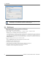
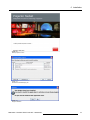

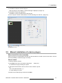

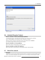
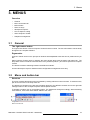


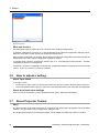

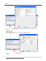
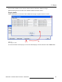
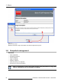
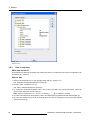
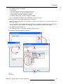

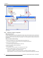
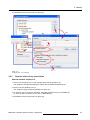


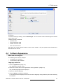
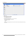


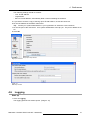


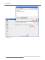

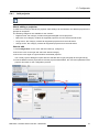


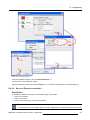
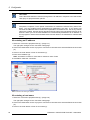
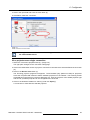
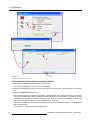
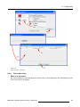


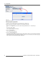
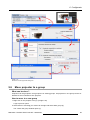

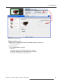


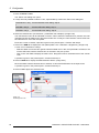


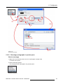


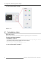
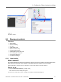
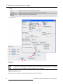
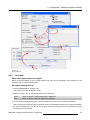
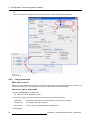
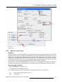
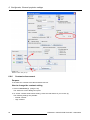
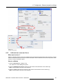
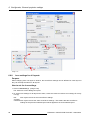

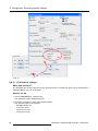
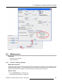
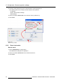


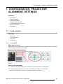
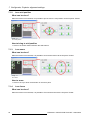
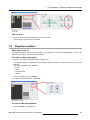

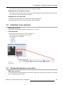
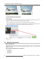
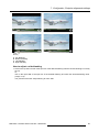
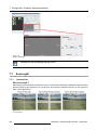
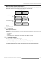

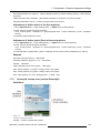


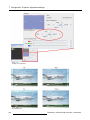
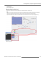


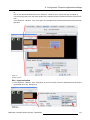
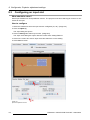
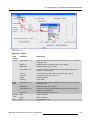

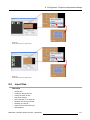
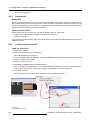
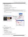
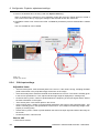
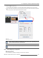
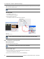
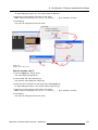

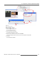
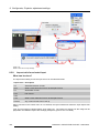

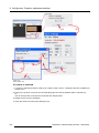
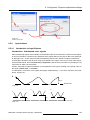
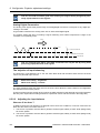

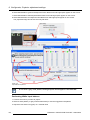
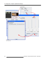
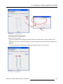
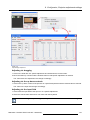
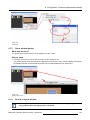


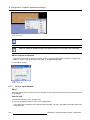

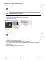


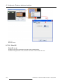

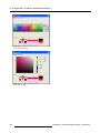
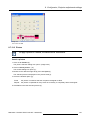
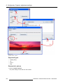

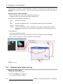

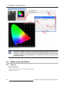

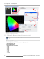
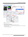


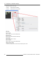

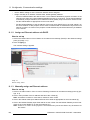


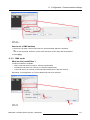
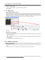


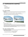
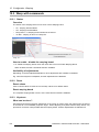

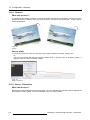
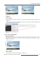

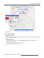
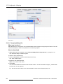
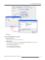
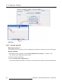
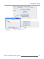

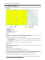
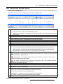
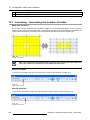
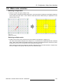

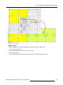
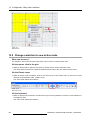

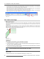
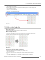
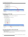

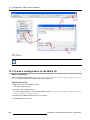

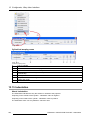

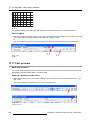
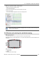
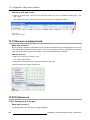

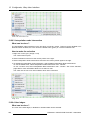


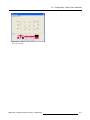

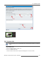
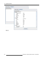
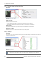
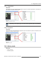
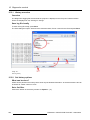


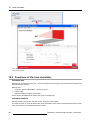
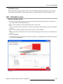
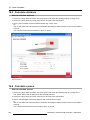


![FLM HD18 [v08]](http://vs1.manualzilla.com/store/data/005664321_1-9e0d84f2b9cac33a4ebfb5904f0dafa1-150x150.png)