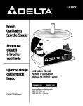
1
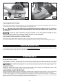
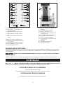
31-300
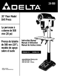
6" Belt/12" Disc
Sanding Center
Courroie de 152,4
mm (6 po)/Disque
de 304,8 mm (12
po) Module de
ponçage
Banda de
152 mm (6") /
disco de 304,
8 mm (12")
Centro de lijado
Instruction Manual
Manuel d’utilisation
Manual de instrucciones
FRANÇAIS (21)
ESPAÑOL (40)
www.deltamachinery.com
(800) 223-7278 - US
(800) 463-3582 - CANADA
A21491 - 02-05-07
Copyright © 2007 Delta Machinery
TABLE OF CONTENTS
IMPORTANT SAFETY INSTRUCTIONS ....................2
SAFETY GUIDELINES - DEFINITIONS .....................2
GENERAL SAFETY RULES .......................................3
ADDITIONAL SPECIFIC SAFETY RULES ................4
FUNCTIONAL DESCRIPTION ...................................7
CARTON CONTENTS ...............................................7
ASSEMBLY .................................................................8
OPERATION ...............................................................12
TROUBLESHOOTING ................................................18
MAINTENANCE ..........................................................18
SERVICE .....................................................................19
ACCESSORIES...........................................................20
WARRANTY ................................................................20
FRANÇAIS ..................................................................21
ESPAÑOL ....................................................................40
IMPORTANT SAFETY INSTRUCTIONS
Read and understand all warnings and operating instructions before using any tool
or equipment. When using tools or equipment, basic safety precautions should always be followed
to reduce the risk of personal injury. Improper operation, maintenance or modification of tools or
equipment could result in serious injury and property damage. There are certain applications for which
tools and equipment are designed. Delta Machinery strongly recommends that this product NOT be modified and/or
used for any application other than for which it was designed.
If you have any questions relative to its application DO NOT use the product until you have written Delta Machinery and
we have advised you. Contact us online at www.deltamachinery.com or by mail at Technical Service Manager, Delta
Machinery, 4825 Highway 45 North, Jackson, TN 38305. In Canada,125 Mural St. Suite 300, Richmond Hill, ON, L4B 1M4)
Information regarding the safe and proper operation of this tool is available from the following sources:
• Power Tool Institute, 1300 Sumner Avenue, Cleveland, OH 44115-2851or online at www.powertoolinstitute.org
• National Safety Council, 1121 Spring Lake Drive, Itasca, IL 60143-3201
• American National Standards Institute, 25 West 43rd Street, 4 floor, New York, NY 10036 www.ansi.org - ANSI 01.1
Safety Requirements for Woodworking Machines
• U.S. Department of Labor regulations www.osha.gov
SAVE THESE INSTRUCTIONS!
SAFETY GUIDELINES - DEFINITIONS
It is important for you to read and understand this manual. The information it contains relates to protecting YOUR SAFETY
and PREVENTING PROBLEMS. The symbols below are used to help you recognize this information.
Indicates an imminently hazardous situation which, if not avoided, will result in death or serious
injury.
Indicates a potentially hazardous situation which, if not avoided, could result in death or serious
injury.
Indicates a potentially hazardous situation which, if not avoided, may result in minor or moderate
injury.
Used without the safety alert symbol indicates a potentially hazardous situation which, if not avoided,
may result in property damage.
CALIFORNIA PROPOSITION 65
Some dust created by power sanding, sawing, grinding, drilling, and other construction activities
contains chemicals known to cause cancer, birth defects or other reproductive harm. Some
examples of these chemicals are:
• lead from lead-based paints,
• crystalline silica from bricks and cement and other masonry products, and
• arsenic and chromium from chemically-treated lumber.
Your risk from these exposures varies, depending on how often you do this type of work. To reduce your
exposure to these chemicals: work in a well ventilated area, and work with approved safety equipment, always
wear NIOSH/OSHA approved, properly fitting face mask or respirator when using such tools.
2
GENERAL SAFETY RULES
Failure to follow these rules may result in serious personal injury.
1.
2.
3.
4.
5.
6.
7.
8.
9.
10.
11.
12.
13.
14. USE THE PROPER EXTENSION CORD. Make sure your
extension cord is in good condition. When using an extension
cord, be sure to use one heavy enough to carry the current
your product will draw. An undersized cord will cause a drop
in line voltage, resulting in loss of power and overheating. See
the Extension Cord Chart for the correct size depending on
the cord length and nameplate ampere rating. If in doubt, use
the next heavier gauge. The smaller the gauge number, the
heavier the cord.
15. SECURE THE WORKPIECE. Use clamps or a vise to hold the
workpiece when practical. Loss of control of a workpiece can
cause injury.
16. FEED THE WORKPIECE AGAINST THE DIRECTION OF
THE ROTATION OF THE BLADE, CUTTER, OR ABRASIVE
SURFACE. Feeding it from the other direction will cause the
workpiece to be thrown out at high speed.
17. DON’T FORCE THE WORKPIECE ON THE MACHINE.
Damage to the machine and/or injury may result.
18. DON’T OVERREACH. Loss of balance can make you fall into
a working machine, causing injury.
19. NEVER STAND ON THE MACHINE. Injury could occur if the tool
tips, or if you accidentally contact the cutting tool.
20. NEVER LEAVE THE MACHINE RUNNING UNATTENDED.
TURN THE POWER OFF. Don’t leave the machine until it comes
to a complete stop. A child or visitor could be injured.
21. TURN THE MACHINE “OFF”, AND DISCONNECT THE
MACHINE FROM THE POWER SOURCE before installing or
removing accessories, changing cutters, adjusting or changing
set-ups. When making repairs, be sure to lock the start switch
in the “OFF” position. An accidental start-up can cause injury.
22. MAKE YOUR WORKSHOP CHILDPROOF WITH
PADLOCKS, MASTER SWITCHES, OR BY REMOVING
STARTER KEYS. The accidental start-up of a machine by a
child or visitor could cause injury.
23. STAY ALERT, WATCH WHAT YOU ARE DOING, AND USE
COMMON SENSE. DO NOT USE THE MACHINE WHEN
YOU ARE TIRED OR UNDER THE INFLUENCE OF DRUGS,
ALCOHOL, OR MEDICATION. A moment of inattention while
operating power tools may result in injury.
24.
USE OF THIS TOOL CAN GENERATE AND
DISBURSE DUST OR OTHER AIRBORNE PARTICLES,
INCLUDING WOOD DUST, CRYSTALLINE SILICA DUST
AND ASBESTOS DUST. Direct particles away from face
and body. Always operate tool in well ventilated area and
provide for proper dust removal. Use dust collection system
wherever possible. Exposure to the dust may cause serious
and permanent respiratory or other injury, including silicosis (a
serious lung disease), cancer, and death. Avoid breathing the
dust, and avoid prolonged contact with dust. Allowing dust to
get into your mouth or eyes, or lay on your skin may promote
absorption of harmful material. Always use properly fitting
NIOSH/OSHA approved respiratory protection appropriate for
the dust exposure, and wash exposed areas with soap and
water.
FOR YOUR OWN SAFETY, READ THE INSTRUCTION
MANUAL BEFORE OPERATING THE MACHINE. Learning
the machine’s application, limitations, and specific hazards
will greatly minimize the possibility of accidents and injury.
WEAR EYE AND HEARING PROTECTION. ALWAYS
USE SAFETY GLASSES. Everyday eyeglasses are NOT
safety glasses. USE CERTIFIED SAFETY EQUIPMENT.
Eye protection equipment should comply with ANSI Z87.1
standards. Hearing equipment should comply with ANSI
S3.19 standards.
WEAR PROPER APPAREL. Do not wear loose clothing,
gloves, neckties, rings, bracelets, or other jewelry which may
get caught in moving parts. Nonslip protective footwear is
recommended. Wear protective hair covering to contain long
hair.
DO NOT USE THE MACHINE IN A DANGEROUS
ENVIRONMENT. The use of power tools in damp or wet
locations or in rain can cause shock or electrocution. Keep
your work area well-lit to prevent tripping or placing arms,
hands, and fingers in danger.
MAINTAIN ALL TOOLS AND MACHINES IN PEAK
CONDITION. Keep tools sharp and clean for best and safest
performance. Follow instructions for lubricating and changing
accessories. Poorly maintained tools and machines can further
damage the tool or machine and/or cause injury.
CHECK FOR DAMAGED PARTS. Before using the machine,
check for any damaged parts. Check for alignment of moving
parts, binding of moving parts, breakage of parts, and any
other conditions that may affect its operation. A guard or any
other part that is damaged should be properly repaired or
replaced with Delta or factory authorized replacement
parts. Damaged parts can cause further damage to the
machine and/or injury.
KEEP THE WORK AREA CLEAN. Cluttered areas and benches
invite accidents.
KEEP CHILDREN AND VISITORS AWAY. Your shop is a
potentially dangerous environment. Children and visitors can be
injured.
REDUCE THE RISK OF UNINTENTIONAL STARTING. Make
sure that the switch is in the “OFF” position before plugging
in the power cord. In the event of a power failure, move the
switch to the “OFF” position. An accidental start-up can cause
injury. Do not touch the plug’s metal prongs when unplugging
or plugging in the cord.
USE THE GUARDS. Check to see that all guards are in place,
secured, and working correctly to prevent injury.
REMOVE ADJUSTING KEYS AND WRENCHES BEFORE
STARTING THE MACHINE. Tools, scrap pieces, and other
debris can be thrown at high speed, causing injury.
USE THE RIGHT MACHINE. Don’t force a machine or an
attachment to do a job for which it was not designed. Damage
to the machine and/or injury may result.
USE RECOMMENDED ACCESSORIES. The use of
accessories and attachments not recommended by Delta
may cause damage to the machine or injury to the user.
3
ADDITIONAL SPECIFIC SAFETY RULES
Failure to follow these rules may result in serious personal injury.
1.
DO NOT OPERATE THIS MACHINE until it is
completely assembled and installed according to
the instructions. A machine incorrectly assembled
can cause serious injury.
2. OBTAIN ADVICE from your supervisor, instructor,
or another qualified person if you are not thoroughly
familiar with the operation of this machine.
Knowledge is safety.
3. FOLLOW ALL WIRING CODES and recommended
electrical connections to prevent shock or electrocution.
4. NEVER TURN THE MACHINE “ON” before
clearing the table/work area of all objects (tools,
scraps of wood, etc.). Flying debris is dangerous.
5. NEVER TURN THE MACHINE “ON” with the workpiece contacting the abrasive surface. Kickback
can occur.
6. SECURE THE MACHINE to a supporting surface. Vibration can cause the machine to slide, walk, or tip
over.
7. COVER THE POWER TAKE-OFF SHAFT when not
using accessories. Unguarded rotating shafts can
create an entanglement hazard which can result in
injury.
8. USE A DUST COLLECTION SYSTEM. Some types
of wood are known to cause disease or other health
problems.
9. CLEAN THE MACHINE and dust collector thoroughly
when processing different types of workpieces
(wood, steel, or aluminum). Combining wood and
metal dust can create an explosion or fire hazard.
DO NOT SAND OR POLISH MAGNESIUM. Fire
will result.
10. PREVENT THE WORKPIECE from contacting the
sanding belt before starting the tool. Loss of control
of the workpiece is dangerous.
11. AVOID AWKWARD OPERATIONS AND HAND
POSITIONS. A sudden slip could cause a hand to
move into the abrasive disc or belt.
12. MAINTAIN A MAXIMUM CLEARANCE OF 1/16"
be-tween the table and the abrasive disc. The
workpiece could be drawn into the space between
the abrasive disc and the table.
13. SUPPORT THE WORKPIECE firmly with a miter
gauge, backstop, or work table when sanding with
a belt. Hold the workpiece firmly. Loss of control of
the workpiece can result in injury.
14. AVOID KICKBACK by sanding in accordance
with the directional arrows. Feed the workpiece
against the downward rotation side of the disc or
the forward rotation of the belt. Loss of control of
the workpiece can result in injury.
15. DO NOT SAND very small or very thin workpieces
that cannot be safely controlled. Loss of control of
the workpiece can result in injury.
16. PROPERLY SUPPORT LONG OR WIDE WORKPIECES. Loss of control of the workpiece is dangerous.
17. NEVER PERFORM LAYOUT, ASSEMBLY, OR SET-UP
WORK on the table/work area when the machine is
running. A sudden slip could cause a hand to move
into the abrasive surface. Severe injury can result.
18. TURN THE MACHINE “OFF”, disconnect the
machine from the power source, and clean the
table/work area before leaving the machine. LOCK
THE SWITCH IN THE “OFF” POSITION to prevent
unauthorized use. Someone else might accidentally
start the machine and cause injury to themselves.
19. ADDITIONALINFORMATION regarding the safe
and proper operation of power tools (i.e. a safety
video) is available from the Power Tool Institute,
1300 Sumner Avenue, Cleveland, OH 44115-2851
(www.powertoolinstitute.com). Information is also
available from the National Safety Council, 1121
Spring Lake Drive, Itasca, IL 60143-3201. Please
refer to the American National Standards Institute
ANSI 01.1 Safety Requirements for Woodworking
Machines and the U.S. Department of Labor OSHA
1910.213 Regulations.
SAVE THESE INSTRUCTIONS.
Refer to them often and use them to instruct others.
4
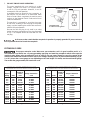
POWER CONNECTIONS
A separate electrical circuit should be used for your machines. This circuit should not be less than #12 wire and should
be protected with a time delay fuse. NOTE: Time delay fuses should be marked “D” in Canada and “T” in the US. If
an extension cord is used, use only 3-wire extension cords which have 3-prong grounding type plugs and matching
receptacle which will accept the machine’s plug. Before connecting the machine to the power line, make sure the
switch (s) is in the “OFF” position and be sure that the electric current is of the same characteristics as indicated on the
machine. All line connections should make good contact. Running on low voltage will damage the machine.
Do not expose the machine to rain or operate the machine in damp locations.
MOTOR SPECIFICATIONS
Your machine is wired for 120/240 volt, 60 HZ alternating current. Before connecting the machine to the power source,
make sure the switch is in the “OFF” position.
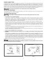
GROUNDING INSTRUCTIONS
This machine must be grounded while in use to protect the operator from electric shock.
1. All grounded, cord-connected machines:
In the event of a malfunction or breakdown, grounding provides a path of least resistance for electric current to
reduce the risk of electric shock. This machine is equipped with an electric cord having an equipment-grounding
conductor and a grounding plug. The plug must be plugged into a matching outlet that is properly installed and
grounded in accordance with all local codes and ordinances.
Do not modify the plug provided - if it will not fit the outlet, have the proper outlet installed by a qualified electrician.
Improper connection of the equipment-grounding conductor can result in risk of electric shock. The conductor with
insulation having an outer surface that is green with or without yellow stripes is the equipment-grounding conductor.
If repair or replacement of the electric cord or plug is necessary, do not connect the equipment-grounding conductor
to a live terminal.
Check with a qualified electrician or service personnel if the grounding instruction are not completely understood, or
if in doubt as to whether the machine is properly grounded.
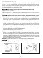
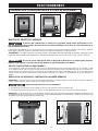
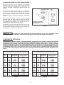
Use only 3-wire extension cords that have 3-prong grounding type plugs and matching 3-conductor receptacles that
accept the machine’s plug, as shown in Fig. A.
Repair or replace damaged or worn cord immediately.
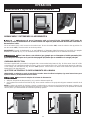
2. Grounded, cord-connected machines intended for use on a supply circuit having a nominal rating less than
150 volts:
If the machine is intended for use on a circuit that has an outlet that looks like the one illustrated in Fig. A, the
machine will have a grounding plug that looks like the plug illustrated in Fig. A. A temporary adapter, which looks like
the adapter illustrated in Fig. B may be used to connect this plug to a matching 2-conductor receptacle as shown
in Fig. B, if a properly grounded outlet is not available. The temporary adapter should be used only until a properly
grounded outlet can be installed by a qualified electrician. The green-colored rigid ear, lug, and the like, extending
from the adapter must be connected to a permanent ground such as a properly grounded outlet box. Whenever the
adapter is used, it must be held in place with a metal screw.
NOTE: In Canada, the use of a temporary adapter is not permitted by the Canadian Electric Code.
In all cases, make certain that the receptacle in question is properly grounded. If you are not sure,
have a qualified electrician check the receptacle.
GROUNDED OUTLET BOX
GROUNDED OUTLET BOX
GROUNDING MEANS
CURRENT
CARRYING
PRONGS
ADAPTER
GROUNDING BLADE
IS LONGEST OF THE 3 BLADES
Fig. A
Fig. B
5
3. 240 VOLT SINGLE PHASE OPERATION
The motor supplied with your machine is a dual
voltage, 120/240 volt motor. It is shipped readyto-run for 120 volt operation. However, it can be
converted for 240 volt operation.
A qualified electrician should do the conversion, or
the machine can be taken to an Authorized Delta
Service Center. When completed, the machine must
conform to the National Electric Code and all local
codes and ordinances.
The machine is converted by re-wiring the motor
for 240 volts, installing a 240 volt plug on the power
supply cord and replacing the switch with one that is
rated for 240 volt operation.
Be sure the 240 volt plug is only used in an outlet
having the same configuration as the plug illustrated
in Fig. C. No adapter should be used with the 240
volt plug.
GROUNDED OUTLET BOX
CURRENT
CARRYING
PRONGS
GROUNDING BLADE
IS LONGEST OF THE 3 BLADES
Fig. C
In all cases, make certain that the receptacle in question is properly grounded. If you are not sure,
have a qualified electrician check the receptacle.
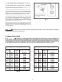
EXTENSION CORDS
Use proper extension cords. Make sure your extension cord is in good condition and is a 3wire extension cord which has a 3-prong grounding type plug and matching receptacle which will accept the
machine’s plug. When using an extension cord, be sure to use one heavy enough to carry the current of the
machine. An undersized cord will cause a drop in line voltage, resulting in loss of power and overheating. Fig. D1 or D-2, shows the correct gauge to use depending on the cord length. If in doubt, use the next heavier gauge.
The smaller the gauge number, the heavier the cord.
MINIMUM GAUGE EXTENSION CORD
MINIMUM GAUGE EXTENSION CORD
RECOMMENDED SIZES FOR USE WITH STATIONARY ELECTRIC MACHINES
RECOMMENDED SIZES FOR USE WITH STATIONARY ELECTRIC MACHINES
Ampere
Rating
0-6
0-6
0-6
0-6
6-10
6-10
6-10
6-10
10-12
10-12
10-12
10-12
12-16
12-16
12-16
Volts
120
120
120
120
120
120
120
120
120
120
120
120
120
120
120
Total
Length of
Cord in
Feet
up to 25
25-50
50-100
100-150
up to 25
25-50
50-100
100-150
up to 25
25-50
50-100
100-150
up to 25
25-50
Ampere
Gauge of Extension
Cord
18 AWG
16 AWG
16 AWG
14 AWG
18 AWG
16 AWG
14 AWG
12 AWG
16 AWG
16 AWG
14 AWG
12 AWG
14 AWG
12 AWG
Rating
0-6
0-6
0-6
0-6
6-10
6-10
6-10
6-10
10-12
10-12
10-12
10-12
12-16
12-16
12-16
GREATER THAN 50 FEET NOT RECOMMENDED
Fig. D-1
Volts
240
240
240
240
240
240
240
240
240
240
240
240
240
240
240
Total
Length of
Cord in
Feet
up to 50
50-100
100-200
200-300
up to 50
50-100
100-200
200-300
up to 50
50-100
100-200
200-300
up to 50
50-100
GREATER THAN 50 FEET NOT RECOMMENDED
Fig. D-2
6
Gauge of Extension
Cord
18 AWG
16 AWG
16 AWG
14 AWG
18 AWG
16 AWG
14 AWG
12 AWG
16 AWG
16 AWG
14 AWG
12 AWG
14 AWG
12 AWG
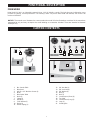
FUNCTIONAL DESCRIPTION
FOREWORD
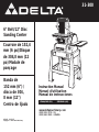
Delta Model 31-300 is an industrial/commercial duty 1-1/2 HP belt/disc sander. The induction-type, ball-bearing motor
provides long-lasting, smooth performance. The Sanding Center can provide 3000 SFPM with the belt, and the disc will
revolve at 2100 RPM.
NOTICE: The manual cover illustrates the current production model. All other illustrations contained in the manual are
representative only and may not depict the actual labeling or accessories included. These are intended to illustrate
technique only.
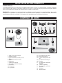
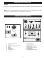
CARTON CONTENTS
6
2
3
10
9
4
8
7
12
11
15
13
14
16
1
18
17
19
5
20
21
1.
2.
3.
4.
5.
6.
7.
8.
9.
10.
11.
Disc Sander Table
Belt Guard
#10-32 x 1/2" Machine Screws (4)
Motor
Belt Sander Table
Knob (2)
Clamp (2)
Handle (1)
7/16” Washer (2)
Spring (2)
Tension Spring (1)
12.
13.
14.
15.
16.
17.
18.
19.
20.
21.
7
3/8” Hex Nut (1)
3/8” Lock Nut (1)
3/8” Washer (1)
Stud (2)
Stud (1)
Lower Braces (Short) (2)
Top Shelf
Lower Braces (Long) (2)
Legs (4)
Sanding Disc
22
30
23
31
39
24
32
25
33
26
34
27
35
28
36
29
37
38
For stand assembly:
For attaching the motor to the stand:
22.
23.
24.
25.
30.
31.
32.
33.
34.
35.
36.
37.
38.
39.
5/16-18 x 5/8"Carriage Bolt (32)
5/16" Lock Washer (32)
5/16" Flat Washer (32)
5/16"-18 Hex nut (32)
For attaching the center to the stand
26.
27.
28.
29.
5/16 x 1/2" Hex Head Bolt (4)
5/16" Lock Washer (4)
#10-32 x 1/2" Machine Screws (4)
#10 Flat Washers (4)
1/2" Flat Washer (2)
1/2" Locknut (2)
1/2-13 x 3/4" Hex Head Bolt (2)
5/16" Lock Washer (2)
5/16" Flat Washer (2)
5/16" Wing Nut (2)
5/16-18 x 1" Carriage Head Bolt (2)
Pointer
#10-32 Round Head Screw
Sanding Center
UNPACKING AND CLEANING
Carefully unpack the machine and all loose items from the shipping container(s). Remove the rust-preventative oil from
unpainted surfaces using a soft cloth moistened with mineral spirits, paint thinner or denatured alcohol.
Do not use highly volatile solvents such as gasoline, naphtha, acetone or lacquer thinner for cleaning your
machine.
After cleaning, cover the unpainted surfaces with a good quality household floor paste wax.
ASSEMBLY
For your own safety, do not connect the machine to the power source until the machine is
completely assembled and you read and understand the entire instruction manual.
ASSEMBLY TOOLS REQUIRED
Phillips Head Screwdriver (not supplied)
11/16”, 3/4”, and 1/2” Socket or Open End Wrenches (not supplied)
ASSEMBLY TIME ESTIMATE
Assembly for this machine takes approximately one to two hours.
8
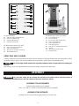
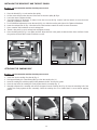
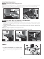
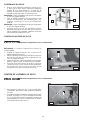
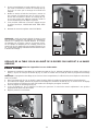
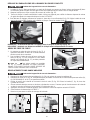
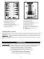
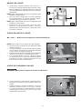
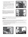
ASSEMBLING THE STAND
1.
Use sixteen 5/8" carriage bolts, flat washers,
lockwashers, and hex nuts to attach two short lower
braces (A) Fig. 1 and two long lower braces (B) to the
four legs (C).
D
C
NOTE: Hand tighten the hex nuts for fufther adjustments.
2.
Use the remaining carriage bolts, flat washers,
lockwashers, and hex nuts to attach the top shelf (D)
to the legs.
A
B
NOTE: Hand tighten the hex nuts for future adjustments.
3.
Make sure that the stand is on level ground. Use a
helper to lift and position the machine on the top shelf.
Tighten all stand hardware securely.
Fig. 1
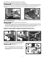
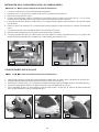
ATTACHING THE MOTOR TO THE STAND
Disconnect the machine from the power source!
NOTE: The motor comes with an attachment bracket
installed.
1.
2.
3.
4.
C
Locate the welded bracket (A) Fig. 2 underneath the
top shelf of the stand.
Align the holes in the motor attachment bracket (B)
with the holes in the welded bracket (A).
Insert the hex head bolts and flat washers (C) in the
holes from the inside out.
Use an 11/16" open-end wrench to tighten the
locknuts (D) on the hex head bolts. Keep the hex head
bolts from turning with an 11/16" socket wrench.
B
D
A
Fig. 2
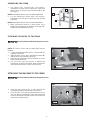
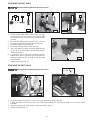
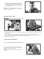
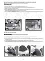
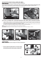
ATTACHING THE MACHINE TO THE STAND
Disconnect the machine from the power source!
1.
2.
Push the motor belt (A) Fig. 3 down through the
rectangular hole (B) in the top shelf of the stand.
Use four 5/16" x 1/2" bolts and lockwashers (C) Fig. 3
and four #10-32 self-tapping screws and washers (D)
to fasten the machine to the top shelf. (The motor was
removed for easier viewing.)
C
B
D
Fig. 3
9
A
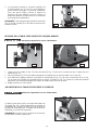
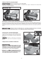
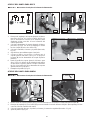
INSTALLING THE DRIVE BELT AND THE BELT GUARD
Disconnect the machine from the power source!
1.
2.
3.
4.
5.
6.
7.
8.
9.
Place the belt (A) Fig. 4 on the sander drive pulley.
Lift the motor and place the other end of the belt on the motor pulley (B) Fig.4.
Lower the motor to tighten the belt.
Check the pulleys for alignment. To adjust, loosen the set screw (E) Fig. 4 with a 3/16" hex wrench to move the motor
pulley (B). Tighten the set screw.
For an additional adjustment, loosen the nuts (D) Fig. 4 to slide the sanding unit right or left. Tighten all hardware.
Insert the carriage bolts (C) Fig. 4 from the inside of the bracket to attach the motor to motor the mounts.
Place a washer and lockwasher on each carriage bolt.
Thread a wing nut (I) on each carriage bolt and tighten securely.
Place the belt guard (F) Fig. 5 over pulley and belt. Align the holes in the guard (G) with the holes in the shelf (H). Fasten
the guard to the shelf with four #10-32 machine screws.
A
F
C
D
I
I
H
G
B
E
Fig. 4
Fig. 5
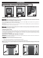
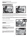
ATTACHING THE SANDING DISC
Disconnect the machine from the power source!
1.
2.
3.
4.
5.
Clean and dry the sanding disc plate (A) Fig. 6.
Peel approximately 1/2 of the backing (B) Fig. 6 from the sanding disc (C).
Insert the sanding disc with the paper backing between the disc and the disc guard.
Press the top half of the sanding disc firmly against the disc assembly (Fig. 7).
Manually rotate the disc assembly and remove the paper from the sanding disc (Fig. 8). Press the remaining half of the
sanding disc firmly against the disc assembly. Check the sanding disc to be certain that it is secure before applying
power.
A
B
C
Fig. 6
Fig. 7
10
Fig. 8
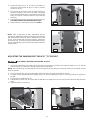
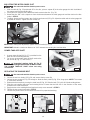
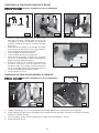
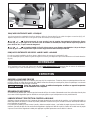
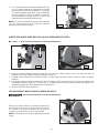
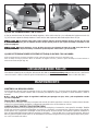
ATTACHING THE DISC TABLE
Disconnect the machine from the power source!
E
C
D
A
A
B
B
Fig.9
1.
2.
3.
4.
5.
6.
7.
A
Fig. 11
Fig. 10
C
C
B
Thread the disc table trunnion stud (A) Figs. 9 & 10 in
the hole (B) Fig. 10 on the side of the machine. (This
stud is listed as No. 15 in the carton contents). Tighten
securely.
Place the disc table trunnion clamp (C) Figs. 9 & 10 on
the stud. Insert the two pins (D) in the two holes (E).
Attach the washer, spring, and knob.
Follow the same procedure for the other side.
Place the table in position. Rest the table trunnion
(A) Fig. 11 in the groove (B) of the attaching clamps.
Tighten the knob (C)
Locate the scale on the trunnion.Remove the disc
table trunnion knob (C) from tha side of the machine.
Attach the pointer (A) Fig. 12 at (B) on the disc table
trunnion clamp.
Replace the knob (C) Fig. 11.
A
Fig. 12
B
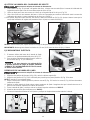
ATTACHING THE BELT TABLE
Disconnect the machine from the power source!
B
D
E
C
A
Fig. 14
Fig. 13
1.
2.
3.
Insert the trunnion key (A) Fig. 13 in the slot on the side of the sanding arm (B).
Thread the stud (C) into the hole (D) on the side of the sanding arm. (This stud is listed as no. 16 in the carton
contents).
Attach the washer, nut, lever, spring, and locknut (Inset - Fig 14)
4.
Tighten the lever (E) Fig.14.
11
OPERATION
OPERATIONAL CONTROLS AND ADJUSTMENTS
A
A
A
Fig. 16
Fig. 17
Fig. 18
STARTING AND STOPPING THE MACHINE
Make sure that the switch is in the “OFF” position before plugging the cord into the outlet. Do not touch the
plug’s metal prongs when unplugging or plugging in the cord.
The on-off switch (A) Fig. 16 is located on the sander base. To turn the sander “ON”, move the switch to the up position. To
turn the sander “OFF”, move the switch to the down position.
IMPORTANT: When the machine is not in use, the switch should be locked in the "OFF" position to prevent unauthorized use,
using a padlock (A) Fig. 17 with a 3/16" diameter shackle.
In the event of a power outage (such as a breaker or fuse trip), always move the switch to the “OFF”
position until the main power is restored.
OVERLOAD PROTECTION
The motor supplied with your sander is equipped with a reset overload relay button (A) Fig. 18. If the motor shuts off or fails
to start because of overloading (sanding too heavy, using a worn sanding belt or disc, using the sander beyond its capacity),
or low voltage, turn the switch (A) Fig. 16 to the “OFF” position. Let the motor cool three to five minutes and push the reset
button (A) Fig. 18. Start the motor.
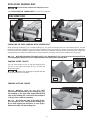
ADJUSTING THE TENSION AND TRACKING OF THE BELT
IMPORTANT: The machine is shipped without belt tension. Before operating the machine, follow these instructions for
adjusting the belt for tension and tracking.
Disconnect the machine from the power source!
1.
Loosen the two lock knobs (B) Fig. 19, and remove the top cover (A).
2.
Turn the belt tension lever (C) Fig. 20 counter-clockwise to increase the belt tension.
NOTE: The tension lever (C) is spring-loaded and can be repositioned by pulling out the handle, moving it, and letting it spring
back into position. Correct tension is determined by (1) flatness of the belt on the plate and (2) slippage of the belt when
sanding heavy work.
B
E
C
A
Fig. 19
Fig. 20
12
3.
Rotate the belt (D) Fig. 21 by hand, and tighten or
loosen the tracking knob (E) Figs. 20 and 21 until the
tracking is correct.
4.
Turn the tool on and off to check for proper tracking. If
the belt is leading to one side or the other, very gently
turn the tracking knob (E) Fig. 20 clockwise to move the
belt to the right or counter-clockwise to move the belt
to the left.
5.
A final adjustment can be made with the motor running.
THIS ADJUSTMENT SHOULD BE VERY SLIGHT.
6.
Replace the top cover that was removed in STEP 1.
E
D
Fig. 21
NOTE: After a long period of time, adjustments may be
necessary to maintain the tension and tracking of the sanding
belt. If the belt will not hold its tension, tighten the set screw
(G) Fig. 22. If the belt will not hold its tracking, tighten the
set screw (F) Fig. 22. Make only small adjustments to these
screws. Over-tightening will lock the tension lever and/or the
tracking knob.
F
G
Fig. 22
ADJUSTING THE SANDING BELT TABLE 90° TO THE BELT
DISCONNECT MACHINE FROM POWER SOURCE.
1.
Loosen the table tilting lock handle (A) Fig. 23. Move the stop (B) into position and rotate the table (C) Fig. 24 until the
trunnion (D) Fig. 23 contacts the stop (B). Tighten the lock handle (A).
NOTE: The lock handle (A) is spring-loaded and can be repositioned by pulling out the handle, moving it, and letting it spring
back into position.
2.
3.
4.
5.
6.
Place a square (E) Fig. 24 on the table against the belt to check the angle of the table to the belt.
To adjust, loosen the table-tilting lock handle (A) Fig. 23. Turn the adjusting screw (F) in or out until table is 90° degrees to
the belt.
Tighten the lock handle (A) Fig. 23.
The adjusting screw (F) Fig. 23 ensures that the belt table can rapidly return to the correct position after the table has been
tilted.
Adjust the pointer, if necessary.
F
E
A
C
Fig. 23
D
B
Fig. 24
13
TILTING THE BELT SANDER TABLE
Disconnect the machine from the power source.
You can tilt the table (A) Fig. 25 down to 45 °. To tilt the table, loosen the lock handle (B). Note the degree of tilt on the
pointer and scale. Stop (E) Fig. 26 can be positioned for 45° or 40° by turning the screw (F) to adjust the angle.
NOTE: When tilting the table, rotate the stop (E) Fig. 26 out of the way.
B
C
D
A
E
F
Fig. 25
Fig. 26
ADJUSTING THE MITER GAUGE SLOT PARALLEL TO THE SANDING BELT
Disconnect the machine from the power source.
1.
2.
Position the table (A) (Figs. 27 and 28) 90° degrees to the belt. Place a square (B) in the miter gauge slot with the
blade (C) of the square touching the sanding belt. Check the opposite end of the belt to see if the miter gauge slot
(D) is parallel to the belt.
To adjust, loosen the three (3) screws (E) Fig. 29, located underneath the table. After adjustment, tighten the three
screws (E).
NOTE: When making this adjustment, tighten the table lock handle.
IMPORTANT: Maintain a maximum distance of 1/16" between the sanding belt and the table.
C
B
C
E
A
B
A
D
D
Fig. 27
Fig. 29
Fig. 28
CHANGING THE POSITION OF THE SANDING ARM
Disconnect the machine from the power source.
C
D
E
1. You can use the sanding arm (A) in the vertical position
(Fig. 31), the horizontal position (Fig. 30), or any angle in
between. Loosen the lock handle (B) Fig. 30, position the
arm (A) to the desired angle, and tighten the lock handle
(B).
B
A
Fig. 30
14
2.
C
Remove the top idler pulley cover (C) Figs. 30 and
31 when sanding in the horizontal position. For a
long workpiece, lower the deflector plate (D) Fig.
30. For a short workpiece, raise the deflector plate
(D) to deflect saw dust.
A
NOTE: With the sanding arm (A) in the horizontal
position (Fig. 30), use the table (E) or the accessory
backstop to support the work.
E
B
Fig. 31
ADJUSTING THE DISC TABLE
Disconnect the machine from the power source.
E
F
A
B
Fig. 32
Fig. 33
1. Loosen the lock handle (A) Fig. 32. Move the table (B) Fig. 33 until the it contacts the stop. Tighten the lock
handle (A) Fig. 32.
2. Place a square (E) Fig. 33 on the table and against the sanding disc to see if the table is 90° to the disc.
3. To adjust, loosen the lock handle (A) Fig. 32. Tighten or loosen the screw (F) Fig. 32 until the angle is 90.° The
stop (F) Fig. 32 ensures that the table can rapidly return to the correct angle.
5. Adjust pointer, if necessary.
TILTING THE DISC SANDER TABLE
Disconnect the machine from the power source.
You can tilt the table (A) 45 ° degrees down (Fig. 34)
by loosening the lock handle (B). The degree of tilt is
determined by the scale and pointer.
Fig. 33
B
NOTE: Ensure that the lock handle is tight before using
the sander.
A
°
Fig. 34
15
ADJUSTING THE MITER GAUGE SLOT
Disconnect the machine from the power source.
1.
2.
3.
4.
With the table (A) Fig. 35 positioned 90° to the disc, place a square (B) in the miter gauge slot with the blade of
the square touching the sanding disc.
Use a pencil to mark the place where the blade contacts the disc. (Fig. 35).
Rotate the disc 180.° Use a square to check the distance between the miter gauge slot and the mark on the disc
made in STEP 3.
To adjust, loosen the four screws, two of which are shown at (D) Fig. 36. Adjust the table until the miter gauge slot
is parallel to the disc. Tighten the four screws (D).
B
D
A
A
Fig. 35
Fig. 36
NOTE: When making this adjustment, tighten the lock handle (A) Fig. 36.
IMPORTANT: Maintain a maximum distance of 1/16" between the sanding disc and the table.
POWER TAKE-OFF SHAFT
A
1.
2.
A power take-off shaft (A) Fig. 37 is provided on the
lower end of the sanding belt arm.
For access to the power take-off shaft, remove the
two screws (B) Fig. 37, and cover (C).
B
Unguarded rotating shafts (A) Fig 37
can create an entanglement hazard. ALWAYS COVER
THE POWER TAKE-OFF SHAFT when not using
accessories.
C
Fig. 37
REPLACING THE SANDING BELT
Disconnect the machine from the power source.
1.
2.
3.
4.
5.
6.
7.
Loosen the two lock knobs (A) Fig. 38, and remove the top cover (B).
Loosen the two screws (C) Fig. 39 enough to allow the back panel (D) Fig. 38 to hinge open. NOTE: The screws
(C) cannot be removed.
Release the belt tension by turning the hand lever (E) Fig. 38. Slide the belt (F) Fig. 40 off of both sanding drums.
Slide the new sanding belt over both sanding drums. Ensure that the belt runs in the direction of the arrow,
printed on the inside of the belt.
Apply tension to the sanding belt and replace the top cover removed in STEP 2.
Tighten the two screws loosened in STEP 3.
Connect the power source to the sander and check for proper belt tracking.
B
E
A
F
C
D
Fig. 39
Fig. 38
16
Fig.40
REPLACING SANDING DISC
Disconnect the machine from the power source.
See “ATTACHING THE SANDING DISC” section in this manual.
MACHINE USE
A
A
B
Fig.41
Fig.42
SURFACING OR EDGE SANDING WITH SANDING BELT
When surfacing sanding (Fig. 41) or edge sanding (Fig. 42), place the sanding arm in the horizontal position. Use the
table (A) to keep the workpiece in place. Hold the workpiece firmly and keep your fingers away from the sanding belt.
Place the end of the workpiece against the table. Move the the workpiece evenly across the sanding belt. Apply only
enough pressure to allow the sanding belt to remove material. Use extra caution when sanding very thin pieces.
Position the edge of the table (A) Fig. 41 a maximum of 1/16" away from the sanding belt (B) to
avoid trapping the workpiece or your fingers between the table and the sanding belt.
SANDING INSIDE CURVES
A
You can sand inside curves on the top sanding drum
(Fig. 43) if you loosen the knobs (A) Fig. 43 inset and
remove the guard
Replace the sanding drum guard after the
sanding operation is completed.
Fig.43
SANDING OUTSIDE CURVES
B
Always sand on the left SIDE
(downward ROTATION side) of the sanding disc (Fig.
44). Sanding on the right SIDE (upward ROTATION
side) of the sanding disc could cause the workpiece
to fly up, which could be hazardous.
Position the edge of the table (A) Fig.
44 a maximum of 1/16" away from the sanding disc
(B) to avoid trapping the workpiece or your fingers
between the table and the sanding disc.
A
Fig.44
17
B
C
A
Fig.46
Fig.45
END SANDING WITH THE DISC
When sanding the ends of narrow workpieces, use the sanding disc and an accessory miter gauge (A) Fig. 45. Move
the work from the center to the left side (downward) of the sanding disc.
Always sand on the left SIDE (downward ROTATION side) of the sanding disc (Fig. 45). Sanding on
the right SIDE (upward ROTATION side) of the sanding disc could cause the workpiece to fly up, which could
be hazardous.
Position the edge of the table (C) Fig. 45 a maximum of 1/16" away from the sanding disc (B) to
avoid trapping the workpiece or your fingers between the table and the sanding disc.
END SANDING WIDE WORKPIECES WITH THE BELT
When sanding the ends of wide workpieces, use the sanding arm in the vertical position (Fig. 46).
For more accurate work, use an accessory miter gauge and move the work evenly across the sanding belt (Fig. 46).
TROUBLESHOOTING
For assistance with your machine, visit our website at www.deltamachinery.com for a list of service centers or call the
DELTA Machinery help line at 1-800-223-7278 (In Canada call 1-800-463-3582).
MAINTENANCE
KEEP MACHINE CLEAN
Periodically blow out all air passages with dry compressed air. All plastic parts should be cleaned with a soft damp
cloth. NEVER use solvents to clean plastic parts. They could possibly dissolve or otherwise damage the material.
Wear certified safety equipment for eye, hearing and respiratory protection while using compressed air.
FAILURE TO START
Should your machine fail to start, check to make sure the prongs on the cord plug are making good contact in the
outlet. Also, check for blown fuses or open circuit breakers in the line.
LUBRICATION & RUST PROTECTION
Apply household floor paste wax to the machine table, extension table or other work surface weekly. Or use a commercially
available protective product designed for this purpose. Follow the manufacturer’s instructions for use and safety.
To clean cast iron tables of rust, you will need the following materials: a sheet of medium Scotch-Brite™ Blending Hand
Pad, a can of WD-40® and a can of degreaser. Apply the WD-40 and polish the table surface with the Scotch-Brite pad.
Degrease the table, then apply the protective product as described above.
18
SERVICE
REPLACEMENT PARTS
Use only identical replacement parts. For a parts list or to order parts, visit our website at servicenet.deltamachinery.com. You
can also order parts from your nearest factory-owned branch, or by calling our Customer Care Center at 1-800-223-7278 to
receive personalized support from highly-trained technicians.
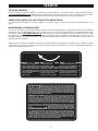
FREE WARNING LABEL REPLACEMENT
If your warning labels become illegible or are missing, call 1-800-223-7278 for a free replacement.
UNGUARDED ROTATING SHAFTS
CAN CREATE AN ENTANGLEMENT
HAZARD WHICH CAN RESULT IN
INJURY. ALWAYS MAKE CERTAIN
THAT THE SPINDLE COVER IS IN
PLACE WHEN MACHINE IS NOT
BEING USED WITH
ACCESSORIES.
LOS EJES GIRATORIOS
DESPROTEGIDOS PUEDEN
PRODUCIR UN RIESGO DE ENREDO
Y PROVOCAR LESIONES. SIEMPRE
ASEGÚRESE DE QUE LA CUBIERTA
DEL HUSILLO ESTÉ EN SU LUGAR
CUANDO LA MÁQUINA NO SE
UTILIZA CON LOS ACCESORIOS.
DES ARBRES TOURNANTS NON
PROTÉGÉS PEUVENT PROVOQUER UN
RISQUE D’ENCHEVÊTREMENT QUI
PEUT ENTRAÎNER UNE BLESSURE.
TOUJOURS S’ASSURER QUE LE CAPOT
DE LA BROCHE EST EN POSITION
LORSQUE LA MACHINE N’EST PAS
UTILISÉE AVEC DES ACCESSOIRES.
TO REDUCE THE RISK OF INJURY USER MUST READ THE INSTRUCTION MANUAL BEFORE
OPERATING SANDER OR FINISHING MACHINE. ALWAYS WEAR PROPER EYE AND RESPIRATORY
PROTECTION. WHEN OPERATING THIS TOOL, DO NOT WEAR GLOVES, NECKTIES, JEWELRY, LOOSE CLOTHING OR LONG HAIR.
MAINTAIN 1/16” (1.6 MM) MAXIMUM CLEARANCE BETWEEN TABLE AND SANDING BELT OR DISC. KICKBACK HAZARD. REFER
TO MANUAL ON HOW TO AVOID KICKBACKS ON SANDING BELT AND DISC. KEEP HANDS AWAY FROM ABRASIVE SURFACES. ALWAYS
SUPPORT WORKPIECE WITH MITER GAGE, BACKSTOP OR WORK TABLE. DO NOT OPERATE WHILE UNDER INFLUENCE OF DRUGS,
ALCOHOL OR MEDICATION. SHOCK HAZARD. DO NOT EXPOSE TO RAIN OR USE IN DAMP LOCATIONS. DISCONNET MACHINE FROM
POWER SOURCE BEFORE MAKING REPAIRS OR ADJUSTMENTS.
PARA REDUCIR EL RIESGO DE LESIONES, EL USUARIO DEBE LEER EL MANUAL DE
INSTRUCCIONES ANTES DE USAR LA LIJADORA O MÁQUINA DE LIJADO. UTILICE
SIEMPRE PROTECCIÓN RESPIRATORIA Y VISUAL ADECUADA. CUANDO OPERE LA HERRAMIENTA, NO USE GUANTES, CORBATAS,
JOYAS, ROPA HOLGADA NI EL CABELLO LARGO. MANTENGA UNA DISTANCIA MÁXIMA DE 1,6 MM (1/16”) ENTRE LA MESA Y EL DISCO
O LA BANDA DE LIJADO. RIESGO DE RETROCESO. CONSULTE EL MANUAL PARA SABER CÓMO EVITAR LOS RETROCESOS DEL DISCO
Y LA BANDA DE LIJADO. MANTENGA LAS MANOS LEJOS DE LAS SUPERFICIES ABRASIVAS. SOSTENGA SIEMPRE LA HERRAMIENTA
CON UN CALIBRE INGLETADOR O UN TOPE DE RETENCIÓN O SOBRE UNA MESA DE TRABAJO. NO OPERE LA HERRAMIENTA BAJO
LA INFLUENCIA DE DROGAS, ALCOHOL O MEDICACIÓN. RIESGO DE DESCARGA ELÉCTRICA. NO EXPONGA A LA LLUVIA NI UTILICE
EN LUGARES HÚMEDOS DESCONECTE LA MÁQUINA DE LA FUENTE DE ALIMENTACIÓN ANTES DE REALIZAR REPARACIONES O
AJUSTES.
POUR RÉDUIRE LE RISQUE DE BLESSURE, L’UTILISATEUR DOIT LIRE LE MODE
D’EMPLOI AVANT D’UTILISER LA PONCEUSE OU APPAREIL DE PONÇAGE.
TOUJOURS PORTER UNE PROTECTION OCULAIRE ET UNE PROTECTION RESPIRATOIRE ADÉQUATES. LORS DE L’UTILISATION DE
L’OUTIL, NE PAS PORTER DE GANTS, DE CRAVATES, DE BIJOUX NI DE VÊTEMENTS AMPLES; COUVRIR LES CHEVEUX LONGS. MAINTENIR
UN DÉGAGEMENT MAXIMAL DE 1,6 MM (1/16 PO) ENTRE LA TABLE ET LA COURROIE ET LE DISQUE ABRASIFS. RISQUE DE REBOND.
SE REPORTER AU MODE D’EMPLOI POUR LA PRÉVENTION DE L’EFFET DE REBOND DE LA PONCEUSE À COURROIE ET À DISQUE.
ÉLOIGNER LES MAINS DES SURFACES ABRASIVES. TOUJOURS SOUTENIR LA PIÈCE AVEC LE GUIDE D’ONGLET, LA BUTÉE ANTIRETOUR
OU LA TABLE DE TRAVAIL. NE PAS UTILISER SOUS L’EMPRISE DE DROGUES, D’ALCOOL OU DE MÉDICAMENT. RISQUE DE CHOC
ÉLECTRIQUE. PROTÉGER DE LA PLUIE ET NE PAS UTILISER DANS DES ENDROITS HUMIDES. DÉBRANCHER LA MACHINE DE LA
SOURCE D’ALIMENTATION AVANT DE PROCÉDER À DES RÉGLAGES OU À DES RÉPARATIONS.
SERVICE AND REPAIRS
All quality tools will eventually require servicing and/or replacement of parts. For information about Delta Machinery, its factoryowned branches, or an Authorized Warranty Service Center, visit our website at www.deltamachinery.com or call our Customer
Care Center at 1-800-223-7278. All repairs made by our service centers are fully guaranteed against defective material and
workmanship. We cannot guarantee repairs made or attempted by others.
You can also write to us for information at Delta Machinery, 4825 Highway 45 North, Jackson, Tennessee 38305 - Attention:
Product Service. Be sure to include all of the information shown on the nameplate of your tool (model number, type, serial number,
etc.)
19
ACCESSORIES
A complete line of accessories is available from your Delta Supplier, Porter-Cable • Delta Factory Service Centers, and
Delta Authorized Service Stations. Please visit our Web Site www.deltamachinery.com for a catalog or for the name of
your nearest supplier.
Since accessories other than those offered by Delta have not been tested with this product, use
of such accessories could be hazardous. For safest operation, only Delta recommended accessories should be
used with this product.
WARRANTY
To register your tool for warranty service visit our website at www.deltamachinery.com.
Two Year Limited New Product Warranty
Delta will repair or replace, at its expense and at its option, any new Delta machine, machine part, or machine accessory which in normal
use has proven to be defective in workmanship or material, provided that the customer returns the product prepaid to a Delta factory service
center or authorized service station with proof of purchase of the product within two years and provides Delta with reasonable opportunity
to verify the alleged defect by inspection. For all refurbished Delta product, the warranty period is 180 days. Delta may require that electric
motors be returned prepaid to a motor manufacturer’s authorized station for inspection and repair or replacement. Delta will not be responsible
for any asserted defect which has resulted from normal wear, misuse, abuse or repair or alteration made or specifically authorized by anyone
other than an authorized Delta service facility or representative. Under no circumstances will Delta be liable for incidental or consequential
damages resulting from defective products. This warranty is Delta’s sole warranty and sets forth the customer’s exclusive remedy, with respect
to defective products; all other warranties, express or implied, whether of merchantability, fitness for purpose, or otherwise, are expressly
disclaimed by Delta.
20
LES INSTRUCTIONS IMPORTANTES DE SURETE
Lire et comprendre toutes instructions d'avertissements et opération avant
d'utiliser n'importe quel outil ou n'importe quel équipement. En utilisant les outils ou l'équipement,
les précautions de sûreté fondamentales toujours devraient être suivies pour réduire le risque de
blessure personnelle. L'opération déplacée, l'entretien ou la modification d'outils ou d'équipement ont
pour résultat la blessure sérieux et les dommages de propriété. Il y a de certaines applications pour lequel outils et
l'équipement sont conçus. La Delta Machinery recommande avec force que ce produit n'ait pas modifié et/ou utilisé
pour l'application autrement que pour lequel il a été conçu.
Si vous avez n'importe quelles questions relatives à son application n'utilisent pas le produit jusqu'à ce que vous
avez écrit Delta Machinery et nous vous avons conseillé. La forme en ligne de contact à www.deltamachinery.com
Courrier Postal: Technical Service Manager, Delta Machinery, 4825 Highway 45 North, Jackson, TN 38305. Dans Canada,
125 Mural St. Suite 300, Richmond Hill, ON, L4B 1M4.
Information en ce qui concerne l'opération sûre et correcte de cet outil est disponible des sources suivantes:
• Power Tool Institute, 1300 Sumner Avenue, Cleveland, OH 44115-2851 ou en ligne www.powertoolinstitute.org
• National Safety Council, 1121 Spring Lake Drive, Itasca, IL 60143-3201
• American National Standards Institute, 25 West 43rd Street, 4 floor, New York, NY 10036 www.ansi.org - ANSI 01.1
Safety Requirements for Woodworking Machines
• U.S. Department of Labor regulations www.osha.gov
MESURES DE SÉCURITÉ - DÉFINITIONS
Ce guide contient des renseignements importants que vous deviez bien saisir. Cette information porte sur VOTRE
SÉCURITÉ et sur LA PRÉVENTION DE PROBLÈMES D’ÉQUIPEMENT. Afin de vous aider à identifier cette
information, nous avons utilisé les symboles ci-dessous. Veuillez lire attentivement ce guide en portant une attention
particulière à ces sections.
Indique un danger imminent qui, s'il n'est pas évité, causera de graves blessures ou la mort.
Indique la possibilité d’un danger qui, s’il n’est pas évité, pourrait causer de graves blessures
ou la mort.
Indique la possibilité d’un danger qui, s’il n’est pas évité, peut causer des dommages à la
propriété.
Sans le symbole d’alerte.Indique la possibilité d'un danger qui, s'il n'est pas évité, peut causer des
dommages; mineures ou moyennes.
LA PROPOSITION DE CALIFORNIE 65
La poussière produite par le ponçage électrique le sciage, le meulage, le perçage et autres
activités de construction peut contenir des produits chimiques qui sont reconnus, par l'état de la Californie, de causer
le cancer, les anomalies congénitales ou autres maux de reproduction. Ces produits chimiques comprennent, entre
autres :
• le plomb provenant des peintures à base de plomb;
• la silice cristalline provenant de briques, de béton ou d'autres produits de maçonnerie
• l'arsenic et le chrome provenant du bois de charpente traité chimiquement
Le risque d'exposition à ces produits dépend de la fréquence d'exécution de ce genre de travaux. Afin de réduire l'exposition
à ces produits chimiques, travaillez dans un endroit bien aéré et utilisez de l'équipement de sécurité approuvé, portez toujours
un masque facial ou respirateur homologué MSHA/NIOSH bien ajusté lorsque vous utilisez de tels outils.
CONSERVEZ CES INSTRUCTIONS!
21
RÈGLES DE SÉCURITÉ GÉNÉRALES
L’inobservation de ces règles peut conduire à des blessures graves.
1.
POUR SA SÉCURITÉ PERSONNELLE, LIRE LA NOTICE
D’UTILISATION, AVANT DE METTRE LA MACHINE EN
MARCHE, et pour aussi apprendre l’application et les limites de
la machine ainsi que les risques qui lui sont particuliers ainsi, les
possibilités d’accident et de blessures seront beaucoup réduites.
2. PORTEZ DES DISPOSITIFS DE PROTECTION DES YEUX
ET DE L'OUÏE. UTILISEZ TOUJOURS DES LUNETTES DE
SÉCURITÉ. Des lunettes ordinaires ne constituent PAS des
lunettes de sécurité. UTILISEZ DES ÉQUIPEMENTS DE
SÛRETÉ HOMOLOGUÉS. Les dispositifs de protection des
yeux doivent être conformes aux normes ANSI Z87.1. Les
dispositifs de protection de l'ouïe doivent être conformes aux
normes ANSI S3.19.
3. PORTER UNE TENUE APPROPRIÉE. Pas de cravates, de
gants, ni de vêtements amples. Enlever montre, bagues et autres
bijoux. Rouler les manches. Les vêtements ou les bijoux qui
se trouvent pris dans les pièces mobiles peuvent entraîner des
blessures.
4. NE PAS UTILISER LA MACHINE DANS UN ENVIRONNEMENT
DANGEREUX. L’utilisation d’outils électriques dans des
endroits humides ou sous la pluie peut entraîner des décharges
électriques ou une électrocution. Garder la zone de travail bien
éclairée pour éviter de trébucher ou d’exposer les doigts, les
mains ou les bras à une situation dangereuse.
5. GARDER LES OUTILS ET LES MACHINES EN PARFAIT
ÉTAT. Garder les outils affûtés et propres afin d’obtenir le meilleur
et le plus sûr rendement. Suivre les instructions pour lubrifier
et changer les accessoires. Les outils et les machines mal
entretenus peuvent se dégrader davantage, et/ou entraîner des
blessures.
6. INSPECTER LES PIÈCES POUR DÉCELER TOUT
DOMMAGE. Avant d’utiliser la machine, la vérifier pour voir
s’il n’y a pas de pièces endommagées. Vérifier l’alignement
des pièces mobiles et si ces pièces ne se coincent pas, la
rupture de pièces, ou toute autre condition pouvant en affecter
le fonctionnement. Toute pièce ou protecteur endommagé doit
être réparé ou remplacé. Les pièces endommagées peuvent
dégrader davantage la machine et/ou entraîner des blessures.
7. GARDER L’AIRE DE TRAVAIL PROPRE. Les zones et établis
encombrés favorisent les accidents.
8. GARDER LES ENFANTS ET LES VISITEURS À DISTANCE.
L’atelier est un lieu potentiellement dangereux. Les enfants et les
visiteurs peuvent se blesser.
9. ÉVITER LE DÉMARRAGE ACCIDENTEL. S’assurer que
l’interrupteur est sur « OFF » (ARRÊT) avant de brancher le
cordon. En cas de coupure de courant, placer l’interrupteur
à la position « OFF » (ARRÊT). Un démarrage accidentel peut
entraîner des blessures.
10. UTILISER LES DISPOSITIFS PROTECTEURS. Vérifier que tous
les dispositifs protecteurs sont bien en place, bien fixés et en bon
état de marche pour éviter les blessures.
11. ENLEVER LES CLÉS DE RÉGLAGE ET CELLES DE SERRAGE
AVANT DE METTRE LA MACHINE EN MARCHE. Les outils,
les chutes et les autres débris peuvent être projetés violemment
et blesser.
12. UTILISER LA BONNE MACHINE. Ne pas forcer la machine ou
l’accessoire à faire un travail pour lequel il n’a pas été conçu.
Des dommages à la machine et/ou des blessures pourraient
s’ensuivre.
13. UTILISER LES ACCESSOIRES RECOMMANDÉS. L’utilisation
d’accessoires non recommandés par Delta peut endommager la
machine et blesser l’utilisateur.
14. UTILISER LE CORDON PROLONGATEUR APPROPRIÉ.
S’assurer que le cordon prolongateur est en bon état. Lorsqu’un
cordon prolongateur est utilisé, s’assurer que celui-ci est d’un
15.
16.
17.
18.
19.
20.
21.
22.
calibre suffisant pour l’alimentation nécessaire à la machine. Un
cordon d’un calibre insuffisant entraînera une perte de tension
d’où une perte de puissance et surchauffe. Voir le tableau sur
les cordons prolongateurs pour obtenir le calibre approprié selon
la longueur du cordon et l’ampérage de la machine. S’il y a un
doute, utiliser un cordon d’un calibre supérieur. Plus le chiffre est
petit, plus le fil est gros.
FIXER LA PIÈCE. Utilisez les brides ou l'étau quand vous ne
pouvez pas fixer l'objet sur la table et contre la barrière à la main
ou quand votre main sera dangereusement près de la lame (à
moins de 6").
AVANCER LA PIÈCE DANS LE SENS CONTRAIRE À LA
ROTATION DE LA LAME, DE LA FRAISE OU DE LA SURFACE
ABRASIVE. L’alimentation dans l’autre sens peut entraîner une
projection violente de la pièce.
NE PAS FORCER LA MACHINE EN AVANÇANT LA PIÈCE
TROP VITE. Des dommages et/ou des blessures peuvent
s’ensuivre.
NE PAS SE PENCHER AU-DESSUS DE LA MACHINE. Une
perte de l’équilibre peut entraîner une chute sur la machine en
marche et causer des blessures.
NE JAMAIS MONTER SUR LA MACHINE. On peut se
blesser gravement si la machine bascule ou si l’on touche
accidentellement son outil tranchant.
NE JAMAIS LAISSER LA MACHINE EN MARCHE SANS
SURVEILLANCE. COUPER LE COURANT. Ne pas quitter la
machine tant qu’elle n’est pas complètement arrêtée. Un enfant
ou un visiteur pourrait se blesser.
METTRE LA MACHINE À L’ARRÊT « OFF » ET LA
DÉBRANCHER avant d’installer ou d’enlever des accessoires,
d’ajuster ou de changer des montages, ou lors des réparations.
Un démarrage accidentel peut entraîner des blessures.
METTRE L’ATELIER À L’ABRI DES ENFANTS AU MOYEN
DE CADENAS, D’INTERRUPTEURS PRINCIPAUX OU EN
ENLEVANT LES BOUTONS DES DISPOSITIFS DE MISE EN
MARCHE. Le démarrage accidentel de la machine par un enfant
ou un visiteur peut entraîner des blessures.
23. RESTER VIGILANT, ATTENTIF, ET FAIRE PREUVE DE BON
SENS. NE PAS UTILISER LA MACHINE LORSQUE L’ON EST
FATIGUÉ OU SOUS L’INFLUENCE DE DROGUES, D’ALCOOL
OU DE MÉDICAMENTS. Un instant d’inattention lors de
l’utilisation d’outils électriques peut entraîner des blessures
graves.
24.
22
L'UTILISATION DE CET OUTIL
PEUT PRODUIRE ET DISPERSER DE LA POUSSIÈRE OU
D'AUTRES PARTICULES EN SUSPENSION DANS L'AIR,
TELLES QUE LA SCIURE DE BOIS, LA POUSSIÈRE DE
SILICIUM CRISTALLIN ET LA POUSSIÈRE D'AMIANTE.
Dirigez les particules loin du visage et du corps. Faites
toujours fonctionner l'outil dans un espace bien ventilé et
prévoyez l'évacuation de la poussière. Utilisez un système
de dépoussiérage chaque fois que possible. L'exposition à
la poussière peut causer des problèmes de santé graves et
permanents, respiratoires ou autres, tels que la silicose (une
maladie pulmonaire grave) et le cancer, et même le décès de
la personne affectée. Évitez de respirer de la poussière et de
rester en contact prolongé avec celle-ci. En laissant la poussière
pénétrer dans vos yeux ou votre bouche, ou en la laissant
reposer sur votre peau, vous risquez de promouvoir l'absorption
de substances toxiques. Portez toujours des dispositifs de
protection respiratoire homologués par NIOSH/OSHA, appropriés
à l'exposition à la poussière et de taille appropriée, et lavez
à l'eau et au savon les surfaces de votre corps qui ont été
exposées.
RÈGLES SPÉCIFIQUES ADDITIONNELLES DE SÛRETÉ
L’inobservation de ces règles peut conduire à des blessures graves.
1.
NE PAS FAIRE FONCTIONNER CET APPAREIL
avant qu’il ne soit entièrement assemblé et installé
conformément à ces directives. Un appareil mal
assemblé peut provoquer des blessures graves.
2. D E M A N D E R C O N S E I L à u n s u p e r v i s e u r,
instructeur, ou toute autre personne qualifiée si
l’on ne maîtrise pas parfaitement l’utilisation de
cet appareil. La connaissance est synonyme de
sécurité.
3. SUIVRE TOUS LES CODES DE CÂBLAGE et
les branchements électriques recommandés afin
d’éviter un choc électrique ou une électrocution.
4. NE JAMAIS DÉMARRER L'APPAREIL avant de
débarrasser la table/zone de travail de tout objet
(outils, déchets de découpe, etc.). La projection de
débris est dangereuse.
5. NE JAMAIS DÉMARRER L'APPAREIL avec une
pièce en contact avec la surface abrasive. Il y a
risque d’effet de rebond.
6. FIXER L'APPAREIL sur une surface portante. Les
vibrations sont susceptibles de faire glisser, avancer
ou basculer l’appareil.
7. COUVRIR L'ARBRE DE PRISE DE FORCE lors de
l'utilisation sans accessoires. Des arbres tournants
non protégés peuvent provoquer un risque
d'enchevêtrement qui peut entraîner une blessure.
8. UTILISER UN SYSTÈME DE DÉPOUSSIÉRAGE.
La poussière produite par certains types de bois ou
produits de bois peut provoquer des maladies ou
nuire à la santé.
9. NETTOYER L'APPAREIL et le dépoussiéreur à fond
lors du traitement de différents types de matériaux
(bois, acier ou aluminium). La combinaison de
poussières de bois et de métal peut créer un risque
d'explosion ou d'incendie .NE PAS PONCER
NI POLIR DU MAGNÉSIUM. Une telle pratique
provoquera un incendie.
10. EMPÊCHER LE CONTACT ENTRE LA PIÈCE et la
bande abrasive avant de démarrer l'outil. Une perte
de maîtrise de la pièce est dangereuse.
11. ÉVITER LES OPÉRATIONS MALADROITES ET
ÉVITER D’AVOIR LES MAINS MAL PLACÉES. En
glissant inopinément, la main pourrait percuter le
disque ou la bande abrasive.
12. MAINTENIR UN DÉGAGEMENT MAXIMUM DE
1/16 PO entre la table et le disque abrasif. La pièce
pourrait être entraînée dans l'espace entre le disque
abrasif et la table.
13. SUPPORTER LA PIÈCE solidement avec le guide
à onglet, un butoir ou une table de travail lors
de ponçage avec une courroie. Tenir la pièce
solidement. La perte de contrôle de la pièce peut
causer des blessures.
14. POUR ÉVITER L’EFFET DE REBOND, poncer
conformément aux flèches directionnelles. Alimenter
la pièce du côté gauche du disque (rotation vers
le bas) ou le mouvement de rotation avant de la
courroie. La perte de maîtrise de la pièce peut se
solder par des blessures.
15. NE PAS PONCER de très petites pièces ou des
pièces très minces qui ne peuvent pas être bien
maîtrisées. La perte de maîtrise de la pièce peut se
solder par des blessures.
16. SOUTENIR CORRECTEMENT LES PIÈCES
LONGUES OU LARGES. Une perte de maîtrise de
la pièce est dangereuse.
17. NE JAMAIS EFFECTUER D’OPÉRATION DE
TRAÇAGE, D’ASSEMBLAGE NI DE RÉGLAGE sur
la table/l’espace de travail lorsque l'appareil est en
marche. En glissant inopinément, la main pourrait
percuter la surface abrasive. Des blessures graves
pourraient survenir.
18. ÉTEINDRE L'APPAREIL, le débrancher et
nettoyer la table/l'espace de travail avant de
partir. Afin d’éviter toute utilisation non autorisée,
VERROUILLER L’INTERRUPTEUR EN POSITION
ARRÊT. Quelqu’un pourrait faire démarrer l'appareil
par mégarde et se blesser.
19. DES INFORMATIONS SUPPLÉMENTAIRES
(c.-à-d. une vidéo sur la sécurité), sur la façon
d’utiliser des outils électriques correctement et en
toute sécurité, sont offertes auprès du Power Tool
Institute, 1300 Sumner Avenue, Cleveland, OH
44115-2851, États-Unis (www.powertoolinstitute.
com). Des renseignements sont également
disponibles auprès du National Safety Council,
1121 Spring Lake Drive, Itasca, IL 60143-3201
É.-U. Consulter les règles de sécurité de la norme
ANSI 01,1 (American National Standards Institute)
concernant les machines à travailler le bois,
ainsi que la réglementation OSHA 1910.213 du
Département du Travail des É.-U.
CONSERVER CES DIRECTIVES.
Les consulter souvent et les utiliser pour donner des directives aux autres.
23
RACCORDEMENTS ÉLECTRIQUES
Un circuit électrique séparé doit être utilisé pour les machines. Ce circuit doit utiliser un câble de calibre 12 au minimum et doit
être protégé par un fusible temporisé. REMARQUE : les fusibles temporisés devraient avoir l’inscription « D » au Canada et
« T » aux É.-U. Si on utilise un cordon prolongateur, ce cordon doit être à trois fils, avoir unefiche à trois broches et une prise
de courant à trois cavités, mise à la terre qui correspond à la fiche de la machine. Avant debrancher la machine, s’assurer
que l’interrupteur (les interrupteurs) se trouve(nt) en position « OFF » (ARRÊT) et que le courantélectrique présente les mêmes
caractéristiques que celles qui sont inscrites sur la machine. Toutes les connexions électriquesdoivent établir un bon contact.
Le fonctionnement sur une basse tension endommagera la machine.
Ne pas exposer la machine à la pluie, et ne pas l’utiliser dans des endroits humides.
SPÉCIFICATIONS DU MOTEUR
Cette machine est câblée pour un fonctionnement sur un courant alternatif de 120/240 volts 60 Hz. Avant de brancher la
machine, s’assurer que l’interrupteur se trouve à la position « OFF » (ARRÊT).
INSTRUCTIONS DE MISE À LA TERRE
Cette machine doit être mise à la terre pendant son emploi, afin de protégerl’utilisateur des décharges
électriques
1. Toutes les machines avec cordon mis à la terre: Dans l’éventualité d’un mauvais fonctionnement ou d’unepanne,
la mise à la terre fournit un trajet de moindre résistance permettant de réduire le risque de décharge électrique. Cette
machine est dotée d’un cordon électrique possédant unconducteur de mise à la terre de l’équipement ainsi que
d’unefiche mise à la terre. La fiche doit être branchée dans une prisede courant correspondante, installée de façon
adéquate etmise à la terre conformément à tous les codes et règlements locaux.
Ne pas modifier la fiche fournie - si elle ne s’adapte pas à laprise de courant, il faut faire installer une prise de courant
convenable par un électricien compétent.
Un mauvais raccordement du conducteur de mise à la terrede l’équipement peut entraîner un risque de décharge
électrique. Le conducteur possédant un isolant avec surface extérieure de couleur verte, avec ou sans rayures jaunes,
estle conducteur de mise à la terre de l’équipement. Si uneréparation ou un remplacement du cordon électrique s’avère
nécessaire, ne pas brancher le conducteur de mise à la terrede l’équipement à une borne sous tension.
Consulter un électricien compétent ou le personnel de service après-vente si on ne comprend pas entièrement les
instructions de mise à la terre, ou si l’on doute que la machines oit correctement mise à la terre.
Utiliser seulement des cordons prolongateurs à trois fils dotésd’une fiche mise à la terre, à trois broches, et de prises à
troiscavités convenant à la fiche de la machine, comme l’illustre lafigure A.
Réparer ou remplacer sans délai tout cordon endommagé ouusé.
2.
Machines avec cordon mis à la terre prévues pour uneutilisation sur une alimentation nominale inférieure
à150volts :Si cette machine est prévue pour être utilisée sur un circuit quicomporte une prise semblable à celle illustrée
à la figure A, la machine devra comporter une fiche mise à la terre semblableà celle illustrée à la figure A. Un adaptateur
temporaire semblable à celui illustré à la figure B, peut être utilisé pour raccorder cette fiche à une prise à deux cavités
comme celle illustrée à la figure B, si une prise correctement mise à la terren’est pas disponible. L’adaptateur temporaire
ne doit êtreutilisé que jusqu’au moment où une prise correctement miseà la terre est installée par un électricien compétent.
L’oreillerigide ou autre dispositif semblable de couleur verte, sur ledessus de l’adaptateur, doit être connecté sur une mise
à laterre permanente comme, par exemple une boîte à prisescorrectement mise à la terre. Quand un adaptateur est
utilisé,celui-ci doit être retenu en place par une vis en métal.
REMARQUE: Au Canada, le Code canadien de l’électriciténe permet pas l’emploi d’un adaptateur temporaire.
Dans tous les cas, s'assurer quela prise en question est bien mise à la terre. Dans le doute, demander
à un électricien compétentde vérifier la prise.
BOÎTE À PRISES MISE À LA TERRE
BOÎTE À PRISES MISE À LA TERRE
BROCHES
CONDUCTRICESDE
COURANT
OREILLE DE MISEÀ LA
TERRE
ADAPTATEUR
LA BROCHE DE MISE
ÀLA TERRE EST LA PLUS
LONGUEDES TROIS
Fig. B
Fig. A
24
3. FONCTIONNEMENT MONOPHASÉ À 240 VOLTS
BOÎTE DE SORTIE MISE À LA TERRE
LAMES
CONDUCTRICES
Le moteur fourni avec la machine est un moteur bitension de 120/240 volts. Il est livré, prêt à fonctionner,
sous tension de 120 volts. Toutefois, il peut être converti au fonctionnement sous 240 volts.
Un électricien professionnel devrait effectuer la conversion ou utiliser les services d’un centre de réparations
agréé Delta. Suite à la conversion, la machine doit être
conforme au Code électrique national et à tous les
codes et à toutes les ordonnances à l’échelle locale.
LA LAME DE MISE À LA TERRE
EST LA PLUS LONGUE DES
TROIS LAMES
La conversion exige un recâblage du moteur pour
240 volts grâce à l’installation d’une fiche de 240 volts
sur le cordon d’alimentation et le remplacement de
l’interrupteur (le cas échéant) avec un autre homologué
pour un fonctionnement à 240 volts.
Fig. C
S’assurer que la fiche de 240 volts s’insère seulement
dans une prise ayant la même configuration que la fiche
illustrée à la fig. C. N’utiliser aucun adaptateur avec une
fiche de 240 volts.
Dans tous les cas, s'assurer quela prise en question est bien mise à la terre. Dans le doute, demander à
un électricien compétentde vérifier la prise.
CORDON DE RALLONGE
Employez les cordes appropriées de prolongation. S'assurent votre corde de prolongation est
en bon état. En utilisant une corde de prolongation, soyez sûr d'employer un assez lourd pour porter le courant de la
machine. Une corde trop petite causera une baisse dans la tension secteur, ayant pour résultat la perte de puissance
et de surchauffe. Fig. D-1 or D-2, expositions la mesure correcte à employer selon la longueur de corde. En cas de
doute, utilisez la prochaine mesure plus lourde. Plus le nombre de mesure est petit, plus la corde est lourde.
MESUR MINIMUM DE CORDE D’EXTENSION
MESUR MINIMUM DE CORDE D’EXTENSION
TAILLES RECOMMANDÉES POUR L'CUSAGE AVEC STATIONNAIRES ÉLECTRIQUES LES OUTILS
TAILLES RECOMMANDÉES POUR L'CUSAGE AVEC STATIONNAIRES ÉLECTRIQUES LES OUTILS
Estimation
pere
Volts
0-6
0-6
0-6
0-6
6-10
6-10
6-10
6-10
10-12
10-12
10-12
10-12
12-16
12-16
12-16
120
120
120
120
120
120
120
120
120
120
120
120
120
120
120
Longueur
Totale De
Corde En
Pieds
Mesure De Corde D’Am
D’Extension
Estimation
pere
Volts
up to 25
25-50
50-100
100-150
up to 25
25-50
50-100
100-150
up to 25
25-50
50-100
100-150
up to 25
25-50
18 AWG
16 AWG
16 AWG
14 AWG
18 AWG
16 AWG
14 AWG
12 AWG
16 AWG
16 AWG
14 AWG
12 AWG
14 AWG
12 AWG
0-6
0-6
0-6
0-6
6-10
6-10
6-10
6-10
10-12
10-12
10-12
10-12
12-16
12-16
12-16
240
240
240
240
240
240
240
240
240
240
240
240
240
240
240
50 PI PLUS GRANDS QUE NON RECOMMANDES
Fig. D-1
Longueur
Totale De
Corde En
Pieds
Mesure De Corde D’Am
D’Extension
up to 50
50-100
100-200
200-300
up to 50
50-100
100-200
200-300
up to 50
50-100
100-200
200-300
up to 50
50-100
18 AWG
16 AWG
16 AWG
14 AWG
18 AWG
16 AWG
14 AWG
12 AWG
16 AWG
16 AWG
14 AWG
12 AWG
14 AWG
12 AWG
50 PI PLUS GRANDS QUE NON RECOMMANDES
Fig. D-2
25
DESCRIPTION FONCTIONNELLE
AVANT-PROPOS
Le modèle Delta 31-300 est une ponceuse industrielle/commerciale de 1-1/2 HP à courroie/à disque. Le moteur à induction
avec roulement à billes assure un rendement durable sans à-coups. Le module de ponçage peut fournir 3 000 pieds linéaires
(914,4 m) par minute avec la bande et le disque tourne à un régime de 2 100 tr/min.
REMARQUE : La image sur la couverture illustre le modèle de production actuel. Les autres illustrations de ce mode
d’emploi ne sont présentes qu’à titre indicatif et il est possible que les étiquettes et accessoires actuels diffèrent des
caractéristiques réelles de ce modèle. Ces illustrations ont uniquement pour but d’illustrer la technique.
CONTENUS DE BOITE
6
2
3
9
4
8
7
10
12
11
15
13
14
16
1
17
18
19
5
20
21
1. Table de ponçage à disque
2. Protège-courroie
3. (4) vis à métaux no 10-32 x 1/2 po
4. Table de ponçage à courroie
5. Moteur
6. (2) boutons
7. (2) brides de serrage
8. (2) rondelles plates de 7/16 po
9. (2) ressorts
10. (2) goujons
11. (1) poignée
12. (1) rondelle plate de 3/8 po
13. (1) ressort de tension
14. (1) écrou hexagonal de 3/8
po
15. (1) contre-écrou de 3/8 po
16. (1) goujon
17. (2) entretoises inférieures
(courtes)
18. Tablette supérieure
19. (2) entretoises inférieures
(longues)
20. (4) pattes
21. Disque abrasif
22
30
23
31
39
24
32
25
33
26
34
27
35
28
36
29
37
38
Fixation du moteur au support de
moteur :
30. (2) rondelles plates de 1/2 po
31. (2) contre-écrous de 1/2 po
32. (2) boulons à tête hexagonale de
1/2-13 x 3/4 po
33. (2) rondelles de blocage de 5/16 po
34. (2) rondelles plates de 5/16 po
35. (2) écrous à oreille de 5/16 po
36. (2) boulons de carrosserie de 5/16
po-18 x 1 po
37. Pointeur
38. Vis à tête ronde no 10-32
39. Module de ponçage
Pour l'assemblage du socle
22. (32) boulons de carrosserie de
5/16-18 x 5/8 po
23. (32) rondelle de blocage de 5/16
po
24. (32) rondelle de blocage de 5/16
po
25. (32) écrous hexagonaux de 5/16
po-18
Fixation de la partie centrale au socle
26. (4) boulons à tête hexagonale de 5/16
po x 1/2 po
27. (4) rondelles de blocage de 5/16 po
28. (4) vis à métaux no 10-32 x 1/2 po
29. (4) rondelles plates no 10
DÉSEMBALLAGE ET NETTOYAGE
Désemballer soigneusement la machine et toutes les pièces de ou des emballage(s) d’expédition. Retirer l’huile anticorrosion des surfaces non peintes à l’aide d’un chiffon doux humidifié avec de l’alcool, du diluant à peinture ou de
l’alcool dénaturé.
N’utiliser pas de solvants hautement volatils tel l’essence, le naphte, l’acétone ou du diluant à
laque pour nettoyer.
Après nettoyage, couvrir les surfaces non peintes d’une cire à parquets d’usage domestique de bonne qualité.
ASSEMBLAGE
Pour votre propre sûreté, ne reliez pas la machine à la source d'énergie jusqu'à ce que la
machine soit complètement assemblée et vous lisez et comprenez le manuel d'instruction entier.
OUTILS NÉCESSAIRES POUR L’ASSEMBLEE
Tournevis cruciforme (non fourni)
Clés à douille ou à fourche de 11/16 po, 3/4 po et de 1/2 po (non fournies)
L'ESTIMATION DE TEMPS D'ASSEMBLEE
L’Assemblée pour cette machine prend une à deux heures.
27
ASSEMBLAGE DU SOCLE
1.
Fixer les deux entretoises inférieures courtes (A), fig.
1, ainsi que les deux autres entretoises inférieures
longues (B) aux quatre pattes (C), à l'aide des 16
boulons de carrosserie de 5/8 po, rondelles plates,
rondelles de blocage et des écrous hexagonaux.
REMARQUE : serrer manuellement les écrous hexagonaux
en vue d'un réglage ultérieur.
2. Fixer la tablette supérieure (D) aux pattes à l'aide
boulons de carrosserie, des rondelles plates, des
rondelles de blocage et des écrous hexagonaux
restants.
REMARQUE : serrer manuellement les écrous hexagonaux
en vue d'un réglage ultérieur.
3. S'assurer que le socle soit sur une surface à niveau.
Demander à quelqu'un de vous aider pour soulever et
placer l'appareil sur la tablette supérieure, puis bien
serrer toute la quincaillerie du socle.
D
C
A
B
Fig. 1
FIXATION DU MOTEUR AU SOCLE
Debrancher l'appareil de la source d'alimentation .
REMARQUE : Le moteur comprend une équerre de
fixation installée.
1.
2.
3.
4.
C
Repérer le support soudé (A), fig. 2, situé sous la
tablette supérieure du socle.
Placer l'équerre de fixation du moteur (B) de sorte que
les trous de l'équerre de fixation s'alignent avec les
trous du support soudé (A).
Insérer les boulons à tête hexagonale et les rondelles
plates (C) dans les trous, de l'intérieur vers l'extérieur.
Au moyen d'une clé à fourche de 11/16 po, serrer les
contre-écrous (D) sur les boulons à tête hexagonale.
Au moment de serrer, tenir les boulons à tête
hexagonale au moyen d'une douille de 11/16 po.
B
D
A
Fig. 2
FIXATION DE L'APPAREIL AU SOCLE
Debrancher l'appareil de la source d'alimentation .
1.
2.
Descendre la courroie (A), fig. 3, par le petit orifice
rectangulaire (B) pratiqué dans la tablette supérieure
du socle.
Assujettir l'appareil à la tablette supérieure avec quatre
boulons de 5/16 po x 1/2 po et rondelles de blocage
(C), fig. 3, (trois des boulons sont illustrés) et quatre vis
autotaraudeuses no 10-32 et rondelles (D). (le moteur
a été enlevé afin de mieux voir ici).
A
B
D
Fig. 3
28
A
INSTALLATION D'UNE COURROIE D'ENTRAÎNEMENT ET UN PROTÈGE-COURROIE
Debrancher l'appareil de la source d'alimentation .
1.
2.
3.
4.
5.
6.
7.
8.
9.
Placer la courroie (A) fig. 4 sur la poulie d’entraînement de la ponceuse.
Soulever le moteur et placer l’autre extrémité de la courroie autour de la poulie moteur (B) fig. 4.
Abaisser le moteur pour serrer la courroie.
Vérifier l’alignement des poulies. Pour ajuster, desserrer la vis de calage (E) fig. 4 avec une clé hexagonale de 5 mm
(3/16 po) pour déplacer la poulie moteur (B). Serrer la vis de calage.
Pour un ajustement supplémentaire, desserrer les vis (D) et (C) fig. 4 pour déplacer le module de ponçage vers la gauche
ou vers la droite. Serrer toute la quincaillerie.
Insérer les boulons de carrosserie (C) fig. 4 de l’intérieur du support pour fixer le moteur à la monture.
Insérer une rondelle et une rondelle de blocage sur chaque boulon de carrosserie.
Visser un écrou à oreilles (I) sur chaque boulon de carrosserie et serrer
Installer le protège-courroie (F) fig. 5 sur la poulie et la courroie. Aligner les trous du protège-courroie (G) avec les trous
de la tablette (H). Assujettir le protège-courroie à la tablette à l’aide de quatre vis à métaux no 10 32.
A
F
C
D
I
I
H
G
B
E
Fig. 4
Fig. 5
FIXATION DU DISQUE ABRASIF
Debrancher l'appareil de la source d'alimentation .
1.
2.
3.
4.
5.
Nettoyer la plaque support d'abrasif (A) fig. 6, de toute huile ou graisse et s'assurer qu'elle est sèche.
Décoller environ la moitié de la pellicule (B), fig. 6, au dos du disque abrasif (C).
Insérer le disque abrasif, la pellicule au dos du disque étant vers le bas, entre le module de disque et le dispositif de
protection du disque.
Presser fermement la moitié supérieure du disque abrasif contre le module de disque (fig. 7).
Tourner manuellement le module de disque, puis enlever le reste de la pellicule du disque abrasif (fig. 8). Presser
fermement l'autre moitié du disque abrasif contre le module de disque.
A
B
C
Fig. 6
Fig. 7
29
Fig. 8
FIXATION DE LA TABLE POUR PONCEUSE À DISQUE
Debrancher l'appareil de la source d'alimentation .
E
C
D
A
A
B
B
Fig.9
1.
2.
3.
4.
5.
6.
7.
B
Fig. 11
Fig. 10
C
D
B
Visser le goujon de tourillon (A), figs. 9 & 10, de la
table pour ponceuse à disque dans le trou (B) Fig.
10 pratiqué sur le côté de l'appareil. (Ce goujon est
énuméré comme No 15 dans les contenus de boîte).
Bien serrer.
Mettre la bride de serrage (C) du tourillon de la table
pour ponceuse à disque sur le goujon, puis insérer les
deux chevilles (D) dans les deux trous (E).
Fixer la rondelle, le ressort et le bouton.
Suivre la même séquence pour l'autre côté.
Mettre la table en position. Confirmer que le tourillon
(A), fig. 11, de la table repose dans la rainure (B) des
brides de serrage. Serrer le bouton (C).
Enlever le bouton (C) du tourillon de la table pour
ponceuse à disque du côté de l'appareil où une
échelle est logée sur le tourillon. Fixer le pointeur (A),
fig. 12, au trou (B) pratiqué dans la bride de serrage du
tourillon de la table pour ponceuse à disque.
Serrer le bouton (C), fig. 11.
E
Fig. 12
B
FIXATION DE LA TABLE POUR PONCEUSE À COURROIE
Debrancher l'appareil de la source d'alimentation .
B
D
E
C
A
Fig. 13
Fig. 14
1.
2.
Insérer la clavette (A), fig. 13, du tourillon dans la rainure pratiquée sur le côté du bras de ponçage (B).
Visser le goujon (C) dans le trou (D) pratiqué sur le côté du bras de ponçage. (Ce goujon est énuméré comme No.
3.
4.
Fixer la rondelle, l'écrou, le levier, le ressort et le contre-écrou (en médaillon - fig. 14)
Serrer le levier (E) fig. 14.
16 dans les contenus de boîte).
30
FONCTIONNEMENT
L'OPERATION CONTROLE DE LE ET LES AJUSTEMENTS
A
A
A
Fig. 16
Fig. 17
Fig. 18
MARCHE ET ARRÊT DE L'APPAREIL
S’assurer que l’interrupteur se trouve sur la position d’arrêt avant de brancher le cordon d’alimentation dans la prise. Ne pas toucher aux lames métalliques de la fiche lors du branchement ou
débranchement du cordon.
L'interrupteur marche/arrêt (A), fig. 16, est situé sur le socle de la ponceuse. Pour mettre la ponceuse sous tension, déplacer
l'interrupteur à la position haute. Pour éteindre la ponceuse, déplacer l'interrupteur à la position basse.
IMPORTANT : Lorsque la machine n’est pas utilisée, l’interrupteur doit être verrouillé en position d’arrêt (OFF) pour
empêcher toute utilisation non autorisée en utilisant un cadenas avec une boucle (A) fig. 17 de 4,76 mm (3/16 po).
En cas de panne d’électricité (telle un disjoncteur désarmé ou un fusible grillé), toujours
déplacer l’interrupteur en position d’arrêt (off) jusqu’à ce que l’alimentation soit rétablie.
PROTECTION CONTRE LES SURCHARGES
La ponceuse est munie d'un moteur doté d’un bouton de réinitialisation du relais de surcharge (A) fig. 18. Si le moteur s'arrête
ou ne démarre pas en raison d'une surcharge (ponçage trop lourd, utilisation d'une bande abrasive usée ou d'un disque usé,
utilisation de la ponceuse au-delà de sa capacité) ou d'une faible tension, régler l'interrupteur (A), fig. 16, à la position d’arrêt.
Laisser refroidir le moteur pendant trois à cinq minutes et appuyer sur le bouton de réinitialisation (A) fig. 18. Démarrer le
moteur.
RÉGLAGE DE LA TENSION ET CENTRAGE DE LA BANDE ABRASIVE
IMPORTANT : l'appareil est livré sans aucune tension appliquée à la bande abrasive. Avant de faire fonctionner l'appareil,
suivre ces directives pour régler la tension et le centrage de la bande.
Debrancher l'appareil de la source d'alimentation .
1. Desserrer les deux boutons de verrouillage (A), fig. 19, puis enlever le couvercle supérieur (B).
2. Tourner le levier tenseur de la bande (C), fig. 20, en sens antihoraire pour accroître la tension de la bande abrasive.
REMARQUE : Le levier de tension (C) est printemps-chargé et peut être repositionné en retirant la poignée, le déplaçant, et il
permettre de bondir de retour en place. La tension correcte est déterminée par (1) la platitude de la ceinture sur la plaque et (2)
le retard de la ceinture quand sanding le travail lourd :
B
E
A
C
Fig. 19
Fig. 20
31
3.
Tourner manuellement la bande abrasive (D), fig. 21,
puis serrer ou desserrer le bouton de centrage (E), fig.
20 et 21, de sorte que le centrage de la bande soit
adéquat.
4.
Mettre en marche et éteindre l'outil pour s'assurer du
bon centrage. Si la bande tend vers un côté ou l'autre,
tourner très doucement le bouton de centrage (E), fig.
20, en sens horaire pour déplacer la bande à droite ou
en sens antihoraire pour la déplacer à gauche.
5.
6.
E
D
Il est possible d'effectuer un dernier réglage lorsque
le moteur fonctionne. CE RÉGLAGE DOIT ÊTRE TRÈS
LÉGER.
Fig. 21
Remettre le couvercle supérieur enlevé à l'ÉTAPE 1
REMARQUE : après une longue période de temps, il peut
être nécessaire d'effectuer des réglages pour maintenir la
tension et le centrage de la bande abrasive. Si la bande
ne maintient pas sa tension, serrer la vis pression (G) fig.
22. Si la bande ne maintient pas son centrage, serrer la vis
pression (F) fig. 22. N'effectuer que de petits réglages à ces
vis. Un trop grand serrage verrouillera le levier tenseur et/ou
le bouton de centrage.
F
G
Fig. 22
RÉGLAGE DE LA TABLE SELON UN ANGLE
° DE 90 DEGRÉS PAR RAPPORT À LA BANDE
ABRASIVE
Debrancher l'appareil de la source d'alimentation .
1.
Desserrer la poignée de verrouillage de l'inclination de table (A), fig. 23, déplacer la butée (B) en position, puis tourner la
table (C), fig. 24, de sorte que le tourillon (D), fig. 23, entre en contact avec la butée (B). Serrer la poignée de verrouillage
(A).
REMARQUE : la poignée de verrouillage (A) est à ressort. Pour la repositionner, il suffit de la tirer, de la déplacer et de la laisser
revenir en position.
2. Placer une équerre (E), fig. 24, sur la table, contre la bande. Vérifier si la table est perpendiculaire à la bande abrasive.
3. Pour effectuer le réglage, desserrer la poignée de verrouillage de l'inclination de table (A), fig. 23. Tourner la vis de réglage
(F) vers l'intérieur ou l'extérieur, de sorte que la table soit à 90 degrés par rapport à la bande.
4. Serrer la poignée de verrouillage (A) fig. 23.
5. La vis de réglage (F), fig. 23, permet à la table pour ponceuse à courroie de revenir rapidement à une position
perpendiculaire après avoir été inclinée.
6. Régler le pointeur, le cas échéant.
F
E
A
C
Fig. 23
D
D
Fig. 24
32
INCLINATION DE LA TABLE DE PONCEUSE À COURROIE
Debrancher l'appareil de la source d'alimentation .
La table (A) peut être incliné à un angle descendant de 45 degrés (fig. 25). Pour incliner la table, desserrer la poignée
de verrouillage (B), incliner la table à l'angle voulu, puis serrer la poignée (B). Le degré d'inclination est noté sur le
pointeur et l'échelle. Arrêter (E) fig. 26 peut être disposé pour 45 ou 40 degrés en tournant la vis (F) ajuster l'angle.
REMARQUE : pour incliner la table vers le bas (fig. 25), tourner la butée (E), fig. 26, pour dégager l'accès.
B
C
D
A
E
F
Fig. 25
Fig. 26
RÉGLAGE DU PARALLÉLISME DE LA RAINURE DU GUIDE D'ONGLETS DE LA TABLE DE PONCEUSE
AVEC LA BANDE ABRASIVE
Debrancher l'appareil de la source d'alimentation .
°
1. Positionner la table (A) (fig. 27 et 28) à un angle de 90 degrés par rapport à la bande. Mettre une équerre (B) dans
la rainure du guide d'onglets de sorte que la lame (C) de l'équerre entre en contact avec la bande abrasive. Vérifier
l'extrémité opposée de la bande pour voir si la rainure du guide d'onglets est parallèle avec la bande.
2. Pour effectuer un réglage, desserrer les trois (3) vis (E), fig. 29, situées sous la table. Déplacer la table (A) de sorte
que la rainure du guide d'onglets soit parallèle avec la bande abrasive. Serrer les trois (3) vis (E).
REMARQUE : au moment d'effectuer ce réglage, serrer la poignée de blocage de la table.
IMPORTANT : maintenir une distance maximale de 1/16 po entre la bande abrasive et la table.
C
B
C
E
A
B
A
D
D
Fig. 27
Fig. 29
Fig. 28
CHANGEMENT DE POSITION DU BRAS DE PONÇAGE
Debrancher l'appareil de la source
d'alimentation .
C
D
E
B
1. Le bras de ponçage (A) peut être utilisé à la verticale
(fig. 31), à l'horizontal (fig. 30) ou à tout angle entre les
deux positions. Desserrer la poignée de verrouillage (B),
positionner le bras (A) à l'angle voulu et serrer la poignée
de verrouillage (B).
A
Fig. 30
33
2.
C
Il est possible d'enlever le couvercle supérieur de
la poulie tendeur (C), fig. 30 et 31, pour dégager la
pièce durant le ponçage à la position horizontale.
Pour une pièce longue, baisser la plaque de
déviation (D) pour dégager la pièce. Monter la
plaque de déviation (D) pour dévier la sciure durant
la ponçage d'une petite pièce.
A
E
REMARQUE : le bras de ponçage (A) étant à l'horizontal
(fig. 31), utiliser la table (E) ou la butée accessoire pour
soutenir la pièce.
B
Fig. 31
RÉGLAGE DE LA TABLE POUR PONCEUSE À DISQUE ABRASIF
Debrancher l'appareil de la source d'alimentation .
E
F
A
B
Fig. 32
Fig. 33
1. Loosen the lock handle (A) Fig. 32. Move the table (B) Fig. 33 until the it contacts the stop. Tighten the lock
handle (A) Fig. 32.
2. Place a square (E) Fig. 33 on the table and against the sanding disc to see if the table is 90 to the disc.
3. Pour effectuer le réglage, desserrer la poignée de verrouillage (A), fig. 32, puis serrer ou desserrer la vis (F), fig.
32, de sorte que la table soit perpendiculaire au disque. La butée (F), fig. 32, permet à la table de retourner
rapidement à un angle de 90 degrés par rapport au disque après avoir été inclinée.
4. Régler le pointeur, le cas échéant.
INCLINATION DE LA TABLE DE PONCEUSE À COURROIE
Debrancher l'appareil de la source d'alimentation .
La table (A) peut être incliné à un angle descendant de
45 degrés (fig. 34); il suffit de desserrer la poignée de
verrouillage (B), d'incliner la table (A), puis de serrer la
poignée de verrouillage (B). Le degré d'inclination est
déterminé par l'échelle et le pointeur.
Fig. 33
B
A
REMARQUE: S'assurer que la poignée de serrure est
tendue avant d'utiliser la ponceuse.
°
Fig. 34
34
RÉGLAGE DU PARALLÉLISME DE LA RAINURE DU GUIDE D'ONGLETS
Debrancher l'appareil de la source d'alimentation .
1.
La table (A), fig. 35, étant positionnée à un angle de 90 degrés par rapport au disque, insérer une équerre (B) dans
la rainure du guide d'onglets de sorte que
° la lame de l'équerre entre en contact avec le disque abrasif.
2. Marquer le disque au crayon au point de contact de la lame. (fig. 35).
3. Tourner le disque à l'autre extrémité de la table. Utiliser une équerre pour vérifier la distance séparant la rainure
du guide d'onglets et la marque du disque inscrite à l'ÉTAPE 3.
4. Pour effectuer un réglage, desserrer les quatre vis, deux des vis sont illustrées (D) fig. 36. Régler la table de sorte
que la rainure du guide
° d'onglets soit parallèle au disque. Serrer les quatre (4) vis (D).
B
D
A
A
Fig. 35
Fig. 36
REMARQUE : au moment d'effectuer ce réglage, serrer la poignée de blocage (A) fig. 36.
IMPORTANT : maintenir une distance maximale de 1/16 po entre le disque abrasif et la table.
ARBRE DE PRISE DE FORCE
A
1.
On retrouve un arbre de prise de force (A), fig. 37, à
l'extrémité inférieure du bras de la bande abrasive
afin de recevoir les accessoires.
2. Pour accéder à l'arbre de prise de force, enlever les
deux vis (B), fig. 37, et le couvercle (C). Des arbres
rotatifs non protégés (A), fig. 37, peuvent présenter
un risque d'enchevêtrement.
Des arbres rotatifs non protégés
(A), fig. 37, peuvent présenter un risque d'enchevêtrement. TOUJOURS COUVRIR L'ARBRE DE PRISE DE
FORCE lors de l'utilisation sans accessoires.
B
C
Fig. 37
REMPLACEMENT D'UNE BANDE ABRASIVE
Debrancher l'appareil de la source d'alimentation .
1.
2.
3.
4.
5.
6.
7.
Desserrer les deux boutons de verrouillage (A), fig. 38, puis enlever le couvercle supérieur (B).
Desserrer les deux vis (C) fig. 39, suffisamment pour permettre l'ouverture de la charnière du panneau arrière (D),
fig. 38. REMARQUE : la vis (C) ne peut être enlevée.
Libérer la tension de la bande en tournant le levier à main (E), fig. 38. Glisser la bande (F), fig. 40, hors des
cylindres de contact.
Glisser la bande abrasive neuve sur les deux cylindres de contact. S'assurer que le fonctionnement de la bande
va dans le sens de la flèche qui est imprimée à l'intérieur de celle-ci.
Appliquer une tension à la bande abrasive, puis remettre le couvercle supérieur enlevé à l'ÉTAPE 2.
Serrer les deux vis desserrées à l'ÉTAPE 3.
Brancher la ponceuse et vérifier le centrage de la bande.
B
E
A
F
C
D
Fig. 39
Fig. 38
35
Fig.40
REMPLACEMENT DU DISQUE ABRASIF
Debrancher l'appareil de la source d'alimentation .
Consulter la rubrique « FIXATION DU DISQUE ABRASIF » du présent mode d'emploi. SURFAÇAGE OU PONÇAGE DE
CHANT AVEC LA BANDE ABRASIVE
MACHINE USE
A
A
B
Fig.41
Fig.42
APPARAÎTRE OU APPROCHER PONÇAGE AVEC LA CEINTURE DE PONÇAGE
Pour le surfaçage (fig. 44) ou le ponçage de chant (fig. 45), mettre le bras de ponçage à l'horizontal et utiliser la table (A), fig.
44 et fig. 45, pour maintenir la pièce en place. Tenir la pièce solidement et éloigner les doigts de la bande abrasive. Mettre
l'extrémité de la pièce contre la table et déplacer la pièce uniformément sur la surface de la bande abrasive. Appliquer
suffisamment de pression pour permettre à la bande de poncer. Être extrêmement prudent lors du ponçage de pièces très
minces.
Positionner le bord de la table (A) fig. 41, a une distance maximale de 1/16 po de la bande
abrasive (B) pour eviter d'emprisonner la piece ou vos doigts entre la table et la bande abrasive.
PONÇAGE DES COURBES INTERIEURES
A
Il est possible de poncer les courbes intérieures sur le
cylindre de contact supérieur (fig. 46) si vous desserrez les
boutons (A), fig. 46 en médaillon, et enlever le dispositif de
protection.
Remettre le dispositif de protection
du cylindre de contact une fois l'operation de ponçage
terminee.
Fig.43
PONÇAGE DES COURBES EXTERIEURES
B
To u j o u r s p o n c e r d u c o t e
gauche (cote de rotation descendante) du disque
abrasif. Un ponçage sur le cote droit (cote de rotation
ascendante) du disque abrasif risque de projeter la
piece dans les airs, ce qui s'avererait dangereux.
Le bord de la table fig. 47, doit
se trouver a une distance mazimale de 1/16 po du
disque abrasif (B) pour eviter d'emprisonner la piece
ou les doigts entre la table et le disque abrasif.
A
Fig.44
36
B
C
A
Fig.46
Fig.45
PONÇAGE D'EXTREMITE AVEC LE DISQUE
Lors du ponçage des extrémités de pièces étroites, utiliser le disque abrasif et un guide d'onglets accessoire (A) fig. 45.
Déplacer la pièce du centre vers le côté gauche (côté descendant) du disque abrasif.
Toujours poncedr du cote gauche (cote de rotation descendante) du disque du disque
abrasif (fig. 45). Un poncage sur le cote droit (cote de rotation ascendante) du disque abrasif risque de projeter la
piece dans les airs, ce qui s'avererait dangereux.
Le bord de la table (C) fig. 45, doit se trouver a une distance mnaximale de 1/16 po du disque
abrasif (B) pour eviter d'emprisonner la piece ou les doigts entre la table et le disque abrasif.
PONÇAGE D'EXTREMITE DE PIECES LARGES AVEC LA BANDE
Pour le ponçage d'extrémités de pièces larges, utiliser le bras de ponçage à la verticale (fig. 46).
Pour un travail plus précis, utiliser un guide d'onglets accessoire, puis déplacer la pièce uniformément sur la bande abrasive
(fig. 46).
DEPANNAGE
Pour l'assistance avec votre outil, visiter notre site web à www.deltamachinery.com pour une liste de centres de maintenance
ou appeler la ligne d'aide de Delta Machinery à 1-800-223-7278. (Canada: 1-800-463-3582).
ENTRETIEN
GARDER LA MACHINE PROPRE
Dégager régulièrement toutes les conduites d’air avec de l’air comprimé sec. Toutes les pièces en plastique doivent être nettoyées à l’aide d’un chiffon doux humide. NE JAMAIS utiliser de solvants pour nettoyer les pièces en plastique. Les solvants
peuvent dissoudre ou endommager le matériel.
Porter des protections oculaire et auditive homologuées et utiliser un appareil respiratoire
lors de l’utilisation d’air comprimé.
DÉMARRAGE IMPOSSIBLE
Si la machine ne démarre pas, s’assurer que les lames de la fiche du cordon d’alimentation sont bien enfoncées dans la prise
de courant. Vérifier également que les fusibles ne sont pas grillés ou que le disjoncteur ne s’est pas déclenché.
LUBRIFICATION ET PROTECTION CONTRE LA ROUILLE
Appliquer chaque semaine une cire à parquets d’usage domestique sur la table de la machine, sur la rallonge de table ou
toute autre surface de travail. Ou utiliser un produit protecteur commercial conçu à cet effet. Suivre les directives du fabricant
pour l’utilisation et la sécurité.
Pour nettoyer les tables en fonte contre la rouille, utiliser le matériel suivant : une feuille de papier à poncer Scotch-Brite™
medium, une boîte de WD-40® et une boîte de dégraissant. Appliquer le WD-40 et polir la surface de la table avec le papier
à poncer Scotch-Brite. Dégraisser la table puis appliquer le produit protecteur comme décrit ci-dessus.
37
SERVICE
PIÈCES DE RECHANGE
Utiliser seulement des pièces de rechange identiques. Pour obtenir une liste des pièces de rechange ou pour en commander,
consulter notre site Web au servicenet.deltamachinery.com. Commander aussi des pièces auprès d’une succursale d’usine
ou composer le 1-800-223-7278 pour le service à la clientèle et recevoir ainsi une assistance personnalisée de techniciens
bien formés.
REMPLACEMENT GRATUIT DE L'ÉTIQUETTE
Si vos étiquettes d'avertissement deviennent illisibles ou sont manquantes, composez le 1-800-223-7278 pour obtenir
une étiquette de remplacement gratuite.
UNGUARDED ROTATING SHAFTS
CAN CREATE AN ENTANGLEMENT
HAZARD WHICH CAN RESULT IN
INJURY. ALWAYS MAKE CERTAIN
THAT THE SPINDLE COVER IS IN
PLACE WHEN MACHINE IS NOT
BEING USED WITH
ACCESSORIES.
LOS EJES GIRATORIOS
DESPROTEGIDOS PUEDEN
PRODUCIR UN RIESGO DE ENREDO
Y PROVOCAR LESIONES. SIEMPRE
ASEGÚRESE DE QUE LA CUBIERTA
DEL HUSILLO ESTÉ EN SU LUGAR
CUANDO LA MÁQUINA NO SE
UTILIZA CON LOS ACCESORIOS.
DES ARBRES TOURNANTS NON
PROTÉGÉS PEUVENT PROVOQUER UN
RISQUE D’ENCHEVÊTREMENT QUI
PEUT ENTRAÎNER UNE BLESSURE.
TOUJOURS S’ASSURER QUE LE CAPOT
DE LA BROCHE EST EN POSITION
LORSQUE LA MACHINE N’EST PAS
UTILISÉE AVEC DES ACCESSOIRES.
TO REDUCE THE RISK OF INJURY USER MUST READ THE INSTRUCTION MANUAL BEFORE
OPERATING SANDER OR FINISHING MACHINE. ALWAYS WEAR PROPER EYE AND RESPIRATORY
PROTECTION. WHEN OPERATING THIS TOOL, DO NOT WEAR GLOVES, NECKTIES, JEWELRY, LOOSE CLOTHING OR LONG HAIR.
MAINTAIN 1/16” (1.6 MM) MAXIMUM CLEARANCE BETWEEN TABLE AND SANDING BELT OR DISC. KICKBACK HAZARD. REFER
TO MANUAL ON HOW TO AVOID KICKBACKS ON SANDING BELT AND DISC. KEEP HANDS AWAY FROM ABRASIVE SURFACES. ALWAYS
SUPPORT WORKPIECE WITH MITER GAGE, BACKSTOP OR WORK TABLE. DO NOT OPERATE WHILE UNDER INFLUENCE OF DRUGS,
ALCOHOL OR MEDICATION. SHOCK HAZARD. DO NOT EXPOSE TO RAIN OR USE IN DAMP LOCATIONS. DISCONNET MACHINE FROM
POWER SOURCE BEFORE MAKING REPAIRS OR ADJUSTMENTS.
PARA REDUCIR EL RIESGO DE LESIONES, EL USUARIO DEBE LEER EL MANUAL DE
INSTRUCCIONES ANTES DE USAR LA LIJADORA O MÁQUINA DE LIJADO. UTILICE
SIEMPRE PROTECCIÓN RESPIRATORIA Y VISUAL ADECUADA. CUANDO OPERE LA HERRAMIENTA, NO USE GUANTES, CORBATAS,
JOYAS, ROPA HOLGADA NI EL CABELLO LARGO. MANTENGA UNA DISTANCIA MÁXIMA DE 1,6 MM (1/16”) ENTRE LA MESA Y EL DISCO
O LA BANDA DE LIJADO. RIESGO DE RETROCESO. CONSULTE EL MANUAL PARA SABER CÓMO EVITAR LOS RETROCESOS DEL DISCO
Y LA BANDA DE LIJADO. MANTENGA LAS MANOS LEJOS DE LAS SUPERFICIES ABRASIVAS. SOSTENGA SIEMPRE LA HERRAMIENTA
CON UN CALIBRE INGLETADOR O UN TOPE DE RETENCIÓN O SOBRE UNA MESA DE TRABAJO. NO OPERE LA HERRAMIENTA BAJO
LA INFLUENCIA DE DROGAS, ALCOHOL O MEDICACIÓN. RIESGO DE DESCARGA ELÉCTRICA. NO EXPONGA A LA LLUVIA NI UTILICE
EN LUGARES HÚMEDOS DESCONECTE LA MÁQUINA DE LA FUENTE DE ALIMENTACIÓN ANTES DE REALIZAR REPARACIONES O
AJUSTES.
POUR RÉDUIRE LE RISQUE DE BLESSURE, L’UTILISATEUR DOIT LIRE LE MODE
D’EMPLOI AVANT D’UTILISER LA PONCEUSE OU APPAREIL DE PONÇAGE.
TOUJOURS PORTER UNE PROTECTION OCULAIRE ET UNE PROTECTION RESPIRATOIRE ADÉQUATES. LORS DE L’UTILISATION DE
L’OUTIL, NE PAS PORTER DE GANTS, DE CRAVATES, DE BIJOUX NI DE VÊTEMENTS AMPLES; COUVRIR LES CHEVEUX LONGS. MAINTENIR
UN DÉGAGEMENT MAXIMAL DE 1,6 MM (1/16 PO) ENTRE LA TABLE ET LA COURROIE ET LE DISQUE ABRASIFS. RISQUE DE REBOND.
SE REPORTER AU MODE D’EMPLOI POUR LA PRÉVENTION DE L’EFFET DE REBOND DE LA PONCEUSE À COURROIE ET À DISQUE.
ÉLOIGNER LES MAINS DES SURFACES ABRASIVES. TOUJOURS SOUTENIR LA PIÈCE AVEC LE GUIDE D’ONGLET, LA BUTÉE ANTIRETOUR
OU LA TABLE DE TRAVAIL. NE PAS UTILISER SOUS L’EMPRISE DE DROGUES, D’ALCOOL OU DE MÉDICAMENT. RISQUE DE CHOC
ÉLECTRIQUE. PROTÉGER DE LA PLUIE ET NE PAS UTILISER DANS DES ENDROITS HUMIDES. DÉBRANCHER LA MACHINE DE LA
SOURCE D’ALIMENTATION AVANT DE PROCÉDER À DES RÉGLAGES OU À DES RÉPARATIONS.
ENTRETIEN ET RÉPARATION
Tous les outils de qualité finissent par demander un entretien ou un changement de pièce. Pour de plus amples renseignements
à propos de Delta Machinery, ses succursales d’usine ou un centre de réparation sous garantie autorisé, consulter notre site
Web au www.deltamachinery.com ou composer le 1-800-223-7278 pour le service à la clientèle. Toutes les réparations
effectuées dans nos centres de réparation sont entièrement garanties contre les défauts de matériaux et de main-d’oeuvre.
Nous ne pouvons garantir les réparations effectuées en partie ou totalement par d’autres.
Pour de plus amples renseignements par courrier, écrire à Delta Machinery, 4825 Highway 45 North, Jackson, Tennessee
38305, É.-U. – à l’attention de : Product Service. S’assurer d’indiquer toutes les informations figurant sur la plaque signalétique
de l’outil (numéro du modèle, type, numéro de série, etc.).
38
ACCESSOIRIES
Une ligne complète des accessoires est fournie des centres commerciaux d'usine de par votre de Porter-Cable•Delta
fournisseur, de Porter-Cable•Delta, et des stations service autorisées par Porter-Cable. Veuillez visiter notre site Web
www.deltamachinery.com pour un catalogue ou pour le nom de votre fournisseur plus proche.
Depuis des accessoires autre que ceux offertspar Porter-Cable•Delta n'ont pas été testés
avec ce produit, utilisation de tels accessoires a pu être dangereux. Pour l'exploitation sûre, seulement PorterCable•Delta a recommandé des accessoires devrait être utilisé avec ce produit.
GARANTIE
Pour enregistrer votre outil pour la garantie service la visite notre site Web à www.deltamachinery.com.
Garantie limitée de deux ans
Delta réparera ou remplacera, à ses frais et à sa discrétion, toute nouvelle machine Delta, pièce de rechange ou tout accessoire qui,
dans des circonstances d'utilisation normale, s'est avéré défectueux en raison de défauts de matériau ou de fabrication, à condition
que le client retourne le produit (transport payé d'avance) au centre de réparation de l'usine Delta ou à un centre de réparation autorisé
accompagné d'une preuve d'achat et dans les deux ans de la date d'achat du produit, et fournisse à Delta une opportunité raisonnable de
vérifier le défaut présumé par une inspection. La période de garantie des produits Delta réusinés est de 180 jours. Delta peut demander
que les moteurs électriques soient retournés (transport payé d'avance) à un centre de réparation autorisé du fabricant du moteur en vue
d'une inspection, d'une réparation ou d'un remplacement. Delta ne peut être tenu pour responsable des défauts résultants de l'usure
normale, de la mauvaise utilisation, de l'abus, de la réparation ou de la modification du produit, sauf en cas d'autorisation spécifique
d'un centre de réparation ou d'un représentant Delta autorisé. En aucune circonstance Delta ne peut être tenu pour responsable des
dommages accidentels ou indirects résultant d'un produit défectueux. Cette garantie constitue la seule garantie de Delta et le recours
exclusif des clients en ce qui concerne les produits défectueux ; toutes les autres garanties, expresses ou implicites, de qualité
marchande, d'adéquation à un usage particulier, ou autre, sont expressément déclinées par Delta.
INSTRUCCIONES DE SEGURIDAD IMPORTANTES
Lea y entienda todas advertencias y las instrucciones operadoras antes de utilizar
cualquier instrumento o el equipo. Cuando se usa instrumentos o equipo, las precauciones básicas
de la seguridad siempre se deben seguir para reducir el riesgo de la herida personal. La operación
impropia, la conservación o la modificación de instrumentos o equipo podrían tener como resultado el
daño grave de la herida y la propiedad. Hay ciertas aplicaciones para que equipaas con herramienta y el equipo
se diseña. La Delta Machinery recomienda totalmente que este producto no sea modificado y/o utilizado para
ninguna aplicación de otra manera que para que se diseñó.
Si usted tiene cualquiera pregunta el pariente a su aplicación no utiliza el producto hasta que usted haya escrito Delta
Machinery y nosotros lo hemos aconsejado. La forma en línea del contacto en www. deltamachinery. com o por
correoTechnical Service Manager, Delta Machinery, 4825 Highway 45 North, Jackson, TN 38305. En Canada, 125 Mural St.
Suite 300, Richmond Hill, ON, L4B 1M4
Información con respecto a la operación segura y apropiada de este instrumento está disponible
de las fuentes siguientes:
• Power Tool Institute, 1300 Sumner Avenue, Cleveland, OH 44115-2851 o en línea ww.powertoolinstitute.org
• National Safety Council, 1121 Spring Lake Drive, Itasca, IL 60143-3201
• American National Standards Institute, 25 West 43rd Street, 4 floor, New York, NY 10036 www.ansi.org - ANSI 01.1
Safety Requirements for Woodworking Machines
• U.S. Department of Labor regulations www.osha.gov
GUARDE ESTAS INSTRUCCIONES!
PAUTAS DE SEGURIDAD/DEFINICIONES
Es importante para usted leer y entender este manual. La información que lo contiene relaciona a proteger
SU SEGURIDAD y PREVENIR los PROBLEMAS. Los símbolos debajo de son utilizados para ayudarlo a
reconocer esta información.
Indica una situación de inminente riesgo, la cual, si no es evitada, causará la muerte o lesiones
serias.
Indica una situación potencialmente riesgosa, que si no es evitada, podría resultar en la muerte
o lesiones serias.
Indica una situación potencialmente peligrosa, la cual, si no es evitada, podría resultar en
lesiones menores o mode-radas.
Usado sin el símbolo de seguridad de alerta indica una situa-ción potencialmente riesgosa la
que, si no es evitada, podría causar daños en la propiedad.
Proposición de CALIFORNIA 65
Algunos tipos de aserrín creados por máquinas eléctricas de lijado, aserrado, amolado,
perforado u otras actividades de la construcción, contienen materiales químicos conocidos (en el Estado de
California) como causantes de cáncer, defectos de nacimiento u otros daños del aparato reproductivo. Algunos
ejemplos de dichos productos químicos son:
• El plomo contenido en algunas pinturas con base de plomo
• Sílice cristalizado proveniente de los ladrillos, el cemento y otros productos de albañilería
• Arsénico y cromo de madera tratada químicamente
Su riesgo por causa de estas exposiciones varía, dependiendo de con cuánta frecuencia realice este tipo de trabajo. Para
reducir su exposición a estos agentes químicos: trabaje en un área bien ventilada y trabaje con equipo de seguridad aprobado,
use siempre protección facial o respirador NIOSH/OSHA aprobados cuando deba utilizar dichas herramientas.
40
NORMAS GENERALES DE SEGURIDAD
Si no se siguen estas normas, el resultado podría ser lesiones graves.
1.
2.
3.
4.
5.
6.
7.
8.
9.
10.
11.
12.
13.
14.
PARA SU PROPIA SEGURIDAD, LEA EL MANUAL DE
INSTRUCCIONES ANTES DE UTILIZAR LA MÁQUINA.
Al aprender la aplicación, las limitaciones y los peligros
específicos de la máquina, se minimizará enormemente la
posibilidad de accidentes y lesiones.
USE PROTECCIÓN DE LOS OJOS Y DE LA AUDICIÓN.
USE SIEMPRE ANTEOJOS DE SEGURIDAD. Los lentes de
uso diario NO son anteojos de seguridad. USE EQUIPO DE
SEGURIDAD CERTIFICADO. El equipo de protección de los
ojos debe cumplir con las normas ANSI Z87.1. El equipo de
protección de la audición debe cumplir con las normas ANSI
S3.19.
USE INDUMENTARIA ADECUADA. No use ropa holgada,
guantes, corbatas, anillos, pulseras u otras joyas que podrían
engancharse en las piezas móviles. Se recomienda usar
calzado antideslizante. Use una cubierta protectora del pelo
para sujetar el pelo largo.
NO UTILICE LA MÁQUINA EN UN ENTORNO PELIGROSO.
La utilización de herramientas mecánicas en lugares húmedos
o mojados, o en la lluvia, puede causar descargas eléctricas
o electrocución. Mantenga bien iluminada el área de trabajo
para evitar tropezar o poner en peligro los brazos, las manos y
los dedos.
MANTENGA TODAS LAS HERRAMIENTAS Y MÁQUINAS
EN CONDICIONES ÓPTIMAS. Mantenga las herramientas
afiladas y limpias para lograr el mejor y más seguro
rendimiento. Siga las instrucciones de lubricación y cambio de
accesorios. Las herramientas y las máquinas mal mantenidas
pueden dañar más la herramienta o la máquina y/o causar
lesiones.
COMPRUEBE SI HAY PIEZAS DAÑADAS. Antes de utilizar
la máquina, compruebe si hay piezas dañadas. Compruebe
la alineación de las piezas móviles, si las piezas móviles se
atascan, si hay piezas rotas y toda otra situación que podría
afectar su funcionamiento. Un protector o cualquier otra
pieza que presente daños debe repararse o reemplazarse
apropiadamente. Las piezas dañadas pueden causar daños
adicionales a la máquina y/o lesiones.
MANTENGA LIMPIA EL ÁREA DE TRABAJO. Las áreas
y los bancos desordenados invitan a que se produzcan
accidentes.
MANTENGA ALEJADOS A LOS NIÑOS Y A LOS VISITANTES. El taller es un entorno potencialmente peligroso.
Los niños y los visitantes pueden sufrir lesiones.
REDUZCA EL RIESGO DE UN ARRANQUE NO
INTENCIONADO. Asegúrese de que el interruptor esté
en la posición de apagado antes de enchufar el cable de
alimentación. En caso de un apagón, mueva el interruptor a la
posición de apagado. Un arranque accidental podría causar
lesiones.
UTILICE LOS PROTECTORES. Asegúrese de que todos los
protectores estén colocados en su sitio, sujetos firmemente y
funcionando correctamente para prevenir lesiones.
QUITE LAS LLAVES DE AJUSTE Y DE TUERCA ANTES DE
ARRANCAR LA MÁQUINA. Las herramientas, los pedazos
de desecho y otros residuos pueden salir despedidos a alta
velocidad, causando lesiones.
UTILICE LA MÁQUINA ADECUADA. No fuerce una máquina
o un aditamento a hacer un trabajo para el que no se diseñó.
El resultado podría ser daños a la máquina y/o lesiones.
UTILICE ACCESORIOS RECOMENDADOS. La utilización
de accesorios y aditamentos no recomendados por Delta
podría causar daños a la máquina o lesiones al usuario.
UTILICE EL CORDÓN DE EXTENSIÓN ADECUADO.
Asegúrese de que el cordón de extensión esté en buenas
condiciones. Cuando utilice un cordón de extensión,
asegúrese de utilizar un cordón que sea lo suficientemente
pesado como para llevar la corriente que su producto tome.
15.
16.
17.
18.
19.
20.
21.
22.
Un cordón de tamaño insuficiente causará una caída de la
tensión de la línea, lo cual producirá una pérdida de potencia
y recalentamiento. Consulte el Cuadro de cordones de
extensión para obtener el tamaño correcto dependiendo de
la longitud del cordón y la capacidad nominal en amperios
indicada en la placa de especificaciones. En caso de duda,
utilice el próximo calibre más grueso. Cuanto más pequeño
sea el número de calibre, más pesado será el cordón.
SUJETE FIRMEMENTE LA PIEZA DE TRABAJO. Utilice las
abrazaderas o el tornillo cuando usted no puede asegurar el
objeto en la tabla y contra la cerca a mano o cuando su mano
estará peligroso cerca de la lámina (dentro de 6").
HAGA AVANZAR LA PIEZA DE TRABAJO CONTRA EL
SENTIDO DE ROTACIÓN DE LA HOJA, EL CORTADOR
O LA SUPERFICIE ABRASIVA. Si la hace avanzar desde el
otro sentido, el resultado será que la pieza de trabajo salga
despedida a alta velocidad.
NO FUERCE LA PIEZA DE TRABAJO SOBRE LA
MÁQUINA. El resultado podría ser daños a la máquina y/o
lesiones.
NO INTENTE ALCANZAR DEMASIADO LEJOS. Una
pérdida del equilibrio puede hacerle caer en una máquina en
funcionamiento, causándole lesiones.
NO SE SUBA NUNCA A LA MÁQUINA. Se podrían producir
lesiones si la herramienta se inclina o si usted hace contacto
accidentalmente con la herramienta de corte.
NO DEJE NUNCA DESATENDIDA LA MÁQUINA CUANDO
ESTÉ EN MARCHA. APÁGUELA. No deje la máquina hasta
que ésta se detenga por completo. Un niño o un visitante
podría resultar lesionado.
APAGUE LA MÁQUINA Y DESCONÉCTELA DE LA
FUENTE DE ALIMENTACIÓN antes de instalar o quitar
accesorios, antes de ajustar o cambiar configuraciones o al
realizar reparaciones. Un arranque accidental puede causar
lesiones.
HAGA SU TALLER A PRUEBA DE NIÑOS CON CANDADOS
E INTERRUPTORES MAESTROS O QUITANDO LAS
LLAVES DE ARRANQUE. El arranque accidental de una
máquina por un niño o un visitante podría causar lesiones.
23. MANTÉNGASE ALERTA, FÍJESE EN LO QUE ESTÁ
HACIENDO Y USE EL SENTIDO COMÚN. NO UTILICE
LA MÁQUINA CUANDO ESTÉ CANSADO O BAJO LA
INFLUENCIA DE DROGAS, ALCOHOL O MEDICAMENTOS. Un momento de distracción mientras se estén
utilizando herramientas mecánicas podría causar lesiones.
24.
EL USO DE ESTA HERRAMIENTA PUEDE
GENERAR Y DISPERSAR POLVO U OTRAS PARTÍCULAS
SUSPENDIDAS EN EL AIRE, INCLUYENDO POLVO DE
MADERA, POLVO DE SÍLICE CRISTALINA Y POLVO DE
ASBESTO. Dirija las partículas de modo que se alejen de la
cara y del cuerpo. Utilice siempre la herramienta en un área
bien ventilada y proporcione un medio apropiado de remoción
de polvo. Use un sistema de recolección de polvo en todos
los lugares donde sea posible. La exposición al polvo puede
causar lesiones respiratorias graves y permanentes u otras
lesiones graves y permanentes, incluyendo silicosis (una
enfermedad pulmonar grave), cáncer y muerte. Evite aspirar el
polvo y evite el contacto prolongado con el polvo. Si se
permite que el polvo entre en la boca o en los ojos, o que se
deposite en la piel, se puede promover la absorción de
material nocivo. Use siempre protección respiratoria aprobada
por NIOSH/OSHA que se ajuste apropiadamente y sea
adecuada para la exposición al polvo, y lávese las áreas
expuestas con agua y jabón.
41
NORMAS ESPECÍFICAS ADICIONALES DE SEGURIDAD
Si no se siguen estas normas, el resultado podría ser lesiones personales graves.
1. NO OPERE ESTA MÁQUINA hasta que no esté
armada e instalada completamente, según las
instrucciones. Una máquina montada de manera
incorrecta puede provocar lesiones graves.
2. SOLICITE EL ASESORAMIENTO de su supervisor,
su instructor o alguna persona calificada si no
está familiarizado con el funcionamiento de esta
máquina. El conocimiento garantiza la seguridad.
3. RESPETE TODOS LOS CÓDIGOS DE CABLEADO
y las conexiones eléctricas recomendadas para
prevenir los riesgos de descargas eléctricas o
electrocución.
4. NUNCA ENCIENDA LA MÁQUINA antes de quitar
todos los objetos de la mesa o el área de trabajo
(herramientas, cortes de madera de descarte, etc.).
Los residuos volátiles son peligrosos.
5. NUNCA ENCIENDA LA MÁQUINA si la pieza de
trabajo está en contacto con la superficie abrasiva.
Puede producirse un retroceso.
6. FIJE LA MÁQUINA en una superficie de apoyo. La
vibración puede hacer que la máquina se deslice, se
mueva o se incline.
7. CUBRA EL EJE DESMONTABLE ELÉCTRICO
cuando no utilice los accesorios. Los ejes giratorios
desprotegidos pueden producir un riesgo de enredo
y provocar lesiones.
8. UTILICE UN SISTEMA DE RECOLECCIÓN DE
POLVO. Algunos tipos de maderas provocan
enfermedades y otros problemas de salud.
9. LIMPIE LA MÁQUINA y el recolector de polvo
minuciosamente cuando trabaje con diferentes tipos
de piezas de trabajo (madera, acero o aluminio).
Combinar virutas de madera y metal puede crear un
riesgo de explosión o incendio. NO LIJE NI PULA
MAGNESIO. Puede causar un incendio.
10. EVITE QUE LA PIEZA DE TRABAJO entre en
contacto con la banda de lijado antes de encender
la herramienta. La pérdida de control de la pieza de
trabajo es peligrosa.
11. EVITE OPERACIONES Y POSICIONES DE LAS
MANOS COMPLICADAS. Un deslizamiento
repentino podría llevar la mano hacia la banda o el
disco abrasivo.
12. MANTENGA UN ESPACIO MÁXIMO DE 1,6 MM
(1/16") entre el banco y el disco abrasivo. La pieza
de trabajo podría deslizarse en el espacio entre el
disco abrasivo y el banco.
13. SOSTENGA LA PIEZA DE TRABAJO firmemente
con un calibrador de inglete, un tope de retención
o un banco de trabajo cuando lije con una banda.
Sostenga la pieza de trabajo con firmeza. La pérdida
del control de la pieza de trabajo puede causar
lesiones.
14. EVITE EL RETROCESO lijando de acuerdo con las
flechas de dirección. Introduzca la pieza de trabajo
contra el lado de giro descendente del disco o de
giro de avance de la banda. La pérdida del control
de la pieza de trabajo puede causar lesiones.
15. NO LIJE PIEZAS DE TRABAJO muy pequeñas
o delgadas que no puedan controlarse
adecuadamente. La pérdida del control de la pieza
de trabajo puede causar lesiones.
16. APOYE ADECUADAMENTE las piezas de trabajo
LARGAS O ANCHAS. La pérdida del control de la
pieza de trabajo es peligrosa.
17. NUNCA REALICE TRABAJOS DE TRAZADO,
ARMADO O INSTALACIÓN en la mesa o el área de
trabajo cuando la máquina esté en funcionamiento.
Un deslizamiento repentino podría llevar la mano
hacia la superficie abrasiva. Esto puede causar
lesiones graves.
18. APAGUE LA MÁQUINA, desconéctela de la fuente
de alimentación y limpie la mesa o el área de
trabajo antes de dejar la máquina. BLOQUEE EL
INTERRUPTOR EN LA POSICIÓN DE APAGADO
("OFF") para evitar el uso no autorizado. Alguien
podría encender la máquina por accidente y esto
podría ocasionarle lesiones.
19. Encontrará INFORMACIÓN ADICIONAL disponible
acerca de la operación correcta y segura de
herramientas eléctricas (por ejemplo: un vídeo de
seguridad) en el Instituto de Herramientas Eléctricas
(Power Tool Institute), 1300 Sumner Avenue,
Cleveland, OH 44115-2851 (www.powertoolinstitute.
com). Además, encontrará información disponible en
el Consejo Nacional de Seguridad (National Safety
Council), 1121 Spring Lake Drive, Itasca, IL 601433201. Remítase a los Requisitos de Seguridad 01.1
para máquinas de carpintería del Instituto
Estadounidense de Normas Nacionales (American
National Standards Institute - ANSI) y a las Normas
OSHA 1910.213 del Ministerio de Trabajo de los
Estados Unidos.
GUARDE ESTAS INSTRUCCIONES.
Refiérase a ellas con frecuencia y utilícelas para adiestrar a otros.
42
CONEXIONES A LA FUENTE DE ALIMENTACIÓN
Debe utilizarse un circuito eléctrico independiente para las máquinas. Este circuito no debe ser menor a un cable Nº 12 y
debe estar protegido con un fusible de acción retardada. NOTA: Los fusibles de acción retardada deben estar marcados “D”
en Canadá y “T” en EE.UU. Si se utiliza un cordón de extensión, utilice únicamente cordones de extensión de tres alambres
que tengan enchufes de tipo de conexión a tierra con tres terminales y un receptáculo coincidente que acepte el enchufe de
la máquina. Antes de conectar el máquina a la línea de alimentación, asegúrese de que el interruptor(s) esté en la posición
de “APAGADO” y cerciórese de que la corriente eléctrica tenga las mismas características que las que estén indicadas en la
máquina. Todas las conexiones a la línea de alimentación deben hacer buen contacto. El funcionamiento a bajo voltaje dañará
el máquina.
No exponga la máquina a la lluvia ni la utilice en lugares húmedos.
ESPECIFICACIONES DEL MOTOR
La máquina está cableada para corriente alterna de 120/240 V, 60 Hz. Antes de conectar la máquina a la fuente de
alimentación, asegúrese de que el interruptor esté en la posición de apagado.
INSTRUCCIONES DE CONEXIÓN A TIERRA
Esta máquina debe estar conectada a tierra mientras se esté utilizando, para proteger al operador
contra las descargas eléctricas.
1. Todas las máquinas conectadas con cordón conectadas a tierra:
En caso de mal funcionamiento o avería, la conexión a tierra proporciona una ruta de resistencia mínima para la corriente
eléctrica, con el fin de reducir el riesgo de descargas eléctricas. Esta máquina está equipada con un cordón eléctrico que tiene
un conductor de conexión a tierra del equipo y un enchufe de conexión a tierra. El enchufe debe enchufarse en un tomacorriente
coincidente que esté instalado y conectado a tierra adecuadamente, de acuerdo con todos los códigos y ordenanzas locales.
No modifique el enchufe suministrado. Si el enchufe no cabe en el tomacorriente, haga que un electricista calificado instale el
tomacorriente apropiado.
La conexión inapropiada del conductor de conexión a tierra del equipo puede dar como resultado riesgo de descargas eléctricas.
El conductor con aislamiento que tiene una superficie exterior de color verde con o sin franjas amarillas es el conductor de
conexión a tierra del equipo. Si es necesario reparar o reemplazar el cordón eléctrico o el enchufe, no conecte el conductor de
conexión a tierra del equipo a un terminal con corriente.
Consulte a un electricista competente o a personal de servicio calificado si no entiende completamente las instrucciones de
conexión a tierra o si tiene dudas en cuanto a si la máquina está conectada a tierra apropiadamente.
Utilice únicamente cordones de extensión de tres alambres que tengan enchufes de tipo de conexión a tierra con tres terminales
y receptáculos de tres conductores que acepten el enchufe de la máquina, tal como se muestra en la Fig. A.
Repare o reemplace inmediatamente los cordones dañados o desgastados.
2. Máquinas conectadas con cordón conectadas a tierra diseñadas para utilizarse en un circuito de alimentación que
tenga una capacidad nominal de menos de 150 V:
Si la máquina está diseñada para utilizarse en un circuito que tenga un tomacorriente parecido al que se ilustra en la Fig. A, la
máquina tendrá un enchufe de conexión a tierra que se parece al enchufe ilustrado en la Fig. A. Puede utilizarse un adaptador
temporal, que se parece al adaptador ilustrado en la Fig. B, para conectar este enchufe a un receptáculo coincidente de dos
conductores, tal como se muestra en la Fig. B, si no se dispone de un tomacorriente conectado a tierra apropiadamente. El
adaptador temporal debe utilizarse solamente hasta que un electricista calificado pueda instalar un tomacorriente conectado a
tierra apropiadamente. La orejeta, lengüeta, etc., rígida de color verde que sobresale del adaptador debe conectarse a una toma
de tierra permanente, como por ejemplo una caja tomacorriente conectada a tierra adecuadamente. Siempre que se utilice un
adaptador, debe sujetarse en su sitio con un tornillo de metal.
NOTA: En Canadá, el uso de un adaptador temporal no está permitido por el Código Eléctrico Canadiense.
En todos los casos, asegúrese de que el receptáculo en cuestión esté conectado a tierra
adecuadamente. Si no está seguro, haga que un electricista calificado compruebe el receptáculo.
CAJA TOMACORRIENTE
CONECTADA A TIERRA
CAJA TOMACORRIENTE
CONECTADA A TIERRA
TERMINALES
QUE LLEVAN
CORRIENTE
MEDIO DE CONEXIÓN
TIERRA
ADAPTADOR
EL TERMINAL DE CONEXIÓN A
TIERRA ES EL MÁS LARGO DE
LOS 3 TERMINALES
Fig. B
Fig. A
43
3. OPERACIÓN DE UNA SOLA FASE CON 240 VOLTIOS
El motor provisto con su máquina es de doble
voltaje, es decir de 120/140 voltios. Viene listo para
su funcionamiento en operaciones de 120 voltios. Sin
embargo, se puede convertir para operaciones de 240
voltios.
CAJA TOMACORRIENTE
CONECTADA A TIERRA
La conversión debe ser realizada por un electricista
calificado, o se puede llevar la máquina a un centro de
mantenimiento autorizado Delta. Cuando esté completa
esta conversión, la máquina debe cumplir con el Código
Eléctrico Nacional, y con todos los códigos y ordenanzas
locales.
TERMINALES
QUE LLEVAN
CORRIENTE
Para convertir la máquina, se realiza un nuevo cableado
del motor para 240 voltios, luego se instala un enchufe
para 240 voltios en el cable de la fuente de energía y
se reemplaza el interruptor (si es necesario) por uno
adecuado para operaciones de 240 voltios.
EL TERMINAL DE CONEXIÓN A
TIERRA ES EL MÁS LARGO DE
LOS 3 TERMINALES
Asegúrese de que el enchufe de 240 voltios sólo se use
en un tomacorriente que tenga la misma configuración
que el enchufe ilustrado en la figura C. No se debe usar
un adaptador con el enchufe de 240 voltios.
Fig. C
En todos los casos, asegúrese de que el receptáculo en uso esté conectado a tierra
correctamente. Si no está seguro, contrate a un electricista calificado para que verifique el receptáculo.
CORDONES DE EXTENSIÓN
Utilice cordones de extensión apropiados. Asegúrese de que el cordón de extensión esté en buenas
condiciones y de que sea un cordón de extensión de tres alambres que tenga un enchufe de tipo de conexión a tierra con
tres terminales y un receptáculo coincidente que acepte el enchufe de la máquina. Cuando utilice un cordón de extensión,
asegúrese de emplear un cordón que sea lo suficientemente pesado como para llevar la corriente de la máquina. Un cordón
de tamaño insuficiente causará una caída de la tensión de la línea eléctrica que dará como resultado pérdida de potencia y
recalentamiento. En la Fig. D1 o D2 se muestra el calibre correcto que debe utilizarse dependiendo de la longitud del cordón.
En caso de duda, utilice el siguiente calibre más pesado. Cuanto más pequeño sea el número de calibre, más pesado será el
cordón.
CORDÓN DE EXTENSIÓN DE CALIBRE MÍNIMO
CORDÓN DE EXTENSIÓN DE CALIBRE MÍNIMO
TAMAÑOS RECOMENDADOS PARA USO CON MÁQUINAS ELÉCTRICAS ESTACIONARIAS
TAMAÑOS RECOMENDADOS PARA USO CON MÁQUINAS ELÉCTRICAS ESTACIONARIAS
Capacidad
Nominal
En
Amperios
Voltios
0-6
0-6
0-6
0-6
6-10
6-10
6-10
6-10
10-12
10-12
10-12
10-12
12-16
12-16
12-16
120
120
120
120
120
120
120
120
120
120
120
120
120
120
120
Longitud Total
Del Cordon En
Pies
Calibre Del Cordon De
Extensión
Hasta 25
25-50
50-100
100-150
Hasta 25
25-50
50-100
100-150
Hasta 25
25-50
50-100
100-150
Hasta 25
25-50
18 AWG
16 AWG
16 AWG
14 AWG
18 AWG
16 AWG
14 AWG
12 AWG
16 AWG
16 AWG
14 AWG
12 AWG
14 AWG
12 AWG
NO SE RECOMIENDA LONGITUDES MAYOR DE 50 PIES
Capacidad
Nominal
En
Amperios
Voltios
0-6
0-6
0-6
0-6
6-10
6-10
6-10
6-10
10-12
10-12
10-12
10-12
12-16
12-16
12-16
240
240
240
240
240
240
240
240
240
240
240
240
240
240
240
Longitud Total
Del Cordon En
Pies
Calibre Del Cordon De
Extensión
Hasta 50
50-100
100-200
200-300
Hasta 50
50-100
100-200
200-300
Hasta 50
50-100
100-200
200-300
Hasta 50
50-100
18 AWG
16 AWG
16 AWG
14 AWG
18 AWG
16 AWG
14 AWG
12 AWG
16 AWG
16 AWG
14 AWG
12 AWG
14 AWG
12 AWG
NO SE RECOMIENDA LONGITUDES MAYOR DE 50 PIES
Fig. D-2
Fig. D-1
44
DESCRIPCIÓN FUNCIONAL
PROLOGO
El modelo Delta 31-300 es una lijadora de banda/disco de 1-1/2 HP para uso industrial o comercial. El motor con cojinetes de
bolas y sistema de inducción brinda un rendimiento duradero y uniforme. El centro de lijado puede brindar 3000 SFPM con la
banda, y el disco gira a 2100 RPM.
NOTA: El cuadro en la cubierta ilustra el modelo actual de la producción. Todas las demas ilustraciones son solamente
representativas y es posible que no muestren el color, el etiquetado y los accesorios reales.
CONTENIDO DE CARTON
6
2
3
9
4
8
7
10
12
11
15
13
14
16
1
17
18
19
5
20
21
1.
2.
3.
4.
5.
6.
7.
8.
9.
10.
11.
12.
13.
14.
15.
16.
17.
18.
19.
20.
21.
Banco para lijadora de disco
Guardacorrea
Tornillos para metal Nº 10-32 x 1/2" (4)
Banco para lijadora de banda
Motor
Perilla (2)
Abrazadera (2)
Arandela de 7/16” (2)
Resorte (2)
Espárrago (2)
Mango (1)
45
Arandela de 3/8” (1)
Resorte de tensión (1)
Tuerca hexagonal de 3/8” (1)
Tuerca de seguridad de 3/8” (1)
Espárrago (1)
Soportes inferiores (cortos) (2)
Estante superior
Soportes inferiores (largos) (2)
Patas (4)
Disco de lijar
22
30
23
31
39
24
32
25
33
26
34
27
35
28
36
29
37
38
Para el montaje de la base:
21. Perno de soporte de 5/16-18 x 5/8" (32)
22. Arandela de bloqueo de 5/16" (32)
23. Arandela plana de 5/16" (32)
24. Tuerca hexagonal de 5/16"-18 (32)
25.
26.
27.
28.
Para acoplar el motor a la base:
29. Arandela plana de 1/2" (2)
30. Tuerca de seguridad de 1/2" (2)
31. Perno de cabeza hexagonal de 1/2-13 x 3/4" (2)
32. Arandela de bloqueo de 5/16" (2)
33. Arandela plana de 5/16" (2)
34. Tuerca mariposa de 5/16" (2)
35. Perno de cabeza de hongo de 5/16-18 x 1" (2)
36. Indicador y tornillo de cabeza redonda Nº 10-32
Perno de cabeza hexagonal de 5/16 x 1/2" (4)
Arandela de bloqueo de 5/16" (4)
Tornillos para metal Nº 10-32 x 1/2" (4)
Arandelas planas Nº 10 (4)
37. Indicador
38. Tornillo de cabeza redonda nº 10-32
39. Centro de lijado
DESEMPAQUETADO Y LIMPIEZA
Desembale cuidadosamente la máquina y todos los elementos sueltos del o los contenedores de envío. Retire el aceite
anticorrosivo de las superficies sin pintura con un paño suave humedecido con alcohol mineral, solvente o alcohol
desnaturalizado.
No use solventes volátiles como gasolina, nafta, acetona o solvente de barniz para limpiar la
máquina.
Luego de limpiar, cubra las superficies sin pintura con cera en pasta de buena calidad que se utiliza para los pisos del
hogar.
ENSAMBLAJE
Para su propia seguridad, no conecte la maquina a la fuente de energia hasta que la maquina
haya sido ensamblada por completo y usted haya leido y entendido completamente el manual del propietario.
HERRAMIENTAS DE ENSAMBLAJE REQUERIDAS
Destornillador de cabeza Phillips (no suministrado)
Llaves abiertas o para enchufes de 11/16”, 3/4” y 1/2” (no suministradas)
ESTIMACIÓN DEL TIEMPO DE ENSAMBLAJE
La asamblea para esta máquina es más o menos uno horas.
46
MONTAJE DE LA BASE
1.
Ajuste los dos soportes inferiores cortos (A) Fig. 1, y
los otros dos soportes inferiores largos (B) a las cuatro
patas (C) utilizando los dieciséis pernos de soporte de
5/8", arandelas planas, arandelas de bloqueo y tuercas
hexagonales.
NOTA: Ajuste manualmente las tuercas hexagonales para
facilitar los ajustes futuros.
2. Ajuste el estante superior (D) a las patas utilizando
los restantes pernos de soporte, arandelas planas,
arandelas de bloqueo y tuercas hexagonales.
NOTA: Ajuste manualmente las tuercas hexagonales para
facilitar los ajustes futuros.
3. Asegúrese de que la base esté a nivel del suelo.
Recurra a un ayudante para levantar y colocar la
máquina sobre el estante superior y ajuste bien todos
los tornillos de la base.
D
C
A
B
Fig. 1
ACOPLE DEL MOTOR A LA BASE
Desconecte la máquina de la fuente de alimentacion.
NOTE: El motor viene con un soporte de acople instalado.
1.
2.
3.
4.
C
Ubique el soporte soldado (A) Fig. 2 debajo del estante
superior de la base.
Coloque el soporte de acople del motor (B), de manera
que los orificios del soporte de acople estén alineados
con los orificios del soporte soldado (A).
Inserte los pernos de cabeza hexagonal y las arandelas
planas (C) en los orificios, de adentro hacia afuera.
Con una llave abierta de 11/16", ajuste las tuercas
de seguridad (D) en los pernos de cabeza hexagonal.
Sostenga los pernos de cabeza hexagonal con una
llave de tubo de 11/16" mientras ajusta.
B
D
A
Fig. 2
ACOPLE DE LA MÁQUINA A LA BASE
Desconecte la máquina de la fuente de alimentacion.
1.
2.
Jale la correa (A) Fig. 3 hacia abajo a través del orificio
rectangular más pequeño (B) del estante superior de
la base.
Ajuste la máquina al estante superior con cuatro
arandelas y pernos de 5/16" x 1/2" (C) Fig. 3 (tres de
los cuales se muestran) y cuatro arandelas y tornillos
autorroscantes Nº 10-32 (D). (El motor se retiró aquí
para facilitar la visualización).
C
B
D
Fig. 3
47
A
INSTALACIÓN DE LA CORREA IMPULSORA Y EL GUARDACORREA
Desconecte la máquina de la fuente de alimentacion.
1.
2.
3.
4.
5.
6.
7.
8.
9.
Coloque la correa (A) Fig. 4 en la polea impulsora de la lijadora.
Levante el motor y coloque el otro extremo de la correa en la polea del motor (B) Fig.4.
Baje el motor para ajustar la correa.
Controle las poleas para verificar la alineación. Para ajustar, afloje el tornillo de sujeción (E) Fig. 4 con una llave
hexagonal de 4,8 mm (3/16") para mover la polea del motor (B). Ajuste el tornillo de sujeción.
Para un ajuste adicional, afloje los tornillos (D) y (C) Fig 4 para deslizar la lijadora hacia la derecha o la izquierda. Ajuste
todo el equipo.
Inserte los pernos de soporte (C) Fig. 4 desde el interior del soporte para acoplar el motor a los soportes de montaje del
motor.
Coloque una arandela y una arandela de bloqueo en cada perno de soporte.
Ajuste una tuerca mariposa (I) en cada perno de soporte y ajuste con firmeza.
Coloque el guardacorrea (F) Fig. 5 sobre la polea y la correa. Alinee los orificios del guardacorrea (G) con los orificios del
estante (H). Ajuste el guardacorrea al estante con cuatro tornillos para metal Nº 10-32.
A
F
C
D
I
I
H
G
B
E
Fig. 4
Fig. 5
COLOCACIÓN DEL DISCO DE LIJAR
Desconecte la máquina de la fuente de alimentacion.
1.
2.
3.
4.
5.
Limpie la placa del disco de lijar (A) Fig. 6 para eliminar cualquier resto de aceite o grasa y asegúrese de que esté seco.
Despegue aproximadamente la mitad del protector (B) Fig. 6 del disco de lijar (C).
Inserte el disco de lijar (C) Fig. 9 con el protector de papel hacia abajo entre el ensamble del disco y la guarda del disco.
Presione la mitad superior del disco de lijar firmemente contra el ensamble del disco (Fig. 7).
Gire el ensamble del disco en forma manual y retire el papel del disco de lijar (Fig. 8). Presione la mitad restante del
disco de lijar firmemente contra el ensamble del disco.
A
B
C
Fig. 6
Fig. 7
48
Fig. 8
ACOPLE DEL BANCO PARA DISCO
Desconecte la máquina de la fuente de alimentacion.
E
C
D
A
A
B
B
Fig.9
1.
2.
3.
4.
5.
6.
7.
B
Fig. 11
Fig. 10
C
D
B
Enrosque el espárrago del soporte giratorio del banco
para disco (A) Figs. 9 & 10 en el orificio (B) Fig. 10
que se encuentra al costado de la máquina. (Este
espárrago se lista como No. 15 en el contenido del
cartón). Ajuste bien.
Coloque la abrazadera de soporte giratorio del banco
para disco (C) Figs. 9 & 10 en el espárrago e inserte
las dos clavijas (D) en los dos orificios (E).
Coloque la arandela, el resorte y la perilla (Recuadro;
Fig. 12)
Siga el mismo procedimiento para el otro lado.
Coloque el banco en posición. Confirme que el
soporte giratorio del banco (A) Fig. 11 se apoye en
la ranura (B) de las abrazaderas de acople. Ajuste la
perilla (C)
Retire la perilla de soporte giratorio del banco para
disco (C) Fig. 11 del lado de la máquina donde está la
escala sobre el soporte giratorio. Acople el indicador
(A), Fig. 12 al orificio (B) de la abrazadera de soporte
giratorio del banco para disco.
Reemplace la perilla (C) Fig. 11.
E
Fig. 12
B
ACOPLE DEL BANCO PARA BANDA
Desconecte la máquina de la fuente de alimentacion.
B
D
E
C
A
Fig. 13
1.
2.
3.
4.
Fig. 14
Inserte la llave de soporte giratorio (A) Fig. 13 en la ranura que se encuentra al costado del brazo de lijado (B).
Enrosque el espárrago (C) en el orificio (D) que se encuentra al costado del brazo de lijado. (Este espárrago se lista
como No. 16 en el contenido del cartón).
Coloque la arandela, la tuerca, la palanca, el resorte y la tuerca de seguridad (Recuadro - Fig 14)
Ajuste la palanca (E) Fig.14.
49
OPERACIÓN
CONTROLES Y AJUSTES OPERACIONALES
A
A
A
Fig. 16
Fig. 17
Fig. 18
ARRANCANDO Y DETENIENDO LA HERRIMENTEA
Asegúrese de que el interruptor esté en la posición de “APAGADO” (OFF) antes de
enchufar el cable de alimentación en el tomacorriente. No toque las patas de metal del enchufe al enchufar o
desenchufar el cable.
The on-off switch (A) Fig. 16 is located on the sander base. To turn the sander “ON”, move the switch to the up position. To
turn the sander “OFF”, move the switch to the down position.
IMPORTANTE: Cuando La herrimentia no se esté utilizando, el interruptor debe bloquearse en la posición de apagado
utilizando un candado (A), Fig. 17, con una barra de 3/16” de diámetro para impedir el uso no autorizado de la sierra.
En el caso de un corte eléctrico (por ejemplo por un interruptor o fusible quemados) bloquee siempre el interruptor en la posición de apagado (off) hasta que se restablezca la energía principal.
OVERLOAD PROTECTION
The motor supplied with your sander is equipped with a reset overload relay button (A) Fig. 18. If the motor shuts off or fails
to start because of overloading (sanding too heavy, using a worn sanding belt or disc, using the sander beyond its capacity),
or low voltage, turn the switch (A) Fig. 16 to the “OFF” position. Let the motor cool three to five minutes and push the reset
button (A) Fig. 18. Start the motor.
AJUSTE DE LA TENSIÓN Y EL DESPLAZAMIENTO DE LA BANDA
IMPORTANTE: La máquina se envía sin tensión de la banda. Antes de utilizar la máquina, siga estas instrucciones para
ajustar la tensión y el desplazamiento de la banda.
Desconecte la máquina de la fuente de alimentacion.
1. Afloje las dos perillas de bloqueo (B) Fig. 19, y retire la cubierta superior (A).
2. Gire la palanca de tensión de la banda (C) Fig. 20 en sentido contrario a las agujas del reloj para aumentar la tensión de la
banda.
NOTA: La palanca de tensión (C) funciona a resorte y puede volver a colocarse en posición tirando del mango y dejando que
el mecanismo a resorte la coloque nuevamente en posición. La tensión correcta se determina por: (1) el aplanado de la banda
sobre la placa. (2) el deslizamiento de la banda al lijar trabajo pesado.
B
E
A
C
Fig. 19
Fig. 20
50
3.
Gire la banda (D) Fig. 21 manualmente y ajuste o afloje
la perilla de desplazamiento (E) Figs. 20 y 21 hasta que
la banda se desplace correctamente.
4.
Encienda y apague la herramienta para verificar el
desplazamiento adecuado. Si la banda se desplaza
hacia un lado o el otro, gire suavemente la perilla de
desplazamiento (E) Fig. 20 en sentido de las agujas del
reloj para mover la banda hacia la derecha, o en sentido
contrario a las agujas del reloj para mover la banda
hacia la izquierda.
5.
Puede realizarse un ajuste final con el motor en
funcionamiento. ESTE AJUSTE DEBE SER MUY
LEVE.
6.
Vuelva a colocar la cubierta superior que se retiró en el
PASO 1.
E
D
Fig. 21
NOTA: Después de un largo período de tiempo, puede
ser necesario efectuar ajustes para mantener la tensión y
el desplazamiento de la banda de lijado. Si la banda no
mantiene la tensión, ajuste el tornillo de fijación (G) Fig. 22.
Si la banda no mantiene el desplazamiento, ajuste el tornillo
de fijación (F) Fig. 22. Realice sólo pequeños ajustes a estos
tornillos. Un ajuste excesivo trabará la palanca de tensión o
la perilla de desplazamiento.
F
G
Fig. 22
AJUSTE DEL BANCO PARA BANDA DE LIJADO 90 GRADOS HACIA LA BANDA
Desconecte la máquina de la fuente de alimentacion.
1.
Afloje el mango de bloqueo de inclinación del banco (A) Fig. 23, coloque el tope (B) en posición y gire el banco (C) Fig. 24
hasta que el soporte giratorio (D) Fig. 23 entre en contacto con el tope (B). Ajuste el mango de bloqueo (A).
NOTA: La palanca de tensión (A) funciona a resorte y puede volver a colocarse en posición tirando del mango, moviéndolo y
dejando que el mecanismo a resorte la coloque nuevamente en posición.
2. Coloque una escuadra (E) Fig. 24 sobre el banco contra la banda. Observe si el banco está a 90 grados de la banda.
3. Para ajustar, afloje el mango de bloqueo de inclinación del banco (A) Fig. 23. Gire el tornillo de ajuste (F) hacia adentro o
hacia afuera hasta que el banco esté a 90 grados de la banda.
4. Ajuste el mango de bloqueo (A) Fig. 23.
5. El tornillo de ajuste (F) Fig. 23 asegura que el banco para banda pueda colocarse nuevamente en la posición de 90 grados
tras inclinar el banco.
6. Ajuste el indicador, de ser necesario.
F
E
A
C
Fig. 23
D
D
Fig. 24
51
INCLINACIÓN DEL BANCO PARA LIJADORA DE BANDA
Desconecte la máquina de la fuente de alimentacion.
El banco (A) Fig. 25puede inclinarse 45 grados hacia abajo. Para inclinar el banco, afloje el mango de bloqueo (B), incline
el banco hacia el ángulo deseado y ajuste el mango de bloqueo (B). El grado de inclinación se indica en el indicador y la
escala. Pare (E) Fig. 26 pueden ser posicionados para 45 o 40 grados girando el tornillo (F) ajustar el ángulo.
NOTA: Al inclinar el banco hacia abajo, gire el tope (E) Fig. 26 para retirarlo.
B
C
D
A
E
F
Fig. 25
Fig. 26
AJUSTE DE LA RANURA DEL CALIBRADOR DE INGLETE DEL BANCO PARA LIJADORA DE BANDA
1.
2.
Coloque el banco (A) (Figs. 27 y 28) a 90 grados de la banda. Coloque una escuadra (B) en la ranura del calibrador de
inglete de manera que el filo (C) de la escuadra toque la banda de lijado. Verifique el extremo opuesto de la banda para
ver si la ranura del calibrador de inglete (D) está paralela a la banda.
Para ajustar, afloje los tres (3) tornillos (E) Fig. 29, ubicados debajo del banco. Mueva el banco (A) hasta que la ranura
del calibrador de inglete esté paralela a la banda de lijado. Ajuste los tres (3) tornillos (E).
NOTA: Al realizar este ajuste, ajuste también el mango de bloqueo del banco.
IMPORTANTE: Mantenga una distancia máxima de 1,6 mm (1/16") entre la banda de lijado y el banco.
C
B
C
E
A
B
A
D
D
Fig. 27
Fig. 29
Fig. 28
CAMBIO DE POSICIÓN DEL BRAZO DE LIJADO
Desconecte la máquina de la fuente de alimentacion.
C
1.
El brazo de lijado (A) puede utilizarse en posición vertical
(Fig. 31), posición horizontal (Fig. 30) o en cualquier ángulo
intermedio. Afloje el mango de bloqueo (B), coloque el brazo
(A) en el ángulo deseado y ajuste el mango de bloqueo (B).
D
E
B
A
Fig. 30
52
2.
C
La cubierta superior de la polea intermedia (C) Figs.
30 y 31 puede retirarse para despejar la pieza de
trabajo al lijar en posición horizontal. En el caso de
una pieza de trabajo larga, baje la placa deflectora
(D) para despejar la pieza de trabajo. Levante la
placa deflectora (D) para desviar el aserrín de
madera al lijar una pieza de trabajo corta.
A
E
NOTA: Con el brazo de lijado (A) en posición horizontal
(Fig. 30), utilice el banco (E) o el tope de retención
accesorio para sostener el trabajo.
B
Fig. 31
AJUSTE DEL BANCO PARA DISCO DE LIJAR A 90 GRADOS DEL DISCO
Desconecte la máquina de la fuente de alimentacion.
E
F
A
B
Fig. 32
Fig. 33
1. Afloje el mango de bloqueo del banco para disco (A) Fig. 32 y mueva el banco (B) Fig. 33 hasta que entre en
contacto con el tope. Ajuste el mango de bloqueo (A) Fig. 32.
2. Coloque una escuadra (E) Fig. 33 sobre el banco y contra el disco de lijar. Observe si el banco está a 90 grados
del disco.
3. Para ajustar, afloje el mango de bloqueo (A) Fig. 32 y ajuste o afloje el tornillo (F) Fig. 32 hasta que el banco esté
a 90 grados respecto del disco. 4. El tope (F) Fig. 32 asegura que el banco pueda colocarse nuevamente con
rapidez a 90 grados del disco después de inclinar el banco.
4. Ajuste el indicador, de ser necesario.
INCLINACIÓN DEL BANCO PARA LIJADORA DE DISCO
Desconecte la máquina de la fuente de alimentacion.
El banco (A) puede inclinarse 45 grados hacia abajo (Fig.
34) aflojando el mango de bloqueo (B), inclinando el banco
(A) y ajustando el mango de bloqueo (B). El grado de
inclinación se determina por la escala y el indicador.
Fig. 33
B
A
NOTE: Ensure that the lock handle is tight before using the
sander.
°
Fig. 34
53
AJUSTE DE LA RANURA DEL CALIBRADOR DE INGLETE
Desconecte la máquina de la fuente de alimentacion.
1.
Con el banco (A) Fig. 35 ubicado a 90 grados del disco, coloque una escuadra (B) en la ranura del calibrador de
inglete de manera que el filo de la escuadra toque el disco de lijar.
2. Utilice un lápiz para hacer una marca en el disco en el lugar donde el filo lo toca. (Fig. 35).
3. Gire el disco hacia el otro extremo del banco. Utilice una escuadra para verificar la distancia entre la ranura del
calibrador de inglete y la marca realizada en el disco en el PASO 3.
4. Para ajustar, afloje los cuatro tornillos, dos de los cuales se muestran en (D) Fig. 36. Ajuste el banco hasta que la
ranura del calibrador de inglete esté paralela al disco. Ajuste los cuatro tornillos (D).
B
D
A
A
Fig. 35
Fig. 36
NOTA: Al realizar este ajuste, ajuste también el mango de bloqueo del banco (A) Fig. 36.
IMPORTANTE: Mantenga una distancia máxima de 1,6 mm (1/16") entre el disco de lijar y el banco.
EJE DESMONTABLE ELÉCTRICO
A
1.
2.
El extremo inferior del brazo de la banda de lijado
cuenta con un eje desmontable eléctrico (A) Fig. 37.
Para acceder al eje desmontable eléctrico, retire los
dos tornillos (B) Fig. 37 y la cubierta (C).
B
Los ejes giratorios sin cubierta (A) Fig
37 pueden provocar un riesgo de enredo. SIEMPRE
CUBRA EL EJE DESMONTABLE ELÉCTRICO cuando
no utilice los accesorios.
C
Fig. 37
REEMPLAZO DE LA BANDA DE LIJADO
Desconecte la máquina de la fuente de alimentacion.
1. Afloje las dos perillas de bloqueo (A) Fig. 38 y retire la cubierta superior (B).
2. Afloje los dos tornillos (C) Fig. 39 lo suficiente para permitir que el panel posterior (D) Fig. 38 se abra.
NOTE: El tornillo (C) no se puede quitar.
3. Afloje la tensión de la banda girando la palanca manual (E) Fig. 38. Deslice la correa (F) Fig. 40 fuera de ambos
tambores de lijado.
4. Deslice la nueva banda de lijado sobre ambos tambores de lijado. Asegúrese de que la banda avance en la
dirección de la flecha impresa en el interior de la banda.
5. Tense la banda de lijado y vuelva a colocar la cubierta superior retirada en el PASO 2.
6. Ajuste los dos tornillos que se aflojaron en el PASO 3.
7. Conecte la fuente de alimentación a la lijadora y verifique el desplazamiento adecuado de la banda.
B
E
A
F
C
D
Fig. 39
Fig. 38
54
Fig.40
REEMPLAZO DEL DISCO DE LIJAR
Desconecte la máquina de la fuente de alimentacion.
Consulte la sección "ACOPLE DEL DISCO DE LIJAR" de este manual.
UTILIZAR LA MAQUINA
A
A
B
Fig.41
Fig.42
LIJADO DE SUPERFICIES O BORDES CON LA BANDA DE LIJADO
Al lijar superficies (Fig. 41) o bordes (Fig. 42), coloque el brazo de lijado en posición horizontal y utilice el banco (A) Fig. 44
y Fig. 45 para mantener la pieza de trabajo en su lugar. Sostenga la pieza de trabajo con firmeza y mantenga los dedos
alejados de la banda de lijado. Coloque el extremo de la pieza de trabajo contra el banco y mueva la pieza de trabajo
uniformemente a través de la banda de lijado. Aplique sólo la presión suficiente para permitir que la banda de lijado libere el
material. Tenga especial cuidado al lijar piezas muy finas.
Coloque el borde del banco (A) FIG. 41 a una distancia máxima de 1,6 MM (1/16") de la banda de
lijado (B) para evitar que sus dedos o la pieza de trabajo queden atrapados entre el banco y la banda de lijado.
LIJADO DE CURVAS INTERNAS
A
Puede lijar curvas internas sobre el tambor de lijado superior
(Fig. 43) si afloja las perillas (A) Fig. 43 y retira la guarda.
Vuelva a colocar la guarda del tambor de
lijado tras finalizar la operació de lijado.
Fig.43
LIJADO DE CURVAS EXTERNAS
Lije siempre sobre sobre el lado
izquierdo (lado de giro descendente) del disco de lijar.
Lijar del lado derecho (lado de giro ascendente) del disco
de lijar podria provocar que la pieza de trabajo se levante,
lo cual podria ser peligroso.
B
El borde del banco (C) Fig. 44 debe
colocarse a una distancia máxima de 1,6 MM (1/16") del
disco de lijar (B) para evitar que la pieza de trabajo o
los dedos queden atrpados entre el banco y el disco de
lijado.
A
Fig.44
55
B
C
A
Fig.45
Fig.46
LIJADO DE TERMINACIONES CON EL DISCO
Al lijar las terminaciones de piezas de trabajo angostas, utilice el disco de lijar y un calibrador de inglete accesorio (A)
Fig. 45. Mueva la pieza de trabajo desde el centro hacia el lado izquierdo (descendente) del disco de lijar.
Lije siempre sobre sobre el lado izquierdo (lado de giro descendente) del disco de lijar (fig. 45). Lijar
del lado derecho (lado de giro ascendente) del disco de lijar podria provocar que la pieza de trabajo se levante, lo cual
podria ser peligroso.
El borde del banco (C) Fig. 45 debe colocarse a una distancia máxima de 1,6 MM (1/16") del disco de
lijar (B) para evitar que la pieza de trabajo o los dedos queden atrpados entre el banco y el disco de lijar.
LIJADO DE TERMINACIONES DE PIEZAS DE TRABAJO ANCHAS CON LA BANDA
Al lijar las terminaciones de piezas de trabajo anchas, utilice el brazo de lijado en posición vertical (Fig. 46.
Para un trabajo de mayor precisión utilice un calibrador de inglete accesorio y mueva la pieza de trabajo en forma uniforme a
través de la banda de lijado (Fig. 46).
LOCALIZACION DE FALLAS
Para obtener asistencia para su máquina, visite nuestro sitio Web en www.deltamachinery.com para tener acceso a una lista de
centros de servicio o llame a la línea de ayuda de Delta Machinery al 1-800-223-7278. (En Canadá, llame al 1-800-463-3582.)
MANTENIMIENTO
MANTENGA LA MÁQUINA LIMPIA
Periódicamente sople por todas las entradas de aire con aire comprimido seco. Todas las piezas de plástico deben limpiarse
con un paño suave y húmedo. NUNCA utilice solventes para limpiar las piezas de plástico. Podrían derretirse o dañar el
material.
Utilice equipo de seguridad certificado para proteger sus ojos, oídos y vías respiratorias cuando
use aire comprimido.
FALLA EN EL ENCENDIDO
Si la máquina no enciende, verifique que las patas del enchufe del cable hagan buen contacto en el tomacorriente. Además,
revise que no hayan fusibles quemados o interruptores automáticos de circuito abierto en la línea.
LUBRICACIÓN Y PROTECCIÓN CONTRA ÓXIDO
Aplique semanalmente cera en pasta para pisos a la mesa de la máquina y a la extensión u otra superficie de trabajo. También
puede usar productos protectores disponibles en comercios y diseñados con este propósito. Siga las instrucciones del fabricante para su uso y seguridad. Para limpiar el óxido de las mesas de hierro fundido, necesitará los siguientes materiales: 1
hoja de Almohadilla Manual para Matizado mediana Scotch-Brite™ , 1 lata de WD-40® y 1 lata de desgrasador. Aplique el
WD-40 y pula la superficie de la mesa con la almohadilla Scotch-Brite. Desgrase la mesa y luego aplique el producto protector como se muestra más arriba.
56
SERVICIO
PIEZAS DE REPUESTO
Utilice sólo piezas de repuesto idénticas. Para obtener una lista de piezas o para solicitar piezas, visite nuestro sitio web en
servicenet.deltamachinery.com. También puede solicitar piezas en nuestro centro más cercano, o llamando a nuestro Centro
de atención al cliente al 1-800-223-7278 para obtener asistencia personalizada de nuestros técnicos capacitados.
REEMPLAZO GRATUITO DE LAS ETIQUETAS DE ADVERTENCIA
Si las etiquetas de advertencia se tornan eligibles o se pierden, llame al 1-800-223-7278 para reemplazarlas sin costo
alguno.
MANTENIMIENTO Y REPARACIONES
Con el paso del tiempo, todas las herramientas de calidad requieren mantenimiento o reemplazo de las piezas. Para obtener
información acerca de Delta Machinery, sus sucursales propias o un Centro de mantenimiento con garantía autorizado, visite
nuestro sitio web en www.deltamachinery.com o llame a nuestro Centro de atención al cliente al 1-800-223-7278. Todas
las reparaciones realizadas por nuestros centros de mantenimiento están completamente garantizadas en relación con los
materiales defectuosos y la mano de obra. No podemos otorgar garantías en relación con las reparaciones ni los intentos de
reparación de otras personas.
También puede escribirnos solicitando información a Delta Machinery, 4825 Highway 45 North, Jackson, Tennessee 38305
- Mantenimiento de productos. Asegúrese de incluir toda la información mencionada en la placa de la herramienta (número de
modelo, tipo, número de serie, etc.)
UNGUARDED ROTATING SHAFTS
CAN CREATE AN ENTANGLEMENT
HAZARD WHICH CAN RESULT IN
INJURY. ALWAYS MAKE CERTAIN
THAT THE SPINDLE COVER IS IN
PLACE WHEN MACHINE IS NOT
BEING USED WITH
ACCESSORIES.
LOS EJES GIRATORIOS
DESPROTEGIDOS PUEDEN
PRODUCIR UN RIESGO DE ENREDO
Y PROVOCAR LESIONES. SIEMPRE
ASEGÚRESE DE QUE LA CUBIERTA
DEL HUSILLO ESTÉ EN SU LUGAR
CUANDO LA MÁQUINA NO SE
UTILIZA CON LOS ACCESORIOS.
DES ARBRES TOURNANTS NON
PROTÉGÉS PEUVENT PROVOQUER UN
RISQUE D’ENCHEVÊTREMENT QUI
PEUT ENTRAÎNER UNE BLESSURE.
TOUJOURS S’ASSURER QUE LE CAPOT
DE LA BROCHE EST EN POSITION
LORSQUE LA MACHINE N’EST PAS
UTILISÉE AVEC DES ACCESSOIRES.
TO REDUCE THE RISK OF INJURY USER MUST READ THE INSTRUCTION MANUAL BEFORE
OPERATING SANDER OR FINISHING MACHINE. ALWAYS WEAR PROPER EYE AND RESPIRATORY
PROTECTION. WHEN OPERATING THIS TOOL, DO NOT WEAR GLOVES, NECKTIES, JEWELRY, LOOSE CLOTHING OR LONG HAIR.
MAINTAIN 1/16” (1.6 MM) MAXIMUM CLEARANCE BETWEEN TABLE AND SANDING BELT OR DISC. KICKBACK HAZARD. REFER
TO MANUAL ON HOW TO AVOID KICKBACKS ON SANDING BELT AND DISC. KEEP HANDS AWAY FROM ABRASIVE SURFACES. ALWAYS
SUPPORT WORKPIECE WITH MITER GAGE, BACKSTOP OR WORK TABLE. DO NOT OPERATE WHILE UNDER INFLUENCE OF DRUGS,
ALCOHOL OR MEDICATION. SHOCK HAZARD. DO NOT EXPOSE TO RAIN OR USE IN DAMP LOCATIONS. DISCONNET MACHINE FROM
POWER SOURCE BEFORE MAKING REPAIRS OR ADJUSTMENTS.
PARA REDUCIR EL RIESGO DE LESIONES, EL USUARIO DEBE LEER EL MANUAL DE
INSTRUCCIONES ANTES DE USAR LA LIJADORA O MÁQUINA DE LIJADO. UTILICE
SIEMPRE PROTECCIÓN RESPIRATORIA Y VISUAL ADECUADA. CUANDO OPERE LA HERRAMIENTA, NO USE GUANTES, CORBATAS,
JOYAS, ROPA HOLGADA NI EL CABELLO LARGO. MANTENGA UNA DISTANCIA MÁXIMA DE 1,6 MM (1/16”) ENTRE LA MESA Y EL DISCO
O LA BANDA DE LIJADO. RIESGO DE RETROCESO. CONSULTE EL MANUAL PARA SABER CÓMO EVITAR LOS RETROCESOS DEL DISCO
Y LA BANDA DE LIJADO. MANTENGA LAS MANOS LEJOS DE LAS SUPERFICIES ABRASIVAS. SOSTENGA SIEMPRE LA HERRAMIENTA
CON UN CALIBRE INGLETADOR O UN TOPE DE RETENCIÓN O SOBRE UNA MESA DE TRABAJO. NO OPERE LA HERRAMIENTA BAJO
LA INFLUENCIA DE DROGAS, ALCOHOL O MEDICACIÓN. RIESGO DE DESCARGA ELÉCTRICA. NO EXPONGA A LA LLUVIA NI UTILICE
EN LUGARES HÚMEDOS DESCONECTE LA MÁQUINA DE LA FUENTE DE ALIMENTACIÓN ANTES DE REALIZAR REPARACIONES O
AJUSTES.
POUR RÉDUIRE LE RISQUE DE BLESSURE, L’UTILISATEUR DOIT LIRE LE MODE
D’EMPLOI AVANT D’UTILISER LA PONCEUSE OU APPAREIL DE PONÇAGE.
TOUJOURS PORTER UNE PROTECTION OCULAIRE ET UNE PROTECTION RESPIRATOIRE ADÉQUATES. LORS DE L’UTILISATION DE
L’OUTIL, NE PAS PORTER DE GANTS, DE CRAVATES, DE BIJOUX NI DE VÊTEMENTS AMPLES; COUVRIR LES CHEVEUX LONGS. MAINTENIR
UN DÉGAGEMENT MAXIMAL DE 1,6 MM (1/16 PO) ENTRE LA TABLE ET LA COURROIE ET LE DISQUE ABRASIFS. RISQUE DE REBOND.
SE REPORTER AU MODE D’EMPLOI POUR LA PRÉVENTION DE L’EFFET DE REBOND DE LA PONCEUSE À COURROIE ET À DISQUE.
ÉLOIGNER LES MAINS DES SURFACES ABRASIVES. TOUJOURS SOUTENIR LA PIÈCE AVEC LE GUIDE D’ONGLET, LA BUTÉE ANTIRETOUR
OU LA TABLE DE TRAVAIL. NE PAS UTILISER SOUS L’EMPRISE DE DROGUES, D’ALCOOL OU DE MÉDICAMENT. RISQUE DE CHOC
ÉLECTRIQUE. PROTÉGER DE LA PLUIE ET NE PAS UTILISER DANS DES ENDROITS HUMIDES. DÉBRANCHER LA MACHINE DE LA
SOURCE D’ALIMENTATION AVANT DE PROCÉDER À DES RÉGLAGES OU À DES RÉPARATIONS.
57
ACCESORIOS
Una línea completa de accesorios está disponible de su surtidor de Porter-Cable • Delta, centros de servicio de la
fábrica de Porter-Cable • Delta, y estaciones autorizadas delta. Visite por favor nuestro Web site www.deltamachinery.
com para un catálogo o para el nombre de su surtidor más cercano.
Puesto que los accesorios con excepción de ésos ofrecidos por Delta no se han probado con
este producto, el uso de tales accesorios podría ser peligroso. Para la operación más segura, solamente el delta
recomendó los accesorios se debe utilizar con este producto.
GARANTIA
Para registrar la herramienta para obtener el mantenimiento cubierto por la garantía de la herramienta, visite nuestro sitio web
en www.deltamachinery.com.
Garantía limitada de dos años para productos nuevos
Delta reparará o reemplazará, a expensas y opción propias, cualquier máquina nueva, pieza de máquina nueva o accesorio de máquina nuevo
Delta que durante el uso normal haya presentado defectos de fabricación o de material, siempre que el cliente devuelva el producto con el
transporte prepagado a un centro de servicio de fábrica Delta o una estación de servicio autorizado Delta, con un comprobante de compra
del producto, dentro del plazo de dos años y dé a Delta una oportunidad razonable de verificar el supuesto defecto mediante la realización de
una inspección. Para todos los productos Delta reacondicionados, el período de garantía es de 180 días. Delta podrá requerir que los motores
eléctricos sean devueltos con el transporte prepagado a una estación autorizada de un fabricante de motores para ser sometidos a inspección y
reparación o para ser reemplazados. Delta no será responsable de ningún defecto alegado que haya resultado del desgaste normal, uso indebido,
abuso o reparación o alteración realizada o autorizada específicamente por alguien que no sea un centro de servicio autorizado Delta o un
representante autorizado Delta. Delta no será responsable en ninguna circunstancia de los daños incidentales o emergentes que se produzcan
como resultado de productos defectuosos. Esta garantía es la única garantía de Delta y establece el recurso exclusivo del cliente en lo que
respecta a los productos defectuosos; Delta rechaza expresamente todas las demás garantías, expresas o implícitas, tanto de comerciabilidad
como de idoneidad para un propósito o de cualquier otro tipo.
58
59
The following are trademarks for one or more Porter-Cable and Delta products:
Les marques suivantes sont des marques de commerce se rapportant
à un ou plusieurs produits Porter-Cable ou Delta : Las siguientes son marcas comerciales para uno o más productos de Porter-Cable y Delta:
2 BY 4®, 890™, Air America®, AIRBOSS™, Auto-Set®, B.O.S.S.®, Bammer®, Biesemeyer®, Builders Saw®, Charge Air®, Charge Air Pro®,
CONTRACTOR SUPERDUTY®, Contractor's Saw®, Delta®, DELTA®, Delta Industrial®, DELTA MACHINERY & DESIGN™, Delta Shopmaster
and Design®, Delta X5®, Deltacraft®, DELTAGRAM®, Do It. Feel It.®, DUAL LASERLOC AND DESIGN®, EASY AIR®, EASY AIR TO GO™,
ENDURADIAMOND®, Ex-Cell®, Front Bevel Lock®, Get Yours While the Sun Shines®, Grip to Fit®, GRIPVAC™, GTF®, HICKORY WOODWORKING®,
Homecraft®, HP FRAMER HIGH PRESSURE®, IMPACT SERIES™, Innovation That Works®, Jet-Lock®, Job Boss®, Kickstand®, LASERLOC®,
LONG-LASTING WORK LIFE®, MAX FORCE™, MAX LIFE®, Micro-Set®, Midi-Lathe®, Monsoon®, MONSTER-CARBIDE™, Network®, OLDHAM®,
Omnijig®, PC EDGE®, Performance Crew™, Performance Gear®, Pocket Cutter®, Porta-Band®, Porta-Plane®, Porter Cable®, Porter-Cable
Professional Power Tools®, Powerback®, POZI-STOP™, Pressure Wave®, PRO 4000®, Proair®, Quicksand and Design®, Quickset II®, QUIET
DRIVE TECHNOLOGY™, QUIET DRIVE TECHNOLOGY AND DESIGN™, Quik-Change®, QUIK-TILT®, RAPID-RELEASE™, RAZOR®, Redefining
Performance®, Riptide®, Safe Guard II®, Sand Trap and Design®, Sanding Center®, Saw Boss®, Shop Boss®, Sidekick®, Site Boss®, Speed-Bloc®,
Speedmatic®, Stair Ease®, Steel Driver Series®, SUPERDUTY®, T4 & DESIGN®, THE AMERICAN WOODSHOP®, THE PROFESSIONAL EDGE®,
Thin-Line®, Tiger Saw®, TIGERCLAW®, TIGERCLAW AND DESIGN®, Torq-Buster®, TRU-MATCH®, T-Square®, Twinlaser®, Unifence®, Uniguard®,
UNIRIP®, UNISAW®, UNITED STATES SAW®, Veri-Set®, Versa-Feeder®, VIPER®, VT™, VT RAZOR™, Water Driver®, WATER VROOM®, Waveform®,
Whisper Series®, X5®, YOUR ACHIEVEMENT. OUR TOOLS.®
Trademarks noted with ® are registered in the United States Patent and Trademark Office and may also be registered in other countries. Other
trademarks may apply. Les marques de commerce suivies du symbole ® sont enregistrées auprès du United States Patent and Trademark Office et
peuvent être enregistrées dans d’autres pays. D’autres marques de commerce peuvent également être applicables. Las marcas comerciales con el
símbolo ® están registradas en la Oficina de patentes y marcas comerciales de Estados Unidos (United States Patent and Trademark Office), y también
pueden estar registradas en otros países. Posiblemente se apliquen otras marcas comerciales registradas.
Delta Machinery
4825 Highway 45 North
Jackson, TN 38305
(800) 223-7278
www.deltamachinery.com
60