1
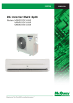
CMWV - 2004 Vertical Water Source Heat Pump And Cooling Only Unit Models: MWV 015 A/AR MWV 020 A/AR MWV 025 A/AR MWV 030 A/AR MWV 040 A/AR MWV 050 A/AR Contents Features ......................................................................................................................... 2 Specification ............................................................................................................. 3- 4 Operating Limits ............................................................................................................ 5 Water Loop System Diagram........................................................................................ 6 Performance Tables ............................................................................................... 7 - 12 Dimensions Table ....................................................................................................... 13 Wiring Diagrams .................................................................................................. 14 - 16 Transportation and Storage ....................................................................................... 17 Installation ............................................................................................................ 17 - 22 Start-Up ....................................................................................................................... 23 Maintenance................................................................................................................. 24 Troubleshooting ................................................................................................... 24 - 25 Note: Installation and maintenance are to be performed only by qualified personnel who are familiar with local codes and regulations, and experienced with this type of equipment, Caution: Sharp edges and coil surfaces are a potential injury hazard. Avoid contact with them. Warning: Moving machinery and electrical power hazards. May cause severe personal injury or death. Disconnect and lock off power before servicing equipment. "McQuay" is a registered trademark of McQuay International. All rights reserved throughout the world. 2003 McQuay International "Bulletin illustrations cover the general appearance of McQuay International products at the time of publication and we reserve the right to make changes in design and construction at any time without notice." Page 1 Features High Energy efficiency The unit has high efficiency as the high energy/effect ratio and a Max. COP of 4.2 as well as saving the running cost due to water as cooling and heating media. Whisper- Quiet Operation Solid casing, special sound absorbing and thermal insulation material, separated fan and compressor as well as the special noise reduction for compressor ensure an effective noise control for the whole set. Easy and flexible installation The physical size of the unit is specially designed for space saving. It is therefore offering greatest flexibility in selecting installation location. Service and Maintenance Friendly The unique structure design: small and compact structure with many overhaul doors and high/low pressure overhaul valve which helps overhauling and maintenance. Also, Tube in tube heater exchanger specially designed for water loop heat pump set which reduces pipe block and ensures a longer use life and a higher thermal conductivity. Microcomputer Remote Control The microcomputer remote control has following functions: Five optional operation modes (heat/cool/dry/fan/auto) Fan speed can be set at high, medium, low and automatic. Sleep mode automatically increase set temperature since temperature is lower at night thus achieving healthy sleep. Microcomputer controlled thermostat precisely controls room temperature resulting in energy saving and increases comfort. Hot start and hot keep mode do not supply air for 30 sec. After deicing as well as initial operation of heating mode. This prevents cold draft and maintains the indoor comfort. Timer on/off can be preset for the maximum of 15 hours. A wide Operating Scope All products of AWV series have adopted air compressors with world famous brands. The operating scopes are: Water temperature: (a) Cooling 13-40 ℃ (b) Heating: 10-32 ℃ This series of types are applicable for residential, shopping complex, hotels and industries. Page 2 Specifications MODEL COOLING CAPACITY Btu/h HEATING CAPACITY POWER INPUT COOLING HEATING POWER SOURCE MWV015A MWV015AR 14330 Btu/h W - W - V/Ph/Hz 15360 4500 220 - 240 / 1 / 50 - 7500 220 - 240 / 1 / 50 4 3.9 - 3.5 - 3.85 m2 0.183 0.183 0.267 W 103 215 191 Depth mm 178 178 254 Width mm 178 178 203 CFM 440 600 740 347 WATER FLOW WATER PRESSURE DROP WATER CONNECTIONS L/s 208 283 GPM 3.48 4.44 5.7 L/s 0.222 0.305 0.361 mH2O 1.3 1.5 1.7 FPT I.D. mm OPERATING kg 3/4 19.05 SHIPPING kg Rated in accordance with ANSI/ARI Standard 320-1998 MODEL 93 95 115 - - 150 MWV030A COOLING CAPACITY Btu/h HEATING CAPACITY Btu/h COOLING HEATING POWER SOURCE W V/Ph/Hz - POWER INPUT MWV040AR MWV050A 37540 34130 - 10000 42660 3.7 3.7 - MWV050AR 47780 - 11000 220 - 240 / 1 / 50 - ROW / FIN PER INCH MWV040A 9000 EER FACE AREA MWV030AR 30720 W COP 52900 14000 12500 380 - 415 / 3 / 50 - 15500 380 - 415 / 3 / 50 - - - - 3 / 13 3 / 14 3 / 14 m2 0.267 0.315 0.315 W 261 275 473 Depth mm 254 254 254 Width mm 203 254 254 CFM 940 1176 1470 694 AIR FLOW WATER FLOW WATER PRESSURE DROP WATER CONNECTIONS WEIGHT 6000 220 - 240 / 1 / 50 3 / 12 AIR FLOW CONNECTIONS - 3 / 14 POWER INPUT FAN 25600 7000 3 / 14 FACE AREA POWER INPUT - 3.5 - ROW / FIN PER INCH WEIGHT 20478 MWV025A MWV025AR 23890 5600 4.2 COP CONNECTIONS - 4200 EER FAN MWV020A MWV020AR 19110 L/s 444 555 GPM 6.97 - - L/s 0.222 0.305 0.361 mH2O 2 2.5 3.5 FPT 3/4 I.D. mm OPERATING kg 125 19.05 - - SHIPPING Kg 160 - - Rated in accordance with ANSI/ARI Standard 320-1998 Notes: 1. a) EER = Energy Efficiency Ratio b) COP = Coefficient of Performance c) L/s = Liters per second 2. Nominal cooling and heating capacity are based on the conditions below: a) Cooling Capacity is based on 26.7°C (80°F) (DB), 19.4°C (67°F) (WB) entering air temp and 29.6°C (85°F)entering, 35°C (95°F) leaving water temp。 b) Heating Capacity is based on 21.1°C (70°F) (DB) entering air temp and 21.1°C (70°F) entering water temp。 3. All specifications are subjected to change by manufacture without prior notice. Page 3 Airflow Correction Factors Total Cooling Capillary Sensible Cooling Capillary kW -Cooling Total Heat Of Rejection Total Heating Capillary kW -Heating Total Heat Of Absorption 85 0.972 0.926 0.977 0.975 0.967 1.009 0.967 90 0.982 0.948 0.984 0.983 0.978 1.006 0.976 Percent of Nominal Airflow 95 100 105 0.994 1.000 1.007 0.974 1.000 1.027 0.993 1.000 1.011 0.991 1.000 1.008 0.990 1.000 1.009 1.003 1.000 0.997 0.989 1.000 1.010 110 1.010 1.055 1.018 1.015 1.017 0.995 1.019 115 1.013 1.066 1.028 1.018 1.024 0.993 1.025 150 269 208 420 302 170 - Fan Performance Table 50 cycle, 220volts, single phase (includes allowance for dry coil, and no filter) FAN EXTERNAL STATIC PRESSURE (Pa) MODEL SPEED 30 50 80 100 120 HI 208 MWV015A/AR LOW 139 HI 283 MWV020A/AR LOW 197 HI 404 400 385 375 350 MWV025A/AR LOW 324 317 294 284 275 HI 484 483 461 457 453 MWV030A/AR LOW 354 358 352 345 338 MWV040A/AR MWV050A/AR HI 703 667 619 576 542 453 - LOW 542 531 498 472 435 353 - HI 694 LOW 500 Electrical Data The electrical data is based at 220V~/50Hz and 380V/3N/50Hz Power Compressor MODEL Voltage Hz Phase RLA LRA MWV015A/AR 220/240 50 1 6.1 26 MWV020A/AR 220/240 50 1 8.6 34 MWV025A/AR 220/240 50 1 10.2 47 MWV030A/AR 220/240 50 1 13 54 MWV040A/AR 380/415 50 3 4.8 42 MWV050A/AR 380/415 50 3 7 42 Fan Motor FLA 0.5 1 0.85 1.15 1.3 3.6 Page 4 Total Unit FLA Voltage Range 5.2 9.8 13.1 5.8 - 187~264 187~264 187~264 187~264 342~456 342~456 Max. Circuit Ampacity 6 12.1 18.8 7.8 - Max. Fuse Size 15 20 25 15 - Operating Limits Air limits °C (Sl units) Cooling Heating Min. Ambient Air 19.4 21 Normal Ambient Air 26.7 21 35 26.7 19.4 21 26.7/19.4 21 35/21.7 26.7 Cooling Heating 13 10 29.4 21 40 32 Max. Ambient Air Min. Entering Air (1)&(2) Normal Entering Air, DB/WB Max. Entering Air, DB/WB (1)&(2) Note: 1. At ARI flow rate 2. Max and min values may not be combined. If one value is at max or min, the other two conditions may not exceed the normal condition. Water enthalpy °C (Sl units) Min. Entering Water (1)&(2) Normal Entering Water Max. Entering Water (1)&(2) Environment This equipment is designed for indoor installation only. Sheltered locations such as attics, garages, etc., generally will not provide sufficient protection against extremes in temperature and/or humidity, and equipment performance, reliability, and service life may be adversely affected. Power supply A voltage variation of ±10% of nameplate utilization voltage is acceptable. Three-phase system unbalance shall not exceed 2%. Operating voltages 220-240V~/50Hz ---------------------------------------------------------------------------- 198V min., 264V max. 380-415V/3N/50Hz ---------------------------------------------------------------------------- 342V min., 456V max. Additional information (initial start-up only) Standard conditions are guaranteed to start and operate in an ambient temperature of 5°C, with entering air at 5°C, with entering water at 21°C, with both air and water at the flow rates used in the ARI Standard 32086 rating test, for initial start-up in winter. Note: This is not a normal or continuous operating condition. It is assumed that such a start-up is for the purpose of bringing the building space up to occupancy temperature. Page 5 Water Loop System Diagram expansion tank water supply cooling tower air vent valve thermometer water pump boiler flow switch filter filter thermometer flow switch AWV unit ACC indoor unit drain valve AWV unit Page 6 AWSC outdoor unit Performance Tables Model: MWV 015A/AR 3 Air Flow: 760m /h Electrical Characteristics: 220V / 1Ph / 50Hz Water Flow (m3/h) E.W.T (oC) O.W.T ( C) 0.82 10 - 0.82 13 18 0.82 16 21 0.82 21 26 0.82 27 32 0.82 30 35 0.82 32 37 0.82 38 43 0.82 40 45 COOLING E.W.T = Entering Water Temperature O.W.T = Leaving Water Temperature o o HEATING o E.A.T ( C) Capacity (W) E.A.T ( C) Capacity (W) 19.4/13.9 26.7/19.4 35/21.7 19.4/13.9 26.7/19.4 35/21.7 19.4/13.9 26.7/19.4 35/21.7 19.4/13.9 26.7/19.4 35/21.7 19.4/13.9 26.7/19.4 35/21.7 19.4/13.9 26.7/19.4 35/21.7 19.4/13.9 26.7/19.4 35/21.7 19.4/13.9 26.7/19.4 35/21.7 5002 5204 5308 4856 5028 5129 4715 4858 4955 4578 4694 4788 4444 4535 4626 4311 4376 4464 4182 4223 4308 4056 4075 4157 16 21 27 16 21 27 16 21 27 16 21 27 16 21 27 16 21 27 16 21 27 - 3995 4014 4094 4119 4160 4243 4246 4311 4397 4378 4467 4556 4509 4623 4716 4644 4785 4881 4784 4953 5052 - E.A.T = Entering Air Temperature Page 7 Model: MWV 020A/AR 3 Air Flow: 1020m /h Electrical Characteristics: 220V / 1Ph / 50Hz Water Flow (m3/h) E.W.T (oC) O.W.T (oC) 1.1 10 - 1.1 13 18 1.1 16 21 1.1 21 26 1.1 27 32 1.1 30 35 1.1 32 37 1.1 38 43 1.1 40 45 COOLING E.W.T = Entering Water Temperature O.W.T = Leaving Water Temperature HEATING E.A.T (oC) Capacity (W) E.A.T (oC) Capacity (W) 19.4/13.9 26.7/19.4 35/21.7 19.4/13.9 26.7/19.4 35/21.7 19.4/13.9 26.7/19.4 35/21.7 19.4/13.9 26.7/19.4 35/21.7 19.4/13.9 26.7/19.4 35/21.7 19.4/13.9 26.7/19.4 35/21.7 19.4/13.9 26.7/19.4 35/21.7 19.4/13.9 26.7/19.4 35/21.7 6177 6426 6555 5997 6209 6333 5822 5999 6119 5653 5796 5912 5488 5600 5712 5323 5404 5512 5164 5215 5319 5009 5032 5133 16 21 27 16 21 27 16 21 27 16 21 27 16 21 27 16 21 27 16 21 27 - 5367 5392 5500 5532 5587 5699 5704 5790 5906 5880 6000 6120 6056 6210 6334 6238 6427 6556 6425 6652 6785 - E.A.T = Entering Air Temperature Page 8 Model: MWV 025A/AR 3 Air Flow: 1200m /h Electrical Characteristics: 220V / 1Ph / 50Hz Water Flow (m3/h) E.W.T (oC) O.W.T (oC) 1.32 10 - 1.32 13 18 1.32 16 21 1.32 21 26 1.32 27 32 1.32 30 35 1.32 32 37 1.32 38 43 1.32 40 45 COOLING E.W.T = Entering Water Temperature O.W.T = Leaving Water Temperature HEATING E.A.T (oC) Capacity (W) E.A.T (oC) Capacity (W) 19.4/13.9 26.7/19.4 35/21.7 19.4/13.9 26.7/19.4 35/21.7 19.4/13.9 26.7/19.4 35/21.7 19.4/13.9 26.7/19.4 35/21.7 19.4/13.9 26.7/19.4 35/21.7 19.4/13.9 26.7/19.4 35/21.7 19.4/13.9 26.7/19.4 35/21.7 19.4/13.9 26.7/19.4 35/21.7 7721 8033 8193 7496 7761 7916 7278 7499 7649 7066 7245 7390 6860 7000 7140 6654 6755 6890 6455 6519 6649 6261 6290 6416 16 21 27 16 21 27 16 21 27 16 21 27 16 21 27 16 21 27 16 21 27 - 6708 6740 6875 6916 6984 7124 7130 7238 7382 7350 7500 7650 7571 7763 7918 7798 8034 8195 8032 8315 8482 - E.A.T = Entering Air Temperature Page 9 Model: MWV 030A/AR 3 Air Flow: 1650m /h Electrical Characteristics: 220V / 1Ph / 50Hz Water Flow (m3/h) E.W.T (oC) O.W.T (oC) 1.59 10 - 1.59 13 18 1.59 16 21 1.59 21 26 1.59 27 32 1.59 30 35 1.59 32 37 1.59 38 43 1.59 40 45 COOLING E.W.T = Entering Water Temperature O.W.T = Leaving Water Temperature HEATING E.A.T (oC) Capacity (W) E.A.T (oC) Capacity (W) 19.4/13.9 26.7/19.4 35/21.7 19.4/13.9 26.7/19.4 35/21.7 19.4/13.9 26.7/19.4 35/21.7 19.4/13.9 26.7/19.4 35/21.7 19.4/13.9 26.7/19.4 35/21.7 19.4/13.9 26.7/19.4 35/21.7 19.4/13.9 26.7/19.4 35/21.7 19.4/13.9 26.7/19.4 35/21.7 9927 10328 10534 9638 9978 10178 9357 9641 9834 9085 9315 9501 8820 9000 9180 8555 8685 8859 8299 8381 8549 8050 8088 8249 16 21 27 16 21 27 16 21 27 16 21 27 16 21 27 16 21 27 16 21 27 - 8944 8986 9166 9221 9312 9498 9506 9650 9843 9800 10000 10200 10094 10350 10557 10397 10712 10926 10709 11087 11309 - E.A.T = Entering Air Temperature Page 10 Model: MWV 040A/AR 3 Air Flow: 1950m /h Electrical Characteristics: 380V / 3Ph / 50Hz Water Flow (m3/h) E.W.T (oC) O.W.T (oC) 1.92 10 - 1.92 13 18 1.92 16 21 1.92 21 26 1.92 27 32 1.92 30 35 1.92 32 37 1.92 38 43 1.92 40 45 COOLING E.W.T = Entering Water Temperature O.W.T = Leaving Water Temperature HEATING E.A.T (oC) Capacity (W) E.A.T (oC) Capacity (W) 19.4/13.9 26.7/19.4 35/21.7 19.4/13.9 26.7/19.4 35/21.7 19.4/13.9 26.7/19.4 35/21.7 19.4/13.9 26.7/19.4 35/21.7 19.4/13.9 26.7/19.4 35/21.7 19.4/13.9 26.7/19.4 35/21.7 19.4/13.9 26.7/19.4 35/21.7 19.4/13.9 26.7/19.4 35/21.7 12133 12623 12875 11780 12196 12440 11437 11783 12019 11103 11385 11613 10780 11000 11220 10457 10615 10827 10143 10243 10448 9839 9885 10083 16 21 27 16 21 27 16 21 27 16 21 27 16 21 27 16 21 27 16 21 27 - 11180 11233 11458 11526 11640 11873 11883 12063 12304 12250 12500 12750 12618 12938 13196 12996 13390 13658 13386 13859 14136 - E.A.T = Entering Air Temperature Page 11 Model: MWV 050A/AR 3 Air Flow: 2500m /h Electrical Characteristics: 380V / 3Ph / 50Hz Water Flow (m3/h) E.W.T (oC) O.W.T (oC) 2.3 10 - 2.3 13 18 2.3 16 21 2.3 21 26 2.3 27 32 2.3 30 35 2.3 32 37 2.3 38 43 2.3 40 45 COOLING E.W.T = Entering Water Temperature O.W.T = Leaving Water Temperature HEATING E.A.T (oC) Capacity (W) E.A.T (oC) Capacity (W) 19.4/13.9 26.7/19.4 35/21.7 19.4/13.9 26.7/19.4 35/21.7 19.4/13.9 26.7/19.4 35/21.7 19.4/13.9 26.7/19.4 35/21.7 19.4/13.9 26.7/19.4 35/21.7 19.4/13.9 26.7/19.4 35/21.7 19.4/13.9 26.7/19.4 35/21.7 19.4/13.9 26.7/19.4 35/21.7 14890 15492 15801 14457 14968 15267 14036 14462 14751 13627 13973 14252 13230 13500 13770 12833 13028 13288 12448 12572 12823 12075 12132 12374 16 21 27 16 21 27 16 21 27 16 21 27 16 21 27 16 21 27 16 21 27 - 13416 13479 13749 13831 13968 14248 14259 14475 14765 14700 15000 15300 15141 15525 15836 15595 16068 16390 16063 16631 16963 - E.A.T = Entering Air Temperature Page 12 Dimensions Data All dimensions are approximate. Certified drawings available upon request. DIMENSIONS UNIT SIZE A B C D E F inch mm inch mm inch mm inch mm inch mm inch 015 & 020 23.15 588 22.24 565 38.58 980 8.2 208 9.1 232 1.2 30 3/4 025 & 030 26.18 665 23.46 596 42.56 1081 11.3 287 10.5 267 1.2 30 3/4 40 30.12 765 24.25 616 48.82 1240 11.3 287 13.1 334 1.2 30 1 50 30.12 765 26.22 666 48.82 1240 11.3 287 13.1 334 1.2 30 1 Optional Return Air Duct Filter Standard 1” (21mm) UNIT SIZE 015 & 020 025 & 030 040 & 050 A inch 21.85 24.6 28.2 mm 555 625 725 B inch 17 20.75 20.75 mm 432 527 527 inch 1 1 1 C mm 555 625 725 B inch 17 20.75 20.75 mm 432 527 527 inch 2 2 2 mm 21 21 21 Optional 2” (51mm) UNIT SIZE 015 & 020 025 & 030 040 & 050 A inch 21.85 24.6 28.2 C mm 51 51 51 Page 13 mm WATER CONNECTIO NS (FPT) Wiring Diagrams Model: MWV 015 / 020A MODEL:AWV015A/020A RETURN AI R TEMP. SENSOR WATER TEMP. SENSOR COI L TEMP. SENSOR TRANSFORMER ( SLM) LI NE CONTROLLER C FM G/ Y YELLOW S BROWN R RED N BLUE L CM G/ Y BLUE RED WHI TE RED BLUE G/ R ORANGE BLUE C1 LP: LOW PRESSURE SWI TCH HP: HI GH PRESSURE SWI TCH FSW: FLOW SWI TCH C2 BLUE FM: FAN MOTOR CM: COMPRESSOR C1, C2: CAPACI TOR Model: MWV 015 / 020 AR MODEL:AWV015AR/020AR RETURN AI R TEMP. SENSOR WATER TEMP. SENSOR ( SLM) COI L TEMP. SENSOR WI RE CONTROLLER TRANSFORMER R C1 LP: LOW PRESSURE SWI TCH HP: HI GH PRESSUR SWI TCH FSW: FLOW WATER SWI TCH FM: FAN MOTOR CM: COMPRESSOR 4WV: 4 WAY VALVE BLUE C1, C2: CAPACI TOR Page 14 ORANGE BLUE FM Y/ G S BROWN CM YELLOW BLUE N RED C Y/ G RED Y/ G L WHI TE BLUE BLUE RED BLUE C2 Model: MWV 025 / 030 A MODEL:AWV025A/030A RETURN AI R TEMP. SENSOR WATER TEMP. SENSOR ( SLM) COI L TEMP. SENSOR WI RE CONTROLLER TRANSFORMER 红 C FM Y/ G KM1 S BROWN R YELLOW N BLUE L CM Y/ G RED Y/ G ORANGE RED T2 T3 L2 L3 RED RED BLUE WHI TE RED BLUE BLUE KM1 T1 L1 C1 LP: LOW PRESSURE SWI TCH HP: HI GH PRESSURE SWI TCH FSW: FLOW WATER SWI TCH C2 BLUE FM: FAN MOTOR CM: COMPRESSOR C1, C2: CAPACI TOR Model: MWV 025 / 030 AR MODEL:AWV025AR/030AR RETURN AI R TEMP. SENSOR WATER TEMP. SENSOR ( SLM) COI L TEMP. SENSOR WI RE CONTROLLER TRANSFORMER RED CM R FM: FAN MOTOR CM: COMPRESSOR 4WV: 4 WAY VALVE Page 15 BLUE C2 BLUE C1, C2: CAPACI TOR ORANGE RED C1 LP: LOW PRESSURE SWI TCH HP: HI GH PRESSUR SWI TCH FSW: FLOW WATER SWI TCH FM Y/ G KM1 S BROWN N BLUE L C Y/ G YELLOW Y/ G RED T1 T2 T3 RED RED BLUE L1 L2 L3 BLUE RED WHI TE BLUE KM1 Model: MWV 040 / 050 A MODEL:AWV040A/050A RETURN AI R TEMP. SENSOR WATER TEMP. SENSOR CM Y/ G COI L TEMP. SENSOR TRANSFORMER RED WI RE CONTROLLER ( SLM) BLACK BROWN YELLOW BLACK BLUE WHI TE BLUE RED FM Y/ G RED ORANGE RED C Y/ G R LP: S T LOW PRESSUR SWI TCH N BLACK FM: FAN MOTOR HP: HI GH PRESSUR SWI TCH CM: COMPRESSOR FSW: FLOW WATER SWI TCH C: CAPACI TOR DB3- A: PHASE PROTECTOR Model: MWV 040 / 050 AR Page 16 BLACKDB3- 71 A BLACK 81 OL BROWN Transportation and Storage Upon receipt of the equipment, check the carton for visible damage. Make a notation on the shipper's delivery ticket before signing. If there is any evidence of rough handing, the cartons should be opened at once to check for concealed damage, If any damage is found, notify the carrier within 48 hours to establish your claim and request their inspection and a report. The Warranty Claims Department should then be contacted. Don't stand or transport the machine on their sides, For storing, each carton is marked with "up-arrows. In the event that elevator transfer makes horizontal positioning unavoidable, absolutely insure that the machine is in the normal upright position for at least 24 hours before operating. Temporary storage at the joist must be indoors, completely shields from rain, snow, etc. High or Low temperature naturally associated with weather pattern will not harm the conditioners. Excessively high temperature of 160°F (60ºC) may deteriorate certain plastic materials and cause permanent damage. In addition, the solid-state circuit boards may experience operating problems. Installation General 1. 2. 3. 4. 5. 6. To prevent damage, this equipment should not be operated for supplementary heating and cooling during the construction period. Inspect the carton for any specific tagging numbers as requested by the installing contactor. At this time the voltage, phase and capacity should be checked against the plans. Check the unit sizes against the plans to be sure that the unit will be installed in the correct location. Before installation, check the available closet dimension versus the dimensions of the unit. Pay attention to the location and routing of water piping, and electrical wiring. The locations of these items are clearly marked on submittal drawings. The installing contractor will find it beneficial to confer with piping, sheet metal, ceiling and electrical foreman together before installing any conditioners. Unit location 1. 2. 3. 4. 5. 6. Locate the unit in an area that allows for easy removal of the filter and access panels, and has enough space for service personnel to perform maintenance of repair. Provide sufficient room to make water, electrical and duct connections. The contractor should make sure that access has provided including clearance for duct collars and fittings at water and electrical connections. Allow adequate room around the unit for a condensate trap. The unit can be installed in an equipment room. However, closet installations are more common for small vertical type units. Generally, the unit is located in the corner of a closet with the non-ducted, return air facing 90° to the door and the major access panels facing the door (Figure A). Alternatively, the unit can have a ducted return air with the opening facing the door and the major access panels facing 90° to the door (Figure B). It is recommended that the unit be located on top of a vibration absorbing material such as rubber or carpet to reduce any vibration. If optional field installed controls are required (boilerless systems), space must be provided for the enclosure to mount around the corner from the electrical entrances. Do not locate the side of the unit too close to a wall. Page 17 Typical closet installation with louver door return & with ducted return Duct and attenuation Discharge ductwork is normally used with these conditioners. Return air ductwork may also be required, but will require field installation of a 1" or 2" (21 or 51mm) return air duct collar/ filter rack kit. The discharge duct system will normally consist of a flexible connector at the unit, a non-insulation piece of the full duct size, a short run of duct, an elbow without vanes, and a trunk duct teeing into a branch circuit with discharge diffusers as shown in FIGURE C. The transition piece must not have an angle greater than 30 ° or severer loss of air performance can result. Do not connect the full duct size to the unit without using a transition down to the size of the discharge collar on the unit. With metal duct material, the sides only of the elbow and entirebranch duct should be internally lined with acoustic insulation for sound attenuation. Glass fiber duct board material is more absorbing and may permit omission of the flexible connector. The ductwork should be laid out so that there is no line of sight between the conditioner discharge and the distribution diffusers. Return air ducts can be brought in through a wall grille and then to the unit. The return duct system will normally consist of a flexible connector at the unit and a trunk duct to the return air grille. With metal duct material, the return air duct should be internally lined with acoustic insulation for sound attenuation. Glass fiber duct board material is more absorbing and may permit omission of the fiexible connector. Return air ductwork to the unit requires the optional 2" (51mm) return air duct collar/filter rack kit. The kit can be installed for face side or bottom filter removal. The flexible connector can then be attached to the 1" (25mm) duct collar. Don't use sheet metal screws directly into the unit cabinet for connection of supply or return air ductwork, especially return air ductwork which can puncture the drain pan or the air coil. Page 18 Ventilation Air Outside air may be required for ventilation. The temperature of the ventilation air must be controlled so that mixture of outside air and return air entering the conditioner does not exceed application limits. It is also general practice to close off the ventilation air system during unoccupied periods (night setback). The ventilation air system is generally a separate building subsystem with distribution ductwork. Simple introduction of the outside air into each return air plenum chamber reasonably close to the conditioner air inlet is not only adequate, but also recommended. Do not duct outside air directly to the conditioner inlet. Provide sufficient distance for thorough mixing of outside and return air. General 1. Be sure the available power is the same voltage and phase as that shown on the unit serial plate. Line and low voltage wiring must be done in accordance with local codes or the National Electrical Code, whichever is applicable. 2. Apply correct line voltage to the unit. Two 7/8" (22mm) holes are supplied on the side of the unit. A disconnect switch near the unit is repaired by code. Power to the unit must be sized correctly and have time delay (dual element) fuses or a HACR circuit breaker for branch circuit overcurrent protection. See the nameplate for correct ratings. 220-240 Volt operation and 50 cycle units All 220-240 volt single and three-phase units are factory wired for 220 and 380 volt operation. For 240-volt operation, the line voltage tap on the 18-volt transformer must be changed. Disconnect and cap the red lead wire and interchange it with the orange lead wire on the primary of the 18-volt transformer. Three-phase 50 cycle units require a neutral wire for 220-240/1/50 power. Fan speed change All units have three-speed fan motors (HI, MID, LOW) and are shipped for HI, MID & LOW speeds operation. On unit sizes 015 though 050, each fan motor is supplied with a 6-pin terminal block mounted on the fan motor. Page 19 Piping 1. All units are recommended to be connected to supply and return piping in a two-pipe reverse return configuration. A reverse return system is inherently self-balancing and requires only trim balancing where multiple quantities of units with different flow and pressure drop characteristics are connected to the same loop. A simple way to check for proper water balance is to take a differential temperature reading across the water connections. To insure proper water flow, the differential should be 10°F (5℃) to 14°F (8℃). A direct return system may also be made to word acceptably, but proper water flow balancing is more difficult to achieve and maintain. 2. The piping can be steel, copper or PVC. 3. Supply and return run outs are usually connected to the unit by short lengths of high pressure flexible hose which are sound attenuates for both unit operating noise and hydraulic pumping noise. One end of the hose should have a swivel fitting to facilitate removal for service. Hard piping can also be brought directly to the unit although it is not recommended since no vibration or noise attenuation can be accomplished. The hard piping must have unions to facilitate unit removal. See FIGURE D for typical piping setup. 4. 5. 6. 7. Supply and return shutoff valves are required at each conditioner. The return valve is used for balancing and should have a "memory stop" so that it can always be closed off but can only be reopened to the proper position for the flow required. No unit should be connected to the supply and return piping until the water system has been cleaned and flushed completely. After the cleaning and flushing has taken place, the initial connection should have all valves wide open in preparation for water system flushing. Condensate piping can be steel, copper or PVC. Each unit is supplied with a 3/4" (19.05mm) ODM copper stub. The condensate disposal piping must have a trap and the piping must be pitched away from the unit not less than 1/4" inch per foot (20mm per meter). Generally, the condensate trap is made of copper. See FIGURE E. A piece of vinyl hoses from the trap to the drain line is used for simple removal. A complete copper or PVC condensate system can also be used. Union fittings in the copper lines should be applied to facilitate removal. Page 20 1 1/ 2" ( 38mm) 1 1/ 2" ( 38mm) FI GURE E 1/ 4" PER FOOT ( 20mm PER METER) 8. No point in the drain system may be above the drain connection of any unit. 9. Automatic flow controlled devices must not be installed prior to system cleaning and flushing. 10. A high point of the piping system must be vented. 11. Check local code for the need for dielectric Flexible Hose Since hose may change in length from +2% to –4% under the surge of high pressure, it is necessary to provide sufficient slack for expansion contraction (see Figure F). WRONG RI GHT FI GURE F Cleaning and Flushing System 1. 2. Prior to first operation of any conditioner, the water circulating system must be cleaned and flushed of all construction dirt and debris. If the conditioners are equipped with water shut off valves, either electric or pressure operated, the supply and return run outs must be connected together at each conditioner location. This will prevent the introduction of dirt into the unit. Additionally, pressure operated valves only open when the compressor is operation. The system should be filled at the city water makeup connection with all air vents open. After filling, vents should be closed. The contractor should start main circulator with pressure reducing valve makeup open. Vents should be checked in sequence to bleed off any trapped air to assure circulation through all components of the system. Power to the heat rejecter unit should be off, and the supplementary heat control set at 80°F (27℃). While circulating water, the contractor should check and repair any leaks in the piping. Drain at the lowest point(s) in the system should be opened for initial flush and blow-down, making sure city water fill are set to make up water at the same rate. Check the pressure gauge at pump suction and manually adjust the makeup to hold the same positive steady pressure both before and after opening the drain valves. Flush should continue for at least two hours, or longer if required, to see clear, clean drain water. Page 21 3. 4. 5. 6. Supplemental heater and circulator pump should be shut off. All drains and vents should be opened to completely drain down the system. Short circuited supply and return runouts should now be connected to the conditioner supply and return connections. Teflon tape is recommended over pipe dope for pipe dope for pipe thread connections. Do not use sealers at the swivel flare connections of hoses. Trisodium phosphate was formerly recommended as a cleaning agent during flushing. However, many states and localities ban the introduction of phosphates into their sewage systems. The current recommendation is to simply flush linger with warm 80°F (27℃) water. Refill the system with clean water. Test the litmus paper for acidity, and treat as required to leave the water slightly alkaline (pH 7.5 to 8.5). The specified percentage of antifreeze may also be added at this time. Use commercial grade antifreeze designed for HVAC systems only. Do not use automotive grade antifreeze. Set the system control and alarm panel heat add setpoint to 70°F (21℃) and the heat rejection setpoint to 85°F (29℃). Supply power to all motors and start the circulating pumps. After full flow has been established through all components including the heat rejecter (regardless of season) and air vented and loop temperatures stabilized, each of the conditioners will be ready for check test and start-up and for air and water balancing. Page 22 Start-Up 1. 2. Open all valves to full open position and turn on power to the conditioners. Set thermostat for "Fan Only" operation by selecting "Off " at the system switch and "On" at the fan switch. If "Auto" fan operation were selected, the fan would cycle with the compressor. Check for proper air delivery. 3. All units have three-speed motors. 4. Set thermostat to "Cool". Many conditioners have time delays which protect the compressor against short cycling. After a few minutes of operation, check the discharge grilles for cool air delivery. Measure the temperature difference between entering and leaving water. It should be approximately 11/2 times greater than the heating mode temperature difference. For example, if the cooling temperature difference is 15°F (8℃), the heating temperature difference should have been 12°F (5℃). Without automatic flow control valves, a cooling temperature difference of 10°F to 14°F (5℃ to 8℃) is about right. Adjust the combination shutoff/balancing valve in the return line to a water flow rate which will result in the 10°F to 14°F (5℃ to 8℃) difference. 5. Set thermostat to "Heat ". Set system switch to the "Auto " position and depress the heat setting to the warmest selection. Some conditioners have built-in time delays which prevent the compressor from immediately starting. With most control schemes, the fan will start immediately. After a few minutes of compressor operation, check for warm air delivery at discharge grille. If this is a "cold building" start-up, leave unit running until return air to the unit is at least 65°F (18℃). Measure the temperature difference between entering and leaving air and entering and leaving water. With entering water of 60°F to 80°F (16℃ to 27℃), leaving water should be 6°F to 12°F(3.3℃ to 6.7℃) cooler, and the air temperature rise through the machine should not exceed 35°F(19℃). If the air temperature exceeds 35°F(19℃), the airflow rate is probably inadequate. If the water temperature difference is less than 6°F (3.3℃), the water flow rate is excessive. If the water temperature difference exceeds 12°F (6.7℃), then the water flow rate is inadequate. 6. Check the elevation and cleanliness of the condensate line. If the air is too dry for sufficient dehumidification, slowly pour enough water into the condensate pan to ensure proper drainage. 7. If the conditioner does not operate, the following points should be checked: a. Is proper voltage being supplied to the machine? b. Is the proper type of thermostat being used? c. Is the wiring to the thermostat correct? 8. If the conditioner operates but stops after a brief period, check for: a. Is there proper airflow?Check for dirty filter, incorrect ductwork. b. Is there proper water flow rate within temperature limits?Check water backflush unit if dirt clogged. 9. Check the unit for vibrating refrigerant piping, fan wheels, etc. 10. Do not lubricate the fan motor as it is prelubricated at the factory. Page 23 Maintenance 1. 2. 3. 4. 5. Normal maintenance on all conditioners is generally limited to filter changes. Lubrication of the fan motor is not required. Filter changes are required at regular intervals. The time period between changes will depend upon the project requirements. Some applications such as motels produce a lot of lint from carpeting and linen changes. It is suggested that the filter be checked at 60-day intervals for the first year until experience is acquired. If light cannot be seen through the filter when held up to sunlight or a bright light, it should be changed. A more critical standard may be desirable. The condensate drain pan should be checked annually and cleaned and flushed as required. Recording of performance measurements of volts, amps, and water temperature differences (both heating and cooling) is recommended. A comparison of logged data with start-up and other annual data is useful as an indicator of general equipment condition. Periodic lockouts always are caused by air or water problems. The lockout (shutdown) of the conditioner is a normal protective result. Check for dirt in the water system, water flow rates, water temperatures, airflow rates (may be dirty filter), and air temperatures. If the lockout occurs in the morning following a return from night setback, entering air below machine limits may be the cause. Troubleshooting Should a major problem develop, refer to the following information for possible cause and corrective steps: Neither fan nor compressor run 1. 2. 3. 4. The fuse may be blown or the circuit breaker is open. Check electrical circuits and motor windings for shorts or grounds. Investigate for possible overloading. Replace fuse or reset circuit breakers after fault is corrected. Wires may be loose or broken. Replace or tighten. Supply voltage may be too low. Check it with the power company. Control system may be faulty. Check thermostat for correct wiring and check 24-volt transformer for burnout. Fan operates but compressor does not 1. 2. 3. 4. 5. 6. 7. 8. Check capacitor. Wires may be loose or broken. Replace or tighten. The high pressure may have tripped due to: a) Fouled or plugged condenser ; b) Lack of or no condenser water ; c) Too warm condenser water ; d) Not enough airflow over the coil due to dirty filters; e) Coil or fan motor failure. The low temperature switch may have tripped due to: a) Fouled or plugged condenser ; b) Lack of or no condenser water ; c) Too warm condenser water ; d) Not enough airflow over the coil due to dirty filters ; e) Coil or fan motor failure ; Check thermostat setting, calibration and wiring. The compressor overload protection is open. If the compressor dome is extremely hot, the overload will not reset until cooled down. If the overload is external, replace it. If the overload is internal, replace the compressor. The internal winding of the compressor motor may be grounded to the compressor shell. If so, replace the compressor. The compressor winding may be open. Check continuity with ohmmeter. If the winding is open, replace the compressor. Page 24 Compressor attempts to start but doesn’t 1. 2. 3. Check capacitor. Check for defective compressor by making resistance check on winding. Check run capacitor. Compressor runs in short cycle 1. 2. 3. 4. 5. 6. Check thermostat mounting and location. Check all relays, relaying and contacts. Check run capacitor. Check high pressure switch. Check low temperature switch. See if reversing valve has not fully shifted to either side. Insufficient cooling or heating 1. 2. 3. 4. 5. Check thermostat for improper location. Airflow may be insufficient. Check and clean the filter. The reversing valve may be defective, creating a bypass of refrigerant. If the unit will heat, check the reversing valve coil. Check capillary tubes for possible restriction of refrigerant flow. Check for restriction in water flow. Insufficient water flow through condenser 1. 2. 3. Check to see that valves are open all the way. Check for air in lines. Check circulating pumps. Water drips from conditioner 1. 2. 3. 4. 5. 6. Check for plugged condensate drain. Check for dirty filter. Check to see if condensate drain runs uphill. See if blower motor is up to speed. Check for loose or mispositioned blower. Are drains properly trapped? Noisy unit operation 1. 2. 3. 4. 5. 6. 7. 8. Check for fan wheel hitting the housing. Adjust for clearance. Check for bent fan wheel. Replace if damaged. Check for loose fan wheel on shaft. Tighten. Make sure compressor is floating free on its isolator mounts. Check for tubing touching compressor other surface. Readjust tubing by bending slightly. Check screws on panels. Tighten. Check for chattering or humming in the contactor relays due to low voltage or a defective holding coil. Replace component. Check water balance to unit for proper water flow rate. Page 25 REGISTERED S&E ISO 9002 ©2003 McQuay International +1 (800) 432-1342 www.mcquay.com