1
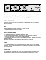
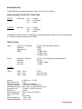
"MIC-AMP
MIC-AMP""
USER
MANUAL
manual page 1
Geachte klant,
Wij danken u hartelijk voor uw keuze en het vertrouwen dat u in ons produkt stelt.
U deed een goede keus, dit produkt is ontworpen door en voor professionele gebruikers.
Er is gebruik gemaakt van onze enorme "know how" in mengtafel en signaal processor technieken en dit
gekombineerd met hoogwaardige komponenten geeft u de zekerheid van een lange gebruiksduur.
Bovenstaande eigenschappen resulteren in een zeer betrouwbaar en bedrijfszeker
eindprodukt.
Deze gebruiksaanwijzing helpt u in het optimaal benutten van alle mogelijkheden die dit
produkt in zich heeft.
Mocht u nog vragen hebben dan kunt u zich altijd tot onze dealers wenden en in uiterste nood tot ons.
D&R ELECTRONICA WEESP B.V.
Rijnkade 15B
1382 GS WEESP-HOLLAND
The Netherlands
Phone: 0294-418 014
Fax: 0294-416 987
Website: http://www.d-r.nl
E-mail: [email protected]
manual page 2
PRECAUTIONS:
The product you have just unpacked is manufactured with safety in mind and is double checked in the test
department for reliability in its high-voltage section.
The MIC-AMP operates on 115 volt or 230 VAC, 50/60 Hz. In some products there is a voltage-selector built in
on the rear panel that indicates how the unit was set at the factory
If the voltage-selector does not indicate the voltage that your country is using, remove the linecord from the
mains and place the voltage-selector to its proper position. If no voltage selector is mounted inside your
Mic-amp, the factory has already set the mic-amp for the right voltage used in your country.
WARNING
Never change the position of the voltage-selector while the unit is still connected to the mains!
Should any solid object or liquid fall into the cabinet, turn off the unit immediately and have
it checked by qualified personnel before operating it any further.
When the unit is not to be used for a long period, turn the power off to conserve energy and to
extend the useful product life of your unit.
RACK MOUNTING
You can mount the MIC-AMP (height is 1HE, width is 9.1/2") in a 19" rack by using two MIC-AMP modules or
using one MlC-AMP and one blindpanel.
- Allow adequate air circulation to prevent internal heat build-up.
- Do not place the unit on surfaces (rugs, blankets, etc.) or near materials (curtains) that may
block ventilation.
-Do not install the unit near heat sources such as radiators or power-amplifiers or in a places subject to
excessive mechanical vibration.
FUSEHOLDER:
The fuseholder is mounted inside the unit (read product safety. When a fuse is blown, replacing it with a new
one may not be sufficient. The actual cause must be detected and solved.
Contact your nearest dealer if the unit can not be repaired by replacing the fuse. Use only the fuses
specified.
manual page 3
MIC-AMP
This two channel pre-amp is designed to be the answer for extremely high quality microphone amplification
especially on equipment which only are provide with line inputs.
It transforms the balanced microphone-level signal to an unbalanced -10 dBV line-level signal to correspond
to the line inputs on other equipment, for example P.C.M.-units and DAT/DCC recorders
SETTING UP PROCEDURE
Connect the microphone to the input of the MIC-AMP and the output of the MIC-AMP to the equipment it
should be connected to.
GAIN
When a signal at the input is present the normal led lits regularly. (is green)
Turn the gain clockwise until the clip led lits sporadic.
48 VOLT PHANTOME POWERING
For condenser microphones a 48 Volt phantome is provided per channel.
You will not hear any click while switching. This phantome circuit uses a softswitching arrangement.
This means the voltage is built up slowly. It is active after about 8 seconds.
The phantome power does not effect dynamic microphones when the microphone, cables and plugs are wired
symmerical. (balanced).
Be sure, that your microphone wiring is balanced to keep optimum signal to noise ratio.
PHASE
The phase switch reverses the wiring of the microphone input, so it changes the polarity of the connected
microphone. This can be useful when two microphones are out of phase or cancellations are to be heard in
the low frequency range.
CONNECTIONS
It is recommended to unplug the MIC-AMP from the mains outlet, before making the following connections.
Reconnect the mains-lead after the connections have been completed and make sure they are secure.
manual page 4
MICROPHONE INPUT
The MIC-AMP has two separate microphone inputs, each on an XLR connector.
WIRING DIAGRAM FOR IN/OUTPUT CONNECTORS
INPUTS
XLR female
pin 2
pin 3
pin 1
= in phase
= out of phase
= ground
OUTPUTS
XLR male
pin 2
pin 3
pin 1
= in phase
= out of phase
= ground
The MIC-AMP has two separate, low impedance, ground compensated outputs on a nominal operating level
of -10 dB and a maximum output level of +22 dBu.
SPECIFICATIONS
Inputs
stereo jack / XLR female
impedance
max input level
CMRR
6,25 mm / 3pin XLR female balanced
2 kOhm
+ 3 dBu
> 62 dB at 50 Hz
> 70 dB at 1 kHz
> 66 dB at 10 kHz
Output:
stereo jack / XLR male
impedance
nom. level
max. level
6,25 mm / 3 pin XLR male ground compensated
100 Ohm
- 7.8 dBu (-10 dBV)
+ 23 dBu
O dB / 100 Hz
O dB / 1 kHz
O dB / 10 kHz
0,012%
below noise level
below noise level
OVERALL
THD at:
Gain min.
Gain control range:
S/N-ratio (gain max.)
Frequency-response:
Phantome active after:
Normal led on at:
Clip led on at:
Power requirements:
Power consumption:
Fuse
Storage temperature
Operating temperature
+ 20 dB / max. + 60 dB
40 dB
- 129,0 dBr (A-weighted)
- 3 dB at 2 Hz, - 3 dB at 100 kHz
8 sec. Vph > 42 V (phantome led is red)
- 7,8 dBm (- 10 dBV) (nom. level)
+18 dBu
115volt - 230 volt AC 50/60 Hz
3VA
163 mA slow
- 10C to + 65C
+ 3C to + 40C
manual page 5
Dimensions
201 x 44 x 175 mm (w/h/d) (excl. controls)
201 x 44 x 198 mm (w/h/d) (incl. controls)
9,5" x 1HE (w/h)
Weight
Approx. 1,7 kg
CLEANING
Clean the cabinet, panel and controls with a dry soft cloth. Do not use a moistened cloth or any type of
solvent, such as alcohol or any other spirit, which might damage the finish.
CAUTION:
Never open your equipment yourself, there are no users serviceable parts inside, therefore we strongly advice
not to open the unit yourself.
- Opening a unit is only allowed to trained and qualified service engineers, who are fully aware of the fact that
it can be dangerous to service a mains powered unit.
- Always earth the unit.
- Only make use of the product in a way as is described in the manufacturers brochures and manuals, never
use it for other purposes than intended by the manufacturer.
- Never use this equipment in an environment with a high humidity and never expose it to water.
- Do not use this equipment in rain/snow or equivalent type of weather.
- Check your mains cord regularly and see if it is in a safe condition with a properly connected mainsplug on
one side and securely tightened in the equipment on the other side.
- Return your product yearly to your dealer for a safety checkup.
- The hazard of an electrical shock can be avoided by carefully following the rules mentioned above.
manual page 6
DECLARATION OF CONFORMITY
Manufacturers Name:
D&R Electronica Weesp b.v.
Manufacturers Address:
Rijnkade 15B,
1382 GS Weesp,
The Netherlands
declares that the product
Mic-amp
conforms to the following product specifications:
EMC:
EN 55022: 1987
CISPR 22 (1993) class B
EN 500082-1 (1992)
Supplementary Information:
The products herewith complies with the requirements of the EMC Directive 89/336/EEC (1989) as amended
by the CE Marking Directive 93/68/EEC (1993).
D&R Electronica Weesp b.v.
Rijnkade 15 B
1382 GS WEESP
The Netherlands
President of Engineering
manual page 7
PRODUCT SAFETY
This product is manufactured with the highest standards and is double checked in our quality control
department for reliability in the "HIGH VOLTAGE" section.
CAUTION
Never remove any panels, or open this equipment. No user servicable parts inside.
Equipment power supply must be grounded at all times.
Only use this product as described, in user manual or brochure.
Do not operate this equipment in high humidity or expose it to water or other liquids.
Check the AC power supply cable to assure secure contact.
Have your equipment checked yearly by a qualified dealer service center.
Hazardous electrical shock can be avoided by carefully following the above rules.
EXTRA CAUTION FOR LIVE SOUND
Ground all equipment using the ground pin in the AC power supply cable.
Never remove this pin. Ground loops should be eliminated only by use of isolation transformers for all inputs
and outputs. Replace any blown fuse with the same type and rating only after equipment has been
disconnected from AC power. If problem persists, return equipment to qualified service technician
PLEASE READ THE FOLLOWING INFORMATION
Especially in sound equipment on stage the following information is essential to know.
An electrical shock is caused by voltage and current, actually it is the current that causes the shock.
In practise the higher the voltage the higher the current will be and the higher the shock.
But there is another thing to consider and it is resistance.
When the resistance in Ohms is high between two poles, the current will be low and vica versa.
All three of these; voltage, current. and resistance are important in determining the effect of an electrical
shock.
However, the severity of a shock primarily determined by the amount of current flowing through a person.
A person can feel a shock because the muscles in a body respond to electrical current and because the heart
is a muscle it can affect, when the current is high enough.
Current can also be fatal when it causes the chest muscles to contract and stop breathing. At what potential is
current dangereous.
Well the first feeling of current is a tingle at 0.001 Amp of current.
The current between 0.1 Amp and 0.2 Amp is fatal.
Imagine that your home fuses of 20 Amp can handle 200 times more current than is necessary to kill. How
does resistance affect the shock a person feels.
A typical resistance between one hand to the other in "dry" condition could well over
100,000 Ohm.
If you are playing on stage your body is perspiring extensively and your body resistance is lowered by more
than 50%. This is a situation in which current can easily flow.
Current will flow when there is a difference in ground potential between equipment on stage and in the P.A.
system. Please do check if there is any potential between the housing of the mikes and the guitarsynth amps,
which will be linked by your body on stage. Imagine, a guitar in your hand and your lips close to the mike! A
ground potential difference of above 10 volts is not unusual, in improperly wired buildings it can possibly be as
high as 240 volts.
manual page 8
Allthough removing the ground wire sometimes cures a system hum, it will create a very hazardeous situation
for the performing musician.
Always earth all your equipment by the grounding pin in your mains plug.
Hum loops should be only cured by proper wiring and isolation input/output transformers.
Replace fuses always with the same type and rating after the equipment has been turned off and unplugged.
If the fuse blows again you have an equipment failure, do not use it again and return it to your dealer for repair.
And last but not least be carefull not to touch a person being shocked as you, yourself could also be shocked.
Once removed from the shock, have someone send for medical help inmediately
Always keep the above mentioned information in mind when using
electrically powered equipment.
manual page 9