1
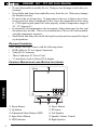
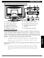
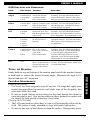
VMA1891
18.1” TFT LCD COLOR
M O N I T O R
OWNER’S MANUAL
INSTALLATION GUIDE
OWNER’S MANUAL
INTRODUCTION:
The Clarion VMA1891 is a full-featured 18.1" TFT LCD Color Monitor. It can be
used as:
• A stand-alone monitor with a home PC or Laptop Computer.
• A monitor integrated into a Clarion mobile multimedia system using auxiliary
built-in Video Composite (RCA) or S-Video inputs.
• A mobile PC monitor through the VGA input.
ABOUT THE MANUAL AND WARRANTY:
To start enjoying your new Clarion VMA1891, please read the instructions listed
in this manual. Keep all instructions for future reference. Please fill out and send
in the enclosed warranty card to protect your purchase and aid in warranty service.
Also, save your original sales receipt as proof of purchase.
NOTE: When using the VMA1891 with other Clarion multimedia products,
please refer to their separate owner’s manuals for operating procedures.
TABLE OF CONTENTS:
PRECAUTIONS:
• This set can be use in 12V, negative ground vehicles or home applications. Be
sure to consult your Clarion Dealer before installing it in 24V vehicles.
• Do not operate the set in ways other than described in this guide. Doing so may
damage it.
• SAFETY FIRST! For rear seat use only. Do not install anywhere that permits
viewing by the driver. Monitor must not be located in a motor vehicle at any
point forward of the back of the front seats. Monitor must never be used in any
manner that will distract or interfere with driver’s safe operation of the vehicle.
• Be careful not to run down the car battery while using the set with the car
stopped.
• For safety, install the set in a position at which the driver cannot see it.
Introduction
INTRODUCTION . . . . . . . . . . . . . . . . . . . . . . . . . . . . . . . . . . . . . . 1
PRECAUTIONS . . . . . . . . . . . . . . . . . . . . . . . . . . . . . . . . . . . . . . .1
. . . . . . . . . . . . . . . . . . . . . . . . . . . . . . . . . .2
PACKAGE CONTENTS
CONTROL DESCRIPTION AND BUTTON LOCATIONS . . . . . . . . . . . . . . . . . .2
REAR CONTROLS AND CONNECTOR LOCATIONS . . . . . . . . . . . . . . . . . . . .3
OPERATION DESCRIPTIONS . . . . . . . . . . . . . . . . . . . . . . . . . . . . . . . .3
OSD OPERATION DESCRIPTIONS . . . . . . . . . . . . . . . . . . . . . . . . . . . .4
CARE AND MAINTENANCE . . . . . . . . . . . . . . . . . . . . . . . . . . . . . . . .5
110VAC HOME APPLICATIONS . . . . . . . . . . . . . . . . . . . . . . . . . . . . .6
WIRING PRECAUTIONS (+12V OPERATION) . . . . . . . . . . . . . . . . . . . . .7
12VDC APPLICATIONS . . . . . . . . . . . . . . . . . . . . . . . . . . . . . . . . . .7
ABOUT INSTALLATION . . . . . . . . . . . . . . . . . . . . . . . . . . . . . . . . . . .8
SPECIFICATIONS & TROUBLESHOOTING . . . . . . . . . . . . . . . . . . . . . . . . .9
1
VMA1891 18.1” TFT LCD Color Monitor
• Do not disassemble or modify the set. Doing so may damage it and voids your
warranty.
• Keep drinks and drops from umbrellas away from the set. Water may damage
the internal circuitry.
• Do not let the set become hot. If temperature in the car is high or the set has
been exposed to direct sunlight and is hot, lower the temperature before using
it. (The liquid crystal panel will work properly within a temperature range of
30 – 113 degrees F.)
• In extremely cold temperatures, the movement of the picture may be slow and
the picture may be dark. This is not a malfunction. The set will work normally
once the temperature increases.
• Small black and shiny dots inside the liquid crystal panel are normal for liquid
crystal products.
PACKAGE CONTENTS:
The Clarion VMA1891 comes with the following items:
• RGB Cable for PC or Laptop Connection
• Video RCA Connector
• Three Conductor AC Power Cord
• 3.5 mm Stereo Jack to Stereo RCA adapter
AND
BUTTON LOCATIONS:
Controls
CONTROL DESCRIPTIONS
1 Down Button
2 Up Button
3 Adjustment Menu Button (OSD)
4 Input Select Button
5 LED Indicator
2
6 Power Button
7 IR Sensor
8 Left Speaker
9 Speaker Volume Control
0 Right Speaker
OWNER’S MANUAL
REAR CONTROLS
q
w
e
r
t
AND
CONNECTOR LOCATIONS:
VGA Input Connector
S-Video Input Connector
Composite Video Input
RS232 Port (Not Available)
y DC Input Connector +12Vdc
u Power Switch 110Vac 50-60 Hz.
i AC Input Connector 110Vac
50-60 Hz.
o L/R Audio Input Connectors
USB Input Connector
OPERATION DESCRIPTIONS:
When using this monitor in a 110Vac home environment. Plug the monitor into a
110Vac wall socket with the supplied AC power cable. Turn the rear AC Power
switch to the ON position. Press the front panel’s power button to power the
monitor. The monitor remembers the last input source selected and restarts using
that input. The initial factory default setting is the RGB input.
Choose the proper input source by pressing the Input Select Button on the front of
the monitor.
Operation
NOTE: The LED will be green under normal signal input. If no input signal is
detected the monitor will display a flashing error message for that
particular source. The LED will turn orange upon entering the power
saving mode after five seconds.
NOTE: In some cases, if the RGB, Video, or S-Video signal is low, the LED will
turn orange and enter a power saver mode after five seconds. This may
happen if you are viewing a TV station with a very weak signal. Press
the Power button on the front of the monitor to exit the power saver
mode.
3
VMA1891 18.1” TFT LCD Color Monitor
OSD OPERATION DESCRIPTIONS:
1. Press the OSD Menu button 3 to display the on-screen menu. Press the UP 2
or DN 1 button to scroll forward or backwards for each monitor settings.
2. Press the OSD Menu button 3 again to select the function. See list below for
individual function operations.
96
OSD Operation
OSD FUNCTIONS
OPERATIONS:
Sub Menus
Function
Brightness
None
Intensity of white light.
Contrast
None
Ratio of black to white
intensity.
Color
1) Red
2) Green
3) Blue
Intensity of Red color
Intensity of Green color
Intensity of Blue color
Position &
Quality
1) H-Position
2) V-Position
3) Frequency
4) Phase
Horizontal screen position
Vertical screen position
Vertical flicker
Horizontal flicker
Recall
4
AND
Icons
Operation
Use UP/DN buttons to increase or decrease
the level. Press the OSD display button twice
to exit the function.
Use UP/DN buttons to increase or decrease
the level. Press the OSD display button twice
to exit the function.
Use UP/DN buttons to select the adjustment
Sub Menu. Press the OSD button again. Use
the UP/DN buttons to increase or decrease the
level. Press the OSD display button to save
and exit to the Main Menu.
Use UP/DN buttons to select the adjustment
Sub Menu. Press the OSD button again. Use
the UP/DN buttons to increase or decrease
the level. Press the OSD display button to
save and exit to the Main Menu.
1)Factory setting Recalls the factory settings Use UP/DN buttons to select the adjustment
Yes/No
Sub Menu. Press the OSD button again. Use
2) 9300° K
Chromaticity coordinate
the UP/DN buttons to select choice. Press the
3) 6300° K
according to CIE 1931.
OSD button again to save. Select Exit, then
4) Exit
Exits Function
press the OSD button to exit the Main Menu.
OWNER’S MANUAL
OSD FUNCTIONS
AND
OPERATIONS:
Icons
Sub Menus
Function
Auto
Adjust
1) All
2) Auto Position
3) Auto Phase
4) Exit
Auto Sets all functions
Auto Screen Position
Auto Phase settings
Exits and Auto Saves
Input
Source
1) RGB
Input for PC
2) Video (RCA) Input for Composite Video
3) S-Video
Input for High quality
video (such as DVD)
Use UP/DN buttons to select the appropriate
Sub Menu. Press the OSD display button to
enter the input type. If no signal is present,
an error message will appear.
Display
Size
1) Normal
2) Expand
3) Full
Normal 4/3 Mode
Widescreen mode 16/9
Fills the height and width
of the screen
Use UP/DN buttons to select any adjustment
Sub Menu. Press the OSD display button to
save choice. Use UP/DN buttons to scroll to
Exit in Main Menu. Press OSD button to exit
Language
1) English
2) German
3) French
4) Italian
5) Spanish
1) OSD Timeout
2) OSD Position
3) OSD Color
Changes the OSD menu to Use the UP/DN buttons to select the
the user’s preferred
appropriate language. Press the OSD display
language.
button again to save the language and exit to
the Main Menu.
OSD
Control
4) Exit
Exit
None
15, 30, 45, 60 seconds
Hor. or Ver. Position
Blue, Green, Cyan, Magenta, None
Exits and Auto Saves
Operation
Use UP/DN buttons to select the appropriate
Sub Menu. Press the OSD display button to
activate the automatic function. Select Exit,
then press the OSD button to exit the function
Use UP/DN buttons to select the appropriate
Sub Menu. Press the OSD display button to
enter the Sub Menu. Use the UP/DN button
to scroll through the adjustment choices.
Press the OSD display button to save the
adjustment. Select Exit and press the OSD
display button to exit to the Main Menu.
Saves and Exits Main
Use UP/DN buttons to select the Exit
Menu. If OSD Timeout is function. Press the OSD display button again
activated, the menu will
to exit the Main Menu.
disappear after timeout.
OSD Functions
TILTING THE MONITOR:
Gently hold the top and bottom of the monitor panel and tilt the monitor forward
or backwards to achieve the desired viewing angle. Maximum tilt angle is 10°
forward and up to 45° backwards.
CARE AND MAINTENANCE:
Cleaning the cabinet:
• Use a soft, dry cloth and gently wipe off any dirt. For tough dirt, apply some
neutral detergent diluted in water to a soft cloth, wipe off the dirt gently, then
wipe again with a dry cloth.
• Do not use liquid cleaners on any surfaces as they may damage the cabinet or
cause the paint to peel. Also leaving rubber or plastic products in contact with
the cabinet for long periods of time may cause stains.
Cleaning the LCD Panel
• The LCD panel tends to collect dust, so wipe it off occasionally with a soft dry
cloth. The surface is easily scratched; so wipe with gentle light strokes.
• Do not use any type of hard objects to clean the surface. Damage may occur.
5
VMA1891 18.1” TFT LCD Color Monitor
110 VAC HOME APPLICATION:
Attaching a home VCR player.
110V Application
1. Connect the L/R audio outputs of the VCR player to the R-AUDIO-L inputs.
2. Connect the video output to the Video input on the VMA1891.
NOTE: Since there is only one set of L/R audio inputs on the VMA1891,
additional components must route their audio signals through the VCR
A/V inputs. This may limit the components attached to the VMA1891.
Attaching a home computer or laptop.
1. Connect the computer’s audio output (through the provided adapter cable) into
the R-AUDIO-L inputs on the VMA1891 (see diagram above for multiple
component attachment).
2. Connect the VGA output on the computer (using the provided VGA cable)
directly to the RGB input on the monitor.
Attaching a home DVD/CD Player.
1. Connect the DVD/CD player’s audio output into the R-AUDIO-L inputs on the
VMA1891 (see diagram above for multiple component attachment).
2. Connect the S-Video output on the DVD/CD (S-Video cable is not supplied)
directly to the S-Video input on the monitor.
6
OWNER’S MANUAL
NOTE: If there is no S-Video output on your DVD/CD player, connect its
video output to the video input on the VMA1891. The S-Video output
connection is preferred over the composite video output due to better
signal quality.
WIRING PRECAUTIONS (+12VDC OPERATION):
Read all wiring precautions. If you are not sure of the connections, contact your
authorized Clarion dealer.
• Be sure to disconnect the car’s negative (-) battery terminal to prevent short
circuits during installation.
• When creating passage holes through metal or plastic panels, use grommets to
eliminate any sharp edges created during drilling. This will protect power or
video wires from nicks or damaged causing a possible short circuit or failure.
• When connecting the ground lead, fasten the ground lead (black) securely to a
clean metal plate on the vehicle. Use sandpaper to remove any paint from the
surface where the ground terminal is attached.
• If the fuse should blow, check to see if the wiring is correct.
NOTE: This monitor’s audio section can only be power through the 110 Vac
connection. When using the monitor in a +12Vdc application,
additional audio components are required. See your Clarion Dealer
for additional equipment.
12VDC APPLICATIONS:
12V Application
7
VMA1891 18.1” TFT LCD Color Monitor
12V Application
12VDC APPLICATIONS: (CONT)
ABOUT INSTALLATION:
Installation of mobile audio and video components requires experience with a
variety of mechanical and electrical procedures. Even though this manual provides
general application drawings for your new Clarion VMA1891, it does not show the
exact installation methods necessary for your particular vehicle.
If you do not have the required knowledge and experience to successfully
complete the installation, we strongly recommend consulting an authorized
Clarion dealer about professional installation options.
8
OWNER’S MANUAL
SPECIFICATIONS:
Power Requirement:
DC Application: +12 volts dc (9-16 volts dc)
AC Application: 90-264 V, 50-60 Hz., 1.1-0.6 A
Power Consumption:
60 watts, Power On (8-12 W Standby)
5 amps (5000 mA)
Weight:
5.4 lb (12 kg)
Dimensions: Panel Only: 17-11/16 x 15-3/16 x 3-5/16 in. (449 x 385 x 84 mm)
With Stand 17-11/16 x 18-9/16 x 8-7/8 in. (449 x 470 x 225 mm)
View Angle:
Hor. +70°/-70° Ver. +70°/-40°
Tilt Angle of Hinge
10° Forward 40° Backwards
Audio Output
3W x 2 Max.
Display Type:
Color TFT Active Matrix LCD
Screen Size:
18.1" (Panel Dimensions 359.0 x 287.2 mm)
Pixel Pitch
0.2805 x 0.2805 mm
Pixels:
1280 x 1024
Screen Resolution:
1,310,720 Dots
Video Input Level (RCA): 1.0 volts peak to peak, NTSC
RGB Input Level:
0.75 volts peak to peak, TTL
TROUBLESHOOTING:
Symptom
System does not
work.
Cause
+12Vdc Fuse blown
or AC Power wires
are not connected.
Solution
Replace external fuse with the same
value. Check the wire connections and
connect it properly.
This may due to signals reflected off
buildings, mountains, etc. Check again in
a different place and direction or tune to a
strong TV station.
The screen displays
No signal or low
an error message then signal on the chothe LED turns orange sen input.
after 10 seconds.
Switch to another signal input. Check
connections and signal output from your
input source
The screen is dark.
The LED is orange,
not green
The monitor is in the
Sleep Mode.
Usage conditions are
poor.
Press the power button on the front of the
monitor. This will wake up the monitor.
This may happen if the temperature in the
vehicle is below 30°F or above 113°F.
Check again when the temperature is
between 30 and 113°F.
No picture on monitor.
The TV tuner is not
set to TV mode
Set the TV Tuner function to “TV” mode.
Specifications
The LED turns
The signal condition
orange when connect- is poor. The monitor
ed to the TTX001 or enters Sleep Mode.
a home VCR.
The Monitor is set to The screen will be blank if no picture
the wrong signal (signal) is inputted. Choose the proper
input mode.
input source selection.
9
FCC STATEMENT
This equipment has been tested and found to comply with the limits for a Class B digital device,
pursuant to Part 16 of the FCC Rules. These limits are designed to provide reasonable protection
against harmful interference in a residential installation. This equipment generates, uses, and can
radiate radio frequency energy and, if not installed and used in accordance with the instructions, may
cause harmful interference to radio communications. However, there is no guarantee that
interference will not occur in a particular installation.
If this equipment does cause harmful interference to radio or television reception, which can be
verified by turning the unit off and on, the user is encouraged to consult the dealer or an experienced
radio/television technician for help.
Clarion Corporation of America
661 West Redondo Beach Blvd
Gardena, CA 90247
800-Go-Clarion
www.clarion-usa.com
©2000 Clarion Corporation, Gardena, CA
2000-VMA1891-10 Rev. 2 (8/00)