1
AKENG44_Escalade Page 1 Wednesday, July 16, 2008 12:22 PM
Cadillac
Escalade
Owner’s Manual
Table of Contents
How to Use this Manual ................................ 3
Important Safety Precautions ....................... 5
Section 1
Instrumentation and Controls .................... 21
Section 2
Seats and Restraints ................................... 163
Section 3
Starting and Operating Instructions ........ 225
Section 4
Service and Maintenance .......................... 287
Section 5
Problems on the Road ............................... 353
Index .......................................................... 393
04AKENG44
AKENG44_Escalade Page 2 Wednesday, July 16, 2008 12:22 PM
Important Notes About this Manual
We thank you for choosing a
General Motors product, and we
want to assure you of our continuing commitment to your motoring
pleasure and satisfaction.
Production waste is recycled, with
some of the waste material recovered for re-use. Water requirements have been reduced to help
conserve natural resources.
This manual should be considered
a permanent part of the vehicle.
Keep it with the vehicle when sold,
to provide the next owner with
important operating, safety and
maintenance information.
All information, illustrations and
specifications in this manual are
based on the latest product information available at the time of
printing. We reserve the right to
make changes in the product without further notice.
Environment-friendly and recycled
materials were used in the development and manufacture of your
vehicle. The production methods
used to make your vehicle are also
environment-friendly.
...2
The illustrations throughout the
manual are typical and are not
intended to be exact representations of any part of your vehicle.
Please be aware that the vehicle
you purchased may not be
equipped with each option that is
explained in this manual.
This Owner’s Manual is supplemented by a “Maintenance Schedule and Warranty and Owner
Assistance Information” booklet.
Although we feel that this Owner’s
Manual is complete, in that it
covers the more important vehicle
operating information, it is most
valuable when used with the
Maintenance Schedule.
AKENG44_Escalade Page 3 Wednesday, July 16, 2008 12:22 PM
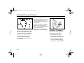
How to Use this Manual
When it comes to service, keep in
mind that your dealer knows your
vehicle best and is committed to
your complete satisfaction. Your
dealer invites you to return for all
of your service needs both during
and after the warranty period.
Should you have any concern that
has not been handled to your satisfaction, follow the steps outlined
in the “Maintenance Schedule and
Warranty and Owner Assistance
Information” booklet.
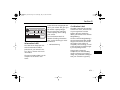
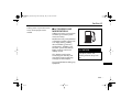
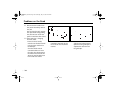
FOR CONTINUING SATISFACTION AND QUALITY, KEEP YOUR
GM VEHICLE ALL GM. GENERAL
MOTORS PARTS ARE IDENTIFIED
BY ONE OF THESE TRADEMARKS:
Use this manual to learn about the
features of your new vehicle and
how they operate.
The manual is intended to be used
as a reference guide to help you to
quickly identify and use the various
features of your vehicle. For this
reason, the manual is organized
according to feature location as
opposed to feature operation.
It also includes some very important safety and maintenance information and even deals with some
problems you may have while
driving.
This manual is divided into five
sections:
• Section 1: Instrumentation
and Controls
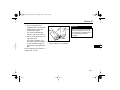
To get a general understanding of
how the content of this manual is
organized, imagine yourself sitting
in the driver’s seat. Your attention
is first focused on the instrument
panel directly in front of you, then
up and out to the mirrors,
windows and doors and continuing back around the vehicle to the
rear cargo area, then up to the
overhead area and the roof. The
content of this manual is organized to follow this order. The vast
majority of your vehicle’s instruments and controls are built into
these areas, and are discussed first
in this manual, in Section 1.
3...
AKENG44_Escalade Page 4 Wednesday, July 16, 2008 12:22 PM
How to Use this Manual
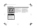
• Section 2: Seats and
Restraints
Next, focus on the center of
your vehicle: the seats and
safety belts. Information about
these features and about your
vehicle’s air bag system is covered in Section 2. Section 2
also includes any information
pertaining to child restraints.
...4
• Section 3: Starting and
Operating Instructions
Once you have been familiarized with your vehicle’s instruments, controls, seats and
restraint systems in Sections 1
and 2, Section 3 outlines your
vehicle’s starting and operating
instructions. This section
includes information about
your keys and keyless entry (if
equipped), about the ignition
and vehicle starting, and about
the transmission, transfer case
(if equipped), parking, traction,
steering, brake, and suspension
systems. It also covers your
vehicle’s specific loading and
towing capabilities.
• Section 4: Service and
Maintenance
The Service and Maintenance
section:
- contains fuel information
- helps you locate the various
components in your vehicle’s
engine compartment
- offers basic maintenance and
fluid information for the
major, easily-accessible
engine components (e.g., oil,
coolant, transmission fluid,
power steering fluid, brake
fluid, refrigerant, washer
fluid, battery)
AKENG44_Escalade Page 5 Wednesday, July 16, 2008 12:22 PM
How to Use this Manual
- contains information about
tire inflation, inspection, rotation and replacement
- locates and describes your
vehicle’s fuses and circuit
breakers
- contains some bulb replacement instructions and specifications
- includes major component
specifications and capacities
• Section 5: Problems on the
Road
This section tells you how to
handle certain problems you
may have while driving. It covers:
Each section begins with a brief
table of contents to help you
locate the information you want.
- jump starting your vehicle
- towing your vehicle
- engine overheating
- changing a flat tire
5...
AKENG44_Escalade Page 6 Wednesday, July 16, 2008 12:22 PM
Important Safety Precautions
CAUTION AND NOTICE BOXES
Safety Belts
CAUTIONS and NOTICES alert you
to conditions that may result in
injury, or that may damage your
vehicle.
CAUTION
Always wear your safety belt. Be
sure it is adjusted properly at all
times.
CAUTION
Means: This can hurt people.
NOTICE
Means: This can damage your
vehicle.
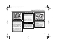
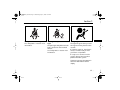
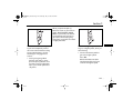
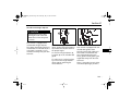
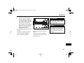
Seating Position
CAUTION
Do not adjust the driver's seat
when the vehicle is moving.
The seat could jerk and cause a
loss of control.
Sitting in a reclined position
when your vehicle is in motion
can be dangerous. Even if you
buckle up, your safety belts
can't do their job when the
seatback is excessively reclined.
...6
Do not let anyone ride where
they cannot wear a safety belt
properly. If you are in a crash
and you are not wearing a safety belt, you can be seriously
injured or killed. In the same
crash, you might not be injured
if you are buckled up. Always
fasten your safety belt, and
check that your passengers'
belts are fastened properly, too.
AKENG44_Escalade Page 7 Wednesday, July 16, 2008 12:22 PM
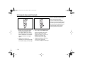
Important Safety Precautions
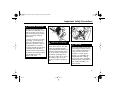
CAUTION (Continued)
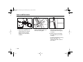
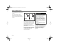
Wear your belt fitted closely
against the body. Do not wear
your shoulder belt under your
arm. Make sure the belt is not
twisted across your body.
CAUTION (Continued)
Wearing a safety belt improperly could cause serious injury.
The lap part of the belt should
be worn low and snug on the
hips, just touching the thighs.
In a crash, this applies force to
the strong pelvic bones, and
you would be less likely to slide
under the lap belt. If you slid
under it, the belt would apply
force to your abdomen. This
could cause serious or even fatal
injuries.
You could be seriously injured if
your belt is buckled in the
wrong place. Always buckle
your belt into the buckle nearest you.
CAUTION
The shoulder belt should go
over the shoulder and across
the chest. These parts of the
body are best able to take belt
restraining forces.
CAUTION (Continued)
A safety belt must be used by
only one person at a time. Do
not allow two children to share
the same belt.
Accident statistics show that
children are safer if they are
restrained in the rear seat.
7...
AKENG44_Escalade Page 8 Wednesday, July 16, 2008 12:22 PM
Important Safety Precautions
Air Bags
CAUTION
Both the safety belt restraint
system and the air bag restraint
system are designed to best
protect adults.
CAUTION (Continued)
A pregnant woman should
wear a lap-shoulder belt, and
the lap portion should be worn
as low as possible throughout
the pregnancy.
Anyone who is up against, or
very close to, an inflating air
bag could be seriously injured
or killed.
CAUTION (Continued)
Be sure that if children are too
small to be well restrained by
the safety belt system, that they
are secured in an appropriate
child restraint.
The presence of an airbag is not
a substitute for a safety belt and
is only effective in conjunction
with the safety belts.
...8
AKENG44_Escalade Page 9 Wednesday, July 16, 2008 12:22 PM
Important Safety Precautions
CAUTION (Continued)
Air bags are designed to be
used with the safety belts. Even
with an air bag, if you are in a
crash and not wearing a safety
belt, your injuries could be
much worse.
If you are too close to an inflating air bag, it could seriously
injure you. Safety belts help
keep you in position in case an
air bag inflates in a collision.
The driver should sit as far back
as possible while still able to
maintain control of the vehicle.
The path of an inflating air bag
must be kept clear of any
objects at all times.
CAUTION (Continued)
When an air bag inflates, it
leaves dust in the air. This dust
could cause breathing problems for people with a history of
asthma or other breathing trouble. To avoid this, everyone in
the vehicle should get out as
soon as it is safe to do so. If you
are unable to get out of the
vehicle, then open a window or
door.
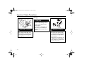
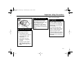
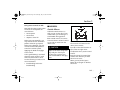
Children and Safety Restraints
CAUTION
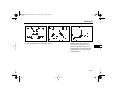
Never hold a baby in your arms
while riding in a vehicle. During
a crash a baby will become so
heavy you can’t hold it. For
example, in a crash at only
40 km/h, a 5.5 kg baby will
suddenly become a 110 kg
force on your arms. The baby
would be almost impossible to
hold. Secure the baby in an
infant restraint.
9...
AKENG44_Escalade Page 10 Wednesday, July 16, 2008 12:22 PM
Important Safety Precautions
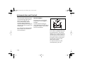
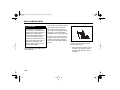
CAUTION (Continued)
A rear-facing child restraint in
the front seat could be pushed
into the seatback by the front
passenger's air bag if it inflates.
A child in a rear-facing child
restraint can be seriously
injured if this happens. In vehicles with the front passenger's
inflatable restraint system,
always secure a rear-facing
child restraint in the rear seat.
. . . 10
CAUTION
Infants who must use rearfacing child restraints cannot
ride safely in passenger air bagequipped vehicles that do not
have rear seats.
If, however, you secure a
forward-facing child restraint in
the front passenger seat, be
sure to move the front passenger seat as far back as it will go.
Leaving Your Vehicle
CAUTION
Avoid leaving your vehicle while
the engine is running.
Do not leave children in the
vehicle with the ignition key.
They could operate the power
windows or other controls and
could even make the vehicle
move. A child or others could
be injured or even killed.
AKENG44_Escalade Page 11 Wednesday, July 16, 2008 12:22 PM
Important Safety Precautions
CAUTION (Continued)
CAUTION (Continued)
It is very dangerous to leave
children inside the vehicle for
any extended period of time especially in hot weather. When
you leave the vehicle, take your
children with you.
• Be sure the shift lever is in
P (Park) and the parking
brake is firmly applied when
you leave your vehicle.
Vehicles with Automatic
Transmissions
CAUTION
If your vehicle is equipped with
an automatic transmission,
observe the following precautions to ensure proper and safe
operation. Otherwise, the vehicle may move suddenly and/or
cause an accident.
• Keep your foot firmly on the
brake pedal and do not race
the engine when shifting out
of P (Park) or N (Neutral).
• Do not shift into D (Drive) or
R (Reverse) when the engine
is racing.
• Do not shift into P (Park)
while the vehicle is moving.
Read Section 3, “Starting and
Operating Instructions”, for
more information.
11 . . .
AKENG44_Escalade Page 12 Wednesday, July 16, 2008 12:22 PM
Important Safety Precautions
CAUTION (Continued)
• Do not idle the engine in a
closed-in place, such as the
garage. Carbon monoxide
(CO) gas could get into your
vehicle.
Exhaust Warnings
CAUTION
• Things that can burn can
touch hot exhaust parts
under your vehicle and ignite.
Don’t park over papers,
leaves, dry grass or other
things that can burn.
• Engine exhaust can kill. It
contains carbon monoxide
(CO) gas, which you can’t see
or smell. It can cause unconsciousness and death.
. . . 12
• Idling the engine with the
windows closed and the air
conditioning fan off (if
equipped), may allow dangerous exhaust fumes into
your vehicle.
CAUTION (Continued)
• It can also be very dangerous
to drive with the trunk, rear
windows, hatch or rear doors
open. If you must drive with
one of these open or with
their seal broken, make sure
all other windows are closed
and turn the fan on to the
highest speed using any setting that brings in outside air.
Doing this will force outside
air into the vehicle.
• Make sure that no window,
door, trunk or hatch at the
rear of the vehicle is open if
you are pulling a trailer.
AKENG44_Escalade Page 13 Wednesday, July 16, 2008 12:22 PM
Important Safety Precautions
CAUTION (Continued)
If you suspect that exhaust is
entering your vehicle, drive
with all the windows open, turn
the air conditioning (if
equipped) on to any setting
that circulates outside air and
have the vehicle serviced immediately.
CAUTION (Continued)
• Engine exhaust may also be
entering your vehicle if:
– your exhaust system
sounds strange or different
– your vehicle gets rusty
underneath
– your vehicle has been
damaged or improperly
serviced
– the base of your vehicle,
especially your exhaust
pipe, is blocked by snow or
debris
Water and Your Vehicle
CAUTION
After a car wash or driving
through a puddle, the brakes
may not work well. Apply light
pedal pressure until the brakes
work normally.
Do not drive through deep
puddles. If water enters into an
air inlet, it might damage the
engine. If you must drive
through a puddle, drive carefully so as not to allow the water to
splash against the underbody of
the vehicle.
13 . . .
AKENG44_Escalade Page 14 Wednesday, July 16, 2008 12:22 PM
Important Safety Precautions
CAUTION (Continued)
Flowing or rushing water
creates strong forces. If you try
to drive through flowing water,
as you might at a low water
crossing, your vehicle can be
carried away. As little as six
inches of flowing water can
carry away a smaller vehicle. If
this happens, you and other
vehicle occupants could drown.
Don’t ignore police warning
signs, and otherwise be very
cautious about trying to drive
through flowing water.
. . . 14
Driving on Hills
CAUTION
If you need to stop on a hill, do
not hold the vehicle there with
the accelerator pedal. This
could damage the transmission.
Apply the brakes to hold the
vehicle in position.
When you are going down a
steep hill, use a lower shift
range, along with the brakes, to
control the vehicle’s speed.
Do not coast downhill in
Neutral or with the ignition off.
The brakes could overheat and
you could have an accident.
Vehicle Loading
CAUTION
Do not load your vehicle in
excess of the Gross Vehicle
Weight Rating or either Gross
Axle Weight Rating. If you do,
parts on your vehicle could
break and it could change the
way your vehicle handles. Overloading could result in loss of
vehicle control and personal
injury. It can also shorten the
service life of your vehicle.
AKENG44_Escalade Page 15 Wednesday, July 16, 2008 12:22 PM
Important Safety Precautions
Fuel and Other Flammable
Materials
CAUTION
Turn off the engine before
refueling.
CAUTION (Continued)
Things you put inside your vehicle can strike and injure people
in a sudden stop or turn, or in a
crash. Put things in the cargo
area of your vehicle and try to
spread the weight evenly.
Never stack things inside the
vehicle any higher than the
seatbacks. Do not leave unsecured child restraints inside the
vehicle. Try to secure anything
that is carried inside the vehicle.
When you open the fuel filler
cap, open it slightly at first to
release the pressure inside the
tank, then turn it all the way.
CAUTION (Continued)
Do not put paper or flammable
items in an ashtray. They may
catch fire from a cigarette.
To allow room for fuel expansion in the fuel tank (caused by
heat from the engine), fill the
tank only until the pump’s
automatic nozzle shuts off.
Never fill a portable fuel
container while it is in your
vehicle.
Dispense gasoline only into
approved containers.
Do not smoke while pumping
gasoline.
Do not carry combustible materials, such as gasoline, in the
vehicle.
15 . . .
AKENG44_Escalade Page 16 Wednesday, July 16, 2008 12:22 PM
Important Safety Precautions
Batteries
CAUTION
Vehicle batteries can hurt you.
They contain acid and electricity that can burn and gas that
can explode or ignite. Use care
and follow any applicable
instructions when working near
a battery.
Do not let battery fluid touch
your skin. If you do get it in your
eyes or on your skin, flush the
place with water and get medical help immediately.
Do not use a match or flame
near a vehicle’s battery. If you
need more light, use a flashlight.
. . . 16
CAUTION (Continued)
Every new GM vehicle uses an
AC Delco® battery that requires
no maintenance. However, if
another battery has filler caps,
be sure the right amount of
fluid is there. If it is low, add
water to make sure that there is
no explosive gas present.
Towing Your Vehicle
CAUTION
To help avoid injury to you or
others:
• Do not let anyone ride in a
vehicle that is being towed.
• Do not tow faster than safe or
posted speeds.
• Be sure to secure any loose or
damaged parts.
• Never get under a vehicle
after it has been lifted.
• Always use separate safety
chains on each side of the
vehicle.
AKENG44_Escalade Page 17 Wednesday, July 16, 2008 12:22 PM
Important Safety Precautions
CAUTION (Continued)
Exercise extreme caution
around the electric engine fan.
It sometimes starts by itself,
even when the engine is not
running.
Cooling System
Engine Compartment
CAUTION
Steam from an overheated
engine can burn you badly.
Stay away from the engine if
you see or hear steam coming
from it.
Be careful when working
around the engine compartment. Some engine parts can
get very hot and could burn
you.
CAUTION
CAUTION
Under some conditions the
ethylene glycol in engine coolant is combustible. To avoid
being burned, do not spill coolant on the exhaust system or on
hot engine parts. If you have
any doubt, have this operation
performed by a qualified
technician.
Do not run the engine if the
coolant is leaking. If the vehicle
loses all coolant, it could cause
an engine fire and you could be
burned.
Adding only plain water or a
liquid other than the recommended coolant can be
dangerous. The engine could
overheat, but you would not
get the overheat warning. The
engine could catch on fire and
you or others could be burned.
17 . . .
AKENG44_Escalade Page 18 Wednesday, July 16, 2008 12:22 PM
Important Safety Precautions
Changing a Flat Tire
CAUTION
Changing a tire can cause injury. The vehicle can slip off the
jack and injure you or other
people.
CAUTION (Continued)
Steam and scalding liquids from
a hot cooling system can blow
out and burn you badly. Never
turn the cap when the engine
and cooling system are hot.
. . . 18
Getting under a vehicle when it
is jacked up is dangerous. If the
vehicle slips off the jack, you
could be badly injured or killed.
Never get under a vehicle when
it is supported only by a jack.
CAUTION (Continued)
Rust or dirt on the wheel, or on
the parts to which it is fastened,
can make the wheel nuts
become loose after a time. The
wheel could come off and cause
an accident. When you change
a wheel, remove any rust or dirt
from the places where the
wheel attaches to the vehicle. In
an emergency, you could use a
cloth or a paper towel to do
this; but be sure to use a scraper
or wire brush later, if necessary,
to get all the rust or dirt off.
AKENG44_Escalade Page 19 Wednesday, July 16, 2008 12:22 PM
Important Safety Precautions
System Problems
NOTICE
CAUTION
Driving with the brake warning
light on can lead to an accident.
Have the brakes checked immediately if the brake warning
light stays on.
Do not keep driving with low oil
pressure. Your engine could
overheat and may catch on fire.
You or others could be burned.
Check the oil as soon as possible and have your vehicle
serviced.
CAUTION
If any warning light on the
instrument panel illuminates
while you are driving, immediately park your vehicle in a safe
place, and follow the instructions in this manual.
Additional electronic equipment, such as a CB radio, cellular phone, navigation package
or two-way radio, may interfere
with the operation of your vehicle’s engine, radio or other electronic systems and even
damage them. Please consult
with an authorized GM dealer
before installing electronic
equipment.
If the engine stalls while you are
driving, the power-assisted
brake and steering systems will
not work properly, and braking
and steering will require
substantial effort. Try to pull
over to a safe place before your
vehicle stops.
19 . . .
AKENG44_Escalade Page 20 Wednesday, July 16, 2008 12:22 PM
Important Safety Precautions
Additional Safety Cautions
CAUTION
Drinking and driving is very
dangerous. Your reflexes,
perceptions, attentiveness and
judgment can be affected by
even a small amount of alcohol.
You can have a serious, or even
fatal collision if you drive after
drinking. Please don’t drink and
drive or ride with a driver who
has been drinking. Ride home
in a cab or designate a driver
who will not drink.
. . . 20
CAUTION (Continued)
Medical research shows that
alcohol in a person’s system can
make crash injuries worse. This
is especially true of injuries to
the brain, spinal cord or heart.
This means that when any
person who has been drinking whether a driver or a passenger
- is in a crash, that person’s
chance of being killed or
permanently disabled is higher
than if the person had not been
drinking.
CAUTION
Unlocked doors can be dangerous. Make sure to lock all doors
while riding in the vehicle.
Turn the cruise control switch
off when you are not using it.
AKENG44_Escalade Page 21 Wednesday, July 16, 2008 12:22 PM
–
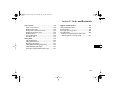
Section 1 - Instrumentation and Controls
1
Instr
um
en-
Dash-Mounted Instruments and Controls ......24
Instrument Cluster ..........................................26
Warning Lights ..............................................28
Driver Information Center ...............................39
Driver Information Center Buttons .................40
Trip/Fuel Information Menu...........................42
Vehicle Information Menu .............................45
Feature Customization ...................................49
Driver Information Center Messages ..............65
Analog Clock ...................................................78
Stabilitrak® System..........................................80
Stabilitrak Traction Control ............................82
Accessory Power Outlets .................................84
Lights ...............................................................86
Lights Main Switch ..........................................86
Automatic Headlight System..........................88
Instrument Light Dimmer ..............................89
Front Fog Lights.............................................89
Rear Fog Lights ..............................................90
Dome Lights ..................................................90
Illuminated Entry/Exit System ........................91
Reading Lights ...............................................91
Battery Saver .................................................91
Instrument Panel Switchbank .........................91
Heating and Air Conditioning System............ 92
Automatic Dual Zone Climate
Control System .............................................. 92
Automatic Rear Air Conditioning/Heating ..... 100
Operating Tips .............................................. 102
Air Outlets ..................................................... 103
Rear Window Defogger ................................. 103
Sound System and Clock............................... 104
Rear Seat Audio ............................................. 106
Audio Steering Wheel Controls ..................... 108
Anti-Theft Feature ......................................... 109
Antenna ........................................................ 110
Navigation System ........................................ 110
Controls Mounted on Steering
Wheel/Column ............................................. 111
Multifunction Lever ..................................... 111
Power Tilt Wheel Switch .............................. 112
Heated Steering Wheel ............................... 113
Cruise Control Buttons ................................ 113
Horn............................................................ 113
Audio Steering Wheel Controls .................... 113
Ignition Switch ............................................ 113
Gearshift Lever............................................. 114
Hazard Warning Flasher............................... 114
21 . . .
AKENG44_Escalade Page 22 Wednesday, July 16, 2008 12:22 PM
Section 1 - Instrumentation and Controls
Multifunction Lever .......................................115
Turn Signal ..................................................115
High-Low Beam Control ..............................116
Windshield Wipers .......................................116
Rear Wiper/Washer ......................................120
Cruise Control................................................121
Mirrors ...........................................................125
Outside Mirrors............................................125
Automatic Inside Day/Night Mirror..............128
Vanity Mirrors ..............................................128
Windows ........................................................129
Power Windows...........................................130
Doors .............................................................134
Manual Door Locks......................................134
Power Door Locks ........................................135
Rear Door Security Lock ...............................137
Power Running Boards ................................138
Rear Cargo Area ............................................138
Liftgate/Liftglass...........................................139
Power Liftgate..............................................141
Rear Area Storage ........................................145
Jack and Spare Tire Removal ........................145
. . . 22
Overhead Area and Roof............................... 145
Sun Visors.................................................... 145
Sunroof ...................................................... 146
Luggage Carrier........................................... 149
Storage .......................................................... 151
Center Console ............................................. 151
Rear Seat Armrest .......................................... 151
Glove Box ..................................................... 151
Cupholders ................................................... 152
Heated and Cooled Cupholders .................. 152
Rear Area Storage .......................................... 153
Luggage Carrier ............................................ 153
Ashtray and Lighter....................................... 153
Retained Accessory Power ............................ 154
Battery Rundown Protection ........................ 154
Ultrasonic Rear Parking Assist....................... 155
Problems with the Parking Assist System...... 158
Electric Power Management ......................... 159
Memory Feature ............................................ 160
AKENG44_Escalade Page 23 Wednesday, July 16, 2008 12:22 PM
Section 1
1 2
3
4
3
2
80
4
60
RPM x 1000
5
1
0
P R N D M
6
40
5
6 1 7
8
9
1
10
1
100 120
140
km/h
160
MPH
180
20
200
0
220
ABS
–
RES
SET
AUTO
AUX
11 12 13
14 15
16
17
18
19
23 . . .
AKENG44_Escalade Page 24 Wednesday, July 16, 2008 12:22 PM
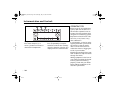
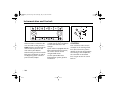
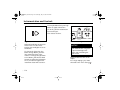
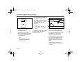
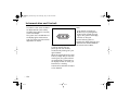
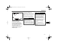
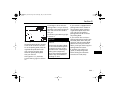
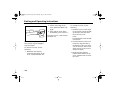
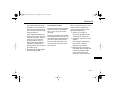
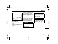
Instrumentation and Controls
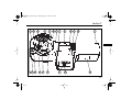
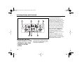
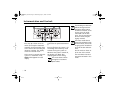
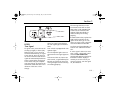
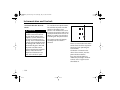
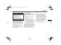
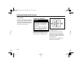
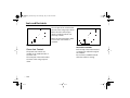
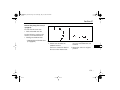
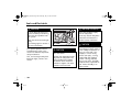
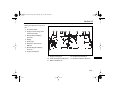
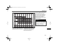
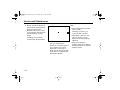
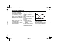
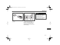
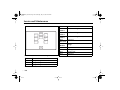
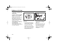
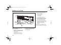
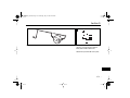
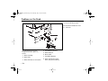
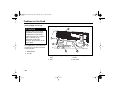
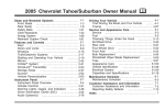
■ DASH-MOUNTED
INSTRUMENTS AND
CONTROLS
1. Air Vents
2. Multifunction Lever
3. Instrument Cluster
4. Hazard Warning Flasher
Control
8. Analog Clock
9. Navigation/Sound System
10. Stabilitrak® Button; Ultrasonic
Rear Parking Assist Disable
Switch
11. Power Tilt Wheel Switch
12. Main Light Controls
13. Dome Lights Override Button
5. Gear Shift Lever
14. Cruise Control Buttons
6. Tow/Haul Button
15. Horn
7. Driver Information Center
Buttons
16. Audio Steering Wheel
Controls
. . . 24
17. Automatic Dual Zone Climate
Control System
18. Instrument Panel Switchbank
This switchbank may contain
the following controls:
- Adjustable Accelerator and
Brake Pedals Control
- Heated Windshield Washer
Button
- Power Running Boards
Control (If equipped)
19. Glove Box
AKENG44_Escalade Page 25 Wednesday, July 16, 2008 12:22 PM
Section 1
7
2
3
1
6
2
5
–
3
2
80
4
60
RPM x 1000
5
1
0
P R N D M
6
40
100 120
140
km/h
160
MPH
180
20
200
0
220
ABS
4
8
25 . . .
AKENG44_Escalade Page 26 Wednesday, July 16, 2008 12:22 PM
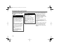
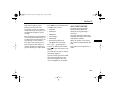
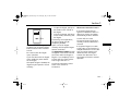
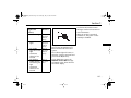
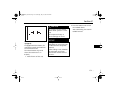
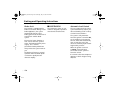
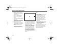
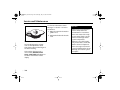
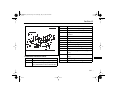
Instrumentation and Controls
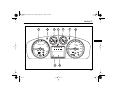
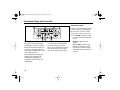
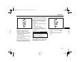
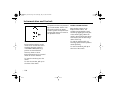
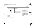
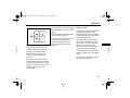
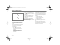
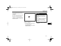
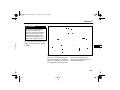
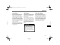
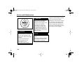
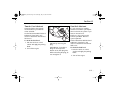
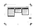
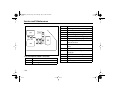
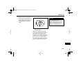
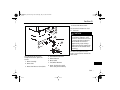
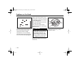
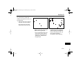
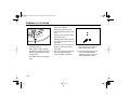
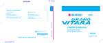
INSTRUMENT CLUSTER
The instrument cluster shown is
typical. Your actual cluster may
vary depending on the particular
options included in your vehicle.
The instrument cluster is designed
to let you know at a glance how
your vehicle is running.
For information about the various
warning lights located on your
instrument cluster or elsewhere in
your vehicle, see "Warning Lights"
later in this section.
Your vehicle also has a Driver
Information Center that works
along with the warning lights and
gages. See "Driver Information
Center" later in this section.
1. High Beam Indicator
The indicator light turns on
when the headlights are set to
high beams.
2. Turn Signal Indicators
An arrow will flash in the
direction of the turn or lane
change when the turn signal is
activated.
3. Engine Coolant Temperature
Gage
The engine coolant temperature gage shows the engine
coolant temperature. If the
pointer reaches the shaded
warning area of the gage, the
engine is too hot!
If the engine coolant has overheated, turn the engine off
immediately. See Sections 4
and 5 for more information on
your vehicle's cooling system.
. . . 26
AKENG44_Escalade Page 27 Wednesday, July 16, 2008 12:22 PM
Section 1
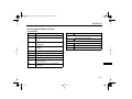
4. Odometer/Trip Odometer
5. Speedometer
The odometer shows how far
your vehicle has been driven.
The speedometer displays the
vehicle's speed.
The trip odometer can tell you
how far your vehicle has been
driven since you last set the
trip odometer to zero.
The reading will be indicated
in metric units of KM/H (kilometers per hour) or in
US-English units of MPH
(miles per hour).
To set the trip odometer to
zero, display the trip
odometer, then press the
Driver Information Center
set/reset button.
To display the odometer
reading while the ignition is
off, press the trip/fuel
information button.
See the following under
"Driver Information Center
Buttons" later in this section:
- Trip/Fuel Information Button
You can use the Driver
Information Center to change
your display's readings
between English and metric
units.
See "Vehicle Information
Menu" later in this section for
more information.
–
6. Fuel Gage
The fuel gage shows how
much fuel is in the fuel tank.
The fuel gage works only when
the ignition switch is on.
When the gage first indicates
empty there is still a little fuel
left, but you should refill the
tank as soon as possible.
The arrow on the gage
indicates the side of the vehicle
where the fuel door is located.
27 . . .
AKENG44_Escalade Page 28 Wednesday, July 16, 2008 12:22 PM
Instrumentation and Controls
7. Tachometer
The tachometer displays the
engine speed in thousands of
revolutions per minute (RPM).
8. Driver Information Center
Display
See "Driver Information
Center" later in this section for
information.
Warning Lights
Your vehicle has a number of
warning lights.
The warning lights go on when
there may be or there is a problem
with one of your vehicle's
functions. Some warning lights
come on briefly when you turn the
ignition key just to let you know
they're working properly.
Your vehicle also has a Driver
Information Center that works
along with the warning lights and
gages. See "Driver Information
Center" later in this section.
. . . 28
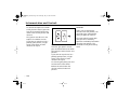
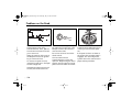
Engine Oil Pressure Warning
Light
This light should come on briefly
as you start the engine, as a check
to show you it is working properly.
If it doesn't come on, then have it
fixed so it will be ready to warn
you if there is a problem.
AKENG44_Escalade Page 29 Wednesday, July 16, 2008 12:22 PM
Section 1
If you have a problem with the oil,
this light may stay on after you
start the engine, or come on while
you are driving. This indicates
that oil is not going through the
engine quickly enough to keep it
lubricated. The engine could be
low on oil, or could have some
other oil problem. Have it fixed
right away.
CAUTION
Do not keep driving with low oil
pressure. Your engine could
overheat and may catch on fire.
You or others could be
burned. Check the oil as soon as
possible and have your vehicle
serviced.
NOTICE
Engine damage due to
neglected oil problems can be
costly to repair and is not
covered by your warranty.
See "Engine Oil" in Section 4 for
more information.
–
Charging System Light
This light should come on when
the ignition is on but the engine is
not running, as a check to show
you it is working properly.
If it doesn't come on, then have it
fixed so it will be ready to warn
you if there is a problem.
If it stays on or comes on while
you are driving, there may be a
problem with this system.
29 . . .
AKENG44_Escalade Page 30 Wednesday, July 16, 2008 12:22 PM
Instrumentation and Controls
Have it checked right away.
This light appears when the fluid
level in the reservoir is low or if
there is another problem with the
brakes.
Driving while this light is on could
drain your battery.
If there is a problem with the
battery charging system, a
message will be displayed. See
"Driver Information Center
Messages" later in this section.
If you must drive a short distance
with the light on, turn off all your
accessories, such as the radio and
air conditioner.
A chime will sound to alert you
when this warning light turns on.
See "Brake Master Cylinder Fluid"
in Section 4.
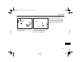
Brake System Warning Light
Your vehicle has "dual" brake
systems. If one system fails, the
other system can still stop your
vehicle.
This light should come on briefly
as you start your engine, as a check
to show you it is working properly.
If it doesn't come on, then have it
fixed so it will be ready to warn
you if there is a problem.
. . . 30
If the light comes on and the
chime sounds while you are
driving, pull over and stop
carefully.
The brake pedal may be harder to
push or it may go closer to the
floor. It may take longer to stop.
If the light stays on, have the
vehicle towed for service. The
brake system should be inspected
right away.
AKENG44_Escalade Page 31 Wednesday, July 16, 2008 12:22 PM
Section 1
This light also comes on when you
set your parking brake while the
ignition is on.
If you begin to drive while the
parking brake is not yet released,
the brake system warning light will
come on and a chime will sound to
alert you.
If it stays on after the parking brake
is fully released, it means you may
have a brake problem.
Have it checked right away.
If the light does not come on when
the parking brake is set, have your
vehicle serviced.
CAUTION
Driving with the brake warning
light on can lead to an accident.
Have the brakes checked
immediately if the brake
warning light stays on.
ABS
Have the vehicle towed for
service.
If the Brake System Warning Light
and the Antilock Brake System
Warning Light both turn on and
you hear a ten second chime,
there may be a problem with the
dynamic rear proportioning
system.
See "Dynamic Rear Proportioning"
under "Brakes" in Section 3 for
more information.
–
Antilock Brake System Warning
Light
This light should come on briefly
as you start your engine, as a check
to show you it is working properly.
If it doesn't come on, then have it
fixed so it will be ready to warn
you if there is a problem.
If it stays on or comes on while
you are driving, there may be a
problem with this system.
A text message may also appear in
the Driver Information Center
display.
31 . . .
AKENG44_Escalade Page 32 Wednesday, July 16, 2008 12:22 PM
Instrumentation and Controls
See "Driver Information Center
Messages" later in this section for
more information.
Stop as soon as possible and turn
the ignition off. Then start the
engine to reset the system.
If the light still stays on, or if it
comes on again while you're
driving, your vehicle needs service.
Until you get it fixed, the brakes
will still work, but without the
antilock feature.
CAUTION
Driving with any brake warning
light on can lead to an accident.
Have the brakes checked
immediately if any brake
warning light stays on.
. . . 32
If the regular brake system
warning light is also on, the
vehicle does not have antilock
brakes and there is a problem with
the regular brakes. Pull off the
road and stop carefully. Have the
vehicle towed for service.
See "Brake System Warning Light"
earlier in this section.
If the Brake System Warning Light
and the Antilock Brake System
Warning Light both turn on and
you hear a ten second chime,
there may be a problem with the
dynamic rear proportioning
system.
See "Dynamic Rear Proportioning"
under "Brakes" in Section 3 for
more information.
Malfunction Indicator Light
This light monitors the fuel,
ignition and emission control
systems.
This light should come on when
the ignition is on but the engine is
not running, as a check to show
you it is working properly.
If it doesn't come on, then have it
fixed so it will be ready to warn
you if there is a problem.
AKENG44_Escalade Page 33 Wednesday, July 16, 2008 12:22 PM
Section 1
If it stays on or comes on while
you are driving, there may be a
problem with this system.
Have it checked right away.
If the light stays on, you may be
able to correct the malfunction by
making sure the fuel cap is
properly installed, if you have just
refilled the tank with fuel.
NOTICE
If you keep driving your vehicle
with this light on, after a while,
your emission controls may not
work as well, your fuel economy
may not be as good and
your engine may not run as
smoothly. This could lead to
costly repairs that may not be
covered by your warranty.
NOTICE (Continued)
Modifications made to the
engine, transmission, exhaust,
intake or fuel system of your
vehicle or the replacement of
the original tires with other
than those of the same Tire
Performance Criteria can affect
your vehicle's emission controls
and may cause this light to
come on. Modifications to
these systems could lead to
costly repairs not covered by
your warranty.
In order for your vehicle to pass an
inspection of its emission control
equipment, the Malfunction
Indicator Light must be working
properly.
• If the engine is running, the
light must be off.
• If the ignition is on and the
engine is off, the light must be
on.
See "Accessories and Modifications" for more information.
33 . . .
–
AKENG44_Escalade Page 34 Wednesday, July 16, 2008 12:22 PM
Instrumentation and Controls
If you have recently replaced the
battery in your vehicle, or if the
battery has run down, the vehicle’s
on-board diagnostic system may
determine that the vehicle is not
ready for inspection. It may take
several days of routine driving in
order for the diagnostic system
to have enough data for the
inspection.
If the vehicle has been driven for
several days (with a fully charged
battery) prior to the inspection,
but the vehicle still does not pass
for lack of on-board diagnostic
system readiness, see your dealer
or a qualified service center to
prepare the vehicle for inspection.
. . . 34
After the initial bulb check, this
light comes on to indicate that the
system is off.
If the light stays on, or if it comes
on while you're driving when you
have not turned off Stabilitrak,
there may be a problem with this
system.
See your dealer for service.
Stabilitrak® Indicator Light
This light should come on briefly
as you start the engine, as a check
to show you it is working properly.
If it doesn't come on, then have it
fixed so it will be ready to warn
you if there is a problem.
When the Stabilitrak system
activates, the Stabilitrak Indicator
Light will flash.
When this warning light is on, the
traction control system will not
limit wheel spin.
Adjust your driving accordingly.
See "Stabilitrak System" later in this
section for more information.
AKENG44_Escalade Page 35 Wednesday, July 16, 2008 12:22 PM
Section 1
–
Safety Belt Reminder Light
See "Safety Belts" in Section 2 for
information.
Passenger Safety Belt Reminder
Light
The passenger safety belt reminder
light is located on the overhead
console.
See "Safety Belts" in Section 2 for
information.
Air Bag Light
This light will go on when you start
the engine and may flash for a few
seconds.
If it doesn't come on, then have it
fixed so it will be ready to warn
you if there is a problem.
If it stays on or comes on while
you are driving, there may be a
problem with this system.
A text message may also appear in
the Driver Information Center
display.
35 . . .
AKENG44_Escalade Page 36 Wednesday, July 16, 2008 12:22 PM
Instrumentation and Controls
See "Driver Information Center
Messages" later in this section for
more information.
Have the vehicle serviced right
away.
See Section 2 for more information
on the air bag light.
CAUTION
If the air bag light stays on or
comes on while you are driving,
there may be a problem with
this system. The air bags may
not inflate in a crash, or they
may inflate even when there
hasn’t been a crash. To avoid
injury to yourself or others,
have the vehicle serviced right
away.
Passenger Air Bag On/Off
Indicator
The indicator light is located in the
overhead console.
See "Passenger Sensing System" in
Section 2.
. . . 36
AKENG44_Escalade Page 37 Wednesday, July 16, 2008 12:22 PM
Section 1
–
Security System Light
Cruise Control Light
Tow/Haul Mode Light
This light should come on briefly
as you start the engine, as a check
to show you it is working properly.
This light turns on whenever you
set the cruise control.
This light should come on when
the tow/haul mode has been
selected. See "Tow/Haul Mode"
under "Trailer Towing" in
Section 3.
If it doesn't come on, then have it
fixed so it will be ready to warn
you if there is a problem.
See "Cruise Control" later in this
section for more information.
See "PASS-Key® III Plus Electronic
Immobilizer System" in Section 3
for information on the PASS-Key®
system.
Also, see "Theft Deterrent System"
in Section 3 for more information
on this light.
37 . . .
AKENG44_Escalade Page 38 Wednesday, July 16, 2008 12:22 PM
Instrumentation and Controls
Lights On Reminder Light
Fog Lamp Light
Rear Fog Lamp Light
This light turns on as a reminder
whenever the parking lights are
on.
This light will come on when the
fog lights are turned on. See "Fog
Lights" later in this section for
more information.
This light will come on when the
rear fog lights are turned on. See
"Rear Fog Lights" later in this
section for more information.
See "Lights" later in this section for
more information.
. . . 38
AKENG44_Escalade Page 39 Wednesday, July 16, 2008 12:22 PM
Section 1
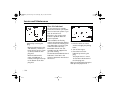
The Driver Information Center can
be used to program various
customization features that may
be available with your vehicle.
See "Feature Customization" later
in this section.
If your vehicle is equipped with
these features, the compass and
outside temperature will appear
on the display whenever the
ignition is on and the trip/fuel
information menu is active.
When the ignition is turned on,
the Driver Information Center will
turn on.
DRIVER INFORMATION
CENTER
The Driver Information Center
gives you the status of many of
your vehicle's systems.
The display is located at the
bottom of the instrument cluster.
The control buttons are located on
the instrument panel, to the right
of the steering wheel.
–
After a short delay, the Driver
Information Center will recall the
mode last displayed before the
engine was turned off.
If the system senses a problem, a
message will appear on the
display.
See "Driver Information Center
Messages" later in this section for
more information.
See "Driver Information Center
Buttons" later in this section for
more information.
39 . . .
AKENG44_Escalade Page 40 Wednesday, July 16, 2008 12:22 PM
Instrumentation and Controls
• Fuel Range
• Average Fuel Economy
• Fuel Used
• Timer
• Transmission Fluid Temperature
• Average Speed
A blank page ends this menu.
Driver Information Center
Buttons
The control buttons are located on
the instrument panel, to the right
of the steering wheel.
See the following, later in this
section, for more information:
(VEHICLE INFORMATION
BUTTON)
• Trip/Fuel Information Menu
Pressing this button repeatedly will
allow you to scroll through the
following displays:
(TRIP/FUEL INFORMATION
BUTTON)
• Engine Oil Life
Pressing this button repeatedly will
allow you to scroll through the
following displays:
• Battery Voltage
• Odometer
• Trip Odometer
. . . 40
• English/Metric Unit Selection
• Oil Pressure
• Remote Keyless Entry
Transmitter Matching
AKENG44_Escalade Page 41 Wednesday, July 16, 2008 12:22 PM
Section 1
• Compass Variance Zone
Settings (If equipped)
• Compass Calibration (If
equipped)
A blank page ends this menu.
See "Vehicle Information Menu"
later in this section for more
information.
–
(PERSONALIZATION
BUTTON)
Press the button repeatedly to
scroll through the list of
customizable features available on
your vehicle.
(SET/RESET BUTTON)
Press this button to reset Driver
Information Center features and to
turn off or acknowledge messages.
Use this button to do the
following:
Only available options will appear
in the display.
• to reset the trip odometer
To program personalization
settings, see "Feature Customization" later in this section.
• to reset the fuel used reading
• to start, stop or reset the timer
• to reset the average fuel
economy reading
41 . . .
AKENG44_Escalade Page 42 Wednesday, July 16, 2008 12:22 PM
Instrumentation and Controls
See the following, later in this
section, for more information:
Pressing this button repeatedly will
allow you to scroll through the
following displays:
- Trip/Fuel Information Menu
• ODOMETER
• to access the settings for the
displayed customization
feature
The odometer shows how far
your vehicle has been driven.
See "Feature Customization"
later in this section.
• to change the compass
variance zone
See the following, later in this
section, for more information:
- Vehicle Information Menu
• to clear messages from the
Driver Information Center
display
See "Driver Information Center
Messages" later in this section.
. . . 42
Trip/Fuel Information
Menu
Press this button to access the
trip/fuel information menu.
A blank page ends this menu.
The reading will be indicated in
metric units of KM (kilometers)
or in US-English units of
MI (miles).
See "Vehicle Information
Menu" later in this section for
more information.
AKENG44_Escalade Page 43 Wednesday, July 16, 2008 12:22 PM
Section 1
• TRIP
The trip odometer can tell you
how far your vehicle has been
driven since you last set the trip
odometer to zero.
The reading will be indicated in
metric units of KM (kilometers)
or in US-English units of
MI (miles).
To reset this reading to zero,
first select its display, then press
the
button.
• FUEL RANGE
• AVERAGE ECONOMY
This display shows how far the
computer thinks you can travel
with the fuel that's in the tank.
This display shows the average
fuel economy since the last
time you reset the system.
The fuel range is calculated
using the average fuel
economy of recent driving
conditions.
The reading will be indicated
in metric units of L/100 KM
(the amount of fuel consumed
in liters per 100 km) or in
US-English units of MPG (Miles
Per Gallon).
The reading will be indicated in
metric units of KM (kilometers)
or in US-English units of
MI (miles).
If the range display shows
LOW, you should get fuel right
away.
To reset this reading to zero,
first select its display, then press
and hold the
button.
This item cannot be reset.
43 . . .
–
AKENG44_Escalade Page 44 Wednesday, July 16, 2008 12:22 PM
Instrumentation and Controls
• FUEL USED
This display shows how much
fuel has been used since you
last reset the system.
The reading will be indicated
in metric units of liters or in
US-English units of gallons.
To reset this reading to zero,
first select its display, then press
and hold the
button.
• TIMER
The timer feature acts as a
stopwatch.
To start the timer, first select its
display, then press the
button.
If, during a trip, you are stopping and starting your vehicle,
the timer will automatically
start timing where it left off the
last time you turned the ignition off.
The fields are for the hours,
minutes, and seconds.
The timer will roll back to
00:00:00 after 99:59:59.
To stop the timer without resetting it, first select its display,
then press the
button
briefly.
To reset the timer to 00:00:00,
press and hold the
button.
. . . 44
• TRANS TEMP (transmission
temperature)
This display shows the
transmission fluid temperature.
The reading will be indicated
in metric units of °C or in
US-English units of °F.
AKENG44_Escalade Page 45 Wednesday, July 16, 2008 12:22 PM
Section 1
• AVERAGE SPEED
This display shows your
average speed since you last
reset the system.
If, for example, you see 95%,
that means that the way you
are driving your vehicle, 95%
of the current oil life remains.
The reading will be indicated in
metric units of KM/H (kilometers per hour) or in US-English
units of MPH (miles per hour).
How frequently you have to
change the oil depends on
your driving patterns, engine
rpm and engine temperature.
To reset this reading to zero,
first select its display, then press
and hold the
button.
It is the owner's responsibility
to check the engine oil level
regularly.
Vehicle Information Menu
Press this button to access the
vehicle information menu.
A blank page ends this menu.
Pressing this button repeatedly will
allow you to scroll through the
following displays:
• OIL LIFE REMAINING
This display shows the percentage of oil life remaining since
the system was last reset.
See "Engine Oil" in Section 4
for more information.
When the remaining oil life is
low, the CHANGE ENGINE OIL
SOON message will appear.
After the oil change message
comes on, change the engine
oil as soon as possible within
the next 1000 km (600 miles).
45 . . .
–
AKENG44_Escalade Page 46 Wednesday, July 16, 2008 12:22 PM
Instrumentation and Controls
Be sure to replace the engine
oil filter each time you change
engine oil.
Even if the oil life system does
not indicate that an oil change
is necessary, the engine oil and
filter must be changed at least
once a year.
After you change the oil, the oil
life monitor will need to be
reset. See your dealer for
service.
See "Engine Oil" in Section 4
for more information.
Also see the Maintenance
Schedule booklet for more
information.
• UNITS
• BATTERY VOLTAGE
You can scroll through and
activate one of the following
feature settings:
This display lets you monitor
battery voltage to make sure it
is charging properly.
- ENGLISH (English Units)
You may see the reading fluctuate. This is normal.
This setting lets you view
your displays in U.S. English
units.
- METRIC (Metric Units)
This setting lets you view
your displays in metric units.
When the desired feature
setting is displayed, press the
button to select it.
If the current voltage is outside
the normal operating range,
LOW or HIGH will appear on
the display next to the numeric
voltage reading.
If there is a problem with the
battery charging system, a
message will be displayed. See
"Driver Information Center
Messages" later in this section.
The Charging System Light
may also appear on the
instrument cluster.
See "Charging System Light"
under "Warning Lights" earlier
in this section for more information.
. . . 46
AKENG44_Escalade Page 47 Wednesday, July 16, 2008 12:22 PM
Section 1
• OIL PRESSURE
This display shows the engine
oil pressure.
The reading will be indicated
in metric units of kPa or in
US-English units of PSI.
• PRESS
TO RELEARN
REMOTE KEY
See your dealer to purchase a
new transmitter and to have
transmitters matched to your
vehicle.
PRESS
TO CHANGE
COMPASS ZONE
Note: This feature may not be
available on all vehicles.
Your vehicle’s compass should
be pre-set to your zone.
If your vehicle is taken outside
this zone, it may be necessary
to adjust the compass to
compensate for variance.
Compass variance is the
difference between the earth’s
magnetic north and the true
geographic north.
To adjust for compass variance:
- See your dealer to find out
what zone you are in.
- Place the transmission in
P (Park).
- Press
repeatedly to select
this display.
- Press
repeatedly to select
the correct compass zone.
- Press the trip/fuel button until
a compass direction appears
on the display.
- Calibrate the compass, if
necessary.
47 . . .
–
AKENG44_Escalade Page 48 Wednesday, July 16, 2008 12:22 PM
Instrumentation and Controls
• PRESS
TO CALIBRATE
COMPASS
Note: This feature may not be
available on all vehicles.
If an incorrect reading is
displayed, first check that the
compass is set to the correct
variance zone. If it is, the
compass may need calibration.
There may be a strong
magnetic field (from various
magnetic objects on the
vehicle) interfering with the
compass.
Remove these objects or ask
your dealer for assistance.
. . . 48
Do not use other features such
as the power windows, sunroof
or the climate controls during
the calibration procedure.
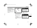
- Drive your car to an open
parking lot where you can
safely drive in a full circle.
- Press
repeatedly to select
the compass calibration
display.
- Press the
button.
CALIBRATING: DRIVE IN
CIRCLES will appear on the
display.
- Slowly and safely drive your
vehicle in a full circle until
CALIBRATION COMPLETE
appears on the display.
Vehicle speed must be less
than 8 km/h (5 mph).
If CAL appears on the display,
then the compass did not
calibrate. Repeat the
procedure to calibrate the
compass.
AKENG44_Escalade Page 49 Wednesday, July 16, 2008 12:22 PM
Section 1
Feature Customization
- DISPLAY IN ENGLISH
- PARK TILT MIRRORS
The Driver Information Center can
be used to program various
customization features that may
be available with your vehicle.
- DISPLAY LANGUAGE
- EASY EXIT RECALL
- AUTO DOOR LOCK
(automatic door lock)
- EASY EXIT SETUP
- AUTO DOOR UNLOCK
(automatic door unlock)
- DISPLAY DIGITAL SPEED
Only available options will appear
in the display.
Your vehicle may be equipped
with the following features that
can be individually personalized.
One preferred setting per available
customization feature can be
stored.
- REMOTE DOOR LOCK
- REMOTE DOOR UNLOCK
- MEMORY SEAT RECALL
- FACTORY SETTINGS
–
- EXIT FEATURE SETTINGS
- DELAY DOOR LOCK
- EXIT LIGHTING
- APPROACH LIGHTING
- CHIME VOLUME
49 . . .
AKENG44_Escalade Page 50 Wednesday, July 16, 2008 12:22 PM
Instrumentation and Controls
ENTERING PROGRAMMING
MODE
1. Turn the ignition on.
2. Place the transmission in
P (Park).
3. Turn off the headlights to
avoid draining the battery.
4. Press to scroll through the
list of programmable features
available on your vehicle.
To exit programming mode, see
"Exiting Programming Mode" later
in this section.
. . . 50
FEATURE CUSTOMIZATION
MENU
To enter this menu, see "Entering
Programming Mode" earlier in this
section.
Once you have entered programming mode, press the button
repeatedly to scroll through the list
of customizable features available
on your vehicle.
Only available options will appear
in the display.
The following features, which are
automatically recalled, can only be
programmed to one vehicle
setting:
• PRESS
TO DISPLAY IN
ENGLISH
Note:
This menu item will not
appear if the Driver
Information Center display is
already set to the English
language.
With this item displayed, press
the
button to select English
as the Driver Information
Center display language.
AKENG44_Escalade Page 51 Wednesday, July 16, 2008 12:22 PM
Section 1
• DISPLAY LANGUAGE
Use this menu to select the
language that you would like
your vehicle to use for
information displays.
- Note:
Languages listed in this
manual may not be available
in all areas and/or for all
vehicle displays.
See your dealer for more
information.
Press the button to enter the
submenu.
While in this submenu, press
the button repeatedly to
scroll through the language
options.
- ENGLISH (English Language)
All information is displayed in
the English language.
- FRANÇAIS (French
Language)
All information is displayed in
the French language.
- ESPAÑOL (Spanish
Language)
All information is displayed in
the Spanish language.
- DEUTSCH (German
Language)
All information is displayed in
the German language.
- ITALIANO (Italian Language)
All information is displayed in
the Italian language.
- CHINESE (Chinese Language)
All information is displayed in
the Chinese language.
- NO CHANGE
Once the desired setting is
displayed, press the
button
to select it.
You may now either exit programming mode or program
the next available feature.
To exit programming mode,
see "Exiting Programming
Mode" later in this section.
See your dealer if you would
like to have the Driver Information Center display languages
changed in your vehicle.
51 . . .
–
AKENG44_Escalade Page 52 Wednesday, July 16, 2008 12:22 PM
Instrumentation and Controls
• AUTO DOOR LOCK
(automatic door lock)
This feature allows you to
customize your automatic door
locks to suit your needs.
Press the button to enter the
submenu.
While in this submenu, press
the button repeatedly to
scroll through the following
options:
- SHIFT OUT OF PARK
All doors automatically lock
when you shift out of
P (Park).
This is the default setting.
- AT VEHICLE SPEED
The doors automatically lock
when the vehicle's speed
exceeds 13 km/h (8 mph) for
three seconds.
- NO CHANGE
. . . 52
Once the desired setting is
displayed, press the
button
to select it.
You may now either exit programming mode or program
the next available feature.
To exit programming mode,
see "Exiting Programming
Mode" later in this section.
See "Doors" later in this section
for more information.
AKENG44_Escalade Page 53 Wednesday, July 16, 2008 12:22 PM
Section 1
• AUTO DOOR UNLOCK
(automatic door unlock)
This item allows you to
customize your vehicle’s automatic door unlock feature.
Press the button to enter the
submenu.
While in this submenu, press
the button repeatedly to
scroll through the following
options:
- OFF
With this setting activated,
the doors will not automatically unlock.
- DRIVER IN PARK
The driver's door automatically unlocks when you shift
into P (Park).
- ALL AT KEY OUT
All doors automatically
unlock when the key is
removed from the ignition.
- ALL IN PARK
All doors automatically
unlock when you shift into
P (Park).
Once the desired setting is
displayed, press the
button
to select it.
You may now either exit programming mode or program
the next available feature.
To exit programming mode,
see "Exiting Programming
Mode" later in this section.
–
See "Doors" later in this section
for more information.
This is the default setting.
- NO CHANGE
- DRIVER AT KEY OUT
The driver's door automatically unlocks when the key is
removed from the ignition.
53 . . .
AKENG44_Escalade Page 54 Wednesday, July 16, 2008 12:22 PM
Instrumentation and Controls
• REMOTE DOOR LOCK)
This feature allows you to select
the type of feedback you will
receive when locking the
vehicle using the remote
keyless entry transmitter.
Note: You will only receive
feedback if the doors are
closed.
Press the button to enter the
submenu.
With this setting activated,
the exterior lights will flash
when the lock button on the
transmitter is pressed.
- HORN ONLY
With this setting activated,
the horn will sound when
the lock button on the transmitter is pressed twice.
- HORN & LIGHTS
While in this submenu, press
the button repeatedly to
scroll through the following
options:
With this setting activated,
the exterior lights will flash
when the lock button on the
transmitter is pressed.
- OFF
The horn will sound if you
press the lock button again
within five seconds.
There is no horn or lights
feedback when the remote
keyless entry lock button is
pressed.
. . . 54
- LIGHTS ONLY
This is the default setting.
- NO CHANGE
Once the desired setting is
displayed, press the
button
to select it.
You may now either exit programming mode or program
the next available feature.
To exit programming mode,
see "Exiting Programming
Mode" later in this section.
See "Remote Keyless Entry" in
Section 3 for more information.
AKENG44_Escalade Page 55 Wednesday, July 16, 2008 12:22 PM
Section 1
• REMOTE DOOR UNLOCK
This feature allows you to select
the type of feedback you will
receive when unlocking the
vehicle using the remote
keyless entry transmitter.
Note: You will only receive
feedback if the doors are
closed.
Press the button to enter the
submenu.
While in this submenu, press
the button repeatedly to
scroll through the following
options:
- LIGHTS OFF
With this setting activated,
the exterior lights will not
flash when the unlock button
on the transmitter is pressed.
- LIGHTS ON
With this setting activated,
the exterior lights will flash
when the unlock button on
the transmitter is pressed.
Once the desired setting is
displayed, press the
button
to select it.
You may now either exit programming mode or program
the next available feature.
To exit programming mode,
see "Exiting Programming
Mode" later in this section.
–
See "Remote Keyless Entry" in
Section 3 for more information.
This is the default setting.
- NO CHANGE
55 . . .
AKENG44_Escalade Page 56 Wednesday, July 16, 2008 12:22 PM
Instrumentation and Controls
• DELAY DOOR LOCK (delay
door lock)
This feature allows you to delay
vehicle locking for five seconds
in the event that the vehicle
receives a door lock command
while the liftgate or a door is
open.
Press the button to enter the
submenu.
While in this submenu, press
the button repeatedly to
scroll through the following
options:
- OFF
The doors will lock
immediately when the
power door lock switch is
pressed.
- ON
If the power door lock switch
is pressed while the liftgate or
a door is open, locking will be
delayed for five seconds after
the last door is closed.
This is the default setting.
- NO CHANGE
. . . 56
Once the desired setting is
displayed, press the
button
to select it.
You may now either exit programming mode or program
the next available feature.
To exit programming mode,
see "Exiting Programming
Mode" later in this section.
See "Delayed Locking" under
"Doors" for information on how
this feature works.
AKENG44_Escalade Page 57 Wednesday, July 16, 2008 12:22 PM
Section 1
• EXIT LIGHTING
This feature allows you to
designate the length of time
that the exterior lights stay on
(when it is dark outside) after
the ignition is turned off.
Press the button to enter the
submenu.
While in this submenu, press
the button repeatedly to
scroll through the following
options:
- OFF
The exterior lights will not
stay on.
- 30 SECONDS
This is the default setting.
Once the desired setting is
displayed, press the
button
to select it.
You may now either exit programming mode or program
the next available feature.
To exit programming mode,
see "Exiting Programming
Mode" later in this section.
–
- 1 MINUTE
- 2 MINUTES
- NO CHANGE
57 . . .
AKENG44_Escalade Page 58 Wednesday, July 16, 2008 12:22 PM
Instrumentation and Controls
• APPROACH LIGHTING
This feature allows you to
program the exterior lights to
turn on or remain off when you
use the Remote Keyless Entry
transmitter to unlock your
vehicle while it is dark outside.
Press the button to enter the
submenu.
While in this submenu, press
the button repeatedly to
scroll through the following
options:
- OFF
The perimeter lights will not
turn on when you unlock the
vehicle using the remote
keyless entry transmitter.
- ON
When the vehicle is unlocked
using the Remote Keyless
Entry transmitter, the
exterior lights will also turn
on. They will stay on for
20 seconds or until the
ignition is turned on or the
lock button on the transmitter is pressed.
This is the default setting.
- NO CHANGE
Once the desired setting is
displayed, press the
button
to select it.
You may now either exit programming mode or program
the next available feature.
To exit programming mode,
see "Exiting Programming
Mode" later in this section.
See "Remote Keyless Entry" in
Section 3 for more information.
. . . 58
• CHIME VOLUME
This feature allows you to
change the chime volume
level. The chime cannot be
turned off completely.
The system has two chime
volume levels, normal and
loud.
Press the button to enter the
submenu.
While in this submenu, press
the button repeatedly to
scroll through the following
options:
- NORMAL
- LOUD
- NO CHANGE
AKENG44_Escalade Page 59 Wednesday, July 16, 2008 12:22 PM
Section 1
Once the desired setting is
displayed, press the
button
to select it.
You may now either exit programming mode or program
the next available feature.
To exit programming mode,
see "Exiting Programming
Mode" later in this section.
• PARK TILT MIRRORS
With this feature turned on,
the passenger's and/or driver's
mirror will tilt down to a
pre-programmed position,
whenever the vehicle is shifted
into R (Reverse) to allow you to
view the curb while you parallel
park.
Press the button to enter the
submenu.
While in this submenu, press
the button repeatedly to
scroll through the following
options:
- OFF
The outside mirrors do not tilt
down when the vehicle is
shifted into R (Reverse).
- DRIVER MIRROR
The outside mirror on the
driver's side of the vehicle will
tilt down to a curb-view
position when the vehicle is
shifted into R (Reverse).
- PASSENGER MIRROR
The outside mirror on the
passenger's side of the vehicle
will tilt down to a curb-view
position when the vehicle is
shifted into R (Reverse).
- BOTH MIRRORS
Both outside mirrors will tilt
down to a curb-view position
when the vehicle is shifted
into R (Reverse).
- NO CHANGE
This is the default setting.
59 . . .
–
AKENG44_Escalade Page 60 Wednesday, July 16, 2008 12:22 PM
Instrumentation and Controls
Once the desired setting is
displayed, press the
button
to select it.
You may now either exit programming mode or program
the next available feature.
To exit programming mode,
see "Exiting Programming
Mode" later in this section.
• EASY EXIT RECALL
This feature allows you to
enable or disable automatic
recall of the Memory Feature’s
easy exit position.
Press the button to enter the
submenu.
See the following, later in this
section, for more information:
While in this submenu, press
the button repeatedly to
scroll through the following
options:
- Mirrors
- DOOR BUTTON ONLY
Curb View Assist Mirrors
With this setting activated,
the Memory Feature’s easy
exit position will not be
automatically recalled.
The exit settings will only be
recalled when the exit button
is pressed.
. . . 60
- BUTTON AND KEY OUT
With this setting activated,
the Memory Feature’s easy
exit position will be automatically recalled when the key is
removed from the ignition.
The power tilt steering
column will also move
upward.
If the key is inserted into
the ignition and removed
again without activating the
Memory Feature, the seat
and steering column will
remain in the original exit
position.
This is the default setting.
- NO CHANGE
AKENG44_Escalade Page 61 Wednesday, July 16, 2008 12:22 PM
Section 1
Once the desired setting is
displayed, press the
button
to select it.
You may now either exit programming mode or program
the next available feature.
To exit programming mode,
see "Exiting Programming
Mode" later in this section.
For information on programming your preferred settings
into memory, see "Memory
Feature", later in this section.
• EASY EXIT SETUP
This feature allows you to select
which settings the Memory
Feature’s easy exit position will
recall.
Press the button to enter the
submenu.
While in this submenu, press
the button repeatedly to
scroll through the following
options:
- OFF
With this setting activated,
the Memory Feature’s easy
exit position will not be
automatically recalled.
- TILT ONLY
With this setting activated,
the Memory Feature’s easy
exit position for the tilt
steering wheel will be automatically recalled.
- ALL
With this setting activated,
the Memory Feature’s easy
exit position for the driver’s
seat and the tilt steering
wheel will be automatically
recalled.
This is the default setting.
- NO CHANGE
- SEAT ONLY
With this setting activated,
the Memory Feature’s easy
exit position for the driver’s
seat will be automatically
recalled.
61 . . .
–
AKENG44_Escalade Page 62 Wednesday, July 16, 2008 12:22 PM
Instrumentation and Controls
Once the desired setting is
displayed, press the
button
to select it.
You may now either exit programming mode or program
the next available feature.
To exit programming mode,
see "Exiting Programming
Mode" later in this section.
For information on programming your preferred settings
into memory, see "Memory
Feature", later in this section.
• MEMORY SEAT RECALL
This feature allows you to
enable or disable automatic
recall of Memory Feature
settings.
Press the button to enter the
submenu.
While in this submenu, press
the button repeatedly to
scroll through the following
options:
- OFF
With this setting activated,
the Memory Feature settings
will not be automatically
recalled.
This is the default setting.
- ON
With this setting activated,
the Memory Feature settings
will be automatically recalled
when you unlock the vehicle
using the remote keyless
entry transmitter.
- NO CHANGE
Once the desired setting is
displayed, press the
button
to select it.
You may now either exit programming mode or program
the next available feature.
To exit programming mode,
see "Exiting Programming
Mode" later in this section.
For information on programming your preferred settings
into memory, see "Memory
Feature", later in this section.
. . . 62
AKENG44_Escalade Page 63 Wednesday, July 16, 2008 12:22 PM
Section 1
• DISPLAY DIGITAL SPEED
This feature allows you to
enable or disable the digital
speed display in the Driver
Information Center.
Press the button to enter the
submenu.
While in this submenu, press
the button repeatedly to
scroll through the following
options:
- OFF
Select this option to disable
this feature.
- ON
Select this option to enable
this feature.
Once the desired setting is
displayed, press the
button
to select it.
You may now either exit programming mode or program
the next available feature.
To exit programming mode,
see "Exiting Programming
Mode" later in this section.
–
This is the default setting.
- NO CHANGE
63 . . .
AKENG44_Escalade Page 64 Wednesday, July 16, 2008 12:22 PM
Instrumentation and Controls
• FACTORY SETTINGS
This feature allows you to reset
all of the system's programmable features to their default
settings.
Press the button to enter the
submenu.
While in this submenu, press
the button repeatedly to
scroll through the following
options:
- RESTORE ALL
If you select this option, all of
the system’s programmable
features will be reset to their
default settings.
This is the default setting.
. . . 64
- DO NOT RESTORE
If you select this option, the
current settings will not
change.
Once the desired setting is
displayed, press the
button
to select it.
You may now either exit programming mode or program
the next available feature.
To exit programming mode,
see "Exiting Programming
Mode" later in this section.
• PRESS
TO EXIT FEATURE
SETTINGS
• This menu item allows you to
exit the customization menu.
Press the
menu.
button to exit the
AKENG44_Escalade Page 65 Wednesday, July 16, 2008 12:22 PM
Section 1
EXITING PROGRAMMING
MODE
Driver Information Center
Messages
Some messages may not be
cleared until the problem is fixed.
To exit programming mode, do
any of the following:
These messages will appear if a
problem is sensed in one of your
vehicle's systems or to display
system information.
• CALIBRATING: DRIVE IN
CIRCLES
• Turn off the ignition.
• Press the driver information
center trip/fuel information
button or vehicle information
button.
• Press the customization
button repeatedly until the
following message appears on
the display:
- PRESS
TO EXIT FEATURE
SETTINGS
- Press the
menu.
button to exit the
• Do not press any buttons.
Appears when the compass is
being calibrated.
If there is more than one message,
the messages will appear one
behind the other.
To calibrate the compass, drive
your vehicle in a 360° circle at a
speed of 8 km/h or less.
Clear any warning messages on
the Driver Information Center by
pressing any of the four Driver
Information Center buttons
located on the instrument panel,
to the right of the steering wheel.
See the following, earlier in this
section, for more information:
- Vehicle Information Menu
PRESS
TO CALIBRATE
COMPASS
Clearing a message only makes the
message disappear. It does not
eliminate the problem. Be sure to
take messages seriously.
The display will time out after
40 seconds of inactivity.
65 . . .
–
AKENG44_Escalade Page 66 Wednesday, July 16, 2008 12:22 PM
Instrumentation and Controls
• CALIBRATION COMPLETE
Appears when the compass has
been calibrated successfully.
See the following, earlier in this
section, for more information:
- Vehicle Information Menu
PRESS
TO CALIBRATE
COMPASS
• CHANGE ENGINE OIL SOON
When the remaining oil life is
low, the CHANGE ENGINE OIL
SOON message will appear.
See "Engine Oil" in Section 4
for more information.
Also see the Maintenance
Schedule booklet for more
information.
After you change the oil, the oil
life monitor will need to be
reset. See your dealer for
service.
. . . 66
• DRIVER DOOR OPEN
Appears with a chime when the
driver's door is open or ajar and
the vehicle is shifted out of
P (Park).
Make sure that there are no
obstructions in the way of the
door and close the door.
AKENG44_Escalade Page 67 Wednesday, July 16, 2008 12:22 PM
Section 1
• ENGINE HOT -- A/C TURNED
OFF
• ENGINE OIL HOT -- IDLE
ENGINE
Let the engine idle until it is
cool.
Appears when the coolant
temperature gets hot.
Appears when the engine oil
temperature gets hot.
See the following for more
information:
To avoid added strain on a hot
engine, the air conditioning
compressor is automatically
turned off.
Pull over and stop the vehicle
as soon as it is safe to do so.
- Engine Coolant Temperature
Gage
Let the engine idle until it is
cool.
- Overheat Protection Mode
When the coolant temperature
returns to normal, air conditioning compressor operation
will resume.
You may continue to drive the
vehicle.
If this message continues to
appear, have the system
repaired as soon as possible to
avoid engine damage.
• ENGINE OVERHEATED -- IDLE
ENGINE
Appears when the coolant
temperature is too hot.
Pull over and stop the vehicle
as soon as it is safe to do so.
–
NOTICE
Continuing to drive your
vehicle with an overheated
engine can result in severe
engine damage.
If you get an overheat warning,
stop as soon as possible.
See "Engine Overheating" in
Section 5 for more information.
67 . . .
AKENG44_Escalade Page 68 Wednesday, July 16, 2008 12:22 PM
Instrumentation and Controls
• ENGINE OVERHEATED -STOP ENGINE
Appears when the engine has
overheated. A chime will also
sound. Stop and turn the
engine off immediately to
avoid severe damage. See
"Engine Overheating" in
Section 5.
The message will disappear
when the engine has cooled.
NOTICE
Continuing to drive your
vehicle with an overheated
engine can result in severe
engine damage.
If you get an overheat warning,
stop as soon as possible.
See "Engine Overheating" in
Section 5 for more information.
. . . 68
• ENGINE POWER IS REDUCED
This message indicates that
the engine cooling system
temperature is too hot and that
the system has further entered
the engine overheat protection mode.
See "Engine Overheating" in
Section 5 for more information.
A chime will also sound.
There may be a noticeable
reduction in the vehicle's
performance.
This also can affect the vehicle's
ability to accelerate.
If this message appears with
no reduction in vehicle performance, proceed to your
destination. The next time the
vehicle is driven, acceleration
and speed may be reduced.
Drive at a reduced speed.
If this message continues to
appear, have the system
repaired as soon as possible to
avoid engine damage.
AKENG44_Escalade Page 69 Wednesday, July 16, 2008 12:22 PM
Section 1
• HEATED WASHER FLUID
SYSTEM OFF
Appears when the heated
washer fluid system is
turned off either manually or
automatically.
See the following, later in this
section, for more information:
- Windshield Washer
Heated Washer Fluid
• HEATING WASH
FLUID -- WASH WIPES
PENDING (heating washer
fluid -- wash wipes pending)
Appears when the heated
washer fluid system is turned
on and the system is heating
the washer fluid.
See the following, later in this
section, for more information:
- Windshield Washer
Heated Washer Fluid
• HOOD OPEN
Appears if the hood is not
completely closed.
• ICE POSSIBLE -- DRIVE WITH
CARE
Appears when the outside
temperature is cold enough to
create icy road conditions.
Adjust your driving accordingly.
–
• LEFT REAR DOOR OPEN
Appears with a chime when the
left rear door is open or ajar
and the vehicle is shifted out of
P (Park).
Make sure that there are no
obstructions in the way of the
door and close the door.
A chime will also sound.
Close the hood.
69 . . .
AKENG44_Escalade Page 70 Wednesday, July 16, 2008 12:22 PM
Instrumentation and Controls
• OIL PRESSURE LOW -- STOP
ENGINE
If this message appears while
the engine is running, stop
and turn the engine off immediately. Do not use the vehicle
until the problem is fixed.
Check the oil level.
See "Engine Oil" in Section 4
for more information.
NOTICE
Do not keep driving with low oil
pressure. Severe engine
damage can result from driving
the vehicle with low oil
pressure. Check the oil as soon
as possible and have your
vehicle serviced.
Do not use the vehicle until the
problem is fixed.
. . . 70
• PARKING ASSIST OFF
• PASSENGER DOOR OPEN
Appears when the vehicle is
started while the ultrasonic
rear parking assist feature is
disabled.
Appears with a chime when the
front passenger door is open or
ajar and the vehicle is shifted
out of P (Park).
This is a reminder that the
system is off and will not warn
you of objects in your path.
Make sure that there are no
obstructions in the way of the
door and close the door.
For information about this
system, see "Ultrasonic Rear
Parking Assist" later in this
section.
• REAR ACCESS OPEN
Appears when the liftgate or
liftglass is open or ajar while
the ignition is on.
A chime will also sound and the
interior lights will turn on.
Close the liftgate and liftglass
securely.
AKENG44_Escalade Page 71 Wednesday, July 16, 2008 12:22 PM
Section 1
• REMOTE KEY LEARNING
ACTIVE (remote keyless entry
transmitter learning active)
Appears while a remote keyless
entry transmitter is being
matched to the vehicle.
See the following, earlier in this
section, for more information:
- Vehicle Information Menu
PRESS
TO RELEARN
REMOTE KEY
• REPLACE BATTERY IN
REMOTE KEY (replace battery
in remote keyless entry
transmitter)
Appears if the remote keyless
entry transmitter battery is low.
Replace the battery.
See "Battery Replacement"
under "Remote Keyless Entry"
in Section 3 for information.
• RIGHT REAR DOOR OPEN
Appears with a chime when the
right rear door is open or ajar
and the vehicle is shifted out of
P (Park).
Make sure that there are no
obstructions in the way of the
door and close the door.
Also, see "Remote Keyless
Entry" in Section 3.
71 . . .
–
AKENG44_Escalade Page 72 Wednesday, July 16, 2008 12:22 PM
Instrumentation and Controls
• SERVICE AIR BAG
Appears if there is a problem
with the air bag system. See
your dealer for service.
See "Air Bag Light" earlier
in this section for more
information.
• SERVICE BATTERY CHARGING
SYSTEM
Note: This message may not be
available on all vehicles.
Appears if there is a problem
with the electrical charging
system. Have the system
checked right away. Driving
while this message is on could
drain your battery. If you must
drive a short distance with this
message on, turn off your
accessories, such as the radio
and air conditioner.
The Charging System Light
may also appear on the
instrument cluster.
. . . 72
See your dealer for service.
See "Charging System Light"
under "Warning Lights" earlier
in this section for more
information.
AKENG44_Escalade Page 73 Wednesday, July 16, 2008 12:22 PM
Section 1
• SERVICE BRAKE SYSTEM
• SERVICE BRAKES SOON
Appears if there is a problem
with the brake system.
Appears if there is a problem
with the brake system.
The brake system warning light
will also be on.
Stop the vehicle and turn the
engine off to reset the system.
Restart the vehicle. If the
message reappears, the vehicle
needs service.
Stop the vehicle and turn the
engine off to reset the system.
Restart the vehicle. If the
message reappears, the vehicle
needs service.
See "Brake System Warning
Light" earlier in this section.
See "Brakes" in Section 3 for
more information on the brake
system.
• SERVICE PARKING ASSIST
Appears if there is a problem
with the ultrasonic rear parking
assist feature.
Do not use the parking assist
feature while this message is
displayed.
–
See your dealer for service.
For information about this
system, see "Ultrasonic Rear
Parking Assist" later in this
section.
Also, see "Brakes" in Section 3
for more information on the
brake system.
73 . . .
AKENG44_Escalade Page 74 Wednesday, July 16, 2008 12:22 PM
Instrumentation and Controls
• SERVICE STABILITRAK
Appears if your stability
enhancement system is
malfunctioning.
To reset the system, stop and
turn the ignition off.
Wait about 15 seconds before
restarting the engine.
If the message still stays on, or
if it comes on again while
you're driving, your vehicle
needs service.
Take the vehicle to the dealer
as soon as possible to have the
system checked.
When this message is
displayed, the system is not
operational and you should
adjust your driving accordingly.
See "Stabilitrak System" later
in this section for more
information.
• SERVICE SUSPENSION
SYSTEM
Appears when the suspension
system is not working properly.
See your dealer for service.
• SERVICE THEFT DETERRENT
SYSTEM
Appears when there is a problem with the theft deterrent
system programmed into the
key.
The vehicle usually restarts, but
you may want to take the
vehicle to a proper service
center before turning off the
engine.
See "PASS-Key® III Plus
Electronic Immobilizer System"
in Section 3 for more information.
. . . 74
AKENG44_Escalade Page 75 Wednesday, July 16, 2008 12:22 PM
Section 1
• SERVICE TRACTION
CONTROL
Appears if there is a problem
with the Traction Control
System.
When this message is
displayed, the system is not
operational and you should
adjust your driving accordingly.
See your dealer for service.
See "Stabilitrak System" later
in this section for more
information.
• STABILITRAK OFF
Appears when the stability
enhancement system is turned
off using the Stabilitrak button
or when Stabilitrak has been
automatically disabled.
This message will also appear
under the following conditions:
- The stability system is overheating due to continuous
use for an extended period of
time.
- The brake system warning
light is on.
See "Brake System Warning
Light" earlier in this section.
- The stability system takes too
long to complete its diagnostic checks due to driving
conditions.
- There is an engine-related
problem.
See your dealer for service.
The message will turn off once
conditions are back to normal.
See "Stabilitrak System" later
in this section for more
information.
75 . . .
–
AKENG44_Escalade Page 76 Wednesday, July 16, 2008 12:22 PM
Instrumentation and Controls
• TIGHTEN GAS CAP
Appears when the traction
control system is turned off.
The Malfunction Indicator
Light should illuminate.
See "Stabilitrak System" later
in this section for more
information.
Check the fuel cap to be sure
that it is properly installed.
After a few driving trips, this
message and light should turn
off.
See "Malfunction Indicator
Light" earlier in this section for
more information.
. . . 76
• TRACTION CONTROL OFF
Appears if the fuel cap has not
been fully tightened, is missing
or has been improperly
installed.
Adjust your driving accordingly.
• TRANSMISSION HOT -- IDLE
ENGINE
Appears if the transmission
fluid is too hot. Stop and idle
the engine until the message is
removed.
You will hear four chimes when
this message is displayed.
Pull over and stop the vehicle
as soon as it is safe to do so.
Let the engine idle until it is
cool.
The message will disappear
when the fluid has cooled.
AKENG44_Escalade Page 77 Wednesday, July 16, 2008 12:22 PM
Section 1
NOTICE
Driving the vehicle with the
engine and transmission
temperature above the normal
operating range could damage
your vehicle.
This could lead to costly repairs
not covered by your warranty.
• TURN SIGNAL ON
Appears with a chime if a turn
signal is left on for more than
1.2 km (0.75 miles).
See "Turn Signal" under
"Multifunction Lever" later
in this section for more
information.
• WASHER FLUID LOW -- ADD
FLUID
Appears when the washer fluid
level is low.
Adding washer fluid will clear
the message.
See "Windshield Washer Fluid"
in Section 4 for information.
77 . . .
–
AKENG44_Escalade Page 78 Wednesday, July 16, 2008 12:22 PM
Instrumentation and Controls
ANALOG CLOCK
Your vehicle is equipped with
an analog clock located on the
instrument panel.
To set the clock:
• Locate the adjust button to the
lower left of the clock
• Press and hold the button to
spin the clock hands.
Release the button before you
get to the desired time.
• Press and release the button to
increase the clock by one
minute intervals until the
desired time is reached.
. . . 78
Your vehicle is also equipped with
a digital clock viewable in the
navigation system display that
operates independently of the
analog clock.
See the separate navigation
system manual to find out how to
set the clock.
DRIVER INFORMATION
CENTER BUTTONS
See "Driver Information Center
Buttons" earlier in this section for
more information.
GEAR SHIFT LEVER
See "Automatic Transmission" in
Section 3 for information.
AKENG44_Escalade Page 79 Wednesday, July 16, 2008 12:22 PM
Section 1
LIGHTS
NAVIGATION SYSTEM
The main light switch is on the
instrument panel. See "Lights",
later in this section, for more
information.
For information on how to use
this system, see the separate
navigation system manual.
HEATING AND AIR
CONDITIONING SYSTEM
Your vehicle is equipped with a
heating and air conditioning
system. See "Heating and Air
Conditioning" later in this section
for more information on how to
operate the system.
HOOD RELEASE
Use the hood release handle,
located on the lower left side of
the instrument panel, to open the
hood. See Section 4 for more
information.
PARKING BRAKE RELEASE
(IF EQUIPPED)
The parking brake release is on the
left side of the instrument panel.
Pull the handle to release the
parking brake.
See "Parking Brake" in Section 3
for more information on how to
properly set and release the
parking brake.
79 . . .
–
AKENG44_Escalade Page 80 Wednesday, July 16, 2008 12:22 PM
Instrumentation and Controls
■ STABILITRAK® SYSTEM
This system combines antilock
brake, traction and stability
control systems to help maintain
directional control under most
driving conditions.
When the system senses that there
is a discrepancy between the
intended path and the direction
the vehicle is travelling, it
selectively applies the brakes to
help steer the vehicle.
The system comes on automatically when you start the engine.
When you first start the vehicle
and begin to drive away, the
Stabilitrak system performs several
diagnostic checks to ensure that
there are no problems.
You may feel or hear the system
working, but this is normal.
. . . 80
The system should be done
initializing before the vehicle
reaches a speed of 32 km/h
(20 mph). In some cases, it may
take approximately two miles of
driving before the system
completes initialization.
If the system fails initialization, one
of the following messages will
appear on the Driver Information
Center display:
• TRACTION CONTROL OFF
• SERVICE TRACTION
CONTROL
• STABILITRAK OFF
• SERVICE STABILITRAK
The Stabilitrak Indicator Light will
come on and stay on.
Turn the steering wheel left to the
nine o’clock position and then
right to the three o’clock position.
Doing this may clear the message.
If the message still appears, you
may need to reset the system.
AKENG44_Escalade Page 81 Wednesday, July 16, 2008 12:22 PM
Section 1
To reset the system, do the following:
1. Stop the vehicle and turn the
engine off.
2. Wait about 15 seconds before
restarting the engine.
If the message reappears, the
vehicle needs service.
If neither the messages nor the
light appears, the system has
properly initialized and is ready to
help maintain directional control
under slippery road conditions.
If the vehicle begins to go in a
direction other than that intended
by the driver, the Stabilitrak
system activates.
Adjustments will be made
automatically to try to regain
control of the vehicle.
You may feel or hear the system
working, but this is normal.
–
When the Stabilitrak system
activates, the Stabilitrak Indicator
Light will flash.
You should normally leave the
system in its normal operating
mode, however make sure to turn
the system off if the vehicle is stuck
in mud, sand or snow.
Press and hold the Stabilitrak
button for more than five seconds
to turn off Stabilitrak and part of
the traction control system.
The button is located on the
instrument panel to the right of
the sound system.
See "If Your Vehicle Gets Stuck" in
Section 5.
It may also be necessary to turn off
the system when driving in
extreme off-road conditions where
high wheel spin is required.
81 . . .
AKENG44_Escalade Page 82 Wednesday, July 16, 2008 12:22 PM
Instrumentation and Controls
Stabilitrak may also turn off automatically if a problem is detected
within the system.
If the problem does not clear itself
after restarting the vehicle, see
your dealer for service.
When the system is turned off, the
Stabilitrak Indicator light will turn
on and STABILITRAK OFF will
appear in the Driver Information
Center display.
The vehicle will still have braketraction control when Stabilitrak
is off, but the engine speed
management system will be
disabled.
To return the system to its normal
operating mode, press the button
again.
. . . 82
Stabilitrak Traction Control
Traction control is part of the
Stabilitrak system.
The system comes on automatically when you start the engine.
When the system senses that
any of the wheels are spinning
or beginning to lose traction, it
selectively applies the brakes
and/or reduces engine power to
limit wheel spin.
The Stabilitrak Indicator Light will
flash.
AKENG44_Escalade Page 83 Wednesday, July 16, 2008 12:22 PM
Section 1
You should normally leave the
system in its normal operating
mode, however make sure to turn
the system off if the vehicle is stuck
in mud, sand or snow.
The Stabilitrak light should turn
on.
See "If Your Vehicle Gets Stuck" in
Section 5.
To return the system to its normal
operating mode, press the button
again.
It may also be necessary to turn off
the system when driving in
extreme off-road conditions where
high wheel spin is required.
The TRACTION CONTROL OFF
message will appear on the Driver
Information Center.
When Stabilitrak is turned off, only
the brake-traction control portion
of traction control will work.
Press the Stabilitrak button to turn
the system off.
Engine speed management will be
disabled.
The button is located on the
instrument panel to the right of
the sound system.
Brake-traction control may
activate more frequently.
NOTICE
Do not allow the wheel(s) of
one axle to spin excessively
when the Stabilitrak, antilock
brake and brake system
warning lights are on and a
Stabilitrak/Traction Control
message is displayed.
–
Otherwise, the transfer case
could be damaged.
This could lead to costly repairs
not covered by your warranty.
Immediately reduce engine
power until the lights and
messages are no longer
displayed.
83 . . .
AKENG44_Escalade Page 84 Wednesday, July 16, 2008 12:22 PM
Instrumentation and Controls
■ ACCESSORY POWER
OUTLETS
The traction control system may
activate on rough roads, during
heavy acceleration while turning,
or when the transmission abruptly
upshifts or downshifts.
NOTICE
Maximum load of any electrical
equipment should not exceed
20 amps.
When this happens, vehicle
acceleration may be reduced.
You may feel or hear the system
working, but this is normal.
If your vehicle is in cruise control
when the Stabilitrak system
begins to limit wheel spin, the
cruise control will automatically
disengage.
The Stabilitrak Indicator Light will
flash.
Once conditions are back to
normal, you may turn the cruise
control back on.
Stabilitrak may also turn off
automatically if a problem is
detected within the system.
If the problem does not clear itself
after restarting the vehicle, see
your dealer for service.
. . . 84
Leaving electrical equipment
on for extended periods of time
can drain your battery.
Always turn off any electrical
equipment that is not in use.
Outlets can be used to plug in
electrical equipment such as a
cellular telephone, CB radio, etc.
There are three accessory power
outlets.
The front power outlet is located
in the center console storage
compartment.
AKENG44_Escalade Page 85 Wednesday, July 16, 2008 12:22 PM
Section 1
One rear power outlet is located
on the rear of the center console.
The other rear power outlet is
located on the passenger's side of
the rear cargo area.
To use an outlet, remove the cap.
When not in use, always cover the
outlets with the protective caps.
NOTICE
Adding some electrical
equipment to your vehicle can
damage it or keep other things
from working properly. This
damage wouldn’t be covered
by your warranty. Check with
your dealer before adding
electrical equipment and never
use anything that exceeds the
fuse rating.
When adding electrical
equipment, be sure to
follow the proper installation
instructions included with the
equipment.
Certain accessory power plugs
may not be compatible with the
power outlets in your vehicle. Use
of such plugs may result in blown
vehicle or adapter fuses. If you
experience a problem, see your
dealer for more information on the
accessory power plugs.
NOTICE
Power outlets are designed for
accessory plugs only. Do not
hang any type of accessory
or bracket from the plug.
Improper use of the power
outlet may result in damage not
covered by your warranty.
85 . . .
–
AKENG44_Escalade Page 86 Wednesday, July 16, 2008 12:22 PM
Instrumentation and Controls
■ LIGHTS
LIGHTS MAIN SWITCH
Note:
B
A
C
D
The main light switch controls
these light systems:
• Headlights
• Taillights
• Parking lights
• License lights
• Sidemarker lights
• Rear Fog Lights
• Instrument panel lights
Rotate the knob to to turn on
your parking and other operating
lights. The headlights will not
come on.
Rotate the knob to to turn on
your headlights. The parking and
other operating lights will also
come on.
To change the lights from low
beams to high beams, push the
multifunction lever toward the
front of the vehicle. To change the
lights back to low beams, pull the
lever back toward you. When the
high beams are on, an indicator
light on the instrument cluster will
also be on.
. . . 86
Power to the exterior lights
and to most interior lights is
automatically turned off
10 minutes after the ignition
is turned off.
If you want the headlights to
stay on for an additional
10 minutes, use the main light
switch to turn them back on
manually.
Rotate the knob to to activate
the automatic headlight system.
AKENG44_Escalade Page 87 Wednesday, July 16, 2008 12:22 PM
Section 1
When activated, this automatic
headlight feature turns your
headlights and other operating
lights on and off by sensing how
dark it is outside.
See "Automatic Headlight System"
later in this section for more
information.
Rotate the knob to to turn off
the exterior lights and automatic
lighting features.
To turn the automatic headlight
system back on, rotate the knob to
the off position again, then release
it.
Press the button, located on the
main light switch, to turn the rear
fog lights on and off.
See "Rear Fog Lights" later in this
section for more information.
Lights On Reminder
If you open any door while the
lights' manual control is on and
the key is not in the ignition, you
will hear a warning tone.
There are two ways to turn off this
feature:
–
• Rotate the knob to turn the
lights off and then back on.
• Close and re-open the door.
87 . . .
AKENG44_Escalade Page 88 Wednesday, July 16, 2008 12:22 PM
Instrumentation and Controls
Automatic Headlight
System
When activated, this automatic
headlight feature turns your
headlights and other operating
lights on and off by sensing how
dark it is outside.
In order for this feature to work
properly, be sure not to cover the
light sensor on the top of the
instrument panel.
Rotate the knob to AUTO to
activate this system.
If it is dark outside, your vehicle's
headlights and operating lights
will turn on automatically.
Once it is bright enough outside,
the headlights and operating
lights will automatically turn back
off.
To turn the automatic headlight
system back on, rotate the knob to
the off position again, then release
it.
The lights may also turn on when
you drive through a low-light area.
You should turn on the regular
headlight system when you need
it.
Once you leave the low-light area,
it may take about one minute
before the automatic headlights
turn off. During this brief delay,
the instrument cluster may not be
as bright as usual. Make sure the
instrument light dimmer is set to
full brightness. See "Instrument
Light Dimmer" later in this section.
To idle the vehicle with the
automatic headlight system off,
rotate the knob all the way to the
left.
If the automatic headlight system
has the headlights turned on and
you turn the ignition off, the
exterior lights will stay on for a
period of delayed illumination
while you leave the vicinity of the
vehicle.
Use the Driver Information Center
to turn this feature on or off and to
increase or decrease the length of
the delayed illumination period.
See the following under "Driver
Information Center" earlier in this
section for more information:
• Feature Customization
- EXIT LIGHTING
. . . 88
AKENG44_Escalade Page 89 Wednesday, July 16, 2008 12:22 PM
Section 1
The headlights will turn on automatically.
When the fog lights are on, the
Fog Lamp Light on the instrument
cluster will also be on.
–
Instrument Light Dimmer
Front Fog Lights
The instrument light dimmer
controls the brightness of the
instrument panel lights.
Use fog lights for better vision in
foggy or misty conditions.
The control is located near the
main light switch.
Press lightly on the knob to make
it spring out.
The fog lights only operate if the
ignition is on.
Press the switch to turn your front
fog lights on and off.
Then, rotate the knob to the right
to increase brightness and to the
left to decrease brightness. Rotate
the knob all the way to the right to
turn on the interior lights.
89 . . .
AKENG44_Escalade Page 90 Wednesday, July 16, 2008 12:22 PM
Instrumentation and Controls
Dome Lights
The dome lights come on
automatically when you open the
doors.
To keep the lights from turning on,
see "Dome Lights Override
Button".
Rear Fog Lights
Press the button, located on the
main light switch, to turn the rear
fog lights on and off.
The rear fog lights only operate if
the headlights and/or the front fog
lights are on.
When the rear fog lights are on,
the indicator light will also be on.
The rear fog lights may not turn on
when a trailer is connected to the
vehicle. The trailer’s rear fog lights
will be on instead (if equipped).
. . . 90
To turn the lights on manually,
whether the doors are open or
closed, rotate the instrument light
dimmer all the way to the right.
Dome Lights Override Button
This button is located on the
instrument panel next to the
headlights control.
If this button is pressed in, the
interior lights will not come on
when you open the doors. When
the button is in the out position,
the interior lights operate in the
normal manner.
AKENG44_Escalade Page 91 Wednesday, July 16, 2008 12:22 PM
Section 1
Illuminated Entry/Exit
System
When a door is opened, some
interior lights will turn on to
illuminate your entry into the
vehicle.
When the key is removed from the
ignition, some interior lights will
turn on to illuminate your exit
from the vehicle.
The exit lights will stay on for
about 20 seconds.
To keep the lights from turning on,
see "Dome Lights Override
Button".
Reading Lights
Your vehicle may have reading
lights. These lights have on/off
switches next to them.
Press the switch to turn the lights
on and off.
Battery Saver
See "Battery Rundown Protection"
later in this section.
■ INSTRUMENT PANEL
SWITCHBANK
The switchbank is on the instrument panel, below the Heating
and Air Conditioning system.
This switchbank may contain the
following controls:
• Adjustable Accelerator and
Brake Pedals Control
• Heated Washer Fluid Button
• Power Running Boards Control
(If equipped)
If your vehicle does not have an
option controlled by one of the
switches listed above, the option's
switch will be replaced with a
blank switch.
91 . . .
–
AKENG44_Escalade Page 92 Wednesday, July 16, 2008 12:22 PM
Instrumentation and Controls
A
B
C
D
The desired temperature is
controlled by information from
interior sensors, a sun sensor, and
an exterior temperature sensor.
In order for the automatic climate
control system to work properly,
be sure not to cover the sensors.
AUTO
See "Sensors" later in this section.
Press the driver’s temperature
knob, fan, defrost, AUTO or air
conditioning button on the
climate control panel to turn the
system on.
AUX
E
G
■ HEATING AND AIR
CONDITIONING SYSTEM
AUTOMATIC DUAL ZONE
CLIMATE CONTROL
SYSTEM
. . . 92
F
Dual zone climate control systems
allow the driver and the front seat
passenger to independently select
desired air temperatures.
If you press AUTO to turn the
system on, you will activate the
Automatic Mode. See "Automatic
Mode" later in this section.
AKENG44_Escalade Page 93 Wednesday, July 16, 2008 12:22 PM
Section 1
OFF SETTING
TEMPERATURE CONTROL
Driver Temperature Control
Press the knob to turn the
system on or off.
You can choose from 15°C (60°F)
to 32°C (90°F).
The system display will turn on
when the system is on.
However, if the system is in the
automatic mode and you choose
15°C (60°F) for maximum cooling
or 32°C (90°F) for maximum
heating, the system will remain at
the maximum cooling or heating
setting.
Rotate the driver’s side knob to
choose the temperature you want
inside the vehicle.
Air will still flow through the floor
ducts when the system is off.
Even while the system is off, you
can still adjust the temperature
and the air delivery mode.
If the temperature or air delivery
mode settings are adjusted when
the system is off, the display will
show the new setting briefly
before turning off.
Choosing the maximum heating
or cooling setting will not cause
the system to heat or cool any
faster.
Rotate the knob clockwise to
increase or counterclockwise to
decrease the temperature.
The display will show the temperature setting.
Even while the system is off, you
can still adjust the temperature.
When the system is off, you can
also press the fan, defrost, AUTO
or air conditioning button on the
climate control panel to turn the
system back on.
93 . . .
–
AKENG44_Escalade Page 94 Wednesday, July 16, 2008 12:22 PM
Instrumentation and Controls
A
B
C
D
AUTOMATIC MODE
In order for the automatic climate
control system to work properly,
be sure not to cover the sensors.
AUTO
See "Sensors" later in this section.
AUX
E
G
Passenger Temperature Control
Press to turn the passenger's
temperature control on and off.
Rotate the knob clockwise to
increase or counterclockwise to
decrease the temperature for the
front passenger zone.
If the temperature settings are
different, the passenger-set
temperature will appear on
the display with the driver-set
temperature.
. . . 94
F
Even while the system is off, you
can still adjust the temperature.
If you would like to reset the
passenger's temperature to be the
same as the driver's, press to
turn off the passenger’s control.
1. Press AUTO to turn the system
on and activate the automatic
mode.
AUTO will appear on the
display.
When AUTO is selected, the
display will show the current
fan speed, air delivery mode
and temperature for about five
seconds.
AKENG44_Escalade Page 95 Wednesday, July 16, 2008 12:22 PM
Section 1
2. Adjust the temperature to a
comfortable setting.
See "Temperature Control"
earlier in this section.
It may take up to 20 minutes
for the system to regulate.
Readjust the temperature as
needed.
In the automatic mode, the system
will automatically control the
inside temperature, air delivery
mode and the fan speed to
achieve your set temperature as
quickly as possible.
If you would like to reset the
passenger's temperature to be the
same as the driver's, press to
turn off the passenger’s control.
The automatic mode will also
activate the recirculation feature
when it is hot outside and quick
cooling is needed.
In cold weather, the system will
delay turning on the fan to avoid
blowing cold air into the vehicle.
If you would like to override this
delay, press the fan switch to
manually select a fan speed.
MANUAL MODE
Fan Speed Selector
Use to manually control the fan
speed. Press the top part of the
switch to increase fan speed and
the bottom part of the switch to
decrease fan speed.
If this control is pressed while the
system is in automatic mode,
AUTO will disappear from the
display.
The current fan speed will appear
on the display.
The system will continue to
control the air delivery mode
automatically.
The A/C compressor will operate
in this mode if the outside temperature is above 4°C (40°F).
95 . . .
–
AKENG44_Escalade Page 96 Wednesday, July 16, 2008 12:22 PM
Instrumentation and Controls
A
B
C
D
AUTO
AUX
E
G
Air Outlet Selector
Press the up or down arrow on
switch to stop the automatic
operation and to manually select
one of the modes controlling the
direction of airflow. The display
shows the selected mode.
If this control is pressed while the
system is in automatic mode,
AUTO will disappear from the
display.
. . . 96
F
The system will continue to
control the fan speed automatically.
Pressing when the system is off
will change the air delivery mode
without turning the system on.
Whenever the system is turned off,
the display goes blank after
displaying the current setting.
This mode directs airflow
through the instrument
panel outlets.
The blending mode directs
airflow through both the
instrument panel outlets
and the floor outlets. Some
air may go to the windshield and side window
vents. The air coming from
the floor outlets may be
slightly warmed.
The heater mode directs
most of the airflow through
the floor outlets, with some
air going to the windshield
and side window defroster
vents.
Use this mode to direct air
to the rear of the vehicle.
The recirculation function
cannot be activated in this
mode.
AKENG44_Escalade Page 97 Wednesday, July 16, 2008 12:22 PM
Section 1
This mode divides airflow
between the windshield
defroster vents, the floor
outlets and the side
window defroster vents.
Use this mode to remove
fog from the windshield or
side windows while also
heating the vehicle.
The A/C compressor
will automatically
operate in this mode if
the temperature is above
4°C (40°F).
The recirculation function
cannot be activated in this
mode.
Do not drive the vehicle
unless all windows are
clear of fog, snow, ice
or anything else that may
obstruct your vision.
Defrosting
Recirculation
Press to get fog or ice off the
windshield and side windows.
Press the recirculation button to
recirculate the air in your vehicle.
This is useful for keeping dust and
odors out or when quick cooling is
desired.
This mode divides airflow between
the windshield defroster vents, the
floor outlets and the side window
defroster vents.
The A/C compressor will automatically operate in this mode if the
temperature is above 4°C (40°F).
The recirculation function cannot
be activated in this mode.
Do not drive the vehicle unless all
windows are clear of fog, snow, ice
or anything else that may obstruct
your vision.
The recirculation symbol will
appear on the display when this
feature is active.
The A/C compressor comes
on while the system is in the
recirculation mode.
Press the button again or turn
off the ignition to stop the
recirculation function.
The recirculation function
cannot be activated in a heating,
defogging or defrosting mode.
97 . . .
–
AKENG44_Escalade Page 98 Wednesday, July 16, 2008 12:22 PM
Instrumentation and Controls
If you try to activate the
recirculation feature when it is
not available, the indicator light
will flash three times to let you
know that the function will not
operate.
A/C Compressor Button
Using this mode in cold and damp
weather may cause the windows
to fog up.
The system will cool and dehumidify the air inside the vehicle.
To defog the windows quickly, use
the defog or defrosting mode and
set the fan at the highest speed.
. . . 98
Press to turn the air conditioning compressor on.
The indicator light will appear on
the display.
Press the button again to turn this
feature off.
Air conditioning will be automatically disabled if the outside
temperature drops below a level at
which compressor operation is
effective.
If you try to activate the air
conditioning feature when it is not
available, the indicator light will
flash three times to let you know
that the function will not operate.
The indicator light will turn off.
When the temperature is above
freezing, the air conditioning
compressor will run in defog and
defrost modes to help remove
moisture from the air.
You may notice water drip under
the engine sometimes after driving
with air conditioning on. This is
normal.
AKENG44_Escalade Page 99 Wednesday, July 16, 2008 12:22 PM
Section 1
AUX (auxiliary) Button
SENSORS
Temperature Sensors
To operate the rear climate control
system, press AUX on the front
climate control system to turn the
system on and off.
In order for the automatic climate
control system to work properly,
be sure not to cover the sensors.
The inside temperature sensor is
located in the headliner above the
front seats.
The climate control system uses
the information from the sensors
to adjust the outlet temperature,
fan speed and air delivery mode.
The outside temperature sensor is
located at the front of the vehicle,
behind the grille.
See the following, later in this
section, for more information:
• Automatic Rear Air
Conditioning/Heating
Solar Sensor
The sensor is located on top of
the instrument panel, near the
windshield.
Any cover on the front of the
vehicle may cause the system to
give a false temperature reading.
99 . . .
–
AKENG44_Escalade Page 100 Wednesday, July 16, 2008 12:22 PM
Instrumentation and Controls
To operate the rear climate control
system, do any of the following:
A
B
• Press AUX on the front climate
control system to turn the
system on and off.
C
The indicator light in the
button will glow when the
system is on.
SRCE
PROG
• Press the increase fan speed
button , the mode button ,
or the plus (+) or minus (-)
button on the rear control
panel to turn the system on.
• Press repeatedly to turn the
system off.
AUTOMATIC REAR AIR
CONDITIONING/HEATING
Your vehicle is equipped with a
rear climate control system.
. . . 100
The rear air conditioner/heater
controls are integrated into the
Rear Seat Audio system's control
panel.
If the AUX indicator light is off,
the rear climate control system
is off.
AKENG44_Escalade Page 101 Wednesday, July 16, 2008 12:22 PM
Section 1
If the rear system is first turned on
using the front climate control
system, the system will be in
"mimic" mode. All settings for the
rear system will match those
currently set for the front system.
When you adjust the settings for
the rear system using the rear
control panel, the front and
rear systems will operate
independently.
If the rear settings do not match
the front settings, the settings will
appear on the rear display.
AUTOMATIC MODE
MANUAL MODE
Press repeatedly until AUTO is
displayed.
Fan Speed Selector
Press either the plus (+) or
minus (-) button to increase or
decrease the temperature.
Press the up arrow to stop the
automatic mode and to manually
increase the amount of airflow
through the system.
The system will automatically
control the inside temperature, air
delivery mode and the fan speed.
Press the down arrow stop the
automatic mode and to decrease
the fan speed.
When automatic operation is
active, the word AUTO appears on
the display.
The system will still control the air
delivery mode.
If the rear settings do not match
the front settings, the settings will
appear on the rear display.
101 . . .
–
AKENG44_Escalade Page 102 Wednesday, July 16, 2008 12:22 PM
Instrumentation and Controls
A
B
OPERATING TIPS
C
Before using the air conditioning
system, open the windows for a
few minutes to permit hot air to
escape. Close the windows when
using the air conditioning system.
SRCE
PROG
Temperature Control
Air Outlet Selector
Press either the plus (+) or
minus (-) button to increase or
decrease the temperature.
Press repeatedly to stop the
automatic mode and to manually
select the direction of airflow. The
display shows the selected mode.
Keep the hood and front air inlet
free of ice, snow, leaves or any
other obstruction.
In cold weather, set the fan at the
highest speed when you first enter
the vehicle to clear the intake
ducts of snow and moisture to
reduce the chance of fogging the
inside of your windows.
Keep the area under the front seats
clear of objects to help air circulate
through the vehicle.
Adding equipment to the front of
your vehicle may keep the climate
control system from working
properly. Check with your dealer
before adding equipment to the
outside of your vehicle.
. . . 102
AKENG44_Escalade Page 103 Wednesday, July 16, 2008 12:22 PM
Section 1
AIR OUTLETS
NOTICE
Angle the front outlets up, down,
right or left to direct airflow as
desired.
Don't use a razor blade or
anything else that is sharp on
the inside of the rear window.
You could cut or damage the
warming grid.
The repairs would not be
covered by your warranty.
REAR WINDOW DEFOGGER
Press this button to defog your
rear window. To turn it off, press
the button again or turn off the
ignition. Otherwise, it will go off
by itself after several minutes. To
make it turn back on, just press the
button again.
–
Do not attach anything across
the defogger grid on the rear
window.
The power mirrors are also heated
every time the rear defogger is
activated.
103 . . .
AKENG44_Escalade Page 104 Wednesday, July 16, 2008 12:22 PM
Instrumentation and Controls
■ SOUND SYSTEM AND
CLOCK
NOTICE
Added sound equipment - like a
CB radio, mobile telephone or
two-way radio - may interfere
with the operation of your
vehicle's engine, radio or other
systems, and even damage
them.
Likewise, your vehicle's systems
can interfere with the operation
of the added sound equipment.
Check with your dealer before
adding equipment to your
vehicle.
Also check applicable rules
covering mobile radio and
telephone units.
. . . 104
NOTICE
The radio is your vehicle's
chime producer.
If your vehicle's radio is
removed and is not replaced
with a factory radio, or if a
chime module is not installed,
your vehicle's chimes will be
disabled.
See "Accessories and Modifications" for more information.
Your vehicle is equipped with a
navigation system. The radio is
integrated into that system’s
control panel. See the separate
manual for the navigation system
and its radio for further
information.
In order for this feature to work,
the ignition must be on or
Retained Accessory Power must be
active.
While your vehicle is parked, take
the time to familiarize yourself
with the system controls and
operation, and to set up various
features.
AKENG44_Escalade Page 105 Wednesday, July 16, 2008 12:22 PM
Section 1
That way, you will be able to use
the system with less effort and less
distraction from the road.
CAUTION
Avoid or minimize any sound
system or navigation system
activities while operating your
vehicle.
Giving extended attention to
entertainment tasks while
driving will greatly increase the
risk of a collision that may cause
personal injury or death.
Cellular phone usage may cause
interference with your vehicle's
radio. This interference may occur
when making or receiving phone
calls, charging the phone's battery
or simply when the phone is on.
This interference is described as an
increased level of static while
listening to the radio. If you notice
static while listening to the radio,
unplug the cellular phone and turn
it off.
Interference may also be caused
by other equipment (cell
phone chargers, vehicle convenience accessories, or external
electronic devices) plugged into
the accessory power outlet.
If you notice interference or static,
unplug the device from the
accessory power outlet.
Road safety has absolute
priority. Only operate this
system if the road and traffic
conditions allow you to do so.
The driver's full attention is
always required while driving.
105 . . .
–
AKENG44_Escalade Page 106 Wednesday, July 16, 2008 12:22 PM
Instrumentation and Controls
If your vehicle is equipped with the
optional Rear Seat Entertainment
System, audio output can be
heard using the wireless
headphones.
SRCE
REAR SEAT AUDIO
CAUTION
This feature is intended to
be used only by rear seat
passengers.
This feature allows the rear seat
passengers to select and control
any of the available audio sources
(AM-FM, compact disc, DVD or
auxiliary source, if equipped).
. . . 106
PROG
Note:
Some features may be inactive
if the front and rear seat
passengers are listening to the
same source.
Audio output from this system can
be heard using wired headphones
(not included) or your vehicle's
speakers.
See the separate Rear Seat
Entertainment System guide for
information.
This system accommodates up to
two sets of wired headphones.
The rear seat audio system can be
used even when the front, main
system is off.
To listen to a portable audio device
using this system, connect the
device to a rear auxiliary input jack
and turn on the device.
Then, if necessary, press SRCE to
select the auxiliary device source.
See "Source Selection" later in this
section for more information.
AKENG44_Escalade Page 107 Wednesday, July 16, 2008 12:22 PM
Section 1
Power Control
Seeking
Press
to turn the rear seat audio
system on. Press it again to turn
the system off.
Press the
button and the radio
will go to the next lower station
and stay there.
Volume Control
When listening to a CD or an audio
DVD, press this button to seek to
the beginning of the current or
previous track/chapter.
The left knob controls the
volume for the left set of wired
headphones, and the right knob
controls the volume for the right
set of wired headphones.
Rotate the volume knob to
increase or decrease the volume.
Source Selection
Press SRCE to switch between the
available audio sources:
• Radio
• DVD Player
• CD Changer
• Rear Auxiliary Device (If
equipped and connected)
If the track/chapter has been playing for under 10 seconds, the
system goes to the previous track.
If the track has been playing
longer than 10 seconds, the
system restarts the current
track/chapter.
Press the
button and the radio
will go to the next higher station
and stay there.
Then, press the left or right seek
arrow to increase or decrease the
station frequency by only one
increment.
After a few seconds of inactivity,
the display will stop flashing and
show the currently tuned station.
When listening to a CD, press this
button to seek to the next track.
If your vehicle is equipped with the
Rear Seat Entertainment System,
this control can be used to
navigate disc menus.
See the separate Rear Seat Entertainment System guide for
information.
To tune to a specific frequency,
press and hold either
or until
the display flashes.
107 . . .
–
AKENG44_Escalade Page 108 Wednesday, July 16, 2008 12:22 PM
Instrumentation and Controls
A
B
SRCE
PROG Button
When the radio is selected as the
rear seat audio source, press the
PROG button to seek through the
stations that are preset on the
main radio's push-buttons.
When listening to a CD or an audio
DVD, press this button to seek to
the beginning of the current or
previous track/chapter.
. . . 108
PROG
When a disc is playing from the CD
or DVD changer, press this button
to select the next disc in the
changer.
If your vehicle is equipped with the
Rear Seat Entertainment System,
this control can be used to
navigate DVD menus.
See the separate Rear Seat
Entertainment System guide for
information.
AUDIO STEERING WHEEL
CONTROLS
Your vehicle has radio controls
mounted on the steering wheel.
Press to silence the system’s
speakers. If the rear seat occupants
are listening to the headphones,
the sound will not be muted.
Press it again to turn the sound
back on.
AKENG44_Escalade Page 109 Wednesday, July 16, 2008 12:22 PM
Section 1
With the navigation system,
button controls the voice
recognition system. For information on how to use this system, see
the separate navigation system
manual.
Press SRCE to switch between the
available audio sources:
Press the up arrow to move quickly
to the next preset radio station, or
to jump to the next selection if you
are listening to a CD or DVD.
• CD Changer
Press to move quickly to the
previous preset radio station, or
jump to the previous selection if
you are listening to a CD or DVD.
• AM Band
• FM1 Band
• FM2 Band
• DVD Player
• Rear Auxiliary Device (If
equipped and connected)
Pull + or – toward you to
increase or decrease the volume.
Press
to tune the radio to next
station.
ANTI-THEFT FEATURE
The theft deterrent feature is
automatically enabled and
therefore no programming is
necessary.
The theft deterrent feature automatically learns part of the vehicle
identification number.
When the ignition is turned off,
the system will automatically arm
itself.
Your radio will not operate if it is
stolen.
The radio will not stop on stations
with weak reception.
If you are listening to a CD or DVD,
the system will advance to the
next track/chapter or the next
disc, if multiple discs are loaded.
109 . . .
–
AKENG44_Escalade Page 110 Wednesday, July 16, 2008 12:22 PM
Instrumentation and Controls
ANTENNA
The antenna is integrated into the
rear side windows.
Damage to the inside surfaces of
the rear side windows can cause
interference with radio reception.
NOTICE
Don't use a razor blade or
anything else that is sharp on
the inside of the rear side
windows.
Do not apply aftermarket glass
tinting. The metallic film in
some tinting materials will
interfere with or distort the
incoming radio reception.
Any resulting damage
would not be covered by your
warranty.
. . . 110
If you choose to add an aftermarket cellular phone to your vehicle,
and the antenna needs to be
attached to the glass, be sure not
to damage the existing grid lines.
Do not place the cellular phone
antenna over the existing grid
lines.
■ NAVIGATION SYSTEM
The navigation system is located at
the center of the instrument panel.
The system consists of control
buttons and a touch-sensitive
screen and is equipped with a
navigation guidance system with
route planning.
For information on how to use this
system, see the separate
navigation system manual.
AKENG44_Escalade Page 111 Wednesday, July 16, 2008 12:22 PM
Section 1
■ CONTROLS MOUNTED
ON STEERING
WHEEL/COLUMN
C
A
You will find the following controls
mounted on the steering wheel or
steering column.
J
3
2
80
4
60
RPM x 1000
5
1
0
6
P R N D M
40
H
I
100 120
140
km/h
160
MPH
180
20
200
0
220
ABS
–
RES
SET
B
D E G F
Multifunction Lever
• Rear Wiper/Washer
Use this lever to control the
following features:
See "Multifunction Lever" later
in this section for additional
information.
• Headlight High/Low Beams
• Turn Signals
• Windshield Wipers/Washer
111 . . .
AKENG44_Escalade Page 112 Wednesday, July 16, 2008 12:22 PM
Instrumentation and Controls
Do not use the upper most
position as a driving position. The
air bag will not be effective if the
steering wheel is in this position. It
is recommended that you use the
upper most position only for entry
and exit.
See the following for more
information:
• Feature Customization
- EASY EXIT SETUP
- EASY EXIT SEAT
- MEMORY SEAT RECALL
CAUTION
Power Tilt Wheel Switch
You can move the steering wheel
to any one of several different
positions.
Move the switch in the direction
you want the wheel to move. Press
the switch up or down to tilt the
wheel up or down.
. . . 112
Do not adjust the steering
wheel while driving.
AKENG44_Escalade Page 113 Wednesday, July 16, 2008 12:22 PM
Section 1
Cruise Control Buttons
Use these buttons to control
your cruise control system. See
"Cruise Control" later in this
section for more information.
Horn
Heated Steering Wheel (If
equipped)
The control button is located on
the steering wheel.
Sound the horn by pressing
anywhere on the steering wheel
pad .
Audio Steering Wheel
Controls
Your vehicle is equipped with
steering wheel-mounted radio
controls . See "Sound System
and Clock" earlier in this section
for more information.
–
Ignition Switch
See Starting and Operating
Instructions for additional information on the ignition switch .
Press the button to heat the
steering wheel. The indicator light
on the button will glow when the
system is on.
The steering wheel will take a few
minutes to reach its warmest
temperature.
113 . . .
AKENG44_Escalade Page 114 Wednesday, July 16, 2008 12:22 PM
Instrumentation and Controls
Gearshift Lever
Tow/Haul Button
Hazard Warning Flasher
See "Starting and Operating
Instructions" for additional information on the Gearshift Lever .
Press and release the button to
turn the tow/haul mode on or off.
Press the flasher switch in to
make your front and rear turn
signal lights flash on and off. It
works whatever position your
ignition key is in, and even if the
key isn't in the ignition. To turn the
flasher off, press the switch down
again. When the flasher is on, the
function of the turn signal lever is
cancelled.
See "Tow/Haul Mode" under
"Trailer Towing" in Section 3.
To turn grade braking on or off,
press and release the tow/haul
button located at the end of the
shift lever.
See "Grade Braking" in Section 3
for more information.
. . . 114
AKENG44_Escalade Page 115 Wednesday, July 16, 2008 12:22 PM
Section 1
The turn signal arrows on the
instrument cluster will not flash
faster when a side repeater light
is burned out. Check the side
repeater lights periodically to
make sure they are working
properly.
■ MULTIFUNCTION
LEVER
Turn Signal
If Tow/Haul Mode is activated
when you signal a lane change,
the turn signal lights will flash six
times.
To signal a turn, move the lever all
the way up (right) or down (left).
When the turn is over, the lever
will return automatically. To signal
a lane change, press the lever for
less than one second and the turn
signal will automatically flash three
times. If more flashes are desired,
hold it there until you complete
your lane change. An arrow on the
instrument cluster will flash in the
direction of the turn or lane
change.
Your vehicle is equipped with side
repeater lights.
The side repeater lights come on
whenever the turn signal lights are
on.
If the arrows flash at a faster rate
than normal, a signal bulb may be
burned out. Check the front and
rear signal lights to make sure they
are working properly.
If a bulb is burned out, replace it to
help avoid an accident. If the
green arrows don't go on at all
when you signal a turn, check the
fuse and for burned-out bulbs.
See "Fuses and Circuit Breakers" in
Section 4 for additional information.
If a turn signal is left on for more
than 1.2 km, a chime will sound
and the TURN SIGNAL ON
message will appear on the Driver
Information Center display to
remind you to turn it off. If you
need it on longer, turn the signal
off, then back on.
115 . . .
–
AKENG44_Escalade Page 116 Wednesday, July 16, 2008 12:22 PM
Instrumentation and Controls
You may be able to flash your high
beams to signal other drivers.
To do this, pull the multifunction
lever toward you.
Then release the lever.
High-Low Beam Control
When the headlights are turned on
and the lever is in the center
position, the headlights are set to
low beams.
To change the lights from low
beams to high beams, push the
lever toward the front of the
vehicle. To change the lights back
to low beams, pull the lever back
toward you. When the high beams
are on, an indicator light on the
instrument cluster will also be on.
. . . 116
Windshield Wipers
NOTICE
Clear any ice or snow from the
wiper blades before using them
to prevent damage to the
blades and overloading the
wiper motor.
Rotate the band to turn on the
wipers.
For a single wiping cycle, rotate
the band to the "mist" setting
.
AKENG44_Escalade Page 117 Wednesday, July 16, 2008 12:22 PM
Section 1
For more cycles, hold the band in
this position.
To turn off the wipers, rotate the
band to the "off" setting .
For steady wiper cycles, rotate the
band upward to one of the two
highest positions, depending on
the wiper speed you want.
Wiper blades will eventually
wear out and not wipe properly,
reducing forward vision. Replace
worn wiper blades.
In light rain or snow, you can use
the delay feature. Turn the band to
one of the delay settings to choose
the desired delay time between
sweeps. The closer the setting is to
the top of the lever, the shorter the
delay.
Rain Sensitive Wipers
The wipers are protected by a
circuit breaker and a fuse. If there
is an electrical overload, the wiper
system will stop until the motor
cools.
A sensor is mounted on the
windshield near the rearview
mirror.
The sensor monitors the amount
of moisture on the windshield and
automatically operates the wipers
accordingly.
The rain sensitive wiper system can
be activated by turning the wiper
band to one of the five sensitivity
levels indicated on the stalk. Turn
the band towards you for
minimum sensitivity and away
from you for maximum sensitivity.
The wipers will operate in a delay
mode as well as a continuous low
or high speed, depending on the
sensitivity level and amount of
moisture.
To override this feature and
operate the wipers manually,
move the stalk up to the low or
high speed position.
NOTICE
Turn the wipers off before
going through a car wash to
avoid damage.
117 . . .
–
AKENG44_Escalade Page 118 Wednesday, July 16, 2008 12:22 PM
Instrumentation and Controls
The mist and washer features
operate as normal. They are not
affected by the Rain Sensitive
Wipers feature.
CAUTION
Don’t use the washer fluid in
freezing weather until your
windshield is warmed so that
ice doesn’t form and block your
vision.
If the automatic headlight system
is on, the exterior lights will
automatically come on when the
windshield wipers have operated
for eight cycles.
If it has been more that three
minutes since the last wipe, the
headlights will turn off.
. . . 118
WINDSHIELD WASHER
At the top of the multifunction
lever there's a paddle with the
windshield washer symbol on it.
To spray washer fluid on the
windshield, just push the paddle
and release. The wipers will clear
the window and then either stop
or return to your preset speed.
AKENG44_Escalade Page 119 Wednesday, July 16, 2008 12:22 PM
Section 1
Push the button to initiate four
heated wash/wipe cycles.
Press it again to turn it off.
After you press the switch, the first
cycle may be delayed as long as
40 seconds depending on the
outside temperature. A 20-second
interval may occur between the
remaining cycles.
Heated Washer Fluid
The switch is located in the
instrument panel switchbank
below the Heating and Air Conditioning system. For information on
this switchbank, see "Instrument
Panel Switchbank" earlier in this
section.
The system will turn itself off after
four cycles have been completed.
When the system is activated
under some outside conditions,
steam may flow out of the washer
nozzles before the washer fluid is
sprayed. This is normal.
HEATING WASH FLUID -- WASH
WIPES PENDING may appear on
the Driver Information Center
when the washer system is heating
the washer fluid.
If the washer fluid reservoir is
low on fluid, WASHER FLUID
LOW -- ADD FLUID will appear on
the Driver Information Center
display.
See "Driver Information Center
Messages" earlier in this section for
more information.
For refilling the windshield washer
reservoir, see "Windshield Washer
Fluid" in Section 4 for information.
The ignition has to be on for this
feature to work.
119 . . .
–
AKENG44_Escalade Page 120 Wednesday, July 16, 2008 12:22 PM
Instrumentation and Controls
To spray washer fluid on the rear
window, press the
button
located at the end of the lever.
For more cycles, press and hold
the button.
To turn the rear wiper off, move
the switch to .
Rear Wiper/Washer
If the liftgate or liftglass is
not properly closed, the rear
wiper/washer will not operate.
The switch near the end of the
multifunction lever activates the
rear wiper/washer.
If you open the liftgate or liftglass
while the rear wiper/washer is on,
this feature will turn off.
To turn the rear wiper on, slide the
lever to .
For a delayed wiper cycle, slide the
switch to .
. . . 120
CAUTION
Don't use the washer fluid in
freezing weather until your
window is warmed so that ice
doesn't form and block your
vision.
AKENG44_Escalade Page 121 Wednesday, July 16, 2008 12:22 PM
Section 1
RES
SET
If your vehicle is in cruise control
when the traction control system
begins to limit wheel spin, the
cruise control will automatically
disengage.
See the following for more information:
RES
SET
• Stabilitrak® System
■ CRUISE CONTROL
With cruise control, you can
maintain a speed of about
40 km/h (25 mph) or more without keeping your foot on the
accelerator pedal.
The control buttons are located on
the steering wheel.
When the cruise control is set,
the Cruise Control Light on the
instrument cluster will come on.
Once conditions are back to
normal, you may turn the cruise
control back on.
CAUTION
It is dangerous to use cruise
control in heavy traffic, or on
slippery or winding roads.
–
To Set Your Cruise Control
1. Press the cruise control
button.
2. Accelerate to the speed you
want.
Cruise control will not work if the
parking brake is set or if the master
cylinder brake fluid level is low.
121 . . .
AKENG44_Escalade Page 122 Wednesday, July 16, 2008 12:22 PM
Instrumentation and Controls
To Get Out of Cruise Control
RES
To temporarily turn off cruise
control without erasing the set
speed memory, do the following:
RES
• Step on the brake pedal. Or,
SET
3. Press the SET button and
release it.
4. Take your foot off the
accelerator pedal.
The Cruise Control Light on the
instrument cluster should turn on.
CAUTION
Don't leave your cruise control
switch on when you're not
using it.
. . . 122
• Press the cruise control cancel
button
.
The Cruise Control light will turn
off.
SET
To turn off cruise control and erase
the set speed memory, do the
following:
• Press the cruise control
button.
or
• Turn off the ignition.
AKENG44_Escalade Page 123 Wednesday, July 16, 2008 12:22 PM
Section 1
RES
SET
When you push the plus (+)
button to return to your chosen
speed, don't hold the switch
there. If you hold it, the vehicle
will accelerate and continue to
gain speed. It will keep going
faster until you release the switch
or apply the brake.
RES
SET
–
To Go Back to Your Set Speed
To Go to a Higher Speed
If you have temporarily turned
off cruise control without erasing
the set speed memory, do the
following to re-engage cruise
control:
To go to a higher speed, do any of
the following:
• Once you're going about
40 km/h (25 mph) or more,
press the plus (+) button for a
moment. You'll go right back
up to your chosen speed and
stay there.
• Use the accelerator pedal to
get to the higher speed.
Press SET.
Release the button and the
accelerator pedal. You'll now
cruise at the higher speed.
123 . . .
AKENG44_Escalade Page 124 Wednesday, July 16, 2008 12:22 PM
Instrumentation and Controls
To Pass Another Vehicle When
You're in Cruise Control
RES
RES
SET
SET
• Press and hold the plus (+)
button. You can hold it there
while you accelerate to the
new speed. When the vehicle
has reached the chosen speed,
release the button. The vehicle
will now maintain the higher
speed.
To Go to a Slower Speed
• Tapping the switch will
increase your vehicle's speed by
1.6 km/h (1 mph) for each tap.
• Tapping the button will lower
your vehicle’s speed by
1.6 km/h (1 mph) for each tap.
. . . 124
• Press and hold the SET button.
Your vehicle will slow down.
When it gets to the lower
speed you want, let go of the
button. The vehicle will
maintain the lower speed.
Just use the accelerator pedal
when you need more speed. When
you take your foot off the pedal,
the vehicle will go back down to
your previously chosen cruise
control speed and stay there.
AKENG44_Escalade Page 125 Wednesday, July 16, 2008 12:22 PM
Section 1
Using Cruise Control on Hills
■ MIRRORS
How well the cruise control system
will work on hills depends on
several factors:
Outside Mirrors
• vehicle speed
• vehicle load
• steepness of the hill
When going up steep hills, you
may need to use the accelerator
pedal to maintain your speed.
When going downhill, you may
need to use the brake pedal to
control the vehicle's speed.
Applying the brakes disengages
cruise control.
Cruise grade braking is activated
whenever cruise control is used
while tow/haul mode is active.
See the following in Section 3 for
more information:
• Grade Braking and Cruise
Grade Braking
Adjust the outside mirrors so
that you just see the side of your
vehicle when you are sitting in a
comfortable driving position.
Both outside mirrors are convex.
A convex mirror's surface is curved
so you can see more from the
driver's seat.
CAUTION
A convex mirror makes objects
appear to be farther away than
they really are. Check your
inside mirror or glance over
your shoulder before changing
lanes.
A
B
–
C
D
POWER MIRRORS
The controls are located on the
driver's door armrest.
Press to select the left mirror or
to select the right mirror.
To adjust the mirror, use the round
control.
Push the side of the control that
matches the direction you want
the mirror to move.
When you are finished, press
button or again to deselect
the mirror.
125 . . .
AKENG44_Escalade Page 126 Wednesday, July 16, 2008 12:22 PM
Instrumentation and Controls
If the automatic dimming feature
on the inside day/night mirror is
turned on, the driver's side
mirror automatically dims to
minimize glare and improve
rearview visibility. When the glare
decreases, the mirror returns to its
normal state.
See "Automatic Inside Day/Night
Mirror" later in this section for
more information.
HEATED MIRRORS
The power mirrors are heated
every time the rear defogger is
activated.
See "Rear Window Defogger"
under "Heating and Air Conditioning System" earlier in this section
for more information.
A
B
C
D
POWER FOLDING MIRRORS
Your vehicle is equipped with folding outside mirrors. You should
fold the mirrors inward to prevent
damage when going through a car
wash or parking on narrow streets.
To fold the mirrors inward, press
the button located on the
driver's door armrest.
To return the mirrors to their
normal positions, press .
. . . 126
AKENG44_Escalade Page 127 Wednesday, July 16, 2008 12:22 PM
Section 1
Do not fold or unfold the mirrors
manually.
Otherwise, the mirrors may
become disengaged.
MEMORY SEAT, MIRRORS,
STEERING COLUMN AND
ADJUSTABLE PEDALS
If a mirror ever becomes
disengaged, it will need to be
reset.
This feature allows two different
drivers (driver number 1 or driver
number 2) to store and recall
their own driver's seat positions
(including recliner and lumbar
adjustment), outside mirror
positions, steering wheel and
adjustable pedal positions.
To reset a mirror, fold and unfold it
using the power controls.
The controls are located on the
driver’s door panel.
A disengaged mirror may shake or
flutter at normal driving speeds
and may not stay in position.
See "Memory Feature" later in this
section for more information.
CURB VIEW ASSIST MIRROR
With this feature turned on, the
passenger's and/or driver's mirror
will tilt down whenever the vehicle
is shifted into R (Reverse) to a
pre-programmed position,
allowing you to view the curb
while you parallel park. If further
adjustment is needed, use the
power mirror switch.
A few seconds after you shift back
out of R (Reverse) or if you turn off
the ignition, the mirrors will return
to their original position.
Use the Driver Information Center
to enable or disable this feature.
See the following under "Driver
Information Center" earlier in this
section for more information:
• Feature Customization
- PARK TILT MIRRORS
127 . . .
–
AKENG44_Escalade Page 128 Wednesday, July 16, 2008 12:22 PM
Instrumentation and Controls
Automatic Inside
Day/Night Mirror
The mirror pivots so that you can
adjust it up and down or side to
side.
To turn the automatic mirror
feature on or off, press the
button.
The indicator light near the button
will glow when the system is on.
Your vehicle is equipped with the
fully automatic inside rearview
mirror which has an on/off button
at the base of the mirror.
This also activates the autodimming outside rearview mirror.
The system comes on
automatically when you start the
engine.
Do not spray glass cleaner
directly onto the mirror. Use a
dampened cloth or paper towel
to clean the mirror.
During the day the mirror reflects
all the light from behind your
vehicle. At night, when the glare is
too high, it darkens to reflect only
part of the light behind you.
. . . 128
NOTICE
Vanity Mirrors
There are vanity mirrors located on
the sun visors. The lights around
the mirror will come on when you
lift the cover, and they will go off
when you close the cover.
AKENG44_Escalade Page 129 Wednesday, July 16, 2008 12:22 PM
Section 1
■ WINDOWS
CAUTION
Leaving children, helpless
adults, or pets in a vehicle
with the windows closed is
dangerous. They could be
overcome by extreme heat and
could suffer permanent injuries
or even death from heat stroke.
Never leave a child, a helpless
adult, or a pet alone in a
vehicle, especially with the
windows closed in warm or hot
weather.
CAUTION
Do not leave children in the
vehicle with the ignition key.
They could operate the power
windows or other controls and
could even make the vehicle
move. A child or others could
be injured or even killed.
CAUTION (Continued)
Children can be seriously
injured or killed if caught in the
path of a closing window.
When children are riding in
the vehicle, use the window
lockout feature to prevent them
from operating the power
windows.
129 . . .
–
AKENG44_Escalade Page 130 Wednesday, July 16, 2008 12:22 PM
Instrumentation and Controls
The power windows are protected
by a circuit breaker. If there is an
electrical overload, the power
window system will stop until the
current load returns to normal or
the problem is fixed.
Power Windows
Power window switches on the
driver's door control each of the
windows when the ignition is
in the ON or ACC (accessory)
position or when Retained
Accessory Power is active.
Each passenger door has a control
switch for its own window.
To lower the window, press the
switch.
To raise the window, pull up on
the front of the switch.
. . . 130
EXPRESS DOWN FEATURE
Each window switch has an
Express Down feature. The
window can be opened a small
amount by tapping the front part
of the switch lightly. When the
switch is pressed all the way down
and released, the window will go
down all the way.
To stop the window while it is
lowering, tap the switch or pull the
switch up briefly.
To raise the window, pull up on
the front of the switch.
AKENG44_Escalade Page 131 Wednesday, July 16, 2008 12:22 PM
Section 1
EXPRESS UP AND DOWN
FEATURE
The driver's and front passenger's
window switches have an Express
Up and Down feature. The
window can be opened a small
amount by tapping the front part
of the switch lightly. When the
switch is pressed all the way down
and then released, the window will
go down all the way.
To raise the window a small
amount, pull up on the front of the
switch lightly.
To activate the express close mode
to fully close the window, lift the
front of the switch to the second
position, then release it.
To stop the window while it is closing, tap the switch or pull the
switch up briefly.
ANTI-PINCH FEATURE
If a head, hand or another object is
in the way of the window as it is
express-closing, the window will
stop and open to a preset position.
The window will function normally
once the obstruction is removed.
The anti-pinch feature may also be
activated by certain weather
conditions such as severe icing.
To stop the window while it is
lowering, tap the switch or pull the
switch up briefly.
131 . . .
–
AKENG44_Escalade Page 132 Wednesday, July 16, 2008 12:22 PM
Instrumentation and Controls
Anti-Pinch Window Override
Mode
CAUTION
Lifting and holding the power
window control will override
the anti-pinch feature. If this
happens, a power window will
not stop if something gets in
the way. You or others could be
injured, and your window could
be damaged. Be careful not to
unintentionally press and hold
the power window control.
Before overriding the anti-pinch
feature, make sure that all
people and obstructions are
clear of the window’s path.
To override the anti-pinch feature,
lift and hold the power window
switch in the express close
position. The window will rise for
as long as the switch is held. In this
mode, the window will close on an
object in its path. Use care when
overriding the anti-pinch feature.
The express mode will operate
normally once the switch is
released.
WINDOW LOCKOUT SWITCH
There is a rear window lock switch
which allows the driver to prevent
passengers from operating the
rear windows.
This button is located on the
driver's door armrest, near the
power window switches.
Press the lock-out button to
disable the passengers’ window
controls. Press it again to turn
them back on.
. . . 132
AKENG44_Escalade Page 133 Wednesday, July 16, 2008 12:22 PM
Section 1
The indicator light in the button
will glow when the lock-out
feature is activated.
You can control the passenger
windows with the switches on the
driver’s door while this feature is
activated.
PROGRAMMING THE POWER
WINDOWS
If electrical power to the windows
is interrupted, you'll need to
reprogram the express close
feature for each front window.
To reprogram a window once
electrical power is restored:
4. Pull up the window switch to
fully close the window and
keep holding the switch for
about two more seconds.
Release the switch.
5. Repeat the steps for the other
front window.
–
1. Make sure the ignition is on or
in the accessory position, or
that Retained Accessory Power
is active.
2. Close all doors.
3. Press and hold the window
switch to fully open the
window.
133 . . .
AKENG44_Escalade Page 134 Wednesday, July 16, 2008 12:22 PM
Instrumentation and Controls
■ DOORS
CAUTION
Unlocked doors can be
dangerous.
• Passengers - especially
children - can easily open the
doors and fall out of a moving
vehicle if the doors are left
unlocked. When a door is
locked, the handle won’t
open it.
• Young children who get into
unlocked vehicles may be
unable to get out. A child
could be overcome by
extreme heat and could suffer
permanent injuries or even
death from heat stroke.
Always lock your vehicle
whenever you leave it.
. . . 134
CAUTION (Continued)
• If the doors are unlocked,
your chances of being thrown
out of the vehicle in a crash
are increased. Wear your seat
belts properly and lock the
doors whenever you drive.
• Locking your doors when you
drive can help prevent
unwanted outsiders from
entering your vehicle when
you slow down or stop the
vehicle.
Manual Door Locks
From the outside, use your key to
lock or unlock the driver's door.
Note that there is no lock cylinder
for the liftgate.
You may also use your remote
keyless entry transmitter to lock or
unlock the doors and the liftgate.
From the inside, use the manual
door lock to lock and unlock each
door individually.
AKENG44_Escalade Page 135 Wednesday, July 16, 2008 12:22 PM
Section 1
Note that there is no lock cylinder
for the liftgate.
You may also use your remote
keyless entry transmitter to lock or
unlock the doors and the liftgate.
See "Remote Keyless Entry" in
Section 3 for more information.
Power Door Locks
Operating the remote keyless
entry system may interact with the
vehicle's theft deterrent system.
The front power door lock controls
lock and unlock all the doors.
See "Theft Deterrent System" in
Section 3 for more information.
Press to lock all the doors and
the liftgate.
ANTI-LOCKOUT FEATURE
This feature helps protect you
from locking your keys in the
vehicle.
If the driver’s power door lock
switch is pressed while the driver’s
door is open and the key is in the
ignition, all the doors will lock and
the driver’s door will unlock.
If the passenger’s power door
lock switch is pressed while the
passenger’s door is open and the
key is in the ignition, all the doors
will lock and the passenger’s door
will unlock.
Press to unlock all the doors and
the liftgate.
From the outside, use your key to
lock or unlock the driver's door.
135 . . .
–
AKENG44_Escalade Page 136 Wednesday, July 16, 2008 12:22 PM
Instrumentation and Controls
DELAYED LOCKING
If you press the power door lock
switch while a door or the liftgate
is open, you will hear three
chimes, indicating that this feature
is active. The doors will not lock.
Five seconds after the last door is
closed, all the doors will lock.
Any door can be reopened during
the five second delay.
To override this feature and lock
the doors immediately, either
press the power door lock switch a
second time or press the lock
button on the remote keyless entry
transmitter.
. . . 136
Use the Driver Information Center
to enable or disable this feature.
PROGRAMMABLE AUTOMATIC
DOOR LOCKS
See the following under "Driver
Information Center" earlier in this
section for more information:
This feature allows you to
customize your automatic door
locks to suit your needs.
• Feature Customization
To program the automatic
door lock settings, see "Feature
Customization" under "Driver
Information Center" in Section 1.
- DELAY DOOR LOCK
AKENG44_Escalade Page 137 Wednesday, July 16, 2008 12:22 PM
Section 1
When the security lock is engaged,
you can lock and unlock the rear
doors using the remote keyless
entry, the front power door lock
switch or by lifting the rear door
lock manually. But the door can
only be opened from the outside.
Rear Door Security Lock
The rear doors are equipped
with locks that help prevent
passengers, especially children,
from opening the rear doors from
inside.
Security Lock Activation
To activate this feature, use the
ignition key to turn the rear door
security lock to the horizontal
position, and then close the door.
To open the door, unlock it and
open it from the outside.
To deactivate this feature, use the
ignition key to turn the rear door
security lock to the vertical
position.
The locks are located on the edge
of each rear door.
You must open the rear doors to
access the locks.
137 . . .
–
AKENG44_Escalade Page 138 Wednesday, July 16, 2008 12:22 PM
Instrumentation and Controls
The vehicle must be stationary for
this feature to work.
To disable this feature, press the
disable switch located on the
instrument panel switchbank.
Press the button again to restore
normal operation.
Power Running Boards (If
equipped)
Power running boards automatically extend outward from the
vehicle to make entering and
exiting the vehicle easier.
When a door is opened, the
running board for that side of the
vehicle will extend.
When the door is closed, the
running board will retract and
remain underneath the vehicle
until the door is opened again.
. . . 138
Note: The running boards must be
in the retracted position to be
disabled.
NOTICE
Be sure to retract the power
running boards before your
vehicle goes through an
automatic car wash.
Otherwise, the vehicle could
be damaged and the repairs
would not be covered by your
warranty.
■ REAR CARGO AREA
CAUTION
It can be very dangerous to
drive with the liftgate or liftglass
open. Carbon monoxide (CO)
gas can come into your vehicle.
You cannot see or smell CO. It
can cause unconsciousness and
even death.
If you must drive with these
open or with the seal between
the body and liftglass or liftgate
broken, make sure all windows
are closed and turn the fan on
to the highest speed using any
setting that brings in outside
air. Doing this will force outside
air into the vehicle.
AKENG44_Escalade Page 139 Wednesday, July 16, 2008 12:22 PM
Section 1
CAUTION (Continued)
Make sure that the air outlets
on or under the instrument
panel are fully open.
Disable the power feature
for the liftgate. See "Power
Liftgate" for more information.
The REAR ACCESS OPEN message
will appear in the Driver Information Center when the liftgate or
liftglass is not completely closed.
A chime will also sound and the
interior lights will turn on.
See "Driver Information Center
Messages" earlier in this section for
more information.
Liftgate/Liftglass
To operate the liftgate manually,
the following conditions must be
met:
• The transmission must be in
P (Park).
• The rear wiper must be off.
If you attempt to open the
liftgate or liftglass with the rear
wiper on, the liftgate or liftglass
will not open until the rear
wiper has been turned off.
Note:
If you press the power liftgate
button on the keyless entry
transmitter when the vehicle is
locked, the liftgate will open. All
other doors will remain locked.
Press the power liftgate button
again to close the liftgate. The
liftgate will automatically lock.
For more information, see
"Power Liftgate", following.
If the vehicle's doors are unlocked
using a power door lock switch
or the remote keyless entry
transmitter, then the liftgate and
liftglass will also be unlocked.
139 . . .
–
AKENG44_Escalade Page 140 Wednesday, July 16, 2008 12:22 PM
Instrumentation and Controls
Both the liftgate and liftglass have
an electric latch. If a low voltage
condition occurs or the battery is
disconnected, the liftgate and
liftglass will not open.
A
B
To open the entire liftgate, lift the
handle .
Press the pushbutton on the
liftgate to open the liftglass or
press the liftglass release button
on the remote keyless entry
transmitter.
. . . 140
The system will return to normal
operation once battery power is
restored.
If the system does not operate as
described above, see your dealer
for service.
See the following for more
information:
• Rear Wiper/Washer
• Remote Keyless Entry
AKENG44_Escalade Page 141 Wednesday, July 16, 2008 12:22 PM
Section 1
Power Liftgate
CAUTION
You or others could be injured if
caught in the path of the power
liftgate. Make sure the path is
clear before opening or closing
the power liftgate.
NOTICE
Make sure that there are no
overhead obstructions (such as
a garage door) in the way of the
liftgate before you open it.
Otherwise, the liftgate glass
could break and/or the liftgate
could be damaged.
Your vehicle has a power liftgate.
To operate the power liftgate, the
following conditions must be met:
• The liftgate must be in the
completely open or
completely closed position.
• The liftglass must be closed
and latched.
• The transmission must be in
P (Park).
If the transmission is moved
out of P (Park) while the
liftgate is moving, the liftgate
will continue to open or close.
If you begin to drive before the
liftgate is completely closed,
the liftgate may stop and
reverse direction to the full
open position.
To use this feature, do any of the
following:
• Press and hold the liftgate
button on the remote keyless
entry transmitter until the
liftgate begins to open or close.
If you press the button again
while the liftgate is in motion,
the liftgate will reverse
direction.
If the liftgate button is pressed
while the power liftgate is
disabled, the lights will flash to
indicate that the power feature
is inactive.
See "Remote Keyless Entry" in
Section 3 for more information.
Do not drive with the liftgate
open.
141 . . .
–
AKENG44_Escalade Page 142 Wednesday, July 16, 2008 12:22 PM
Instrumentation and Controls
• Press the touch pad located on
the liftgate handle.
If you press touch pad again
while the liftgate is in motion,
the liftgate will reverse
direction.
- Note:
• Press the top of the power
liftgate button located in the
overhead console.
If you press the top of the
button again while the liftgate
is in motion, the liftgate will
reverse direction.
- Note:
This feature will not work
when the theft deterrent
system is armed.
All the doors must be
unlocked for this feature to
work.
The taillights will flash and a chime
will sound while the liftgate is
opening and closing.
If the liftgate is open, pressing the
button next to the liftgate latch
will also close the power liftgate.
If you press the button again while
the liftgate is in motion, the
liftgate will reverse direction.
If the rear wiper is active when you
press the power liftgate button,
the rear wiper will move to the
"parked" position as the liftgate
opens.
The rear wiper will return to
normal operation once the liftgate
is closed.
. . . 142
AKENG44_Escalade Page 143 Wednesday, July 16, 2008 12:22 PM
Section 1
• To open the liftgate, pull up on
the handle on the outside of
the liftgate.
• To close the liftgate, pull down
on the handle, then firmly shut
the liftgate.
To disable the power liftgate, press
the bottom of the power liftgate
button located on the overhead
console.
Do not drive with the liftgate
open, if possible.
If you must drive with the liftgate
open, disable the power feature
for the liftgate.
If the power liftgate is disabled, the
liftgate may be opened or closed
manually.
Obstruction Detection Feature
If the power liftgate presses
against an obstruction while it is
opening or closing, the liftgate
automatically reverses direction.
A chime will also sound.
In extremely low temperatures,
the power liftgate may be
temporarily disabled.
The power liftgate will function
normally once the obstruction is
removed.
Open or close the liftgate
manually until the power liftgate
function reactivates.
If the power liftgate is not able
to fully open or close because of
multiple obstructions on the same
cycle, the power function will
deactivate when the liftgate
contacts the obstruction and
the liftgate will switch to manual
operation.
The REAR ACCESS OPEN message
will appear in the Driver Information Center when the liftgate or
liftglass is not completely closed.
A chime will also sound and the
interior lights will turn on.
See "Driver Information Center"
earlier in this section for
information.
143 . . .
–
AKENG44_Escalade Page 144 Wednesday, July 16, 2008 12:22 PM
Instrumentation and Controls
The following message will appear
in the Driver Information Center
display:
• REAR ACCESS OPEN
See "Driver Information Center
Messages" earlier in this section for
more information.
To restore the power liftgate
function:
1. Remove the obstruction.
2. Fully open or close the liftgate
manually.
Anti-Pinch Feature
Power Liftgate System Problems
If an object presses against the
sensors located on the sides of the
liftgate while the power liftgate is
closing, the power liftgate will
reverse direction and open fully.
Both the liftgate and liftglass have
an electric latch. If a low voltage
condition occurs or the battery is
disconnected, the liftgate and
liftglass will not open.
The power liftgate will remain
open until it is activated again or
closed manually.
The system will return to normal
operation once battery power is
restored.
If the system does not operate as
described above, see your dealer
for service.
If the support struts that open the
liftgate lose pressure while the
power feature is opening the
liftgate, the liftgate will remain
open temporarily before slowly
closing.
The taillights will flash and a chime
will sound.
Do not use the liftgate until the
problem is fixed.
See your dealer for service.
. . . 144
AKENG44_Escalade Page 145 Wednesday, July 16, 2008 12:22 PM
Section 1
Rear Area Storage
Your vehicle may be equipped
with a storage compartment
located in the driver's side trim
panel of the rear cargo area.
To open the storage compartment, rotate the knobs and open
the lid.
Jack and Spare Tire
Removal
The jack is located in the rear area
of your vehicle. See Section 5 for
information on spare tire removal
and changing a flat tire.
■ OVERHEAD AREA AND
ROOF
Sun Visors
To block out glare, pull the sun
visor down or to the side.
You can also slide the visor along
the rod as necessary.
Pull the visor outward, away from
its mounting point. The visor will
slide along its support rod.
When moved to the side, the sun
visor will also slide forward and
rearward.
145 . . .
–
AKENG44_Escalade Page 146 Wednesday, July 16, 2008 12:22 PM
Instrumentation and Controls
Vanity Mirrors
There are vanity mirrors located on
the sun visors. The lights around
the mirror will come on when you
lift the cover, and they will go off
when you close the cover.
Sunroof (If equipped)
NOTICE
Make sure not to leave the
sunroof open for long periods
of time. Debris may collect in
the tracks.
Excessive debris may damage
the sunroof operation and clog
the water drainage system.
Your ignition must be on or the
Retained Accessory Power must be
active to open or close the roof.
A
B
The switches are located on the
overhead console.
The sunroof has two switches.
Switch is used to operate the
manual retract and close functions
as well as the express retract and
close functions.
Switch is used to operate the
vent and close functions.
. . . 146
AKENG44_Escalade Page 147 Wednesday, July 16, 2008 12:22 PM
Section 1
To fully open the sunroof from the
comfort position, press the switch
again.
A
An air deflector will raise when the
sunroof is fully opened.
To close the glass panel, press and
hold the front of the switch.
Manual Operation
Press and hold the back of the
sunroof switch to open the
sunroof to a desired position.
Release the switch when the
sunroof reaches the desired
position.
The system has a feature which
automatically opens the sunroof to
a preset comfort position. Use this
position to minimize noise and to
make the passengers more
comfortable.
Release the switch when the
sunroof reaches the desired
position.
Express Feature
To activate the express open mode
and open the sunroof to the
full-open position, press the back
of the switch all the way down
to the second position.
The system has a feature which
allows you to automatically open
the sunroof to a preset comfort
position. Use this position to
minimize noise and to make the
passengers more comfortable.
To fully open the sunroof from the
comfort position, press the switch
again.
An air deflector will raise when the
sunroof is fully opened.
147 . . .
–
AKENG44_Escalade Page 148 Wednesday, July 16, 2008 12:22 PM
Instrumentation and Controls
To activate the express close mode
to fully close the sunroof, press the
front of the switch all the way
down to the second position and
release it.
Sunshade
B
Unless you are opening the
sunroof to the vent position, the
sunshade opens automatically
when you open the sunroof.
The ignition must be on for the
express close feature to work.
The sunshade will remain open
until you close it manually.
If you want to stop the roof in a
partially open position, a slight
touch of the switch in either
direction will stop it.
Open the sunshade by hand when
using the vent position. The
sunshade can only be closed by
hand.
Vent Position
Once the glass panel is closed,
press and release the rear of switch
to open the sunroof to the vent
position.
If you want to stop the roof in a
partially open position, a slight
touch of the switch in either
direction will stop it.
To close the glass panel, press and
hold the front of the switch.
Release the switch when the
sunroof reaches the desired
position.
. . . 148
AKENG44_Escalade Page 149 Wednesday, July 16, 2008 12:22 PM
Section 1
Anti-Pinch Feature
Luggage Carrier
If a head, hand or another object
is in the way of the sunroof as it
is closing from the retracted
position, the glass panel will stop,
open half-way, and the air
deflector will raise fully. Once the
obstruction is removed, the glass
panel can be closed.
The luggage carrier has side rails
and has moveable crossrails.
Tie the load to the side rails or side
rail supports. Use the crossrails
only to keep the load from sliding.
CAUTION
Do not carry anything heavier
than 90 kg (200 lbs). Also, do
not carry anything wider or
longer than the luggage carrier
(such as surf boards, wood
panels, etc.) because the wind
can catch it as you drive along
and cause you to lose control.
What you are carrying, or even
the luggage carrier itself, could
be violently torn off and cause a
collision, injury or damage to
your vehicle or someone else's
property.
NOTICE
• Loading cargo that weighs
more than 90 kg (200 lbs) on
the luggage carrier may damage the vehicle.
• When large things are loaded
on the carrier, do not let them
hang over the rear or sides of
the vehicle.
• Load cargo so it rests on the
roof, without damaging the
vehicle.
• Place cargo against the side
rails and fasten it securely to
the luggage carrier.
• Load the heavier end of the
cargo as far forward as
possible.
149 . . .
–
AKENG44_Escalade Page 150 Wednesday, July 16, 2008 12:22 PM
Instrumentation and Controls
Do not overload the vehicle.
See "Vehicle Loading" in Section 3.
Here are some things to keep in
mind:
• When loading things on the
roof of the vehicle, take care
not to block or damage the
center high-mounted stoplight.
• If small heavy objects are to be
loaded onto the luggage
carrier, place the load in the
area over the rear wheels. If
necessary, cut a piece of
plywood to fit inside the
crossrails and side rails to
spread the load. Tie the
plywood to the side rail
supports.
. . . 150
Tie the load to the siderails or
the siderail supports. Use the
crossrails only to keep the load
from sliding.
If you need to move crossrails
forward or backward along the
siderails, you must first loosen
their release knobs by turning
them counterclockwise.
Slide the crossrail to the desired
position, balancing the force
side to side.
Tighten the release knobs and
try to slide the crossrail back
and forth slightly to be sure it is
securely in place.
• After moving a crossrail, be
sure the crossrail is securely
locked into the side rail.
• When carrying long items,
move the crossrails as far apart
as possible. Secure the load to
the luggage carrier. Also tie the
load to the bumpers. Do not tie
the load so tightly that the
crossrails or side rails are
damaged.
• To prevent damage or loss of
cargo while driving, check
periodically to make sure
that the cargo is still securely
fastened.
AKENG44_Escalade Page 151 Wednesday, July 16, 2008 12:22 PM
Section 1
■ STORAGE
Your vehicle has many storage
compartments.
CENTER CONSOLE
The console between the front
seats opens into a storage area.
The console has upper and lower
storage areas.
To open the storage area, lift the
latch and swing the compartment
lid open.
Other features available on the
rear of the center console include:
• rear seat audio controls
• accessory power outlet
• heated seat controls for the
rear seats
• rear climate control
• rear cupholders
REAR SEAT ARMREST
Your vehicle may be equipped
with a rear seat armrest which
opens into a storage
compartment.
Pull the loop at the top of the
armrest to pull the armrest down.
To open the compartment, press
the button and swing the
compartment lid open.
GLOVE BOX
There may be a power outlet
located in the center console
storage compartment.
The glove box can be used to store
small items. Use a key to lock and
unlock it.
See "Accessory Power Outlets"
earlier in this section for more
information.
To open the glove box, pull
upward on the bottom of the
handle on the glove box door.
151 . . .
–
AKENG44_Escalade Page 152 Wednesday, July 16, 2008 12:22 PM
Instrumentation and Controls
There is also a cupholder for the
rear seat passengers located on the
rear of the center console. Pull
down the door to access the rear
seat cupholders.
There may also be two cupholders
located in the rear seat center
armrest. To access the cupholders,
fold the armrest down.
CUPHOLDERS
There is a dual-cupholder located
behind a panel at the front of the
center console. Press on the panel
to open or close the cupholder.
The front cupholder may be
removed for easy cleaning by
pushing down and then back on
the cupholder.
. . . 152
There may also be a cupholder
available for third row passengers.
Heated and Cooled
Cupholders (If equipped)
The front cupholders may have a
heating and cooling function.
• To activate the cooling
function, press the button
located next to the cupholder.
When the cooling function is
on, the snowflake symbol
on the button will be blue.
AKENG44_Escalade Page 153 Wednesday, July 16, 2008 12:22 PM
Section 1
• To activate the heating
function, press the button
located next to the cupholder.
When the heating function is
on, the heat symbol
on the
button will be red.
Press the button again to turn this
feature off.
Use only non-insulated containers.
Insulated containers will not work
with the heated and cooled
cupholder feature.
NOTICE
Condensation may form
inside the cupholders due to
temperature fluctuations.
Electronic devices or other
items stored in the cupholders
could be damaged.
REAR AREA STORAGE
See "Rear Cargo Area" earlier in
this section.
LUGGAGE CARRIER
See "Overhead Area and Roof"
earlier in this section.
■ ASHTRAY AND
LIGHTER
The front ashtray is located at the
front of the center console.
Press and release the ashtray cover
to open the ashtray.
To remove the ashtray, pull it out
from the console.
NOTICE
Do not put papers and other
things that burn into the
ashtrays. If you do, cigarettes
placed in the ashtrays could
start them on fire.
To use the cigarette lighter, push it
in and wait for it to pop out.
Any resulting damage would
not be covered by your
warranty.
153 . . .
–
AKENG44_Escalade Page 154 Wednesday, July 16, 2008 12:22 PM
Instrumentation and Controls
CAUTION
Do not hold the cigarette lighter in with your hand while it is
heating. If you do, it could
damage the heater element
and the mechanism which
allows the lighter to pop out.
It can also blow the fuse.
■ RETAINED
ACCESSORY POWER
■ BATTERY RUNDOWN
PROTECTION
Your vehicle has retained
accessory power, which allows you
to operate the following electrical
accessories for up to 10 minutes
after you turn the ignition off,
unless a door is opened:
Power to the interior lights is
automatically turned off
10 minutes after the ignition is
turned off.
• Power Windows
• Sunroof (if equipped)
You can operate the radio for up to
10 minutes after the ignition has
been turned off or until the driver's
door is opened.
If you want this power for another
10 minutes, close all the doors and
turn the ignition to ON and then
back to LOCK.
. . . 154
AKENG44_Escalade Page 155 Wednesday, July 16, 2008 12:22 PM
Section 1
■ ULTRASONIC REAR
PARKING ASSIST
NOTICE
If the rear bumper is damaged,
the parking assist system may
not work properly.
CAUTION
Use care when parking your
vehicle. Always check for
people, other vehicles and
obstructions. Also check for
blind spots.
The system is only able to
detect objects according to the
parameters specified in this
section.
The system is not designed to
detect children, pedestrians,
bicyclists or pets.
CAUTION (Continued)
The system will not detect
objects that are below the
bumper or under the vehicle, or
some objects that are very close
to the vehicle.
The maximum distance at
which the system can detect
objects may be reduced when
the weather is warm or the
humidity is high.
Adjust your driving accordingly.
This feature is designed to make
rear and parallel parking easier by
assisting you in determining how
close the rear of your vehicle is to
an object.
The system's sensors, located on
the rear bumper, are used to
detect the distance to an object
behind the vehicle.
In order for the sensors to detect
an object, the following conditions
must be met:
• The object must be at least
25.4 cm (10 inches) above
ground level.
• The object must be below the
top of the vehicle.
• Vehicle speed must be less than
8 km/h (5 mph).
Failure to follow these
precautions can result in injuries
or even death.
155 . . .
–
AKENG44_Escalade Page 156 Wednesday, July 16, 2008 12:22 PM
Instrumentation and Controls
In order for a rear sensor to detect
an object behind of the vehicle,
the object must within 2.5 m (8 ft)
of the rear bumper.
Note:
If the vehicle is traveling in
R (Reverse) at a speed greater
than 8 km/h (5 mph), the red
light in the system's rear display
will flash to alert you.
The system uses a combination of
the display lights and chimes to
warn you as the rear of the vehicle
approaches an object.
The system's display, located
inside the vehicle near the
passenger-side rear window,
can be seen by looking over your
right shoulder.
When the vehicle speed is less than
8 km/h (5 mph) and you shift into
reverse gear, the system will turn
on automatically. Three lights on
the display will turn on to let you
know that it is working.
A chime will sound when an object
is first detected.
. . . 156
Use the following chart to
interpret the display warnings and
determine the distance between
the vehicle and an object.
AKENG44_Escalade Page 157 Wednesday, July 16, 2008 12:22 PM
Section 1
Warning
(Lights and
Chimes)
• one amber light
• two amber
lights
• two amber
lights & one red
light
• continuous
chime for five
seconds
• two flashing
amber lights &
one flashing red
light
• continuous
chime for five
seconds
See "Driver Information Center
Messages" earlier in this section for
more information.
Distance
1.0 m
(3 ft) to
2.5 m
(8 ft)
0.6 m
(2 ft) to
1.0 m
(3 ft)
0.3 m
(1 ft) to
0.6 m
(2 ft)
0.3 m
(1 ft) or
less
When the engine is turned off
and back on, the system is automatically re-enabled.
–
The system can be disabled by
pressing the rear parking assist
button located near the sound
system.
The indicator light will come on
when the system is turned off and
you shift into R (Reverse).
If you disable the system, the
PARKING ASSIST OFF message
will appear in the driver information center display.
157 . . .
AKENG44_Escalade Page 158 Wednesday, July 16, 2008 12:22 PM
Instrumentation and Controls
Problems with the Parking
Assist System
• An object is hanging out of the
liftgate.
If a temporary condition exists that
prevents the system from turning
on automatically, the red light in
the rear display will come on when
you shift to R (Reverse).
• A tow bar is attached to the
vehicle.
The following message will appear
in the Driver Information Center
display:
• PARKING ASSIST OFF
This message may appear under
the following conditions:
• The system is disabled
manually.
• The system sensors or the rear
bumper are damaged.
• A bicycle or other object is
attached to the rear of the
vehicle.
. . . 158
• A trailer hitch or a trailer hitch
with a trailer is attached to the
vehicle.
• The system receives vibrations
from a large nearby vehicle or
from heavy equipment such as
a jackhammer.
The red light will stay on and the
message will remain in the Driver
Information Center display until
conditions are back to normal.
If you try to enable the system
using the rear parking assist
button when the system has
been automatically disabled, the
indicator light on the button will
flash for three seconds and then
remain on.
If the message does not turn off
when conditions are back to
normal, the vehicle must be driven
forward at a minimum speed of
25 km/h (15 mph).
Otherwise, if the red light stays on
and the message is still displayed,
there may be a problem with the
system. The sensors may need to
be cleaned.
If, after cleaning the rear bumper
and sensors and driving forward at
a minimum speed of 25 km/h
(15 mph), the red light is still on
and the message still appears, see
your dealer for service.
AKENG44_Escalade Page 159 Wednesday, July 16, 2008 12:22 PM
Section 1
See the following under "Driver
Information Center" earlier in this
section for more information:
• Driver Information Center
Messages
- SERVICE PARKING ASSIST
■ ELECTRIC POWER
MANAGEMENT
This system monitors the
temperature and charge status
of the vehicle’s battery and
automatically adjusts the voltage
to enhance performance and
extend battery life.
The Charging System Light may
also appear on the instrument
cluster.
See the following, earlier in this
section, for more information:
• Charging System Light
• Driver Information Center
Messages
–
In vehicles that are equipped with
a voltmeter gage or voltage
display, you may see the reading
fluctuate. This is normal.
If the system senses a problem, a
message will appear on the Driver
Information Center display.
159 . . .
AKENG44_Escalade Page 160 Wednesday, July 16, 2008 12:22 PM
Instrumentation and Controls
To program the memory settings:
1. Adjust the driver's seat,
outside mirrors, steering
wheel and adjustable pedals
to your desired settings.
■ MEMORY FEATURE
This feature allows two different
drivers (driver number 1 or driver
number 2) to store and recall
their own driver's seat positions
(including recliner and lumbar
adjustment), outside mirror
positions, steering wheel and
adjustable pedal positions.
The controls are located on the
driver’s door panel.
2. Press and hold the appropriate
driver memory button (1 or 2)
until you hear two beeps
indicating the settings have
been saved.
Now, when your transmission is in
P (Park) and you press one of the
memory buttons, 1 or 2, you will
hear a beep and the memory
settings will be recalled.
Memory recall can be stopped by
pressing any of the following:
• power seat controls
• power mirror controls
• memory buttons 1 or 2
• adjustable pedal switch
• power tilt wheel switch
You can use the Driver Information
Center to program the memory
feature to adjust to your chosen
settings when you press the unlock
button on the Remote Keyless
Entry transmitter.
See the following under "Driver
Information Center" earlier in this
section for more information:
• Feature Customization
- MEMORY SEAT RECALL
Note:
Some mirrors may not be
compatible with the memory
feature.
. . . 160
AKENG44_Escalade Page 161 Wednesday, July 16, 2008 12:22 PM
Section 1
Resetting the Memory Feature
3. Press the appropriate driver
memory button (1 or 2).
If anything obstructs the seat or
adjustable pedals while they are
moving to their stored memory
positions, the seat and pedals may
stop working.
If the memory position is not
recalled, your vehicle needs
service.
You may have to reset the memory
feature.
–
To reset the memory feature, do
the following:
1. Remove the obstruction.
2. Press and hold the control for
the feature that is not
responding for two seconds.
For example, if the adjustable
pedals are not moving to
their programmed memory
position, press and hold the
adjustable pedal switch for
two seconds.
161 . . .
AKENG44_Escalade Page 162 Wednesday, July 16, 2008 12:22 PM
Instrumentation and Controls
Exiting the vehicle:
You will hear one beep.
To make it easy to get in and out
of the vehicle, you can use the exit
button.
You can use the Driver Information
Center to program the memory
feature to adjust to your chosen
exit position when you remove
your key from the ignition.
When you press the exit button
with the transmission in
P (Park), the seat and/or steering
column will move to the exit
position.
. . . 162
See the following under "Driver
Information Center" earlier in this
section for more information:
• Feature Customization
- EASY EXIT SETUP
- EASY EXIT SEAT
AKENG44_Escalade Page 163 Wednesday, July 16, 2008 12:22 PM
––
Section 2 - Seats and Restraints
2
Sea
ts
an
Seat Controls .................................................164
Power Seat Controls ....................................164
Heated Front Seats.......................................166
Heated and Cooled Front Seats ...................167
Heated Second Row Seats............................168
Head Restraints ............................................169
Second Row Seats........................................170
Third Row Seat ............................................179
Safety Belts ....................................................184
Lap/Shoulder Belt ........................................186
Safety Belt Extension....................................191
Replacing Safety Belts ..................................191
Safety Belt Use During Pregnancy ................192
Safety Belt Reminder Light ...........................193
Passenger Safety Belt Reminder Light...........193
Supplemental Restraints ............................... 194
Safety Belt Pretensioners ............................... 194
Air Bag System .............................................. 194
Passenger Sensing System ............................. 201
Child Restraints ............................................. 208
Anchors for Child Restraints with Lower
Attaching Points and Top Strap .................. 217
163 . . .
AKENG44_Escalade Page 164 Wednesday, July 16, 2008 12:22 PM
Seats and Restraints
The rear part of the switch makes
the rear of the seat go up or down.
Move the entire switch up or
down to make the whole seat
move up or down.
Move the switch forward or back
to move the seat forward or
rearward.
■ SEAT CONTROLS
FRONT SEATBACK POWER
RECLINING CONTROL
Power Seat Controls
Push the top of the switch forward
or rearward to adjust the angle of
the seatback.
The power seat controls are
located on the outboard sides of
the front seats.
The front part of the switch makes
the front of the seat go up and
down.
. . . 164
Do not have a seatback reclined
while the vehicle is moving.
AKENG44_Escalade Page 165 Wednesday, July 16, 2008 12:22 PM
Section 2
CAUTION
Sitting in a reclined position
when your vehicle is in motion
can be dangerous. Even if you
buckle up, your seatbelts can't
do their job when the seatback
is excessively reclined.
For proper protection when the
vehicle is in motion, have
the seatback in the upright
position.
Then, sit well back in the
seat and wear your safety belt
properly.
–
POWER LUMBAR CONTROL
The switches are located on the
outboard sides of the front seats.
To adjust the lumbar support, hold
the switch forward to inflate or
rearward to deflate the pillow.
Press and hold the top of the
control to raise the height of the
lumbar support.
To lower the height of the lumbar
support, press and hold the
bottom of the control.
Release the switch when the lower
seatback reaches the desired
position.
MEMORY SEAT, MIRRORS,
STEERING COLUMN AND
ADJUSTABLE PEDALS
–
This feature allows two different
drivers (driver number 1 or driver
number 2) to store and recall
their own driver's seat positions
(including recliner and lumbar
adjustment), outside mirror
positions, steering wheel and
adjustable pedal positions.
The controls are located on the
driver’s door panel.
See "Memory Feature" in Section 1
for more information.
165 . . .
AKENG44_Escalade Page 166 Wednesday, July 16, 2008 12:22 PM
Seats and Restraints
• Press
if you would like the
system to heat the seat and the
seatback.
A symbol will appear on the
display when this feature is
turned on.
Press the button repeatedly to
switch between the high, medium
and low heat settings.
Heated Front Seats
The engine must be running in
order for the heated seat feature to
work.
The control buttons for the heated
front seats are on the climate
control panel.
• Press
if you would like
the system to heat only the
seatback.
A symbol will appear on the
display when this feature is
turned on.
. . . 166
Indicator bar(s) located next to the
heated seat symbol will illuminate
to show the selected temperature
setting.
• 3 lights (high heat)
• 2 lights (medium heat)
• 1 light (low heat)
Press the button again to turn it
off.
The heated seat feature will turn
off automatically 10 seconds after
the ignition is turned off.
AKENG44_Escalade Page 167 Wednesday, July 16, 2008 12:22 PM
Section 2
Cooled Seats
Heated Seats
Press
to turn the cooled seat
feature on and off, and to switch
between the high, medium and
low settings.
• Press
if you would like
the system to heat only the
seatback.
A symbol will appear on the
display when this feature is turned
on.
Heated and Cooled Front
Seats (If equipped)
An indicator light will glow to
show the selected setting.
• 3 lights (high)
Your vehicle may be equipped
with the optional heated and
cooled front seats.
• 2 lights (medium)
The control buttons for the heated
and cooled seats are on the
climate control panel.
Press the button again to turn it
off.
• 1 light (low)
A symbol will appear on the
display when this feature is
turned on.
• Press
if you would like the
system to heat the seat and the
seatback.
–
A symbol will appear on the
display when this feature is
turned on.
–
Press the button repeatedly to
switch between the high, medium
and low heat settings.
This feature will turn off automatically when the vehicle is turned
off.
167 . . .
AKENG44_Escalade Page 168 Wednesday, July 16, 2008 12:22 PM
Seats and Restraints
An indicator light will glow to
show the selected setting.
Indicator bar(s) located next to the
heated seat symbol will illuminate
to show the selected temperature
setting.
• 3 lights (high heat)
• 2 lights (medium heat)
• 3 lights (high heat)
• 1 light (low heat)
• 2 lights (medium heat)
Press the button again to turn it
off.
This feature will turn off automatically when the vehicle is turned
off.
• 1 light (low heat)
Heated Second Row Seats
The controls are integrated into
the Rear Seat Audio system's
control panel.
Press
to turn the heated seat
feature on and off, and to switch
between the high, medium and
low heat settings.
A symbol will appear on the
display when this feature is turned
on.
. . . 168
Press the button again to turn it
off.
The heated seat feature will turn
off automatically 10 seconds after
the ignition is turned off.
AKENG44_Escalade Page 169 Wednesday, July 16, 2008 12:22 PM
Section 2
–
Head Restraints
The front head restraints are
adjustable.
Pull the head restraint up to raise
it.
The top of the restraint should be
closest to the top of your head.
The head restraints lock into place
when raised. To release or lower
the restraint, press the button
located at the top of the seatback.
Press the button located on the
side of the restraint and tilt
the head restraint forward or
backward.
Push the adjustable head restraints
fully down.
After adjusting a head restraint,
push up and down on the restraint
to make sure it is locked in place.
Some head restraints also tilt
forward and rearward.
169 . . .
–
AKENG44_Escalade Page 170 Wednesday, July 16, 2008 12:22 PM
Seats and Restraints
CAUTION
If a head restraint is not
installed on the seatback,
adjusted properly or stored in
the vehicle properly, it could
cause serious head and neck
injuries during a collision.
Make sure the head restraint is
installed on the seatback and
properly adjusted before
driving.
Removing Third Row Head
Restraints
You must remove the head
restraints before tumbling the
third row seat.
Remove the head restraint by
pushing the button on the side
of each head restraint guide and
pulling it up and out from the seatback.
Store the head restraints in the
stowage guides located on the
seat.
Second Row Seats
Your vehicle is equipped with
either a second row split bench
seat or second row bucket seats.
Your vehicle has a rear seat feature
which lets you fold the seat down
for more cargo space.
The seats can also be tumbled
forward for easier access to the
third row seat.
See the following, later in this
section, for more information:
• Easy Entry Seat
. . . 170
AKENG44_Escalade Page 171 Wednesday, July 16, 2008 12:22 PM
Section 2
To bring the seatback to an
upright position, lift the lever and
do not rest against the back of the
seat.
Push and pull on the seatback to
check that it is locked into place.
CAUTION
MANUAL RECLINING CONTROL
(BUCKET SEATS ONLY)
To recline the seatback, lean
forward to remove your weight
from the seatback and pull the
lever all the way up. Then, lean
back and push against the
seatback to position it as desired.
Release the lever to lock the
seatback in place.
If the seatback isn’t locked, it
could move forward in a
sudden stop or crash. You or
others may be injured. Always
press rearward on the seatback
to be sure it is locked in place.
CAUTION
Sitting in a reclined position
when your vehicle is in motion
can be dangerous. Even if you
buckle up, your safety belts
can't do their job when the
seatback is excessively reclined.
For proper protection when the
vehicle is in motion, have
the seatback in the upright
position.
Then, sit well back in the
seat and wear your safety belt
properly.
171 . . .
–
–
AKENG44_Escalade Page 172 Wednesday, July 16, 2008 12:22 PM
Seats and Restraints
FOLDING SECOND ROW SEATS
Second row seats can be folded
down for additional cargo space.
Before folding the seat, always
make sure that there is nothing
under or in front of the seat.
Manual Fold and Tumble Seat (If
equipped)
If equipped with this feature, the
seat release controls are located on
the outboard side of the seat.
1. Clear all items off the seat.
NOTICE
Damage to the rear seat or
safety belts can occur if the seat
is folded with the safety belts
fastened.
Before folding a seat, unbuckle
the safety belts and return
them to their normal stowed
positions.
. . . 172
2. Lift the lever and fold the
seatback forward.
You may need to move the
front seat forward or raise
the front seatback to the
upright position in order for
the seatback to fold down flat.
3. Lift the lever again to release
the rear of the seat from the
floor, and tumble the seat
forward.
AKENG44_Escalade Page 173 Wednesday, July 16, 2008 12:22 PM
Section 2
CAUTION
Do not press the seat release
button while a person is in the
seat.
2. Press the button once to fold
the seatback down.
After a brief delay, the seat will
tumble forward.
Serious personal injury or
vehicle damage can result.
–
Power Fold and Tumble Seat (If
equipped)
If equipped with this feature, the
seat release controls are located on
the overhead console.
The release button only works
when the transmission is in
P (Park).
NOTICE
Damage to the rear seat or
safety belts can occur if the seat
is folded with the safety belts
fastened.
–
Before folding a seat, unbuckle
the safety belts and return
them to their normal stowed
positions.
1. Clear all items off the seat.
173 . . .
AKENG44_Escalade Page 174 Wednesday, July 16, 2008 12:22 PM
Seats and Restraints
Unfolding the Seat
To unfold the rear seat, pull the
seat unit down until it locks into
place.
The seatback cannot be raised to
the upright position unless the
seat is secured to the floor.
To raise the seatback, lift it up and
push it until it locks into place.
Push and pull on the seatback to
check that it is locked into place.
CAUTION
If the seatback isn’t locked, it
could move forward in a
sudden stop or crash. You or
others may be injured. Always
press rearward on the seatback
to be sure it is locked in place.
. . . 174
Check to be sure that the safety
belts are properly routed and are
not twisted.
CAUTION
A safety belt that is twisted or
improperly attached or routed
won't provide the protection
needed in a crash. After raising
a rear seatback, always make
sure that the safety belts are
not twisted and that they are
properly attached and routed.
EASY ENTRY SEAT
The second row seats in your
vehicle can be folded forward.
Use this feature for exiting and
entering third row seats.
Before folding a seat, always make
sure that there is nothing under or
in front of the seat.
Clear all items off the seat.
NOTICE
Damage to the rear seat or
safety belts can occur if the seat
is folded with the safety belts
fastened.
Before folding a seat, unbuckle
the safety belts and return
them to their normal stowed
positions.
AKENG44_Escalade Page 175 Wednesday, July 16, 2008 12:22 PM
Section 2
Manual Easy Entry/Exit Seat (If
equipped)
To enter the third row seat:
• Fold and tumble the seat.
See the following, earlier in this
section, for more information:
• Folding Second Row Seats
- Manual Fold and Tumble Seat
(If equipped)
–
To exit the third row seat:
1. Lift the lever and fold the
seatback forward.
The lever is located on back of
the seat on the inboard side.
2. Lift the lever again to release
the seat, and tumble the seat
forward.
3. Return the seat to its original
position.
175 . . .
–
AKENG44_Escalade Page 176 Wednesday, July 16, 2008 12:22 PM
Seats and Restraints
CAUTION
Never allow passengers to use a
third row seating position while
the second row seat is folded
forward.
People in the vehicle could be
injured.
Make sure that the seat, when
returned to its original position,
is securely locked in place.
4. Push and pull on the seatback
to check that it is locked into
place.
CAUTION
If the seatback isn’t locked, it
could move forward in a
sudden stop or crash. You or
others may be injured. Always
press rearward on the seatback
to be sure it is locked in place.
5. Check to be sure that the
safety belts are properly
routed and are not twisted.
. . . 176
CAUTION
A safety belt that is twisted or
improperly attached or routed
won't provide the protection
needed in a crash. After raising
a rear seatback, always make
sure that the safety belts are
not twisted and that they are
properly attached and routed.
AKENG44_Escalade Page 177 Wednesday, July 16, 2008 12:22 PM
Section 2
Power Easy Entry/Exit Seat (If
equipped)
NOTICE
Damage to the rear seat or
safety belts can occur if the seat
is folded with the safety belts
fastened.
To enter or exit the third row seat:
Press the seat release control,
located on the panel behind the
rear door, to fold and tumble the
second row seat.
This feature works only when the
vehicle is in P (Park).
1. Press the button once to fold
the seatback down.
Before folding a seat, unbuckle
the safety belts and return
them to their normal stowed
positions.
2. Return the seat to its original
position.
After a brief delay, the seat will
tumble forward.
177 . . .
–
–
AKENG44_Escalade Page 178 Wednesday, July 16, 2008 12:22 PM
Seats and Restraints
CAUTION
Never allow passengers to use a
third row seating position while
the second row seat is folded
forward.
People in the vehicle could be
injured.
Make sure that the seat, when
returned to its original position,
is securely locked in place.
. . . 178
3. Push and pull on the seatback
to check that it is locked into
place.
CAUTION
If the seatback isn’t locked, it
could move forward in a
sudden stop or crash. You or
others may be injured. Always
press rearward on the seatback
to be sure it is locked in place.
4. Check to be sure that the
safety belts are properly
routed and are not twisted.
CAUTION
A safety belt that is twisted or
improperly attached or routed
won't provide the protection
needed in a crash. After raising
a rear seatback, always make
sure that the safety belts are
not twisted and that they are
properly attached and routed.
AKENG44_Escalade Page 179 Wednesday, July 16, 2008 12:22 PM
Section 2
Third Row Seat
Your vehicle is equipped with a
third row seat.
The rear seatback can be folded
down. The seat can also be folded
forward or removed to provide
extra storage space.
For easier access to the third row
seat, see "Easy Entry/Exit Seat"
under "Second Row Seats" earlier
in this section.
FOLDING THIRD ROW
SEATBACKS
Before folding a seat, always make
sure that there is nothing under or
in front of the seat.
Clear all items off the seat.
1. Open the liftgate.
NOTICE
Damage to the rear seat or
safety belts can occur if the seat
is folded with the safety belts
fastened.
–
2. Lift the lever on the bottom
rear of the seatback on the
outboard side.
The seatback will fold forward.
Before folding a seat, unbuckle
the safety belts and return
them to their normal stowed
positions.
179 . . .
–
AKENG44_Escalade Page 180 Wednesday, July 16, 2008 12:22 PM
Seats and Restraints
UNFOLDING THE SEATBACK
In order to return the seatback to
the passenger position, open the
liftgate.
To raise the seatback, lift it up and
push it until it locks into place.
Push and pull on the seatback to
check that it is locked into place.
CAUTION
If the seatback isn’t locked, it
could move forward in a
sudden stop or crash. You or
others may be injured. Always
press rearward on the seatback
to be sure it is locked in place.
. . . 180
TUMBLING THE THIRD ROW
SEAT
Before folding a seat, always make
sure that there is nothing under or
in front of the seat.
Clear all items off the seat.
NOTICE
Damage to the rear seat or
safety belts can occur if the seat
is folded with the safety belts
fastened.
Before folding a seat, unbuckle
the safety belts and return
them to their normal stowed
positions.
1. Open the liftgate.
2. Remove the head restraints.
See "Head Restraints" earlier
in this section for more
information.
3. Lift the lever on the bottom
rear of the seatback on the
outboard side.
The seatback will fold forward.
The seat cannot be unlatched
from the floor unless the
seatback is folded.
AKENG44_Escalade Page 181 Wednesday, July 16, 2008 12:22 PM
Section 2
UNFOLDING THIRD ROW SEATS
Before unfolding the seat, always
make sure that nothing will be
trapped under the seat.
To return the seat to its original
position:
1. Open the liftgate.
4. From the rear of the vehicle,
unlatch the rear of the seat
from the floor by pulling up
on the lever.
The lever is located on the rear
of the seat, next to the handle.
5. Lift the rear of the seat unit
and fold it forward until it
locks in the stowage position.
2. Remove the head restraints
from the stowage guides
located on the seat.
3. From the rear of the vehicle,
lift the lever located on the
rear of the seat, next to the
handle.
4. To unfold the rear seat, pull
the seat unit down until it
locks into place.
5. To raise the seatback, lift it up
and push it until it locks into
place.
The seatback cannot be raised
to the upright position unless
the seat is secured to the floor.
CAUTION
–
–
If the seatback isn’t locked, it
could move forward in a
sudden stop or crash. You or
others may be injured. Always
press rearward on the seatback
to be sure it is locked in place.
6. Push and pull on the seat to
check that it is locked into
place.
7. Store the head restraints in the
stowage guides located on the
seat.
181 . . .
AKENG44_Escalade Page 182 Wednesday, July 16, 2008 12:22 PM
Seats and Restraints
6. Push and pull on the seatback
to check that it is locked into
place.
7. Make sure the head restraint
is installed on the seatback
and properly adjusted before
driving.
See "Head Restraints" earlier
in this section for more
information.
REMOVABLE REAR SEAT
To remove the third row seat:
1. Open the liftgate.
2. Lift the lever on the bottom
rear of the seatback on the
outboard side.
The seatback will fold forward.
The seat cannot be removed
unless the seatback is folded.
3. To unlatch the seat from the
floor, pull the handle, located
at the rear of the seat, rearward.
4. Roll the seat out of the vehicle.
There is a track in the floor to
guide the seat wheels.
. . . 182
AKENG44_Escalade Page 183 Wednesday, July 16, 2008 12:22 PM
Section 2
To install the seat:
1. Open the liftgate.
2. Slide the front outboard seat
wheels into the track on the
floor.
3. Roll the seat into position and
lock it into place.
The front latches should lock
into place. If the latches do not
lock, try tilting the rear of the
seat upwards.
4. Push the rear of the seat down
to lock the rear latches.
CAUTION
A seat that isn't locked into
place properly can move
around in a collision or sudden
stop. People in the vehicle
could be injured. Be sure to lock
the seat into place properly
when installing it.
5. Return the seatback to the
upright position.
The seatback cannot be raised
to the upright position unless
the seat is secured to the floor.
CAUTION
If the seatback isn’t locked, it
could move forward in a
sudden stop or crash. You or
others may be injured. Always
press rearward on the seatback
to be sure it is locked in place.
6. Make sure that the seatback,
when returned to its original
position, is securely locked in
place.
7. Return the safety belts to their
original positions so they will
be available for the rear seat
passengers to use.
–
CAUTION
A safety belt that is twisted or
improperly attached or routed
won't provide the protection
needed in a crash. The person
wearing the belt could be
seriously injured. After raising a
rear seatback, always make sure
that the safety belts are not
twisted and that they are
properly attached and routed.
183 . . .
–
AKENG44_Escalade Page 184 Wednesday, July 16, 2008 12:22 PM
Seats and Restraints
CAUTION (Continued)
In the same crash, you might
not be injured if you are
buckled up. Always fasten your
safety belt, and check that your
passengers' belts are fastened
properly, too.
■ SAFETY BELTS
CAUTION
Do not let anyone ride where
they cannot wear a safety belt
properly. If you are in a crash
and you are not wearing a
safety belt, you can be seriously
injured or killed.
In a crash, a vehicle occupant
who is not restrained properly
could become airborne and
strike and injure another person
in the vehicle, or could be
ejected from the vehicle.
. . . 184
CAUTION
It is extremely dangerous to
ride in a cargo area, inside or
outside of a vehicle. In a
collision, people riding in these
areas are more likely to be
seriously injured or killed. Be
sure everyone in your vehicle is
in a seat and using a safety belt
properly.
AKENG44_Escalade Page 185 Wednesday, July 16, 2008 12:22 PM
Section 2
CAUTION (Continued)
Do not allow anyone to ride in
any area of the vehicle that is
not equipped with seats and
safety belts.
The safety belt information included here is intended for vehicle
occupants of adult size and for
older children who have outgrown
booster seats.
Older children who have
outgrown booster seats should
sit in a rear seat, restrained by a
properly fastened safety belt.
To determine whether a child is
ready to transition out of a
booster, into a rear seat, see "Older
Children" under "Child Restraints"
later in this section.
CAUTION
A safety belt must be used by
only one person at a time. Do
not allow two children to share
the same belt.
–
Be sure that if children are too
small to be well restrained by the
safety belt system, that they are
secured in an appropriate child
restraint. See "Child Restraints"
later in this section.
–
185 . . .
AKENG44_Escalade Page 186 Wednesday, July 16, 2008 12:22 PM
Seats and Restraints
4. Push the latch plate into the
buckle until it clicks. Make
sure the release button on
the buckle faces upward or
outward.
Pull up on the latch plate to
make sure it is secure.
CAUTION
Lap/Shoulder Belt
2. Pick up the latch plate.
All seating positions are equipped
with lap/shoulder belts.
3. Pull the belt across you. Do
not let it get twisted.
The lap/shoulder belt should be
worn properly, as described
below.
To fasten the belt:
1. Adjust the seat and sit up
straight.
. . . 186
The shoulder belt may lock if
you pull it out very quickly. To
unlock it, let the belt go back
slightly then pull it across you
more slowly.
You could be seriously injured if
your belt is buckled in the
wrong place. Always buckle
your belt into the buckle
nearest you.
Be sure the belt goes under the
armrests (if equipped).
If the safety belt goes over an
armrest (if equipped), the lap
portion of the safety belt could
apply force to the abdomen in a
crash, not to the much stronger
pelvic bones.
AKENG44_Escalade Page 187 Wednesday, July 16, 2008 12:22 PM
Section 2
5. If your seating position is
equipped with a shoulder belt
height adjuster, adjust the
shoulder belt height.
NOTICE
Before you close the door, make
sure the safety belt is out of the
way. Otherwise, the belt and/or
the vehicle body could be
damaged.
See "Shoulder Belt Height
Adjuster" later in this section.
6. Pull on the shoulder section to
adjust the lap fit.
For smaller occupants, you
may need to pull the stitching
on the lap belt through the
latch plate to fully tighten the
belt.
–
To unlatch the belt:
–
• Push the button on the buckle.
The shoulder belt locks if there is a
sudden stop or crash.
187 . . .
AKENG44_Escalade Page 188 Wednesday, July 16, 2008 12:22 PM
Seats and Restraints
When using a safety belt, sit up
straight and keep your feet on the
floor in front of you.
The shoulder belt should go over
the shoulder and across the chest.
These parts of the body are best
able to take belt restraining forces.
The shoulder belt should not cross
the face or neck.
The lap/shoulder belt should be
worn as shown above.
CAUTION
Wear your belt fitted closely
against the body. Do not wear
your shoulder belt under your
arm or behind your back.
Make sure the belt is not
twisted across your body, and
never secure a safety belt over
an armrest (if equipped).
. . . 188
The lap part of the belt should be
worn low and snug on the hips,
just touching the thighs. In a
crash, this applies force to the
strong pelvic bones, and you
would be less likely to slide under
the lap belt. If you slid under it, the
belt would apply force to your
abdomen. This could cause serious
or even fatal injuries.
AKENG44_Escalade Page 189 Wednesday, July 16, 2008 12:22 PM
Section 2
Shoulder Belt Height Adjuster
CAUTION
Maladjustment of the safety
belt height could reduce the
effectiveness of the safety belt
in a crash.
Your vehicle is equipped with
shoulder belt height adjusters.
This adjusts the height of the front
shoulder belt. You should adjust it
so the belt is centered on your
shoulder and away from your face
and neck.
A
A
–
To move the height adjuster
down, squeeze the release buttons
and slide the adjuster down to
the proper height.
To move the height adjuster up,
just push up on the shoulder belt
guide.
To make sure it is locked in place,
try to move the height adjuster
down without squeezing the
release buttons.
Shoulder Belt Comfort Guides
Your vehicle is equipped with rear
shoulder belt guides which
provide comfort and support for
some adults and children who
have outgrown booster seats.
These guides work by pulling the
regular belt away from the neck
and head.
There is one guide for each of the
rear outside passenger positions.
189 . . .
–
AKENG44_Escalade Page 190 Wednesday, July 16, 2008 12:22 PM
Seats and Restraints
To install the comfort guide:
1. Remove the guide from its
storage clip on the interior
body or from its storage
pocket on the side of the
seatback.
2. Place the guide over the belt,
inserting the belt edges into
the slots of the guide.
3. Be sure the belt is not twisted
and that the elastic cord is
under the belt and the guide
is on top.
4. Buckle, position and release
the safety belt as you would
normally.
For more information on using
lap/shoulder belts, see
"Lap/Shoulder Belt" earlier in
this section.
. . . 190
AKENG44_Escalade Page 191 Wednesday, July 16, 2008 12:22 PM
Section 2
CAUTION
The shoulder belt should go
over the shoulder and across
the chest. These parts of the
body are best able to take belt
restraining forces.
Wearing a safety belt
improperly could cause serious
injury.
To remove the comfort guide:
1. Squeeze the belt edges
together and remove the belt
from the comfort guide.
2. Slide the comfort guide back
onto its storage clip or into its
storage pocket when not in
use.
Safety Belt Extension
If the safety belt is not long
enough to fasten around you, your
dealer will order you an extender.
When you go in to order it, take
the heaviest coat you will wear, so
the extender will be long enough
for you.
Use the extender only for the seat
it is made to fit. Do not let someone else use the extender. To wear
it, just attach it to the regular
safety belt.
Follow the manufacturer's instructions.
Never use a belt extender when
securing a child restraint.
Replacing Safety Belts
CAUTION
A crash can damage the
restraint systems so that
they do not provide proper
protection. This could result in
serious injury or even death in a
collision. To help make sure
your restraint systems are
working properly after a crash,
have them inspected and
replaced, as necessary, as soon
as possible.
If you have been in a collision
where the belts may have been
stretched, or if the safety belt is
cut or damaged, the belt needs to
be replaced. Repairs may be
necessary even if the safety belt
was not used at the time of the
collision. Have the restraint system
inspected after a collision.
191 . . .
–
–
AKENG44_Escalade Page 192 Wednesday, July 16, 2008 12:22 PM
Seats and Restraints
Your vehicle is equipped with
safety belt pretensioners for the
driver and front passenger.
Pretensioners work only once. If
the pretensioners were activated
in a collision, they will need to be
replaced. If the air bag light stays
on or comes on while you are
driving, have the safety belt
pretensioners checked. See
"Safety Belt Pretensioners" under
"Supplemental Restraints" later in
this section for more information
about this feature.
CAUTION
Safety procedures must always
be observed when disposing of
the vehicle or vehicle parts.
Disposal should only be
performed by an authorized
service center, to help protect
the environment and your
health.
. . . 192
The best way to protect the fetus is
to protect the mother. When a
safety belt is worn properly, it is
more likely that the fetus will not
be hurt in a crash. For pregnant
women, as for anyone, the key
to making safety belts effective is
wearing them properly.
Safety Belt Use During
Pregnancy
Safety belts work for everyone,
including pregnant women. Like
all occupants, they are more likely
to be seriously injured if they do
not wear safety belts.
A pregnant woman should wear a
lap/shoulder belt, and the lap
portion should be worn as low
as possible throughout the
pregnancy.
AKENG44_Escalade Page 193 Wednesday, July 16, 2008 12:22 PM
Section 2
Safety Belt Reminder Light
The safety belt reminder light is
located in the instrument cluster.
When you start your engine, a
chime will come on for several
seconds to remind you to fasten
your safety belts. The safety belt
light will also come on and stay on
for several seconds, and then it will
flash for several more seconds. If
the driver's belt is buckled, neither
the chime nor the light will come
on.
The chime and light will repeat if
the driver remains unbuckled and
the vehicle is in motion.
Passenger Safety Belt
Reminder Light
If the passenger air bag is enabled
when you start the vehicle, a
chime will come on for several
seconds to remind the front
passenger to fasten their safety
belt. The passenger safety belt
reminder light will also come on
and stay on for a few seconds, and
then it will flash for several seconds
more. If the passenger's belt is
buckled, neither the chime nor the
light will come on.
The passenger safety belt reminder
light is located on the overhead
console.
The chime and light will repeat if
the passenger remains unbuckled
and the vehicle is in motion.
The passenger safety belt
warning light and chime may
turn on if an object such as a briefcase or grocery bag is placed on
the front passenger’s seat. Remove
the object or buckle the safety belt
to turn off the light and chime.
See "Passenger Sensing System"
later in this section.
193 . . .
–
–
AKENG44_Escalade Page 194 Wednesday, July 16, 2008 12:22 PM
Seats and Restraints
■ SUPPLEMENTAL
RESTRAINTS
CAUTION
A crash can damage the
restraint systems in your
vehicle. A damaged restraint
system may not properly
protect the person using it,
resulting in serious injury or
even death in a crash.
SAFETY BELT
PRETENSIONERS
Your vehicle is equipped with
safety belt pretensioners. Pretensioners help tighten the safety
belts during the early stages of a
moderate to severe frontal, near
frontal or rear collision if the
threshold conditions for the
pretensioners are met.
Have the restraint systems
inspected after a collision.
The pretensioners will also help
tighten the safety belts during a
side collision or rollover event.
Make any necessary
replacements as soon as
possible.
The pretensioners are located
in the driver and right front
passenger safety belt assemblies.
Pretensioners work only once. If
the pretensioners are activated in a
collision, they will need to be
replaced.
. . . 194
AIR BAG SYSTEM
Your vehicle is equipped with
two air bags that may inflate from
the center of the steering wheel
and from the right side of the
instrument panel during a frontal
collision.
These are dual-stage frontal air
bags which adjust the amount
of restraint according to crash
severity. For moderate frontal
impacts, the air bags inflate at a
level less than full deployment. For
more severe frontal impacts, full
deployment occurs.
AKENG44_Escalade Page 195 Wednesday, July 16, 2008 12:22 PM
Section 2
Vehicles equipped with dual-stage
air bags have a seat position sensor
for the driver's seat which aids in
determining whether the driver's
air bag should inflate at reduced or
full deployment.
Vehicles equipped with dual-stage
air bags also have electronic
frontal sensors which help the
system distinguish between a
moderate and more severe frontal
impact.
–
Your vehicle is also equipped with two roof-mounted side impact air
bags that may inflate during a side collision, severe frontal impact or
a vehicle rollover to protect the driver, the front passenger and the
passengers directly behind them, including the passengers in the third
row seat.
195 . . .
–
AKENG44_Escalade Page 196 Wednesday, July 16, 2008 12:22 PM
Seats and Restraints
If battery power is available, the
doors may automatically unlock
and the interior lights will come on
when an air bag inflates.
The hazard warning flashers will
also turn on when an air bag
inflates.
You can lock the doors, turn the
interior lights off and turn the
hazard warning flashers off by
using the controls for those
features.
. . . 196
CAUTION
Air bags are designed to be
used with the safety belts.
In a crash, a vehicle occupant
who is not restrained properly
could become airborne and
strike and injure another person
in the vehicle, or could be
ejected from the vehicle.
Everyone in your vehicle who
has outgrown child restraints
should wear a safety belt
properly, whether or not there
is an air bag for that person.
CAUTION (Continued)
Both the safety belt restraint
system and the air bag restraint
system are designed to best
protect adults.
Anyone who is up against, or
very close to, an inflating air
bag could be seriously injured
or killed.
Be sure that if children are too
small to be well restrained by
the safety belt system, that they
are secured in an appropriate
child restraint. See "Child
Restraints" later in this section.
AKENG44_Escalade Page 197 Wednesday, July 16, 2008 12:22 PM
Section 2
CAUTION
If you are too close to an
inflating air bag, it could
seriously injure you. Safety belts
help keep you in position in
case an air bag inflates in a
collision. The driver should sit as
far back as possible while still
able to maintain control of the
vehicle.
Accident statistics show that
children are safer if they are
properly restrained in a child
restraint system secured in the rear
seat.
It is therefore recommended that
children in child restraints and
older children who are large
enough to wear a safety belt be
secured in a rear seat position.
CAUTION
A child in a rear-facing child
restraint in the front passenger
seating position could be
seriously injured or killed if the
passenger's air bag inflates. This
is because the back of the
restraint would be very close to
the inflating air bag.
A child in a forward-facing child
restraint in the front passenger
seating position could be
seriously injured or killed if the
passenger's air bag inflates and
the passenger seat is in a
forward position.
CAUTION
Although your vehicle is
equipped with a passenger air
bag deactivation feature
which is designed to turn off
the passenger's air bag
under certain conditions, no
system is fail-safe. No one can
guarantee that an air bag
will not deploy under some
unusual circumstance,
even though the system is
deactivated.
If, however, you secure a
forward-facing child restraint in
the front passenger seat, be
sure to move the front
passenger seat as far back as it
will go.
197 . . .
–
–
AKENG44_Escalade Page 198 Wednesday, July 16, 2008 12:22 PM
Seats and Restraints
CAUTION (Continued)
It is therefore recommended
that child restraints be secured
in a rear seat position even if the
front passenger's air bag is
turned off.
In fact, because the risk to a
rear-facing child is so great if
the air bag deploys, there is a
label on your vehicle's sun visor
that cautions you never to put a
rear-facing child seat in the
front.
. . . 198
CAUTION
Frontal air bags are not
designed to inflate at all in
rollovers, rear collisions, or in
many side crashes.
Roof-mounted rollover air bags
are designed to inflate when
either side of the vehicle is
struck during a side collision,
severe frontal impact or a
vehicle rollover. They are not
designed to inflate in a rear
collision.
CAUTION
Do not attach anything to the
area from where the air bag
inflates.
If something is between an
occupant and an air bag, the air
bag might not inflate properly
or it might force the object into
the occupant, causing severe
injury or even death.
The path of an inflating air bag
must be kept clear of any
objects at all times.
AKENG44_Escalade Page 199 Wednesday, July 16, 2008 12:22 PM
Section 2
Changing or moving any parts of
the front seats, safety belts, the
air bag sensing and diagnostic
module, steering wheel,
instrument panel, roof-rail air bag
modules, ceiling headliner or
pillar garnish trim, overhead
console, front sensors, side impact
sensors, rollover sensor module, or
air bag wiring can affect the
operation of the air bag system.
Adding equipment to the front or
sides of your vehicle may keep the
air bags from working properly.
Check with your dealer before
adding equipment to the outside
of your vehicle.
CAUTION
Do not secure anything to the
roof of your vehicle by routing
rope or tiedowns through any
door or window opening. This
will block the inflation path of a
roof-mounted side impact air
bag.
The path of an inflating air bag
must be kept clear of any
objects at all times.
Vehicle occupants should not
lean or sleep against the doors
or side windows.
CAUTION
When an air bag inflates, it
leaves dust in the air. This
dust could cause breathing
problems for people with a
history of asthma or other
breathing trouble. To avoid
this, everyone in the vehicle
should get out as soon as it is
safe to do so. If you are unable
to get out of the vehicle, then
open a window or door.
If you experience breathing
problems following air bag
deployment, you should seek
medical attention.
199 . . .
–
–
AKENG44_Escalade Page 200 Wednesday, July 16, 2008 12:22 PM
Seats and Restraints
In many severe crashes,
windshields are broken by
vehicle deformation. Additional
windshield breakage may also
occur from the inflation of the
right front passenger air bag.
The air bag only inflates once. It
must be replaced after a collision.
Let only qualified technicians work
on the air bag system.
Your vehicle has computer
modules that may record
information after a collision.
During a crash, your vehicle may
record information about the
condition of the vehicle and how it
was operated.
See "Data Collection and Event
Data Recorders" in Section 5 for
more information.
. . . 200
Your vehicle is equipped with a
rollover sensor that was designed
to work with the original size and
type of tires and wheels that came
with your vehicle. Tires and wheels
of different sizes and types may
affect the operation of the roofmounted rollover air bag system.
See "Tires" in Section 4 for more
information.
CAUTION
After an air bag inflates, the air
bag components may be hot.
Do not touch the air bag
components.
NOTICE
Do not damage the air bag
covers.
If you damage the covers, the
air bag may not work properly.
If an air bag cover is damaged,
you may have to replace the air
bag module or both the
module and the air bag cover.
Do not open or break the air
bag coverings.
AKENG44_Escalade Page 201 Wednesday, July 16, 2008 12:22 PM
Section 2
CAUTION
For up to ten seconds after the
ignition is turned off and the
battery is disconnected, an air
bag can still inflate during
improper service.
If you are too close to an
inflating air bag, it could
seriously injure you.
Avoid yellow connectors.
Be sure that you or the person
performing work is qualified
and follows proper procedures.
CAUTION
Safety procedures must always
be observed when disposing of
the vehicle or vehicle parts.
Disposal should only be
performed by an authorized
service center, to help protect
the environment and your
health.
–
AIR BAG LIGHT
The air bag light on your
instrument cluster flashes
when you turn on the ignition
to indicate that the restraint is in
good working order.
See "Air Bag Light" in Section 1 for
more information.
CAUTION
Have your vehicle serviced right
away if the air bag light doesn't
come on, or stays on, or comes
on when you are driving.
PASSENGER SENSING
SYSTEM
–
Your vehicle is equipped with the
Passenger Sensing System.
The passenger sensing system
turns off the right front
passenger's frontal air bag
under certain conditions.
NOTE:
The driver's frontal air bag and
the roof-mounted side-impact
air bags are not part of this
system.
201 . . .
AKENG44_Escalade Page 202 Wednesday, July 16, 2008 12:22 PM
Seats and Restraints
When you start the vehicle, the
system will perform a self-check.
The air bag "on" and "off"
indicators will appear briefly in
the passenger sensing system
status bar (located on the
overhead console).
When the system self-check is
complete, one of the indicators
will stay on to indicate whether the
right front passenger's frontal air
bag is on or off.
Sensors in the right front passenger seat and safety belt detect
the presence of an occupant to
determine if the passenger’s
frontal air bag should be on or off.
. . . 202
The passenger sensing system
will turn off the passenger frontal
air bag under the following
conditions:
• The right front passenger seat
has no weight placed on it for
a period of time or is unoccupied.
• The system detects an infant in
a child restraint.
It is important to note that
for some children, including
children in child restraints, and
for very small adults, the
system may or may not turn off
the air bag, depending upon
the person's seating posture
and body build.
Everyone in your vehicle who
has outgrown child restraints
should wear a safety belt
properly, whether or not there
is an air bag for that person.
The passenger air bag is also
turned off if there is a critical
problem with the frontal air bag
system or with the passenger
sensing system.
The "off" indicator will stay on if
the right front passenger's air bag
is deactivated.
AKENG44_Escalade Page 203 Wednesday, July 16, 2008 12:22 PM
Section 2
When the system senses that a
person of adult size is sitting in the
right front passenger seat, the
front passenger's air bag will be
activated and the "on" indicator
will appear in the passenger
sensing system status bar.
See the following, later in this
section, for more information:
• System Operation with a Child
Restraint
• System Operation with Adult
Passengers
Aftermarket equipment, such as
seat covers, seat heaters and
seat massagers can affect the
performance of the passenger
sensing system. Avoid using aftermarket equipment if your vehicle
is equipped with this system.
CAUTION
Keep the area under the
passenger seat or between the
passenger seat cushion and
seatback clear of objects to
allow for the proper operation
of the passenger sensing
system.
CAUTION
If the air bag light stays on or
comes on while you are driving,
there may be a problem with
this system.
Have the vehicle serviced right
away.
–
See "Air Bag Light" in Section 1
for more information.
–
203 . . .
AKENG44_Escalade Page 204 Wednesday, July 16, 2008 12:22 PM
Seats and Restraints
SYSTEM OPERATION WITH A
CHILD RESTRAINT
Accident statistics show that
children are safer if they are
properly restrained in a child
restraint system secured in the rear
seat.
It is therefore recommended that
children in child restraints and
older children who are large
enough to wear a safety belt be
secured in a rear seat position.
CAUTION
A child in a rear-facing child
restraint in the front passenger
seating position could be
seriously injured or killed if the
passenger's air bag inflates. This
is because the back of the
restraint would be very close to
the inflating air bag.
A child in a forward-facing child
restraint in the front passenger
seating position could be
seriously injured or killed if the
passenger's air bag inflates and
the passenger seat is in a
forward position.
If, however, you secure a
forward-facing child restraint in
the front passenger seat, be
sure to move the front passenger seat as far back as it will go.
. . . 204
CAUTION
Although some vehicles are
equipped with a passenger air
bag deactivation feature which
is designed to turn off the front
passenger's frontal air bag
under certain conditions, no
system is fail-safe. No one can
guarantee that an air bag will
not deploy under some unusual
circumstance, even though the
system is deactivated.
In fact, because the risk to a
rear-facing child is so great if
the air bag deploys, there is a
label on your vehicle's sun visor
that cautions you never to put a
rear-facing child seat in the
front.
AKENG44_Escalade Page 205 Wednesday, July 16, 2008 12:22 PM
Section 2
CAUTION (Continued)
It is therefore recommended
that child restraints be secured
in a rear seat position even if the
front passenger's air bag is
turned off.
When the vehicle is started with a
child restraint installed in the front
passenger seat, the "off" indicator
should appear in the passenger
sensing system status bar after
the system has completed its selfcheck.
If a child restraint has been
installed and the passenger
sensing system has not
deactivated the air bag, turn
the vehicle off. Remove and then
reinstall the child restraint.
Follow the manufacturer's
instructions.
Note:
A thick layer of material (such
as a blanket) or aftermarket
equipment (such as seat covers,
heaters or massagers) located
between the seat cushion and
the child restraint or small occupant can affect how the passenger sensing system operates.
Remove any additional material
from the seat cushion before
reinstalling or securing the child
restraint or small occupant.
If, after you restart the vehicle, the
"on" indicator still appears, turn
the engine off again.
Check that the vehicle’s seatback is
not pressing the child restraint into
the seat cushion. If it is, slightly
recline the vehicle’s seatback and
adjust the seat cushion if possible.
Also make sure that the child
restraint is not trapped under the
vehicle's head restraint. If this
happens, adjust the head restraint.
Restart the engine.
205 . . .
–
–
AKENG44_Escalade Page 206 Wednesday, July 16, 2008 12:22 PM
Seats and Restraints
To maintain the correct seating
position, especially during vehicle
maneuvers and braking, the
passenger should wear the safety
belt. Be sure the safety belt is
adjusted properly at all times.
CAUTION
If the "on" indicator still
appears, secure the restraint in
a rear seat position and have
your vehicle serviced as soon as
possible.
See "Child Restraints" later in this
section.
SYSTEM OPERATION WITH
ADULT PASSENGERS
When the system senses that a
person of adult size is sitting in the
right front passenger seat, the
front passenger's air bags will be
activated and the "on" indicator
will appear in the passenger
sensing system status bar.
In order for the system to correctly
assess the status of the right front
passenger’s air bag, the passenger
must sit properly in the seat.
. . . 206
See "Safety Belts" earlier in this
section for additional safety
belt instructions and safety
information.
If the passenger sensing system
does not recognize that a person
of adult size is sitting in the seat,
turn the vehicle off.
A thick layer of material (such as a
blanket) or aftermarket equipment
(such as seat covers, heaters or
massagers) can affect how the
passenger sensing system
operates. Remove any additional
material from the seat.
AKENG44_Escalade Page 207 Wednesday, July 16, 2008 12:22 PM
Section 2
Move the seatback to the upright
position.
When the system self-check is
complete, one of the indicators
will stay on to indicate whether the
right front passenger's frontal air
bag is on or off.
Make sure the passenger sits in an
upright position, centered on the
seat cushion with his/her legs
comfortably extended.
Restart the vehicle. This should
allow the system to detect the
person and enable the passenger’s
air bag.
It may take about two to three
minutes for the system to detect
the passenger and enable the
passenger’s air bag.
PASSENGER AIR BAG ON/OFF
INDICATOR
When you start the vehicle, the
system will perform a self-check.
The air bag "on" and "off"
indicators will appear briefly in
the passenger sensing system
status bar (located on the
overhead console).
If the two indicators never appear
when the vehicle is first started, or
if after several seconds both
indicators remain lit, there may be
a problem with the system. See
your dealer for service.
The "on" indicator light may
illuminate if an object, such as a
briefcase, handbag, or grocery
bag, is put on the front passenger’s seat. Remove the object to
turn off the indicator light.
207 . . .
–
–
AKENG44_Escalade Page 208 Wednesday, July 16, 2008 12:22 PM
Seats and Restraints
CAUTION
CAUTION (Continued)
If the air bag light stays on or
comes on while you are driving,
there may be a problem with
this system.
Never allow children to play
with the safety belts.
Secure any unused safety belts
behind the child restraint so
children cannot reach them.
Have the vehicle serviced right
away.
See "Air Bag Light" in Section 1
for more information.
See "System Operation with a
Child Restraint" earlier in this
section for additional important
safety information.
Also, see "Passenger Safety Belt
Reminder Light", earlier in this
section.
. . . 208
CHILD RESTRAINTS
CAUTION
Do not leave children unattended in the vehicle.
Children left unattended could
play with the safety belts. The
belt could become wrapped
around the child’s neck and
continue to tighten. The child
could be injured or killed.
CAUTION
Never hold a baby in your arms
while riding in a vehicle. During
a crash a baby will become so
heavy you can't hold it. For
example, in a crash at only
40 km/h (25 mph), a 5.5 kg
(12 lbs) baby will suddenly
become a 110 kg (240 lbs)
force on your arms. The baby
would be almost impossible to
hold. Secure the baby in an
infant restraint.
AKENG44_Escalade Page 209 Wednesday, July 16, 2008 12:22 PM
Section 2
CAUTION
An unsecured child restraint
may be tossed about the
vehicle in a collision or sudden
stop. You or your passengers
could be injured. Secure the
child restraint properly even if a
child is not using the restraint.
–
For most types of child restraints,
there are several different models
available.
–
When choosing a child restraint,
take into consideration not only
the child’s weight, size and age,
but also whether the restraint will
be compatible with your vehicle.
The restraint manufacturer’s
instructions should state the
weight and height limitations for
the particular restraint.
209 . . .
AKENG44_Escalade Page 210 Wednesday, July 16, 2008 12:22 PM
Seats and Restraints
CAUTION
Infants need complete support,
including support for the head
and neck. In a crash, an infant
in a rear-facing child seat settles
into the restraint, so the crash
forces can be distributed across
the strongest parts of an
infant’s body, the back and
shoulders.
Infants should always be
secured in appropriate infant
restraints.
. . . 210
CAUTION
A young child's hip bones are
still so small that the vehicle's
regular safety belt may not
remain low on the hip bones, as
it should. Instead, it may settle
up around the child's abdomen.
In a crash, the belt would apply
force on a body area that is
unprotected by any bony
structure. This alone could
cause serious or fatal injuries.
To reduce the risk of serious or
fatal injuries, young children
should always be secured in
appropriate child restraints.
CAUTION
A child can be seriously injured
or killed in a crash if the child is
not properly secured in the
child restraint. Follow the
instructions that come with the
restraint.
These restraints use the safety belt
system or anchoring system in
your vehicle, but the child also has
to be secured within the restraint
to help reduce the chance
of personal injury. Follow the
instructions that come with the
restraint.
AKENG44_Escalade Page 211 Wednesday, July 16, 2008 12:22 PM
Section 2
CAUTION
If a child restraint is not
properly secured in the vehicle,
the restraint will not be able to
protect a child sitting there. In a
crash, the child could be
seriously injured or killed.
Before installing a child restraint in
the front passenger position,
remove any additional material
from the seat such as blankets,
cushions, seat covers, seat heaters
or seat massagers.
See "Passenger Sensing System"
earlier in this section for more
information.
Route the belt through the
restraint and buckle the belt. Then,
feed the shoulder belt back into
the retractor while pushing down
on the restraint.
Follow the manufacturer's
instructions.
Push and pull the child restraint in
different directions to make sure it
is secure.
If your vehicle is equipped with
child restraint anchors and the
restraint that you need to secure is
equipped with anchor attaching
points, see "Anchors for Child
Restraints with Lower Attaching
Points and Top Strap" later in
this section for information on
securing the restraint.
Child restraints that require the
top strap to be anchored can only
be used in rear seating positions.
There are no anchor brackets
available for front seating
positions.
Also, do not use a child restraint
that requires the top strap to
be anchored in the third row
passenger's side seating position.
There are no anchor brackets
available for this seating position.
See "Top Strap" later in this
section.
–
Accident statistics show that
children are safer if they are
properly restrained in a child
restraint system secured in the rear
seat.
It is therefore recommended that
children in child restraints and
older children who are large
enough to wear a safety belt be
secured in a rear seat position.
211 . . .
–
AKENG44_Escalade Page 212 Wednesday, July 16, 2008 12:22 PM
Seats and Restraints
CAUTION (Continued)
A child in a forward-facing child
restraint in the front passenger
seating position could be
seriously injured or killed if the
passenger's air bag inflates and
the passenger seat is in a
forward position.
CAUTION
A child in a rear-facing child
restraint in the front passenger
seating position could be
seriously injured or killed if the
passenger's air bag inflates. This
is because the back of the
restraint would be very close to
the inflating air bag.
If, however, you secure a
forward-facing child restraint in
the front passenger seat, be
sure to move the front
passenger seat as far back as it
will go.
CAUTION
Although some vehicles are
equipped with a passenger air
bag deactivation feature which
is designed to turn off the
passenger's frontal air bag
under certain conditions, no
system is fail-safe. No one can
guarantee that an air bag will
not deploy under some unusual
circumstance, even though the
system is deactivated.
In fact, because the risk to a
rear-facing child is so great if
the air bag deploys, there is a
label on your vehicle's sun visor
that cautions you never to put a
rear-facing child seat in the
front.
It is therefore recommended
that child restraints be secured
in a rear seat position even if the
front passenger's air bag is
turned off.
. . . 212
AKENG44_Escalade Page 213 Wednesday, July 16, 2008 12:22 PM
Section 2
CAUTION
When the vehicle is started with
a child restraint installed in the
front passenger seat, the "off"
indicator should appear in the
passenger sensing system status
bar (located on the overhead
console) after the system has
completed its self-check.
If the "on" indicator appears
when you have installed a child
restraint in the right front
passenger seat, it means that
the front passenger's air bag
system is still active.
See "Passenger Sensing System"
earlier in this section.
Use the following charts to determine which seats in the
vehicle are suitable for the carriage of child restraint systems.
Seating Position
Mass Group
Front
Passenger
Second Row
Outboard
Second Row
Center
Third Row
Outboard
Third Row
Center
0
up to 10 kg
(0-9 months)
X
*
*
†
X
0+
up to13 kg
(0-24
months)
X
*
*
†
X
I
9-18 kg
(9-48
months)
X
*
*
†
X
II & III
15-36 kg
(4-12 years)
X
*
*
†
X
–
–
*: Suitable for "universal" category restraints approved for use in this mass group.
†: Suitable for forward-facing "universal" category restraints approved for use in this
mass group.
X: Seat position not suitable for children in this mass group.
213 . . .
AKENG44_Escalade Page 214 Wednesday, July 16, 2008 12:22 PM
Seats and Restraints
Mass Group
Size Class
Fixture
Vehicle ISOFIX Positions
Front
Passenger
Second Row
Left Side
Outboard
(2*)
Second Row
Center
(1*)
Second Row
Right Side
Outboard
(1*) (2*)
Third Row
Left/Right
Side Outboard
and Center
X
Infant Carbed
(Carrycot)
F
ISO/L1
X
X
X
X
G
ISO/L2
X
X
X
X
X
0 (up to 10 kg)
E
ISO/R1
X
†
†
†
†
†
†
†
†
†
†
†
†
†
†
†
†
†
†
†
†
†
†
†
†
†
†
†
†
†
†
†
†
†
X
0+ (up to 13 kg)
I (9 to 18 kg)
E
ISO/R1
X
D
ISO/R2
X
C
ISO/R3
X
D
ISO/R2
X
C
ISO/R3
X
B
ISO/F2
X
B1
ISO/F2X
X
A
ISO/F3
X
II (15 to 25 kg)
X
III (22 to 36 kg)
X
1*: Second row split bench seat - ISOFIX anchors located on the right outboard and center seating positions.
2*: Second row bucket seats - ISOFIX anchors located on the left and right outboard seating positions.
†: Suitable for ISOFIX "universal" category forward-facing restraints approved for use in this mass group.
X: Seat position not suitable for ISOFIX restraints in this mass group and/or size class.
. . . 214
X
X
X
X
X
X
X
X
X
X
AKENG44_Escalade Page 215 Wednesday, July 16, 2008 12:22 PM
Section 2
OLDER CHILDREN
Older children who have
outgrown booster seats should
sit in a rear seat, restrained by a
properly fastened safety belt.
The child restraint manufacturer's
instructions should state the
weight and height limitations for
the particular restraint.
To determine whether a child is
ready to transition out of a
booster, into a rear seat, check
your local laws and check the
following:
• Have the child sit all the way
back on the seat. Do the child’s
knees bend at the seat edge?
If you answered "yes" to this
question, proceed to the next
question.
If you answered "no" to this
question, the child should
continue to use a booster seat.
• With the child sitting all the
way back on the seat, with
knees bent at the seat edge,
buckle the safety belt around
the child.
Does the shoulder belt rest on
the shoulder?
If you answered "yes" to this
question, proceed to the next
question.
–
If you answered "no" to this
question, try to use the rear
shoulder belt comfort guide.
–
See "Shoulder Belt Comfort
Guides" earlier in this section.
If the shoulder belt still does
not rest on the shoulder, the
child should continue to use a
booster seat.
215 . . .
AKENG44_Escalade Page 216 Wednesday, July 16, 2008 12:22 PM
Seats and Restraints
• Does the lap belt fit low and
snug on the hips, touching the
thighs?
If you answered "yes" to this
question, proceed to the next
question.
If you answered "no" to this
question, the child should
continue to use a booster seat.
• Can the proper safety belt fit
be maintained for the duration
of the trip?
If you answered "no" to this
question, the child should
continue to use a booster seat.
If you answered "yes" to this
question, an older child should
wear a lap/shoulder belt and
get the additional restraint a
shoulder belt can provide.
. . . 216
The shoulder belt should not cross
the face or neck.
The lap part of the belt should be
worn low and snug on the hips,
just touching the thighs. In a
crash, this applies force to the
strong pelvic bones.
Otherwise, in a crash, the belt
would apply force to the child’s
abdomen. This could cause serious
or even fatal injuries.
CAUTION
In a crash, a vehicle occupant
who is not restrained properly
could become airborne and
strike and injure another person
in the vehicle, or could be
ejected from the vehicle.
CAUTION
A safety belt must be used by
only one person at a time. Do
not allow two children to share
the same belt.
See "Safety Belts" earlier in this
section for additional safety
belt instructions and safety
information.
AKENG44_Escalade Page 217 Wednesday, July 16, 2008 12:22 PM
Section 2
Anchors for Child
Restraints with Lower
Attaching Points and Top
Strap
This system is designed to make
installation of child restraints
easier.
Use this system instead of the
vehicle’s safety belts to secure a
child restraint.
A
A B
To use the system, you need either
a forward-facing child restraint
that has attaching points at its
base (and possibly a top strap), or
a rear-facing child restraint that
has attaching points at its base.
CAUTION
With this feature you will have
anchors for the second row
outboard bucket seats or the right
and center passenger positions of
the split bench seat.
The anchors are located where the
seatback meets the seat cushion.
There are no lower anchors for the
third row seat.
If a child restraint is not
attached to its anchorage
points, the restraint will not be
able to protect a child sitting
there. In a crash, the child could
be seriously injured or killed.
Make sure that the child
restraint is properly installed
using the anchorage points, or
use the vehicle's safety belts to
secure the restraint. Follow the
instructions that come with the
restraint.
217 . . .
–
–
AKENG44_Escalade Page 218 Wednesday, July 16, 2008 12:22 PM
Seats and Restraints
See "Child Restraints" earlier in this
section.
Also, see "Securing a Child
Restraint with Lower Attaching
Points and Top Strap" later in this
section.
CAUTION
C
A
B
Do not install a child restraint
using only the top strap anchor.
B
TOP STRAP
A child restraint may have a single
or a dual top strap. A single
attachment at the end of the
top strap connects the child
restraint to the top strap anchor in
your vehicle.
If your child restraint requires that
the top strap be anchored, do not
use the restraint unless it is
anchored properly.
. . . 218
Make sure that the child
restraint is properly installed
using the anchorage points, or
use the vehicle's safety belts to
secure the restraint. Follow the
instructions that come with the
restraint.
See "Child Restraints" earlier in
this section.
Child restraints that require the
top strap to be anchored can only
be used in rear seating positions.
There are no anchor brackets
available for front seating
positions.
AKENG44_Escalade Page 219 Wednesday, July 16, 2008 12:22 PM
Section 2
–
The top strap anchor brackets are located at the rear of the seat cushion
for each seating position in the second row.
There is also a top strap anchor
bracket at the rear of the seat
cushion for the third row seat
which can be used to anchor a
child restraint in either the left rear
seating position or in the center
seating position.
219 . . .
–
AKENG44_Escalade Page 220 Wednesday, July 16, 2008 12:22 PM
Seats and Restraints
CAUTION
Each bracket is designed to
anchor only one child restraint.
Attaching more than one child
restraint to a single bracket
could cause the anchor to come
loose or even break during a
collision. A child or others may
be injured. To prevent injury to
people and damage to the
vehicle, attach only one child
restraint per bracket.
Only attach one top strap to each
anchor bracket.
. . . 220
Also, do not use a child restraint
that requires the top strap to
be anchored in the third row
passenger's side seating position.
There are no anchor brackets
available for this seating position.
Be sure to use an anchor point
located on the same side of the
vehicle as the seating position
where the child restraint will be
placed.
For a forward-facing child
restraint, attach the top strap to
the top strap anchor.
• If the seat does not have a head
restraint or a head rest, route
the top strap directly over the
seatback.
AKENG44_Escalade Page 221 Wednesday, July 16, 2008 12:22 PM
Section 2
–
• If the seat has a fixed,
non-removable head restraint
or head rest and the child
restraint has a single top strap,
route the top strap over the
head restraint or head rest.
• If the seat has a fixed,
non-removable head restraint
or head rest and the child
restraint has a dual top strap,
route the top straps around the
head restraint or head rest.
• For the third row seat, raise the
head restraint or head rest and
route the top strap over the
seatback between the head
restraint or head rest posts.
Then lower the head restraint.
See "Head Restraints" earlier
in this section for more
information.
Consult the manufacturer’s
instructions for the child restraint
to determine when and how to
tighten the top strap.
221 . . .
–
AKENG44_Escalade Page 222 Wednesday, July 16, 2008 12:22 PM
Seats and Restraints
SECURING A CHILD RESTRAINT
WITH LOWER ATTACHING
POINTS AND TOP STRAP
CAUTION
Do not leave children unattended in the vehicle.
Children left unattended could
play with the safety belts. The
belt could become wrapped
around the child’s neck and
continue to tighten. The child
could be injured or killed.
Never allow children to play
with the safety belts.
Secure any unused safety belts
behind the child restraint so
children cannot reach them.
. . . 222
NOTICE
Contact between the child
restraint’s lower attachment
parts and the vehicle’s safety
belt assembly may result in
damage.
If necessary, move the fastened
safety belt so that the belt
assembly and the lower attachment parts do not rub together.
NOTICE
Folding an empty rear seat with
the safety belts secured may
cause damage to the safety belt
or the seat.
Always remember to return the
safety belts to their normal,
stowed position before folding
the rear seat.
To secure a child restraint
designed for this system, use the
following procedure:
1. Locate the anchors where the
seatback meets the back of
the seat cushion.
2. Place the child restraint on the
seat.
3. Attach the child restraint’s
attachment points to the
anchors in the vehicle, and
tighten as necessary. Follow
the instructions that come
with the restraint.
AKENG44_Escalade Page 223 Wednesday, July 16, 2008 12:22 PM
Section 2
To remove the child restraint,
unhook the top strap (if equipped)
from the top strap anchor and
then disconnect the anchor
points.
CAUTION
Each top strap anchor or set of
attaching points is designed to
hold only one child restraint.
Attaching more than one child
restraint to a single anchor or
attaching point could cause the
anchor or attaching point to
come loose or even break
during a collision. A child or
others may be injured. To
prevent injury to people and
damage to the vehicle, attach
only one child restraint per
anchor or attaching point.
Unbuckle the safety belts and
return them to their normal
position.
4. For a forward-facing child
restraint, attach the top strap
to the top strap anchor.
See "Top Strap" earlier in this
section.
Consult the manufacturer's
instructions to determine
when and how to tighten the
top strap.
–
If you have been in a collision, the
anchoring system may have
been damaged. Repairs may be
necessary even if the anchoring
system was not used at the time of
the collision. Have the anchoring
and restraint systems inspected
after a collision.
5. Push and pull the child
restraint in different directions
to make sure it is secure.
223 . . .
–
AKENG44_Escalade Page 224 Wednesday, July 16, 2008 12:22 PM
AKENG44_Escalade Page 225 Wednesday, July 16, 2008 12:22 PM
–––
3
Star
ting
and
Operatin
g
Section 3 - Starting and Operating Instructions
New Vehicle Break-In Period.........................227
Keys................................................................227
PASS-Key® III Plus Electronic
Immobilizer System ....................................228
Theft Deterrent System.................................230
Remote Keyless Entry ....................................232
Operation ....................................................232
Transmitter Range .......................................234
Battery Replacement....................................235
Matching Transmitters.................................236
Ignition Switch ..............................................236
Retained Accessory Power............................238
Starting Instructions......................................239
Engine Starting ............................................239
Computer Controlled Cranking System........240
Engine Starting Problems.............................240
Adjustable Accelerator and Brake Pedals......242
Engine Block Heater .....................................242
Transmission..................................................243
Automatic Transmission ...............................243
All-Wheel Drive..............................................250
Driving Guidelines For All-Wheel
Drive Vehicles............................................... 250
Off-Road Driving ......................................... 251
Before You Go Off-Roading.......................... 253
Loading Your Vehicle for Off-Road Driving... 253
Environmental Concerns.............................. 254
Traveling to Remote Areas ........................... 255
Getting Familiar with
Off-Road Driving ........................................ 255
Driving Off-Road ......................................... 255
Driving on Hills............................................ 256
Approaching a Hill....................................... 257
Driving Uphill .............................................. 258
Driving Downhill ......................................... 259
Driving Across an Incline.............................. 259
Driving in Mud, Sand, Snow or Ice .............. 261
Driving in Water .......................................... 262
Vehicle Parking.............................................. 262
Shifting Into P (Park).................................... 263
Shifting Out of P (Park)................................ 263
Torque Lock ................................................ 264
Ultrasonic Rear Parking Assist....................... 264
Rear Vision Camera...................................... 265
225 . . .
AKENG44_Escalade Page 226 Wednesday, July 16, 2008 12:22 PM
Section 3 - Starting and Operating Instructions
Traction..........................................................265
Stabilitrak® System ......................................265
Locking Rear Axle ........................................266
Steering .........................................................266
Power Steering ............................................266
Brakes ............................................................266
Disc Brake Wear Indicators...........................267
Brake Adjustment.........................................268
Brake Pedal Travel........................................268
Adjustable Brake Pedal .................................268
Antilock Brake System..................................268
Dynamic Rear Proportioning........................268
Parking Brake...............................................269
Brake Assist ..................................................270
. . . 226
Suspension..................................................... 270
Automatic Level Control .............................. 270
Magnetic Ride Control................................. 271
Road Sensing Suspension............................. 271
Vehicle Loading ............................................. 272
Tire and Loading Information Label ............. 273
Certification Label........................................ 273
Trailer Towing ............................................... 274
Tow/Haul Mode .......................................... 278
Hitches ........................................................ 279
Safety Chains............................................... 281
Trailer Brakes ............................................... 281
Trailer Turn Signals ...................................... 281
Parking on Hills............................................ 282
Wiring Harness ............................................ 283
Maintenance When Trailer Towing .............. 284
Recreational Vehicle Towing......................... 285
AKENG44_Escalade Page 227 Wednesday, July 16, 2008 12:22 PM
Section 3
■ NEW VEHICLE
BREAK-IN PERIOD
NOTICE
Your vehicle doesn't need an
elaborate "break-in", however it
will perform better in the long
run if you follow these
guidelines:
• Keep your speed at 90 km/h
(55 mph) or less for the first
800 km (500 miles).
• Don't drive at a constant
speed - fast or slow - for
the first 800 km (500 miles).
Don't make full-throttle starts.
NOTICE (Continued)
• Avoid downshifting to brake
or slow the vehicle.
• Avoid making hard stops for
the first 320 km (200 miles)
or so. Hard stops with new
brake linings can mean premature wear. Follow this
"break-in" guideline every
time you get new brake linings.
• Do not tow a trailer during
"break-in".
Following break-in, engine
speed and load can be
gradually increased.
–
■ KEYS
–
CAUTION
Do not leave children in the
vehicle with the ignition key.
They could operate the power
windows or other controls and
could even make the vehicle
move. A child or others could
be injured or even killed.
Children can be seriously
injured or killed if caught in the
path of a closing window.
Do not leave children
unattended in the vehicle.
227 . . .
–
AKENG44_Escalade Page 228 Wednesday, July 16, 2008 12:22 PM
Starting and Operating Instructions
The vehicle comes with two
identical double-sided keys which
are used for the ignition and all the
locks.
If you lose your keys, contact your
dealer to obtain new ones.
Any new key must be
programmed before it will start
your vehicle.
See the following, later in this
section, for more information:
• PASS-Key® III Plus System
NOTICE
Theft prevention features can
make it difficult to get into your
vehicle if you lock your key
inside. You may even have to
damage your vehicle to open a
door. Be sure you have an extra
key.
. . . 228
PASS-Key® III Plus
Electronic Immobilizer
System
Your vehicle is equipped with a
Personalised Automotive Security
System, PASS-Key®III Plus. The
ignition key has a transponder
embedded in it. The transponder
uses a radio frequency that
matches a decoder in your vehicle.
The system is armed when the key
is removed from the ignition. Take
care not to damage the key, or it
may not start the engine.
The system will automatically
disarm when the ignition is turned
in ACC (accessory), ON or START.
In order to discourage vehicle
theft, the system will not allow the
starter and fuel circuits to operate
if a damaged or wrong key has
been used in an attempt to start
the vehicle.
If a damaged or wrong key has
been used, the system will not
allow the engine to start. If the
engine does not start and the
Security System Light comes on,
there may be a problem with this
system.
A text message may also appear in
the Driver Information Center
display.
AKENG44_Escalade Page 229 Wednesday, July 16, 2008 12:22 PM
Section 3
See the following under "Driver
Information Center Messages" in
Section 1 for more information:
Do not leave the key or the device
that disarms the theft deterrent
system in the vehicle.
• SERVICE THEFT DETERRENT
SYSTEM
Modifications made to this
system by anyone other than an
authorized service facility may void
authorization to use the system.
Turn the ignition off and try again.
If the engine still does not start and
the key appears to be undamaged,
try another ignition key. You may
also want to check the fuse. See
"Fuses and Circuit Breakers" for
more information. If the engine
still does not start, have the vehicle
serviced. If the engine does start,
the first key may be faulty. See
your dealer to have a new key
made.
PROGRAMMING ADDITIONAL
KEYS
Any new key must be
programmed before it will start
your vehicle.
Additional keys can be obtained
from an authorized dealer.
The replacement key must have a
transponder embedded in it.
–
–
–
229 . . .
AKENG44_Escalade Page 230 Wednesday, July 16, 2008 12:22 PM
Starting and Operating Instructions
You can program up to ten
additional keys with the two
original keys present. To program
an additional key:
1. Verify that the new key has
stamped on it.
2. Start the engine using the
previously programmed
master key.
If the engine does not start,
see your dealer for service.
3. Repeat the previous step using
the other master key.
4. Turn off the ignition and
remove the key.
5. Within five seconds, insert the
key that you are programming
and turn it to ON.
Once the key is programmed,
the Security System Light will
turn off.
The key may be programmed
so quickly that you may not
even realize that the Security
System Light had turned on.
6. If additional keys are to be
programmed, repeat the
previous steps.
If all of your ignition keys are lost
or damaged, see your dealer or
a locksmith who can service
Pass-Key® III Plus systems to make
and program a new key.
■ THEFT DETERRENT
SYSTEM
Your vehicle is equipped with a
Theft Deterrent System.
To arm the system:
1. Open the door.
2. Lock the vehicle with the
remote keyless entry system or
the power door lock switch.
The security system light will
begin flashing to indicate that
the theft deterrent system is
arming.
. . . 230
AKENG44_Escalade Page 231 Wednesday, July 16, 2008 12:22 PM
Section 3
3. Close all doors.
The Security System Light
will turn off after about
30 seconds.
When the light turns off, the
system is armed.
The system will not arm if you lock
the doors with a key or the manual
lock lever.
To disarm the system, unlock the
vehicle using the Remote Keyless
Entry system. If a door, the liftgate
or the hood is opened in any other
way, the alarm will go off.
First, a pre-alarm will sound for
10 seconds. The horn will chirp
and the lights will flash. Then the
full alarm will sound.
The horn will sound and the
headlights will flash for up to
two minutes.
The pre-alarm should sound.
The alarm will then turn off to
preserve battery power.
To turn the alarm off, press the
unlock button on the keyless entry
transmitter or start the engine.
To avoid triggering the alarm, you
must unlock a door with the
Keyless Entry system.
If the alarm is set off by accident,
you can shut it off by pressing the
unlock button on the remote
keyless entry transmitter or by
starting the vehicle.
To test the system, lock the doors
using the remote keyless entry
transmitter from inside the vehicle.
Wait for the Security System Light
to turn off. Then, unlock the door
using the manual lock lever. Open
the door.
Wait ten seconds for the full alarm
to activate.
If the horn does not work, the horn
fuse may be blown.
–
If the problem is fuse-related,
see "Fuses and Circuit Breakers"
in Section 4 for additional
information.
–
If the alarm still does not sound or
the headlights do not flash, see
your dealer for service.
–
Note: The power door lock switch
will not work to unlock the vehicle
when the theft deterrent system is
armed.
231 . . .
AKENG44_Escalade Page 232 Wednesday, July 16, 2008 12:22 PM
Starting and Operating Instructions
■ REMOTE KEYLESS
ENTRY
Modifications made to this
system by anyone other than an
authorized service facility may void
authorization to use the system.
This option allows you to lock or
unlock your doors from up to 20 m
(65 feet) away.
The keyless entry transmitter also
allows you to activate a vehicle
locator, or to sound the vehicle’s
alarm from a distance.
Lock
A
B
C
D
E
F
Pressing the lock button on the
keyless entry transmitter also arms
the theft deterrent system. See
"Theft Deterrent System" earlier in
this section for information.
Unlock
Operation
Your vehicle comes with two
transmitters.
The number on each remote
keyless entry transmitter
corresponds to driver 1 or driver 2.
The transmitter supplied with your
vehicle may vary depending on
the particular options included in
your vehicle.
Different feedback options may be
chosen for keyless entry buttons.
For more information, see "Driver
Information Center" in Section 1.
. . . 232
Press to lock all doors.
Press to unlock the driver's
door.
Press the button twice within
three seconds to unlock all the
doors.
This feature turns the interior lights
on and keeps them on for up to
20 seconds while you are entering
the vehicle, or until the ignition is
turned on.
AKENG44_Escalade Page 233 Wednesday, July 16, 2008 12:22 PM
Section 3
Pressing the unlock button on the
keyless entry transmitter also
disarms the theft deterrent system.
See "Theft Deterrent System"
earlier in this section for
information.
Note:
Button is not operable on
your vehicle.
Vehicle Locator/Panic Alarm
Power Liftgate
Press and release to locate your
vehicle.
Press and hold to open and
close the power liftgate.
The horn will chirp three times and
the turn signal lights will flash
three times.
The taillights will flash and a chime
will sound while the liftgate is
opening and closing.
When the ignition is off, press and
hold for 3 seconds to activate an
alarm.
The horn will sound and the
turn signal lights will flash.
If the rear wiper is active when you
press the power liftgate button,
the rear wiper will move to the
"parked" position as the liftgate
opens.
To turn the alarm off, press the
button again or turn on the
ignition.
The rear wiper will return to
normal operation once the liftgate
is closed.
If the power liftgate presses
against an obstruction while it is
opening or closing, the liftgate
automatically reverses direction.
See "Obstruction Detection
Feature" under "Power Liftgate" in
Section 1.
233 . . .
–
–
–
AKENG44_Escalade Page 234 Wednesday, July 16, 2008 12:22 PM
Starting and Operating Instructions
Remote Liftglass Release
Transmitter Range
Press and hold to open the
liftglass.
At times you may notice a
decrease in the range. This is
normal. If the transmitter does not
work, or you have to stand closer
to your vehicle than normal for the
transmitter to work:
If the rear wiper is active when you
press , the rear wiper will move
to the "parked" position and the
liftglass will release.
• You may be too far from your
vehicle. Check your distance.
You may have to stand closer
to your vehicle in rain or snow.
• Check the location. Other
vehicles or objects may be
blocking the signal. Take a few
steps to the right or left.
. . . 234
• You may have to replace the
battery in your transmitter. See
the instructions for battery
replacement.
If none of the above apply,
see your dealer or a qualified
technician for service.
AKENG44_Escalade Page 235 Wednesday, July 16, 2008 12:22 PM
Section 3
Battery Replacement
CAUTION
If REPLACE BATTERY IN REMOTE
KEY appears in the Driver Information Center display, you should
replace the battery in the keyless
entry transmitter.
Make sure that you dispose of
old batteries in accordance with
environmental protection
regulations to help protect the
environment and your health.
See "Driver Information Center
Messages" in Section 1 for more
information.
To replace the battery:
1. Insert a thin, flat non-metal
object to separate the bottom
of the transmitter from the
top.
2. Use a pencil or a similar
non-metal object to remove
the old battery.
3. Put the new battery in positive
(+) side up. Use battery type
CR2032.
–
4. Snap the top and bottom
together.
5. Test the operation of the
transmitter with your vehicle.
–
NOTICE
When replacing the battery, use
care not to touch any of the
circuitry. Static from your body
transferred to these surfaces
may damage the transmitter.
235 . . .
–
AKENG44_Escalade Page 236 Wednesday, July 16, 2008 12:22 PM
Starting and Operating Instructions
Matching Transmitters
Matching transmitters to your
vehicle may be necessary if you
lose or replace a transmitter. Even
if only one transmitter is being
replaced, you must rematch all of
your transmitters at the same time.
Up to eight transmitters can be
matched to your vehicle.
See your dealer to purchase a
new transmitter and to have
transmitters matched to your
vehicle.
You can match a new transmitter
to your vehicle using the Driver
Information Center.
See the following under "Driver
Information Center" in Section 1
for more information:
• Vehicle Information Menu
- PRESS
TO RELEARN
REMOTE KEY
. . . 236
Transmitter Frequency
Approval Code
Following is the European Remote
Frequency Certification code for
this system:
•
■ IGNITION SWITCH
CAUTION
Do not leave children in the
vehicle with the ignition key.
They could operate the power
windows or other controls and
could even make the vehicle
move. A child or others could
be injured or even killed.
Children can be seriously
injured or killed if caught in the
path of a closing window.
Do not leave children
unattended in the vehicle.
AKENG44_Escalade Page 237 Wednesday, July 16, 2008 12:22 PM
Section 3
3
4
2
1
With the key in the ignition switch,
you can turn the switch to four
positions:
1. LOCK: The only position in
which you can remove the
key. This locks your ignition
and transmission.
The transmission must be in
P (Park) to turn the ignition
switch to LOCK.
If the driver's door is opened
while the key is in the ignition,
a chime will sound to remind
you to remove the key from
the ignition.
If the vehicle is parked with the
wheels off center, the steering
can bind.
If this happens, move the
steering wheel from right to
left and turn the ignition to
ACC (accessory). If the
steering wheel movement is
still restricted, your vehicle
needs service.
NOTICE
If your key seems stuck, be sure
the key is the correct key and
that it is in all the way. Turn the
key only with your hand. Don't
use a tool to force the key. If this
does not work, then take the
vehicle in for service.
2. ACC (Accessory): In this
position, you can operate your
electrical accessories while the
engine is off.
Use this position if you must
have your vehicle in motion
while the engine is off (for
example, if your vehicle is
being pushed).
237 . . .
–
–
–
AKENG44_Escalade Page 238 Wednesday, July 16, 2008 12:22 PM
Starting and Operating Instructions
NOTICE
Operating features such as
the radio with the key in the
"accessory" or "on" positions for
extended periods may drain the
battery and prevent the vehicle
from starting. Do not operate
the vehicle in the "accessory" or
"on" positions for a long period
of time.
3. ON: The switch returns to the
ON position after you start the
engine and release the switch.
Even with the engine off,
you can use ON to operate
electrical accessories and
display some instrument
cluster warning lights and
messages.
The automatic transmission is
unlocked in this position.
. . . 238
4. START: Starts the engine.
When the engine starts,
release the key. The ignition
switch will return to ON.
Retained Accessory Power
Your vehicle has retained
accessory power, which allows you
to operate the following electrical
accessories for up to 10 minutes
after you turn the ignition off,
unless a door is opened:
• Power Windows
• Sunroof (if equipped)
You can operate the radio for up to
10 minutes after the ignition has
been turned off or until the driver's
door is opened.
If you want this power for another
10 minutes, close all the doors and
turn the ignition to ON and then
back to LOCK.
AKENG44_Escalade Page 239 Wednesday, July 16, 2008 12:22 PM
Section 3
■ STARTING
INSTRUCTIONS
NOTICE
Your engine is designed to work
with the electronics in your
vehicle. If you add electrical
parts or accessories, you could
change the way the engine
operates. See your dealer
before adding electrical
equipment.
Any resulting damage would
not be covered by your
warranty.
Engine Starting
Make sure the parking brake is
applied before starting the engine.
To start, the gear selector must be
in P (Park) or N (Neutral).
Use N (Neutral) to restart when
the vehicle is already moving.
NOTICE
Do not shift into P (Park) while
the vehicle is moving.
Otherwise, the transmission
could be damaged.
Turn your ignition key to START.
Do not push the accelerator pedal.
Let go of the key when the engine
starts. The idle speed will go down
as the engine gets warm.
If the engine does not start within
15 seconds, the system will stop
cranking the engine to prevent
starter motor gear damage.
Do not race the engine
immediately after starting.
–
–
Allow enough time for the engine
to warm up and deliver oil to the
various parts of the engine
requiring lubrication.
239 . . .
–
AKENG44_Escalade Page 240 Wednesday, July 16, 2008 12:22 PM
Starting and Operating Instructions
Computer Controlled
Cranking System
This feature helps start the engine
and protects components. Once
cranking is initiated, the engine
will continue to crank for a few
seconds or until the vehicle starts.
If the engine does not start within
15 seconds, the system will stop
cranking the engine to prevent
starter motor gear damage.
Turn the ignition to the ACC or
LOCK position to stop cranking
and turn the engine off.
Engine Starting Problems
NOTICE
Holding your key in START
immediately after cranking has
ended can overheat and
damage the starter motor and
drain your battery.
Wait about 15 seconds
between each try to help avoid
draining your battery or
damaging your starter.
Failure to Start
If the engine doesn't start within
ten seconds, push your accelerator
pedal all the way down and
continue holding your key in
START for up to five more
seconds. When the engine starts,
let go of the key and let up on the
accelerator pedal. Wait about
15 seconds between each try to
help avoid draining your battery or
damaging your starter.
If the engine starts, let it warm up
before you drive. Do not race the
engine when it is cold.
Allow enough time for the engine
to warm up and deliver oil to the
various parts of the engine
requiring lubrication.
. . . 240
AKENG44_Escalade Page 241 Wednesday, July 16, 2008 12:22 PM
Section 3
Cold Weather Starting
Engine Flooding
When starting the engine in very
cold weather (below -18°C) (0°F),
turn the ignition key to START and
hold it there for up to 15 seconds.
Let go of the key when the engine
starts.
If the engine doesn't start within
ten seconds, the engine could be
flooded with too much gasoline.
Wait about 15 seconds between
each try to help avoid draining
your battery or damaging your
starter.
Push your accelerator pedal all the
way down and continue holding
your key in START for up to five
more seconds.
If the engine starts, let it warm up
before you drive. Do not race the
engine when it is cold.
Allow enough time for the engine
to warm up and deliver oil to the
various parts of the engine requiring lubrication.
–
When the engine starts, let go of
the key and the accelerator pedal.
If the engine starts, let it warm up
before you drive. Do not race the
engine when it is cold.
If the engine starts briefly but then
stops again, do the same thing.
This clears the extra gasoline from
the engine.
Allow enough time for the engine
to warm up and deliver oil to the
various parts of the engine requiring lubrication.
Wait about 15 seconds between
each try to help avoid draining
your battery or damaging your
starter.
–
–
241 . . .
AKENG44_Escalade Page 242 Wednesday, July 16, 2008 12:22 PM
Starting and Operating Instructions
Before you begin driving, press the
brake pedal to confirm that the
pedal is adjusted to the correct
position for you.
If you cannot reach the brake
pedal or are unable to fully press
the pedal, readjust the pedal
position.
■ ADJUSTABLE
ACCELERATOR AND
BRAKE PEDALS
The control is located on the
instrument panel, below the
climate control system.
Press the right arrow to move the
pedals closer to you or press the
left arrow to return the pedals
toward the standard positions.
. . . 242
Only small adjustments should be
made while driving.
For information on programming
the adjustable pedal positions into
memory, see "Memory Feature" in
Section 1.
This feature will not operate under
any of the following conditions:
• The transmission is in
R (Reverse).
• Cruise control is active.
■ ENGINE BLOCK
HEATER (IF EQUIPPED)
Use this option if you have to park
in very cold weather, -18°C (0°F)
or colder. You'll get easier starting
and better fuel economy during
engine warm-up.
Your vehicle may also have an
internal thermostat in the plug
end of the cord. This prevents
operation of the engine block
heater when the temperature is at
or above -18°C (0°F).
The cord is located on the driver’s
side of the engine compartment,
near the power steering reservoir.
AKENG44_Escalade Page 243 Wednesday, July 16, 2008 12:22 PM
Section 3
To use the block heater:
1. Turn off the engine.
2. Unwrap the electrical cord
and plug it in. It uses a
normal, house voltage.
CAUTION
Plug the cord into a properly
grounded outlet. You can use a
heavy-duty extension cord
(rated for at least 15 amps)
connected to a properly
grounded outlet.
Ask a dealer in the area how long
you should keep the heater
plugged in.
Be sure to unplug and restow the
cord before starting the engine.
Otherwise, it may be damaged by
moving engine parts.
■ TRANSMISSION
Automatic Transmission
NOTICE
Spinning the tires too fast or
holding the vehicle in one
place on a hill using only the
accelerator pedal may damage
the transmission.
Any resulting damage would
not be covered by your
warranty.
–
–
If the vehicle gets stuck do not
spin the wheels too fast.
When stopped during an uphill
climb, hold the vehicle in place
using the brakes.
243 . . .
–
AKENG44_Escalade Page 244 Wednesday, July 16, 2008 12:22 PM
Starting and Operating Instructions
CAUTION
Do not shift out of P (Park) or
N (Neutral) with the engine
racing.
You could lose control of the
vehicle and you or others may
be injured.
Shifting into a drive gear
while the engine is racing is
dangerous. Keep your foot on
the brake pedal and off the
accelerator pedal. After shifting,
wait a while, then release the
brake pedal slowly. This will
prevent any unexpected rapid
acceleration.
NOTICE
Damage to your transmission
caused by shifting out of
P (Park) or N (Neutral) with the
engine racing is not covered by
your warranty.
The transmission in your vehicle
uses shift stabilization which
adjusts transmission shifting to the
current driving situation to reduce
rapid upshifts and downshifts. In
some cases, the shift stabilization
feature will prevent upshifting to
maintain the current vehicle speed
which results in what seems to be
a hanging shift. This is normal.
The transmission also uses
adaptive shift controls.
. . . 244
These controls compare key shift
parameters to pre-programmed
ideal shift conditions. The transmission customizes optimum
settings for gear shifting and
each shift may feel different. The
transmission shift schedule is
variable and adjusts to how the
vehicle is being used, providing
improved vehicle performance.
In cold weather, the transmission
operates in warm-up mode until
the engine reaches normal
operating temperature.
While the transmission is in
warm-up mode, upshifts may be
delayed.
This is normal.
AKENG44_Escalade Page 245 Wednesday, July 16, 2008 12:22 PM
Section 3
CAUTION
Avoid leaving your vehicle while
the engine is running.
P R N D M
There are several different shift
positions for your gear lever.
P (Park)
This locks your rear wheels. Use
this position to park the vehicle
and when starting the engine.
Apply the regular brakes fully
before you shift out of P (Park).
If you are not in an idling
vehicle, the engine could
overheat and even catch fire.
You or others could be injured.
Do not let the engine run when
you are not in the vehicle.
CAUTION
If you do not park your vehicle
properly, it can roll. If you leave
the engine running, it could
move quickly. You or others
could be injured. To be sure the
vehicle does not move, follow
the steps below.
–
• Set the parking brake and
apply the regular brake pedal.
–
• Shift into P (Park).
• Turn off the ignition and
remove the key.
–
See "Vehicle Parking" later
in this section for more
information.
See "Shift Lock Control System"
later in this section for more
information.
245 . . .
AKENG44_Escalade Page 246 Wednesday, July 16, 2008 12:22 PM
Starting and Operating Instructions
CAUTION
When you leave your vehicle,
be sure the shift lever is fully in
P (Park) and the parking brake
is firmly applied. Don't try to
shift to P (Park) if your vehicle is
moving.
R (Reverse)
N (Neutral)
Use this to back up.
In this position, the engine doesn't
connect with the wheels. You can
use N (Neutral) to restart a stalled
engine while your vehicle is
moving. Use N (Neutral) when
your vehicle is being towed.
At low vehicle speeds you can use
R (Reverse) to rock your vehicle
back and forth if your vehicle gets
stuck in sand, mud, ice or snow.
See "If Your Vehicle Gets Stuck" in
Section 5.
NOTICE
Shift to R (Reverse) only after
your vehicle is stopped. Shifting
to Reverse while your vehicle is
moving could damage your
transmission.
The repairs would not be
covered by your warranty.
. . . 246
See "Recreational Vehicle Towing"
later in this section for more
information.
CAUTION
Do not shift out of P (Park) or
N (Neutral) with the engine
racing.
AKENG44_Escalade Page 247 Wednesday, July 16, 2008 12:22 PM
Section 3
D (Drive)
M (Manual Mode)
Use this position for normal
driving in most street and highway
situations. If you need more power
and are:
Use this position to manually select
the gear range that best suits your
current driving conditions.
• going less than about 55 km/h
(35 mph), push your accelerator pedal about halfway down.
• going more than about
55 km/h (35 mph), push the
accelerator all the way down.
This position can also be used
when:
• driving on hilly, winding roads
• towing a trailer
• carrying a heavy load
• off-road driving
You may want to shift into a lower
gear if the transmission shifts too
often.
See the following, later in this
section, for more information:
• Automatic Transmission
Manual Shift Mode
AUTOMATIC TRANSMISSION
MANUAL SHIFT MODE
To use this feature, do the
following:
1. Move the shift lever to
M (Manual Mode).
Then, the Manual Mode
display will appear in the driver
information center.
The display will show
MANUAL SHIFT with the
currently selected gear
number below it.
–
–
The displayed gear range
represents a requested range
of available gears. It does not
indicate that the vehicle will
operate only in that specific
gear.
The transmission’s current
gear range will be the highest
attainable range, with all the
lower gears available.
247 . . .
–
AKENG44_Escalade Page 248 Wednesday, July 16, 2008 12:22 PM
Starting and Operating Instructions
To stop using the automatic
transmission manual shift mode
and return to fully automatic
transmission operation, move the
shift lever from M (Manual Mode)
to D (Drive) to continue driving or
P (Park) when the vehicle is
stopped.
2. Press the plus or minus button
to select a higher or lower
gear range to best suit your
current driving conditions.
This is helpful when you need
to control the engine and
vehicle speed while driving
downhill.
The Driver Information Center
display will change to display
the requested change in gear
range.
. . . 248
Grade Braking is not available
when manual mode is active.
See "Tow/Haul Mode" under
"Trailer Towing" for additional
information.
TOW/HAUL MODE BUTTON
Your vehicle is equipped with the
Tow/Haul feature. There is an
on/off button located at the end of
the gear shift lever.
Press and release the button to
turn the tow/haul mode on or off.
The Tow/Haul Mode Light will be
on when the system is on.
Use this feature to tow or haul a
heavy load more efficiently. See
"Tow/Haul Mode" under "Trailer
Towing" later in this section.
AKENG44_Escalade Page 249 Wednesday, July 16, 2008 12:22 PM
Section 3
GRADE BRAKING AND CRUISE
GRADE BRAKING
To turn grade braking on or off,
press and release the tow/haul
button located at the end of the
shift lever.
If the vehicle is accelerating on a
downhill grade, cruise grade
braking will automatically
downshift to slow the vehicle.
Grade braking maintains the
vehicle's speed by automatically
implementing a shift schedule
that uses the engine and the
transmission to slow the vehicle.
Pressing the button at the end
of the lever turns grade braking
and tow/haul mode on and
off together. They cannot be
activated or deactivated
separately.
If the vehicle speed is near or
below the cruise set speed, cruise
grade braking will automatically
upshift the transmission to
increase vehicle speed.
Grade braking reduces wear on
the brake system and increases
control of the vehicle.
Grade braking also operates if
cruise control is used while
tow/haul mode is active.
The system constantly monitors
the vehicle’s speed, acceleration,
engine torque, and brake pedal
usage and detects when the
vehicle is on a downhill grade.
Cruise grade braking monitors
vehicle acceleration and deviation
from the cruise set speed to
determine the correct gear for the
current driving conditions.
This feature is designed to assist
you when driving on a downhill
grade.
See "Cruise Control" in Section 1
for more information.
If the shift lever is moved to the
M (Manual Mode) position,
grade braking is automatically
deactivated to allow the driver to
select a desired gear.
See the following for more information:
• Automatic Transmission
• Trailer Towing
• Tow/Haul Mode
249 . . .
–
–
–
AKENG44_Escalade Page 250 Wednesday, July 16, 2008 12:22 PM
Starting and Operating Instructions
SHIFT LOCK CONTROL SYSTEM
■ ALL-WHEEL DRIVE
Your vehicle has an automatic
transmission shift lock control
system. With the engine running,
you have to fully apply the regular
brakes before you can shift out of
P (Park).
All-wheel drive transmits engine
power to all four wheels. This is like
four-wheel drive, but there is no
separate lever or switch to engage
or disengage the front axle. It is
fully automatic, and adjusts itself
as needed for road conditions.
See "Vehicle Parking" later in this
section for more information.
. . . 250
■ DRIVING GUIDELINES
FOR ALL-WHEEL DRIVE
VEHICLES
Specific design characteristics give
all-wheel drive vehicles a higher
center of gravity than ordinary
cars. An advantage of the higher
ground clearance is a better view
of the road allowing you to
anticipate problems. They are not
designed for cornering at the
same speeds as conventional
two-wheel-drive vehicles. If at all
possible, avoid sharp turns or
abrupt maneuvers. As with other
vehicles of this type, failure to
operate this vehicle correctly may
result in loss of control or vehicle
rollover.
AKENG44_Escalade Page 251 Wednesday, July 16, 2008 12:22 PM
Section 3
Many of the same design features
that help make your vehicle
responsive on paved roads during
poor weather conditions (features
like the locking rear axle and
all-wheel drive) help make it much
better suited for off-road use than
a conventional passenger car.
Its higher ground clearance also
helps your vehicle step over some
off-road obstacles.
But your vehicle does not have
features like special underbody
shielding and a transfer case low
gear range, which are usually
thought necessary for extended or
severe off-road service.
The air bag system is designed to
be used when you are driving
off-road.
Always wear your safety belt. Be
sure it is adjusted properly at all
times.
This guide is for operating your
vehicle off paved roads.
Off-Road Driving
NOTICE
Do not operate your vehicle
off-road if it is equipped with
22-inch tires unless you will be
traveling on a level, solid
surface.
Off-road driving can be great fun,
but it does have some definite
hazards. The greatest of these is
the terrain itself.
"Off-roading" means you’ve left
the great road system behind.
Traffic lanes aren’t marked. Curves
aren’t banked. There are no road
signs. Surfaces can be slippery,
rough, uphill or downhill.
If at all possible, avoid sharp turns
or abrupt maneuvers. As with
other vehicles of this type, failure
to operate this vehicle correctly
may result in loss of control or
vehicle rollover.
251 . . .
–
–
–
AKENG44_Escalade Page 252 Wednesday, July 16, 2008 12:22 PM
Starting and Operating Instructions
Off-road driving involves some
new skills. And that’s why it’s very
important that you read this
guide. You’ll find many driving tips
and suggestions. These will help
make your off-road driving safer
and more enjoyable.
If you think you will need extra
ground clearance at the front of
the vehicle, you can easily remove
the front bumper lower air dam.
The air dam is held in place by two
bolts and 10 snaps located along
the lower edge of the front
bumper. The bolts and snaps are
accessible from underneath the
bumper.
. . . 252
To remove the lower air dam, do
the following:
1. Remove the two bolts.
2. Insert the edge of a flat-head
screwdriver into each
snap and pull downward to
disengage the snaps.
3. Once the bolts are removed
and the snaps are released,
push forward on the air dam
assembly until the air dam is
free.
Make sure to replace the air dam
when you return to regular driving
conditions.
To reinstall the lower air dam:
1. Line up each snap and push
the air dam rearward to
engage the snaps.
2. Install the two bolts.
NOTICE
Operating the vehicle for an
extended period of time
without the front bumper lower
air dam can cause improper air
flow to the engine. Things on
the front of the vehicle such as
fog lights or tow hooks may be
damaged. Make sure to replace
the air dam when you are
finished off-road driving.
AKENG44_Escalade Page 253 Wednesday, July 16, 2008 12:22 PM
Section 3
Before You Go Off-Roading
There are some things to do before
you go out. Be sure to have all
necessary maintenance and
service work done. Check to
make sure all underbody shields
(if so equipped) are properly
attached. Is there enough fuel? Is
the spare tire fully inflated? Are the
fluid levels up where they should
be? What are the local laws that
apply to off-roading where you’ll
be driving? If you don’t know,
you should check with law
enforcement people in the area.
Will you be on someone’s private
land? If so, be sure to get the
necessary permission.
Loading Your Vehicle for
Off-Road Driving
There are some important things
to remember about how to load
your vehicle.
• The heaviest things should be
on the load floor and forward
of your rear axle. Put heavier
items as far forward as you can.
• Be sure the load is secured
properly, so driving on the
off-road terrain doesn’t toss
things around.
CAUTION
• Cargo on the load floor piled
higher than the seatbacks can
be thrown forward during a
sudden stop. You or your
passengers could be injured.
• Unsecured cargo on the load
floor can be tossed about
when driving over rough
terrain. You or your
passengers can be struck by
flying objects. Secure the
cargo properly.
–
• Heavy loads on the roof raise
the vehicle’s center of gravity,
making it more likely to roll
over. You can be seriously or
fatally injured if the vehicle
rolls over. Put heavy loads
inside the cargo area, not on
the roof. Keep cargo in the
cargo area as far forward and
low as possible.
–
253 . . .
–
AKENG44_Escalade Page 254 Wednesday, July 16, 2008 12:22 PM
Starting and Operating Instructions
You'll find other important
information in this manual. See
"Vehicle Loading", "Luggage
Carrier" and "Tires".
Environmental Concerns
Off-road driving can provide
wholesome and satisfying
recreation. However, it also raises
environmental concerns. General
Motors recognizes these concerns
and urges every off-roader to
follow these basic rules for
protecting the environment.
• Always use established trails,
roads and areas that have been
specially set aside for public
off-road recreational driving;
obey all posted regulations.
• Avoid any driving practice that
could damage the environment - shrubs, flowers, trees,
grasses - or disturb wildlife (this
includes wheel-spinning,
breaking down trees or
unnecessary driving through
streams or over soft ground).
. . . 254
• Always carry a litter bag ...
make sure all refuse is removed
from any campsite before
leaving.
• Take extreme care with open
fires, camp stoves and lanterns.
• Never park your vehicle over
dry grass or other combustible
materials that could catch fire
from the heat of the vehicle’s
exhaust system.
AKENG44_Escalade Page 255 Wednesday, July 16, 2008 12:22 PM
Section 3
Traveling to Remote Areas
It makes sense to plan your trip,
especially when going to a remote
area. Know the terrain and plan
your route. You are much less
likely to get bad surprises. Get
accurate maps of trails and terrain.
Try to learn of any blocked or
closed roads.
It’s also a good idea to travel
with at least one other vehicle. If
something happens to one of
them, the other can help quickly.
Does you vehicle have a winch? If
so, be sure to read the winch
instructions. In a remote area, a
winch can be handy if you get
stuck, however you’ll want to
know how to use it properly.
Getting Familiar with
Off-Road Driving
It’s a good idea to practice in an
area that’s safe and close to home
before you go into the wilderness.
Off-road driving does require
some new and different driving
skills. Here’s what we mean:
• Tune your senses to different
kinds of signals. Your eyes, for
example, need to constantly
sweep the terrain for unexpected obstacles. Your ears
need to listen for unusual tire
or engine sounds. With your
arms, hands, feet and body,
you’ll need to respond to
vibrations and vehicle bounce.
Driving Off-Road
Controlling your vehicle is the key
to successful off-road driving. One
of the best ways to control your
vehicle is to control your speed.
Here are some things to keep in
mind. At higher speeds:
• you approach things faster and
you have less time to scan the
terrain for obstacles.
–
• you have less time to react.
–
• you have more vehicle bounce
when you drive over obstacles.
• you’ll need more distance for
braking, especially since you’re
on an unpaved surface.
255 . . .
–
AKENG44_Escalade Page 256 Wednesday, July 16, 2008 12:22 PM
Starting and Operating Instructions
CAUTION
When you’re driving off-road,
bouncing and quick changes in
direction can easily throw you
out of position. This could
cause you to lose control and
crash. So, whether you’re
driving on or off the road, you
and your passengers should
wear safety belts.
When you drive over obstacles or
rough terrain, keep a firm grip on
the steering wheel. Ruts, troughs
or other surface features can jerk
the wheel out of your hands if
you’re not prepared.
. . . 256
When you drive over bumps,
rocks, or other obstacles, your
wheels can leave the ground. If
this happens, even with one or
two wheels, you can’t control the
vehicle as well or at all.
Because you will be on an unpaved
surface, it’s especially important to
avoid sudden acceleration, sudden
turns or sudden braking.
Driving on Hills
Off-road driving often takes you
up, down or across a hill. Driving
safely on hills requires good
judgement and an understanding
of what your vehicle can and can’t
do. There are some hills that
simply can’t be driven, no matter
how well built the vehicle.
CAUTION
Many hills are simply too steep
for any vehicle. If you drive up
them, you will stall. If you drive
down them, you can’t control
your speed. If you drive across
them, you will roll over. You
could be seriously injured or
killed. If you have any doubt
about the steepness, don’t
drive the hill.
AKENG44_Escalade Page 257 Wednesday, July 16, 2008 12:22 PM
Section 3
Approaching a Hill
When you approach a hill, you
need to decide if it’s one of those
hills that’s just too steep to climb,
descend or cross. Steepness can be
hard to judge. On a very small hill,
for example, there may be a
smooth, constant incline with only
a small change in elevation where
you can easily see all the way to
the top. On a large hill, the incline
may get steeper as you near the
top, but you may not see this
because the crest of the hill is
hidden by bushes, grass or shrubs.
Here are some other things to
consider as you approach a hill.
• Is there a constant incline, or
does the hill get sharply steeper
in places?
• Is there good traction on the
hillside, or will the surface
cause tire slipping?
• Is there a straight path up or
down the hill so you won’t
have to make turning
maneuvers?
• What’s beyond the hill? Is there
a cliff, an embankment, a
drop-off, a fence? Get out and
walk the hill if you don’t know.
It’s the smart way to find out.
• Is the hill simply too rough?
Steep hills often have ruts,
gullies, troughs and exposed
rocks because they are more
susceptible to the effects of
erosion.
–
–
• Are there obstructions on the
hill that can block your path
(boulders, trees, logs or ruts)?
–
257 . . .
AKENG44_Escalade Page 258 Wednesday, July 16, 2008 12:22 PM
Starting and Operating Instructions
Driving Uphill
Once you decide you can safely
drive up the hill, you need to take
some special steps.
• Use a low gear and get a firm
grip on the steering wheel.
• Get a smooth start up the hill
and try to maintain your speed.
Don’t use more power than
you need, because you don’t
want your wheels to start
spinning or sliding.
• Try to drive straight up the hill
if at all possible. If the path
twists and turns, you might
want to find another route.
. . . 258
CAUTION
Turning or driving across
steep hills can be dangerous.
You could lose traction, slide
sideways, and possibly roll over.
You could be seriously injured
or killed. When driving up hills,
always try to go straight up.
• Ease up on your speed as you
approach the top of the hill.
• Attach a flag to the vehicle to
make you more visible to
approaching traffic on trails or
hills.
• Sound the horn as you
approach the top of the hill to
let opposing traffic know
you’re there.
• Use your headlamps even
during the day. They make you
more visible to oncoming
traffic.
CAUTION
Driving to the top (crest) of a
hill at full speed can cause an
accident. There could be a
drop-off, embankment, cliff, or
even another vehicle. You could
be seriously injured or killed. As
you near the top of a hill, slow
down and stay alert.
AKENG44_Escalade Page 259 Wednesday, July 16, 2008 12:22 PM
Section 3
Driving Downhill
When off-roading takes you
downhill, you’ll want to consider a
number of things:
• How steep is the downhill
slope? Will I be able to
maintain vehicle control?
• What’s the surface like?
Smooth? Rough? Slippery?
Hard-packed dirt? Gravel?
• Are there hidden surface
obstacles? Ruts? Logs?
Boulders?
• What’s at the bottom of the
hill? Is there a hidden creek
bank or even a river bottom
with large rocks?
If you decide you can go down a
hill safely, then try to keep your
vehicle headed straight down, and
use a low gear. This way, engine
drag can help your brakes and
they won’t have to do all the work.
Descend slowly, keeping your
vehicle under control at all times.
CAUTION
Heavy braking when going
down a hill can cause your
brakes to overheat and fade.
This could cause loss of control
and a serious accident. Apply
the brakes lightly when
descending a hill and use a low
gear to keep vehicle speed
under control.
Driving Across an Incline
Sooner or later, an off-road trail
will probably go across the incline
of a hill. If this happens, you have
to decide whether to try to drive
across the incline. Here are some
things to consider:
• A hill that can be driven
straight up or down may be
too steep to drive across. When
you go straight up or down a
hill, the length of the wheel
base (the distance from the
front wheels to the rear wheels)
reduces the likelihood the
vehicle will tumble end over
end.
259 . . .
–
–
–
AKENG44_Escalade Page 260 Wednesday, July 16, 2008 12:22 PM
Starting and Operating Instructions
When you drive across an
incline, however, the much
more narrow track width (the
distance between the left and
right wheels) may not prevent
the vehicle from tilting and
rolling over. Also, driving across
an incline puts more weight on
the downhill wheels. This could
cause a downhill slide or a
rollover.
• Surface conditions can be a
problem when you drive across
a hill. Loose gravel, muddy
spots, or even wet grass can
cause your tires to slip
sideways, downhill. If the
vehicle slips sideways, it can hit
something that will trip it (a
rock, a rut, etc.) and it will roll
over.
. . . 260
• Hidden obstacles can make the
steepness of the incline even
worse. If you drive across a rock
with the uphill wheels, or if the
downhill wheels drop into a rut
or depression, your vehicle can
tilt even worse.
For reasons like these, you need to
decide carefully whether to try to
drive across an incline. Just
because the trail goes across the
incline doesn’t mean you have to
drive it. The last vehicle to try it
might have rolled over.
CAUTION
Driving across an incline that’s
too steep will make your vehicle
roll over. You could be seriously
injured or killed. If you have any
doubt about the steepness of
the incline, don’t drive across it.
Find another route instead.
CAUTION
Getting out on the downhill
(low) side of a vehicle stopped
across an incline is dangerous. If
the vehicle rolls over, you could
be crushed or killed. Always get
out on the uphill (high) side of
the vehicle and stay well clear of
the rollover path.
AKENG44_Escalade Page 261 Wednesday, July 16, 2008 12:22 PM
Section 3
Driving in Mud, Sand,
Snow or Ice
When you drive in mud, snow,
ice or sand, your wheels won’t
get good traction. You can’t
accelerate as quickly, turning is
more difficult, and you’ll need
longer braking distances.
It’s best to use a low gear when
you’re in mud - the deeper the
mud, the lower the gear. In really
deep mud, the idea is to keep your
vehicle moving so you don’t get
stuck.
When you drive on sand, you'll
sense a change in wheel traction.
This will depend, however, upon
how loosely packed the sand is.
On loosely packed sand (as on
beaches or sand dunes) your tires
will tend to sink into the sand.
This has an effect on steering,
accelerating and braking.
Drive at a reduced speed.
If at all possible, avoid sharp turns
or abrupt maneuvers.
CAUTION
Driving on frozen lakes, ponds
or rivers can be dangerous.
Underwater springs, currents
under the ice, or sudden thaws
can weaken the ice. Your
vehicle could fall through
the ice and you and your
passengers could drown. Drive
your vehicle on safe surfaces
only.
Hard packed snow and ice offer
the worst tire traction. On these
surfaces, it’s very easy to lose
control. On wet ice, for example,
the traction is so poor that you will
have difficulty accelerating. And if
you do get moving, poor steering
and difficult braking can cause you
to slide out of control.
–
–
–
261 . . .
AKENG44_Escalade Page 262 Wednesday, July 16, 2008 12:22 PM
Starting and Operating Instructions
Driving in Water
Heavy rain can mean flash flooding, and flood waters demand
extreme caution.
Find out how deep the water is
before you drive through it. If it’s
deep enough to cover your wheel
hubs, axles or exhaust pipe, don’t
drive through it. Also, water that is
deep can damage your axle and
other vehicle parts.
If the water isn’t too deep, then
drive through it slowly. At fast
speeds, water splashes on your
ignition system and your vehicle
can stall. Stalling can also occur if
you get your tailpipe under water.
And, as long as your tailpipe is
under water, you’ll never be able
to start your engine. When you go
through water, remember that
when your brakes get wet, it may
take you longer to stop.
. . . 262
CAUTION
Driving through rushing water
can be dangerous. Deep water
can sweep your vehicle
downstream and you and your
passengers could drown. If it's
only shallow water; it can still
wash away the ground from
under your tires, and you could
lose traction and roll the vehicle
over. Don't drive through
rushing water.
■ VEHICLE PARKING
CAUTION
Avoid leaving your vehicle while
the engine is running.
If you are not in an idling
vehicle, the engine could
overheat and even catch fire.
You or others could be injured.
Do not let the engine run when
you are not in the vehicle.
AKENG44_Escalade Page 263 Wednesday, July 16, 2008 12:22 PM
Section 3
Shifting Into P (Park)
CAUTION
If you do not park your vehicle
properly, it can roll. If you leave
the engine running, it could
move quickly. You or others
could be injured. To be sure the
vehicle does not move, follow
the steps below.
In order to shift into P (Park), do
the following:
1. Apply the regular brakes.
2. Set the parking brake firmly.
3. Shift into P (Park).
Pull the shift lever toward you,
then move it up as far as it will
go.
If you must leave your vehicle with
the engine running, check that the
shift lever is fully in P (Park). To do
this, hold down the brake pedal
and try to move the shift lever
without first pulling it toward you.
If you can, it means that the shift
lever was not fully locked in
P (Park).
Be sure the shift lever is in P (Park)
and the parking brake is firmly
applied when you leave your
vehicle.
Shifting Out of P (Park)
Your vehicle has an automatic
transmission shift lock control
system. With the engine running,
you have to fully apply the regular
brakes before you can shift out of
P (Park).
This system is designed to prevent
ignition key removal unless the
shift lever is in P (Park) and the
shift lever is fully released.
The shift lock control system may
not operate if your vehicle has a
dead or low-voltage battery.
If the vehicle's battery is dead,
jump start the vehicle. See "Jump
Starting" in Section 5.
4. Turn off the ignition and
remove the key.
263 . . .
–
–
–
AKENG44_Escalade Page 264 Wednesday, July 16, 2008 12:22 PM
Starting and Operating Instructions
If you cannot shift out of P (Park),
ease pressure on the shift lever.
1. Apply and hold the brake
pedal.
2. Push the shift lever all the way
into P (Park).
3. Try to shift out of P (Park), into
the gear you want.
If the problem persists, see your
dealer for service.
If you need to have your vehicle
towed, see "Towing" in Section 5
for vehicle towing information.
. . . 264
Torque Lock
If you park your vehicle on a hill,
make sure to apply the parking
brake first before shifting into
P (Park). Otherwise, there will be
excessive pressure on the parking
mechanism which will make it
difficult to shift out of P (Park).
Before moving, always shift out of
P (Park) then release the parking
brake.
If you cannot shift out of P (Park),
you may need to have another
vehicle push yours a little uphill.
This takes some of the pressure
from the parking mechanism in
the transmission, so you can pull
the shift lever out of P (Park).
Ultrasonic Rear Parking
Assist
The display for this system can be
seen when looking in the rearview
mirror or by looking over your
shoulder. For information about
this system, see "Ultrasonic Rear
Parking Assist" in Section 1.
AKENG44_Escalade Page 265 Wednesday, July 16, 2008 12:22 PM
Section 3
Rear Vision Camera
■ TRACTION
Stabilitrak® System
This feature is designed to assist
the driver when the vehicle is
shifted into R (Reverse).
There are three systems that
control the vehicle: steering,
brakes, and accelerator. To keep
the vehicle under control, do not
push any of these systems beyond
their limits.
This system combines antilock
brake, traction and stability
control systems to help maintain
directional control under most
driving conditions.
For information on how to use
this system, see the separate
navigation system manual.
See Section 1 for more information
on the Stabilitrak® system.
–
NOTICE
You should normally leave the
system in its normal operating
mode, however make sure to
turn the system off if the vehicle
is stuck in mud, sand or snow.
265 . . .
–
–
AKENG44_Escalade Page 266 Wednesday, July 16, 2008 12:22 PM
Starting and Operating Instructions
Locking Rear Axle
The locking rear axle can give
added traction on snow, ice, etc.
Normally, the locking axle
unit works like a standard axle.
However, when either drive wheel
is on a slippery surface and the
opposite wheel has better traction,
the locking unit can continue to
move the vehicle even though
one of the wheels may initially be
spinning.
. . . 266
■ STEERING
Power Steering
If you lose power steering assist
because the engine stops or the
system is malfunctioning, you can
still steer but it will take much
more effort.
■ BRAKES
If the engine stops as you're
driving, brake normally but don't
pump your brakes. If the engine
stops, you will have some power
brake assist left, but it's used up as
you brake.
The brake pedal may be harder to
push and it may take longer to
stop.
AKENG44_Escalade Page 267 Wednesday, July 16, 2008 12:22 PM
Section 3
Disc Brake Wear Indicators
Your vehicle has four-wheel disc
brakes.
Disc brake pads have built-in
wear indicators that make a
high-pitched warning sound when
the brake pads are worn and new
ones are needed.
Some conditions or climates may
cause disc brakes to squeal when
they are first or lightly applied.
This does not indicate a problem
with the brakes.
Brake linings should always be
replaced as complete axle sets.
CAUTION
NOTICE
The brake wear warning sound
means that soon your brakes
won’t work well. That could
lead to an accident. When you
hear the brake wear warning
sound, have the vehicle
serviced.
Improperly tightened wheel
nuts can lead to brake pulsation
and rotor damage. To avoid
expensive brake repairs, evenly
tighten the wheel nuts in the
proper sequence and to the
proper torque specification.
–
NOTICE
See "Specifications and
Capacities" in Section 4 for the
proper wheel nut torque.
–
Continuing to drive with
worn-out brake pads could
result in costly brake repairs.
–
The repairs would not be
covered by your warranty.
267 . . .
AKENG44_Escalade Page 268 Wednesday, July 16, 2008 12:22 PM
Starting and Operating Instructions
Brake Adjustment
Antilock Brake System
Every time you apply the brakes
to stop, your disc brakes adjust
themselves for wear.
The antilock brake system helps
you maintain directional stability
on wet or slippery road surfaces. It
automatically controls the brake
operation when braking.
Brake Pedal Travel
See your dealer if the brake pedal
does not return to normal height,
or if there is a rapid increase in
pedal travel. This could be a sign
that service is required.
Adjustable Brake Pedal
Your vehicle is equipped with
adjustable accelerator and brake
pedals. See "Adjustable Accelerator and Brake Pedals" earlier in this
section for more information.
. . . 268
This occurs only during a brake
application which would have
caused one or more wheels to
lock. You don't have to 'pump' the
brakes. Just hold the brake pedal
down. You may feel or hear it
pulsate, but this is normal.
As you brake, the system receives
updates on wheel speed and
controls braking pressure at each
wheel separately, as necessary.
See "Antilock Brake System
Warning Light" in Section 1 for
more information.
Dynamic Rear
Proportioning
The Dynamic Rear Proportioning
system recognizes changes in
wheel spin and instructs the brake
system to modulate the pressure
applied to the rear brakes
regardless of load conditions.
Dynamic Rear Proportioning helps
to provide more balanced braking,
better control and extended brake
pad life.
AKENG44_Escalade Page 269 Wednesday, July 16, 2008 12:22 PM
Section 3
If you begin to drive while the
parking brake is not yet released,
the brake system warning light will
flash and a chime will sound to
alert you.
See "Brake System Warning Light"
in Section 1.
NOTICE
Parking Brake
The parking brake pedal is located
to the left of the driver's left foot.
To set the parking brake, hold the
regular brake pedal down with
your right foot and then push
down the parking brake pedal
with your left foot.
If the ignition is on, the Brake
System Warning light should turn
on.
Do not drive with the parking
brake set.
Driving with the parking brake
on can cause the brake system
to overheat and may result in
premature wear or damage to
brake system components.
Always check that the parking
brake is fully released before
you begin to drive.
If your vehicle is equipped with a
parking brake release handle on
the instrument panel, hold the
regular brake pedal down with
your right foot and pull the
parking brake handle to release
the parking brake.
If your vehicle does not have a
parking brake release handle, push
the brake pedal down with your
right foot and the parking brake
pedal down with your left foot.
When you lift your left foot up, the
parking brake will release.
–
If you park your vehicle on a
grade, set the parking brake
before shifting the automatic
transmission into P (Park).
–
269 . . .
–
AKENG44_Escalade Page 270 Wednesday, July 16, 2008 12:22 PM
Starting and Operating Instructions
Brake Assist
■ SUSPENSION
Automatic Level Control
Your vehicle is equipped with a
brake assist feature. During a hard
brake application, the system
automatically delivers extra
braking pressure to the wheels and
activates the antilock brake
system.
The suspension system in your
vehicle is designed to provide a
smooth and controlled ride.
This rear suspension level control
system automatically adjusts your
ride and handling under a variety
of vehicle load conditions.
You may feel some vibration or
hear a noise when the system is
active. The brake pedal may move
slightly. This is normal.
Just hold the brake pedal down
firmly and let the system work for
you.
The brakes will return to normal
operation when the brake pedal
is released or pedal pressure
decreases rapidly.
. . . 270
The system is fully automatic.
Once the ignition is turned to ON,
an air compressor connected to
the rear shocks will automatically
raise or lower the rear of the
vehicle to maintain proper vehicle
height while you drive.
When the ignition is turned
to LOCK, it may take up to
ten minutes for the system to
lower the vehicle.
It is normal to hear the compressor
operate as vehicle height is being
adjusted.
AKENG44_Escalade Page 271 Wednesday, July 16, 2008 12:22 PM
Section 3
Magnetic Ride Control
Road Sensing Suspension
Your vehicle may be equipped
with this feature.
Your vehicle may be equipped
with this feature.
Each corner of the vehicle is
continuously adjusted to an
appropriate damping level based
on vehicle speed, wheel-to-body
position, steering position and the
vehicle's lift/dive characteristics.
The Road Sensing Suspension
system provides optimum ride and
handling under a variety of vehicle
load conditions.
This system also interacts with the
Tow/Haul Mode (when active) to
provide better ride and handling
when the vehicle is loaded or
towing a trailer.
The system is fully automatic.
Each corner of the vehicle is
continuously adjusted to an
appropriate damping level based
on vehicle speed, wheel-to-body
position, steering position and the
vehicle’s lift/dive characteristics.
This system also interacts with the
Tow/Haul Mode (when active) to
provide better ride and handling
when the vehicle is loaded or
towing a trailer.
See "Tow/Haul Mode" under
"Trailer Towing" for additional
information.
–
Also, see "Automatic Level
Control" earlier in this section.
–
–
See "Tow/Haul Mode" under
"Trailer Towing" for additional
information.
271 . . .
AKENG44_Escalade Page 272 Wednesday, July 16, 2008 12:22 PM
Starting and Operating Instructions
■ VEHICLE LOADING
CAUTION
Things you put inside your
vehicle can strike and injure
people in a sudden stop or turn,
or in a crash. Put things in the
cargo area of your vehicle and
try to spread the weight evenly.
Never stack things inside the
vehicle any higher than the
seatbacks. Do not leave
unsecured child restraints inside
the vehicle. Try to secure
anything that is carried inside
the vehicle. Do not leave a seat
folded down unless you have
to.
. . . 272
It is very important to know how
much weight your vehicle can
carry.
This weight is called the Vehicle
Capacity Weight.
This figure includes the weight of
all occupants, cargo and all
nonfactory-installed options.
NOTICE
Your vehicle’s warranty does
not cover parts or components
that fail because of overloading.
CAUTION
The components of your
vehicle are designed to provide
satisfactory service if the vehicle
is not loaded in excess of the
Gross Vehicle Weight Rating.
Also, do not exceed the front or
rear Gross Axle Weight Ratings.
Overloading can result in loss of
vehicle control and personal
injury. It can also shorten the
service life of your vehicle.
AKENG44_Escalade Page 273 Wednesday, July 16, 2008 12:22 PM
Section 3
TIRE AND LOADING INFORMATION
SEATING CAPACITY
TOTAL
FRONT
REAR
The combined weight of occupants and cargo should never exceed XXX kg or XXX lbs.
TIRE
ORIGINAL SIZE
COLD TIRE PRESSURE
FRONT
REAR
SEE OWNER’S
MANUAL FOR
ADDITIONAL
INFORMATION
SPARE
Tire and Loading
Information Label
This label shows the proper size
and recommended inflation
pressures for your vehicle’s tires.
See "Tires" in Section 4 for more
information.
The tire information label is on the
rear pillar of the driver's door
frame.
It also tells how many people can
ride in your vehicle and gives you
the Vehicle Capacity Weight.
Do not exceed the maximum
vehicle capacity when loading
your vehicle.
See "Certification Label" for
additional loading information.
Also, see the following for more
information:
• Off-Road Driving
Certification Label
This label, located on the rear edge
of the driver’s door, shows the size
of your original tires and the
inflation pressures needed to
obtain your vehicle’s Gross Vehicle
Weight Rating.
The Gross Vehicle Weight Rating is
the maximum permissible loaded
weight of the vehicle. It includes
the weight of the vehicle, all
occupants, fuel and cargo, as well
as the weight of the trailer tongue
if you are pulling a trailer.
Using heavier suspension
components for extra durability
might not change your weight
rating. Ask your dealer to help you
load your vehicle the right way.
273 . . .
–
–
–
AKENG44_Escalade Page 274 Wednesday, July 16, 2008 12:22 PM
Starting and Operating Instructions
Maximum Front and Rear Axle
Weights
The label also shows the maximum
weight that the front axle can
carry (the front Gross Axle Weight
Rating) and the maximum weight
that the rear axle can carry (the
rear Gross Axle Weight Rating).
The weight of the cargo load must
be properly distributed over both
the front and rear axles.
If you are unsure of your vehicle’s
front, rear or total weight, weigh
the vehicle at a weigh station. Your
dealer can assist you with this.
. . . 274
■ TRAILER TOWING
CAUTION
If you don't use the correct
equipment and drive properly,
you could lose control when
you pull a trailer behind your
vehicle. You could have a
serious accident.
For example, if the trailer is too
heavy, the brakes may not work
well, or they may not even work
at all.
You and your passengers could
be seriously injured.
NOTICE
Pulling a trailer improperly can
damage your vehicle and result
in costly repairs not covered by
your warranty. To pull a trailer
correctly, follow the advice in
this section.
If you think you want to pull a
trailer, see your dealer for information on your vehicle's trailer
towing ability.
AKENG44_Escalade Page 275 Wednesday, July 16, 2008 12:22 PM
Section 3
CAUTION
If you have a rear-most window
open and you pull a trailer with
your vehicle, carbon monoxide
(CO) could come into your
vehicle. You can't see or
smell CO. It can cause
unconsciousness or death.
To maximize your safety when
towing a trailer:
• Have your exhaust system
inspected for leaks, and make
necessary repairs before
starting on your trip.
• Never drive with the liftgate
or the rear-most windows
open.
CAUTION (Continued)
If exhaust does come into your
vehicle through a window in
the rear or another opening,
drive with your front, main
heating or cooling system on
with the fan on any speed and
using any setting that brings in
outside air. This will bring
fresh air into your vehicle. See
"Heating and Air Conditioning
System" in Section 1.
NOTICE
Making very sharp turns while
trailering could cause the trailer
to come into contact with your
vehicle. To avoid vehicle
damage, do not make very
sharp turns while trailering.
The maximum loaded trailer
weight you can pull with your
vehicle depends on your intended
use and what special equipment
has been installed on the vehicle.
Information on trailer towing
ability, special equipment
required, and optional equipment
available should be obtained from
your dealer.
Installation of towing equipment
should be carried out only by your
dealer. Your dealer has the proper
installation specifications and is
aware of any necessary vehicle
modifications.
275 . . .
–
–
–
AKENG44_Escalade Page 276 Wednesday, July 16, 2008 12:22 PM
Starting and Operating Instructions
If you do decide to pull a trailer,
here are some important points:
• The gross axle weight ratings
and the gross vehicle weight
rating must not be exceeded.
Trailer tongue weight must be
included in the total vehicle
weight.
See "Vehicle Loading" earlier
in this section for more
information.
• The Gross Combination Weight
Rating is the maximum
permissible total loaded weight
of both the vehicle and the
trailer. Remember to include
the weights of the people that
will ride inside the vehicle.
The total of the vehicle weight
and the trailer weight must not
exceed the Gross Combination
Weight Rating.
. . . 276
• Trailering may be limited by
the vehicle's ability to carry
tongue weight.
Tongue weight must not cause
the vehicle to exceed the gross
vehicle weight rating or the
rear gross axle weight ratings.
The effect of additional weight
may reduce your trailering
capacity more than the total of
the additional weight.
• The only way to be sure you
are not exceeding any weight
ratings is to weigh your vehicle
and trailer.
• Don't tow a trailer at all during
the first 800 km (500 miles)
your new vehicle is driven. The
engine, axle or other parts
could be damaged.
• During the first 800 km
(500 miles) of trailer towing,
don't drive over 80 km/h
(50 mph) and don't make
full-throttle starts.
• Be sure your vehicle's tires are
inflated to the limit for cold
tires.
See the tire information label
for your vehicle's tire inflation
specifications.
Also, see "Vehicle Loading"
earlier in this section for more
information.
AKENG44_Escalade Page 277 Wednesday, July 16, 2008 12:22 PM
Section 3
• When towing a trailer with
an automatic transmission,
operate your vehicle in
D (Drive).
You may want to shift into a
lower gear if the transmission
shifts too often.
• You should not park vehicles
with trailers on a grade (hill).
However, if you must park on a
grade, have someone place
wheel chocks under the trailer
wheels.
For more information, see
"Parking On Hills" later in this
section.
• Your vehicle may show signs of
overheating if you turn your
engine off immediately after
towing at high altitudes on
steep uphill grades.
If possible, park on a level surface. Set the parking brake
firmly. Shift the automatic
transmission into P (Park).
Allow the engine to idle for a
few minutes before turning the
engine off.
CAUTION
Trailer brakes of adequate size
are required on trailers of more
than 900 kilograms (2,000
pounds) loaded weight.
To reduce the effect of trailer
tongue weight on your vehicle’s
rear axle, choose the shortest hitch
extension that will position the
hitch ball closest to the vehicle.
If you do get an overheat
warning, see "Engine
Overheating" in Section 5 for
instructions.
–
–
–
277 . . .
AKENG44_Escalade Page 278 Wednesday, July 16, 2008 12:22 PM
Starting and Operating Instructions
Tow/Haul Mode
The tow/haul mode is most
effective when the combined
weight of the vehicle and the
trailer is at least 75% of the Gross
Combination Weight Rating.
Use this feature when pulling a
heavy trailer. It helps by reducing
the frequency of shifts and the
need to change throttle position
and by providing the same shift
feel as when the vehicle is not
loaded.
Using tow/haul mode will also
increase charging system voltage
to assist in recharging a battery
installed on a trailer.
The tow/haul mode is most useful
under the following conditions:
• when driving through hilly
terrain
To turn this feature on, press the
tow/haul button located at the
end of the shift lever. The tow/haul
warning light will turn on.
To turn this feature off, press
the button again or turn off
the engine. The system is
automatically turned off each
time the vehicle is started.
. . . 278
• when driving in low speed or
stop and go traffic
• when parking the vehicle
AKENG44_Escalade Page 279 Wednesday, July 16, 2008 12:22 PM
Section 3
If you operate the vehicle in the
tow/haul mode when you are not
pulling a trailer or when lightly
loaded, you may experience
reduced fuel economy and poor
engine and transmission
performance.
This system interacts with the
automatic ride control system to
provide optimum ride and
handling when towing a trailer or
when hauling a heavy load.
Only use the tow/haul mode when
pulling a trailer or hauling a large
or heavy load.
• Magnetic Ride Control
See the following, earlier in this
section, for more information:
Hitches
It's important to have the correct
hitch equipment. Sidewinds and
rough roads are a few reasons why
you'll need the right hitch.
See your dealer for more
information.
–
• Road Sensing Suspension
–
–
279 . . .
AKENG44_Escalade Page 280 Wednesday, July 16, 2008 12:22 PM
Starting and Operating Instructions
2. Lift the lower edge of the
cover upward to about a 45°
angle.
3. Then, pull the cover down
and toward you to remove it.
Store the cover in a safe location
for future use.
To reinstall the cover, do the
following:
1. Hold the cover at a 45° angle
to the vehicle to align the tabs
at the top of the cover with
the slots on the rear
fascia.
Push upward to insert the tabs
in the fascia.
HITCH COVER (IF EQUIPPED)
Your vehicle may be equipped
with this feature.
To remove the cover, do the
following:
1. Rotate the two fasteners,
located at the bottom of the
cover, counterclockwise 90°.
. . . 280
2. Push the bottom of the cover
forward to align the tabs at
the bottom of the cover with
slots in the fascia. Press on the
upper corners of the cover to
snap it into place.
3. Rotate the two fasteners,
located at the bottom of the
cover, clockwise 90° to secure
the cover.
AKENG44_Escalade Page 281 Wednesday, July 16, 2008 12:22 PM
Section 3
Safety Chains
Trailer Brakes
Trailer Turn Signals
You should always attach chains
between your vehicle and your
trailer. Cross the safety chains
under the tongue of the trailer so
that the tongue will not drop to
the road if it becomes separated
from the hitch. Instructions about
safety chains may be provided by
the hitch manufacturer or by the
trailer manufacturer.
Trailer brakes of adequate size are
required on trailers of more than
900 kilograms (2,000 pounds)
loaded weight.
When towing a trailer, the arrows
on your instrument cluster will
flash for turns even if the bulbs on
the trailer are burned out. You may
think drivers behind you are seeing
your signal, when actually they are
not. It is important that you check
occasionally to be sure that the
trailer bulbs are still working.
Always leave just enough slack so
you can turn with your rig. And,
never allow safety chains to drag
on the ground.
Read and follow all instructions
that come with the trailer brakes.
Your vehicle is equipped with the
Stabilitrak® System. Do not tap
into the vehicle's hydraulic brake
system when installing trailer
brakes.
–
–
CAUTION
–
Do not tap into the vehicle's
hydraulic brake system. Otherwise, your vehicle's brake
systems may not work well. You
could even lose your brakes.
You or others could be injured
or killed.
281 . . .
AKENG44_Escalade Page 282 Wednesday, July 16, 2008 12:22 PM
Starting and Operating Instructions
Parking on Hills
CAUTION
When towing a trailer, avoid
parking your vehicle on a hill. If
something were to go wrong,
your rig could start to move.
People could be injured and
both your vehicle and the trailer
could be damaged.
You should not park vehicles with
trailers on a grade (hill). However,
if you must park on a grade, follow
these steps:
1. Apply your regular brakes, but
don't shift into P (Park) yet.
If the vehicle is facing downhill, turn the wheels toward
the curb. If it is facing uphill,
turn the wheels toward traffic.
2. Have someone place chocks
under the trailer wheels.
3. When the wheel chocks are in
place, release the regular
brakes until the chocks absorb
the load.
4. Reapply the regular brakes.
Then apply your parking
brake, and then shift to
P (Park).
5. Release the regular brakes.
. . . 282
CAUTION
Be sure the shift lever is in
P (Park) and the parking brake
is firmly applied when you leave
your vehicle.
When you are ready to leave after
parking on a hill, be sure to hold
the regular brake pedal down
while you start the engine, shift
into gear and release the parking
brake.
Drive slowly until the trailer is clear
of the chocks.
Stop and have someone pick up
and store the chocks.
AKENG44_Escalade Page 283 Wednesday, July 16, 2008 12:22 PM
Section 3
The trailering harness contains the
following trailer circuits:
• Light Blue: Trailer stoplight
• Yellow: Left turn signal
• Brown: Left taillights and
parking lights
• Dark Green: Right turn signal
Wiring Harness
• Gray: Right taillights and
parking lights
Heavy-Duty Trailer Wiring
Package
• Light Green: Back-up lights
The harness has twelve blunt cut
wires bundled together and
located behind the rear bumper.
• Red/Black: Battery feed†
†The fuses for these two
circuits are located in the engine
compartment fuse block. The
wires are not connected. See
your dealer or a qualified service
technician to have the wires
connected.
*If you are charging a remote,
non-vehicle battery, turn on the
tow/haul mode to boost the
vehicle system voltage and
properly charge the battery.
–
–
• Purple: Rear fog lights
–
• Pink: Trailer connected signal
• Black: Ground
• White: Ground
• Dark Blue: Electric trailer
brakes†*
283 . . .
AKENG44_Escalade Page 284 Wednesday, July 16, 2008 12:22 PM
Starting and Operating Instructions
ELECTRIC BRAKE CONTROL
WIRING PROVISIONS
The harness contains the following
circuits:
Maintenance When Trailer
Towing
The wiring provisions are for the
electric trailer brake controller and
include blunt cut wires located
in the instrument panel. The
controller should be installed by
your dealer.
• Dark Blue: Electric trailer brake
output
Your vehicle will need service more
often when you're pulling a trailer.
See the Maintenance Schedule for
more on this.
• Red/Black: Battery feed
• Light Blue/White: Brake Switch
• White: Ground
Note:
The red/black stripe power feed
will not be connected to the
battery until the ring terminal is
connected to the underhood
electrical center.
. . . 284
Check periodically to see that all
hitch nuts and bolts are tight.
AKENG44_Escalade Page 285 Wednesday, July 16, 2008 12:22 PM
Section 3
■ RECREATIONAL
VEHICLE TOWING
If you decide to tow your vehicle
behind another vehicle for use at
your destination, be sure to use
the proper towing equipment.
Follow all instructions that come
with the towing equipment.
The two most common methods
for recreational vehicle towing are:
• towing your vehicle with all
four wheels on the ground
• towing your vehicle with two
wheels on the ground and two
wheels up on a dolly
TOWING YOUR VEHICLE WITH
ALL FOUR WHEELS ON THE
GROUND
Your vehicle was not designed to
be towed with any of its wheels on
the ground.
See your dealer or a professional
towing service if you need to have
your vehicle towed.
NOTICE
Do not tow your vehicle with
any of its wheels on the ground.
Towing your vehicle with any of
its wheels on the ground
will damage drivetrain
components.
TOWING YOUR VEHICLE WITH
TWO WHEELS ON THE GROUND
AND TWO WHEELS UP ON A
DOLLY
Your vehicle was not designed to
be towed with any of its wheels on
the ground.
See your dealer or a professional
towing service if you need to have
your vehicle towed.
–
–
NOTICE
Do not tow your vehicle with
any of its wheels on the ground.
Towing your vehicle with any of
its wheels on the ground
will damage drivetrain
components.
285 . . .
–
AKENG44_Escalade Page 286 Wednesday, July 16, 2008 12:22 PM
AKENG44_Escalade Page 287 Wednesday, July 16, 2008 12:22 PM
Section 4 - Service and Maintenance
––––
4
Service
and
Mai
ntenanc
e
Maintenance Guidelines................................288
Doing Your Own Service Work .....................288
Accessories and Modifications ......................289
Fuel ................................................................289
Ethanol (E-85) Fuel ......................................291
Fuel Consumption and Emissions
Information ................................................293
Filling the Tank ............................................294
Hood Release .................................................297
Engine Compartment....................................298
Engine Oil....................................................300
Engine Coolant ............................................306
Automatic Transmission Fluid ......................309
Transfer Case Lubricant................................315
Front Axle Lubricant ....................................315
Rear Axle Lubricant ......................................316
Power Steering Fluid ....................................317
Brake Master Cylinder Fluid .........................318
Windshield Washer Fluid..............................320
Battery.........................................................321
Air Cleaner/Filter..........................................321
Recommended Fluids and Lubricants ...........323
Tires ............................................................... 325
Inflation ........................................................ 326
Inspection and Rotation ................................ 328
Tire Replacement .......................................... 330
Tire Chains .................................................... 332
Spare Tire ..................................................... 332
Wheels ........................................................... 333
Wheel Alignment and Tire Balancing ........... 333
Wheel Replacement ..................................... 333
Vehicle Identification Number...................... 335
Service Parts Identification Label.................. 335
Fuses and Circuit Breakers ............................ 336
Left Instrument Panel Fuse Block.................. 338
Center Instrument Panel Utility Block........... 340
Underhood Electrical Center ........................ 341
Bulb Replacement ......................................... 345
Replacement Bulb Specifications .................. 347
Specifications and Capacities........................ 348
Component Specifications ........................... 348
Capacities (Approximate) ............................ 349
Fuel Consumption and Emissions
Information .................................................. 350
Appearance Care ........................................... 351
287 . . .
AKENG44_Escalade Page 288 Wednesday, July 16, 2008 12:22 PM
Service and Maintenance
■ MAINTENANCE
GUIDELINES
The required maintenance
intervals vary considerably
between climates, geographical
locations, terrain and driving
conditions. The export-specific
Maintenance Schedule booklet
provided with your vehicle
shows the intervals required for
the various maintenance
procedures for your specific
area. Make sure to follow the
maintenance intervals listed in
the export-specific Maintenance
Schedule booklet and not those
listed in any other English
booklet that might be provided
with your vehicle.
. . . 288
CAUTION
Make sure you dispose of
materials in accordance with
environmental protection
regulations to help protect the
environment and your health.
Some parts cannot be recycled.
■ DOING YOUR OWN
SERVICE WORK
CAUTION
You can be injured and the
vehicle could be damaged if
you try to do service work on a
vehicle without knowing
enough about it.
• Be sure you have sufficient
knowledge, experience, the
proper replacement parts,
and tools before attempting
any vehicle maintenance task.
• Be sure to use the proper
nuts, bolts, and other
fasteners. English and metric
fasteners can be easily
confused. If the wrong
fasteners are used, parts can
later break or fall off. You
could be hurt.
AKENG44_Escalade Page 289 Wednesday, July 16, 2008 12:22 PM
Section 4
If doing some of your own service
work, use the proper service
manual.
■ ACCESSORIES AND
MODIFICATIONS
Adding accessories to your vehicle
can affect your vehicle's performance and safety.
Modifications may cause problems
or damage to vehicle systems such
as air bags, braking, stability,
ride and handling, emissions,
aerodynamics, durability, and
electronic systems like antilock
brakes, traction control and
stability control.
This damage would not be
covered by your warranty and
may affect remaining warranty
coverage for affected parts.
–
■ FUEL
–
CAUTION
Fuel vapor is highly flammable.
Keep sparks, flames and
smoking materials away from
fuel.
–
–
See your dealer before adding any
equipment.
289 . . .
AKENG44_Escalade Page 290 Wednesday, July 16, 2008 12:22 PM
Service and Maintenance
NOTICE
NOTICE
NOTICE (Continued)
Use clean fuel only. Contaminated fuel may reduce the life
of the fuel delivery system and
the engine.
Fuel containing oxygenates,
such as ethers and ethanol, and
reformulated fuel may be
available in your area.
Fuel containing the
octane-enhancing additive
called methylcyclopentadienyl
manganese tricarbonyl (MMT)
is not recommended.
It is recommended that you use
these fuels if they comply with
the required fuel specifications.
Your vehicle was not designed
for fuels that contain methanol.
Methanol can corrode metal
parts in your fuel system and
can also damage plastic and
rubber parts. Damage caused
by the use of fuels that contain
methanol would not be
covered by your warranty.
See your dealer for information
on additives.
. . . 290
However, E-85 (85% ethanol)
and other fuels containing
more than 10% ethanol must
not be used in vehicles that
were not designed for those
fuels.
The engine in your vehicle is
designed to accept unleaded
gasoline only. The use of leaded
gasoline could affect your vehicle’s
performance as well as your
vehicle's warranty.
AKENG44_Escalade Page 291 Wednesday, July 16, 2008 12:22 PM
Section 4
Use of the recommended fuel is
an important part of the proper
maintenance of your vehicle.
You should use a high quality fuel
which meets the minimum octane
rating recommended.
Use gasoline with a posted octane
of 95 (research method) or higher.
A middle grade gasoline with
posted octane of 91 or higher can
also be used, but the vehicle's
acceleration may be slightly
reduced.
The use of gasoline with an octane
rating lower than that recommended may cause engine knock.
Continued use can cause engine
damage and void the warranty.
If you detect a heavy engine knock
even when using a gasoline of the
recommended octane rating, have
the engine checked. Short periods
of engine knock during hill
climbing and acceleration are
acceptable.
Ethanol (E-85) Fuel
NOTICE
Do not use methanol.
Your vehicle was not designed
for fuels that contain methanol.
Methanol can corrode metal
parts in your fuel system and
can also damage plastic and
rubber parts. Damage caused
by the use of fuels that contain
methanol would not be
covered by your warranty.
Note:
–
–
–
You may use either regular
unleaded gasoline or ethanol
fuel up to 85% (E-85).
–
See "Ethanol (E-85) Fuel"
later in this section for more
information.
291 . . .
AKENG44_Escalade Page 292 Wednesday, July 16, 2008 12:22 PM
Service and Maintenance
CAUTION
Some additives are not compatible with E-85 fuel and may
harm your fuel system. Damage
caused by the use of additives
may not be covered by your
new vehicle warranty. Do not
use additives with E-85 fuel.
You may use either regular
unleaded gasoline or ethanol fuel
up to 85% (E-85).
E-85 fuel is a blend of
approximately 85% ethanol
and 15% gasoline. E-85 is a highoctane, renewable fuel made
primarily from corn.
. . . 292
At a minimum, ethanol fuel should
meet ASTM D 5798 specifications.
Fuel labeled E-85 that meets the
ASTM D 5798 specifications will
contain 70% to 85% ethanol.
Note:
Filling the fuel tank with fuel
mixtures that do not meet
ASTM specifications can affect
driveability and could cause the
malfunction indicator light to
come on.
See "Malfunction Indicator
Light" under "Indicator and
Warning Lights" in Section 1 for
more information.
Because your vehicle's fuel system
is compatible with ethanol fuel,
the fuel cap will be yellow with
"E-85 or gasoline" (E-85 or
gasoline) printed on it.
Your vehicle automatically detects
the current fuel mixture in the fuel
tank and adjusts the engine
settings accordingly. You can fill
the tank with gasoline or E-85,
regardless of which fuel is already
in the tank.
AKENG44_Escalade Page 293 Wednesday, July 16, 2008 12:22 PM
Section 4
E-85 fuel offers less energy than
gasoline, so you will need to refill
your tank more often when using
E-85.If you have trouble starting
your vehicle while using E-85 fuel,
switch to regular gasoline or add
gasoline to the ethanol fuel in your
fuel tank.
When switching between gasoline
and E-85 fuel, add at least 11 L
(2.9 U.S. gallons) of fuel. Drive the
vehicle immediately after fueling
for a minimum of 11 km (7 miles).
Switching repeatedly between
gasoline and E-85 fuel is not
recommended.
To ensure quick starts in cold
weather, the E-85 fuel should be
formulated properly for your
climate.
Fuel Consumption and
Emissions Information
See "Fuel Consumption and
Emissions Information" later in this
section for information regarding
fuel consumption and carbon
dioxide emissions.
–
For good starting and heater
efficiency at temperatures below
0°C, the fuel mix in your vehicle
should contain a maximum of
70% ethanol.
–
–
–
293 . . .
AKENG44_Escalade Page 294 Wednesday, July 16, 2008 12:22 PM
Service and Maintenance
Remove the fuel filler cap by
turning slowly counter-clockwise.
The cap has a spring in it. If you let
go of the cap too soon, it will
spring back to the right. Replace it
by turning it clockwise. When you
put the cap back on, continue to
turn it clockwise until you hear a
clicking noise.
Filling the Tank
The cap is behind a hinged door
on the left side of your vehicle.
Because your vehicle's fuel system
is compatible with ethanol fuel,
the fuel cap will be yellow with
"E-85 or gasoline" printed on it.
Press on the center of the rear
edge of the fuel door and it will
pop open.
. . . 294
The fuel filler cap will require more
effort to turn on the last turn when
removing or tightening it.
If the fuel cap is not installed
properly, the TIGHTEN GAS CAP
message will appear on the Driver
Information Center display. See
"Driver Information Center
Messages" in Section 1.
Also see "Malfunction Indicator
Light" under "Warning Lights" in
Section 1 for more information.
CAUTION
Fuel vapor is highly flammable.
Keep sparks, flames and
smoking materials away from
fuel.
If you get gasoline on you and
then something ignites it, you
could be badly burned.
To avoid injuries to you and
others, read and follow all
instructions on the gas station
pump.
Turn off your engine before
refueling.
AKENG44_Escalade Page 295 Wednesday, July 16, 2008 12:22 PM
Section 4
CAUTION
Static electricity can ignite
gasoline vapor. You can be
burned and your vehicle
damaged.
Before you open the fuel filler
cap, touch a metal part on your
vehicle to discharge the static
electricity in your body.
Do not return to your seat while
refueling. If you return to your
seat, your body may be
recharged with static electricity.
CAUTION
If you open the cap rapidly
while pressure inside the tank is
high, gasoline may spray out
from the tank. Before you fully
open the cap, turn it slightly to
release the pressure from inside
the tank.
NOTICE
If you have to get a new cap, be
sure to get the right one. Otherwise, the cap may not vent
properly, leading to serious fuel
tank and emissions system
damage. Your dealer knows the
correct cap for your vehicle.
If you hear a "hiss", wait for that
to stop. The "hiss" means there
is still some pressure left. Then,
remove the cap.
–
–
–
–
295 . . .
AKENG44_Escalade Page 296 Wednesday, July 16, 2008 12:22 PM
Service and Maintenance
CAUTION
• Never fill a portable fuel
container while it is in your
vehicle.
• Dispense gasoline only into
approved containers.
• Do not leave the fuel pump
unattended while refueling.
• Keep children away from the
fuel pump.
• Bring the fill nozzle in contact
with the inside of the fill
opening before operating the
nozzle.
Contact should be
maintained until the filling is
complete.
• Avoid answering or making
phone calls on your cellular
phone.
• Do not smoke while pumping
gasoline.
. . . 296
CAUTION
To allow room for fuel expansion in the fuel tank (caused by
heat from the engine), fill the
tank only until the pump’s
automatic nozzle shuts off.
CAUTION
If a fire starts while you are
refueling, do not remove the
nozzle. Stop the flow of fuel by
turning off the pump. Notify
the station attendant and leave
the area immediately.
AKENG44_Escalade Page 297 Wednesday, July 16, 2008 12:22 PM
Section 4
NOTICE
Don't spill fuel on the vehicle's
exterior surfaces. It can damage
your paint. If you do, wash it off
as soon as possible.
–
■ HOOD RELEASE
To open the hood, first pull the
handle inside the vehicle on the
lower left side of the instrument
panel.
Then push the secondary latch
lever to the right located at the
front of the vehicle and raise the
hood.
–
–
–
297 . . .
AKENG44_Escalade Page 298 Wednesday, July 16, 2008 12:22 PM
Service and Maintenance
CAUTION
An electric cooling fan can start
even if the engine is not
running. Be careful around any
underhood electric fan.
CAUTION
Be careful not to drop or spill
things that will burn onto a hot
engine. They could start a fire
and you or others could be
burned.
Before closing the hood, make
sure that all filler caps are on
properly.
. . . 298
■ ENGINE
COMPARTMENT
CAUTION
An electric cooling fan can start
even if the engine is not
running. Be careful around any
underhood electric fan.
CAUTION
Be careful not to drop or spill
things that will burn onto a hot
engine. They could start a fire
and you or others could be
burned.
AKENG44_Escalade Page 299 Wednesday, July 16, 2008 12:22 PM
Section 4
When you open the hood, you'll
see:
1. Air Cleaner/Filter
3
2. Engine Coolant Surge Tank
and Pressure Cap
3. Remote Positive Battery
Terminal
4
5
6
7
8
9
10
11
12
13
2
–
4. Battery
5. Oil Fill Cap
–
6. Automatic Transmission
Dipstick
7. Remote Negative Battery
Terminal
–
1
8. Engine Oil Dipstick
9. Engine Cooling Fan
10. Power Steering Fluid Reservoir
–
12. Underhood Fuse Block
13. Windshield Washer Reservoir
11. Brake Fluid Reservoir
299 . . .
AKENG44_Escalade Page 300 Wednesday, July 16, 2008 12:22 PM
Service and Maintenance
CAUTION
Used oil filters and empty oil
containers should not be
disposed of with regular trash.
Engine Oil
CAUTION
Used engine oil contains
elements which are unhealthy
for your skin and which may
cause cancer. Wash hands after
handling.
See the oil manufacturer’s
warnings about the use
and disposal of oil or
oil-contaminated products.
. . . 300
Have the oil and oil filter
changed by an authorized
service center, familiar with
the requirements of the law
regarding used oil disposal, to
help protect the environment
and your health.
NOTICE
Do not flush the engine oil
system.
The engine could be damaged
and the repairs would not be
covered by your warranty.
Engine oil must be kept at correct
levels to help ensure proper
lubrication of the vehicle's engine.
It is normal for an engine to use
some oil, and some engines use
more oil when they are new. It is
the owner's responsibility to check
the engine oil level regularly.
AKENG44_Escalade Page 301 Wednesday, July 16, 2008 12:22 PM
Section 4
Checking the Fluid Level
NOTICE
The best time to check the engine
oil level is when the oil is warm:
Don't add too much oil. If your
engine has so much oil that the
oil level gets above the upper
mark that shows the proper
operating range, your engine
could be damaged.
1. Park the vehicle on a level
surface and apply the parking
brake.
2. Stop the engine and wait a
few minutes for the oil to
drain back into the oil pan.
3. Remove the dipstick and wipe
it clean.
4. Reinsert the dipstick all the
way until it is firmly seated.
5. Remove the dipstick again and
check the oil level.
–
6. Reinsert the dipstick all the
way until it is firmly seated.
–
Keep the dipstick pointed
down to get an accurate
reading.
–
The oil level must be in the
cross-hatched area on the
dipstick. Add oil as required.
Avoid over-filling the engine
since this may cause engine
damage.
–
301 . . .
AKENG44_Escalade Page 302 Wednesday, July 16, 2008 12:22 PM
T
PE
ROL E U
M
TUTE
STI
•
IN
MERICA
•A
N
Service and Maintenance
FOR
GASOLINE
ENGINES
C
ER
T I FI E
D
Choosing the Right Oil Quality
Your vehicle requires the use of a
special oil meeting GM standard
GM4718M.
Oil meeting this standard will also
have the American Petroleum
Institute Starburst symbol on its
container.
Only use oil that has the American
Petroleum Institute Starburst
symbol on its container.
. . . 302
Your vehicle was filled with
Mobil 1® synthetic oil at the
factory, which meets all the
requirements for your vehicle.
If you change the oil, be sure the
oil you use meets GM Standard
GM 4718M and has the American
Petroleum Institute Starburst
symbol on its container.
When you are not changing the oil
but rather adding oil to maintain
the engine oil level, oil meeting
GM Standard GM 4718M may not
be available. In this case, you may
use an SAE 5W-30 oil with the
starburst symbol on its container,
as a substitute at all temperatures.
Substitute oil not meeting the
GM4718M standard should not be
used for an oil change.
If an oil meeting GM standard
GM4718M is not available, use
an oil that meets the American
Petroleum Institute Service SM
or GM-LL-A-025 service requirements.
NOTICE
Failure to use the recommended oil can result in engine
damage not covered by your
warranty.
AKENG44_Escalade Page 303 Wednesday, July 16, 2008 12:22 PM
Section 4
If you are unable to find oil of the
recommended viscosity, then
consider the range of temperature
your vehicle will be operated in
before the next oil change and
use the chart to choose an
alternative that meets the required
quality standards.
SAE 0W-30
SAE 5W-30
SAE 10W-30
SAE 5W-40
Using engine oils of a viscosity
other than those recommended
could result in engine damage.
SAE 10W-40
°C -30
°F -22
-20
-4
-10
14
0
32
10
50
Choosing the Right Oil Viscosity
SAE 5W-30 is best for your vehicle.
20
68
–
NOTICE
30
86
40
104
50
122
The repairs would not be
covered by your warranty.
–
–
–
At temperatures below -29°C, an
SAE 0W-30 oil may also be used to
provide easier cold starting and
better engine protection.
303 . . .
AKENG44_Escalade Page 304 Wednesday, July 16, 2008 12:22 PM
Service and Maintenance
Engine Oil Additives
Engine Oil Change Intervals
Do not add anything to your
engine oil. Oils of the recommended quality are all you need for
good performance and engine
protection.
The required oil and oil filter
change intervals vary considerably
between climates, geographical
locations, terrain and driving
conditions. The export-specific
Maintenance Schedule booklet
provided with your vehicle shows
the oil and oil filter change intervals required for your specific area.
Make sure to follow the change
intervals listed in the export-specific Maintenance Schedule booklet
and not those listed in any other
English booklet that might be
provided with your vehicle.
Consult your dealer if you think
your engine has an oil-related
problem.
. . . 304
The oil and oil filter change
intervals recommended in the
Maintenance Schedule for your
engine are based on the use of
recommended quality oils and
high quality filters. Using oil other
than those recommended, or
changing the oil and filter at longer intervals than recommended
could reduce engine life.
How frequently you have to
change the oil depends on your
driving patterns, engine rpm and
engine temperature.
Depending on your driving
conditions, the mileage interval at
which an oil change is necessary
can vary considerably.
AKENG44_Escalade Page 305 Wednesday, July 16, 2008 12:22 PM
Section 4
After the CHANGE ENGINE OIL
SOON message comes on, change
the engine oil within the next
1000 km (600 miles).
Even if the oil life system does not
indicate that an oil change is
necessary, the engine oil and filter
must be changed at least once a
year.
After you change the oil, the oil life
monitor will need to be reset. See
your dealer for service.
See the following under "Driver
Information Center" in Section 1
for more information:
• Vehicle Information Menu
- OIL LIFE REMAINING
See "Driver Information Center" in
Section 1 for information on the
engine oil life monitor.
NOTICE
Engine damage resulting from
improper maintenance is not
covered by the New Vehicle
Warranty.
–
It is normal for an engine to use
some oil, and some engines use
more oil when they are new. It is
the owner's responsibility to check
the engine oil level regularly.
–
–
–
305 . . .
AKENG44_Escalade Page 306 Wednesday, July 16, 2008 12:22 PM
Service and Maintenance
CAUTION
The cooling system in your
vehicle is pressurized. Only add
coolant when the cooling
system or coolant is cold.
Engine Coolant
CAUTION
If your engine overheats, see
"Engine Overheating" in
Section 5. Continued operation
of the overheated engine, even
for a short time, may result in
a fire and the possibility of
personal injury and/or severe
vehicle damage.
. . . 306
The cooling system in your vehicle
is designed to use a coolant
(a mixture of ethylene glycol,
corrosion inhibitors and water)
rather than plain water. Use a
50/50 mixture of clean water
and DEX-COOL® coolant. If you
use this mixture, you don't need to
add anything else.
CAUTION
Adding only plain water or
a liquid other than the
recommended coolant can be
dangerous. The engine could
overheat, but you would not
get the overheat warning. The
engine could catch on fire and
you or others could be burned.
NOTICE
If there is too much water in the
coolant mixture, the liquid
could freeze and crack the
engine and other vehicle parts.
AKENG44_Escalade Page 307 Wednesday, July 16, 2008 12:22 PM
Section 4
NOTICE
NOTICE
Do not substitute any liquids
for the proper coolant mixture.
Otherwise, premature
corrosion may result and the
engine coolant will require
change sooner.
If you use the proper coolant,
you do not need any extra
additives or inhibitors. These
can be harmful to your vehicle.
Damage caused by the use
of any coolant that is not
recommended is not covered
by your new vehicle warranty.
See "Recommended Fluids and
Lubricants" later in this section.
Use only the recommended
fluid.
CAUTION
An electric cooling fan can start
even if the engine is not
running. Be careful around any
underhood electric fan.
Check the coolant level at regular
intervals, such as when refueling.
The coolant level can be checked
by looking at the see-through
surge tank without having to
remove the cap.
The vehicle must be on a level
surface.
–
–
–
–
307 . . .
AKENG44_Escalade Page 308 Wednesday, July 16, 2008 12:22 PM
Service and Maintenance
If the surge tank is empty, see
"Engine Overheating" in Section 5
for the proper fill procedure.
If the coolant level is low, add a
50/50 mixture of water and
DEX-COOL® coolant to bring the
level to the proper mark.
Then replace the cap. Be sure the
cap is tight.
The level should be at or above the
FULL COLD mark.
CAUTION
Steam and scalding liquids from
a hot cooling system can blow
out and burn you badly. Never
turn the cap when the engine
and cooling system are hot.
. . . 308
See the Maintenance Schedule
booklet to find out when the
coolant must be replaced.
CAUTION
Under some conditions the
ethylene glycol in engine
coolant is combustible. To
avoid being burned, do not
spill coolant on the exhaust
system or on hot engine parts.
If you have any doubt, have
this operation performed by a
qualified technician.
NOTICE
The surge tank cap is a
pressure-type cap and must be
tightly installed to prevent coolant loss and possible engine
damage from overheating.
CAUTION
Used coolant should not be
disposed of with regular trash.
Have the coolant changed by
an authorized service center,
familiar with the requirements
of the law regarding used
coolant disposal, to help
protect the environment and
your health.
AKENG44_Escalade Page 309 Wednesday, July 16, 2008 12:22 PM
Section 4
If a large amount of fluid is leaking
from the transmission, have your
vehicle serviced before driving the
vehicle further.
If you need to have your vehicle
towed, see "Towing" in Section 5
for vehicle towing information.
Automatic Transmission
Fluid
It is not usually necessary to check
the transmission fluid in your
vehicle. Fluid loss may occur if the
transmission is overheated or if
there is a transmission leak.
NOTICE
Damage caused by the use
of any fluid that is not
recommended is not covered
by your new vehicle warranty.
Change the fluid and filter at the
intervals recommended in your
Maintenance Schedule.
–
See the "Recommended Fluids and
Lubricants" chart later in this
section to determine what kind of
fluid to use.
–
–
If you suspect a small leak, check
the fluid level using the procedure
described in this section.
–
309 . . .
AKENG44_Escalade Page 310 Wednesday, July 16, 2008 12:22 PM
Service and Maintenance
CHECKING THE FLUID LEVEL
NOTICE
Too much or too little fluid can
damage your transmission.
CAUTION
When you add fluid to the
automatic transmission, make
sure not to overfill it. Overfilling
will result in leakage on hot
engine or exhaust system parts,
and might start a fire.
NOTICE
Too little fluid could cause the
transmission to overheat.
Check the fluid level carefully to be
sure you get an accurate reading.
The vehicle must be on a level
surface.
The engine must be running
and the transmission must be in
P (Park).
Then, before checking the fluid
level, further prepare your vehicle
as follows:
1. Set the parking brake.
2. With your foot on the brake
pedal, move the shift lever
through each gear range,
pausing for about 3 seconds in
each range. Then position the
shift lever in P (Park).
Do not release the brake pedal.
3. Run the engine at idle speed
(500-800 rpm) for at least one
minute.
Slowly release the brake pedal.
. . . 310
4. To determine whether to proceed with the cold check procedure or the hot check
procedure, following, press
the trip/fuel information
button located on the
instrument panel to display
the transmission temperature
reading on the Driver
Information Center.
Make sure the engine is
running when you check
the transmission temperature
using the Driver Information
Center.
See the following under
"Driver Information Center"
in Section 1 for more
information:
- Trip/Fuel Information Menu
TRANS TEMP (transmission
temperature)
AKENG44_Escalade Page 311 Wednesday, July 16, 2008 12:22 PM
Section 4
The fluid temperature ranges
required for a cold check or a
hot check are listed, following,
under the cold check and hot
check procedures.
Cold Check Procedure
If the displayed temperature
reading is not within either of
the required ranges, allow the
vehicle to cool to the cold
check procedure range, or
operate the vehicle until the
transmission temperature
reading reaches the hot check
procedure range.
Perform a cold check only to determine whether the transmission has
enough fluid to be operated safely
until a hot check can be made.
5. Proceed with the appropriate
fluid check procedure.
Perform this fluid check procedure
when the transmission temperature is in the range of 27-32°C
(80-90°F).
The hot check procedure is the
most accurate method to check
the fluid level.
After a cold check, perform a hot
check at the first opportunity,
once the fluid reaches normal
operating temperature.
1. Prepare your vehicle as
previously described under
"Checking the Fluid Level".
2. Locate the transmission fluid
dipstick.
See "Engine Compartment"
earlier in this section to
determine the location.
3. With the engine running at
idle speed, lift the handle and
remove the dipstick. Wipe
it clean and reinsert it by
pushing it down all the way.
311 . . .
–
–
–
–
AKENG44_Escalade Page 312 Wednesday, July 16, 2008 12:22 PM
Service and Maintenance
4. Wait for 3 seconds, remove
the dipstick again and check
the fluid level.
Note:
• When adding fluid, be careful
not to overfill.
Keep the dipstick pointed
down to get an accurate
reading.
Generally, less than 0.5 L
(1 pint) of fluid is needed.
Check both sides and read the
lower level.
5. Always recheck the fluid level.
If inconsistent readings persist,
check the transmission
breather to be sure it is clean
and unclogged. If readings are
still inconsistent, see your
dealer.
If readings are consistent,
continue with the procedure.
. . . 312
6. If the level is within the cold
area, reinstall the dipstick. You
may operate the transmission
until the fluid is hot enough to
perform a hot check.
If the level is not within the
cold area, add or drain fluid as
necessary to bring the level
into the middle of the cold
cross-hatched area. Reinstall
the dipstick. Then, operate the
transmission until the fluid is
hot enough to perform a hot
check.
• When fluid is added, it may
take 15 minutes or more
before an accurate reading is
obtained.
• When reinstalling the dipstick,
make sure to flip the handle
back down to lock the
dipstick in place.
After a cold check, perform a hot
check at the first opportunity,
once the fluid reaches normal
operating temperature.
AKENG44_Escalade Page 313 Wednesday, July 16, 2008 12:22 PM
Section 4
Hot Check Procedure
Perform this fluid check procedure
when the transmission temperature is in the range of 71-93°C
(160-200°F).
The hot check procedure is the
most accurate method to check
the fluid level.
After a cold check, perform a hot
check at the first opportunity,
once the fluid reaches normal
operating temperature.
The fluid level rises as fluid temperature increases, so it is important
to ensure the transmission temperature is within the proper range.
1. Prepare your vehicle as
previously described under
"Checking the Fluid Level".
2. Locate the transmission fluid
dipstick.
See "Engine Compartment"
earlier in this section to
determine the location.
3. With the engine running at
idle speed, lift the handle and
remove the dipstick. Wipe
it clean and reinsert it by
pushing it down all the way.
4. Wait for 3 seconds, remove
the dipstick again and check
the fluid level.
Keep the dipstick pointed
down to get an accurate
reading.
–
–
Check both sides and read the
lower level.
–
–
313 . . .
AKENG44_Escalade Page 314 Wednesday, July 16, 2008 12:22 PM
Service and Maintenance
5. Always recheck the fluid level.
If inconsistent readings persist,
check the transmission
breather to be sure it is clean
and unclogged. If readings are
still inconsistent, see your
dealer.
Note:
• When adding fluid, be careful
not to overfill.
Generally, less than 0.5 L
1 pint) of fluid is needed.
If readings are consistent,
continue with the procedure.
6. The level should be within the
hot cross-hatched area.
If the level is not within the hot
cross-hatched area, add or
drain fluid as necessary to
bring the level into the middle
of the hot cross-hatched area.
Reinstall the dipstick.
. . . 314
• When fluid is added, it may
take 15 minutes or more
before an accurate reading is
obtained.
• When reinstalling the
dipstick, make sure to flip the
handle back down to lock the
dipstick in place.
AKENG44_Escalade Page 315 Wednesday, July 16, 2008 12:22 PM
Section 4
Transfer Case Lubricant
Front Axle Lubricant
Check the fluid at the intervals
recommended in your Maintenance Schedule.
It is not necessary to regularly
check the fluid unless you suspect
there is a leak in the system or you
hear an unusual noise.
See the "Recommended Fluids and
Lubricants" chart later in this
section to determine what kind of
fluid to use.
To check the fluid level:
1. Park the vehicle on a level
surface and apply the parking
brake.
2. Turn off the engine.
Fluid loss in this system could
indicate a problem. Have the
system inspected.
3. Check the level of the
lubricant by removing the
plug.
Add lubricant, if needed, to
bring the level up to the
bottom of the filler plug hole.
When reinstalling the plug, do
not overtighten it.
–
See the "Recommended Fluids and
Lubricants" chart later in this
section to determine what kind of
fluid to use.
–
To check the fluid level:
1. Park the vehicle on a level
surface and apply the parking
brake.
–
2. Turn off the engine.
–
315 . . .
AKENG44_Escalade Page 316 Wednesday, July 16, 2008 12:22 PM
Service and Maintenance
Rear Axle Lubricant
It is not necessary to regularly
check the fluid unless you suspect
there is a leak in the system or you
hear an unusual noise.
Fluid loss in this system could
indicate a problem. Have the
system inspected.
3. Check the level of the
lubricant by removing the
plug.
- When the differential is cold,
add lubricant, if needed, to
bring the level up to 3.2 mm
(1/8 inch) below the filler
plug hole.
- When the differential is
warm, add lubricant, if
needed, to bring the level up
to the bottom of the filler
plug hole.
. . . 316
Axle assemblies are filled by
volume of fluid rather than filled to
reach a certain level. Readings will
vary depending on how long the
vehicle has been stationary.
Remember that the rear axle
assembly must be supported to
get a true reading.
See the "Recommended Fluids and
Lubricants" chart later in this
section to determine what kind of
fluid to use.
To check the fluid level:
1. Park the vehicle on a level
surface and apply the parking
brake.
2. Turn off the engine.
3. Check the level of the
lubricant by removing the
plug.
The proper level is 1 mm to
19 mm below the bottom of
the filler plug hole.
Add only enough fluid to bring the
fluid up to the proper level.
AKENG44_Escalade Page 317 Wednesday, July 16, 2008 12:22 PM
Section 4
To check the fluid level:
1. Turn off the ignition and let
the engine compartment cool
down.
2. Wipe the cap and the top of
the reservoir clean.
Power Steering Fluid
It is not necessary to regularly
check the power steering fluid
unless you suspect there is a leak in
the system or you hear an unusual
noise.
Fluid loss in this system could
indicate a problem. Have the
system inspected.
3. Unscrew the cap and wipe the
dipstick clean. Replace the cap
and completely tighten it.
4. Remove the cap again and
check the fluid level on the
dipstick.
If the engine compartment is
cool, the level should be at the
FULL COLD mark.
If the level is low, add enough fluid
to bring the level up to the proper
area on the dipstick.
See the "Recommended Fluids and
Lubricants" chart later in this
section to determine what kind of
fluid to use.
Add only enough fluid to bring the
fluid level up to the mark.
–
NOTICE
–
Using the wrong kind of fluid
could damage system components. Always use the recommended fluid.
–
Damage caused by the use of
any fluid that is not recommended is not covered by your
new vehicle warranty.
317 . . .
–
AKENG44_Escalade Page 318 Wednesday, July 16, 2008 12:22 PM
Service and Maintenance
It is not a good idea to "top off"
your brake fluid. Adding brake
fluid will not correct a leak. If you
add fluid when the linings are
worn, then there will be too
much fluid when you get new
brake linings. You should add (or
remove) brake fluid, as necessary,
only when work is done on the
brake hydraulic system.
Brake Master Cylinder Fluid
There are two reasons why the
brake fluid level in the master
cylinder might go down. The
first is that the brake fluid level
decreases by an acceptable
amount during normal brake
lining wear. When new linings are
put in, the fluid level goes back up.
The other reason is that fluid may
be leaking out of the brake system.
If it is, you should have the brake
system fixed.
. . . 318
CAUTION
If there is too much brake fluid,
it can spill on the engine. The
fluid will burn if the engine is
hot enough. You or others
could be burned, and your
vehicle could be damaged. Add
brake fluid only when work is
done on the brake hydraulic
system.
CAUTION
Used brake fluid should not be
disposed of with regular trash.
Have the brake fluid changed
by an authorized service center,
familiar with the requirements
of the law regarding used brake
fluid disposal, to help protect
the environment and your
health.
Check the master cylinder fluid
level in the "see-through" reservoir
at the intervals shown in the
Maintenance Schedule.
AKENG44_Escalade Page 319 Wednesday, July 16, 2008 12:22 PM
Section 4
If work has just been done on the
brake hydraulic system and the
fluid level is low, bring it up to the
proper level using DOT-3 fluid
from a sealed container.
To prevent contamination of the
brake fluid, make sure the brake
reservoir and cap are thoroughly
clean before removing the cap.
The level should be between the
MIN and MAX marks.
If the brake fluid level is low, the
brake system warning light will
come on.
See "Brake System Warning Light"
in Section 1.
See "Recommended Fluids and
Lubricants" later in this section.
CAUTION
NOTICE
Using the wrong kind of fluid
could severely damage system
components. Always use the
proper brake fluid.
NOTICE
–
Don't spill brake fluid on the
vehicle's exterior surfaces. It can
damage your paint. If you do,
wash it off immediately.
With the wrong kind of fluid in
your brake system, your brakes
may not work well. This could
cause a collision. Always use the
proper brake fluid.
–
–
–
319 . . .
AKENG44_Escalade Page 320 Wednesday, July 16, 2008 12:22 PM
Service and Maintenance
See "Driver Information Center
Messages" in Section 1 for more
information.
1. Open the cap with the washer
symbol on it.
2. Add washer fluid until the tank
is full.
Windshield Washer Fluid
Use windshield washer solvent
such as GM Optikleen® rather
than water to prevent freezing and
for better cleaning.
If the washer fluid reservoir is
low on fluid, WASHER FLUID
LOW -- ADD FLUID will appear on
the Driver Information Center
display.
. . . 320
NOTICE
• When using a concentrated
washer fluid, follow the
manufacturer's instructions.
• Don't mix water with readyto-use washer fluid. It could
freeze and damage washer
system components.
• When it's very cold outside,
only fill the tank 3/4 full with
fluid to allow for expansion.
• Don't use engine coolant for
your windshield washer. It can
damage your washer system
and paint.
AKENG44_Escalade Page 321 Wednesday, July 16, 2008 12:22 PM
Section 4
Battery
Your vehicle is equipped with a
battery that requires no periodic
maintenance.
When it is time for a new battery,
purchase one with same
replacement number that is
shown on the original battery’s
label.
• You will never have to add
water to the battery.
• If your vehicle will not be
driven for an extended period
of time, disconnect the cable
from the negative ("-") terminal
of the battery or use a "trickle"
charger to prevent discharge.
CAUTION
Batteries have acid that can
burn you and gas that can
explode. You can be hurt badly
if you aren't careful. See the
section titled "How to Use this
Manual" for tips on how to
work around a battery without
getting hurt.
Air Cleaner/Filter
A disposable air filter element is
contained in the air cleaner.
Inspect and change the filter at the
intervals recommended in your
Maintenance Schedule.
–
Battery posts, terminals and
related accessories contain lead
and lead compounds which can
cause cancer and reproductive
harm. Wash hands after
handling.
–
–
–
321 . . .
AKENG44_Escalade Page 322 Wednesday, July 16, 2008 12:22 PM
Service and Maintenance
4. Clean the air filter sealing
surface and the filter housing.
5. Reverse the steps for
installation of the new filter.
CAUTION
The air filter must be placed
properly unless you are doing
repairs or maintenance work.
To remove and replace the air
filter:
1. Loosen all the screws securing
the cover.
2. Lift the cover and remove the
air filter.
Take care to dislodge as little
dirt as possible.
3. Away from the vehicle’s
engine compartment, lightly
shake the filter to release loose
dust and dirt.
Replace the filter if it remains
caked with dirt.
. . . 322
If the engine is started with the
air filter improperly positioned,
a backfire might occur and it
may cause a fire due to the
flame possibly created near the
engine.
AKENG44_Escalade Page 323 Wednesday, July 16, 2008 12:22 PM
Section 4
■ RECOMMENDED FLUIDS AND LUBRICANTS
USAGE
FLUID / LUBRICANT
Engine Oil
To determine the needed oil quality and viscosity for your vehicle's engine, see
"Engine Oil" earlier in this section.
Engine Coolant
50/50 mixture of clean, drinkable water and use only DEX-COOL® coolant. See
"Engine Coolant" earlier in this section.
Hydraulic Brake System
Delco Supreme 11® brake fluid or equivalent DOT-3 brake fluid.
Windshield Washer
Solvent
Power Steering System
Automatic Transmission
GM Optikleen® washer solvent.
Key Lock Cylinders
Chassis Lubrication
Front and Rear Axle
–
–
GM power steering fluid (GM part no. 89021184).
DEXRON®-VI Automatic transmission fluid.
Multi-purpose lubricant, Superlube® (GM part no. 12346241).
Chassis lubricant meeting requirements of NLGI grade 2, category LB or GC-LB
(GM part no. 12377985).
SAE 75W-90 Synthetic axle lubricant (GM part no. 89021677) meeting requirements of GM 9986115.
Transfer Case
DEXRON®-VI Automatic transmission fluid.
Hood Hinges
Multi-purpose lubricant, Superlube® (GM part no. 12346241).
323 . . .
–
–
AKENG44_Escalade Page 324 Wednesday, July 16, 2008 12:22 PM
Service and Maintenance
RECOMMENDED FLUIDS AND LUBRICANTS (CONTINUED)
USAGE
FLUID / LUBRICANT
Body Door Hinge Pins,
Liftgate Hinge and Linkage, Folding Seat and
Fuel Door Hinge
Outer Liftgate Handle
Pivot Points
Weatherstrip Conditioning
Weatherstrip Squeaks
Multi-purpose lubricant, Superlube® (GM part no. 12346241).
. . . 324
Multi-purpose lubricant, Superlube® (GM part no. 12346241).
Weatherstrip lubricant (GM part no. 3634770) or dielectric silicone grease (GM
part no. 12345579).
Synthetic grease with Teflon, Superlube® (GM part no. 12371287).
AKENG44_Escalade Page 325 Wednesday, July 16, 2008 12:22 PM
Section 4
■ TIRES
Your new vehicle comes with
high-quality tires made by a
leading tire manufacturer.
If you ever have questions about
your tire warranty, see the
warranty booklet included with
your vehicle's Owner's Manual, or
see your selling dealer or contact
the tire manufacturer.
CAUTION
Poorly maintained and improperly used tires are dangerous.
• Do not overload your tires.
Overloading the tires could
cause them to overheat. You
could have an air-out and a
serious accident.
CAUTION (Continued)
• Do not underinflate your tires.
Underinflating the tires could
cause them to overheat. You
could have an air-out and a
serious accident.
• Check the inflation pressure
regularly. Tire pressure should
be checked when the tires are
cold.
• Do not overinflate your tires.
Overinflated tires are more
likely to be punctured.
22-Inch Tires
If your vehicle is equipped with the
22-inch P285/45R22 size tires,
they are low-profile tires with a
wide tread design. They are not
recommended for off-road driving
or commercial uses such as snow
plowing.
–
See the following in Section 3 for
more information:
• Off-Road Driving
–
–
• Worn, old tires can cause
accidents. If the tread is badly
worn, or if a tire has been
damaged, replace it.
–
• If you will be driving at high
speeds, see "High Speed
Operation" later in this
section for inflation pressure
adjustment information.
325 . . .
AKENG44_Escalade Page 326 Wednesday, July 16, 2008 12:22 PM
Service and Maintenance
INFLATION
See the tire information label
for your vehicle's tire inflation
specifications.
To determine the location of your
vehicle’s tire information label, see
"Vehicle Loading" in Section 3.
The label gives the correct inflation
pressures for your tires when
they're cold. Cold means your
vehicle has been sitting for three
hours or more - or, if driven at all,
for no more than 1.5 km.
. . . 326
The air pressure indicated on the
label as "cold" should be
maintained for the tires to perform
properly. However, do not
overload your vehicle. See "Vehicle
Loading" in Section 3.
Maintaining the cold tire pressure
indicated on the tire information
label leads to better fuel economy,
longer tire life, a more comfortable
ride and better overall driveability.
Check your tires at least once a
month. Don't forget your spare
tire.
NOTICE
Improper tire pressure
promotes adverse effects in tire
life and vehicle performance.
Excessively low inflation causes
deflection of the tire and tire
overheating which reduces tire
strength and thus may damage
the tires. It also causes tire overloading, abnormal wear, poor
driveability, and poor fuel
economy.
Excessively high inflation causes
abnormal tire wear and poor
ride which promotes vehicle
damage due to impact from
road bumps.
AKENG44_Escalade Page 327 Wednesday, July 16, 2008 12:22 PM
Section 4
To check and adjust tire
pressure:
You cannot tell if your tires are
properly inflated simply by looking
at them. Radial tires may look
properly inflated even when they
are underinflated.
For tire pressure inspection, the
use of a quality pocket tire
pressure gage is recommended.
Remove the valve cap from the tire
valve stem.
Press the tire gage firmly onto
the valve to get a pressure
measurement.
If the pressure is low, add air until
you reach the recommended
pressure.
If you overfill the tire, release air by
pushing on the metal stem in the
center of the tire valve.
Recheck the tire pressure.
Be sure to put the valve caps back
on the valve stems. They help
prevent leaks by keeping out dirt
and moisture.
HIGH SPEED OPERATION
CAUTION
Driving at high speeds,
160 km/h (100 mph) or higher,
puts an additional strain on
tires. Sustained high-speed
driving causes excessive heat
buildup and can cause sudden
tire failure. You could crash and
you or others could be killed.
Some high-speed rated tires
require inflation pressure
adjustment for high-speed
operation. When speed limits
and road conditions permit a
vehicle to be driven at high
speeds, make sure the tires are
rated for high-speed operation,
are in excellent condition, and
are set to the correct cold tire
inflation pressure for the vehicle
load.
327 . . .
–
–
–
–
AKENG44_Escalade Page 328 Wednesday, July 16, 2008 12:22 PM
Service and Maintenance
If the vehicle is equipped with
P265/65R18 or P285/45R22 size
tires and you will be driving at
speeds of 160 km/h (100 mph) or
faster, where it is legal, set the cold
inflation pressure to 20 kPa (3 psi)
above the recommended tire pressure shown on the tire information
label. When you end this highspeed driving, return to the cold
inflation pressure shown on the
tire information label.
See "Vehicle Loading" in Section 3
for more information.
. . . 328
Inspection and Rotation
Check your tires and wheels
regularly for unusual wear or
damage.
Make sure the spare tire is secured
properly.
See the following for more
information:
• Changing a Flat Tire
- Storing Tire and Jacking
Equipment
To make your tires last longer,
have them inspected and rotated
at the mileages recommended in
your Maintenance Schedule.
Follow the diagram above for the
correct rotation pattern.
After rotation, adjust the front and
rear tire pressures according to the
tire information label.
Don’t include the spare tire in your
tire rotation.
AKENG44_Escalade Page 329 Wednesday, July 16, 2008 12:22 PM
Section 4
CAUTION
Rust or dirt on the wheel, or on
the parts to which it is fastened,
can make the wheel nuts
become loose after a time. The
wheel could come off and cause
an accident. When you change
a wheel, remove any rust or dirt
from the places where the
wheel attaches to the vehicle. In
an emergency, you could use a
cloth or a paper towel to do
this; but be sure to use a scraper
or wire brush later, if necessary,
to get all the rust or dirt off.
CAUTION
Incorrect wheel nuts or
improperly tightened wheel
nuts can cause the wheel to
become loose and even come
off. This could lead to an
accident. Be sure to use the
correct wheel nuts.
NOTICE
Improperly tightened wheel
nuts can lead to brake pulsation
and rotor damage. To avoid
expensive brake repairs, evenly
tighten the wheel nuts in the
proper sequence and to the
proper torque specification.
See "Specifications and
Capacities" later in this Section
for the proper wheel nut
torque.
–
–
–
–
329 . . .
AKENG44_Escalade Page 330 Wednesday, July 16, 2008 12:22 PM
Service and Maintenance
TIRE REPLACEMENT
The rubber in your vehicle’s tires
degrades over time, even if the
tires are not used. Various
factors affect how quickly rubber
degrades. Driving speeds, road
conditions, temperatures, vehicle
loading, and inflation pressure
maintenance all affect how the
tires on your vehicle age.
If maintained properly according
to the maintenance schedule, the
tires on your vehicle will most
likely require replacement before
they become degraded due to
age.
A
The tire information label says
what size tires you need.
To determine the location of your
vehicle’s tire information label, see
"Vehicle Loading" in Section 3.
Your tires have tread wear
indicators . They tell you when a
tire has 1.6 mm (1/16 inch) or less
of tread left.
If you can see the tread wear
indicators at three places around
the tire, as in this picture, you need
a new tire. Here are other things
that mean you need to get a new
tire:
• The tread or sidewall is
cracked, cut or snagged deep
enough to show cord or fabric.
• The tire has a bump, bulge or
split.
. . . 330
Note: Some commercial truck
tires may not have tread wear
indicators.
It is recommended that you
replace all four tires at the same
time.
Replacing fewer than four tires at
one time can affect the braking
and handling performance of your
vehicle.
When replacing tires, you should
use the same size, brand, load
range and construction type as the
original tires on the vehicle.
AKENG44_Escalade Page 331 Wednesday, July 16, 2008 12:22 PM
Section 4
CAUTION
CAUTION
Mixing brands, sizes or types of
tires on your vehicle (other than
the tire brand/size/type
originally installed on your
vehicle) could cause you to lose
control while driving and may
also damage the vehicle. Be
sure to use the correct brand,
size and type tires on all wheels.
If you add different sized
wheels, and then if tires not
recommended for those wheels
are selected, your vehicle may
not provide an acceptable level
of performance and safety.
Using a tire or wheel size other
than the size originally installed on
your vehicle may cause problems
or damage to various vehicle
systems, such as braking, ride and
handling, and resistance to rollover, and to electronic systems like
antilock brakes, traction control,
stability control, or rollover air
bags.
Only use GM specific wheel and
tire systems developed for
your vehicle, and have them
properly installed by a GM
certified technician.
You may increase the chance
that you will crash and suffer
serious injury.
CAUTION
Never drive faster than the
speed for which your tires are
rated, regardless of the legal
speed limit. If you anticipate
driving your vehicle at high
speeds frequently and/or for
prolonged periods of time,
check with your vehicle/tire
dealer for the proper type of
tires to use for your specific
driving and weather conditions.
NOTICE
–
–
–
Vehicles left standing for an
extended period of time may
be prone to exhibit flat spotting
on the tires.
331 . . .
–
AKENG44_Escalade Page 332 Wednesday, July 16, 2008 12:22 PM
Service and Maintenance
CAUTION
If you use bias-ply tires on your
vehicle, the wheel rim flanges
could develop cracks after
many miles of driving. A
tire and/or wheel could fail
suddenly, causing a crash. Use
only radial-ply tires with the
wheels on your vehicle.
TIRE CHAINS
Before using tire chains, check
with the tire manufacturer to
make sure that tire chains are
compatible with the tires on your
vehicle.
NOTICE
It is recommended that tire
chains be used only on
P265/70R17 size tires.
Use tire chains only where legal,
and only when you must. Use
chains that are the correct size
for your tires. Install them on
the rear tires as tightly as
possible with the ends securely
fastened.
Drive slowly and follow
the chain manufacturer's
instructions.
. . . 332
NOTICE (Continued)
If you can hear the chains
contacting your vehicle, stop
and retighten them. If the
contact continues, slow down
until it stops. Driving too fast or
spinning the wheels with chains
on will damage your vehicle.
Spare Tire
See "Spare Tire" in Section 5 for
information.
AKENG44_Escalade Page 333 Wednesday, July 16, 2008 12:22 PM
Section 4
■ WHEELS
Wheel Alignment and Tire
Balancing
If there is unusual tire wear or if the
vehicle pulls one way or the other,
the alignment may need to be
reset.
If the vehicle vibrates when you
are driving on a smooth road, the
wheels may need to be balanced.
Wheel Replacement
Replace any wheel that is bent,
cracked, or badly rusted or
corroded. If wheel nuts keep
coming loose, the wheel, wheel
nuts and wheel bolts should be
replaced.
While some aluminum wheels can
be repaired, other types of wheels
should be replaced if they leak air.
Use only new, GM original
equipment. See your dealer for
assistance.
CAUTION
Using the wrong replacement
parts could be dangerous. It
could affect the braking and
handling of your vehicle. You
could lose control of the vehicle
and you or others may be
injured.
NOTICE
The wrong wheel can cause
problems with bearing life,
brake cooling, speedometer or
odometer calibration, headlight
aim, bumper height, vehicle
ground clearance and tire or
tire chain clearance to the body
and chassis.
–
–
CAUTION
Putting a used wheel on the
vehicle is dangerous.
You would not know how the
wheel had been used or how
many miles it had been driven.
The wheel could fail suddenly,
causing a crash.
333 . . .
–
–
AKENG44_Escalade Page 334 Wednesday, July 16, 2008 12:22 PM
Service and Maintenance
CAUTION
Rust or dirt on the wheel, or on
the parts to which it is fastened,
can make the wheel nuts
become loose after a time. The
wheel could come off and cause
an accident. When you change
a wheel, remove any rust or dirt
from the places where the
wheel attaches to the vehicle. In
an emergency, you could use a
cloth or a paper towel to do
this; but be sure to use a scraper
or wire brush later, if necessary,
to get all the rust or dirt off.
CAUTION
Never use oil or grease on studs
or nuts. If you do, the nuts
might come loose. Your wheel
could fall off, causing a serious
accident.
. . . 334
CAUTION
Incorrect wheel nuts or
improperly tightened wheel
nuts can cause the wheel to
become loose and even come
off. This could lead to an
accident. Be sure to use the
correct wheel nuts. If you have
to replace them, be sure to get
the right kind.
See "Specifications and
Capacities" later in this Section
for the proper wheel nut
torque.
NOTICE
Improperly tightened wheel
nuts can lead to brake pulsation
and rotor damage. To avoid
expensive brake repairs, evenly
tighten the wheel nuts in the
proper sequence and to the
proper torque specification.
AKENG44_Escalade Page 335 Wednesday, July 16, 2008 12:22 PM
Section 4
SAMPLE4UX1M072675
The vehicle identification number
appears on a plate in the front
corner of the instrument panel, on
the driver's side. You can see it if
you look through the windshield
from outside your vehicle.
■ SERVICE PARTS
IDENTIFICATION LABEL
The number may also be found in
one or more of the following
locations:
On this label, you will find the
following information:
■ VEHICLE
IDENTIFICATION
NUMBER
• the chassis and/or underframe
on the right side of the vehicle.
This number is the legal identifier
for your vehicle.
• Certification/Tire Label
• Service Parts Identification
Label
The eighth character of the vehicle
identification number is the
engine code. This code will
help you identify your engine,
specifications and replacement
parts.
This label is located inside the
glove box. It is very helpful if you
ever need to order parts.
–
• the vehicle identification
number
• the model designation
–
• paint information
• a list of all production options
and special equipment
–
Do not remove this label from the
vehicle.
–
335 . . .
AKENG44_Escalade Page 336 Wednesday, July 16, 2008 12:22 PM
Service and Maintenance
■ FUSES AND CIRCUIT
BREAKERS
The wiring circuits in your vehicle
are protected from short circuits
by a combination of fuses, circuit
breakers and fusible thermal links.
This greatly reduces the chance of
fires caused by electrical problems.
If you ever have a problem on the
road and don’t have a spare fuse,
you can borrow one that has the
same amperage. Just pick some
feature of your vehicle that you
can get along without - like the
radio or cigarette lighter - and
use its fuse, if it is the correct
amperage. Replace it as soon as
you can.
The instrument panel fuse block
is on the left side wall of the
instrument panel.
. . . 336
Remove the cover to access the
fuse block.
There is also a center instrument
panel utility block located under
the instrument panel, to the left of
the steering column.
Additional fuses are located in the
engine compartment.
To remove the fuse block cover,
press the tabs on the cover, then
lift the cover off.
AKENG44_Escalade Page 337 Wednesday, July 16, 2008 12:22 PM
Section 4
A
20
NOTICE
Do not spill liquids on the
vehicle’s electrical components,
or damage may occur.
Always reinstall the fuse block
cover when you are done.
–
You can remove fuses with a fuse
extractor.
Look at the silver-colored band
inside the fuse. If the band is
broken or melted , replace the
fuse. Be sure you replace a bad
fuse with a new one of the correct
size and rating.
–
–
–
337 . . .
AKENG44_Escalade Page 338 Wednesday, July 16, 2008 12:22 PM
Service and Maintenance
27
28
30
29
Fuse
Circuits Protected
3
4
5
6
7
8
9
Steering Wheel Controls Backlight
Driver Door Module
Dome Lights; Left Turn Signal
Left Turn Signal; Stoplight
Instrument Panel Back Lighting
Right Turn Signal; Stoplight
Passenger Door Module; Driver
Unlock Function
Power Door Lock 2 (Unlock Function)
Power Door Lock 2 (Lock Function)
Stoplights; Center High-Mounted
Stoplight
Rear Climate Control System
Power Mirrors
Body Control Module
Accessory Power Outlets
10
11
12
Left Instrument Panel Fuse Block
Fuse
Circuits Protected
1
2
Rear Seats
Rear Cargo Area Power Outlet
. . . 338
13
14
15
16
AKENG44_Escalade Page 339 Wednesday, July 16, 2008 12:22 PM
Section 4
Left Instrument Panel Fuse Block
(Continued)
Fuse
Circuits Protected
Fuse
17
18
Interior Lights
Power Door Lock 1 (Unlock Function)
Rear Seat Entertainment (If
equipped)
Ultrasonic Rear Parking Assist; Power
Liftgate
Power Door Lock 1 (Lock Function)
Driver Information Center
Rear Wiper
Cooled Seats (If equipped)
Driver Seat Module; Remote Keyless
Entry System
Driver Power Door Lock (Unlock
Function)
Circuit Breaker
19
20
21
22
23
24
25
26
27
Circuits Protected
Left Side Power Window
Harness Connector
28
29
30
–
Driver Door Harness Connector
Body Harness Connector
Body Harness Connector
–
–
–
339 . . .
AKENG44_Escalade Page 340 Wednesday, July 16, 2008 12:22 PM
Service and Maintenance
CB1
BODY 2
CB2
HEADLINER
CB3
3
CB4
HEADLINER
BODY 1
2
HEADLINER
BODY 3
1
SEO/
UPFITTER
Center Instrument Panel Utility Block
Fuse
Circuits Protected
BODY 2
BODY 1
BODY 3
Body Wiring Connector 2
Body Wiring Connector 1
Body Wiring Connector 3
. . . 340
Fuse
Circuits Protected
HEADLINER 3
HEADLINER 2
HEADLINER 1
SEO/
UPFITTER
Headliner Wiring Connector 3
Headliner Wiring Connector 2
Headliner Wiring Connector 1
Not Used
Circuit
Breaker
Usage
CB1
CB2
CB3
CB4
Right Power Window
Passenger’s Seat
Driver’s Seat
Not Used
AKENG44_Escalade Page 341 Wednesday, July 16, 2008 12:22 PM
Section 4
Name
Circuits Protected
3
4
5
Left Trailer Turn Signal Light
Engine Controls
Engine Control Module; Throttle
Control
Not Used
Front Washer
Oxygen Sensors
Antilock Brake System 2
Trailer Back-up Lights
Left Low-Beam Headlight
Engine Control Module (Battery)
Fuel Injectors; Ignition Coils (Right
Side)
Transmission Control Module (Battery)
Back-up Lights
Right Low-Beam Headlight
6
7
8
9
10
11
12
13
Underhood Electrical Center
Name
Circuits Protected
1
2
Right Trailer Stop/Turn Signal Lights
Electronic Stability Suspension Control; Automatic Level Control Exhaust
14
15
16
–
–
–
–
341 . . .
AKENG44_Escalade Page 342 Wednesday, July 16, 2008 12:22 PM
Service and Maintenance
Underhood Electrical Center (Continued)
Name
Circuits Protected
Name
Circuits Protected
17
18
19
20
21
22
23
24
Air Conditioning Compressor
Oxygen Sensors
Transmission Controls (Ignition)
Fuel Pump
Fuel System Control Module
Horn
Rear Washer
Fuel Injectors; Ignition Coils (Left
Side)
Left Trailer Parking Lights
Left Parking Lights
Right Parking Lights; Right Trailer
Parking Lights
Front Fog Lights
Horn
30
31
32
33
Right High-Beam Headlight
Daytime Running Lights (If equipped)
Left High-Beam Headlight
Daytime Running Lights 2 (If
equipped)
Sunroof (If equipped)
Key Ignition System; Theft Deterrent
System
Windshield Wiper
Not Used
Electric Adjustable Pedals
Climate Controls (Battery)
Air Bag System (Ignition)
Amplifier
Sound System
25
26
27
28
29
. . . 342
34
35
36
37
38
39
40
41
42
AKENG44_Escalade Page 343 Wednesday, July 16, 2008 12:22 PM
Section 4
Underhood Electrical Center (Continued)
Name
Circuits Protected
Name
Circuits Protected
43
Miscellaneous (Ignition); Cruise
Control
Liftgate Release
Air Bag System (Battery)
Instrument Cluster
Rear Fog Lights; Trailer Turn Signal
Lights
Auxiliary Climate Control (Ignition)
Center High-Mounted Stoplight
Rear Window Defogger
Heated Mirrors
Rear Fog Lights; Trailer Stoplights
Cigarette Lighter; Accessory Power
Outlet
Automatic Level Control Compressor
Relay
Climate Controls (Ignition)
56
Engine Control Module; Secondary
Fuel Pump (Ignition)
Cooling Fan 1
Automatic Level Control Compressor
Not Used
Cooling Fan 2
Antilock Brake System 1
Starter
Stud 2 (Trailer Brakes)
Left Bussed Electrical Center 1
Power Running Boards (If equipped)
Heated Windshield Washer System
Not Used
Stud 1 (Trailer Connector Battery
Power)
Mid Bussed Electrical Center 1
44
45
46
47
48
49
50
51
52
53
54
55
57
58
59
60
61
62
63
64
65
66
67
68
69
343 . . .
–
–
–
–
AKENG44_Escalade Page 344 Wednesday, July 16, 2008 12:22 PM
Service and Maintenance
Underhood Electrical Center (Continued)
Name
Circuits Protected
Name
Circuits Protected
70
71
72
Climate Control Fan
Power Liftgate Module
Left Bussed Electrical Center 2
Starter
Powertrain
Relay
Usage
FAN HI
FAN LO
FAN
CNTRL
HDLP
LO/HID
FOG
LAMP
A/C
CMPRSR
Cooling Fan High Speed
Cooling Fan Low Speed
Cooling Fan Control
STRTR
PWR/
TRN
FUEL
PMP
PRK
LAMP
REAR
DEFOG
RUN/
CRANK
. . . 344
Headlight Control
Front Fog Lights
Air Conditioning Compressor
Fuel Pump
Parking Lights
Rear Window Defogger
Switched Power
AKENG44_Escalade Page 345 Wednesday, July 16, 2008 12:22 PM
Section 4
■ BULB REPLACEMENT
See your dealer for any bulb
changing procedure not listed in
this section.
Halogen Bulbs
CAUTION
Halogen bulbs contain
pressurized gas and may burst if
dropped or scratched. You or
others may be injured. Follow
all instructions on the bulb
package.
–
Backup Lights/Rear Fog Lights
–
1. Open the liftgate.
–
–
345 . . .
AKENG44_Escalade Page 346 Wednesday, July 16, 2008 12:22 PM
Service and Maintenance
4. Replace the bulb and reverse
the steps for installation.
Be sure to properly align the
holes in the assembly to the
round ends of the mounting
pins.
2. Remove the screws and pull
out the light assembly.
Pull the light assembly straight
rearward to disengage the pins
on the assembly.
3. Press the tab (if equipped)
and turn the socket counterclockwise to remove it.
Pull the bulb straight out to
remove it from the socket.
License lights
1. Remove the two screws from
each light assembly.
2. Rotate the bulb assembly and
pull the assembly through the
opening in the liftgate trim.
3. Turn the bulb socket counterclockwise to remove it.
Pull the bulb straight out to
remove it from the socket.
4. Replace the bulb and reverse
the steps for installation.
. . . 346
AKENG44_Escalade Page 347 Wednesday, July 16, 2008 12:22 PM
Section 4
■ REPLACEMENT BULB SPECIFICATIONS
See your dealer for any bulb not listed in this section.
Backup Lights/Rear Fog Lights ......................................................................................................7440
License lights............................................................................................................................... W5W
–
–
–
–
347 . . .
AKENG44_Escalade Page 348 Wednesday, July 16, 2008 12:22 PM
Service and Maintenance
■ SPECIFICATIONS AND CAPACITIES
Component Specifications
6.2 L V8 Engine
Type............................................................................................................................................. V8
VIN Code ........................................................................................................................................2
Horsepower.................................................................................................... 301 kW @ 5700 min-1
Engine Torque ............................................................................................... 565 Nm @ 4300 min-1
Oil Filter ................................................. 89017524**............................................................. PF48*
Air Cleaner/Filter..................................... 15908916**.........................................................A3086C*
Spark Plugs............................................. 12609877**..........41-985* (Gap 1.01 mm) (0.040 inches)
Wheel Nut Torque...............................................................................................190 Nm (140 lb-ft)
* AC Delco® part number
** GM part number
. . . 348
AKENG44_Escalade Page 349 Wednesday, July 16, 2008 12:22 PM
Section 4
Capacities (Approximate)
Fuel Tank....................................................................................................................................98.4 L
Crankcase (Quantity With Filter)*†................................................................................................5.7 L
Transmission (Pan Removal and Filter Replacement)† ...................................................................5.7 L
Air Conditioning Refrigerant (R-134a).................................................................................................‡
Transfer Case† ..............................................................................................................................1.4 L
Cooling System† ........................................................................................................................16.7 L
* Change filter at every oil change.
† Recheck fluid level after filling.
‡ For the air conditioning system refrigerant charge amount, see the refrigerant caution label located
under the hood. This information can also be found in the vehicle service manual.
–
–
–
–
349 . . .
AKENG44_Escalade Page 350 Wednesday, July 16, 2008 12:22 PM
Service and Maintenance
■ FUEL CONSUMPTION AND EMISSIONS INFORMATION
Fuel Consumption
Urban .........................................................................................................................23.0 L/100 km
Extra-Urban ................................................................................................................12.3 L/100 km
Combined ..................................................................................................................16.2 L/100 km
Carbon Dioxide Emissions
Urban ................................................................................................................................ 541 g/km
Extra-Urban ....................................................................................................................... 292 g/km
Combined ......................................................................................................................... 383 g/km
. . . 350
AKENG44_Escalade Page 351 Wednesday, July 16, 2008 12:22 PM
Section 4
■ APPEARANCE CARE
CAUTION
Care should be taken to avoid
contamination of the safety belt
webbing with polishes, oils and
chemicals, and particularly
battery acid. Cleaning may
safely be carried out using mild
soap and water. The belt should
be replaced if webbing
becomes frayed, contaminated
or damaged.
Wheels and Tires
NOTICE
To prevent damage to chromeplated wheels and trim, always
wash your vehicle after
driving on roads treated with
magnesium, calcium or sodium
chloride.
NOTICE
When cleaning aluminum
wheels, do not use strong
soaps, chemicals, abrasive
polishes/cleaners/brushes or
cleaners that contain acid.
Do not use chrome polish on
aluminum wheels.
–
The surface of the wheels could
be damaged and the repairs
would not be covered by your
warranty.
–
General Motors offers products
specially designed to maintain the
appearance and to help care for
your vehicle.
–
–
See your dealer for more information.
351 . . .
AKENG44_Escalade Page 352 Wednesday, July 16, 2008 12:22 PM
Service and Maintenance
To wash the wheels on your
vehicle, use a clean, soft cloth
dampened with water and a mild
detergent. Rinse the wheels
with clean water and dry them
thoroughly.
Then, apply wax to the wheels, if
desired.
. . . 352
NOTICE
NOTICE
Do not drive your vehicle
through an automatic car wash
that has silicone carbide tire
cleaning brushes.
When using a petroleum-based
tire dressing, always wipe of
any overspray from the
vehicle’s painted surfaces.
The wheels could be damaged
and the repairs would not be
covered by your warranty.
Otherwise, the vehicle’s paint
finish and/or tires may be
damaged.
AKENG44_Escalade Page 353 Wednesday, July 16, 2008 12:22 PM
Section 5 - Problems on the Road
––––
–
5
Prob
lems
on
the
Road
Jump Starting ................................................354
Towing...........................................................358
Engine Overheating ......................................359
Checking and Adding Coolant.....................362
Changing a Flat Tire ......................................366
Changing the Flat Tire .................................372
Storing Tire and Jacking Equipment .............377
Secondary Latch System ..............................383
Spare Tire ....................................................387
If Your Vehicle Gets Stuck............................. 388
Rocking Your Vehicle ................................... 388
Recovery Hooks ........................................... 389
Data Collection and Event Data Recorders... 390
353 . . .
AKENG44_Escalade Page 354 Wednesday, July 16, 2008 12:22 PM
Problems on the Road
■ JUMP STARTING
If your battery has run down, you
may use another vehicle with a
12-volt battery and some jumper
cables to start your vehicle.
The other vehicle must have a
12-volt battery with a negative
ground system.
NOTICE
If the other vehicle does not
have a 12-volt battery with a
negative ground system, both
vehicles could be damaged.
CAUTION
CAUTION
Batteries have acid that can
burn you and gas that can
explode. You can be hurt badly
if you aren't careful. See the
section titled "How to Use this
Manual" for tips on how to
work around a battery without
getting hurt.
Every new GM vehicle uses a
battery that requires no
maintenance. However, if
another battery has filler caps,
be sure the right amount of
fluid is there. If it is low, add
water to make sure that there is
no explosive gas present.
Do not let battery fluid touch
your skin. If you do get it in your
eyes or on your skin, flush the
place with water and get
medical help immediately.
Do not use a match or flame
near a vehicle’s battery. If
you need more light, use a
flashlight.
NOTICE
Trying to start your vehicle by
pushing or pulling it won’t
work and could even damage
your vehicle.
. . . 354
AKENG44_Escalade Page 355 Wednesday, July 16, 2008 12:22 PM
Section 5
To jump start your vehicle,
follow these steps:
NOTICE
Ignoring these steps could
result in costly damage to your
vehicle.
The repairs would not be
covered by your warranty.
1. Get the vehicles close enough
so the jumper cables can
reach. Be sure the vehicles
aren't touching each other.
CAUTION
To ensure that the vehicles do
not roll, set the parking brake
firmly on both vehicles involved
in the jump starting procedure.
Shift an automatic transmission
into P (Park) and a manual
transmission into N (Neutral)
before setting the parking
brake.
2. Turn off the ignition on both
vehicles. Turn off the radios
and all lights that aren't
needed.
NOTICE
If you leave the radio or other
accessories on, they could be
badly damaged.
The repairs would not be
covered by your warranty.
–
CAUTION
An electric cooling fan can start
even if the engine is not
running. Be careful around any
underhood electric fan.
–
–
Unplug any accessories that
are plugged into the cigarette
lighter or the accessory power
outlets.
–
–
355 . . .
AKENG44_Escalade Page 356 Wednesday, July 16, 2008 12:22 PM
Problems on the Road
3. Now open the hood and
locate the positive (+) and
negative (-) battery terminals.
CAUTION
Check that the jumper cables
don’t have any loose or missing
insulation. If they do, you could
get a shock and the vehicles
could be damaged.
CAUTION
Fans or other moving engine
parts can injure you badly. Keep
your hands away from moving
parts once the engine is
running.
Your vehicle has remote
positive (+) and negative (-)
battery terminals.
The remote positive (+)
terminal is located under a red
plastic cover (if equipped).
Open the cover to access the
terminal.
. . . 356
NOTICE
The remote negative (-)
terminal is a stud located
near the front of the engine
compartment where the
negative battery cable
attaches.
Always use the remote positive
and remote negative terminals
instead of the terminals on
your vehicle’s battery.
Do not connect positive (+) to
negative (-) or you will get a
short that would damage the
battery and possibly other
parts.
Do not connect the negative (-)
cable to the negative (-) terminal on the dead battery because
this can cause sparks.
AKENG44_Escalade Page 357 Wednesday, July 16, 2008 12:22 PM
Section 5
6. Now take the negative (-)
(black) cable. First connect it
to the good battery's
negative (-) terminal. Use the
remote negative (-) terminal if
the vehicle has one. Don't let
the other end touch metal yet.
4. Connect the positive (+) (red)
cable to the positive (+)
terminal on the discharged
battery. Use the remote
positive (+) terminal if the
vehicle has one.
5. Don't let the other end touch
metal, then connect it to the
positive (+) terminal of the
good battery.
7. Attach the other end of the
negative cable to a heavy
metal part on the engine
of the vehicle with the
discharged battery, or to a
remote negative (-) terminal if
the vehicle has one.
Do not connect the
negative (-) cable to the
negative (-) terminal on the
dead battery because this can
cause sparks.
6
5
7
4
–
8. Start the vehicle with the
good battery. Run the engine
for a while.
9. Then try to start the other
vehicle.
–
–
If the engine does not start
after a few tries, the vehicle
may need service.
Use the remote positive (+)
terminal if the vehicle has one.
–
–
357 . . .
AKENG44_Escalade Page 358 Wednesday, July 16, 2008 12:22 PM
Problems on the Road
10. Remove the cables in reverse
order to prevent electrical
shorting.
Replace the red remote
positive (+) terminal cover (if
equipped).
NOTICE
Damage to your vehicle may
result from electrical shorting if
jumper cables are connected or
disconnected incorrectly. To
prevent electrical shorting, take
care that the cables do not
touch each other or any other
metal.
Remove the cables in the
correct order.
The repairs would not be
covered by your warranty.
. . . 358
■ TOWING
See your dealer or a professional
towing service if you need to have
your vehicle towed.
Tow the vehicle on a platform
trailer.
Also, see "Recreational Vehicle
Towing" in Section 3.
AKENG44_Escalade Page 359 Wednesday, July 16, 2008 12:22 PM
Section 5
The engine coolant temperature
gage shows the engine coolant
temperature. If the pointer reaches
the shaded warning area of the
gage, the engine is too hot!
An overheat warning message
may appear in the driver
information center display.
■ ENGINE OVERHEATING
CAUTION
Steam from an overheated
engine can burn you badly.
Stay away from the engine if
you see or hear steam coming
from it.
See "Driver Information Center
Messages" in Section 1 for more
information.
CAUTION
Continued operation of an
overheated engine may result
in a fire and the possibility of
personal injury and/or severe
vehicle damage.
See "Overheat Protection
Mode" later in this section for
information.
–
–
If you see or hear steam coming
from the engine, stop and turn the
engine off. Do not open the hood
until the engine has cooled down.
–
–
–
359 . . .
AKENG44_Escalade Page 360 Wednesday, July 16, 2008 12:22 PM
Problems on the Road
If you get the overheat warning
with no sign of steam:
1. Turn off your air conditioner
and turn the heater on to
maximum heat and maximum
fan speed.
2. If you're in a traffic jam, shift
to N (Neutral).
3. Pull over and stop the vehicle
as soon as it is safe to do so.
Allow the engine to idle for a
few minutes.
. . . 360
If the coolant temperature
gage still shows an overheated
condition, pull over, stop and park
your vehicle right away.
If there is still no sign of steam, run
the engine at idle speed for about
five minutes while you are parked.
If the overheat warning continues,
turn off the engine and get
everyone out of the vehicle right
away.
See "Overheat Protection
Mode" later in this section for
information.
CAUTION
An electric cooling fan can start
even if the engine is not
running. Be careful around any
underhood electric fan.
If the coolant in the surge tank has
been boiling, do not touch it until
it has cooled down.
The vehicle should be parked on a
level surface.
The coolant level can be checked
by looking at the see-through
surge tank without having to
remove the cap.
AKENG44_Escalade Page 361 Wednesday, July 16, 2008 12:22 PM
Section 5
CAUTION
Do not run the engine if there is
a leak. All the coolant could leak
out and cause an engine fire.
You could be burned.
If the coolant is leaking, have it
fixed immediately.
If the coolant is not leaking and
the engine is overheated, the
engine cooling fans should be
running. If not, the fans must be
serviced.
NOTICE
The level should be at or above the
FULL COLD mark.
If the coolant level is low, there
may be a leak in the cooling
system.
CAUTION
–
Running your engine without
coolant could cause engine
damage that wouldn’t be
covered by your warranty.
–
See "Overheat Protection
Mode" later in this section for
information.
–
Engine parts may be very hot.
Do not touch them.
–
–
361 . . .
AKENG44_Escalade Page 362 Wednesday, July 16, 2008 12:22 PM
Problems on the Road
Overheat Protection Mode
If you still have the overheat
warning, the engine has a feature
whereby it alternates firing groups
of cylinders to minimize engine
damage and to allow you to
drive your vehicle to the nearest
service center. You will notice a
significant loss in power and
engine performance.
A warning light and/or the coolant
temperature gage will indicate an
overheat condition.
The following message will appear
in the Driver Information Center
display:
• ENGINE POWER IS REDUCED
See "Driver Information Center
Messages" in Section 1 for more
information.
. . . 362
Avoid driving an extended
distance and/or towing a trailer
while driving in this mode.
NOTICE
After driving in this mode, allow
the engine to cool before
attempting any repairs. Once
cool, repair the cause of coolant
loss and change the oil.
Checking and Adding
Coolant
CAUTION
Steam and scalding liquids from
a hot cooling system can blow
out and burn you badly. Never
turn the cap when the engine
and cooling system are hot.
The coolant level can be checked
by looking at the see-through
surge tank without having to
remove the cap.
The vehicle must be on a level
surface.
The level should be at or above the
FULL COLD mark.
AKENG44_Escalade Page 363 Wednesday, July 16, 2008 12:22 PM
Section 5
CAUTION
Adding only plain water or
a liquid other than the
recommended coolant can be
dangerous. The engine could
overheat, but you would not
get the overheat warning. The
engine could catch on fire and
you or others could be burned.
NOTICE
If there is too much water in the
coolant mixture, the liquid
could freeze and crack the
engine and other vehicle parts.
CAUTION
The cooling system in your
vehicle is designed to use
DEX-COOL coolant.
Do not substitute any liquids for
the proper coolant mixture.
The engine could catch on fire
and you or others could be
burned.
CAUTION
Under some conditions the
ethylene glycol in engine
coolant is combustible. To
avoid being burned, do not
spill coolant on the exhaust
system or on hot engine parts.
If you have any doubt, have this
operation performed by
a qualified technician.
NOTICE
Do not substitute any liquids for
the proper coolant mixture.
Otherwise, premature
corrosion may result and the
engine coolant will require
change sooner.
Damage caused by the use of
any coolant that is not
recommended is not covered
by your new vehicle warranty.
NOTICE
The engine has a specific radiator fill procedure.
Failure to follow this procedure
may result in the engine overheating and in severe engine
damage.
–
–
–
–
–
363 . . .
AKENG44_Escalade Page 364 Wednesday, July 16, 2008 12:22 PM
Problems on the Road
IF COOLANT IS VISIBLE IN THE
SURGE TANK:
If coolant is visible in the tank but
the level is not up to the FULL
COLD mark, wait a while for the
engine to cool, then add a
50/50 mixture of clean water and
DEX-COOL® coolant at the
coolant surge tank. See "Engine
Coolant" in the "Service and
Maintenance" section.
IF NO COOLANT IS VISIBLE IN
THE SURGE TANK:
Add a 50/50 mixture of clean
water and DEX-COOL® coolant at
the coolant surge tank.
. . . 364
Here's how to add coolant to the
surge tank:
1. To remove the cap when the
cooling system is no longer
hot, turn it slowly one full turn
to the left and then stop.
If you hear a "hiss", wait for
that to stop. The "hiss" means
there is still some pressure left.
Then continue to slowly turn
the cap and remove it.
2. Fill the reservoir with the
proper mixture of coolant and
clean water up to the FULL
COLD mark.
3. With the pressure cap off, start
the engine and let it run until
you can feel that the upper
radiator hose is getting hot
(watch out for the engine
cooling fan).
AKENG44_Escalade Page 365 Wednesday, July 16, 2008 12:22 PM
Section 5
4. If the level in the surge tank
has dropped, add more of the
coolant mixture to bring the
level back up to the proper
mark.
NOTICE
The surge tank cap is a
pressure-type cap and must be
tightly installed to prevent coolant loss and possible engine
damage from overheating.
–
5. Then replace the cap. Be sure
the cap is tight.
–
When the engine and cooling
system have cooled down, check
the coolant level again. If the
coolant is not at the proper level,
repeat steps 1 through 5 again. If
the coolant is not at the proper
level when the system cools down
again, have the vehicle serviced.
–
–
–
365 . . .
AKENG44_Escalade Page 366 Wednesday, July 16, 2008 12:22 PM
Problems on the Road
■ CHANGING A FLAT
TIRE
CAUTION
Lifting a vehicle and getting
under it to do maintenance or
repairs is dangerous without
the appropriate safety
equipment and training.
The jack provided with your
vehicle is designed only for
changing a flat tire and should
only be used for that purpose.
If the jack is used for anything
else, you or others could be
badly injured or killed.
. . . 366
CAUTION
Avoid further tire and wheel
damage by driving very slowly
to a level place to change your
tire. Turn on your hazard
warning flashers.
Changing a tire can cause
injury. The vehicle can slip off
the jack and injure you or other
people.
CAUTION (Continued)
To help prevent the vehicle
from moving while changing
the flat tire:
• Set the parking brake firmly.
• Shift into P (Park).
• Turn off the engine.
• Do not start the vehicle while
it is raised on the jack.
• Before jacking, have all
passengers get out of the
vehicle.
• Put blocks at the front and
rear of the tire furthest away
from the one being changed.
AKENG44_Escalade Page 367 Wednesday, July 16, 2008 12:22 PM
Section 5
The equipment is stored under the
storage tray in the left trim panel
of the rear area.
1
1. Jack
2. Wheel Blocks
2
–
3
5
3. Jack Handle
–
4
–
–
5. Wheel Wrench
4. Jack Handle Extensions
–
367 . . .
AKENG44_Escalade Page 368 Wednesday, July 16, 2008 12:22 PM
Problems on the Road
3. Remove the jack tools from
the storage bag.
- Wheel Wrench
- Jack Handle
- Jack Handle Extensions
4. Turn the knob on the jack
counterclockwise to release
the jack and wheel blocks.
A
B
The spare tire is attached to the
tire carrier underneath the vehicle.
C
Remove the tray to access the
jacking equipment.
1. Pull up on the storage tray to
remove it and access the jacking equipment.
The pull cup on the tray is
marked with a jack symbol.
. . . 368
5. Turn the wing nut counterclockwise to release the wheel
blocks and wheel block
retainer.
2. Turn the wing nut counterclockwise to release the tool
kit storage bag.
AKENG44_Escalade Page 369 Wednesday, July 16, 2008 12:22 PM
Section 5
9. Hoist Shaft Access Hole
2
3
4
1
10. Hoist End of Extension Tool
11. Tire Lock
CAUTION
5
6
7
8
11
9
10
The following are the main
components of the spare tire
carrier:
1. Hoist Assembly
2. Hoist Shaft
3. Hoist Shaft Access Cover/Hole
4. Jack Handle Extensions
To help avoid personal injury
and property damage, never
remove or restow a tire from/to
a stowage position under the
vehicle while the vehicle is
supported by a jack. Always
tighten the tire fully against the
underside of the vehicle when
restowing.
To access the spare tire hoist
cover, you must first remove the
hitch cover.
–
–
–
–
5. Wheel Wrench
6. Hoist Cable
–
7. Tire/Wheel Retainer
8. Spare Tire/Flat Tire (with
valve stem pointed down)
369 . . .
AKENG44_Escalade Page 370 Wednesday, July 16, 2008 12:22 PM
Problems on the Road
Rotate the two fasteners, located
at the bottom of the cover,
counterclockwise. Then, pull the
cover down and rotate it toward
you to remove it.
Open the spare tire lock cover on
the bumper and use the ignition
key to remove the lock.
To remove the spare tire lock,
insert the key and turn it. Then pull
the lock straight out.
Assemble the wheel wrench and
the two jack handle extensions.
. . . 370
Insert the hoist end (open end) of
the extension into the hole in the
bumper. Connect the extension
onto the hoist shaft.
Use the hook on the wheel wrench
to pull the hoist cable towards you
so that you can reach the spare
tire.
Do not use the chisel end of the
wheel wrench.
If the spare tire does not lower to
the ground, the secondary latch is
engaged. See "Secondary Latch
System" later in this section for the
proper release procedure.
Turn the wheel wrench
counterclockwise to lower the
spare tire. Keep turning the wheel
wrench until the spare tire can be
pulled out from under the vehicle.
AKENG44_Escalade Page 371 Wednesday, July 16, 2008 12:22 PM
Section 5
Once the tire/wheel retainer is
separated from the guide pin, tilt
the retainer at the end of the cable
and pull the retainer and the guide
pin through the wheel opening.
–
When the tire has been completely
lowered, tilt the tire to access the
tire/wheel retainer.
Press and hold the latch and slide
the tire/wheel retainer upward on
the guide pin to separate the
retainer from the guide pin.
–
–
–
–
371 . . .
AKENG44_Escalade Page 372 Wednesday, July 16, 2008 12:22 PM
Problems on the Road
Changing the Flat Tire
If the wheel of the flat tire has a
center cap, use the chisel end of
the wrench to carefully pry it off.
Loosen the wheel nuts with the
wheel wrench. Do not remove
them yet.
Place the jack under the jacking
point nearest the tire you want to
change.
CAUTION
Raising your vehicle with the
jack improperly positioned can
damage the vehicle or may
allow the vehicle to fall off the
jack. To avoid personal injury
and vehicle damage, be sure to
fit the jack lift head into the
proper location before raising
the vehicle.
. . . 372
AKENG44_Escalade Page 373 Wednesday, July 16, 2008 12:22 PM
Section 5
–
Assemble the jack handle extensions (as needed) and the jack handle.
If the flat tire is on the rear of the
vehicle, you will need to attach
both jack handle extensions.
–
Attach the jack handle to the jack.
–
–
–
373 . . .
AKENG44_Escalade Page 374 Wednesday, July 16, 2008 12:22 PM
Problems on the Road
Attach the wheel wrench to the
jack handle or extension and turn
it clockwise to raise the jack head
to the jacking point.
Raise the jack until the jack head
fits firmly into place.
Then raise the vehicle off the
ground until there is room for the
spare tire to fit.
If the flat tire is on a front wheel,
place the jack to the rear of the flat
tire, on the area of the frame
where the sections overlap.
If the flat tire is on a rear wheel,
place the jack to the rear of the flat
tire, on the rear axle jacking pad.
CAUTION
Getting under a vehicle when it
is jacked up is dangerous. If the
vehicle slips off the jack, you
could be badly injured or killed.
Never get under a vehicle when
it is supported only by a jack.
Remove the wheel nuts and take
off the tire.
. . . 374
Remove any dirt or rust from the
wheel bolts, mounting surfaces
and spare wheel.
AKENG44_Escalade Page 375 Wednesday, July 16, 2008 12:22 PM
Section 5
CAUTION
Rust or dirt on the wheel, or on
the parts to which it is fastened,
can make the wheel nuts
become loose after a time. The
wheel could come off and cause
an accident. When you change
a wheel, remove any rust or dirt
from the places where the
wheel attaches to the vehicle. In
an emergency, you could use a
cloth or a paper towel to do
this; but be sure to use a scraper
or wire brush later, if necessary,
to get all the rust or dirt off.
CAUTION
Never use oil or grease on
studs, nuts or bolts. If you do,
the nuts or bolts might come
loose. Your wheel could fall off,
causing a serious accident.
Place the spare tire on the wheel
mounting surface.
–
Install the wheel nuts with the
rounded end toward the wheel
and tighten by hand until the
wheel is held against the hub.
Turn the wheel wrench
counterclockwise to lower the
vehicle.
–
–
Lower the jack completely.
–
–
375 . . .
AKENG44_Escalade Page 376 Wednesday, July 16, 2008 12:22 PM
Problems on the Road
CAUTION
1
3
6
5
2
4
Tighten the nuts firmly with a
wrench in the pattern shown
above.
Incorrect wheel nuts or
improperly tightened wheel
nuts can cause the wheel to
become loose and even come
off. This could lead to an
accident. Be sure to use the
correct wheel nuts. If you have
to replace them, be sure to get
the right kind. Stop somewhere
as soon as you can and have the
nuts tightened with a torque
wrench to the proper torque.
See "Specifications and
Capacities" in Section 4 for the
proper wheel nut torque.
. . . 376
NOTICE
Improperly tightened wheel
nuts can lead to brake pulsation
and rotor damage. To avoid
expensive brake repairs, evenly
tighten the wheel nuts in the
proper sequence and to the
proper torque specification.
After installing the spare tire on
your vehicle, stop as soon as
possible to make sure the tire is
correctly inflated.
AKENG44_Escalade Page 377 Wednesday, July 16, 2008 12:22 PM
Section 5
When you reinstall the full-size
wheel and tire, you must also
reinstall the center cap, if
equipped. Place the cap on the
wheel and tap it into place until it
sits flush with the wheel. The cap
can only go on one way. Be sure to
line up the tab on the center cap
with the indentation on the wheel.
Restow tire and jacking equipment
in reverse order as removal. Be
sure the tire valve is pointed down
and to the rear.
See "Storing Tire and Jacking
Equipment" later in this section for
more information.
CAUTION
Storing a jack, a tire or other
equipment in the passenger's
compartment of the vehicle
could cause injury. In a sudden
stop or collision, loose
equipment could strike
someone. Store all these in the
proper place.
Storing Tire and Jacking
Equipment
Tire Storage
NOTICE
Storing an aluminum wheel
with a flat tire under the vehicle
for an extended period of time
with the valve pointing up
could damage the wheel.
Always stow the wheel with the
valve stem pointing down and
have the tire repaired as soon as
possible.
–
–
–
–
–
377 . . .
AKENG44_Escalade Page 378 Wednesday, July 16, 2008 12:22 PM
Problems on the Road
9. Hoist Shaft Access Hole
2
3
4
1
10. Hoist End of Extension Tool
11. Tire Lock
5
6
7
8
11
9
10
The following are the main
components of the spare tire
carrier:
1. Hoist Assembly
2. Hoist Shaft
3. Hoist Shaft Access Cover/Hole
. . . 378
4. Jack Handle Extensions
5. Wheel Wrench
6. Hoist Cable
7. Tire/Wheel Retainer
8. Spare Tire/Flat Tire (with
valve stem pointed down)
AKENG44_Escalade Page 379 Wednesday, July 16, 2008 12:22 PM
Section 5
To restow the tire under the
vehicle in the spare tire carrier, do
the following:
1. Place the tire on the ground
near the rear of the vehicle.
Be sure the tire valve stem
faces down and to the rear.
–
2. Separate the tire/wheel
retainer at the end of the hoist
cable from the guide pin.
- Press and hold the latch and
slide the tire/wheel retainer
upward on the guide pin to
separate the retainer from
the guide pin.
3. Once the tire/wheel retainer is
separated from the guide pin,
pull the guide pin through the
center of the wheel. Then, tilt
the retainer and pull it
through the wheel opening.
–
–
–
–
379 . . .
AKENG44_Escalade Page 380 Wednesday, July 16, 2008 12:22 PM
Problems on the Road
4. Assemble the wheel wrench and the two jack handle extensions.
5. Insert the hoist end (open
end) of the extension into the
hole in the bumper. Connect
the extension onto the hoist
shaft.
Do not use the chisel end of
the wheel wrench.
. . . 380
AKENG44_Escalade Page 381 Wednesday, July 16, 2008 12:22 PM
Section 5
6. Turn the wheel wrench
clockwise to raise the tire off
the ground.
Make sure the retainer is fully
seated across the underside of
the wheel and centered in the
wheel opening.
7. Keep turning the wheel
wrench until the tire is against
the underside of the vehicle.
8. When the tire is raised against
the underside of the vehicle,
continue turning the wrench
until you hear two clicks or
feel it skip twice. The spare
tire hoist can not be
overtightened.
–
9. Try to move the tire with your
hands to be sure that it is
secured in place.
If the tire moves, use the wheel
wrench to tighten the cable.
–
–
10. Reinstall the lock.
11. Reinstall the access hole cover.
–
12. Reinstall the hitch cover.
–
381 . . .
AKENG44_Escalade Page 382 Wednesday, July 16, 2008 12:22 PM
Problems on the Road
Jacking Equipment Storage
2
CAUTION
Storing a jack, a tire or other
equipment in the passenger's
compartment of the vehicle
could cause injury. In a sudden
stop or collision, loose
equipment could strike
someone. Store all these in the
proper place.
1
6
3
The equipment is stored under the
storage tray in the left trim panel
of the rear area.
5
1. Wheel Blocks
4
2. Tool Kit
. . . 382
3. Wing Nut Retaining Storage
Bag
5. Wing Nut Retaining Wheel
Blocks
4. Jack
6. Jack Knob
AKENG44_Escalade Page 383 Wednesday, July 16, 2008 12:22 PM
Section 5
Restow the jacking equipment in
the proper storage areas.
1. Return the equipment to the
storage bag.
- Wheel Wrench
- Jack Handle
- Jack Handle Extensions
2. Assemble the wheel blocks
and the jack together with the
wing nut.
3. Restow the wheel blocks and
the jack in the left trim panel
in the rear of the vehicle.
Be sure to position the holes in
the base of the jack onto the
pin in the mounting bracket.
4. Turn the knob clockwise to
secure the jack tightly in the
mounting bracket.
5. Use the retaining bracket to
fasten the tool storage bag on
the stud in the storage
compartment.
6. Turn the wing nut clockwise
to secure the storage bag.
7. Reinstall the storage tray.
Secondary Latch System
The secondary latch is designed to
stop the spare tire from suddenly
falling off the vehicle.
In order for the secondary latch to
work, the tire must be stowed with
the valve stem pointing down.
–
CAUTION
Before beginning the procedure, read all the instructions.
Failure to read and follow the
instructions could damage the
hoist assembly and you or
others could get hurt.
Perform the following procedure
to release the secondary latch:
–
–
–
1. Check under the vehicle to see
if the cable is visible.
–
383 . . .
AKENG44_Escalade Page 384 Wednesday, July 16, 2008 12:22 PM
Problems on the Road
Loosen the cable by
turning the wheel wrench
counterclockwise three or four
turns.
Tighten and loosen the cable
at least two times.
If the tire lowers to the ground,
continue with Step 12 of this
procedure.
2. If the cable is not visible,
proceed to step 4.
If the cable is visible, tighten
the cable by turning the wheel
wrench clockwise until it clicks
or skips twice.
The cable cannot be overtightened.
. . . 384
If the tire does not lower to the
ground, continue with this
procedure.
4. Stand the wheel blocks on
their shortest end, with the
backs facing each other.
3. Turn the wrench counterclockwise until approximately
15 cm of cable is exposed.
5. Set the bottom edge of the
jack on the wheel blocks,
separating them so that the
jack is balanced securely.
AKENG44_Escalade Page 385 Wednesday, July 16, 2008 12:22 PM
Section 5
9. Continue raising the jack until
the spare tire stops moving up
and is held firmly in place.
The secondary latch should
release.
The spare tire is now balancing
on the jack.
6. Attach the jack handle,
extension and wheel wrench
to the jack.
Place the jack (with the wheel
blocks) under the vehicle
towards the front of the rear
bumper.
7. Center the jack lift point under
the center of the spare tire.
8. Turn the wrench clockwise to
raise the jack until it lifts the
end fitting.
10. Lower the jack by turning the
wrench counterclockwise.
Keep lowering the jack until
the spare tire slides off the jack
or is hanging by the cable.
CAUTION
–
–
–
If the spare tire does not slide
off the jack completely, make
sure no one is behind you or on
either side of you when you pull
the jack out from under the
spare. Someone standing too
close during the procedure
could be injured by the jack.
385 . . .
–
–
AKENG44_Escalade Page 386 Wednesday, July 16, 2008 12:22 PM
Problems on the Road
11. Disconnect the handle from
the jack and carefully remove
the jack.
Use one hand to push against
the spare while firmly pulling
the jack out from under the
spare tire with the other hand.
12. If the spare tire is hanging
from the cable:
- Insert the hoist handle,
extension and wheel wrench
into the hoist shaft hole in
the bumper.
- Turn the wheel wrench
counterclockwise to lower
the spare tire. Keep turning
the wheel wrench until the
spare tire can be pulled out
from under the vehicle.
. . . 386
- When the tire has been
completely lowered, tilt the
tire to access the tire/wheel
retainer.
- Press and hold the latch and
slide the tire/wheel retainer
upward on the guide pin to
separate the retainer from
the guide pin.
AKENG44_Escalade Page 387 Wednesday, July 16, 2008 12:22 PM
Section 5
- Once the tire/wheel retainer
is separated from the guide
pin, tilt the retainer at the
end of the cable and pull the
retainer and the guide pin
through the wheel opening.
13. If the cable is hanging under
the vehicle, turn the wheel
wrench in the hoist shaft hole
in the bumper clockwise to
raise the cable back up.
Have the hoist assembly
inspected as soon as possible.
A spare or flat tire cannot be
stored using the hoist assembly until the hoist assembly has
been repaired or replaced.
Spare Tire
Although the spare tire was fully
inflated when your vehicle was
new, it can lose air after a time.
Check the inflation pressure
regularly.
See the tire information label for
the proper tire inflation specifications.
To determine the location of your
vehicle’s tire information label, see
"Vehicle Loading" in Section 3.
The spare tire is made to be
driven at speeds up to 112 km/h
(70 mph).
Of course it is best to replace your
spare with a road tire as soon as
you can. Your spare will last longer
and be in good shape in case you
need to use it again.
Do not mix tires and wheels of
different sizes because they will
not fit. Keep the spare tire and
wheel together.
Have a damaged or flat road tire
repaired as soon as you can.
–
–
–
–
–
387 . . .
AKENG44_Escalade Page 388 Wednesday, July 16, 2008 12:22 PM
Problems on the Road
■ IF YOUR VEHICLE GETS
STUCK
If your vehicle gets stuck in sand,
mud, ice or snow, you will need to
spin the wheels.
Do not, however, spin the wheels
too fast.
CAUTION
If you let your tires spin at high
speed, they could explode. You
or others could be injured. Also,
the transmission or other parts
of the vehicle could overheat
and cause an engine fire or
other damage.
If the vehicle gets stuck, spin
the wheels as little as possible.
Do not spin the wheels above
55 km/h (35 mph), as shown
on the speedometer.
. . . 388
NOTICE
Spinning the wheels can
destroy parts of the vehicle,
including the tires.
Spinning the wheels too fast
while shifting the transmission
back and forth could destroy
the transmission.
For information about using tire
chains on your vehicle, see "Tire
Chains" under "Tires" in Section 4.
Rocking Your Vehicle
To free your vehicle when it is
stuck:
1. Turn the steering wheel left
and right to clear the area
around the front wheels.
2. Press the Stabilitrak button to
turn the system off.
See "Stabilitrak System" in
Section 1 for information on
the Stabilitrak system.
AKENG44_Escalade Page 389 Wednesday, July 16, 2008 12:22 PM
Section 5
3. Shift the transmission back
and forth between R (Reverse)
and a forward gear, spinning
the wheels as little as possible.
CAUTION
Always pull the vehicle straight
out. Never pull on the hooks at
a sideways angle.
Wait until the wheels stop
spinning before shifting gears.
NOTICE
Release the accelerator pedal
while you shift and press it
lightly when in gear.
The rocking motion may free the
vehicle.
If it does not, you may need to
have the vehicle towed out.
Also, see "Recovery Hooks".
Recovery Hooks
Your vehicle has front recovery
hooks.
Never use the hooks for towing
your vehicle. The vehicle could
be damaged and the repairs
would not be covered by your
warranty.
You may use them to pull the
vehicle out if it is stuck in sand,
mud, snow, etc.
–
–
–
–
–
389 . . .
AKENG44_Escalade Page 390 Wednesday, July 16, 2008 12:22 PM
Problems on the Road
■ DATA COLLECTION
AND EVENT DATA
RECORDERS
Your vehicle has computer
modules that monitor and control
vehicle systems and performance.
These modules may record and
store this information for future
use.
Stored information may be used
to help diagnose and repair
malfunctions. It can also be used
to improve driving safety and
crash performance.
. . . 390
Some modules may also record
data about how you operate the
vehicle, such as the rate of fuel
consumption or average vehicle
speed.
These modules may also retain the
owner’s personal preferences,
such as radio pre-sets, seat positions and temperature settings.
The event data recorder in your
vehicle is designed to record data
related to vehicle dynamics and
safety systems.
During a crash, your vehicle may
record information about the
condition of the vehicle and how it
was operated, and how the various
safety systems performed.
Data is recorded only if a non-trivial crash situation occurs.
In most cases, data is recorded for
only about 30 seconds.
Special equipment is needed to
retrieve this data.
Law enforcement agencies or
others may have equipment that
can retrieve the information if they
have access to the vehicle or to the
device that stores the data.
AKENG44_Escalade Page 391 Wednesday, July 16, 2008 12:22 PM
Section 5
While no personal data is recorded
by the event data recorder, law
enforcement agencies or others
may combine the data stored by
your vehicle with the personal
information routinely acquired
during a crash investigation.
Data that GM collects or receives
may also be used for GM research
needs or may be made available to
others for research purposes,
where a need is shown and the
data is not tied to a specific vehicle
or vehicle owner.
GM will only access this information with the consent of the vehicle owner or lessee, in response to
an official request of police or similar government office, as part of
GM's defense of litigation, or as
required by law.
Additional information from the
navigation system may also be
recorded and stored. See the
following list.
• Addresses
See the separate navigation
system manual for instructions on
deleting stored information.
Some vehicles use radio frequency
identification technology for
features such as tire pressure
monitoring and keyless access
systems. This technology does
not use or record personal information or link to any other
system containing this type of
information.
–
–
• Destinations
• Telephone numbers
–
• Other trip information
–
–
391 . . .
AKENG44_Escalade Page 392 Wednesday, July 16, 2008 12:22 PM
AKENG44_Escalade Page 393 Wednesday, July 16, 2008 12:22 PM
Index
A
Accelerator - Adjustable Accelerator Pedal .........242
Accelerator Adjustable Accelerator Pedal Control .................24
Accessories ........................................................289
Accessories - Retained Accessory Power .............154
Accessory Power Outlet ...............................84, 338
Air - Air Cleaner/Filter ....................... 299, 321, 348
Air Bag ..............................................................194
Air Bag - Passenger Air Bag On/Off Indicator .....207
Air Bag - Passenger Sensing System ...................201
Air Bag - Warning Light ...............................35, 201
Air Conditioning - A/C Compressor Button ..........98
Air Conditioning - Automatic Dual Zone Climate
Control System ...........................................24, 92
Air Conditioning Automatic Rear Air Conditioning/Heating .......100
Air Conditioning - Climate Control System ..........92
Air Conditioning - Refrigerant ...........................349
Air Outlets ...................................................24, 103
Air Outlets - Selector ...................................96, 102
All-Wheel Drive ................................................. 250
All-Wheel Drive - Driving Guidelines
For All-Wheel Drive Vehicles ........................... 250
Antenna ............................................................ 110
Antilock Brakes - Warning Light .......................... 31
Appearance Care .............................................. 351
Armrest - Center Console .................................. 151
Armrest - Rear Seat Armrest .............................. 151
Ashtray ............................................................. 153
Audio ....................................................... 104, 342
Audio - Antenna ............................................... 110
Audio - Anti-Theft Feature ................................. 109
Audio - Rear Seat Audio .................................... 106
Audio Steering Wheel Audio Controls .........24, 108, 113
Automatic Headlight System ............................... 88
Automatic Level Control ................................... 270
Axle - Front Axle Lubricant ................................ 315
Axle - Locking Rear Axle .................................... 266
Axle - Maximum Front and Rear Axle Weights .. 273
Axle - Rear Axle Lubricant ................................. 316
393 . . .
AKENG44_Escalade Page 394 Wednesday, July 16, 2008 12:22 PM
Index
B
Battery ......................................................299, 321
Battery - Charging System Light ..........................29
Battery - Electric Power Management ................159
Battery - Jump Starting ......................................354
Battery - Remote Negative Battery Terminal ......299
Battery - Remote Positive Battery Terminal ........299
Battery - Rundown Protection ...........................154
Battery - Voltage .................................................46
Belts - Lap/Shoulder Belt ...................................186
Belts - Replacing Safety Belts .............................191
Belts - Safety Belt Extension ...............................191
Belts - Safety Belt Pretensioners .........................194
Belts - Safety Belt Use During Pregnancy ...........192
Belts - Safety Belts .........................................6, 184
Belts - Shoulder Belt Comfort Guides .................189
Belts - Shoulder Belt Height Adjuster .................189
Brake System Warning Light ................................30
Brakes ...............................................................266
Brakes - Adjustable Brake Pedal .........................242
Brakes - Adjustable Brake Pedal Control ...............24
. . . 394
Brakes - Adjustment .......................................... 268
Brakes - Antilock Brakes Warning Light ................ 31
Brakes - Brake Assist .......................................... 270
Brakes - Brake Fluid Reservoir ............................ 299
Brakes - Disc Brake Wear Indicators ................... 267
Brakes - Dynamic Rear Proportioning ................ 268
Brakes - Fluid .................................................... 318
Brakes - Parking Brake ....................................... 269
Brakes - Pedal Travel ......................................... 268
Brakes - Trailer Brakes ....................................... 281
Brakes - Warning Light ........................................ 30
Break-In - New Vehicle Break-In Period ............. 227
Bulbs - Replacement ......................................... 345
Bulbs - Replacement Specifications ................... 347
C
Capacities ................................................. 348, 349
Carbon Dioxide - Fuel Consumption and
Emissions Information ..................................... 350
Cargo - Certification Label ................................ 273
Cargo - Luggage Carrier ................................... 149
Cargo Maximum Front and Rear Axle Weights .......... 273
AKENG44_Escalade Page 395 Wednesday, July 16, 2008 12:22 PM
Index
C (Continued)
Cargo - Rear Area Storage .................................145
Cargo - Rear Cargo Area ...................................138
Cargo - Tire and Loading Information Label ......273
Cargo - Vehicle Loading ..............................14, 272
Cautions - Exhaust Warnings ...............................12
Cautions - Important Safety Precautions .......... 6-20
Chains - Tire Chains ..........................................332
Chains - Trailer Towing Safety Chains ................281
Charging System - Warning Light .......................29
Children - Anchors for Child Restraints with
Lower Attaching Points and Top Tether ..........217
Children - Child Restraint Top Strap ..................218
Children - Child Restraints .................................208
Children - Older Children ..................................215
Children - Securing a Child Restraint with
Lower Attaching Points and Top Strap ............222
Chimes - Chime Volume Adjustment .............49, 58
Circuit Breakers .................................................336
Climate Control - A/C Compressor Button ..........98
Climate Control - Air Outlet Selector ...........96, 102
Climate Control - Automatic Dual Zone
Climate Control System .............................. 24, 92
Climate Control - Automatic
Rear Air Conditioning/Heating ........................ 100
Climate Control - Fan Speed Selector .......... 95, 101
Climate Control - Operating Tips ...................... 102
Climate Control - Recirculation ........................... 97
Climate Control System ...................................... 92
Clock ....................................................24, 78, 104
Compartment - Glove Box .......................... 24, 151
Components - Component Specifications ......... 348
Compressor - A/C Compressor Button ................ 98
Console - Center Console ................................. 151
Controls - Dash-Mounted Controls ..................... 24
Controls - Mounted on Steering Wheel/Column 111
Coolant .................................................... 306, 323
Coolant - Checking and Adding Coolant .......... 362
Coolant - Coolant Temperature Gage ................. 26
Coolant - Engine Coolant Reservoir ............. 17, 349
Coolant - Engine Coolant Surge Tank ............... 299
Cruise Control .................................................. 121
Cruise Control - Buttons ............................. 24, 113
395 . . .
AKENG44_Escalade Page 396 Wednesday, July 16, 2008 12:22 PM
Index
C (Continued)
Cruise Control - Indicator Light ...........................37
Cupholders .......................................................152
Customization - Feature Customization ...............49
D
Dash - Instrument Cluster ..................... 24, 26, 343
Dash-Mounted Instruments and Controls ............24
Data Collection .................................................390
Defogger - Rear Window .................. 103, 343, 344
Defrosting ...........................................................97
Dipstick - Automatic Transmission Dipstick ........299
Display - Driver Information Center .....................28
Displays - Display in English ................................49
Displays - Language Selection .......................49, 51
Dome Lights - Override Button .....................24, 90
Doors ................................................................134
Doors - Anti-lockout Feature ..............................135
Doors - Automatic Door Locks .......................49, 52
Doors - Automatic Door Unlocks ...................49, 53
Doors - Delayed Locking ...................... 49, 56, 136
Doors - Liftgate .........................................141, 233
Doors - Manual Door Locks ...............................134
. . . 396
Doors - Power Door Locks ................................. 135
Doors - Rear Door Security Locks ...................... 137
Driver Information Center ........................... 39, 339
Driver Information Center - Buttons ........24, 40, 78
Driver Information Center - Display .................... 28
Driver Information Center - Fuel Range ............... 43
Driver Information Center - Fuel Used ................. 44
Driver Information Center - Messages ................. 65
Driver Information Center Personalization Button ...................................... 41
Driver Information Center - Timer ....................... 44
Driver Information Center Trip/Fuel Information Menu ............................. 42
Driver Information Center Vehicle Information Menu .......................... 45, 71
Driving - Driving Guidelines For
All-Wheel Drive Vehicles ................................. 250
Driving - Driving in Mud, Sand, Snow or Ice ..... 261
Driving - In Water ............................................. 262
Driving Loading Your Vehicle for Off-Road Driving ...... 253
Driving - New Vehicle Break-In Period ............... 227
AKENG44_Escalade Page 397 Wednesday, July 16, 2008 12:22 PM
Index
D (Continued)
Driving - Off-Road Driving .................................251
Driving - Off-Road Driving on Hills ..............14, 256
Dual Zone Climate Control System Automatic ...................................................24, 92
Dynamic Rear Proportioning .............................268
E
Electric Power Management ..............................159
Electrical - Center Instrument Panel Utility Block 340
Electrical - Engine Compartment Fuse Block ......299
Electrical - Fuses and Circuit Breakers ................336
Electrical - Left Instrument Panel Fuse Block .......338
Electrical - Retained Accessory Power ................154
Electrical - Underhood Electrical Center .............341
Electrical Accessories - Power Outlet ............84, 338
Emissions - Fuel Consumption and
Emissions Information .....................................350
Engine - Checking and Adding Coolant .............362
Engine - Cold Weather Starting .........................241
Engine - Coolant .......................................306, 323
Engine - Coolant Temperature Gage ...................26
Engine - Engine Block Heater .............................242
Engine - Engine Compartment .................... 17, 298
Engine - Engine Coolant Reservoir .............. 17, 349
Engine - Engine Coolant Surge Tank ................. 299
Engine - Engine Cooling Fan ............................. 299
Engine - Engine Flooding .................................. 241
Engine - Engine Oil ...........................300, 323, 349
Engine - Engine Oil Dipstick .............................. 299
Engine - Engine Oil Fill Cap ............................... 299
Engine - Engine Oil Life ....................................... 45
Engine - Engine Starting ................................... 239
Engine - Engine Starting Problems .................... 240
Engine - Engine Torque .................................... 348
Engine - Failure to Start .................................... 240
Engine - Horsepower ........................................ 348
Engine - Oil Pressure Warning Light .................... 28
Engine - Overheat Protection Mode ............ 67, 362
Engine - Overheating .................................... 5, 359
English Units ....................................................... 46
Ethanol - Ethanol (E-85) Fuel ............................. 291
Event Data Recorders ........................................ 390
Exhaust - Exhaust Warnings ................................ 12
397 . . .
AKENG44_Escalade Page 398 Wednesday, July 16, 2008 12:22 PM
Index
F
Fan - Fan Speed Selector .............................95, 101
Features - Feature Customization ........................49
Filter - Air Cleaner/Filter .................... 299, 321, 348
Flooding - Engine Flooding ...............................241
Fluid - Automatic Transmission Fluid .................309
Fluid - Brake Master Cylinder Fluid ....................318
Fluid - Checking and Adding Coolant ................362
Fluid - Engine Coolant ...............................306, 323
Fluid - Engine Oil .......................................300, 323
Fluid - Heated Washer Fluid .........................69, 119
Fluid - Power Steering Fluid ...............................317
Fluid - Windshield Washer Fluid .........................320
Fluids - Recommended Fluids and Lubricants ....323
Fog - Fog Lamp Light ..........................................38
Fog - Front Fog Lights ........................ 89, 342, 344
Fog - Rear Fog Lamp Light ..................................38
Fog - Rear Fog Lights ..........................................90
Four-Wheel Drive - Driving in Mud,
Sand, Snow or Ice ...........................................261
Four-Wheel Drive - Driving in Water ..................262
Four-Wheel Drive Loading Your Vehicle for Off-Road Driving ......253
. . . 398
Four-Wheel Drive - Off-Road Driving ................. 251
Four-Wheel Drive - Off-Road Driving on Hills 14, 256
Four-Wheel Drive - Transfer Case Lubricant ....... 315
Frequency Transmitter Frequency Approval Code ............ 236
Front Fog Lights .................................89, 342, 344
Fuel .................................................................. 289
Fuel - Average Fuel Economy .............................. 43
Fuel - Ethanol (E-85) Fuel .................................. 291
Fuel - Filling the Tank ........................................ 294
Fuel - Fuel Consumption and
Emissions Information ..................................... 350
Fuel - Fuel Gage .................................................. 27
Fuel - Fuel Range ................................................ 43
Fuel - Fuel Tank ................................................ 349
Fuel - Fuel Used .................................................. 44
Fuses ................................................................ 336
Fuses - Center Instrument Panel Utility Block ..... 340
Fuses - Engine Compartment Fuse Block ........... 299
Fuses - Left Instrument Panel Fuse Block ........... 338
Fuses - Underhood Electrical Center .................. 341
AKENG44_Escalade Page 399 Wednesday, July 16, 2008 12:22 PM
Index
G
Gage - Coolant Temperature Gage ......................26
Gage - Fuel Gage ................................................27
Gas - Filling the Fuel Tank .................................294
Gears - Gearshift Lever ................................24, 114
Glove Box ...................................................24, 151
Guidelines - Maintenance Guidelines .................288
H
Harness - Trailer Wiring Harness ........................283
Hauling - Tow/Haul Button .................................24
Hauling - Tow/Haul Mode .................................278
Hazard Warning Flasher ....................................114
Hazard Warning Flasher - Control ........................24
Headlights - High Beam Indicator ........................26
Headlights - High/Low Beam Control ................116
Heater - Engine Block Heater .............................242
Heating - Automatic Dual Zone
Climate Control System ..............................24, 92
Heating Automatic Rear Air Conditioning/Heating .......100
Heating - Climate Control System .......................92
High Beam - Indicator .........................................26
Hills - Parking a Trailer on Hills .......................... 282
Hitches ............................................................. 279
Hood - Release .................................................. 297
Hooks - Recovery Hooks .................................... 389
Horn ...................................................24, 113, 342
Horsepower - Engine Horsepower ..................... 348
I
Identification - Vehicle Identification Number ... 335
Ignition - Ignition Switch .......................... 113, 236
Illuminated Entry/Exit System ............................. 91
Indicator - Headlight High Beam ......................... 26
Indicator Passenger Air Bag On/Off Indicator ................ 207
Indicator - Turn Signal ........................................ 26
Inflatable Restraint System ................................ 194
Inflatable Restraint System Passenger Air Bag On/Off Indicator ................ 207
Inflatable Restraint System Passenger Sensing System .............................. 201
Inflatable Restraint System Warning Light .......................................... 35, 201
Inflation Tire and Loading Information Label ................ 273
399 . . .
AKENG44_Escalade Page 400 Wednesday, July 16, 2008 12:22 PM
Index
I (Continued)
Inflation - Tire Inflation ......................................326
Information - Vehicle Information Menu ........45, 71
Instrument Cluster ............................... 24, 26, 343
Instrument Panel Instrument Panel Switchbank ......................24, 91
Instrument Panel - Light Dimmer ........................89
Instruments - Dash-Mounted Instruments ...........24
Interior Lights - Override Button ....................24, 90
J
Jacking ........................................... 5, 18, 366, 372
Jacking - Storing Tire and Jacking Equipment ....377
K
Keyless Entry - Battery Replacement ..................235
Keyless Entry - Feedback ......................... 49, 54, 55
Keyless Entry - Transmitter ................................232
Keyless Entry Transmitter Frequency Approval Code ............236
Keyless Entry - Transmitter Range ......................234
Keys ..................................................................227
Keys - Remote Keyless Entry ..............................232
Keys - Transmitter Range ...................................234
. . . 400
L
Label - Certification Label ................................. 273
Label Maximum Front and Rear Axle Weights .......... 273
Label - Service Parts Identification Label ............ 335
Label - Tire and Loading Information Label ....... 273
Label - Vehicle Identification Number ............... 335
Language - Display in English ............................. 49
Language - Language Selection .................... 49, 51
Leveling - Automatic Level Control ................... 270
Lever - Gearshift Lever ................................ 24, 114
Lever - Multifunction Lever .................24, 111, 115
Liftgate ..................................................... 141, 233
Light - Air Bag Light .................................... 35, 201
Light - Antilock Brake System Warning Light ....... 31
Light - Brake System Warning Light .................... 30
Light - Charging System Light ............................ 29
Light - Cruise Control Light ................................. 37
Light - Engine Oil Pressure Warning Light ........... 28
Light - Fog Lamp Light ....................................... 38
Light - Lights On Reminder Light ........................ 38
AKENG44_Escalade Page 401 Wednesday, July 16, 2008 12:22 PM
Index
L (Continued)
Light - Malfunction Indicator Light ......................32
Light - Passenger Safety Belt Reminder Light .....193
Light - Rear Fog Lamp Light ................................38
Light - Safety Belt Reminder Light .....................193
Light - Security System Light ...............................37
Light - Tow/Haul Mode Light ..............................37
Lighter ..............................................................153
Lights ..................................................................86
Lights - Approach Lights ...............................49, 58
Lights - Automatic Headlight System ...................88
Lights - Bulb Replacement .................................345
Lights - Center High-Mounted Stoplight ...........343
Lights - Controls ..................................................24
Lights - Dome Light ............................................90
Lights - Dome Lights Override Button ...........24, 90
Lights - Front Fog Lights ..................... 89, 342, 344
Lights - Hazard Warning Flasher ........................114
Lights - Headlight High/Low Beam Control .......116
Lights - Illuminated Entry/Exit System .................91
Lights - Illuminated Exit ................................ 49, 57
Lights - Instrument Cluster Warning Lights ......... 28
Lights - Instrument Panel Light Dimmer .............. 89
Lights - Interior Lights ....................................... 339
Lights - Lights On Reminder ............................... 87
Lights - Lights On Reminder Light ....................... 38
Lights - Main Switch ........................................... 86
Lights - Parking Lights ....................................... 344
Lights - Reading Lights ........................................ 91
Lights - Rear Fog Lights ....................................... 90
Loading - Certification Label ............................. 273
Loading Maximum Front and Rear Axle Weights .......... 273
Loading - Tire and Loading Information Label ... 273
Loading - Vehicle Loading ........................... 14, 272
Locks - Anti-lockout Feature .............................. 135
Locks - Automatic Door Locks ....................... 49, 52
Locks - Automatic Door Unlocks ................... 49, 53
Locks - Delayed Locking ........................49, 56, 136
Locks - Manual Door Locks ............................... 134
Locks - Power Door Locks ................................. 135
401 . . .
AKENG44_Escalade Page 402 Wednesday, July 16, 2008 12:22 PM
Index
L (Continued)
Locks - Rear Door Security Locks .......................137
Lubricant - Front Axle Lubricant ........................315
Lubricant - Rear Axle Lubricant ..........................316
Lubricant - Transfer Case Lubricant ...................315
Lubricants Recommended Fluids and Lubricants ..............323
Luggage - Luggage Carrier ................................149
Lumbar - Power Lumbar Control .......................165
M
Maintenance - Air Cleaner/Filter ....... 299, 321, 348
Maintenance - Automatic Transmission Dipstick 299
Maintenance - Automatic Transmission Fluid .....309
Maintenance - Battery ...............................299, 321
Maintenance - Brake Fluid Reservoir ..................299
Maintenance - Brake Master Cylinder Fluid ........318
Maintenance - Checking and Adding Coolant ...362
Maintenance - Engine Coolant ..................306, 323
Maintenance - Engine Coolant Reservoir .....17, 349
Maintenance - Engine Coolant Surge Tank ........299
Maintenance - Engine Oil ................. 300, 323, 349
Maintenance - Engine Oil Dipstick .....................299
. . . 402
Maintenance - Engine Oil Fill Cap ..................... 299
Maintenance - Front Axle Lubricant .................. 315
Maintenance - Heated Washer Fluid ............ 69, 119
Maintenance - Maintenance Guidelines ............ 288
Maintenance Maintenance When Trailer Towing ................. 284
Maintenance - Power Steering Fluid .................. 317
Maintenance - Power Steering Fluid Reservoir ... 299
Maintenance - Rear Axle Lubricant .................... 316
Maintenance Recommended Fluids and Lubricants .............. 323
Maintenance - Transfer Case Lubricant ............. 315
Maintenance - Windshield Washer Fluid ........... 320
Maintenance - Windshield Washer Reservoir ..... 299
Malfunction Indicator Light ................................ 32
Memory - Memory Feature ............................... 160
Memory Feature - Seat Position Recall ........... 49, 62
Menu - Vehicle Information Menu ................ 45, 71
Messages - Driver Information Center ................. 65
Metric Units ........................................................ 46
Mirrors ............................................................. 125
Mirrors - Automatic Inside Day/Night Mirror .... 128
AKENG44_Escalade Page 403 Wednesday, July 16, 2008 12:22 PM
Index
M (Continued)
Mirrors - Curb View Assist Mirror .... 49, 59, 60, 127
Mirrors - Heated Mirror .............................126, 343
Mirrors - Outside Mirror ....................................125
Mirrors - Park Tilt Mirrors ..............................49, 59
Mirrors - Power Folding Mirrors .........................126
Mirrors - Power Mirrors .............................125, 338
Mirrors - Vanity .................................................128
Modifications ....................................................289
Multifunction Lever ............................ 24, 111, 115
N
Navigation - Navigation System ........................110
O
Object Detection Ultrasonic Rear Parking Assist ..........................155
Odometer ...........................................................27
Off-Roading Driving in Mud, Sand, Snow or Ice ..................261
Off-Roading - Driving in Water ..........................262
Off-Roading - Driving on Hills ......................14, 256
Off-Roading Loading Your Vehicle for Off-Road Driving ......253
Off-Roading - Off-Road Driving ......................... 251
Oil - Engine Oil .................................300, 323, 349
Oil - Engine Oil Dipstick .................................... 299
Oil - Engine Oil Life ............................................. 45
Oil - Oil Fill Cap ................................................ 299
Oil - Oil Pressure Warning Light .......................... 28
Overhead - Luggage Carrier .............................. 149
Overhead - Overhead Area and Roof ................. 145
Overhead - Sunroof .................................. 146, 342
Overheating - Engine .................................... 5, 359
Overheating Engine Overheat Protection Mode ............ 67, 362
P
Parking - Parking a Trailer on Hills ..................... 282
Parking - Parking Brake ..................................... 269
Parking - Ultrasonic Rear Parking Assist ............. 155
Parking - Vehicle Parking ................................... 262
Parking Lights ................................................... 344
Parts - Service Parts Identification Label ............. 335
Passenger Sensing System ................................ 201
Passenger Sensing System System Operation with a Child Restraint ......... 204
403 . . .
AKENG44_Escalade Page 404 Wednesday, July 16, 2008 12:22 PM
Index
P (Continued)
Passenger Sensing System System Operation with Adult Passengers .........206
Pedals Adjustable Accelerator and Brake Pedals ..........242
Pedals - Adjustable Accelerator and
Brake Pedals Control .........................................24
Power - Retained Accessory Power ....................154
Power Outlet - Electrical Accessories ............84, 338
Pregnancy Safety Belt Use During Pregnancy ...................192
Programmable Features .................................49, 50
Programmable Features Approach Lights ..........................................49, 58
Programmable Features Automatic Door Locks .................................49, 52
Programmable Features Automatic Door Unlocks .............................49, 53
Programmable Features - Display in English ........49
Programmable Features Keyless Entry Feedback ......................... 49, 54, 55
Programmable Features Language Selection .....................................49, 51
. . . 404
Programmable Features Memory Seat Recall .................................... 49, 62
Programmable Features Seat Exit Position Recall .............................. 49, 60
Programmable Features Seat Exit Position Setup .............................. 49, 61
R
Rack - Luggage Carrier ...................................... 149
Radio ........................................................ 104, 342
Radio - Antenna ................................................ 110
Radio - Anti-Theft Feature ................................. 109
Radio - Audio Controls Mounted on
Steering Wheel .................................24, 108, 113
Radio - Rear Seat Audio ..................................... 106
Rear - Rear Area Storage ................................... 145
Rear - Rear Cargo Area ...................................... 138
Rear Air Conditioning/Heating - Automatic ....... 100
Rear Fog Lights ................................................... 90
Rear Window - Defogger ..................103, 343, 344
Rear Window - Wiper/Washer ........................... 120
Recirculation ....................................................... 97
AKENG44_Escalade Page 405 Wednesday, July 16, 2008 12:22 PM
Index
R (Continued)
Reclining Front Seatback Power Reclining Control ..........164
Recovery Hooks .................................................389
Refrigerant ........................................................349
Remote Keyless Entry ........................................232
Remote Keyless Entry - Feedback ............ 49, 54, 55
Remote Keyless Entry Transmitter Frequency Approval Code ............236
Restraint System - Warning Light .......................193
Restraints - Air Bag ............................................194
Restraints - Anchors for Child Restraints with
Lower Attaching Points and Top Tether ..........217
Restraints - Child Restraint Top Strap .................218
Restraints - Child Restraints ...............................208
Restraints - Head Restraints ...............................169
Restraints - Lap/Shoulder Belt ............................186
Restraints - Older Children ................................215
Restraints - Passenger Air Bag On/Off Indicator .207
Restraints - Passenger Sensing System ...............201
Restraints - Replacing Safety Belts ......................191
Restraints - Safety Belt Extension .......................191
Restraints - Safety Belt Pretensioners ..................194
Restraints - Safety Belt Use During Pregnancy ... 192
Restraints - Safety Belts ................................. 6, 184
Restraints - Securing a Child Restraint with
Lower Attaching Points and Top Strap ............ 222
Restraints - Shoulder Belt Comfort Guides ......... 189
Restraints - Shoulder Belt Height Adjuster ......... 189
Restraints - Supplemental Restraints .................. 194
Rocking Your Vehicle ........................................ 388
Roof - Luggage Carrier ...................................... 149
Roof - Overhead Area and Roof ......................... 145
Roof - Sunroof .......................................... 146, 342
S
Safety - Air Bag ................................................. 194
Safety - Anchors for Child Restraints with
Lower Attaching Points and Top Tether .......... 217
Safety - Child Restraint Top Strap ...................... 218
Safety - Child Restraints .................................... 208
Safety - Important Safety Precautions ...............6-20
Safety - Lap/Shoulder Belt ................................. 186
Safety - Older Children ..................................... 215
Safety - Passenger Air Bag On/Off Indicator ...... 207
Safety - Passenger Sensing System .................... 201
405 . . .
AKENG44_Escalade Page 406 Wednesday, July 16, 2008 12:22 PM
Index
S (Continued)
Safety - Replacing Safety Belts ...........................191
Safety - Safety Belt Extension .............................191
Safety - Safety Belt Pretensioners .......................194
Safety - Safety Belt Use During Pregnancy .........192
Safety - Safety Belts .......................................6, 184
Safety - Securing a Child Restraint with
Lower Attaching Points and Top Strap ............222
Safety - Shoulder Belt Comfort Guides ..............189
Safety - Shoulder Belt Height Adjuster ...............189
Safety - Supplemental Restraints ........................194
Safety - Trailer Towing Safety Chains .................281
Safety Belts - Warning Light ..............................193
Seats - Easy Entry Seat .......................................174
Seats - Folding Second Row Seats ......................172
Seats - Folding Third Row Seatbacks ..................179
Seats Front Seatback Power Reclining Control ..........164
Seats - Head Restraints ......................................169
Seats - Heated and Cooled Front Seats ..............167
Seats - Heated Seats ..................................166, 168
Seats - Power Lumbar Control ...........................165
. . . 406
Seats - Power Seat Controls ...................... 160, 164
Seats - Rear Seat Armrest .................................. 151
Seats - Rear Seats .............................................. 338
Seats - Removable Rear Seat ............................. 182
Seats - Seat Controls ......................................... 164
Seats - Seat Exit Position Recall ..................... 49, 60
Seats - Seat Exit Position Setup ..................... 49, 61
Seats - Seat Position Recall ............................ 49, 62
Seats - Second Row Seats .................................. 170
Seats - Third Row Seat ...................................... 179
Security - Theft Deterrent System ..................... 230
Security System Light ......................................... 37
Sensor ................................................................ 99
Service - Service Parts Identification Label ......... 335
Shade - Sun Visors ............................................ 145
Shifting - Gearshift Lever ............................. 24, 114
Shifting - Shift Lock Control System .................. 250
Solar Sensor ........................................................ 99
Sound System ........................................... 104, 342
Sound System - Antenna .................................. 110
Sound System - Anti-Theft Feature .................... 109
Sound System - Rear Seat Audio ....................... 106
AKENG44_Escalade Page 407 Wednesday, July 16, 2008 12:22 PM
Index
S (Continued)
Sound System Steering Wheel Audio Controls ........ 24, 108, 113
Spare - Spare Tire ......................................332, 387
Spare - Spare Tire Secondary Latch System .......383
Spare Tire ....................................... 5, 18, 366, 372
Spare Tire Storing Tire and Jacking Equipment ................377
Spark Plugs .......................................................348
Specifications ....................................................348
Specifications - Component Specifications ........348
Specifications Replacement Bulb Specifications .....................347
Speed - Average Speed .......................................45
Speedometer ......................................................27
Stability - Stabilitrak System ................................80
Starting - Cold Weather Starting .......................241
Starting - Engine Flooding .................................241
Starting - Engine Starting ..................................239
Starting - Engine Starting Problems ...................240
Starting - Failure to Start ...................................240
Starting - Ignition Switch ..........................113, 236
Starting - Jump Starting ....................................354
Starting - Starting Instructions .......................... 239
Steering ............................................................ 266
Steering - Power Steering ................................. 266
Steering - Power Steering Fluid ......................... 317
Steering - Power Steering Fluid Reservoir .......... 299
Steering Column - Controls Mounted on
Steering Wheel/Column ................................. 111
Steering Wheel - Audio Controls .........24, 108, 113
Steering Wheel - Controls Mounted on
Steering Wheel/Column ................................. 111
Storage ............................................................. 151
Storage - Cupholders ........................................ 152
Storage - Glove Box .................................... 24, 151
Storage - Rear Area Storage .............................. 145
Storage - Rear Cargo Area ................................. 138
Storing Tire and Jacking Equipment .................. 377
Stuck - If Your Vehicle Gets Stuck ...................... 388
Stuck - Recovery Hooks ..................................... 389
Sun - Sun Visors ................................................ 145
Sun - Sunroof ........................................... 146, 342
Supports - Power Lumbar Control ..................... 165
Suspension ....................................................... 270
407 . . .
AKENG44_Escalade Page 408 Wednesday, July 16, 2008 12:22 PM
Index
S (Continued)
Suspension - Automatic Level Control ...............270
Switch - Ignition Switch ............................113, 236
Switchbank - Instrument Panel Switchbank ...24, 91
Switches - Instrument Panel Switchbank ........24, 91
T
Tachometer .........................................................28
Tank - Filling the Fuel Tank ................................294
Temperature - Coolant Temperature Gage ..........26
Temperature - Temperature Control ............93, 102
Temperature Sensor ............................................99
Terminals - Remote Negative Battery Terminal ..299
Terminals - Remote Positive Battery Terminal ....299
Theft Deterrent - Theft Deterrent System ..........230
Timer ..................................................................44
Tires ..................................................................325
Tires - Changing a Flat ................... 5, 18, 348, 366
Tires - Changing the Flat Tire ............................372
Tires - Inspection and Rotation ..........................328
Tires - Spare Tire ............5, 18, 332, 366, 372, 387
Tires - Spare Tire Secondary Latch System .........383
. . . 408
Tires - Tire and Loading Information Label ........ 273
Tires - Tire Chains ............................................. 332
Tires - Tire Inflation ........................................... 326
Tires - Tire Replacement .................................... 330
Tires - Tire Stowage ............... 5, 18, 366, 372, 377
Tires - Wheel Alignment and Tire Balancing ...... 333
Tires - Wheels and Tires .................................... 351
Torque - Engine Torque .................................... 348
Tow/Haul Button ................................................ 24
Tow/Haul Mode ............................................... 278
Tow/Haul Mode - Indicator Light ........................ 37
Towing ...................................................5, 16, 358
Towing - Maintenance When Trailer Towing .... 284
Towing - Recreational Vehicle Towing .............. 285
Towing - Tow/Haul Button ................................. 24
Towing - Tow/Haul Mode ................................. 278
Towing - Trailer Brakes ..................................... 281
Towing - Trailer Towing .................................... 274
Towing - Trailer Towing Hitches ....................... 279
Towing - Trailer Towing Safety Chains .............. 281
Towing - Trailer Turn Signals ............................ 281
AKENG44_Escalade Page 409 Wednesday, July 16, 2008 12:22 PM
Index
T (Continued)
Towing - Trailer Wiring Harness .........................283
Towing With All Four Wheels on the Ground ...............285
Towing - With Two Wheels on the Ground
and Two Wheels Up on a Dolly .......................285
Traction ............................................................265
Traction - Locking Rear Axle ..............................266
Traction - Stabilitrak System ................................80
Traction - Stabilitrak Traction Control ..................82
Trailer - Hitches .................................................279
Trailer - Parking a Trailer on Hills .......................282
Trailer - Safety Chains ........................................281
Trailer - Trailer Brakes ........................................281
Trailer - Trailer Towing ......................................274
Trailer - Wiring Harness .....................................283
Trailering Maintenance When Trailer Towing .................284
Trailering - Trailer Turn Signals ..........................281
Transfer Case - All-Wheel Drive ..........................250
Transfer Case - Driving Guidelines For
All-Wheel Drive Vehicles ..................................250
Transfer Case - Transfer Case Lubricant ............. 315
Transmission ..................................................... 243
Transmission - Automatic ....................11, 243, 323
Transmission - Automatic Transmission Dipstick 299
Transmission - Automatic Transmission Fluid .... 309
Transmission Automatic Transmission Manual Shift Mode ... 247
Transmission - Shift Lock Control System .......... 250
Transmitter - Battery Replacement .................... 235
Transmitter - Remote Keyless Entry ................... 232
Transmitter - Transmitter Frequency
Approval Code ............................................... 236
Transmitter - Transmitter Range ........................ 234
Trip Odometer .................................................... 27
Turn Signal ....................................................... 115
Turn Signal - Indicator ........................................ 26
Turn Signal - Trailer Turn Signals ...................... 281
U
Ultrasonic Rear Parking Assist ............................ 155
Units - English/Metric ......................................... 46
409 . . .
AKENG44_Escalade Page 410 Wednesday, July 16, 2008 12:22 PM
Index
V
Vehicle - New Vehicle Break-In Period ...............227
Vehicle - Rocking ...............................................388
Vehicle Identification Number ...........................335
Ventilation - Air Vents ..........................................24
Visors - Sun Visors .............................................145
W
Warning Light - Air Bag Light ......................35, 201
Warning Light Engine Oil Pressure Warning Light ....................28
Warning Light - Lights On Reminder Light ..........38
Warning Light - Malfunction Indicator Light ........32
Warning Light - Security System Light .................37
Warning Lights ....................................................28
Washer - Heated Washer Fluid .....................69, 119
Washer - Rear Window ......................................120
Washer - Windshield .........................................118
Washer - Windshield Washer Fluid .....................320
. . . 410
Washer - Windshield Washer Reservoir .............. 299
Weight - Maximum Front and
Rear Axle Weights ........................................... 273
Wheels .............................................................. 333
Wheels - Wheel Alignment and Tire Balancing .. 333
Wheels - Wheel Nut Torque .............................. 348
Wheels - Wheel Replacement .................... 333, 348
Wheels - Wheels and Tires ................................ 351
Windows .......................................................... 129
Windows - Express Down Feature ..................... 130
Windows - Power .............................................. 130
Windows - Window Lockout Switch .................. 132
Windshield - Rain Sensitive Wipers .................... 117
Windshield - Washer ......................................... 118
Windshield - Wipers .......................................... 116
Wiper - Rear Window ........................................ 120
Wipers - Rain Sensitive ...................................... 117
Wipers - Windshield .......................................... 116
Wiring - Trailer Wiring Harness ......................... 283